

Page 1
726+,%$ Telecommunication Systems Division
Digital Business Telephone Solutions
Programming Manual
Software Release 3.1
Software Release 4.3 and ACD
May 2000
Page 2

Strata DK
General End User Information
The Strata DK Digital Business Telephone System is registered in accordance with the
provisions of Part 68 of the Federal Communications Commission’s Rules and
Regulations.
FCC Requirements
Means of Connection: The Federal Communications Commission (FCC) has
established rules which permit the Strata DK system to be connected directly to the
telephone network. Connection points are provided by the telephone company—
connections for this type of customer-provided equipment will not be provided on coin
lines. Connections to party lines are subject to state tariffs.
Incidence of Harm: If the system is malfunctioning, it may also be disrupting the
telephone network. The system should be disconnected until the problem can be
determined and repaired. If this is not done, the telephone company may temporarily
disconnect service. If possible, they will notify you in advance, but, if advance notice is
not practical, you will be notified as soon as possible. You will be informed of your
right to file a complaint with the FCC.
Service or Repair: For service or repair, contact your local Toshiba telecommunications
distributor. To obtain the nearest Toshiba telecommunications distributor in your area,
call Toshiba America Information Systems, Inc., Telecommunication Systems Division
in Irvine, CA (949) 583-3700.
Telephone Network Compatibility: The telephone company may make changes in its
facilities, equipment, operations, and procedures. If such changes affect the
compatibility or use of the Strata DK system, the telephone company will notify you in
advance to give you an opportunity to maintain uninterrupted service.
Notification of Telephone Company: Before connecting a Strata DK system to the
telephone network, the telephone company may request the following:
1. Your telephone number.
2. FCC registration number:
♦ Strata DK may be configured as a Key or Hybrid telephone system. The
appropriate configuration for your system is dependent upon your operation of
the system.
♦ If the operation of your system is only manual selection of outgoing lines, it may
be registered as a Key telephone system.
♦ If your operation requires automatic selection of outgoing lines, such as dial
access, Least Cost Routing, Pooled Line Buttons, etc., the system must be
registered as a Hybrid telephone system. In addition to the above, certain
features (tie Lines, Off-premises Stations, etc.) may also require Hybrid
telephone system registration in some areas.
♦ If you are unsure of your type of operation and/or the appropriate FCC
registration number, contact your local Toshiba telecommunications distributor
for assistance.
DK14 and DK40i
Key system:
Hybrid: CJ6MLA-74478-MF-E
DK424
Hybrid:
Key system: CJ69XA-10242-KF-E
PBX: CJCHN-22757-PF-E
DK424i
Key system:
Hybrid: CJ69XA-10243-MF-E
PBX: CJ6JPN-22758-PF-E
3. Ringer equivalence number: 0.3B. The ringer equivalence number (REN) is useful
to determine the quantity of devices which you may connect to your telephone line
and still have all of those devices ring when your number is called. In most areas,
but not all, the sum of the RENs of all devices connected to one line should not
CJ6MLA-74479-KF-E
CJ69XA-10243-MF-E
CJ69XA-10242-KF-E
exceed five (5.0B). To be certain of the number of devices you may connect to your
line, as determined by the REN, you should contact your local telephone company
to ascertain the maximum REN for your calling area.
4. Network connection information USOC jack required: RJ1CX, RJ2EX, RJ2GX,
RJ48C, RJ48X, RJ11, RJ14C, RJ21X (see Network Requirements in this
document). Items 2, 3 and 4 are also indicated on the equipment label.
Radio Frequency Interference
Warning: This equipment generates, uses, and can radiate radio frequency energy and if
not installed and used in accordance with the manufacturer’s instruction manual, may
cause interference to radio communications. It has been tested and found to comply
with the limits for a Class A computing device pursuant to Subpart J of Part 15 of FCC
Rules, which are designed to provide reasonable protection against such interference
when operated in a commercial environment. Operation of this equipment in a
residential area is likely to cause interference, in which case, the user, at his/her own
expense, will be required to take whatever measures may be required to correct the
interference.
This system is listed with Underwriters Laboratory.
UL Requirement: If wiring from any telephone exits the building or is
subject to lightning or other electrical surges, then secondary protection
is required. Secondary protection is also required on DID, OPS, and Tie
lines. (Additional information is provided in this manual.)
U
L
®
Important Notice — Music-On-Hold
In accordance with U.S. Copyright Law, a license may be required from the American
Society of Composers, Authors and Publishers, or other similar organization, if radio or
TV broadcasts are transmitted through the music-on-hold feature of this
telecommunication system. Toshiba America Information Systems, Inc., hereby
disclaims any liability arising out of the failure to obtain such a license.
CP01, Issue 8, Part I Section 14.1
Notice: The Industry Canada label identifies certified equipment. This certification
means that the equipment meets certain telecommunications network protective,
operational and safety requirements as prescribed in the appropriate Terminal
Equipment Technical Requirements document(s). The Department does not guarantee
the Equipment will operate to the user’s satisfaction.
Before installing this equipment, users should ensure that it is permissible to be
connected to the facilities of the local telecommunications company. The equipment
must also be installed using an acceptable method of connection. The customer should
be aware that compliance with the above conditions may not prevent degradation of
service in some situations.
Repairs to certified equipment should be coordinated by a representative designated by
the supplier. Any repairs or alterations made by the user to this equipment, or
equipment malfunctions, may give the telecommunications company cause to request
the user to disconnect the equipment.
Users should ensure for their own protection that the electrical ground connections of
the power utility, telephone lines and internal metallic water pipe system, if present, are
connected together. This precaution may be particularly important in rural areas.
CAUTION! Users should not attempt to make such connections themselves, but
CP01, Issue 8, Part I Section 14.2
Notice: The Ringer Equivalence Number (REN) assigned to each terminal device
provides an indication of the maximum number of terminals allowed to be connected to
a telephone interface. The terminal on an interface may consist of any combination of
devices subject only to the requirement that the sum of the Ringer Equivalence
Numbers of all the Devices does not exceed 5.
should contact the appropriate electric inspection authority, or
electrician, as appropriate.
Publication Information
Toshiba America Information Systems, Inc., Telecommunication Systems Division,
reserves the right, without prior notice, to revise this information publication for any
reason, including, but not limited to, utilization of new advances in the state of
technical arts or to simply change the design of this document.
Further, Toshiba America Information Systems, Inc., Telecommunication Systems
Division, also reserves the right, without prior notice, to make such changes in
equipment design or components as engineering or manufacturing methods may
warrant.
DKA-MA-PRGRM-VF
4025071
Version F, May 2000 (DK424i)
Version E.2, March 2000
Version E.1, August 1999
Version E, May 1999
Version D.3, December 1998 (Format change)
© Copyright 2000
Toshiba America Information Systems, Inc.
Telecommunication Systems Division
All rights reserved. No part of this manual, covered by the copyrights hereon, may be
reproduced in any form or by any means—graphic, electronic, or mechanical,
including recording, taping, photocopying, or information retrieval systems—without
express written permission of the publisher of this material.
Strata is a registered trademark of Toshiba Corporation. Stratagy is a registered
trademark of Toshiba America Information Systems, Inc. Strata AirLink, Call Center
Viewer are trademarks of Toshiba America Information Systems, Inc.
Trademarks, registered trademarks, and service marks are the property of their
respective owners.
Version D.2, October 1998 (Update TBDK-0021)
Version D.1, September 1998 (Update TBDK-0019)
Version D, June 1998 (Update TBDK-0009)
Version C, October 1997
Version B, April 1997
Version A.1, February 1997 (Update TB16-0003)
Version A, December 1996
Page 3

Contents
Introduction
Organization.......................................................................................................................................... vii
Conventions..........................................................................................................................................viii
Related Documents/Media ..................................................................................................................... ix
General Descriptions ....................................................................................................................... ix
Installation and Programming ......................................................................................................... ix
Feature Description.......................................................................................................................... ix
User Guides ..................................................................................................................................... ix
Quick Reference Guides................................................................................................................... x
CD-ROMs......................................................................................................................................... x
Chapter 1 – Overview
Numerical Program Listing..................................................................................................................1-1
Alphabetical Program Listing ..............................................................................................................1-7
How to Program a Strata DK System ................................................................................................ 1-10
Programming Section Layout......................................................................................................1-10
Program Sequence .......................................................................................................................1-11
Programming Data Variations .....................................................................................................1-12
First-time Programming.....................................................................................................................1-14
Step 1: Check Minimum Hardware Requirements...................................................................... 1-14
Step 2: Initialize the System ........................................................................................................1-14
Step 3: Run Programs 03 and 19-1.............................................................................................. 1-15
Step 4: Run Program 00...............................................................................................................1-15
Step 5: Set Date, Time and Day ..................................................................................................1-15
Step 6: Run Additional Programs as Required............................................................................1-15
Programming Examples .....................................................................................................................1-16
Chapter 2 – Initialization & Test
Program 91-9 – System Initialization ..................................................................................................2-2
Program 90 – Initialize Programs 00~*99 ...........................................................................................2-4
Program 91-1 – Automatic PCB Recognition and Port Renumber......................................................2-6
Program 91-2 – Data Transfer from Temporary Memory to Working Memory ................................. 2-8
Program 92 – Initializing Misc. Backup RAM ....................................................................................2-9
Program 00 – Part 1: Software Check................................................................................................2-12
Program 00 – Part 2: Processor RAM Test........................................................................................ 2-15
Chapter 3 – System & Station
Program 01 – Station Logical Port Display and/or Change................................................................. 3-1
Program 02 – Station Physical Port Display and/or Change................................................................ 3-2
Program 03 for DK14 – Slot Assignments .......................................................................................... 3-3
Strata DK Programming 5/00 i
Page 4

Contents
System & Station
Program 03 for DK40i – Flexible PCB Slot Assignments................................................................... 3-4
Program 03 for DK424 – Flexible PCB Cabinet Slot Assignments .................................................... 3-6
Program 03 for DK424i – Flexible PCB Cabinet Slot Assignments ...................................................3-8
Program *03 for DK424 – Cabinet Type Identification .................................................................... 3-12
Program 04 – Station Logical Port [PDN] Assignment .....................................................................3-13
Program *04 – [PhDN] and Distributed Hunt [DN] Assignments For Internal and Tie Line Calls..3-18
Program 05 – Flexible Access Code Numbering...............................................................................3-20
Program *05 – Call Park Pickup Abbreviated Dialing ......................................................................3-22
Program 09 – Built-in Auto Attendant Prompt / Station Assignments..............................................3-23
Program *09 – [PDN], [PhDN], DH, ACD or Modem DID Ext. Assignments ................................3-25
Program 10-1 – System Assignments, Part 1 of 3 .............................................................................3-27
Program 10-2 – System Assignments, Part 2 of 3 .............................................................................3-30
Program 10-3 – System Assignments, Part 3 of 3 .............................................................................3-35
Program 10-4 – ACD/ISDN/Tandem Parameters.............................................................................. 3-39
Program *10 – Enhanced 911 Operation ........................................................................................... 3-42
Program 12 – System Assignments, Basic Timing............................................................................3-44
Program 13 – Defining the Message Center ......................................................................................3-46
Program 15 – Ground/Loop/Tie/DID Line Options...........................................................................3-47
Program *15 – CO Line Tenant Assignments ................................................................................... 3-50
Program 16 – Assign CO Line Groups (or Dial 9) ............................................................................3-51
Program 17 – DID/Tie Line Options .................................................................................................3-53
Program *17 – DID Intercept Port Number (Vacant or Wrong Number) .........................................3-56
Program 19 – Alternate Background Music Source Slot Assignment...............................................3-57
Program 20 – Computer and Data Interface Unit Configuration.......................................................3-58
Program 21 – Modem Pool Port Assignments...................................................................................3-61
Program 22 – RPCI and DIU Station Hunting for Data Calls ...........................................................3-63
Program 23 – Built-in Auto Attendant (AA) Primary Announcement Assignments ........................3-64
Program 24 – Built-in AA Secondary Announcement Assignments.................................................3-64
Program 25-1 – Built-in AA Incoming Call Overflow Time............................................................. 3-65
Program 26 – Built-in AA Camp-on Busy Time ...............................................................................3-66
Program 27 – DKT Handset/Headset Receiver Volume Level .........................................................3-68
Program 28 – DSS Console/Attendant Telephone Assignments .......................................................3-69
Program 29-1~8 – DSS Console and Number Button Assignments..................................................3-71
Program *29 – Add-on Modules Button Assignments ......................................................................3-74
Program 30 – Station Class of Service...............................................................................................3-76
Program *30 – Telephone Group Page Assignments ........................................................................3-82
Program 31 – Station Class of Service...............................................................................................3-83
Program *31 – Group Pickup Assignments ....................................................................................... 3-89
Program 32 – Automatic Preference ..................................................................................................3-90
Program *32 – RS-232 Voice Mail Message Center Port .................................................................3-92
Program 33 – [PDN]/ [PhDN] Station Hunting (Voice Calls Only)..................................................3-93
Program *33 – [PhDN] Owner Telephone Assignment ....................................................................3-95
Program 34 – Hold Recall Timing ..................................................................................................... 3-97
Program *34 – Station Class Of Service............................................................................................3-98
Program 35 – Station Class of Service.............................................................................................3-100
Program 36 – Fixed Call Forward....................................................................................................3-105
Program *36 – System NT Button Lock Password Changing Station Assignment ........................3-106
Program 37 – Ring Transfer (Camp-on) Recall Time .....................................................................3-107
Program *37 – Park Recall Timing..................................................................................................3-108
Program 38 – Digital and Electronic Telephone Keystrip Type......................................................3-109
ii Strata DK Programming 5/00
Page 5

Contents
Toll Restriction
Program *38 – Standard Telephone Ring-Down Destination..........................................................3-113
Program 39 – Flexible Button Assignments ....................................................................................3-115
Program *40 – Distributed Hunt Group Member Assignments.......................................................3-124
Program *41 for DK424 – T1 Assignment Series (Part 1) ..............................................................3-126
Program *42-1 – Primary Timing Reference Assignments (Release 3.1 and earlier) .....................3-130
Program *42-1 Overview (Release 3.1 and earlier) ..................................................................3-130
Program *42-2 Overview (Release 3.1 and earlier) ..................................................................3-130
Program *50 – Caller ID Circuit Assignments to CO Line PCBs ...................................................3-131
Program *51 – Station Memory Allocation ..................................................................................... 3-133
Program *52 – Caller ID/ANI Abandoned Call Number Station Owner Assignments...................3-135
Program 58 – DK424 Attendant Console Series (Part 1) ................................................................3-137
Program 59 – Attendant Console Flexible Button Codes ................................................................3-140
Program 60-1 – SMDR Data Output Options .................................................................................. 3-144
Program 60-2~7 – SMDR Output/Account Code Digit Length ......................................................3-145
Program 60-8 – Call Forward External (Remote Change, Security) ID Code.................................3-147
Program 69 – Verified Account Codes ............................................................................................3-148
Program 70 – Verified Account Code Toll Restriction Assignments..............................................3-150
Program 71 – DNIS..........................................................................................................................3-152
Program *71~*73 – [DN] to [DN], Tie to [DN], and DID to [DN] Ringing Assignments.............3-157
Program 72 – DNIS Number Network Table Assignments.............................................................3-159
Program 74 – System NT Button Lock Password ...........................................................................3-161
Program 76-1(X-Y) – DK14, DK40i, all RCTUs and BCUs ..........................................................3-162
Program 76-2 (X-Z) – WSIU, TSIU and RSIU / RSIS / RMDS Transmission Rates .....................3-163
Program 77-1 – Peripheral Options (Door Phones) ......................................................................... 3-164
Program 77-2 – Door Phone Busy Signal/Door Lock Assignments................................................ 3-168
Program 77-3 – Night Ringing Over PIOU External Page Zones ...................................................3-170
Program 77-4 – RSIU Open Architecture Interface (OAI) Data Output Assignments....................3-171
Program 78 – CO Line Special Ringing Assignments.....................................................................3-173
Program 79 – Door Phone Ringing..................................................................................................3-175
Program *79 – Door Phone to [DN] Flashing Assignments............................................................3-177
Program 80 – EKT and DKT Ringing Tones (CO Line Calls)........................................................3-178
Program *80 – Call Forward Station Ring Assignment...................................................................3-179
Programs 81~89 – Ground/Loop Start/CO Line Station Ringing....................................................3-180
Auto Attendant ..........................................................................................................................3-181
CO lines to Ring Station [PDN] Ports and/or Distributed Hunt (DH) Group Ports..................3-181
Station Ringing Modes ..............................................................................................................3-181
Attendant Console (DK424 only).............................................................................................. 3-182
Programs *81, *84, and *87 – Ground/Loop Start/CO Line to [DN] LED Flash Assignments......3-184
Program 93 – CO Line Identification...............................................................................................3-188
Program 97 – Printing Program Data through SMDR ..................................................................... 3-190
Chapter 4 – Toll Restriction
Toll Restriction Methods......................................................................................................................4-1
Simple Toll Restriction.................................................................................................................. 4-1
Three-digit Toll Restriction ........................................................................................................... 4-1
Six-digit Toll Restriction ............................................................................................................... 4-1
Toll Restriction Features ......................................................................................................................4-1
Station Priority Classes 1~8 ..........................................................................................................4-2
Office Code Exception Tables.......................................................................................................4-2
Strata DK Programming 5/00 iii
Page 6

Contents
Least Cost Routing
Emergency, Information, and Toll-free Long Distance Toll Restriction Override .......................4-2
Toll Restriction Override by System Speed Dial ..........................................................................4-2
Toll Restriction/Traveling Class Override Codes .........................................................................4-2
Special Common Carrier Authorization ........................................................................................ 4-2
Completing the Toll Restriction System Record .................................................................................4-3
Program 40 – Station CO Line Access ................................................................................................4-4
Program 41 – Station Outgoing Call Restriction .................................................................................4-6
Program 42-0 – CO Line to PBX/Centrex Connection & Access Codes ............................................4-8
Program 42-1~8 – PBX/Centrex Access Codes.................................................................................4-10
Program 43 – 0 + Credit Card Dialing Option...................................................................................4-11
Program 44-1~8 – Toll Restriction/Traveling Class Override Codes................................................4-13
Program 44-91~93 – Emergency Bypass of Forced/Verified Account Codes ..................................4-14
Program 45-1 – LCR/Toll Restriction Dial Plan................................................................................4-15
Program 45-2 – Toll Restriction Disable ........................................................................................... 4-19
Program 45-3~6 – Special Common Carrier Numbers and Authorization Code Digit Length.........4-20
Program 45-8~9 – Toll Restriction Override Code............................................................................ 4-22
Program *45-1 (1~4) – Toll Restriction for Office Codes.................................................................4-23
Program *45-2 (1~6) – LCR/Toll Restriction Bypass .......................................................................4-24
Program *45-3 (1~9) – LCR/Toll Restriction Bypass For Special Numbers that Begin with */# ....4-26
Program *45-4 – Special Code Dialing Sequence with LCR ............................................................4-28
Program *45-5 – Overlap Area Code.................................................................................................4-30
Program 46-2~4 – Toll Restriction Allowed/Denied Area Codes by Class ...................................... 4-31
Program 46-6~8 – Toll Restriction Allowed/Denied Local Office Codes Assigned by Class .......... 4-32
Programs 46-10~80 – Toll Restriction Class Parameters ..................................................................4-34
Programs 46-11~46-81 – Toll Restriction Class (1~8) Parameters ................................................... 4-36
Program 47 – Toll Restriction Exception Office Codes Assigned by Area Codes (Tables 1~16) ....4-37
Program 48 – Station Toll Restriction Classification ........................................................................4-39
Chapter 5 – Least Cost Routing
LCR Features .......................................................................................................................................5-1
Parameters .....................................................................................................................................5-1
Home Area Code ...........................................................................................................................5-1
Special Codes ................................................................................................................................5-1
Long Distance Information Plan Number .....................................................................................5-1
Local Call Plan Number ................................................................................................................5-1
Timeout after 0 (Zero) ...................................................................................................................5-2
Area Code and Office Code Exceptions........................................................................................5-2
Schedule Assignments Call Routing Plans....................................................................................5-2
Route Definitions...........................................................................................................................5-2
LCR Modified Digit Assignments.................................................................................................5-2
LCR Station Access Priority Assignments....................................................................................5-2
LCR Conditions ...................................................................................................................................5-2
LCR CO Line Programming Reference Table..................................................................................... 5-3
Program 50-1 – LCR Parameters ......................................................................................................... 5-4
Program 50-2 – LCR Home Area Code...............................................................................................5-5
Programs 50-3 (1~5) – LCR Special Codes.........................................................................................5-6
Program 50-4 – LCR Long Distance Information (LDI) Plan Number...............................................5-7
Program 50-5 – LCR Local Call Plan Number....................................................................................5-8
Program 50-6 – LCR Dial 0 (Zero) Time-out......................................................................................5-9
iv Strata DK Programming 5/00
Page 7

Automatic Call Distribution
Program 51 – LCR Area Codes ......................................................................................................... 5-10
Program 52 – LCR Office Code Exceptions for Specified Area Code.............................................. 5-12
Program 53 – LCR Schedule Assignments for LCR Plans................................................................5-14
Program 54 – LCR Route Definition Tables......................................................................................5-17
Program 55 – LCR Modified Digits Table ........................................................................................5-19
Program 55-0 – Delete Number of Digits From the Front of Dialed Number................................... 5-20
Program 55-1 and 2 – Add Digits Before and/or After the Dialed Number ......................................5-21
Program 56 – LCR Station Group Assignments ................................................................................5-23
Chapter 6 – Automatic Call Distribution
Program 03 – RSIU, RSSU, PIOU, PIOUS ACD/MIS Slot Assignments ..........................................6-2
Program 09 – Auto Attendant Prompt/ACD Group Assignments .......................................................6-3
Program *09 – ACD Group DID Line Digit Assignments..................................................................6-5
Program 10-4 – ACD/ISDN/Tandem Parameters................................................................................ 6-6
Program 11 – ACD Timing Assignments ............................................................................................6-7
Program 14-0 – Loop/Ground Start Line Direct to ACD Group Assignments..................................6-11
Program 14-1 – ACD Agent Identification Code Assignments.........................................................6-12
Program *14-1 – Auto Answer with Zip Tone Assigned to Agent ID ..............................................6-12
Program 18 – Agent Names for SMIS/MIS Assignments .................................................................6-13
Program 14-2 – ACD Supervisor Passwords .....................................................................................6-15
Program *14-2 – DID, Tie, DNIS, ANI Line After Shift/Overflow Substitution Destinations ........6-16
Program 14-3 – Announcement/Music Port and Queue Pattern........................................................6-18
Program 14-4 – Queue Time Out Overflow Destination ................................................................... 6-21
Program 14-5 – Overflow Point and Ring No Answer Routing Destination.....................................6-23
Program 14-6 – After Shift Service Destination ................................................................................6-27
Program 14-71 – Queue Size for Alarm, Immediate Assignments....................................................6-29
Program 14-72 – Queue Size for Alarm 1 .........................................................................................6-30
Program 14-73 – Queue Size for Alarm 2 .........................................................................................6-31
Program 14-8 – Alarm Pattern Assignments ..................................................................................... 6-32
Program 14-9 – Work Unit Assignments...........................................................................................6-34
Program 15 – Ground/Loop/Tie/DID Line Options...........................................................................6-35
Program 17 – DID/Tie Line Options .................................................................................................6-35
Program 35 – Station Class of Service...............................................................................................6-35
Program 71 – DID/Tie/DNIS/ANI Lines...........................................................................................6-35
Program 39 – Flexible Button Assignments for ACD Telephones....................................................6-36
Contents
Chapter 7 – ISDN
System Programs Overview................................................................................................................. 7-1
ISDN Related Programs.......................................................................................................................7-3
Trunk Programs Overview...................................................................................................................7-5
Guidelines for Programming ISDN Calling Features ..........................................................................7-6
Programming for ISDN CO Switch Type .....................................................................................7-6
Programming for ISDN PRI DID Type Call .................................................................................7-6
Programming for ISDN PRI DNIS Type Call...............................................................................7-8
Programming for ISDN PRI LDN Type Call................................................................................7-9
Call-By-Call Overview ......................................................................................................................7-10
T1 Example..................................................................................................................................7-10
Call-by-Call Line Sharing ...........................................................................................................7-11
Call-by-Call Min/Max Control....................................................................................................7-12
Strata DK Programming 5/00 v
Page 8

Contents
E911
Time Zones ..................................................................................................................................7-13
Call-by-Call Programming ..........................................................................................................7-13
Program 16 – Assign CO Line Groups ..............................................................................................7-14
Program *16 – ISDN Trunk Group Type Assignment ......................................................................7-15
Program *42 – Clock Source .............................................................................................................7-16
Program *43-1~3 – D-Channel Control and NFAS Assignments .....................................................7-17
Program *43-2 – Non-Facility Associated Signaling (NFAS) Assignment ......................................7-18
Guide to Programming NFAS with Release 4.15 software.........................................................7-18
Program *43-3 – Network PRI Interface Assignment .......................................................................7-19
Program *43-4 – PRI Explicit/Implicit Coding Assignment ............................................................7-19
Program *44 – BRI Service Profile Identifier (SPID) Parameters ....................................................7-20
Program *60 – BRI Line/Station Operation Assignment .................................................................. 7-21
Program *61 – Analog Trunk Services for ISDN..............................................................................7-22
Program *62 – Non-ISDN Station Bearer Service ............................................................................ 7-23
Program *63 – ISDN Dialing Parameters.......................................................................................... 7-24
Program *64-1 – Direct Inward Dialing Parameters.......................................................................... 7-25
Program *64-2 – Number of DID/DNIS Digits for Trunk Groups....................................................7-26
Program *65 – ISDN Channel Group Assignment............................................................................7-27
Program *66-1 – Channel Group Number Parameters ......................................................................7-28
Programs *66-2 and *66-4 – Call-by-Call Trunk Group Codes and Network ID.............................7-29
Program *66-3 – Channel Group/Trunk Parameters .........................................................................7-31
Program *66-5 – Line Directory Number (LDN) Registration .........................................................7-33
Program *66-6 – LDN/Trunk Group to Channel Group Assignments ..............................................7-34
Program *66-7 – LDN/Trunk Group Assignments............................................................................7-35
Program *67-1 – Trunk Group Call Direction...................................................................................7-36
Program *67-2 – Call Types for ISDN Trunk Group Supported....................................................... 7-37
Program *67-3 – ISDN Trunk Group Minimum Channel Reservation............................................. 7-38
Program *67-4 – ISDN Trunk Groups Maximum Channel Reservation...........................................7-39
Program *67-5 – Multiple Time Zone Settings .................................................................................7-40
Program *68-1 – Calling Number ID Presentation Parameters ......................................................... 7-41
Program *68-2 – Outbound CNIS Parameters................................................................................... 7-42
Program *69-1 – CNIS Presentation Parameters ...............................................................................7-43
Program *69-2 – Special Number Assignment..................................................................................7-44
Chapter 8 – E911
Operation Overview .............................................................................................................................8-1
SMDR ..................................................................................................................................................8-2
Programming Overview .......................................................................................................................8-3
Program *11-0 – E911/CAMA Trunk Assignments............................................................................8-4
Program *11-1 – CAMA Trunk Group Line Assignments..................................................................8-6
Program *11-2 – CAMA Trunk Group Hunting Assignments............................................................8-7
Program *11-5 – CAMA Digits Sent on 911 Calls..............................................................................8-8
Program *11-6 – E911 Interdigital Timer............................................................................................ 8-9
Program *11-8 – 911 Special [DN] Notification Assignments .........................................................8-10
Program *12 – CESID Station Information .......................................................................................8-11
Program *13 – Station To CAMA Trunk Group Assignment ...........................................................8-13
Glossary.............................................................................................................................................. GL-1
Index.......................................................................................................................................................IN-1
vi Strata DK Programming 5/00
Page 9

Introduction
This manual provides for programming the following Strata DK digital business telephone
systems:
♦ Strata DK14, Release 3.1
♦ Strata DK40i, DK424 and DK424i, Release 4.3
It is intended for qualified service technicians and system programmers.
This manual uses simplified, generic system record sheets that have legends that show you specific
port configurations for Strata DK14, DK40i, DK424 and DK424i systems. After using the legends,
copy the generic record sheets as required to accommodate your system ports and settings.
The Installation and Maintenance (I&M) Manual, a companion book, covers the installation and
maintenance information and instructions for the Strata DK systems discussed in this book.
Organization
This manual is organized as follows for your convenience:
♦ Chapter 1 – Overview includes general programming information and basic instructions on
how to program the system with a 20-button LCD digital or electronic telephone.
♦ Chapter 2 – Initialization & Test includes information for initializing and test programs.
♦ Chapter 3 – System & Station includes programming information for the entire system and
individual stations.
♦ Chapter 4 – Toll Restriction includes programming information for Toll Restriction.
♦ Chapter 5 – Least Cost Routing includes programming information for Least Cost Routing.
♦ Chapter 6 – Automatic Call Distribution includes ACD programming for DK40i, DK424,
and DK424i Release 4.3.
♦ Chapter 7 – ISDN includes programming instructions and record sheets for Integrated
Systems Digital Networking features for the DK40i, DK424 and DK424i.
♦ Chapter 8 – E911 includes programming information for connecting the DK40i, DK424 and
DK424i to Enhanced 911 CAMA trunks.
♦ Glossary/Index
The programs in each chapter are given in numerical order (except Initialization and Test which is
given in order of importance). The “*” programs are located behind the program of the same name
(e.g., Program *09 follows Program 09).
Strata DK Programming 5/00 vii
Page 10
Introduction
Conventions
Conventions
Conventions Description
Note
Elaborates specific items or references other information. Within some
tables, general notes apply to the entire table and numbered notes apply to
specific items.
Important!
CAUTION!
WARNING!
[DN]
[PDN]
[SDN]
Calls attention to important instructions or information.
Advises you that hardware, software applications, or data could be
damaged if the instructions are not followed closely.
Alerts you when the given task could cause personal injury or death.
Represents any Directory Number button, also known as an extension or
intercom number.
Represents any Primary Directory Number button (the extension number
for the telephone).
Represents any Secondary appearance of a PDN. A PDN which appears on
another telephone is considered an SDN.
[PhDN] Represents any Phantom Directory Number button (an additional DN).
BCU
Represents all of the DK424i processors. The DK424i processors are:
B1CU, B2CAU/B2CBU, B3CAU/B3CBU, B5CAU/B5CBU.
B2CAU/BU Abbreviation for the B2CAU/B2CBU.
B3CAU/BU Abbreviation for the B3CAU/B3CBU.
B5CAU/BU Abbreviation for the B5CAU/B2CBU.
$ULDO%ROG
Represents telephone buttons.
Courier Shows a computer keyboard entry or screen display.
“Type” Indicates entry of a string of text.
“Press”
Indicates entry of a single key. For example: Type prog then press
Enter.
Shows a multiple PC keyboard or phone button entry. Entries without
Plus (+)
spaces between them show a simultaneous entry. Example: Esc+Enter.
Entries with spaces between them show a sequential entry.
Example: # + 5.
Tilde (~) Means “through.” Example: 350 ~ 640 Hz frequency range.
➤
➤
Denotes the step in a one-step procedure.
Denotes a procedure.
Used in a programming sequence to denote a variable LED button. A
number on the black button represents a specific LED button.
Indicates continuation of a series of numbers entered.
Grey words within the printed text denote cross-references. In the
See Figure 10
electronic version of this document (Library CD-ROM or FYI Internet
download), cross-references appear in blue hypertext.
viii Strata DK Programming 5/00
Page 11

Related Documents/Media
Note Some documents listed here may appear in different versions on the CD-ROM, FYI, or in
print. To find the most current version, check the version/date in the Publication
Information on the back of the document’s title page.
General Descriptions
♦ Strata DK General Description
♦ Strata DK Call Center Solutions General Description
Installation and Programming
♦ Strata DK Installation & Maintenance Manual
♦ Strata DK Programming Manual
♦ Strata AirLink Wireless Systems Installation Guide
Feature Description
♦ Strata DK Feature Description Manual
Introduction
Related Documents/Media
User Guides
♦ Digital Telephone
♦ Digital Single Line Telephone
♦ Electronic Telephone
♦ Standard Telephone
♦ DKT2004-CT Cordless Telephone
♦ DKT2104-CT Cordless Telephone
♦ Strata AirLink External Wireless Handset
♦ Strata AirLink Integrated Wireless Handset
♦ PC/Data Interface
♦ System Administrator Guide
♦ PC Attendant Console
♦ Call Center Viewer
♦ ACD Agent Guide
♦ ACD Supervisor Guide
♦ Software MIS (SMIS) Supervisor Manual
♦ Keyprint 2000
Strata DK Programming 5/00 ix
Page 12

Introduction
Related Documents/Media
Quick Reference Guides
♦ Digital Telephone
♦ Electronic Telephone
♦ Strata AirLink Integrated Wireless
♦ PC Attendant Console
CD-ROMs
♦ Strata DK Library
♦ Strata DK HMIS
♦ StrataControl
♦ DKi Quote
♦ DKi Admin/DKi Backup
♦ Strata DK424 Insight DK (Insight works with the DK424i also)
For authorized users, Internet site FYI (http://fyi.tsd.toshiba.com) contains all Strata DK
documentation and enables you to view, print, and download current publications.
x Strata DK Programming 5/00
Page 13
Overview 1
Numerical Program Listing
The following numerical listing gives you the Strata DK program numbers, titles and program
types.
Program Title
Overview
Program Number
00
00 Part 2: RCTU: Random Access Memory (RAM) Test X
01 Station Logical Port Display and/or Change X
02 Station Physical Port Display and/or Change X
03 Flexible PCB Cabinet and Slot Assignments X X
*03 Cabinet Type Identification X
04 Station Logical Port Primary Directory Number Assignment X
*04 [PhDN] and Distributed Hunt [DN] for Internal Tie Line Calls X
05 Flexible Access Code Numbering X
05 Call Park Pickup Abbreviated Dialing X
*
09 Built-in Auto Attendant Prompt/Station Assignments X X
*09 [PDN], [PhDN], DH, ACD or Modem DID External Assignments X X
10-1~3 System Assignments, Basic Timing X X
10-4 ACD Parameters and ISDN PRI and BRI T-wait Timers X X
*10-11 E911 Standard Telephone Ports Assignment X
*10-12 E911 Standard Telephone Ports Assignment X
*10-91 E911 Interdigital TImer X
10-92 E911 Pause Before Send TImer X
*
11 ACD Timing Assignments X
*11-1~9 CAMA Trunk Assignments X
12 System Assignments X
*12 ANI Station Information X
13 Defining the Message Center X
*13 Station Group Information X
14-0 Loop/Ground Start CO Line Direct Ring to ACD Group Assignments X
14-1 ACD Agent Identification Code Assignments X
Part 1: Software Check/Remote Maintenance Security Code
Assignments
Initialization & Test
System
Station
Toll Restriction
Least Cost Routing
ACD
X
ISDN
Strata DK Programming 5/00 1-1
Page 14

Overview
Numerical Program Listing
Program Title
Program Number
*14-1 Auto Answer with Zip Tone Assigned to Agent ID X
14-2 ACD Supervisor Passwords X
*14-2 DID/Tie/DNIS/ANI Line After Shift and Overflow Substitution Destination X
14-3 Announcement / Music Port Assignments and Queue Pattern X
14-4 Queue Time Out Overflow Destination X
14-5 Overflow Point and Ring No Answer Routing Destination Assignments X
14-6 After Shift Service Destination X
14-71 Queue Size for Alarm (Immediate Assignments) X
14-72 Queue Size for Alarm 1 X
14-73 Queue Size for Alarm 2 X
14-8 Alarm Pattern Assignments X
14-9 Work Unit Assignments / Stroke Digit Length X
15 Ground/Loop/Tie/DID Line Options X X
*15 CO Line Tenant Assignments X
16 Assign CO Line Groups (Dial 9, 81~84, 81~88 or 801~816) X X
*16 ISDN Trunk Group Type Assignment X
17 DID/Tie Line Options X X
*17 DID Intercept Port Number X
18 Agent ID Code Name for MIS Assignments X
19 Alternate Background Music (BGM) Source Slot Assignment X
20 Computer Interface Unit and Data Interface Unit Configuration X
21 Modem Pool Port Assignments X
22 Computer and Data Interface Units (DIU) Station Hunting (Data Calls) X
23 Built-in Primary Auto Attendant Announcement Device Assignments X
24 Built-in Secondary Auto Attendant Announcement Device Assignments X
25-1 Incoming Built-in Auto Attendant Call Overflow Time X
26 Built-in Auto Attendant Camp-on-Busy Time X
27 Digital Telephone Handset/Headset Receiver Volume Level X
28 DSS Console/Attendant Telephone Assignments X
29-1~8 DSS Console Button Assignments Console Number X
*29 Add-on Module Button Assignments X
30 Station Class of Service X
*30 Telephone Group Page Assignments X
31 Station Class of Service X
*31 Group Pickup Assignments X
32 Automatic Preference X
*32 RS-232 (SMDI or Toshiba Proprietary) Voice Mail Message Center Port X
33 Station Intercom and Directory Number Hunting (Voice Calls Only) X
*33 Phantom Directory Number [PhDN] Owner Telephone Assignments X
Initialization & Test
System
Station
Toll Restriction
Least Cost Routing
ACD
ISDN
1-2 Strata DK Programming 5/00
Page 15
Overview
Numerical Program Listing
Program Title
Program Number
34 Hold Recall Timing X
*34
35 Station Class of Service X X
36 Fixed Call Forward (Voice Calls Only) X
*36 System NT Button Lock Password Changing Station Assignment X
37 CO and Tie Line Ring Transfer (Camp-on) Recall Time X
*37 Park Recall Timing X
38 Digital and Electronic Telephone Keystrip Type X
39 Flexible Button Assignment X X
40 Station CO Line Access X
*40 Distributed Hunt Group Member Assignments X
41 Station Outgoing Call Restriction X
*41-1 T1 Span Frame and Coding Assignments X X
*41-2 T1 Channel Assignments X X
*41-3 T1 Span Transmit (Send) Level Pad Assignments X
*41-4 T1 Span Receive Level Pad Assignments X
42-0 CO Line to PBX/Centrex Connection X
42-1~8 PBX/Centrex Access Code X
*42-1 T1 Span Primary Reference Assignments X
*42-2 T1 Span and Secondary Timing (Backup) Reference Assignments X
43 0 + Credit Card Dialing Option X
*43-1~3 D-Channel Control and NFAS Assignments X
*43-4 PRI Explicit/Implicit Coding X
44-1~8 Toll Restriction Class (1~8)/Traveling Class Override Codes X
44-91~93 Emergency Bypass of Forced/Verified Account Codes X
*44 BRI Service Profile Identifier (SPID) Parameters X
45-1 LCR/Toll Restriction Dial Plan X X
45-2 Toll Restriction Disable X
45-3~6
45-8~9 Toll Restriction Override Code X
*45-1 Toll Restriction for Office Codes in Local and All Other Area Codes X
*45-2
*45-3 LCR/Toll Restriction Bypass - Special Numbers Beginning with or # X X
*45-4 LCR/Toll Restriction Bypass X X
46-2~4 Toll Restriction Allowed/Denied Area Codes Assigned by Class X
46-6~8
Station Class of Service (Standard Telephone Camp-on Busy and Busy
Override Tone Option)
Special Common Carrier (SPCC) Numbers and Authorization Code Digit
Length
LCR/Toll Restriction Bypass for Special Numbers That Do Not Being
with
or # Digits
Toll Restriction Allowed/Denied Office Codes Assigned by Class for
Local Calls
Initialization & Test
System
Station
X
Toll Restriction
Least Cost Routing
X
XX
X
ACD
Overview
ISDN
Strata DK Programming 5/00 1-3
Page 16
Overview
Numerical Program Listing
Program Title
Program Number
46-10~80 Toll Restriction Class Parameters X
46-11~81 Toll Restriction Class Parameters X
46-21,46-31
46-41,
46-51,
46-61,
46-71,
46-81
47 Toll Restriction Exception Office Codes Assigned by Area Codes X
48 Station Toll Restriction Classification X
50-1 Least Cost Routing Parameters X
50-2 Least Cost Routing Home Area Code X
50-31~35 Least Cost Routing Special Code X
50-4 Least Cost Routing Long Distance Information (LDI) Plan Number X
50-5 Least Cost Routing Local Call Plan Number X
50-6 Least Cost Routing Dial Zero Time-out X
*50
51 Least Cost Routing Area Codes X
*51
52 Least Cost Routing Code Exceptions for Specified Area Code X
*52
53 Least Cost Routing Schedule Assignments for LCR Plans X
54 Least Cost Routing Route Definition Tables X
55-0 Least Cost Routing Modified Digits Table (Delete) X
55-1~2 Least Cost Routing Modified Digits Table (Add) X
56 Least Cost Routing Station Group Assignments X
58-1 Attendant Console Overflow Timer X
58-2
58-4 Attendant Console Answer Button Priority Assignments X
58-5 Attendant Console Overflow Destination Assignments X
59 Attendant Console Flexible Button Codes X
60-1 SMDR Data Output Options X
*60 BRI Assignment for Line/Station Operation X
60-2~7 SMDR Output/Account Code Digit Length X
60-8 Call Forward External (Remote Change, Security) ID Code X
*61 Analog Trunk Bearer Service X
*62 Non-ISDN Station Bearer Service X
*63 Timer for Sending Dialed Digits X
Toll Restriction Classes 2~8 X
Caller ID (RCIU/RCIS) Circuit Assignments to CO Line (RCOU, RCOS,
RGLU, and PCOU)
Station Memory Allocation to Store Caller ID and/or ANI Numbers on
Abandoned/ Unanswered Calls
Caller ID or ANI Ground/Loop/Tie/DID Line Circuit Abandoned Call
Number Store Station Owner Assignments
Attendant Console Display Type, Answer Button Operation, and Call
Waiting Tone
Initialization & Test
System
X
X
X
X
Station
Toll Restriction
Least Cost Routing
ACD
ISDN
1-4 Strata DK Programming 5/00
Page 17

Overview
Numerical Program Listing
Program Title
Program Number
*64-1 Direct Inward Dialing Parameters X
*64-2 Number of DID/DNIS Digits for Trunk Groups X
*65 Call by Call Channel Group Assignment X
*66-1 Channel Group Number Parameters X
*66-2,
*66-4
*66-3 Channel Group/Trunk Parameters X
*66-5 Line Directory Number (LDN) Registration X
*66-6 LDN/Trunk Group to Channel Group Assignments X
*66-7 LDN/Trunk Group Assignments X
*67-1 Trunk Group Call Direction X
*67 Call Types for ISDN Trunk Group Supported X
*67 Call Types for ISDN Trunk Groups X
*67 ISDN Trunk Group Maximum Channel Reservation X
*68-1 Calling Number ID Presentation Parameters X
*68-2 Outbound CNIS Parameters X
69 Verified Account Codes X
*69-1 CNIS Presentation Parameters X
*69-2 Special Number Assignment X
70 Verified Account Code Toll Restriction Class Assignments X
71-0 DID/Tie/DNIS/ANI Lines X
71-1~3 DNIS Number and ANI Line Routing Assignments X X
71-4 DNIS Number and ANI Only Lines Voice Mail (VM) ID Assignments X
71-5 DNIS Number Name Display X
*71~*73 [DN] to [DN], Tie to [DN], and DID to [DN] Ringing Assignments X
72 DNIS Network Table Assignments X
74 System NT Button Lock Password X
76-1 TSIU, WSIU, RSIU, RSIS, and RMDS Port Assignments X
76-2 TSIU, WSIU, RSIU, RSIS, and RMDS Port Assignments X
77-1
77-2 Door Phone Busy Signal/Door Lock Assignments X
77-3 Night Ringing Over PIOU External Page Zones X
77-4
78
79 Door Phone Ringing X
*79 Door Phone to [DN] Flashing Assignments X
80 Electronic and Digital Telephone Ringing Tones (CO Line Calls) X
Call-by-Call Trunk Group Codes and Network ID
Peripheral Options RSIU, RSIS, RMDS, IMDU, PIOU, PIOUS, and
PEPU
RSIU Open Architecture Interface (OAI) Data Output Assignments
(Caller ID/DNIS/ANI Open Architecture Output Options)
Ground and Loop Start CO Line Special Ringing Assignments, DISA,
IMDU, RMDS, and Night Ringing Over External Page
Initialization & Test
System
X
X
X
Station
Toll Restriction
Least Cost Routing
ACD
Overview
ISDN
X
Strata DK Programming 5/00 1-5
Page 18
Overview
Numerical Program Listing
Program Title
Program Number
80 Call Forward Station Ring Assignment (Release 3.2) X
*
*81, *84, *87
81~89
90 Initializing Program 00~*99 X
91-1 Automatic PCB Recognition/Port Renumber X
91-2 Data Transfer from Temporary Memory to Working Memory X
91-9 System Initialization X
92
93 CO Line Identification X
97 Printing Program Data through SMDR X
Ground/Loop Start/ CO Line to Directory Number Button LED Flash
Assignments
Ground/Loop Start/CO Line/Station Auto Attendant, Attendant Console,
and Distributed Hunt Group Ringing Assignments
Initializing Speed Dial Numbers, VM ID Codes, Character Message
Memory Timed Reminders, Digital Telephone Volume, Called ID, ANI,
and Call Forward Backup RAM
X
Initialization & Test
System
X
X
Station
Toll Restriction
Least Cost Routing
ACD
ISDN
1-6 Strata DK Programming 5/00
Page 19

Alphabetical Program Listing
This alphabetical program listing gives you features/topics and the corresponding Strata DK
program numbers that relate to the topic
Overview
Alphabetical Program Listing
Overview
Feature or Topic Program Number
Account Codes 15, 70, 39, 69, 30, 60
03, 09, *09, 10-4, 11,
14-0, 14-1, *14-1, 14-2, *14-2,
ACD
Add-on Module *29
Alarm Sensor 39
All Call Voice Page 05, 10-2, 31, 39
Alert Signal 39
Alternate Point Answer 10-1
Amplified Conference
(External)
ANI
Attendant Console 03, 58-1, 58-2, 58-4, 58-5, 59
Auto Attendant (Built-in) 09, 10-3, 23~26, 78, 81~89
Automatic Busy Redial (ABR) 10-1, 16, 30, 39
Automatic Callback 05, 39, 10-2
Automatic Hold 35
Automatic Hold Recall 34
Automatic PCB Recognition 91
Automatic Preference 32
Automatic Release Hold/VM
Port
Background Music 05, 10-2, 19, 39
Busy Override 05, 31
Busy Station Transfer/Ringing 35
Cabinet Type Identification *03
Call Blocking (VM Ports) 31
Call Forward Blocking with
Handsfree
Call Forward External 05, 12, 15, 41, 60-8
Call Forward Station Ring
(ground/loop start lines)
Call Forwarding (all types) 10-2, 36, 39, 40
Call Park Orbits *05, *37, 39, 58-4, 59
14-3, 14-4, 14-5, 14-6, 14-8,
14-9, 14-71, 14-72, 14-73, 15, 17,
18, 35, 39, 71-1~3
10-2, 10-3
10-3, 20, 39, *51, *52, 59, 60-1,
71-0~5), 72, 77-4
15
35
80
*
Feature or Topic Program Number
Call Pickup 10-1, *15, *31, 39
Call Transfer with Camp-on 10-1
Caller ID
Camp-on 10-2, 31, *34, 37
Centrex/PBX Compatible 42-0, 42-1~8, *45
Centrex Ringing Repeat 10-1
CO/Centrex/PBX Feature
Buttons
CO Line Access 39, 40, 41
CO Line Alpha Identification 93
CO Line Groups 16
CO Line Reseize Guard Time 10-1, 42-0
CO Line Queuing 05, 16
CO Line Ringing 78, *80, 81~89, *81, *84, *87
Conferencing 10-1, 10-2, 10-3,15
Credit Card Calls (0 + dialing) 43, 60-7
Data Port/DIU Configuration 20, 21, 22, 39
DAY/NIGHT Mode
Delayed Ringing *80, 82, 83, 85, 86, 88, 89
Digital Telephone 03, 27, 30, 38, 39, 80, 92-5
Direct Inward Dialing (DID) *09, 15, 17, *17, 30, 71, 72
Direct Inward System Access
(DISA)
Direct Station Selection
Buttons
Directory Number
Directory Number Buttons 39
DISA Code Revision 04, 05, 30, 40, 41
Distinctive Station Ringing 10-2, 80
Distributed Hunt
DKi Admin 77-1
03, 10-3, 20, 39, *50, *51, *52,
59, 60-1, 77-4, (DK 14 only: 76-1,
10-2, 78, 81~89, *80, *81, *84,
04, *04, *33, 39, 71-(0-3), *71,
*72, *73, 79, *79, 81-89, *81, *84,
*04, 33, *40, 71-(0-3), 81-89, *81,
76-2)
39, 42-0, 42-1~8
*87
15, 10-1, 60, 78
29-1~29-8, 39
*87
*84, *87
Strata DK Programming 5/00 1-7
Page 20
Overview
Alphabetical Program Listing
Feature or Topic Program Number
DNIS
Do Not Disturb 39
Do Not Disturb Override 05, 30
Door Lock Control 39, 77-1, 77-2
Door Phones 05, 77-1, 77-2, 79, *79
DSS Console Features 03, 28, 29-1~29-8, 10-2
DSS DKT/EKT 28
DTMF and Dial Pulse
Assignments
DTMF Receiver (QRCU3,
K5RCU, RRCS) Operation
DTMF Signal Time, CO lines
(80/160 ms)
DTMF Signal Time, VM Ports
(80/160 ms)
DTMF Tone/No Tone/Padded
Tone R e t u rn
DTMF Continuous Tone
(2000-series DKT)
Emergency Numbers 44-91~93
Enhanced 911 (E911)
Exclusive Hold 10-1
Executive Override 05, 10-2, 30
External Page Interface 10-2, 77-1, 77-3, 78
External Zone Paging 05, 77-1, 77-3
Fixed Call Forwarding 36, 39
Flash Key Assignment 39
Flash Timing 12
Flexible Access Code
Numbering
Flexible Button Assignments 38, 39
Flexible Directory Numbering 04, *04, 05, 39
Flexible Line Ringing
Assignment
Flexible PCB Slot
Configuration
Forced and Voluntary Account
Codes
Group Paging 05, *30
Group Pickup *31
12, 17, 20, 60-1, 71-(0-5), 72,
*11-0, *11-1, *11-2, *11-5, *11-6,
77-4
10-1, 15, 30, 39
03, 12, 15
10-1
10-2
10-2
35
*11-8, *12, *13
05, *05
81~89
91-9, 91-1, 03
15, 30, 60, 39
Feature or Topic Program Number
03, 50-1, 50-2, 50-3, 50-4, 50-5,
HMIS
ISDN
Handsfree Answerback 17, 31
Hold/Park Recall Timing 34
Hunting, Station 10-2, 22, 33
Immediate Transfer with Soft
Key
Initialization (system
programs)
Initialization (system/personal
memory)
Keystrips 38
Least Cost Routing *45-2, *45-3, *45-4, 50~56
Liquid Crystal Display
Features
Logical Port Display/Change 01
RAM Memory Test 00 (Part 2)
Message Center 13, *32
Message Waiting/Flash 05, 10-2, 12, 35, 39
Microphone Control 30, 39
Modem Pool Port Assignment 20, 21
Music-on-Hold 77-1
Night Pickup Code 05
Night Ringing over External
Page
Night Transfer 29, 39, 59, 77-1, 78
Night Transfer Lock *36, 39, 59, 74
Off-hook Call Announce 03, 30, 31, 39
On-hook Dialing 32
Outgoing Call Restriction 41
Paging-DKT/EKT (Also see
Group Paging and External
Paging)
Passwords-Remote
Programming
Pause Timing 12, 39
PBX Access Code 42-1~42-8
PBX Backup 42-0
50-6, 51, 52, 53, 54, 55-0, 55-1/2,
10-1, 10-4, 16, *16, *42-1, *42-2,
*43-1~4, *44, *60, *61, *62, *63,
*64-1, *64-2, *65, *66-1~7, *67-
1~4, *68-1, *68-2, *69-1, *69-2
56, 60-2,
60-3, 76-1
10-2
91-9, 91-1, 90
91-9, 92
10-2, 35, 39
77-1, 77-3, 78
31, 39
00
1-8 Strata DK Programming 5/00
Page 21
Overview
Alphabetical Program Listing
Feature or Topic Program Number
Physical Port Display/Change 02
Pooled CO Lines 16, 39
Pooled Line Buttons 16, 39
Pooled Line LED – No Flash 31
Port/Station Number
Assignment
Privacy/Non-Privacy 31, 30, 39
Privacy Override 10-2, 30, 31
RAM Test (see Memory Test) 00 (Part 2)
Redial Last Number 39
Remote Administration and
Maintenance
Repeat Last Number Dialed 39
Ring Transfer 10-1, 37
Ringing Repeat 10-1
Ring Tones 80
Ring Flash Assignments *71~*73, 81~89, *81, *84, *87
Ringing Line Preference 32, 81~89
RS-232 Interface
Saved Number Redial 39
Security Code (CF-EXT.) 60-8
03, (41, 42, 43, 49), 20, 76, 77-1,
04
00, 03, *09, 77-1, 78
77-4
Feature or Topic Program Number
T1 Assignments *41, *42
Tandem CO Line Connections 10-1, 15
Tenant Service *15, *36, 39, 77-3, 74
Tie Lines 03, 04, 15, 17, 30, 37, 71, 72
Toll Restriction 10-1, 30, 35, 41~48, *45-1~3
Toll Restriction Override 10-1
Toll Restriction Override Code
Revision
Toshiba Proprietary VM
Interface
Transfer Privacy 10-1
Traveling Class 44-1~8
Traveling Class Code Revision 30
Verifiable Account Codes 15, 30, 39, 60, 69, 70
Verifiable Account Codes
Revision
Voice Mail Interface 10-2, 31, 33, 39
Voice or Tone Signaling 05, 10-1, 10-2
Volume Reset (Digital
Telephones)
Volume Set (Digital
Telephones)
Voluntary Account Codes 39
30
03, 10-2, 13, *32
30
92-5
27
Overview
Security Code (DISA) 05, 30, 60-6
Security Code (R.
Maintenance)
Slot Assignment 03
Software Version 00
Speakerphone Assignment 30
Speed Dial 10-1, 30, 39
Speed Dial Clear 92
Speed Dial Entry Timeout 10-3
Standard Telephone Options 10-2, 30, *34, 35
Station Class of Service 30, 31, *34, 35
Station Hunting (Data Calls) 22
Station Hunting (Voice Calls) 33
Station Message Detail
Recording (SMDR)
Station-to-Station Volume 10-1
SMDI VM Interface
03, 10-2, 10-3, 13, 31, *32, *40,
00
03, 60-1~60-7, 76, 97
76
Strata DK Programming 5/00 1-9
Page 22
Overview
How to Program a Strata DK System
How to Program a Strata DK System
Fill out the record sheets that are provided, then enter this data using a 20-button LCD digital
(DKT) or electronic (EKT) telephone. Strata DK enables you to enter data from an on-site or off-
site PC with Toshiba DKi Admin software. Toshiba highly recommends this easier method of
programming.
DK14/DK40i: the programming telephone must be any 20-button LCD DKT (or EKT, DK40i
only). The DKT must be connected to a Base KSU, PDKU, RDSU, QCDU, or KCDU digital port.
An EKT must be connected to a PEKU port.
DK424 and DK424i: the programming telephone must be a 20-button LCD DKT or EKT
connected to circuit 6 of a PDKU or PEKU installed in cabinet slot 11 and/or slot 12.
Note Telephones connected to an RDSU or PESU cannot be used to program DK424 or
DK424i.
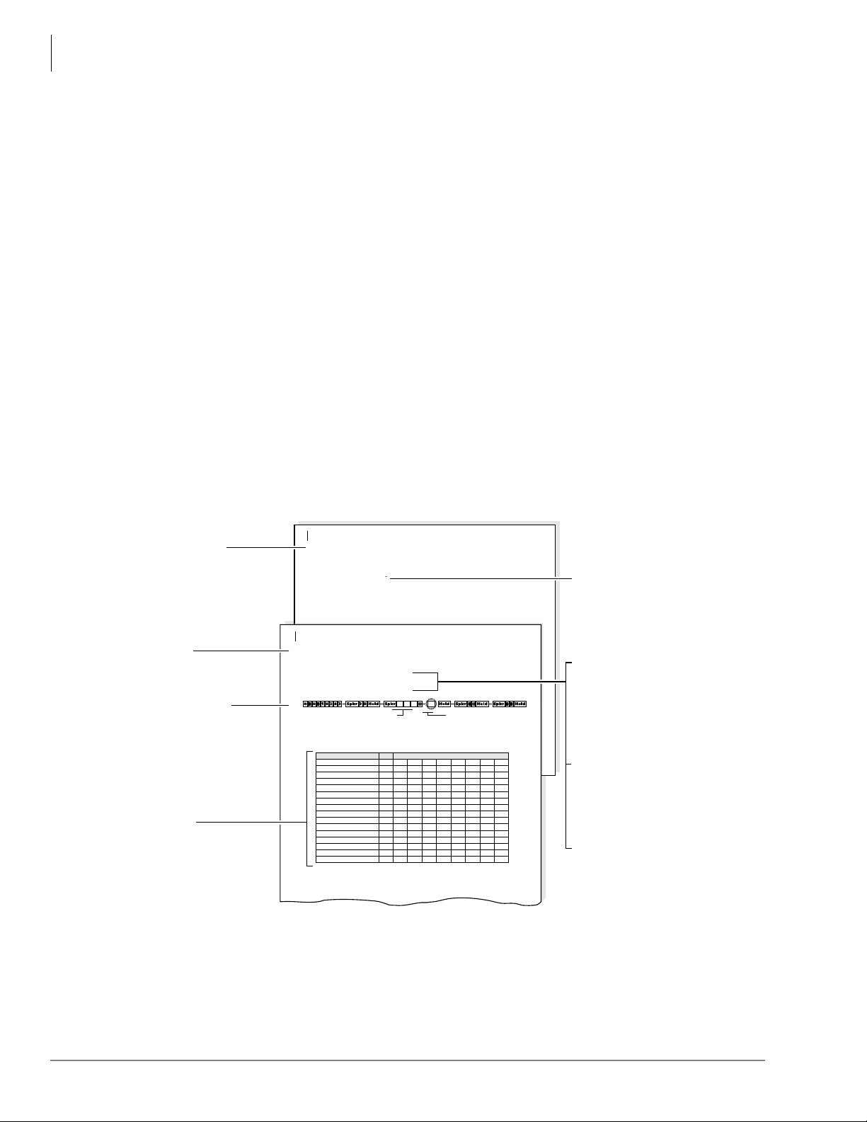
Programming Section Layout
Each programming section within a chapter begins with the program’s number and title, followed
by processor and program type, initialized default, program sequence, then record sheets. A
program overview and additional program information are given after the record sheets
(see Figure 1-1).
Note Some common program sections also include examples for your convenience.
Program Overview
Brief description of program
function(s).
Number/Title
Program Sequence
Keystrokes for entering data
from system record sheets
follow a pattern, consisting of a
five-step process described and
illustrated in “Program
Sequence” on Page 1-13.
Record Sheet
Provides a list of available
features. The sheet is used to
record the assignment of
features or the operation of each
program. Each sheet provides
space to record data. This data
will be referred to when
programming the system.
System Programs
Program 30 Station Class of Service
Program 30 Overview
Program 30 enables or disables features for individual telephones at the station level. The following
text describes Program 30 LEDs.
Privacy Override, LED 19
With Privacy Override enabled (LED 19 ON), a station can override calls and listen to a CO line
conversation by pressing a common CO line button (not a [DN] button). You can set a warning tone
for Privacy Override (see Program 10-2).
System Programs
Program 30 Station Class of Service
Program 30
Station Class of Service
Processor Type: DK14/DK40/DK424
Program Type: System
Initialized Default: LEDs 01, 05 and 07 for all ports
SELECT = Station Logical Port Number(s) Buttons/LEDs
Feature LED
20
19
18
17
16
15
14
13
12
11
10
09
08
07
06
05
Light LEDs for the port specified in the
last step. All LEDs marked with an “X”
in the table below should be lit.
Port
2174
Additional Program
Information
Additional details on the program
features that were given on the
system record sheet.
Processor Type
Gives the type of processor that is
compatible with the given program.
Be sure to read this information
before attempting to use a program
with your system application.
Program Type
Type of function the program
performs. Can be: Initialization,
Test System, Station, Toll
Restriction or Least Cost Routing.
Initialized Default
Default configuration set by
Program 91-9 “System
Initialization” when the system is
first installed or re-initialized.
Figure 1-1 System Record Sheet Sample
1-10 Strata DK Programming 5/00
Page 23

Program Sequence
Detailed data entry instructions are on the top of each record sheet (see Figure 1-2).
Overview
How to Program a Strata DK System
➤ To use the program sequence on the record sheet
1. From the programming telephone, enter the programming mode by pressing a series of shaded
buttons. The shaded buttons represent the entry sequence for all programs.
2. Enter the program number. This sequence is unique for every program. The buttons are white
on every record sheet.
3. Enter the program data. Again, this sequence is unique for every program. The buttons are
white on every record sheet. To make another entry, repeat this step until ready to exit the
current program.
4. Exit the current program. This sequence never changes, and the buttons are always shaded.
Upon exiting the current program, repeat Step 2 to enter another program, or continue with
Step 5 to exit the programming mode entirely.
5. Exit the programming mode by pressing the same button sequence as in Step 4. This sequence
also never changes and is always shaded.
Another Program
More Data
Overview
Step 1
Enter Program Mode
(Do not press or [DN] button)
Step 2
Enter Program Number
Step 3
Enter Program Data
Step 4
Exit Current Program
Step 5
Exit Program Mode
(LED Buttons)or
and/or
Figure 1-2 Programming Button Sequence Overview
1697
Strata DK Programming 5/00 1-11
Page 24

Overview
How to Program a Strata DK System
Programming Data Variations
There are two different ways to enter data in Step 3 (Figure 1-2) of a program: pressing the buttons
on the dial pad and pressing the LED buttons. Many programs are multidimensional and involve
both types of entry.
Simple Programs
Simple programs such as Program 00, only require data to be specified through the dial pad. Data
entered from the dial pad displays on the programming digital or electronic telephone’s LCD,
along with prompts and confirmations.
Multidimensional Programs
Once a program number is entered, the first dimension (usually a CO line number, a station port
number, or a range of ports) must be specified. Upon specifying this first dimension on the dial
pad, programming button LEDs 01~20 light in the default configuration.
The status of each LED can be changed by pressing its associated button. Pressing the button while
its LED is lit turns the LED Off; pressing the button while its LED is Off turns the LED On. An
example of multidimensional programming is Program 30.
Range Programming
Data can be entered for a range of stations, [DN] reference ports and CO lines with some
programs.
➤ To enter a range
➤ Enter a “
” between the starting point of a range and the ending point of a range.
For example, to program the station range of 001~010 for Program 35, press
♦ When programming a range of station ports, the station’s programming LEDs indicate
whether the data programmed matches for all items in the range:
♦ LED On: Indicates that all ports in the range are programmed with the data choice that
lights the particular LED.
♦ LED Off: Indicates that all ports in the range are programmed with the data choice that
does not light the particular LED.
♦ LED Flashing: Indicates that data is currently inconsistent for all ports in the range. Some
may be programmed with the LED On; some with the LED Off.
CO Line Programming
Since the programming telephone only has 20 buttons, data can only be entered for 20 CO lines at
a time.
➤ To program another range
➤ Press the 3DJH or 6FUROO button below the LCD.
.
For example, to change from one range to another in Program 15, enter the program code, then
press
6FUROO to advance or 3DJH to go back to another range.
If the programming telephone is a digital telephone, all CO lines within a range can be
activated or deactivated for a feature by pressing the
➤ Press 9RO▲ to turn all LEDs On; press 9RO ▼ button to turn all LEDs Off.
9RO▲/9RO ▼ buttons.
1-12 Strata DK Programming 5/00
Page 25
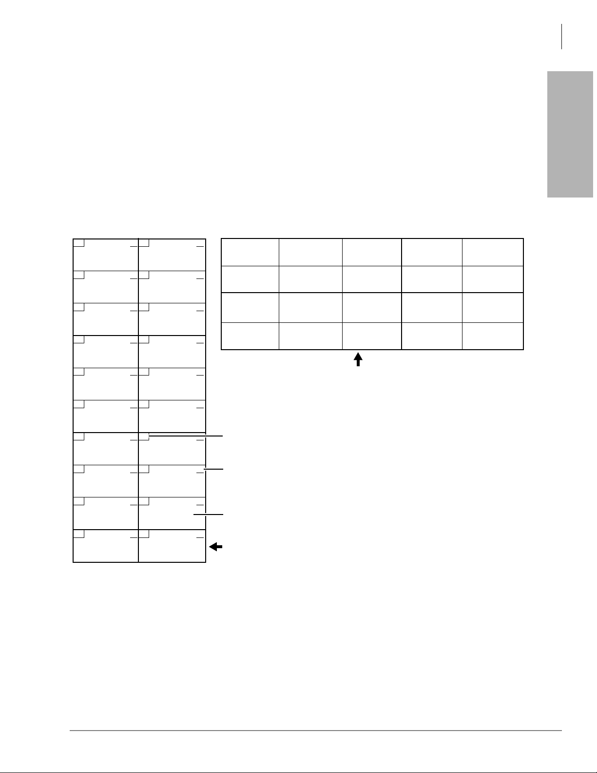
➤ To check the status of a CO line in Program 15
Overview
How to Program a Strata DK System
1. Press the
0RGH button (below the LCD) after entering the program code.
2. Then enter the CO line number to be verified.
3. Press
to display the status of the CO line and to advance to the next CO line.
Programming LED Buttons Keystrip Template
You place a special buttonstrip template (see Figure 1-3) over the 20 flexible feature buttons of the
programming telephone. The template assigns a series of numbers to each of the 20 buttons that
correspond with tables found on the record sheets for programming purposes.
Since each button represents more than one CO line, depending on the CO line range selected, the
template assigns more than one number to each button.
10 20
30, 50, 70
90, 110, 130,
150, 170, 190
09 19
29, 49, 69
89, 109, 129,
149, 169, 189
08 18
28, 48, 68
88, 108, 128,
148, 168, 188
07 17
27, 47, 67
87, 107, 127,
147, 167, 187
06 16
26, 46, 66
86, 106, 126,
146, 166, 186
05 15
25, 45, 65
85, 105, 125,
145, 165, 185
04 14
24, 44, 64
84, 104, 124,
144, 164, 184
03 13
23, 43, 63
83, 103, 123,
143, 163, 183
02 12
22, 42, 62
82, 102, 122,
142, 162, 182
01 11
21, 41, 61
81, 101, 121,
141, 161, 181
9
100, 120, 140,
8
7
6
5
4
3
2
153, 173, 193
1
152, 172, 192
0
40, 60, 80
160, 180, 200
39, 59, 79
99, 119, 139,
159, 179, 199
38, 58, 78
98, 118, 138,
158, 178, 198
37, 57, 77
97, 117, 137,
157, 177, 197
36, 56, 76
96, 116, 136,
156, 176, 196
35, 55, 75
95, 115, 135,
155, 175, 195
34, 54, 74
94, 114, 134,
154, 174, 194
33, 53, 73
93, 113, 133,
32, 52, 72
92, 112, 132,
31, 51, 71
91, 111, 131,
151, 171, 191
9
8
7
6
5
4
3
2
1
0
16, 36, 56, 76
96, 116, 136,
156, 176, 196
11, 31, 51, 71
91, 111, 131,
151, 171, 191
06, 26, 46, 66
86, 106, 126,
146, 166, 186
01, 21, 41, 61
81, 101, 121,
141, 161, 181
17, 37, 57, 77
97, 117, 137,
157, 177, 197
12, 32, 52, 72
92 112, 132,
152, 172, 192
07, 27, 47, 67
87, 107, 127,
147, 167, 187
02, 22, 42, 62
82, 102, 122,
142, 162, 182
1000-series digital telephone strip - shows programming button/LED
assignment locations. Shown as reference only - not available as an
individual strip.
LED Buttons and CO line numbers (01~20)
Last digit of EK port number for
programs with a format like
CO line numbers (21~200)
2000-series digital telephone strip - supplied with each
Programming Manual
system. Can also be used with 6000- and 6500-series electronic telephones.
18, 38, 58, 78
98, 118, 138,
158, 178, 198
13, 33, 53, 73
93, 113, 133,
153, 173, 193
08, 28, 48, 68
88, 108, 128,
148, 168, 188
03, 23, 43, 63
83, 103, 123,
143, 163, 183
71, *72, and *73
*
19, 39, 59, 79
99, 119, 139,
159, 179, 199
14, 34, 54, 74
94, 114, 134,
154, 174, 194
09, 29, 49, 69
89, 109, 129,
149, 169, 189
04, 24, 44, 64
84, 104, 124,
144, 164, 184
20, 40, 60, 80
100, 120, 140,
160, 180, 200
15, 35, 55, 75
95, 115, 135,
155, 175, 195
10, 30, 50, 70
90, 110, 130,
150, 170, 190
05, 25, 45, 65
85, 105, 125,
145, 165, 185
Strata DK
and each Documentation Package that ships with the
Overview
1843
Figure 1-3 LED Buttons Programming Keystrips
Strata DK Programming 5/00 1-13
Page 26

Overview
First-time Programming
First-time Programming
Follow these general procedures the first time you install a system or after major hardware changes
and/or you need to start from scratch.
Step 1: Check Minimum Hardware Requirements
A system must have the following minimum hardware installed for programming, as described in
the Installation chapters of the Strata DK Installation and Maintenance Manual.
➤ To check hardware requirements on the DK14 and DK40i
1. Make sure the base cabinet power supply was tested and is functional.
2. Make sure a 20-button digital LCD DKT telephone (equipped with a programming template)
is connected to any digital telephone circuit (Base KSU, PDKU, QCDU, KCDU or RDSU
digital port); or make sure that a 20-button electronic LCD EKT telephone is connected to a
PEKU electronic port (not PESU).
♦ DK14 and DK40i: make sure the Base KSU’s BATT jumper is in the On position.
➤ To check hardware requirements on the DK424 and DK424i
1. Make sure the base cabinet power supply was tested and is functional.
2. If using an RCTUE/F, remove the small jumper PCB (MBJU) from the front side of the
DK424 base unit backplane (between slot R11 and the RCTU slot. All other RCTUs require
the MBJU PCB. This does not apply to DK424i.
3. Make sure an that the BATT jumper is in the On position for all processors.
4. Make sure a PDKU or PEKU, is installed in the first slot of the in the base cabinet (S11 or
S101) if RSIU is not installed, or if RSIU is installed in S12 or S102).
5. Make sure a 20-button LCD DKT or EKT telephone (equipped with programming template) is
connected to physical port 005 and/or port 013 (PDKU or PEKU - circuit 6/slot 11or 101 and/
or circuit 6/slot 12 or 102). Do not use RDSU or PESU in the programming telephone slot.
Step 2: Initialize the System
1. From a 20-button LCD programming telephone, or from DKi Admin on a PC, run Program
91–9 twice in succession to initialize the system. At this point it is not necessary that all PCBs
are installed. However, if they are, Program 03 codes are automatically assigned to the
appropriate slots.
CAUTION! If you run Program 91-9 while the system is in service, all program data is
erased and all calls are dropped.
Program 91-9 sets the following elements to initial default status:
♦ Data for Programs 00~*99
♦ Speed Dial Memory
♦ Logical/Physical Port Locations
♦ Voice Mail Identification Codes
♦ Character Message Memory
1-14 Strata DK Programming 5/00
Page 27

♦ Timed Reminders
♦ Digital Telephone Volume Levels
♦ Call Forward Memory (Power Off, then On).
♦ Station Message Waiting Status
♦ Caller ID Lost Call Memory
2. Install all PCBs. Run Program 91-1 to inform the software of the system hardware
configuration.
Step 3: Run Programs 03 and 19-1
1. Run Program 03 for all PCBs that have options.
2. Run Program 19-1 to inform the software of the system option Alternate BGM slot.
Step 4: Run Program 00
➤ Run Program 00 - Part 1 to assign remote maintenance security codes. Run Program 00 - Part
2 to test the processor and RAM.
Overview
First-time Programming
Overview
Step 5: Set Date, Time and Day
You can set date, time and day anytime - individually or all.
1. Use DKT or EKT assigned to logical Port 000 or attendant console.
2. Make sure the handset is on-hook.
3. Set the date:
[PDN]
4. Set the time:
[PDN]
5. Set the day:
[PDN]
5HGLDO
Date in year/month/day format
(YYMMDD). If month or day is
single digit, precede with a zero.
5HGLDO
Time in hours/minutes/seconds format (HHMMSS
from 000000 to 235959). If any of these values is
single digit, precede with a zero.
5HGLDO
Enter the digit for today’s day:
= Sunday
= Monday
= Tuesday
= Wednesday
=Thursday
=Friday
= Saturday
Step 6: Run Additional Programs as Required
Strata DK Programming 5/00 1-15
Page 28
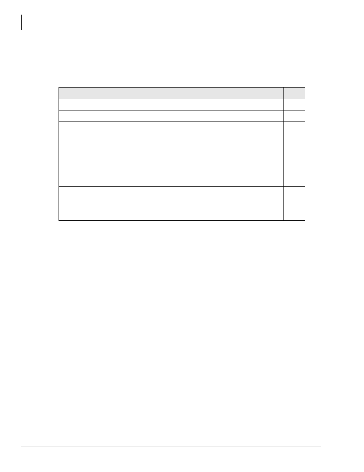
Overview
Programming Examples
Programming Examples
Some commonly used programs have explicit examples (listed below). Refer to these pages to
help familiarize you with running these programs.
Program 91-9 — System Initialization 2-3
Program 90 — Initializing Programs 00~*99 2-5
Program 91-1— Automatic PCB Recognition and Logical/Physical Port Initialization 2-2
Program Page
Program 92 — Initializing Speed Dial Numbers, VM ID Codes, Character Message Memory,
Timed Reminders, Digital Telephone Volume, and Call Forward Backup Memory
Program 00 — Software Check 2-12
Program 03 — DK14 Slot Assignments and DK40i/DK424 Flexible PCB Slot Assignments
Program 04 — Station Logical Port Primary Directory Intercom or Number Assignment 3-17
Program 30 — Station Class of Service 3-80
Program 33 — Station Hunting 3-93
2-9
3-3,
3-4,
3-6
1-16 Strata DK Programming 5/00
Page 29

Initialization & Test 2
This chapter gives you information on the Strata DK’s Initialization and Test programs. The
programs in this chapter are not given in numerical order, rather in order of importance. These
programs include:
♦ Program 91-9 – System Initialization
♦ Program 90 – Initialize Programs 00~99
♦ Program 91-1 – Automatic PCB Recognition and Port Renumber
♦ Program 91-2 – Data Transfer from Temporary Memory to Working Memory
♦ Program 92 – Initializing Misc. Backup RAM
♦ Program 00 – Part 1: Software Check
♦ Program 00 – Part 2: RCTU RAM Test
Examples are also given for these programs - except Programs 91-2 and Program 00 - Part 2.
Initialization & Test
Strata DK Programming 5/00 2-1
Page 30
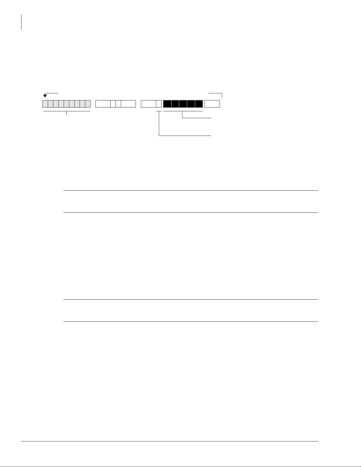
Initialization & Test
Program 91-9 – System Initialization
Program 91-9 – System Initialization
Processor Type: DK14, DK40i, all RCTUs and BCUs
Program Type: Initialization
Initialized Default: See individual programs
Repeat a second time after LEDs 01, 03, 05, 07, and 09 extinguish.
✱ ✱ ✱ ✱ 6SNU +ROG 6SNU +ROG Program Telephone Exits Program Mode
Enter programming mode.
(Do not press [DN] button.)
Program 91-9 Overview
Note Always run Program 91-9 before entering the customer database when first installing a
system or when its software must be set to the default configuration, but not while system
is in service.
CAUTION! If you run Program 91-9 while the system is in service, it will erase all program
data and drop all calls.
Running Program 91-9 also runs Program 03 and assigns codes to all PCBs (except options)
installed. It also erases all Program 03 option codes for piggyback PCBs, DSS consoles, RRCS,
etc., except the RCOS PCB Code (17).
Program 91-9 erases all random or programmed data in all Strata DK software programs and sets
all program data to the default value. It automatically runs all other initialization Programs 9000~99, 91-1, and 92-1~9. It also brings back logical and physical ports to their initialized
settings.
If you are installing the system processor(s) for the first time, after initializing the system, test the
RAM: run Program 00 Part 2.
Press Buttons 01, 03, 05, 07, and 09.
LEDs 01, 03, 05, 07, and 09 must be On.
LCD Displays: SYSTEM INITIALIZATION
CAUTION! Running Program 00 Part 2 drops all calls in progress and interrupts telephone
service for 15 seconds. This test will not erase programmed customer data.
Important! Do not use Program 91-9 if you are only making minor programming changes and
system programming is basically correct.
Note Run Program 03 after Program 91-9 for: PCBs with options such as Dual-tone
Multi-frequency Receivers K5RCU, QRCU3, RRCS, BRCS, and DSS consoles, etc.
...or if entering a customer database into system RAM memory before other system PCBs
(stations, lines, options) are installed. Program 03 identifies which universal and option
PCBs (e.g., RRCS, BRCS, etc.) are to be installed in each cabinet slot.
2-2 Strata DK Programming 5/00
Page 31

Program 91-9 Example
Action (press buttons + LED Buttons) LCD Response
1. Use the programming LCD electronic or digital telephone. (See
“Programming Examples” on Page 1-16.)
Initialization & Test
Program 91-9 – System Initialization
No. N-N
Jan 20 Sun 06:43
1
2. ✱✱✱✱
Enter programming mode. (Do not press [DN] button.)
3. 6SNU6SHDNHU+ROG
Access Program 91. System beeps after 6SNU6SHDNHU is pressed
to indicate program number may be entered.
4. 6SNU6SHDNHU
Prepare the system for a station port selection.
5. Press System Initialization
6. Press LED Buttons 01, 03, 05, 07, and 09 (LEDs turn On) System Initialization
7. Press +ROG
The telephone will exit the programming mode and button LEDs 01,
03, 05, 07, and 09 will go out after a short delay. Make sure all LEDs
go out before proceeding to Step 8.
8. Repeat Steps 1~7 a second time.
1. N-N is the Program Telephone [DN].
Program Mode
Program = 91
91 Select =
(Month Day Time)
(Month Day Time)
Data Store
Initialization & Test
No. N-N
No. N-N
Strata DK Programming 5/00 2-3
Page 32

Initialization & Test
Program 90 – Initialize Programs 00~*99
Program 90 – Initialize Programs 00~*99
Processor Type: DK14, DK40i, all RCTUs and BCUs
Program Type: Initialization
Initialized Default: See individual programs
✱ ✱ ✱ ✱ 6SNU +ROG 6SNU +ROG 6SNU +ROG 6SNU +ROG
Enter programming
mode
Programs to be initialized. Add
a range of program numbers
by entering XX*XX or XX**XX.
Press LED Buttons 01 and 02
LEDs 01 and 02 must be On
Program 90 Overview
Program 90 enables you to clear all customer data and initialize individual programs or range of
programs.
Important! When installing the system, you must run Program 91-9 which runs Program 90
(before running any other program); if you do not, the system could begin to operate
erratically.
Notes
● Running Program 91-9, automatically runs Program 90.
● To initialize all programs without dropping calls or erasing user names, speed dial numbers,
voice mail ID codes, etc., enter
● Each “*” program record sheet immediately follows the program record sheet having the same
number (example: *31 follows 31 record sheet). However, in system memory all “*” programs
follow Program 99. Therefore, “*” program ranges must be initialized separately from nonstar programs unless initializing all system Programs (00**99).
Exit programming modeEnd Program 90
LEDs 01 and 02 must flash
as “Programs to be initialized.”
For example, to initialize Programs 30, *30, 31, *31, and 32: initialize the range (30*32), for
Programs 30, 31, 32; and the range (*30**31), for Programs *30 and *31.
● If you are installing the system for the first time, run Program 91-9 to erase random data from
RAM (caused by battery jumper movement to the internal battery). You can then skip Program
90, since Program 91-9 automatically runs Program 90.
2-4 Strata DK Programming 5/00
Page 33

Program 90 Example
Action LCD Response
1. Use the LCD programming phone per Minimum Hardware
Requirements on Page 1-14.
Initialization & Test
Program 90 – Initialize Programs 00~*99
No. N-N
Jan 20 Sun 06:43
1
2. Enter Program mode by pressing ✱✱✱✱.(Do not press [DN]
button.)
3. 6SNU6SHDNHU+ROG
Access Program 90. System beeps after 6SNU6SHDNHU is pressed
to indicate program number may be entered.
4. 6SNU6SHDNHU
Prepare the system for the programs to be initialized.
5. ✱✱+ LED buttons 01 & 02
Enter Program numbers individually, followed by #, or in a range. For a
range, separate the low program number and the high program
number with an asterisk.
✱✱ initializes all Programs 00~
Star ✱ Program memory follows Program 97.
6. +ROG
Secure data in system programming. LEDs 01 and 02 flash.
7. 6SNU6SHDNHU
Prepare system for another selection (go back to Step 5) or exit
Program 90 (continue with Step 8).
8. +ROG
Secure default data in system memory. LED 01 and 02 continue to
flash.
9. 6SNU6SHDNHU
Exit Program 90. Enter another program number (see “Program 92
Example” on Page 2-10) or exit programming mode (go to Step 10).
System beeps to indicate it is exiting Program 90.
99.
Program Mode
Program = 90
90 Select =
90 Select = 00**99
Data Clr
90 Select = 00**99
Data Programmed
90 Select =
90 Select = ##
Data Programmed
Program =
Data Store
Initialization & Test
10. +ROG
Exit programming mode.
The system will not allow the 6SNU6SHDNHU LED to light to reenter the programming mode.
1. N-N is the Program Telephone [DN].
Strata DK Programming 5/00 2-5
Jan 20 Sun 06:43
No. N-N
Page 34

Initialization & Test
Program 91-1 – Automatic PCB Recognition and Port Renumber
Program 91-1 – Automatic PCB Recognition and Port
Renumber
Processor Type: DK14, DK40i, all RCTUs and BCUs
Program Type: Initialization
Initialized Default: None
✱ ✱ ✱ ✱ 6SNU +ROG 6SNU +ROG Program Telephone Exits Program Mode
Enter programming mode.
(Do not press [DN] button.)
Program 91-1 Overview
Program 91-1 makes slot code assignments to installed PCBs that do not have options - such as a
PDKU without a Data Interface Unit or Off-hook Call Announce (OCA), the common control
without a Dual-tone Multi-frequency Receiver (RRCS), K5RCU, QRCU3, etc.
Program 91-1 also sets physical and logical ports to their initialized settings - even if you
previously relocated them. (See Program 01 and 02 for initialized settings.). Programs 04, 04, 05,
05, 09, or 71 are not affected.
CAUTION! Running Program 91-1 drops all calls.
Important! To identify Program 03 PCB slot codes, run Program 91-1 after you install all
PCBs.
Notes
● You can run Program 91-1 after setting PCB option codes with Program 03; this does not erase
option codes. For example, if Slot 00 is assigned code 92, Program 91-1 will not erase the
codes previously assigned with Program 03.
Press LED Buttons 01 and 02.
LEDs 01 and 02 must be On.
LCD Displays:
Renumber and Reset
91 SELECT = 1
● If you install PCBs before initializing the system with Program 91-9, it is not necessary to run
Program 91-1 to assign the Program 03 PCB slot codes for the installed PCBs. You must
always run Program 03 to identify PCB options such as K5RCU, QRCU3, and RRCS codes
92, 93 and 94 and PDKU codes 61, 62, and 64, etc.
2-6 Strata DK Programming 5/00
Page 35

Program 91-1 Example
Action (press buttons + LED Buttons) LCD Response
1. Use the LCD programming phone per Minimum Hardware
Requirements on Page 1-14.
Initialization & Test
Program 91-1 – Automatic PCB Recognition and Port Renumber
No. N-N
Jan 20 Sun 06:43
1
2. ✱✱✱✱
Enter programming mode. (Do not press [DN] button.)
3. 6SNU6SHDNHU+ROG
Access Program 91. System beeps after 6SNU6SHDNHU is pressed
to indicate program number may be entered.
4. 6SNU6SHDNHU
Prepare the system for a station port selection.
5. Press
6. Press LED Buttons 01 and 02 (LEDs turn On)
7. Press +ROG
The telephone will exit the programming mode and button LEDs 01
and 02 will go out after a short delay.
1. N-N is the Program Telephone [DN].
Program Mode
Program = 91
91 Select =
91 Select = 1
Renumber and Reset
91 Select = 1
Renumber and Reset
(Month Day Time)
Data Store
Initialization & Test
No. N-N
Strata DK Programming 5/00 2-7
Page 36

Initialization & Test
Program 91-2 – Data Transfer from Temporary Memory to Working Memory
Program 91-2 – Data Transfer from Temporary Memory
to Working Memory
Processor Type: DK14, DK40i, all RCTUs and BCUs
Program Type: Initialization
Initialized Default: See individual programs
✱ ✱ ✱ ✱ 6SNU +ROG 6SNU +ROG Program Telephone Exits Program Mode and Transfers Data
Enter programming mode.
(Do not press [DN] button.)
Program 91-2 Overview
Program 91-2 simulates turning system power Off for five seconds then On to transfer data from
temporary memory to working memory.
This power Off / power On sequence is required when programming with a telephone or when
using DKi Admin/DKi Backup. In these cases Program 03, 41-2, 50 and 76-1 data must be
transferred from temporary to working memory.
Program 91-2 does not change or erase any programmed data including directory numbers set in
Program 04 and *04 or logical/physical port assignments in Program 01 and 02.
CAUTION! Running Program 91-2 drops all calls and renders the system inoperative for
up to eight seconds.
Press LED Buttons 03 and 04.
LEDs 03 and 04 must be On.
LCD Displays:91 SELECT = 2
Programming
Taking Effect
2-8 Strata DK Programming 5/00
Page 37

Program 92 – Initializing Misc. Backup RAM
Program 92 – Initializing Misc. Backup RAM
Processor Type: DK14, DK40i, all RCTUs and BCUs
Program Type: Initialization - Includes: Initializing Speed Dial Number, VM ID Codes, Character
Message Memory, Timed Reminders, Digital Telephone Volume, Called ID, ANI, and
Call Forward Backup RAM
Initialized Default: See individual programs
Clear more data
✱ ✱ ✱ ✱ 6SNU +ROG 6SNU +ROG 6SNU +ROG 6SNU +ROG
Initialization & Test
Enter programming
mode.
SELECT = Press appropriate
buttons as shown below.
Clears Station Speed Dial, Voice Mail ID Codes, and LCD memos
Clears System Speed Dial and LCD memos assigned to System Speed
Clears Character Message Memory (Station and System) and User
Clears Timed Reminders.
Resets digital telephone volume levels to initialized settings, specifically,
+ROG Power Off 5
assigned to Station Speed Dial numbers.
Dial numbers.
Name/Number Display.
speaker volume levels for Internal Calls [DN], Tone/BGM, Busy Override
(muted ring), and Ring volume to approximately mid-range on all DKTs.
Program 92-5 does not affect digital telephone handset receiver volume
levels. Use Program 27 to set off-hook digital telephone handset
receiver volume levels.
Clears Call Forward and Message Waiting Memory
seconds; then
Power On
(all stations). Program 92-9 does not affect Call
Forward External or Fixed Call Forward settings.
End Program 92.
Exit programming
mode.
Initialization & Test
Program 92 Overview
Program 92 clears all previously entered or random data (of the type listed) but does not clear data
in system Programs 00~99.
CAUTION! You must run Program 92 when first installing the system or an RCTU; if you
do not, the system could begin to operate erratically.
Running Program 91-9 automatically runs Program 92 (1~9) to erase customer
data.
Notes
● Running Program 92-5 does not affect digital telephone handset receiver volume levels. Use
Program 27 to set off-hook handset receiver volume levels for digital telephones.
Strata DK Programming 5/00 2-9
Page 38

Initialization & Test
Program 92 – Initializing Misc. Backup RAM
● Program 92-9 does not affect Call Forward External or Fixed Call Forward settings.
● You must power the system Off then back On to clear telephone LCD Call Forward Displays
and Call Forward button LEDs. Call Forward memory is cleared when you run Program 92-9,
even if system power is not cycled.
Program 92 Example
Action (press buttons + LED Buttons) LCD Response
1. Use the programming LCD electronic or digital telephone. (See “Step
1: Check Minimum Hardware Requirements” on Page 1-14.)
No. N-N
Jan 20 Sun 06:43
1
2. ✱✱✱✱
Enter programming mode. (Do not press [DN] button.) System beeps
after 6SNU6SHDNHU is pressed to indicate program number may
be entered.
3. 6SNU6SHDNHU+ROG
Access Program 92.
4. 6SNU6SHDNHU
Prepare the system for selection of programs to initialize. For new
system installation perform all 1~4.
5.
Select one of the following.
+ LED Buttons 01 & 03
Clears Station Speed Dial, Voice Mail ID codes, and LCD memos
assigned to station speed dial numbers.
or...
+ LED Buttons 01 & 04
Clears System Speed Dial and LCD memos assigned to system
speed dial numbers.
or...
+ LED Buttons 02 & 03
Clears Character Message Memory (station and system) and user
name display.
or...
+ LED Buttons 02 & 04
Clears timed reminders.
Program Mode
Program = 92
Data Store
92 Select =
92 Select = 1
Each Dial Clr
92 Select = 2
Common Dial Clr
92 Select = 3
Msg Clr
92 Select = 4
Tmr Reminder Clr
or...
+ LED Buttons 01 & 05
Presets the Ring, Speaker, Mute Ring, and Intercom Tone, BGM,
volume levels of all digital telephones to approximately mid-range.
or...
+ LED Buttons 03 & 04
Clears Call Forward and Message Waiting (R3) Memory except Fixed
Call Forward Memory.
6. +ROG
LEDs lit in Step 5 turn off to secure data in system programming.
Repeat Steps 4~6 until Step is completed.
1. N-N is the Program Telephone [DN].
92 Select = 5
DKT VR Initial
92 Select = 9
Back Up RAM Clr
92 Select = (1~0)
Data Programmed
2-10 Strata DK Programming 5/00
Page 39

Initialization & Test
Program 92 – Initializing Misc. Backup RAM
Action (press buttons + LED Buttons) LCD Response
7. 6SNU6SHDNHU
Prepare system for another selection (go back to Step 5) or exit
Program 92 (continue with Step 8).
8. +ROG
Initialized data in system memory (LEDs got out).
9. 6SNU6SHDNHU
Exit Program 92. Enter another program number (see “Program 30 –
Station Class of Service” on Page 3-76) or exit programming mode (go
to Step 10). System beeps to indicate it is exiting Program 92.
10. +ROG
Exit programming mode.
92 Select =
92 Select = ##
Data Programmed
Program =
No. N-N
Jan 20 Sun 06:43
Initialization & Test
Strata DK Programming 5/00 2-11
Page 40

Initialization & Test
Program 00 – Part 1: Software Check
Program 00 – Part 1: Software Check
Processor Type: DK14, DK40i, all RCTUs and BCUs
Program Type: Test - Includes: Remote Maintenance Security Code Assignments
Initialized Default: None
✱ ✱ ✱ ✱ 6SNU +ROG 6SNU +ROG 6SNU +ROG 6SNU +ROG
Select = Code Password Codes (4 digits)
Select =
Code
0 ROM Version (not programmable)
1
2
8
9
1st Level Password
2nd Level Password
Software RAM Checksum (not programmable)
Power Cycle Counter (not programmable)
Item
VER=
DKT LCD Display
(see table below)
DKT LCD Display Processor Type DKT LCD Display Processor Type
QMA DK8 RAA4X RCTUA4
PSSA DK16 RBA4X RCTUBA4/BB4
WMA4
TMA4
RAA RCTUA R1/R2
RBA RCTUB R1/R2
RCA RCTUC R1/R2
RAA3X
RBA3X
RCA3X
REA3X RCTUE4/F4
DK16e, DK40, DK40i REA4X RCTUE4/F4
RCTUBA3/RCTUBB3
RCTUC3/D3
Password or S/W
Check Codes
LCD Display
Ver =
(See tables below)
Password =
Password =
Sum =
Counter =
- KEY X
X = 1, 2, or 3
ROM Version
DK14 RCA4X RCTUC4/D4
B1A4X
B2A4X
B3A4X
RCTUA3
B5A4X
(If RKYS, KKYS,
or QKYS is installed)
B1CU
B2CAU/BU
B3CAU/BU
B5CAU/BU
4994
Key Type Description
KEY 1 RKYS1, KKYS1, or QKYS installed. Built-in Auto Attendant software.
KEY 2 AA and ACD software. RKYS2, KKYS2 installed.
KEY 3 RKYS3, KKYS3 installed. ACD/MIS and AA installed.
2-12 Strata DK Programming 5/00
Page 41

Program 00 Part 1 - Overview
This program enables you to run various checks on the Strata DK System.
DK14: the QKYS feature key must be installed on the QRCU3 PCB to allow AA.
DK40i: the KKYS feature key must be installed on the K5RCU PCB to allow AA.
DK424 and DK424i: the RKYS feature key must be installed on the RCTU or BCU to allow AA,
ACD, and ACD/MIS.
Code 0, ROM Version
Code 0 displays the software version of the system processor PCB or on the DK40i Base KSU, or
DK14 KSU, and if installed, the RKYS, KKYS, or QKYS key type. See the Program 00 Record
Sheet for an illustration of software displays. This information cannot be altered with this program.
Code 1, Level 1 Security Code
Use to assign a Remote Maintenance security code that allows entry to all programs and data.
Code 2, Level 2 Security Code
Use this program to assign a Remote Maintenance security code that allows entry to Programs
30~39, 77~89, and 30~31.
Initialization & Test
Program 00 – Part 1: Software Check
Initialization & Test
Important! When using a DKi Admin PC, either Security Code (1 or 2) enables the DKi Admin
user full access to all Strata DK programs. Always change Security Code 1 and
Code 2 to prevent unauthorized programming changes by DKi Admin users that
may try to log-in remotely with the default security code: 0000.
Code 8, Software RAM Checksum and Code 9, Power Off Counter
For factory purposes only.
Program 00 Part 1 - Example
Action (press buttons + LED Buttons) LCD Response
1. Use the programming LCD electronic or digital telephone. (See “First-
time Programming” on Page 1-14.)
2. ✱✱✱✱
Enter programming mode. (Do not press [DN] button.)
3. 6SNU6SHDNHU+ROG
Speaker beeps to indicate when to enter program number. Access
Program 00.
4. 6SNU6SHDNHU
Prepare system for a selection.
5. Select one of the following attributes:
Jan 20 Sun 06:43
Program Mode
Program = 00
00 Select =
No. N-N
Data Store
1
00 Select = 0
View the software version. This attribute can not be edited.
or...
Strata DK Programming 5/00 2-13
RNAXNN-Key X
Note NN = The actual version
number and letter. See Program
00 record sheet for details).
X = 1, 2, or 3.
Page 42

Initialization & Test
Program 00 – Part 1: Software Check
Action (press buttons + LED Buttons) LCD Response
1111
Define the Level 1 remote maintenance security code from the System
Record Sheet (four digits maximum). Level 1 allows remote access to
all programs and data. Default Level 1 security code is “0000.”
or...
1111
Define the Level 2 remote maintenance security code from the System
Record Sheet (four digits maximum). Level 2 allows remote access to
programs 30~39 and 77~89 only. Default Level 2 security code is
“0000.”
or...
View the software RAM Checksum. This attribute can not be edited.
The default checksum may change.
or...
View the RPSU Power Cycle Counter. This attribute can not be edited.
The counter indicates the number of times power is removed from the
system after Program 00 was initialized via Program 90 or 91-9.
6. +ROG
Secure data in system programming. (Only works for “1” and “2”)
00 Select = 1
Password = 0000
00 Select = 2
Password = 0000
00 Select = 8
Sum = XXXXXXXXX
00 Select = 9
Counter = XXXX
00 Select = (0,1,2,8, or 9)
Data Programmed
7. 6SNU6SHDNHU
Prepare system for another selection (go back to Step 5) or exit
Program 00 (continue with Step 8).
8. +ROG
Secure Program 00 data in system memory.
9. 6SNU6SHDNHU
Exit Program 00. Enter another program number (see “Program 91-1
Example” on Page 2-7) or exit programming mode (go to Step 10).
System beeps to indicate it is exiting Program 00.
10. +ROG
Exit programming mode.
1. N-N is the Program Telephone [DN].
00 Select =
00 Select = ##
Data Programmed
Program =
No. N-N
Jan 20 Sun 06:58
2-14 Strata DK Programming 5/00
Page 43

Program 00 – Part 2: Processor RAM Test
Program 00 – Part 2: Processor RAM Test
Processor Type: DK14, DK40i, all RCTUs and BCUs
Program Type: Test - Includes: Remote Maintenance Security Code Assignments
Initialized Default: None
General RAM Test
Note See “Program 00 Part 2 - Overview” on Page 2-16.
✱ ✱ ✱ ✱ 6SNU +ROG 6SNU +ROG Tests RAM (15 seconds downtime)
Initialization & Test
Programming Telephone LCD Displays:
GENERAL RAM TEST
Display General RAM Test Results
✱ ✱ ✱ ✱ 6SNU +ROG 6SNU Programming Telephone LCD Displays:
DK424 DK14/DK40i
TEST 1 X=OK Y=OK TEST 1 =OK
or... or...
TEST 1 X=NG Y=NG
TEST 1 =NG
X=00000 X=00000
Where:
X = RCTUA, RCTUBA, RCTUC, B1CU, B2CAU, B3CAU, B5CAU
Y = RCTUD3, RCTUF, B2CBU, B3CBU, B5CBU
OK = RAM is good
NG = RAM is defective
An
X=NG or Y=NG RAM test result indicates a defective processor PCB;
change the appropriate (X or Y) processor PCB and retest RAM on the
newly installed processor PCB.
Replace the DK14 KSU or DK40i Base KSU if
Test 1=NG.
Backup RAM Test
Initialization & Test
✱ ✱ ✱ ✱ 6SNU +ROG 6SNU +ROGRCTU Tests RAM (15 seconds downtime)
Programming Telephone LCD Displays:
BACKUP RAM TEST
Strata DK Programming 5/00 2-15
Page 44

Initialization & Test
Program 00 – Part 2: Processor RAM Test
Display Backup RAM Test Results
✱ ✱ ✱ ✱ 6SNU +ROG 6SNU Programming Telephone LCD Displays:
DK424 DK14/DK40i
TEST 2 X=OK Y=OK TEST 1 =OK
or... or...
TEST 2 X=NG Y=NG
X=00000 X=00000
Where:
X = RCTUA, RCTUBA, RCTUC, B1CU, B2CAU, B3CAU, B5CAU
Y = RCTUD3, RCTUF, B2CBU, B3BU, B5CBU
OK = RAM is good
NG = RAM is defective
An
X=NG or Y=NG RAM test result indicates a defective RCTU PCB; change
the appropriate (X or Y) processor PCB and retest RAM on the newly
installed processor PCB.
Replace the DK14 or DK40i Base KSU if
Program 00 Part 2 - Overview
Use this program to test the RAM on system processor. If a RAM test error occurs during this test,
the processor causing the error should be replaced. In the case of two-PCB processors, isolation of
a RAM failure is indicated on the programming telephone X or Y (see above).
If the DK14 or DK40i processor fails the RAM test, the Base KSU must be replaced.
CAUTION! Running each RAM test drops all calls and interrupts telephone service for 15
seconds.
Note Running Program 00 RAM tests do not change or erase any customer data.
TEST 2 =NG
Test 1=NG.
2-16 Strata DK Programming 5/00
Page 45

System & Station 3
This chapter gives you programming information for the Strata DK system and its stations.
Program 01 – Station Logical Port Display and/or Change
Processor Type: DK14, DK40i, all RCTUs and BCUs
Program Type: Station
Initialized Default: Logical port number = physical port number
Program 90, 91-1, or 91-9 initializes Program 01
To Save existing Logical Port
✱ ✱ ✱ ✱ 6SNU +ROG 6SNU +ROG 6SNU +ROG 6SNU +ROG
SELECT = Physical Port Number
The logical port number associated with
the physical port displays after the
physical port number is entered.
Processor [PDN] Port Range Processor [PDN] Port Range
DK14 000~009 B1CU 000~055
DK40i 000~027 B2CAU/BU 000~111
RCTUA 000~031 B3CAU/BU 000~191
RCTUBA/BB 000~079 B5CAU/BU 000~335
RCTUC/D 000~239
RCTUE/F 000~335
6SNU
Enter new Logical Port
to change existing Logical Port
Program 01 Overview
Program 01 enables you to enter a physical port to display the associated logical port. You then
have the option to assign a new logical port to the physical port. (To return ports to their initialized
settings, see Programs 90 and 91.)
Note Record port locations on Program 04 record sheet.
System & Station
Strata DK Programming 5/00 3-1
Page 46

System & Station
Program 02 – Station Physical Port Display and/or Change
Program 02 – Station Physical Port Display and/or
Change
Processor Type: DK14, DK40i, all RCTUs and BCUs
Program Type: Station
Initialized Default: Logical port number = physical port number
Program 90, 91-1, or 91-9 initializes Program 02
To Save existing Physical Port
✱ ✱ ✱ ✱ 6SNU +ROG 6SNU +ROG 6SNU +ROG 6SNU +ROG
SELECT = Logical Port Number
The physical port number associated
with the logical telephone port displays
after the logical port number is entered.
Processor [PDN] Port Range Processor [PDN] Port Range
DK14 000~009 B1CU 000~055
DK40i 000~027 B2CAU/BU 000~111
RCTUA 000~031 B3CAU/BU 000~191
RCTUBA/BB 000~079 B5CAU/BU 000~335
RCTUC/D 000~239
RCTUE/F 000~335
6SNU
Enter new Physical Port
to change existing Physical Port
Program 02 Overview
Program 02 enables you to enter a logical port to display the associated physical port. You then
have the option to assign a new physical port to the logical port. (To return ports to their initialized
settings, see Programs 90 and 91.)
Notes
● Record port locations on Program 04 record sheet.
● The system allows only like ports to be reassigned (see below).
Allowed Not Allowed
Digital-to-Digital Ports (KCDU-QCDU-PDKUPDKU-RDSU Ports)
Electronic-to-Electronic Ports (PEKU-PEKUPESU Ports)
Attendant Console (DK424, DK424i only),
DSS, BGM or Amplified Conference Ports
should not be reassigned
Door Phone Ports (004, 012, 020, 028) should
not be reassigned
Tie/DID Line Ports – should not be reassigned
Standard Tel to Standard Tel Ports (QSTUKSTU-PSTU-RSTU-PESU-RDSU/RSTS)
PDKU to PEKU – cannot be exchanged
PSTU to PDKU – cannot be exchanged
PEKU to PSTU – cannot be exchanged
● RCIU/RCIS circuit assignments to CO lines are not affected by Program 01 and 02.
3-2 Strata DK Programming 5/00
Page 47

Program 03 for DK14 – Slot Assignments
Program 03 for DK14 – Slot Assignments
When DK14 is powered On, Program 03 automatically assigns the correct codes for installed
PCBs. No record sheet is needed. Refer to the following table for PCB slot and slot code
information:
DK14 Base KSU
System & Station
WMAU DKU
Slot Number 00 11 12 13 14
PCB Code 91 or 92 62 11 00 or 31 00
PCB Type QRCU3
Options OCA/DIU
Station Numbers 000~007 008~009
CO Line
Numbers
COU
and QCDU2
001~004
QSTU2 None
Notes
● In the DK14 software: QCDU2 digital ports are considered to be installed in slot 11. QCDU2
CO lines are considered to be installed in slot 12.
● opt=QRCU3
● opt=Always assigns 8 ports (000~007), digital ports (OCA/DIU). No DSS allowed.
● Always assigns 4 CO lines
● Always assigns 2 ports (008, 009) standard telephone ports
System & Station
Strata DK Programming 5/00 3-3
Page 48

System & Station
Program 03 for DK40i – Flexible PCB Slot Assignments
Program 03 for DK40i – Flexible PCB Slot Assignments
Processor Type: DK40i
Program Type: System
Initialized Default: PCB codes of PCBs installed prior to running Program 91-1 or Program 91-9
✱ ✱ ✱ ✱ 6SNU +ROG 6SNU +ROG Turn System Power Off (5 sec) then On
SELECT = Slot Number (00, 11~18)
CARD = PCB Code (See Reference Table)
Code 00 for empty slots (15~18), Base KSU has codes for PCBs
more codes
...or
Run Program 91-2
DK40i Base KSU
TBSU,
TCOU,
TDDU or
TBUU
or 77
KSTU2 TCIU2
00 or 3100 or
81
Slot Number
PCB Code
PCB Type
Options
Station/BRI
Port Numbers
CO/DID/BRI
Line Numbers
TMAU2 DKU
00 11 12 13 14
91, 92 or 9862 or 6400, 11, 16,
DK40i Expansion KSU
Cabinet Label
Slot Number
PCB Code
PCB Type
Options
Station/BRI Port Numbers
CO/Tie/DID/BRI/T1
Line Numbers
Notes
● For systems containing ISDN PCBs, immediately after running
Program 03, make sure to run Program *60 to identify all
station (NT/LT) and CO (TE) BRI circuits for each BRI circuit
installed. Program *60 causes station port and CO line shifting
on PCBs installed in higher slots that follow the BRI PCBs.
● Consult DK40i configuration section to check that the DK40i is
configured properly.
● RPTU and RDTU can be installed in slot 15 or 17 only. If one of
these PCBs is installed in slot 17, then slot 18 must be left
vacant. If an RPTU or RDTU is installed in slot 15, then slots
16, 17, and 18 can be used for other PCBs.
● RWIU must be installed in slot 15 to provide 16 handsets or slot
17 to provided eight handsets.
04 05 06 07
15 16 17 18
PCB Code Reference Table
PCB Fixed Slot Code Ports/Type
Common Control 91 None
Common Control w K4RCU3 92 4 DTMF/ABR
Common Control w/K5RCU or
K5RCU2
PIOU/PIOUS/RSSU/PEPU 41 None
PEKU 21 8 EKT
PEKU with EOCU 22 8 EKT
PEKU with DSS 23 8 EKT
PEKU with EOCU, DSS 24 8 EKT
PESU 25 2 SLT/4 EKT
PESU with EOCU 26
KSTU2/RSTU2/Stratagy DK 31 4 SLT/8 SLT/8VM
TCOU/PCOU/RCOU/RGLU2 11 4/CO
RCOU + RCOS 17 8 Loop CO
Base Unit DKT CKTs, PDKU,
and RWIU
Base Unit DKT CKTs
& PDKU w/ DIU or SP-OCA
Base Unit DKT CKTs and
PDKU with DSS (w/ or w/o
DIU or SP-OCA)
KCDU 65 2/CO, 4 DKT
KCDU SP-OCA or DIU 66 2/CO, 4 DKT
RDSU (RSTS) 27 4 DKT/4 SLT
RDSU (RSTS) with DIU or
SP-OCA
RDDU/TDDU 16 4 DID Lines
RDTU
REMU 13 4-Tie Lines
RCIU2/RCIS/TCIU2 81 4 or 8 Caller ID
TBSU or RBSU 77 2 BRI S/T
TBUU or RBUU 75 BRI U interface (R4.3)
RBSU/RBSS 78 4 BRI S/T
RBUU/RBUS 76 2 BRI U ckts.
RPTU
TSIU No Code Required
None 00 None
98 5 DTMF/ABR
61 8 DKT
62 8 DKT
64 8 DKT
28 4 DKT/4 SLT
71 T1 Lines 8 ch. (R4.3)
72 T1 Lines 12 ch. (R4.3)
83 12 PRI Lines (R4.3)
84 8 PRI Lines (R4.3)
3-4 Strata DK Programming 5/00
Page 49

Program 03 for DK40i - Overview
Program 03 tells the system what type of optional PCBs are installed in the Expansion KSU. You
must run Program 03 after installing PCBs with options such as OCA, DIU, etc. Also, run Program
03 for each PCB slot when installing a PCB in that location.
It is not necessary to run Program 03 for slots 00~14. The DK40i automatically assigns the Base
KSU PCBs if they are installed when system power is turned On. However, if DSS is required on
the Base KSU’s DKT circuit 8, you must run Program 03 to assign code 64 to slot 11. If universal
PCBs are installed, Program 91-1 and 91-9 automatically assign the appropriate PCB codes to the
installed slots. But, Programs 91-1 or 91-9 do not assign option codes (such as OCA, DIU, etc.).
Codes allowed in DK40i Expansion KSU: 11, 13, 16, 21~28, 31, 41, 61~62, 64~66, 77, 78, 91, 92 and 81.
CAUTION! Running Program 91-9 erases Program 03 option codes; Program 91-1 does
not.
Important! After completing Program 03 set the configuration in memory by running Off and
wait five seconds before turning it back On.
Program 03 is the main record sheet for the hardware configuration of the entire system. It
provides space to record station ports assigned to the station, and numbers assigned to the ground
loop start, CO, Tie, and DID line PCBs. Use the PCB Code Reference Table on the Program 03
record sheet to determine the proper option code for each PCB with an option.
System & Station
Program 03 for DK40i – Flexible PCB Slot Assignments
The DK40i Base KSU is divided into four fixed slots, even through the unit has no slots per se.
♦ Slot 00 represents the system’s common control (TMAU2) and optional K4RCU3, K5RCU, or
K5RCU2
♦ Slot 11 contains the KSU’s eight digital circuits/ports (DKU)
♦ Slot 12 contains the KSU’s four optional CO or DID line circuits (TCOU or TDDU) or two
BRI (TBSU or TBUU) circuits
♦ Slot 13 contains the four optional standard telephone circuits KSTU2
♦ Slot 14 contains four optional Caller ID circuits for TCOU (TCIU2)
♦ Slots 15 or 17 support the RDTU (T1) and RPTU (PRI) cards. If one of these PCBs is installed
in slot 15, slot 16 can be used. If installed in slot 17, slot 18 cannot be used.
DK40i Slots 15~18 (Expansion KSU Assignment Criteria)
♦ Allowed PCBs: PDKU, RDSU/RSTS, RSTU, RSTU2, PSTU, PEKU, PESU, KCDU,
PRBSU/RBSS, RBUU/RBUS, RCOU/RCOS, RGLU2, RCIU2/RCIS, RWIU, PCOU, RDDU,
REMU, PEMU, PIOU, PIOUS, RSSU, PEPU, Stratagy DK.
Note Some PCBs cannot be installed in slot 18 (see Chapter 2 – DK40i Configuration of the
Strata DK I&M Manual).
♦ Expansion KSU PCBs must be installed in the slots specified in Tables 2-9~2-15, beginning
on or the system may not operate properly.
♦ Slots 15 and 16 support Speaker OCA and RPCI/DIU Data Switching; slots 17 and 18 do not.
All slots support Handset OCA and RPCI-DI TAPI operation.
♦ On DK40i, RCIU2 must be installed in slot 17; RCIU1 cannot be used.
♦ The RWIU must be installed in slot 15 and slot 16 must be vacant to support 9 to 16 wireless
handsets. It can be installed in any expansion slot to support 1~8 wireless handsets.
♦ If the RWIU supports 9 to 16 handsets, program code 61 in slot 15 and 16.
System & Station
Strata DK Programming 5/00 3-5
Page 50

System & Station
Program 03 for DK424 – Flexible PCB Cabinet Slot Assignments
Program 03 for DK424 – Flexible PCB Cabinet Slot
Assignments
Processor Type: All RCTUs
Program Type: System
Initialized Default: PCB codes of PCBs installed prior to running Programs 91-1 or 91-9;
✱ ✱ ✱ ✱ 6SNU +ROG 6SNU +ROG 6SNU +ROG 6SNU +ROG
Code 00 for empty slots
more codes
SELECT = Slot Number (00, 01, 11~78)
CARD = PCB Code (See Reference Table)
DK424 Base Cabinet 1
Slot Number
PCB Code
PCB Type
Options
Station/Tie/DID/ISDN
Port Numbers
CO/Tie/DID/ISDN Line Numbers
(R11)
DK424 Expansion Cabinet 2
Slot Number S21 S22 S23 S24 S25 S26 S27 S28
PCB Code
PCB Type
Options
Station/Tie/DID/ISDN
Port Numbers
CO/Tie/DID/ISDN Line Numbers
DK424 Expansion Cabinet 3
Slot Number S31 S32 S33 S34 S35 S36 S37 S38
PCB Code
PCB Type
Options
Station/Tie/DID/ISDN
Port Numbers
CO/Tie/DID/ISDN Line Numbers
Turn System Power Off (5 sec) then On.
or...
Run Program 91-2
00
01
(RCTU)
S11 S12 S13 S14 S15 S16
DK424 Expansion Cabinet 4
Slot Number S41 S42 S43 S44 S45 S46 S47 S48
PCB Code
PCB Type
Options
Station/Tie/DID/ISDN
Port Numbers
CO/Tie/DID/ISDN Line Numbers
3-6 Strata DK Programming 5/00
Page 51

DK424 Expansion Cabinet 5
Slot Number S51 S52 S53 S54 S55 S56 S57 S58
PCB Code
PCB Type
Options
Station/Tie/DID/ISDN
Port Numbers
CO/Tie/DID/ISDN Line Numbers
DK424 Expansion Cabinet 6
Slot Number S61 S62 S63 S64 S65 S66 S67 S68
PCB Code
PCB Type
Options
Station/Tie/DID/ISDN
Port Numbers
CO/Tie/DID/ISDN Line Numbers
DK424 Expansion Cabinet 7
Slot Number S71 S72 S73 S74 S75 S76 S77 S78
PCB Code
PCB Type
Options
Station/Tie/DID/ISDN
Port Numbers
CO/Tie/DID/ISDN Line Numbers
System & Station
Program 03 for DK424 – Flexible PCB Cabinet Slot Assignments
System & Station
DK424 and DK424i PCB Codes
PCB Code Ports/Type PCB Code Ports/Type
RCOU, RGLU2 11 4 Gnd./Loop Lines RDTU 71 8 T1 Channels
REMU 13 4 Tie Lines/4 Stations RDTU 72 16 T1 Channels
RDDU 16 4 DID Lines/4 Stations RDTU 73 24 T1-channels
RCOU/RCOS 17 8 Loop CO Lines RCTU 91 None
RCMU/RCMS 19 E911 CAMA
PEKU 21 8 Stations
PEKU (EOCU) 22 8 Stations
PEKU w/DSS 23 8 Stations NONE 00 00
PEKU (DSS, EOCU) 24 8 Stations RATU 51 4 Stations
PESU 25 6 Stations RSIU 49 I/O Interface
PESU (OCA) 26 6 Stations RCIU2/RCIS 81 8 CKT, Caller ID
RDSU/RSTS 27 8 Stations Stratagy DK 31 8 VM Ports
RDSU/RSTS (OCA, DIU) 28 8 Stations RBUU without RBUS 75
RSTU2 31 8 Stations RBUU with RBUS 76
PIOU, PIOUS/ RSSU, PEPU 41 Remote Maintenance (TTY) RBSU without RBSS 77
PIOU/PIOUS/RSSU 42 MIS for ACD (TTY) RBSU with RBSS 78
PIOU/PIOUS/RSSU 43 SMDI VM Interface (TTY) RPTU Interface Card 79
PDKU2, RWIU 61 8 Stations
PDKU2 (OCA, DIU) 62 8 Stations 84 8 PRI Lines (R4.3)
PDKU2 (DSS, OCA, DIU) 64 8 Stations
RCTU or BCU with 4-CKT
RRCS or BRCS
RCTU or BCU with 8-CKT
RRCS or BRCS
RRCTU or BCU with 12-CKT
RRCS or BRCS
RPTU
92 None
93 None
94 None
2 U Interfaces
(4 stations/4 CO lines)
4 U Interfaces
(8 stations/8 CO lines)
2 S/T Interfaces
(4 stations/4 CO lines)
4 S/T Interfaces
(8 stations/4 CO lines)
83 16 PRI Lines (R4.3)
PRI Interface
(23 CO lines)
Strata DK Programming 5/00 3-7
Page 52

System & Station
Program 03 for DK424i – Flexible PCB Cabinet Slot Assignments
Program 03 for DK424i – Flexible PCB Cabinet Slot
Assignments
Processor Type: All BCUs
Program Type: System
Initialized Default: PCB codes of PCBs installed prior to running Programs 91-1 or 91-9;
✱ ✱ ✱ ✱ 6SNU +ROG 6SNU +ROG 6SNU +ROG 6SNU +ROG
Code 00 for empty slots
more codes
SELECT = Slot Number (00, 01, 11~78)
CARD = PCB Code (See Reference Table)
See Worksheet 6 in the Strata DK I&M Manual – Chapter 6 for PCB placement.
DK424i Base Cabinet 1
Slot Number B101 B102 S101 S102 S103 S104 S105 S106 S107 S108
PCB Code
PCB Type
Options
Station/Tie/DID/ISDN
Port Numbers
CO/Tie/DID/ISDN Line Numbers
DK424i Expansion Cabinet 2
Slot Number S201 S202 S203 S204 S205 S206 S207 S208 S209 S210
PCB Code
PCB Type
Options
Station/Tie/DID/ISDN
Port Numbers
CO/Tie/DID/ISDN Line Numbers
DK424i Expansion Cabinet 3
Slot Number S301 S302 S303 S304 S305 S306 S307 S308 S309 S310
PCB Code
PCB Type
Options
Station/Tie/DID/ISDN
Port Numbers
CO/Tie/DID/ISDN Line Numbers
Turn System Power Off (5 sec) then On.
or...
Run Program 91-2
DK424i Expansion Cabinet 4
Slot Number S401 S402 S403 S204 S405 S406 S407 S408 S409 S410
PCB Code
PCB Type
Options
Station/Tie/DID/ISDN
Port Numbers
CO/Tie/DID/ISDN Line Numbers
3-8 Strata DK Programming 5/00
Page 53

DK424i Expansion Cabinet 5
Slot Number S501 S502 S503 S504 S305 S306 S307 S308 S309 S310
PCB Code
PCB Type
Options
Station/Tie/DID/ISDN
Port Numbers
CO/Tie/DID/ISDN Line Numbers
See the following text for specific installation rules on the above PCBs.
Program 03 for DK424i - Overview
Program 03 tells the system what type of optional PCBs are installed.
The Program 03 record sheet is the main record for the hardware configuration of the entire
system. It provides space to record station ports assigned to the station, Tie, and DID line PCBs
and line numbers assigned to the ground loop start, CO, Tie, and DID line PCBs.
See “DK424 and DK424i PCB Codes” on Page 3-7 to determine the proper option code for PCBs
with options. You must run Program 03 after installing PCBs with options such as OCA, RRCS,
DIU, etc. Also, run Program 03 for the slot of each new PCB when installing a new PCB in an
existing installation.
System & Station
Program 03 for DK424i – Flexible PCB Cabinet Slot Assignments
If universal PCBs are installed, Program 91-1 and 91-9 automatically assigns the appropriate PCB
codes to the installed slots. But, they do not assign option codes (such as OCA, PDIU, RRCS,
etc.).
CAUTION! Running Program 91-9 erases Program 03 option codes; Program 91-1 does
not.
Important! After completing Program 03 set the configuration in memory by running Program
91-2 or turn the base cabinet power supply switch off and wait five seconds before
turning it back on.
See Chapter 6 – DK424i Configuration (Strata DK I&M Manual) to determine PCB
slot placement.
PIOU/PIOUS/RSSU
Codes 41, 42, and 43 assigns PIOU/PIOUS RSSU TTY port as Remote Maintenance, MIS for
ACD, and SMDI respectively; SMDR, Paging, Relay Control, and other miscellaneous options are
active on the PIOU/PIOUS that has the lowest number code (41, 42 or 43) in the system. Codes set
for RSIU/RSIS/RMDS in Program 76 have priority over codes 41, 42, and 43.
Piggyback PCB / Speaker OCA / Data Interface Unit Options
Run Program 03 to assign codes for all options except RCOS. Program 91-9 erases option codes
assigned with Program 03; Program 91-1 does not erase option codes already programmed. After
completing all Program 03 data entry, run Program 91-2 or cycle system power to transfer
Program 03 data into working memory.
System & Station
Strata DK Programming 5/00 3-9
Page 54

System & Station
Program 03 for DK424i – Flexible PCB Cabinet Slot Assignments
RCIU/RCIS or RCIU2/RCIS
When installing RCIU2/RCIS, enter the Caller ID circuit numbers on the record sheet in place of
the CO line number. Each RCIU2/RCIS slot uses eight Caller ID circuits. RCIU2/RCIS circuit
numbers are assigned automatically in numerical order (001~200) starting with the lowest slot
number, to the highest RCIU2/RCIS slot number in 8-circuit increments.
Important! If more than four circuits are needed, never install an RCIU without an RCIS.
On DK424 and DK424i, RCIU2/RCIS can be installed in any universal slot except slot 11 or if
RSIU is installed, slot 12; they do not have to be installed adjacent to corresponding CO lines.
Refer to Program *50 to manually assign RCIU2/RCIS circuits to CO line circuits.
RWIU
Code 61 must be set for all RWIU slots including slots that are vacant because they support RWIU
channels 09~32.
RCTU and BCU
The table below gives you slot locations and PCB Code Assignments for all processor PCBs.
Processor R11 Slot
RCTUA No Yes 00 91~94
RCTUB No Yes 00 91~94
RCTUBA Yes No 00 91~94
RCTUBB No Yes 01 91
RCTUC Yes No 00 91~94
RCTUD No Yes 01 91~94
RCTUE Yes No 00 91~94
RCTUF No Yes 01 91~94
Processor B101 Slot
B1CU No Yes 00 91~94
B CAU
B CBU
Note When using RCTUA, Slot 15 and 16 does not support Speaker OCA or DIU Data
RSIU
If an RSIU is installed in base cabinet slot 11, you must connect the programming station to circuit
6 in slot 12. In this case, a PDKU or PEKU should be installed in slot 12 and Station Port Number
000~007 will be in slot 12.
RCTU Slot
Cabinet 1
B102 Slot
Cabinet 1
Yes No 00 91~94
No Yes 01 91~94
Slot Code
Slot Code
PCB Code
Assignment
PCB Code
Assignment
PCB Codes:
91 = No RRCS
92 = 4 -circuit RRCS
93 = 8 -circuit RRCS
94 = 12 -circuit RRCS
= 2, 3, or 5
Switching. RCTUA does not support RS-232 Voice Mail Integration (SMDI), and
attendant console features.
If an RSIU is not installed, you must connect the programming station to circuit 6 in slot 11 (Port
005) and/or circuit 6 in slot 12 (port 013). The station must be a 20-button digital LCD or
electronic LCD telephone. Also, if an RSIU is not installed, install a PDKU or PEKU in slot 11.
3-10 Strata DK Programming 5/00
Page 55

Program 03 Example
Action (press buttons + LED buttons) LCD Response
System & Station
Program 03 for DK424i – Flexible PCB Cabinet Slot Assignments
1. Use an LCD programming phone per Minimum Hardware
Requirements on Page 1-14.
2. ✱✱✱✱
Enter programming mode. (Do not press [DN] button.)
3. 6SNU6SHDNHU+ROG
Access Program 03. System beeps after 6SNU6SHDNHU is pressed
to indicate program number may be entered.
4. 6SNU6SHDNHU
Prepare the system for a selection.
5. Dial a PCB slot number (00~78 for DK424 or 00-18 for DK40i) using
the dial pad.
The system defaults as follows:
Initialized default assigns slot 00 and 01 to be a non-optioned RCTU
without RRCS DTMF receivers, or DK40i Base without K4RCU3,
K5RCU, and K5RCU2.
Initialized default assigns slot 11 to be a non-optioned PDKU without
DSS console or OCA (Code 61).
a (DK424), a (DK40i)
Initialized default assigns slot 12~78 to be empty (Code 00).
No. 205
Jan 20 Sun 06:43
Program Mode
Program = 03
Data Store
03 Select =
03 Select = (00~78)
Card = (91, 62 or 00)
03 Select = 00 (Slot Number)
Card = 91
03 Select = 11 (Slot Number)
Card = 61
03 Select = 12~78 (Slot
Number)
Card = 00
System & Station
6. a
Dial the PCB code recorded on the record sheet. Refer to the PCB
code reference table on Program 03 record sheet for a definition of the
codes.
7. +ROG
Secure data in system programming.
8. 6SNU6SHDNHU
Prepare system for another selection (go back to Step 5) or continue
with Step 9.
9. +ROG
Secure Program 92 data in system memory.
10. 6SNU6SHDNHU
Exit Program 92 (system beeps). Enter another program number or
exit programming mode (go to Step 11).
11. +ROG
Exit programming mode.
12. To secure Program 03 entries, Power off for five seconds, then power
on, or run Program 91-2.
03 Select = (00~78)
Card = (00~97)
03 Select = (00~78)
Data Programmed
03 Select =
92 Select = ##
Data Programmed
Program =
No. 205
Jan 20 Sun 06:58
Strata DK Programming 5/00 3-11
Page 56

System & Station
Program *03 for DK424 – Cabinet Type Identification
Program *03 for DK424 – Cabinet Type Identification
Processor Type: RCTUE/F or B5CAU/B5CBU
Program Type: System
Initialized Default: All cabinets = 1
✱ ✱ ✱ ✱6SNU✱ +ROG 6SNU +ROG 6SNU +ROG 6SNU +ROG
SELECT = Cabinet No. (1~7)
CABINET = 1 or 2 (type)
Type 1 (DK424 or DK424i)
Type 2 (DK280)
SELECT =
(Cabinet No. 1~7)
1 (Base)
2 (1st Expansion)
3 (2nd Expansion)
4 (3rd Expansion)
5 (4th Expansion)
6 (5th Expansion)
7 (6th Expansion) 1 only
Cabinet Type
(1 or 2)
Program *03 - Overview
You must run this program when using the DK424 or DK280 RCTUE/F, or DK424i B5CAU/BU.
It identifies which type of cabinets are installed (DK424i, DK424 or DK280).
Turn System Power Off (5 sec) then On.
or...
Run Program 91-2
Expansion Cabinet Universal PCB Slot Availability
Case 1
RCTUE/F in DK424 Base Cabinet with MBJU removed
Expansion Cabinet (max 6) Universal PCB Slots
DK424 1~8 available
DK280 1~6 available
Note
Case 2
RCTUE/F in DK280 Base Cabinet
MBJU is not used with DK424i cabinets.
Expansion Cabinet (max 5) Universal PCB Slots
DK424 1~6 available
DK280 1~6 available
The RCTUE/F processor can be installed in a DK424 or DK280 base cabinet. The expansion
cabinets can be any combination of DK424 and DK280 - except the seventh expansion cabinet
must be a DK424.
The DK280 expansion cabinet can only support six universal PCB slots in any possible
configuration.
The DK424 expansion cabinet supports eight universal PCB slots only if the RCTUE/F is installed
in a DK424 base cabinet and the MBJU jumper is removed from the DK424 base cabinet
backplane. MBJU does not apply with DK424i cabinets.
Important! This programs exists on DK424i B5CAU/BU processors. It must always be set to
Cabinet Type “1” allowing 10 slots for each DK424i Expansion Cabinet. DK280
and DK424 Expansion Cabinets cannot be used with DK424i processors.
3-12 Strata DK Programming 5/00
Page 57

System & Station
Program 04 – Station Logical Port [PDN] Assignment
Program 04 – Station Logical Port [PDN] Assignment
Processor Type: DK14, DK40i, all RCTUs and BCUs
Program Type: Station
Initialized Default: See [PDNs] in the record sheets
DK14 Record Sheet
✱ ✱ ✱ ✱ 6SNU +ROG 6SNU +ROG 6SNU +ROG 6SNU +ROG
SELECT = Station Logical Port Number(s)
[PDN] (1~4 digits)
(see table below)
Physical
Ports
000 000 (10)
001 001 (11)
1
002
1
003
004 004 (14) 2 -Digital
005 005 (15)
006 006 (16) 2 - Digital
007 007 (17)
008 008 (18) 2 - Standard
2
009
Modular Jack
Location Record
Logical
Ports
1
002
1
003
2
009
[PDNs]
(Initialized)
(12)
(13)
(19)
4 - Digital
Telephone
Port Type for Different Base Configurations
KSU 1st QCDU2 2nd QCDU2 QSTU2
Ports
Telephone
Ports
Telephone
Ports
1. Supports a Digital Telephone or a DDCB Door Phone Control Box.
2. Supports Alternate Background Music (BGM).
Telephone
Ports
System & Station
Strata DK Programming 5/00 3-13
Page 58

System & Station
Program 04 – Station Logical Port [PDN] Assignment
DK40i Record Sheet
✱ ✱ ✱ ✱ 6SNU +ROG 6SNU +ROG 6SNU +ROG 6SNU +ROG
SELECT = Station Logical Port Number(s)
[PDN] (1~4 digits)
(see table below)
Refer to Chapter 2 – DK40i Configuration before installing PCBs in slots 15~18.
Expansion Slot Configuration Record:
Slot 15 _______ Slot 16 _______ Slot 17 _______ Slot 18 _______
Physical
Ports
000 000 016 016
001 001 017 017
002 002 018 018
003 003 019 019
004 004 020 020
005 005 021 021
006 006 022 022
007 007 023 023
008 (see
Notes)
009 009 025 025
010 010 026 026
011 011 027 027
012 012
013 013
014 014
015 015
Modular Jack
Location Record
Logical
Ports
008 024 024
[PDNs]
Physical
Ports
Modular Jack
Location Record
Logical
Ports
Logical
Ports
(Initialized)
[PDNs]
Notes
● Expansion slots 15~18: See DK40i Configuration tables in Chapter 2 of the Strata DK I&M
Manual.
● If KSTU2 is installed in the Base Cabinet, it uses ports 008~012 unless TBSU or TBUU
circuits are installed and configured as station circuits in Program *60. KSTU2 ports are
shifted to start at Port 010 or 012, depending on TBSU or TBUU configuration. If TBUS or
TBUU is installed in the Base Cabinet, each circuit will use two ports, starting with Port 008,
only if the circuit is configured as a station circuit in Program *60. If the BRI circuit is
configured as a line circuit, it does not use station ports.
● Line circuit PCBs (ground, loop, E&M Tie, DID, T1, PRI, BRI) do not use station ports in
DK40i Base or Expansion Cabinets.
3-14 Strata DK Programming 5/00
Page 59

System & Station
Program 04 – Station Logical Port [PDN] Assignment
DK424 or DK424i Record Sheet
✱ ✱ ✱ ✱ 6SNU +ROG 6SNU +ROG 6SNU +ROG 6SNU +ROG
SELECT = Station Logical Port Number(s)
Processor DISA Port
RCTUA 039 032~039 RCTUA 000~031 200~231
RCTUBA/BB, B1CU 089 080~089 RCTUBA/BB 000~079 200~279
RCTUC/D, B2CAU/BU, B3CAU/BU 249 240~249 RCTUC/D, 000~239 200~239
RCTUE/F, B5CAU/BU 344 336~349 RCTUE/F 000~335 100~435
Physical
Ports
Modular Jack
Location
Record
Logical
Ports
Reserved for Special
[PDN]
Cabinet and Slot
Functions
Number
Physical
Ports
Cabinet: ______
Slot: ______
Press [PDN] or Button LED 01 to erase (1~4 digits)
Processor [PDN] Port Range Initialized [PDNs]
B1CU 000~055 200~255
B2CAU/BU 000~111 200~311
B3CAU/BU 000~191 200~391
B5CAU/BU 000~335 100~435
Modular Jack
Location
Record
Logical
Ports
[PDN]
Cabinet and Slot
Number
Cabinet: ______
Slot: ______
System & Station
Cabinet: ______
Slot: ______
Cabinet: ______
Slot: ______
Cabinet: ______
Slot: ______
Cabinet: ______
Slot: ______
Cabinet: ______
Slot: ______
Cabinet: ______
Slot: ______
Strata DK Programming 5/00 3-15
Page 60

System & Station
Program 04 – Station Logical Port [PDN] Assignment
Program 04 Overview
Program 04 assigns the Primary Directory Number [PDN] to each telephone (logical port). [PDNs]
can be one to four digits. [PDNs] must not conflict with Phantom Directory Numbers [PhDNs] or,
DK424 Distributed Hunt Directory Numbers set in Program 04.
[PDNs] can be changed using Program 04, but door phone and modem numbering cannot.
● Door phone standard numbering is #151~#159 and #161~#163; the internal modem (IMDU or
RMDS) is #19 (DK40i and DK424).
● [PDNs] cannot begin with the digits 41~49 because 44 is the substitute code to rotary dial the
“#” in feature access codes.
Only the first digit of a feature code can be changed with Program 05. The system automatically
assigns door phone station numbers if a door phone is specified in Program
77-1. [PDN] assignments are flexible so that each station can have up to four assigned digits.
All Strata DK telephone user guides are written using the standard default access codes and
[PDNs]. If desired, a telephone accompanying a DSS console can have an [PDN] of 0 or 01, etc.,
without conflict.
If you make no assignment in Program 04, the system, upon powering up automatically assigns
eight [PDNs] for each station PCB installed and four logical station ports for each PEMU, REMU,
RDDU, and RATU PCB.
RDTU, Tie, and DID channels are also assigned a station port. This is done in sequence of
ascending slot numbers for station port numbers 008 and up.
Attendant consoles ring on the ICI “
” button for Dial “0” calls, and on the [PDN] when the
[PDN] assigned to the console (station) port in this program is dialed.
Peripheral Devices other than telephones or DIUs can be connected to the ports listed below. If a
peripheral device is connected to a Physical Port, the Logical Port must have the same port number
as the Physical Port. See the following table.
Logical &
Physical Ports
00 DK40i Digital telephone associated with DSS console.
02, 03 DK14 Digital Door phone/lock control unit (DDCB).
04, 12, 20 DK40i Digital Door phone/lock control unit (DDCB).
07, 015, 027 DK40i Digital Direct Station Selection Console (DDSS).
10 DK14
35 DK40i
09 DK40i Separate background Music Source (KSTU2 required in Base KSU).
00, 08, 020 DK40i
00, 13, 17 DK40i
09 DK14
31 DK40i IMDU modem.
System Peripheral Device
DISA port number used for Toll Restriction Class and Verified/Forced
Account Code assignment.
Digital telephone associated with DSS console (PDKU/Expansion Unit
required).
Electronic telephone associated with DSS console (PEKU/Expansion Unit
required).
DK40i: Separate Background Music Source (PEKU, PESU, or PSTU/
Expansion Unit required). DK14: QSTU2 required.
3-16 Strata DK Programming 5/00
Page 61

Program 04 Example
Action (press buttons+LED buttons) LCD Response
1. Use an LCD programming phone per Minimum Hardware
Requirements in Chapter 1 - Overview.
System & Station
Program 04 – Station Logical Port [PDN] Assignment
No. N-N
Jan 20 Sun 06:43
1
2. ✱✱✱✱
Enter programming mode. (Do not press the [DN] button.)
3. 6SNU6SHDNHU+ROG
Access Program 04. The speaker beeps to indicate when to enter a
program number.
4. 6SNU6SHDNHU
Prepare the system for a selection.
5. a
Select a port number (use three digits plus #).
6. ;;;;
Enter the port’s station number (up to four digits) from the record
sheet.
Note Station numbers must not exceed four digits, or conflict with
feature access codes listed in Program 05 record sheet.
7. +ROG
Secure data in system programming.
8. 6SNU6SHDNHU
Prepare the system for another selection (go back to Step 5) or
continue with Step 9.
9. +ROG
Secure Program 04 data in system memory.
Program Mode
Program = 04
Data Store
04 Select =
04 Select = 000
INT = N-N
04 Select = 000 ~239
INT = XXXX
04 Select = (000~335)
Data Programmed
04 Select =
00 Select = ##
Data Programmed
System & Station
10. 6SNU6SHDNHU
Exit Program 04 (system beeps). Enter another program number or
continue with Step 11.
11. +ROG
Exit programming mode.
1. N-N = program telephone [PDN]
Program =
No. N-N
Jan 20 Sun 06:58
Strata DK Programming 5/00 3-17
Page 62

System & Station
Program *04 – [PhDN] and Distributed Hunt [DN] Assignments For Internal and Tie Line Calls
Program *04 – [PhDN] and Distributed Hunt [DN]
Assignments For Internal and Tie Line Calls
Processor Type: DK14, DK40i, all RCTUs and BCUs
Program Type: Station
Initialized Default: See the legend below
✱ ✱ ✱ ✱6SNU✱ +ROG 6SNU +ROG 6SNU +ROG 6SNU +ROG
SELECT = [PhDN] or DH [DN] Port Number
(see table below)
To erase existing [PDNs], enter XXX✱XXX
(low port ✱ high port). Adding a new range of
[PDNs] cannot be done in this manner.
Processor [PhDN] Port Range Initialized [PhDN] DH [DN] Port Range Initialized DH [DN]
DK14 500~509 50~59 900~915 850~865
DK40i 500~527 50~77 900~915 850~865
RCTUA 500~531 500~531 900~915 850~865
RCTUBA/BB, B1CU 500~579 500~579 900~915 850~865
RCTUC/D, B2CAU/BU,
B3CAU/BU
RCTUE/F, B5CAU/BU 500~835 450~785 900~915 850~865
[PhDN] or DH [DN]
Port
[PhDN] or DH
500~739 500~739 900~915 850~865
Initialized
[DN]
[PhDN] or DH [DN]
Port
Initialized
[PhDN] or DH
[PhDN] or DH [DN] assigned to port number
(1~4 digits, see table below)
Press LED Button 01 to erase [PhDNs] and
DH[DNs].
[PhDN] or DH [DN]
[DN]
Port
[PhDN] or DH
Initialized
[DN]
3-18 Strata DK Programming 5/00
Page 63

Program *04 – [PhDN] and Distributed Hunt [DN] Assignments For Internal and Tie Line Calls
Program *04 Overview
Program *04 assigns the system Phantom Directory Numbers [PhDNs] and Distributed Hunt (DH)
Group [DNs].
All DK systems provide 16 DH groups. [PhDNs] and DH [DNs] can be one to four digits.
[PhDNs] and DH [DNs] cannot conflict with each other, or be the same as Primary Directory
Numbers assigned in Program 04. [PhDNs] can not conflict with, or be the same as Distributed
Hunt Directory Numbers assigned in this program. Default [PhDNs] and DH [DNs] are shown in
the legend above the record sheet.
Note
● [PhDNs] and DH [DNs] cannot have 41~49 as the first two digits because 44 is the substitute
code to rotary dial the “
● See Program 09 or 71 for DID line call routing to DH Groups; see Programs 81~89 or
Ground/Loop start CO line call routing to DH Groups.
System & Station
” in feature access codes.
System & Station
Strata DK Programming 5/00 3-19
Page 64

System & Station
Program 05 – Flexible Access Code Numbering
Program 05 – Flexible Access Code Numbering
Processor Type: DK14, DK40i, all RCTUs and BCUs
Program Type: System
Initialized Default: See record sheet
✱ ✱ ✱ ✱ 6SNU +ROG 6SNU +ROG 6SNU +ROG 6SNU +ROG
Default
Access
Code
0
1
2
3
4
SELECT = Access Code (1~9)
See the table below for standard
access codes.
(N/A = Not Affected/ Cannot Change)
Unused
Voice First/Tone First (Dial 1-N/A)
Door Phones: (#151~#159; #161~#163)
IMDU or RMDS Access: DK424 and DK40i (#19)
Default [PDNs] and Park Orbits (see Program 04)
Default [PDNs] and Park Orbits (see Program 04)
Busy Override (Dial 2-N/A)
Do Not Disturb Override (Dial 2-N/A)
Default [PDNs] and Park Orbits (see Program 04)
Executive Override (Dial 3-N/A)
All Call Voice Page (#30)
All Call Voice Page with External Spkrs (#39)
RCTUE/F, B5CAU/BU Ext Page Zones (#351~#358)
Default [PDNs] and Park Orbits (see Program 04)
Default [PhDNs] (see Program *04)
Automatic Callback (Dial 4-N/A)
CO Line Queuing (Dial 4-N/A)
Station Number Display (#401)
Port Number Display (#402)
Hold (#41)
Hold Pickup (#42)
Automatic Busy Redial (Conf + #44)
Automatic Busy Redial Cancel (Int + #44)
Message Waiting Answer (#408) from INT, [PDN], or
[PhDN]
Display [PDN], [SDN], or [PhDN] on LCD (#407)
Emergency Call to Attendant Console (#400)
Standard telephone Redial (44) or dial # for feature
access code
Flash (Cnf + #45)
Account Code Input (Cnf + #46)
Features Affected
SPECIAL DIAL = New Access Codes
The first digit of access codes can be replaced by 2 digits.
Press LED Button 01 to enter blanks.
Station LCD Messages (10~19-N/A)
Station Speed Dial (100~139-N/A) RCTUE/F,
B5CAU/BU
Station Speed Dial Set (10~49-N/A) RCTUA, BA/BB,
C/D, B1CU, B2CAU/BU, B3CAU/BU
ACD Ports (*04, *09, 71)
Off-hook Call Announce (2-N/A)
RCTUE/F System Speed Dial (200~999)
RCTUA~C/D, B1CU, B2CAU/BU, B3CAU/BU
External Page Zones 1~4 (#35~#38)
Group Page (Internal) (#311~#318)
Park + Page (Cnf+#331)
Park Pick Up [DN]+#331 (see Program *05)
Park + Hold (Cnf+#332)
T.R. Override/T. Class Code Input (Cnf + #47)
BGM Over Stations On (#481)
BGM Over Stations Off (#480)
BGM Over External Speakers On (#491)(Station Port
000 only)
BGM Over External Speakers Off (#490)(Station Port
000 only)
Cancel Message Waiting at Station (#409) from [PDN]
or [PhDN]
Retrieve Message Waiting (#408)
Access Code/Speed Dial Prefix (44 or #)
To store a CO line or feature access code in Speed
Dial memory from rotary phones or phones without
the Speed Dial and Redial buttons, enter 44 + 7XXX
instead of # + 7XXX.
Start Trace #489 (Station Port 000 only)
Stop Trace #488 (Station Port 000 only)
Cancel Auto Call Back (#43)
New
Access
Codes
3-20 Strata DK Programming 5/00
Page 65

System & Station
Program 05 – Flexible Access Code Numbering
Default
Access
Code
5
6
7
8
9
(N/A = Not Affected/ Cannot Change)
Call Pickup Station (#5+Station No.), Ringing CO or
DID line (#59)
Directed Pickup of CO Line on Hold (#5+#7 XXX,
XXX = 001~200),
Pick-up External Page (#5 +#30 or for Zone Page
#5+#35~#38)
#5#79 Pick up Tandem Connection (Release 3.2 and
above)
Call Forward (#601, #602, #603, #604)
Timed Reminder (#605~#609)
M/W for Voice Mail On (#63+Station No.)
M/W for Voice Mail Off (#64+Station No.)
Voice Mail ID Code Set (Call Fwd, #656)
Voice Mail ID Code Set (Ans. MW, #657)
LCD Message Set (#68)
DKT Mute Ring Adjust (#6101)
DKT Ring Level Adjust (#6102)
Port Swap/Station Relocation Off (#6281)
Station Relocation On (#6282)
Logical Port Swap On (#6283)
Call Forward Ext Set or Remote Change Code (#670)
Date Set (#651)
Time Set (#652)
Weekday Set (#653)
CO Line Outgoing Calls (#7001~#7200)
To store a CO line or feature access code in Speed Dial memory from rotary telephones or telephones without
the Speed Dial and Redial buttons, enter 44 + 7XXX instead of # + 7XXX.
CO Group Outgoing Calls (801~816)
Least Cost Routing or CO Group (9), Distributed Hunt Group Prog *04 Port Ref. (900~915)
Features Affected
Selected Group Pickup (#5+#320~#339)
Own Group(s) Pickup (#5+#34)
Pickup Ringing Line (#59)
[DN] Pickup #5#2+XXX (XXX=[PDN] or [PhDN], DK
Release 3.1 and above)
Verified Account Codes (DK14, DK40i, RCTUA~C/D:
Speed Dial + 50; RCTUE/F, B5CAU/BU Speed Dial +
050)
T.R. Override Code Change (#654, #655)
System Speed Dial
(N/A 600~699 RCTUB, RCTUBA/BB, RCTUC/D, and
B1CU, B2CAU/BU, B3CAU/BU)
System Speed Dial Set (N/A 60~99 - DK14, DK40i
and RCTUA)
LCD User Name (#621-Set, #620-Reset, TR dial plan
Set #650 +6267 +7/8/9 Change
DISA Security Code Change (#658)
Verified Account Code Change (#659)
Set LCD Messages (#68)
System LCD Messages (N/A 60-99)
Traveling Class Code 1~8 Change (#691~#698)
Logical Port Swap (#627 + Destination Intercom No.)
Physical Port Calling (#629 + Physical Port No.)
Message Waiting Set/Cancel (N/A) (7) (77)
Night Lock Password Change (#622)
Default Distributed Hunt [DNs] (850~ 865)
See Program *04
New
Access
Codes
System & Station
Program 05 Overview
Program 05 enables you to change feature access codes. The first digit of a feature access code can
be changed to a different digit or to two digits. Digits after this prefix cannot be changed. Some
access codes cannot be changed (such as the code for Automatic Callback) and are shown with
N/A on the record sheet.
Notes
● Access code conflicts may exist if new access codes are assigned, and a new system
numbering plan will have to be implemented.
● Be sure access code changes do not conflict with existing access code or station numbering
schemes. Refer to Program 04 – Port/Station Number Assignment.
● If access codes are being changed to a number that is currently assigned, change the currently
assigned code to an unused code first. In the initialized state, the only unused code is zero (0).
Strata DK Programming 5/00 3-21
Page 66

System & Station
Program *05 – Call Park Pickup Abbreviated Dialing
Program *05 – Call Park Pickup Abbreviated Dialing
Processor Type: DK14, DK40i, all RCTUs and BCUs
Program Type: System
Initialized Default: Blank
✱ ✱ ✱ ✱6SNU✱ +ROG 6SNU +ROG 6SNU +ROG 6SNU +ROG
SELECT = 1
SELECT = Call Park type:
1 = Change #331 Call Park Pickup Code
2 = Change #332 Call Park Pickup Code
It is only necessary to change one code, but
each code can be changed to the same or
different Park Pickup dialing codes.
Program *05 Overview
This program assigns two Call Park Pickup abbreviated dialing codes to pick up parked calls. For
dialing convenience, the 1- (or 2-) digit abbreviation for Call Park Pickup replaces the Call Park
access codes #331 and #332. To park calls, Code #331 and #332 must still be used if the Program
39
3DUNLQ2UELW buttons are not available on a telephone. Changing the #331 and #332 codes only
applies to Call Park Pickup.
♦ LED 01 blanks out the Call Park abbreviated dialing data.
Example:
If Park Pickup code #331 is changed to the digit “1”, Park Pickup functions by dialing 1XXX,
where XXX is the orbit number in which the call is parked.
DATA = 1 or 2 digit abbreviated
dialing for Call Park Pickup.
3-22 Strata DK Programming 5/00
Page 67

System & Station
Program 09 – Built-in Auto Attendant Prompt / Station Assignments
Program 09 – Built-in Auto Attendant Prompt / Station
Assignments
Processor Type: DK14, DK40i, all RCTUs and BCUs
Program Type: System and ACD
Initialized Default: Blank
✱ ✱ ✱ ✱ 6SNU +ROG 6SNU +ROG 6SNU +ROG 6SNU +ROG
SELECT = Prompt
Press prompt number offered
to caller. First or second digit.
Dialed Digit (Menu Prompts) Station Number [PDN] Department, Division, Etc.
0
1
2
3
4
5
6
7
8
9
AUTO ATT DIAL = (1~4 digits)
Enter the station numbers, [PDNs], [PhDNs], DH
[DNs], or #4 plus the ACD Group No. which will
receive Auto Attendant calls. Could be ✱ if
establishing the first digit.
Press LED Button 01 to delete data.
Program 09 Overview
Program 09 tells the system where to direct calls after incoming Auto Attendant callers dial a
digit(s) in response to the menu of dialing prompts offered by one of the Auto Attendant’s digital
announcers.
System & Station
The exact dialing prompts along with their associated station numbers, [PDNs], [PhDNs],
Distributed Hunt [DN] and ACD group numbers are assigned with this program. The actual
announcements that are delivered to callers are recorded on customer-supplied digital announcers.
The dialing prompts can either be all one-digit or all two-digits (or numbers of 1~4 digits).
One digit dialing prompts can be used, but they cannot conflict with the first digit of the [PDN] in
Program 04 or the [PhDN] and DH [DN] in Program *04.
Two-digit dialing prompts are only used when it is necessary to stop the announcement to prevent
errors in digit translation or when single-digit prompts conflict with [PDN], [PhDN], and DH [DN]
numbering plans. Digit Translation errors occur sometimes when line transmission is low or the
announcement voice frequencies are the same as a DTMF digit and the system RRCS, BRCS,
K4RCU3, K5RCU, K5RCU2, or QSTU3 circuit will not dial or misdials.
The first digit of the two-digit prompts cannot conflict with [PDNs] in Program 04 or [PhDNs] and
DH [DNs] in Program *04.
Strata DK Programming 5/00 3-23
Page 68

System & Station
Program 09 – Built-in Auto Attendant Prompt / Station Assignments
➤ To create one-digit dialing prompts and to assign the associated destination station numbers
1. Enter Program 09.
2. When “SELECT” appears on the LCD, press the desired digit (prompt). Then “AUTO ATT
DIAL” appears on the LCD.
3. Enter the destination DH or station [PDN] (not Port number) number or
group (per Note) associated with the prompts and then the
4. Press
➤ To enter two-digit dialing prompts along with their destination station numbers
6SNU and repeat Steps 2 and 3 for more prompt-station entries.
+ROG button.
plus the ACD
1. Enter Program 09 and then see “SELECT” on the LCD.
2. Press the desired leading digit then see “AUTO ATT DIAL” on the LCD.
3. Press
✱ and then the +ROG button. The first digit will now be set, and “DATA PROGRAMED”
will again appear on the LCD.
4. Press
6SNU and press a second digit, and then see “AUTO ATT DIAL” on the LCD.
5. Enter the destination station [DN] assigned to the two-digit prompt and then the
6. To complete more prompt-station entries, repeat Steps 4 and 6.
➤ To assign a digit (menu prompt) to an ACD Group
➤ Enter ;; in place of the [DN]) at the “AUTO ATT DIAL” LCD programming prompt,
where XX is the ACD Group number 01~16.
Note When transmission and DTMF levels are lower than normal or when the digital
announcement voice frequencies match DTMF digital frequencies (talk-off), Auto
Attendant efficiency may be improved with two-digit dialing options, instead of one-digit
dialing options.
+ROG button.
3-24 Strata DK Programming 5/00
Page 69

System & Station
Program *09 – [PDN], [PhDN], DH, ACD or Modem DID Ext. Assignments
Program *09 – [PDN], [PhDN], DH, ACD or Modem DID
Ext. Assignments
Processor Type: See legend below
Program Type: Station
Initialized Default: See legend below
✱ ✱ ✱ ✱6SNU✱ +ROG 6SNU +ROG 6SNU +ROG 6SNU +ROG
SELECT = Port No. (see legend)
To add a port range, enter XXX✱XXX (low port ✱ high port). (Do not
# after entering a port range.) Then enter the lowest DID Ext.
press
DIAL = DID Extension Number (1~4 digits)
Press LED Button 01 to erase extension numbers.
number as the first Ext. number in the range.
Processor [PDN] Port Range [PDN] Ext. # Processor [PDN] Port Range [PDN] Ext. #
DK14 000~009 10~19 B1CU 000~055 200~255
DK40i 000~027 10~37 B2CAU/BU 000~111 200~311
RCTUA 000~031 200~231 B3CAU/BU 000~191 200~391
RCTUBA/BB 000~079 200~279 B5CAU/CU 000~335 100~435
RCTUC/D 000~239 200~439
RCTUE/F 000~335 100~435
[PhDN]
Processor
DK14 500~509 50~59 900~915 Blank N/A N/A N/A N/A
DK40i 500~527 50~77 900~915 Blank N/A N/A 031 41
RCTUA 500~531 500~531 900~915 Blank N/A N/A 035 235
RCTUBA/BB, B1CU 500~579 500~579 900~915 Blank 090~097 290~297 085 285
RCTUC/D, B2CAU/BU, B3CAU/BU 500~739 500~739 900~915 Blank 250~265 450~465 245 445
RCTUE/F, B5CAU/BU 500~835 450~785 900~915 Blank 345~360 850~865 340 840
[PDN],
[PhDN], DH,
ACD or
Modem Port
[PDN], [PhDN], DH, ACD
or Modem Port
DID Ext. # (1~4 Digits)
Port
Range
[PhDN]
Ext. #
[PDN],
[PhDN], DH,
ACD or
Modem Port
DH Group
Ports
[PDN], [PhDN], DH, ACD
DID Ext. # (1~4 Digits)
DH Ext. #
Default
or Modem Port
ACD
Port #
ACD Ext. #
[PDN],
[PhDN], DH,
ACD or
Modem Port
RMDS/IMDU
Modem Port
[PDN], [PhDN], DH, ACD
or Modem Port
DID Ext. # (1~4 Digits)
Modem
[PhDN] Ext. #
System & Station
Strata DK Programming 5/00 3-25
Page 70

System & Station
Program *09 – [PDN], [PhDN], DH, ACD or Modem DID Ext. Assignments
Program *09 Overview
This program assigns the routing destinations for incoming DID line calls.
Program *09 DID extension numbers can be routed to [PDNs], [SDNs], or [PhDNs], ACD
Groups, or Distributed Hunt groups. Each [PDN]/[SDN] and/or [PhDN] can appear and ring
(immediate, 12 sec. delay or 24 sec. delay with Program *71, *72 and *73) on up to 120
telephones. A DID extension number can ring up to 120 telephones maximum.
Any DID line can be assigned to route with Program 71 and 72 DNIS routing assignments, instead
of Program *09 assignments, to provide all the DNIS call routing features to normal DID lines.
Which program options (Program *09 or Program 71 and 72) DID line call routing will follow is
determined for each DID line in Program 17, LED 05 and/or 07 (see Program 17 for more details).
On DK424, DID calls will alternately ring all or selected Attendant Consoles (in the load share
group, assigned in Program 81-89) when a DID Attendant Console extension number is assigned
to ring any one of the Attendant Console ports in the load share group.
3-26 Strata DK Programming 5/00
Page 71

Program 10-1 – System Assignments, Part 1 of 3
Program 10-1 – System Assignments, Part 1 of 3
Processor Type: DK14, DK40i, all RCTUs and BCUs
Program Type: System
Initialized Default: LEDs 07, 08, 09, 16, 18, 19 and 20 are On
✱ ✱ ✱ ✱ 6SNU +ROG 6SNU +ROG 6SNU +ROG 6SNU +ROG
System & Station
Button/
LED
20
19
18
17
16
15~13
12
11
10
09
08
07
06
05
04
03
02
01
SELECT = 1 Light the LED Buttons that are marked with an X in
the table below.
X LED On LED Off
Not Allowed
Two-CO Line Conference/Allowed
Two-CO line Conference must be allowed for Tandem Line, DISA,
CF-EXT, and DNIS external routing operation. Also See Program
15, Code 5.
Conference/Allowed Not Allowed
Ring Detect Time-Normal Ring Detect Time-Short Rings
Station to Station Call Volume PAD (8db)
No Station to Station Call PAD
BRI Standard Initialization (2 TEIs) None (TEI = 0)
Not Used Not Used
ABR Cycles/10 times 15 times
ABR Redial time/30 sec. 1 min.
System Speed Dial Override, Toll
Restriction
Restricted
Exclusive Hold/Allowed Not Allowed
Alternate Point Answer Transfer Privacy
Not Allowed
Ring Transfer of CO Line Allowed
If Ring Transfer is allowed, set Ring Transfer Recall time in Program
37; if ring transfer is not allowed (LED 07 Off), the station recalls
immediately if transfer is attempted.
CO Line Repeat Ringing
Standard Ring
Standard ring pattern is 1 sec. on, 3 sec. off.
Incoming Call Abandon 8 sec. 6 sec.
80 msec.
LED 04 DTMF Signal Time applies to manual and speed dial tones
CO Line DTMF Signal Time 160 msec.
sent out of the system via CO lines. This applies when dialing from
any Toshiba telephone, including the 2000-series Digital Telephone.
LED 04 does not apply to Call Forward or Voice Mail ID DTMF tones
sent to voice mail ports. (See Program 10-2, LED 06, for tones sent
to Voice Mail ports.)
Dial Pulse Make Ratio 33% 40%
CO Line Re-seize guard time 0.45
0.45 or 1.5 sec. per Program 42-0
CO line guard time is the time interval the system requires to release
a CO line and reseize it. If LED 02 is off, all lines are set with 0.45
second guard time; if LED is on, guard time is 0.45 or 1.5 seconds
per Program 42-0.
Tone First (from SLTs, DKTs and EKTs)
Voice First (from SLTs, DKTs and EKTs)
This applies to [PDNs] not [PhDNs]; [PhDNs] are always tone first.
System & Station
Strata DK Programming 5/00 3-27
Page 72

System & Station
Program 10-1 – System Assignments, Part 1 of 3
Program 10-1 Overview
You can make the following system assignments with Program 10-1:
LED 20: Two-CO Line Conference
Two lines can be conferenced with one or two telephones (digital, electronic, or standard).
Conference (see LED 19) in this program to enable this feature. Also, Two-line Conference must
be allowed for DISA, CF-EXT, and DNIS external routing use of outgoing lines. CO lines must be
enabled for tandem connection with Program 15, Code 5.
LED 19: Conference
Gives stations the ability to enable (LED 19 On) or disable (LED 19 Off) any Conference.
LED 18: Ring Detect Time
Sets normal ring detect time (LED 18 On). Only use the normal setting, except unless connected to
CO/Centrex lines that send ring signals less than 120 milliseconds.
LED 17: Station-to-Station Call Volume PAD
On reduces station-to-station talk path volume (-8 dB). LED 17 should be Off in all cases except
where extreme quiet room noise is expected.
LED 16: BRI Standard or Non-initializing Terminal
Determines the initialization process for BRI lines connected to the ISDN network. A normal
sequence is followed if this is turned On. If it is Off, no initialization sequence is needed.
LED 12: Automatic Busy Redial (ABR) Cycles
If activated from an electronic or digital telephone, ABR retries dialing a telephone number on a
line if a far end busy signal is detected. Turn LED 12 On to have the system try up to 10 times; turn
Off for up to 15 attempts. This feature is not available with standard telephones and/or Tie or DID
lines.
LED 11: ABR Redial Time
Upon detecting a far end busy signal on a line, ABR will retry either once every 30 seconds or
once every minute. Turn LED 11 On for 30 seconds; turn Off for one minute.
LED 10: System Speed Dial Override, Toll Restriction
System Speed Dial can be chosen to override Toll Restriction if LED 10 is turned On.
LED 09: Exclusive Hold
Exclusive Hold allows electronic and digital telephones to place calls on hold (by pressing the
+ROG button twice) so that other stations cannot pick up the held call with a CO /LQH button. This
feature can be disabled on a system-wide basis. Any station can pick up an Exclusive Hold call by
using the call pickup code.
LED 08: Alternate Point Answer/Transfer Privacy
If Transfer Privacy is selected, a ring/blind transferred call can only be answered at the called
station upon transfer of that call (after the transferring party releases the call). With Alternate Point
Answer, any electronic or digital telephone with the appropriate CO line or [DN] button can pick
up a call transferred to another telephone. In either case, Call Pickup will function from any
station. Station [DN] and CO line transferred calls that occur on [DN] buttons are always Private.
3-28 Strata DK Programming 5/00
Page 73

LED 07: Ring Transfer of CO Line Allowed
This option defines station operation for transferring [DN] and CO line calls. If Ring Transfer is
allowed, the system will allow “blind” transfers to busy or idle stations. The transferring station
may release a transferred call before the called party answers. If not allowed, the system will allow
supervised transfers only—the called station must answer before the transferring station releases.
If Ring Transfer is not allowed, immediate recall occurs if “blind” transfer is attempted. The
system denies Ring Transfer to stations in the Do Not Disturb (DND) mode, and immediate recall
will occur if attempted.
LED 06: CO Line Repeat Ringing
If selected, the incoming ringing timing pattern at a station will be the same as the CO line ringing
pattern. This is used mainly with Centrex or PBX systems which may vary the ring pattern to
distinguish between internal and external incoming calls, etc. If Standard Ringing is chosen, CO
line station ringing will cycle one second on, three seconds off regardless of the incoming ring
pattern. This ringing option may be undesirable for some COs.
LED 05: Incoming Call Abandon Timing
The amount of time between incoming CO line ring signals determines when the system will
discontinue (abandon) sending ringing tones to stations. The choice of six or eight seconds
depends on the line ring pattern. This assignment has no effect if the Line Repeat Ringing (LED
06) option is used.
System & Station
Program 10-1 – System Assignments, Part 1 of 3
LED 04: Dual-tone Multi-frequency (DTMF) Signal Time
DTMF signals sent out to CO lines can be either 80 or 160 msecs. in length. DTMF to QSTU2,
KSTU2, RSTU, RSTU2, RDSU/RSTS, PSTU, PESU ports (including voice mail ports) are not
affected by this assignment. See Program 10-2 for standard telephone port DTMF timing. This
program pertains to manual dialing or speed dialing from all Toshiba telephones, with the
following exception. When dialing manually from 2000-series telephones, signals last as long as
the buttons are pressed (minimum 80 msec.).
LED 03: Dial Pulse (DP) Make Ratio
Dial Pulse timing sent out to CO lines can be changed from the normal 40% make ratio to 33%.
This selection only applies to those CO lines assigned in Program 15 to signal dialing with dial
pulse instead of Dual-tone Multi-frequency (DTMF).
LED 02: Line Reseize Guard Time
Should be set for 0.45 seconds for most installations. Set guard time for 1.5 seconds (using
Program 10-1, LED 02 On, and Program 42-0), if CO lines experience the following situations: no
dial tone when a line is released and reseized immediately; or, when operating behind Centrex or
PBX, false hookflash signals are sent to the CO when stations release and reseize the same line
immediately.
LED 01: Tone First/Voice First Signaling-Electronic and Digital Telephone
With Voice First, a Directory Number call to an electronic or digital telephone will be preceded by
a one-second burst of tone, followed by voice communication via the Handsfree Answerback
function. For Tone First, repetitive Directory Number ring tone is sent in a one-second on, threeseconds off pattern. Conversion from one signaling mode to the other can be made by dialing an
additional digit of 1 from the calling station. Voice First applies to called [PDNs] only; [PhDNs]
are always tone first regardless of LED 01 setting.
System & Station
Strata DK Programming 5/00 3-29
Page 74

System & Station
Program 10-2 – System Assignments, Part 2 of 3
Program 10-2 – System Assignments, Part 2 of 3
Processor Type: DK14, DK40i, all RCTUs and BCUs
Program Type: System
Initialized Default: LEDs 02, 14, 15, and 16 are On
✱ ✱ ✱ ✱ 6SNU +ROG 6SNU +ROG 6SNU +ROG 6SNU +ROG
SELECT = 2 Light the LED Buttons that are marked with an X in
Button/
LED
20 Padded DTMF Tone Return When Dialing DTMF/No DTMF Per Prog 10-2, LED 11
19 External Conference Amp Connected to PEKU No External Amplifier Connected
18 External Conference Amp Connected to PEKU No External Amplifier Connected
17 “TRNS” Soft Key—Immediate “TRNS” Soft Key—Normal
16 Executive Override Warning Tone/On Executive Override Warning Tone/Off
15 External Page included with All Call Page Not Included - see Button/LED 20 note.
14
13 Send Auto Callback Camp-on Tone
12 CO Line 3 min Beep Tone No Beep Tone
11 No DTMF Tone Return When Dialing DTMF tone return when dialing
10 BGM connected to PESU, Circuit 8 EKT connected to PESU, CKT 8
09 BGM connected to PEKU, Circuit 3 EKT connected to PEKU, CKT 3
08
07 Standard Tel. CO Ring per Prog. 10-1, LED 06 Standard Tel. CO Ring Distinctive
06 VM ID Code DTMF Signal Time 80 ms 160 ms
05 Send Music-on-hold. Send Ringback Tone to the transferred party.
04 MW cancel from VM: RS-232 or dial
03 3 Ringing Modes 2 Ringing Modes
02 Hunt/C.F. override from DSS console's phone Hunt/C.F. override from DSS console
01 Tone First (from DSS Console)
X LED On LED Off
Privacy Override/Attendant/Supervised Loop
Warning Tone/On
Elapsed Time Display 1 min. After Access or
Answer a CO line
#64 + [DN] MW cancel from VM: Automatic When Answer
the table below.
Privacy/Attendant Supervised Loop Override Warning Tone/
Off
No Callback Tone. Called party receives notification tone
when calling party activates Auto Call Back.
Elapsed Time Display 15 sec. After Access or Answer a CO
Line
Voice First (from DSS Console)
This applies to [PDNs] not [PhDNs]; [PhDNs] are always tone
first.
3-30 Strata DK Programming 5/00
Page 75

Program 10-2 Overview
You can make the following system assignments with Program 10-2:
LED 20: Padded Tone Return
With some Central Offices, callers may experience clicking or squealing sounds or a loud DTMF
tone return during or after dialing. To counteract this, it is recommended that padded tone return or
no tone return be enabled (LED 20 On) or No DTMF tone return (LED 20 Off and LED 11 On). If
this option is not selected (LED 20 Off), Program 10-2, LED 11 selects normal level DTMF
Return or No DTMF Return.
The optional padded DTMF frequency system tone is returned to callers at a lower-than-normal
volume level with each digit dialed from the telephone dial pad or when speed dialing is used.
The tones are also heard by callers routed to voice mail when DK sends VM ID codes.
LED 19: Stations Use External Amplified Conference
Enable this feature (LED 19 On) only if an external amplifier (Program 10-3) is used for Two-line
conference calls. This provides additional amplification to the station during a Two-line
conference call. If Two-CO line conference/tandem call volume is low due to CO line loss,
Toshiba recommends testing two-line Conference with LED 19 On; if it improves the volume level
and there is no hum noise, keep LED 19 On.
System & Station
Program 10-2 – System Assignments, Part 2 of 3
Disable this feature (LED 19 Off) if an external amplifier is not switched into two-line conference
calls in all cases. Do this because line unbalance may cause hum noise on the station talk path
during Two-CO line conference calls.
LED 18: Two-CO Line Conference
LED 18 should be Off whenever Two-line (Tandem, DNIS Network, External Call Forward,
DISA) connection is allowed (in Program 15-5 and Program 10-1, LEDs 19 and 20) unless TwoCO line conference amplifiers are connected (Program 10-3, LED 01~04).
This increases the volume level between the two outside parties on a tandem (two-line)
connection, but it will not affect station volume if conferenced into the tandem connection. If TwoCO line volume is low due to CO line loss, test the volume level with LED 18 On. If it improves
without adding hum noise, keep LED 18 On.
LED 17: “TRNS” Soft Key Immediate Transfer
If this feature is activated and a transfer is initiated with the “TRNS” Soft Key, the call will ring
transfer (Camp-on Busy) immediately after the last digit of the called station (busy or idle) number
is dialed. This feature does not apply to transfers initiated with the fixed
“CONF” Soft Key.
LED 16: Executive Override Warning Tone
Executive Override allows a station user (if assigned in ) to break into and listen to an existing
station conversation. A warning tone can be set optionally to be heard by the conversing parties.
System & Station
&QI7UQ button or
Strata DK Programming 5/00 3-31
Page 76

System & Station
Program 10-2 – System Assignments, Part 2 of 3
LED 15: External Page Included with All Call Page
External speakers and all electronic and digital telephones are paged by dialing: Directory Number
[DN] +
. The$OO&DOO3DJHbutton is used to page all digital and electronic telephones only;
external speakers are not included when using the button.
If the All Call voice page access code (
) is entered, or if the paging number is dialed on
incoming Tie, DID or DNIS lines, external page (all zones) may be included with All Call
telephone speaker paging. This option does not affect the
activates electronic and digital telephone speakers only, never external page (See Program 17,
LED 01 and Program 71).
LED 14: Privacy Override Warning Tone
Privacy Override allows a station user to enter an existing CO line conversation by pressing a CO
/LQH button (if the called station is assigned in Program 30). A warning tone can be set optionally
to be heard by the conversing parties.
LED 13: Auto Callback Camp-on Tone
A busy called digital or electronic telephone user may optionally hear a one-time beep tone (from
the speaker) signifying that another station has tried to call and has activated the Automatic
Callback feature.
LED 12: CO Line Beep Tone
If this LED is lit, a beep tone will be sent every three minutes to stations on outgoing line calls.
LED 11: Dual-tone Multi-frequency (DTMF) Tone Return
This option deletes DTMF tones that are returned to digital or electronic telephones when
manually dialing or speed dialing. It also eliminates auto dial digits returned to callers when digits
are automatically sent to voice mail ports on forwarded calls.
$OO&DOO3DJH button function, which
LEDs 10 and 09: Background Music/Music-on-Hold Separation
An alternate Background Music (BGM) source can be sent to digital telephone speakers,
electronic telephone speakers, and external page speakers, while another Music-on-hold (MOH)
source can be sent to lines or internal stations on hold.
The alternate BGM source can be connected to either circuit 3 on a PEKU PCB, circuit 8 on a
PESU PCB, or circuit 2 on a PSTU, KSTU2, RDSU, RSTU2, RSTU, or QSTU2. LEDs 09 and 10
should be Off for RSTU2, RSTU, RDSU, KSTU2, QSTU2, and PSTU alternate BGM. Also run
Program 19 to assign BGM to a PCB slot number.
♦ DK14, DK40i: The normal MOH source can be connected to the MOH RCA jack on the
DK14 KSU or on the DK40i KSU.
♦ DK424 and DK424i: The normal MOH source always connects to an RCTU or BCU. Also
run Program 19 to assign BGM to a PCB slot number.
When disabled (LED 10 Off), deletes DTMF tones returned to digital and electronic telephones
when dialing from dial pad or speed dialing; also deletes auto dial digits from callers that are call
forwarded to voice mail. This does not affect the actual DTMF tones sent out to trunks or voice
mail devices.
When disabled (LED 09 Off) BGM connected to the PEKU or PESU is sent to electronic and
digital telephone speakers and external page (optional). To assign the BGM PCB slot number, see
Program 19-1.
PESU/PEKU can be in any universal slot assigned in Program 19-1.
3-32 Strata DK Programming 5/00
Page 77

System & Station
Program 10-2 – System Assignments, Part 2 of 3
LED 08: Display Dialed Number Timing
An LCD telephone will display a dialed number on outgoing calls and the CO line (Program 93)
ID name, DNIS, ANI, or Caller ID information on incoming calls for either 15 or 60 seconds
before the display changes to the elapsed time of the call.
LED 07: Standard Telephone Distinctive Ring
If Distinctive Ring is enabled (LED 07 On) the CO line call ring pattern is standard: 0.2 seconds
on, 0.4 seconds off, 0.2 seconds on, 3.4 seconds off; intercom ring is always 1 second on, 3
seconds off. This does not apply to VM Ports (Program 31, LED 17 On) which are always standard
ring. The line call ring pattern to standard telephones can be made distinct from the intercom ring
pattern.
If Distinctive Ring is not enabled (LED 07 Off), the pattern is per Program 10-1, LED 06.
Intercom, Transferred, Tie, and DID calls, with or without Distinctive Ring enabled, ring with a 1second on and 3-seconds off pattern.
LED 06: Voice Mail Identification Code, Dual-tone Multi-frequency (DTMF) Signal Time
DTMF digits automatically sent to RSTU/RDSU/RSTU2/RSTS/PSTU/PESU/KSTU2/QSTU2
voice mail ports can be sent in either 80- or 160-millisecond bursts. This applies to digits sent via
the voice mail identification code (
/) set at each station. This also applies to manually
dialed digits sent to voice mail ports from Toshiba telephones, including 2000-series digital
telephones.
LED 05: Music-on-hold or Ring Back Tone
Prior to Release 3.2, transferred parties would either hear Music-on-hold (MOH) or silence. With
Release 3.2 and higher, transferred parties can hear MOH or Ring Back Tone (RBT). Turn LED 05
On to play MOH for transferred parties; turn LED 05 Off to send RBT. If MOH is not installed,
and LED 05 has been turned on, the transferred party will hear nothing.
LED 04: Voice Mail Message Waiting Cancel Via Dial #64/Automatic
Set Voice Mail Message Waiting Cancel Via Dial
(LED 04 On) if the Strata DK system is
connected to a voice mail (VM) system that sets station Message Waiting (MW) LEDs by RS-232
or by dialing
+ Station number, [PDN] or [PhDN] or RS-232 signal. This ensures the message
LED remains flashing and are not cancelled by the DK system until the VM machine cancels the
Message LED by sending an RS-232 signal or pressing
+ Station Intercom number, [PDN] or
[PhDN].
Also, when using RS-232 Voice Mail Integration (SMDI) LED 16 must be set to On in Program
31, for PGM 10-2 to function.
Set to Automatic (LED 04 Off) to cancel the flashing message waiting LED any time a station
calls the VM machine and the VM machine answers.
LED 03: Ringing Modes
The Strata DK system can be set for either two-ringing mode or three-ringing mode operation. The
Day and Night modes are available with the two-mode operation, and the Day, Day2, and Nights
modes are available with the three-mode operation. Each ringing mode has distinct CO line ring
assignments (Programs 71 (1~3), 78; 81~89 and *81, *84, *87).
System & Station
The three-mode selection is useful for alternate answering positions. Station users can change
modes with the
1LJKW7UDQVIHU button on either a DSS console (Program 29), a telephone
(Program 39) and/or Attendant Consoles (Program 59).
Strata DK Programming 5/00 3-33
Page 78

System & Station
Program 10-2 – System Assignments, Part 2 of 3
This feature applies to loop and ground start lines, and also Tie, DID, and DNIS lines assigned
with Program 17, LED 05 On; these lines will use Program 71 (1~3) assignments. Tie and DID
lines assigned with Program 17, LED 05 Off cannot be routed to different destinations in the Day/
Day 2/Night modes.
LED 02: Call Forward/Station Hunt Override From DSS Console (DK424 and DK40i only)
If a station has activated Call Forwarding or Station Hunting, all calls to that station—except for
calls from the DSS console position—will forward or hunt to another number. You can Call
Forward from the console itself or from the digital or electronic telephone assigned to it. You
cannot Call Forward from both; it is an either/or choice. If the console calls (using the DSS
console station buttons) are forwarded, the telephone attached to the console will not be
forwarded, and vice versa. This allows the console operator flexibility in reaching a station user
that has Call Forward or Station Hunt telephone options activated.
Note This feature applies to both types of DSS consoles, the DDSS and the HDSS.
LED 01: Tone First/Voice First-DSS Console
The intercom call signal from a DSS console can be set for Tone First Signaling or Voice First
Signaling. This setting is independent of the system-wide signal option in Program 10-1. Thus,
DSS consoles and their attendant stations can ring with different signaling modes. Voice First
applies to called [PDNs] only; [PhDNs] are always tone first.
3-34 Strata DK Programming 5/00
Page 79

Program 10-3 – System Assignments, Part 3 of 3
Program 10-3 – System Assignments, Part 3 of 3
Processor Type: DK14, DK40i, all RCTUs and BCUs
Program Type: System
Initialized Default: LEDs 11, 13 and 20 On, all other LEDs Off
✱ ✱ ✱ ✱ 6SNU +ROG 6SNU +ROG 6SNU +ROG 6SNU +ROG
System & Station
SELECT = 3 Light the LED Buttons that are marked with an X in
Button/
LED
20
19 Speed Dial Entry Timeout- 3 minutes Speed Dial Entry Timeout - 1 minute
18
17 Auto Attendant: Ring Before Disconnect time Auto Attendant: Ring Before Disconnect time
16 Auto Attendant: Ring Before Disconnect time Auto Attendant: Ring Before Disconnect time
15 Auto Attendant: Sends MOH to Caller Auto Attendant: Sends RBT to Caller
14
13 SMDI-Station Number Digit Length (HEX-8) SMDI-Station Number Digit Length (HEX-0)
12 SMDI-Station Number Digit Length (HEX-4) SMDI-Station Number Digit Length (HEX-0)
11 SMDI-Station Number Digit Length (HEX-2) SMDI-Station Number Digit Length (HEX-0)
10 SMDI-Station Number Digit Length (HEX-1) SMDI-Station Number Digit Length (HEX-0)
09 Bellcore Standard 1985 Version (1-space) Bellcore Standard 1985 Version (2-space)
08 Caller ID/ANI numbers are sent out the SMDI port Caller ID/ANI numbers are not sent out the SMDI port.
07
06
05
04
03 PEKU Ports 25, 26-Amp, connected PEKU Ports 25, 26-stations connected
02 PEKU Ports 17, 18-Amp, connected PEKU Ports 17, 18-stations connected
01 PEKU Ports 09, 10-Amp, connected PEKU Ports 09, 10-stations connected
X LED On LED Off
SMDI Message Desk Number (001) is sent in SMDI
packet.
Auto Attendant: Normal Ringing Pattern After Campon
SMDI-Bellcore Standard VM Interface, per LED 09
Below
PEKU Ports 33, 34-Amp, connected (RCTUBA/BB
or higher)
the table below.
CO line number is sent in SMDI packet.
Auto Attendant: Back to Announcement After Camp-on
Not used
PEKU Ports 33, 34-stations connected
System & Station
Program 10-3 Overview
You can make the following system assignments with Program 10-3:
LED 20: SMDI Message Desk Number
For CO line calls answered by Voice Mail/Auto Attendant devices, either the three-digit CO line
number (001~200) or the Message Desk number (001) can be sent in the Message Desk fields of
the SMDI packet. The system distinguishes CO line number 001 from Message Desk number 001.
Strata DK Programming 5/00 3-35
Page 80

System & Station
Program 10-3 – System Assignments, Part 3 of 3
LED 19: Speed Dial Entry Timeout
Station users can either have up to one minute or up to three minutes to store a Speed Dial number
or memo. If they do not store the number or memo within the set time, their station exits the Speed
Dial-storage mode and returns to the normal idle state. The timer is required because of the User
Programmable Feature Buttons feature, which allows the [PDN],
programmed in Speed Dial Memory. The three-minute setting is recommended if station users
frequently store memos with Speed Dial numbers using the
0RGH button below the LCD.
LED 18: Built-in Auto Attendant Camp-on Busy/Ring No Answer Routing
This option is designed for Auto Attendant configurations that have primary announcement
devices, but no secondary ones tells the system where to route Auto Attendant calls that ring and
are not answered or have been camped-on for a designated time (see Program 26). The calls can be
sent back to the primary announcement device or to the station or stations assigned to the CO lines’
normal ringing pattern (see Programs 81, 84, and 87).
LEDs 16 and 17: Built-in Auto Attendant Disconnect Time
If LED 18 is assigned for normal ringing, set LEDs 16 and 17 to tell the system when to disconnect
Built-in Auto Attendant calls that have not been answered by the alternative stations.
The time the Auto Attendant rings stations (per Program 81, 84, 87) after a loop start line caller
does not dial and/or a ringing station does not answer. If a call is not answered before ring
disconnect time period time-out, the call will disconnect. This prevents loop start lines from being
locked-up when there is no CPC supervision from the central office after the outside caller hangs
up.
+ROG, and &QI7UQV buttons to be
Set LEDs 16 and 17 for the desired time as follows:
♦ 40 seconds: LED 16 Off, LED 17 Off (Initialized default)
♦ 120 seconds: LED 16 Off, LED 17 On
♦ 240 seconds: LED 16 On, LED 17 Off
LED 15: Built-in Auto Attendant MOH/RBT for Transfer
Callers can hear ring back tone (RBT) or Music-on-hold (MOH) after being transferred from the
Built-in Auto Attendant to a station, depending on the selection made with LED 15.
LED 14: RS-232 Voice Mail Signaling Method
The DK provides two types of RS-232 signaling: Bellcore Standard type (TR-TSY-000283, TRNWT-000283) or Toshiba Proprietary. Refer to the VM machine installation documentation and
contact the Toshiba and/or VM machine manufacturer for VM machine SMDI configuration.
Notes
● Toshiba VP products require Release 7 software or above for Toshiba proprietary integration.
● Toshiba VP products require the SW-X0042 feature package (CO Centrex) for SMDI, but not
for Toshiba Proprietary RS-232 Interface.
● Toshiba Stratagy products support SMDI only in the standard configuration, not Toshiba
proprietary RS-232 interface.
3-36 Strata DK Programming 5/00
Page 81

LEDs 13-10: SMDI Station Number Digit Length
Set LED 10-13 On so that the hex values add up to the Voice Mail station digit length for SMDI
VM interface. (Example: For VP100 or Stratagy/Stratagy DK SMDI interface, set LEDs 10, 11,
and 12 on for 7 digits (1+2+4=7).
Do not set LED 10-13 Off for Toshiba proprietary interface; it is no longer supported by DK
systems.
This refers to the station digit length that the SMDI voice mail system design requires. This
parameter is set for the Voice Mail system digit length; not the DK station digit length. If the voice
mail system SMDI is designed per the Bellcore Standard TR-TSY-000283, 1985 version, set this
parameter to seven-digits (LEDs 10, 11, and 12 On which is equal to Hex 7). Current VP and
Stratagy voice mail SMDI systems are designed for this seven-digit operation.
If the voice mail system SMDI is designed per the Bellcore Standard TR-NWT-000283, 1991
version, set this parameter between 1-10 digits with LEDs 10, 11, 12, and 13. (See Program 10-3
record sheet for LED-HEX values.) Digit length setting is not necessary with Toshiba Proprietary
Interface (LED 10-13 Off).
LED 08: Caller ID / Automatic Number ID
This option determines if Caller ID (CLID) and/or Automatic Number Identification (ANI)
telephone numbers will be sent out the system SMDI port (SMDI only not Toshiba proprietary):
System & Station
Program 10-3 – System Assignments, Part 3 of 3
♦ Turn LED 08, 10, 11, 12, and 13 On if received Caller ID and/or ANI numbers should be sent
out the system SMDI port.
♦ Turn LED 08 Off (initialized default) if received Caller ID and/or ANI numbers should not be
sent out the system SMDI port.
LED 09: SMDI Bellcore Standard Version
Toshiba Proprietary and SMDI is available with RCTUB2 or RCTUC/RCTUD2 Release 2 and
above only and is only for use with Toshiba VP systems, not with Toshiba Stratagy systems.
Bellcore released two versions of the SMDI specification. Contact your voice mail machine
vendor to determine which specification to enable with this program – TR-TSY-000283, Issue 1,
July 1985 version, or the TR-NWT-000283, Issue 2, May 1991 version. Toshiba VP and Stratagy
SMDI products currently use the 1985 version. In either case, the VM station digit length must be
set with LED 10~13 as shown above.
Also note that the 1985 and 1991 version Bellcore specifications use different space/character
parameters for some call types which means the DK will not operate properly if the correct version
is not selected. Select the 1985 version (LED 09 Off) for Toshiba VP and Stratagy products. This
selection is not needed with Toshiba Proprietary Interface.
System & Station
Strata DK Programming 5/00 3-37
Page 82

System & Station
Program 10-3 – System Assignments, Part 3 of 3
LEDs 01~04: Amplified Conference Assignments
Light LEDs 01~04 to identify which PEKU ports should be connected to external amplifiers.
External Amplified Conference is provided by customer-supplied two-way amplifiers connected
to system PEKU ports to amplify “two-line” calls.
♦ DK40i, DK424 and DK424i: Up to four amplifiers can be connected, depending on the DK
system type (two PEKU ports per amplifier). The number of simultaneous Two-CO line
conferencing (three-party) calls varies according to the processor:
DK40i: 4 calls (2 amplified)
RCTUA: 4 calls (3 amplified)
RCTUB, RCTUBA/BB, RCTUC/D, B2CAU, B3CAU: 10 calls (4 amplified)
RCTUE, B5CAU: 20 calls (4 amplified)
For DK 40, DK424 and DK424i, amplifiers are switched into Two-CO line calls
automatically, one amplifier for each call, starting from the lowest PEKU ports enabled to the
highest (see Program 10-3 record sheet). Skipping ports is allowed. Two-CO line calls
established after all amplifiers are in use will not be amplified.
Example
The first amplifier can be connected to PEKU ports 017 and 018, skipping ports 009 and 010. In
this case, LED 02 should be On and LED 01 should be Off. (See Program 10-1, LEDs 19 and 20;
Program 10-2, LEDs 18 and 19; and Program 15-5 for more information on Two-line Conference.)
Important! The amplifiers used for supervised, Two-line Conference connections are switched
in automatically starting with the first connection. Calls made when there are no
amplifiers available will not be amplified. Unsupervised Two-line tandem
connections are not limited to the numbers listed above (by processor), but are
limited by the number of lines equipped in the system.
Note External amplifiers also amplify two-line DISA, Call Forward External, DNIS externally
routed calls, DID, and Tie line trunk to trunk calls.
3-38 Strata DK Programming 5/00
Page 83

Program 10-4 – ACD/ISDN/Tandem Parameters
Program 10-4 – ACD/ISDN/Tandem Parameters
Initialized Default: LEDs 12 and 14 are On
✱ ✱ ✱ ✱ 6SNU +ROG 6SNU +ROG 6SNU +ROG 6SNU +ROG
System & Station
SELECT = 4
Button/
LED
20 Call Waiting LCD DIsplay (R4.15) No Call Waiting LCD Display (R4.15)
19 Tie line tandem 16 connection buffers. (R4.3) No Tie line tandem connection buffers. (R4.3)
18 Tie line tandem 8 connection buffers. (R4.3) No Tie line tandem connection buffers. (R4.3)
17 Tie line tandem 4 connection buffers. (R4.3) No Tie line tandem connection buffers. (R4.3)
16 Not used. Not used.
15 Single Line Telephone (SLT) can retrieve held call. SLT cannot retrieve held call.
14
13
12 BRI T-Wait On (initialized) BRI T-Wait Off
11 PRI T-Wait On PRI T-Wait Off (initialized)
10 Not used. Not Used.
09
X LED On LED Off
ISDN “Start” access code is sent when the Speed Dial
(SD) button is pressed (initialized) (R4.15).
Receive 3.1kHz audio calls as speech calls only if a
progress indicator is sent.
Listed Directory Numbers (LDN) Registration will route
unknown number or call type in numbering plan.
Light Button/LEDs as defined by the table below. If
the X column is checked, the LED should be On.
ISDN Start access code is not sent.
Always receives 3.1kHz calls.
Unknown number or call type will not route and caller
will hear reorder tone.
Program 10-4 Overview
This program enables various station and line features, including Call Waiting, Tie line tandem
connections, Single Line Telephone call retrieval, ISDN and LDN routing.
System & Station
Important! This program also covers ACD features. See Chapter 6 of this document for
Program 10-4 ACD functions.
LED 09: Listed Directory Number (LDN) Registration (Release 4.15)
On ISDN incoming calls, LDN Registration routes unknown number or call type in numbering
plan when LED 09 is On; unknown number or call type will not route and caller hears reorder tone
when LED 09 is Off.
LED 10: Not Used
LED 11: PRI ISDN Timer
The T-Wait timer is an ISDN timer that is required to reduce the potential for a network overload
condition due to a large number of ISDN terminals requesting initialization at the same time (e.g.,
due to an area-wide power failure). This timer creates a random time interval and is called upon
power up to set a value to delay the initialization process until the timer has expired. This timer is
seldom used for PRI interfaces.
Strata DK Programming 5/00 3-39
Page 84

System & Station
Program 10-4 – ACD/ISDN/Tandem Parameters
LED 12: BRI ISDN Timer
The T-Wait timer for BRI and PRI terminals works the same way. See LED 11 for a description.
This timer should be used for BRI terminals and only disabled if the local provider instructs
disabling this timer.
LED 13: 3.1kHz Audio
Calls received from the non-ISDN portion of the public network come in 3.1 kHz audio. A
progress indicator is not always provided for these types of calls. Turning LED 13 Off allows all
calls to be received. Toshiba recommends keeping LED 13 Off until some time in the future when
the public network is updated to send a progress indicator with all calls.
LED 14: ISDN Start Button Access Code (Release 4.15)
When LED 14 is On, the ISDN
'LDO
(or 6') button is pressed. The default is On. If LED 14 is Off, the number entry timer
6WDUW button access code is automatically sent when the 6SHHG
expires.
LED 15: Single Line Telephone Off-Hook Retrieval of Held Calls (Release 4.15)
If the [SDN] is on exclusive hold, then the Single Line Telephone (SLT) cannot retrieve the call
when it goes off hook.
If LED 15 is Off, the SLT cannot retrieve a call from hold on an [SDN] on a DKT by going off
hook. If LED 15 is On, the SLT can retrieve a call on hold when if goes off hook if a DKT has an
[SDN] of the SLT on it and it is on hold.
If an SLT places a call on hold by entering
when it goes Off Hook.
must be entered from the SLT.
, then the SLT cannot retrieve the call from hold
LED 16: Not Used
Release 4.3 Only
LEDs 17,18,19: Buffer assignments for LCR/TR over Tie Line Tandem connections (R4.3)
This feature applies to analog and T1 Tie lines, but not ISDN PRI/BRI Tie lines.
Toll Restriction (TR) and Least Cost Routing (LCR) on tandem calls: When a DK system receives
an incoming call on a analog Tie line and the originator, on the far-end system, dials the access
code of an outgoing CO line, TR and LCR will be applied to the outgoing tandem call. TR and
LCR will be applied according to the TR/LCR programming of the DK receiving the incoming Tie
line call and placing the outgoing tandem call.
Call Park on tandem calls: Once the outgoing call is made over a Tie line it can be parked and
retrieved by the originating caller at the far end system.
To allow the above features to function, station port memory must be used as working memory
buffers during call processing time. Use Key/LED 17, 18 and 19 to assign memory buffers (see
Table 3-1). The number of memory buffers assigned must match the number of DTMF receivers
installed in the DK system (receiving the Tie line call) that is establishing the outgoing tandem
connection.
3-40 Strata DK Programming 5/00
Page 85

System & Station
Program 10-4 – ACD/ISDN/Tandem Parameters
Table 3-1 DTMF Buffers
Important! The ports used for buffer memory are not available for telephones. The ports are
automatically assigned from the highest numbered port down, for the number of
ports used. Example, if four ports are needed as buffers in an RCTUC/D, then ports
239, 238, 237 and 236 will not be viable for telephones.
The first port that uses memory for this feature, by processor:
DK40i = 027
RCTUA = 032
DTMF/
Buffers
0 Off Off Off
4OffOffOn
8OffOnOff
12 Off Off On
16 On Off Off
20 On On On
24 On On Off
Note LEDs 19,18 17 Off disables the
feature.
LED 19 LED 18 LED 17
System & Station
RCTUBA/BB, B1CU = 079
RCTUC/D, B2CAU/BU, B3CAU/BU = 239
RCTUE/F, B5CAU/BU = 335
To assign a TR/LCR class of service to Tie lines receiving the incoming call, the Tie lines must be
placed in a CO line group in Program 16. Each Tie line can be assigned to different groups but an
individual Tie line can only be assigned to one group.
Once a Tie line is assigned to a line group in Program 16, it must be assigned a class of service in
the appropriate programs: 30, 40, 41, 43, 48 and 56. In these programs, ports 900~916 must match
the appropriate Tie line group number 01~16, respectively.
Port Number Program 16 Line Group Number
900 00
901 01
.
.
.
916 16
.
.
.
Example: Program 48-901#100, is the Program 48 assignment for all Tie lines in trunk group 01.
Strata DK Programming 5/00 3-41
Page 86

System & Station
Program *10 – Enhanced 911 Operation
Program *10 – Enhanced 911 Operation
Processor Type: DK14, DK40i, all RCTUs
Program Type: System
Initialized Default: See each program
Program *10 provides two QSTU2, RSTU, KSTU2, RDSU, PSTU, or PESU ports to be assigned
to interface with central office E911 trunks.
E911 enhanced operation provides locator information to the responding agency to provide more
complete name and address information, including building, floor, etc. This is done by sending the
station number of the 911 caller to the E911 emergency center. This locator information is then
cross referenced with name/number/address data in the E911 central database, and the E911
operator receives the precise location along with the basic information.
The Strata DK14, DK40i and DK424 accomplishes this through a special interface between the
KSU and the CO. This special interface takes the station number information and sends it through
the public network in a format compatible with the central E911 database. This special interface is
required in addition to sending software within the Strata DK.
The required interface is an external device (Telident or Proctor) that interfaces to up to two
standard analog station ports.
Strata DK
KSTU2
QSTU2
RSTU
RDSU
PESU
E911 CKT 1 and 2 assigned in Program *10
Figure 3-1 Physical Connection of E911 Interface
Tip/Ring E911 CKT #1 CAMA Trunk #1
E911 Interface
Proctor or
Telident
CAMA Trunk #2Tip/Ring E911 CKT #2
Central
Office
E911
Center
1687
Programs *10-11 and *10-12 – E911 Standard Telephone Ports Assignment
Initialized Default: Blank
✱ ✱ ✱ ✱6SNU✱ +ROG 6SNU +ROG 6SNU +ROG 6SNU +ROG
First E911 Port = 11
Second E911 Port = 12
E911 RSTU/KSTU2/QSTU2 Port Number
First Standard Port
Second Standard Port
E911 RSTU/KSTU2 Port Number
3-42 Strata DK Programming 5/00
Page 87

System & Station
Program *10 – Enhanced 911 Operation
Programs *10-11 and *10-12 Overview
Programs 10-11 and 10-12 assign which QSTU2, KSTU2, RSTU2, RSTU, RDSU, PSTU, or
PESU standard telephone ports are connected to the E911 interface unit.
Important! Program 04 Directory Number data must be blank for E911 QSTU2, KSTU2,
RSTU2, or RSTU ports.
Program *10-91 – E911 Interdigit Timer
Initialized Default: 15 seconds
✱ ✱ ✱ ✱6SNU✱ +ROG 6SNU +ROG 6SNU +ROG 6SNU +ROG
Interdigit Timer = 91 01~15 seconds
Interdigit Timer seconds
Program *10-91 Overview
*10-91 assigns the time allowed to dial each digit after dialing 9 when using the E911 feature. This
time will affect the time that LCR or CO Line dial tone is returned when dialing 9. However, a user
can dial a 9+ (non-911) calls normally before receiving LCR or CO line dial tone and the DK will
route the call appropriately.
Program *10-92 – E911 Pause Before Send Timer
Initialized Default: 0 - No pause
✱ ✱ ✱ ✱6SNU✱ +ROG 6SNU +ROG 6SNU +ROG 6SNU +ROG
Pause Timer = 92 0 = No pause
Pause Timer seconds
Program *10-92 Overview
*10-92 assigns the time the DK will wait before sending the Station Primary Directory Number to
the E911 SLT port after the E911 SLT port answers.
1 = 1.5 second pause
2 = 3 second pause
System & Station
Strata DK Programming 5/00 3-43
Page 88

System & Station
Program 12 – System Assignments, Basic Timing
Program 12 – System Assignments, Basic Timing
Processor Type: DK14, DK40i, all RCTUs and BCUs
Program Type: Station
Initialized Default:
✱ ✱ ✱ ✱ 6SNU +ROG 6SNU +ROG 6SNU +ROG 6SNU +ROG
SELECT = 1, 3~5, 8, 9
Enter program code from
the table below.
Program
Code
1
3
4
5
7
8
9
Standard Telephone Ring Down Timer (Release 4.0) XX XX = 2 digits. 00~60 secs.
Pause Timing
(Speed Dial)
Flash Timing
Pause After Flash
(Voice Path Delay)
SLT Toll Restriction DTMF Receiver time after Dial 9 XX XX = 01~30 sec.
DNIS Ext. Network, External Call Forward, and DISA
Disconnect Timer for Loop Start Lines
QRCU3/K4RCU3/RRCS/BRCS DTMF Inter-digital
Release Time (Standard Phone)
Program Timing
Code 1 15 secs.
Code 3 1 min.
Code 4 2 secs.
Code 5 0 secs.
Code 8 1 min.
Code 9 4 secs.
DATA = Enter ring down time (00~60)
SELECT CODE = Enter the 1 digit code which
corresponds to the time listed in the table below.
For Program Codes 8 and 9, the LCD responds with
LINE TIME =, instead of SELECT CODE =.
Function Code Time
1 1.5 sec
2 3.0 sec.
1 0.5 sec.
2 2.0 sec. (Not used in U.S.)
4 0.2 sec.
0 no pause
1 1.5 sec.
2 3.0 sec.
0 no disconnect timer
1 4 min. disconnect
2 10 min. disconnect
3 20 min. disconnect
XX XX = 01~09 secs.
Required
Code
Program 12 Overview
This program assigns system times for ring down, disconnecting calls, pause times, flash times,
auto attendant, DISA, Call Forward External, and DNIS and DTMF receiving decoding.
Code 1: Standard Telephone Ring Down Timer
This feature is available for Release 4.0 and higher. Code 1 assigns the number of seconds that a
Hotline or Emergency standard telephone waits after going off-hook before automatically ringing
a preassigned directory number. If a valid feature access code or [DN] is dialed prior to the ring
down timer expiration, then ring down does not occur. Ring down applies only to standard
telephone ports, not electronic or digital telephone ports. Ring down destination numbers are
assigned in Program *38.
3-44 Strata DK Programming 5/00
Page 89

Code 3: Pause Timing
Code 3 enables station users to program short and long pauses in Speed Dial numbers. Applies to
pauses inserted in Speed Dial numbers used for both telephone voice calls and data calls from data
interface units. The short pause length can be set system wide for either 1.5 or 3 seconds with this
program. The long pause is always 10 seconds.
Code 4: Flashing Timing
System & Station
Program 12 – System Assignments, Basic Timing
When on a CO line, a station user can press the
)ODVK button (or enter access code &QI7UQ)
and the line opens (flash) for 2 seconds, 0.2 seconds (not used in the USA), or 0.5 seconds
depending on this assignment. This choice reflects whether to disconnect and regain dial tone (2
seconds), or to use PBX or Centrex features which require a flash signal (0.5 seconds). It also
applies to flashes inserted when dialing via Data Interface Units (DIUs).
Code 5: Pause After Flash
Some COs or Centrex facilities require a period of time after a flash signal before they can accept
dialing signals. A selection of pause timing is available to automatically delay any dialing signals
after flash. This timing applies to Speed Dial calls (with flash signals between the telephone
number digits) as well as to manual dialing.
Code 7: Toll Restriction Timing
This represents the time that a DTMF receiver is held for Toll Restriction after dialing a CO line
access code from a standard telephone.
Code 8: DNIS Ext. Network External, Call Forward, and DISA Disconnect Timer for Loop
Start LInes
Disconnects DISA, Call Forward External and/or DNIS Telephone Network routed calls when
made on loop start lines. Calls can lock-up (keep busy indefinitely) if the CO does not send a
disconnect signal (CPC or AR) when the caller hangs up. This timer prevents loop start lines from
locking up by disconnecting the call automatically when the timer expires, 4, 10, or 20 minutes
from the start of the call. Callers will hear a warning tone and can reset the timer repeatedly by
dialing “0”. This disconnect feature is only needed for loop start lines.
System & Station
Code 9: QRCU3/K4RCU3/K5RCU/K5RCU2/RRCS/BRCS DTMF Receiver Inter-digital
Release Time
With Code 9, one channel of the QRCU3, K4RCU, K5RCU, K5RCU2, RRCS or BRCS Dual-tone
Multi-frequency (DTMF) receiver is seized when it is needed for the decoding process, such as for
a standard telephone with a DTMF dial pad. When placing outgoing calls with DTMF standard
telephones, the talk path to the outside party is not “cut-through” until the DTMF receiver circuit is
released. The DTMF receiver channel’s release time can be programmed for between one and nine
seconds (initialized timing is four seconds)—this is the time it takes to release the DTMF receiver
circuit after the last digit is dialed.
The choice of timing is a trade-off between CO line time to connect and user speed. If the time is
too long, the outside called party may answer before the voice path is “cut-through,” and the caller
is not heard. If the time is too short, a standard telephone user inputting DTMF tones could be cut
off prematurely from using other features, such as Speed Dial or Toll Restriction.
Standard telephones can also defeat Toll Restriction if the seize time is too short and they are not
required to dial outgoing calls via LCR. Toshiba recommends that standard telephones should
always be required to dial outgoing calls via LCR to prevent them from defeating Toll Restriction.
Note If no digits are dialed after accessing an outgoing CO line, the DTMF receiver remains
seized for 15 seconds and then drops; however, the line remains connected.
Strata DK Programming 5/00 3-45
Page 90

System & Station
Program 13 – Defining the Message Center
Program 13 – Defining the Message Center
Processor Type: DK14, DK40i, all RCTUs and BCUs
Program Type: Station
Initialized Default: No port assigned
✱ ✱ ✱ ✱ 6SNU +ROG 6SNU +ROG 6SNU +ROG 6SNU +ROG
SELECT = 1
SELECT 6~9 are not used.
Program 13 Overview
This program assigns a station as the Message Center.
Each digital, electronic and standard telephone can receive a maximum of four message waiting
indications per [PDN] and each [PhDN] owned by the station. One of these four is reserved for the
designated Message Center. The Message Center should be the customer’s main answering
position.
Typically, the Message Center is a voice mail device, attendant console, a digital or electronic
telephone with a DSS console (DDSS or HDSS), or an add-on module. If incoming traffic to a
DDSS or HDSS console attendant is heavy, another station can be assigned as the Message Center.
Notes
● The Message Center is allowed to perform “Message Waiting,” even if disallowed on all other
stations.
● Assign the Message Center to the customer’s main answering position: a station or the lowest
port (in VM group) of the customer’s voice mail device (see Program 31 for voice mail group
port assignments), whichever the customer specifies.
● When using RS-232 SMDI or DTMF voice mail interface, all stations must also be assigned to
the message center port in Program 32 and Program 13. This should be the lowest standard
telephone port (QSTU2/KSTU2/RSTU2) connected to the VM device. This is also the same
(lowest) port assigned in the Program 31 VM group and the lowest standard telephone port
assigned in the Program 40 VM Distributed Hunt Group. Do not assign the VM DH Group
port number (900~915) as the message center port.
Port Number
PORT = Station Logical Port Number
Enter the station logical port number of the station
to be defined as the Message Center.
For RS-232 SMDI and In Band (DTMF) voice mail
integration, enter the lowest QSTU2/KSTU2/
RSTU2 standard telephone port connected to the
VM device (see notes below.)
3-46 Strata DK Programming 5/00
Page 91

Program 15 – Ground/Loop/Tie/DID Line Options
Program 15 – Ground/Loop/Tie/DID Line Options
Processor Type: DK14, DK40i, all RCTUs and BCUs
Program Type: System
Initialized Default: All LEDs are Off
✱ ✱ ✱ ✱ 6SNU +ROG 6SNU +ROG 6SNU +ROG 6SNU +ROG
System & Station
SELECT = Program Code
Press
6FUROO to advance or 3DJH to go
back.
To advance the CO line range, press
located beneath the LCD. Press
lower range.
Processor Type CO Line Range Processor Type CO Line Range
DK14 001~004 B1CU 001~032
DK40i 001~012 B2CAU/BU 001~120
RCTUA 001~016 B3CAU/BU 001~120
RCTUBA/BB 001~048 B5CAU/BU 001~200
RCTUC/D 001~144
RCTUE/F 001~200
Program LED On LED Off
Program Code
CPC on AR VM
Calls and Voice
0
CO/DID/Tie Line
1
CO/DID/Tie Dial
2
(Pulse per sec.)
Calls
Signal
Pulse Rate
Detect Ignore
20 PPS 10 PPS
3DJH for a
DP DTMF
LED Buttons = CO line
Specify CO line by setting LEDs as defined by the
table below. When you are finished, all LEDs with
6FUROO
01 02 03 04 05 06 07 08 09 10 11 12 13 14 15 16 17 18 19 20
an “X” should be lit.
Line
LED
System & Station
3
4
5
7
8
AR Hold Detect Ignore
AR Timing
Tandem CO Line
Connection with
Station Dropout
Forced Account
Code
Operation After CO
Line Flash
Crossbar
95 msec.
Enabled
Enabled
No DTMF
receiver
After Flash
ESS
(electronic)
450 msec.
Not
Enabled
Not
Enabled
DTMF
receiver
After Flash
Strata DK Programming 5/00 3-47
Page 92

System & Station
Program 15 – Ground/Loop/Tie/DID Line Options
Program 15 Overview
This program specifies operational options on a line by line basis.
Code 0: Automatic Release (AR) on Voice Mail or Voice Calls
On loop start CO lines, some COs send the AR (Automatic Release) or CPC (Calling party
Control) signal after an external party hangs up (typically 1~15 seconds) to disconnect a loop start
line. An AR/CPC signal is a 95 or 450-millisecond open of the CO line loop. If the CO sends this
signal after an external party hangs up and before the VM/auto attendant transfers a call, D tone
will be sent to the voice mail port (Program 30, LED 15), releasing and clearing that port for
another call. This feature is active on all voice calls.
When a station is disconnected from a CO line call by the AR/CPC signal, its LCD will display
“CO LINE HANG UP”. The line can be disconnected anytime by the AR/CPC signal during the
“talk state” of a call. CO line calls disconnected by the AR/CPC signal will be represented on the
SMDR report by a “*” next to the CO line number. Code 0 does not apply to ground start lines,
which automatically disconnect when the external party hangs up. The Voice Mail device must
recognize the “D” tone as a disconnect signal.
Important! This option cannot always be used because some COs may send unreliable AR/CPC
signaling or no AR/CPC signaling for loop start lines.
Enable AR/CPC-Hold detect on loop start lines only after testing that the CO sends
the AR/CPC-Hold signal.
Code 1: CO Outgoing Signal
Each line can be independently assigned to have either Dial Pulse (DP) or Dual-tone Multifrequency (DTMF) signaling on outgoing calls toward the Central Office.
♦ If a line is set for DP operation, the 7RQH'LDO6HOHFWbutton must be programmed on stations
that must send DTMF tones over the lines.
♦ If Tie or DID lines are programmed for dial pulse, turn LED 11 On in Program 30 for each
station port assigned to the DID or Tie line.
Code 2: Line Pulse (DP) Rate
If a line is assigned DP signaling, the rate can be either 20 or 10 pulses per second (PPS). Some
Central Offices do not reliably accept 20 PPS.
Code 3: Automatic Release (AR) From Hold/Transfer
The Automatic Release (AR) signal sometimes called Calling Party Control (CPC) or Supervised
Loop Control. This signal consists of a momentary open of the loop start CO line provided by
some COs—the duration of the open depends on the CO. If a CO line is programmed (Programs
15-0 and 15-3) to detect the AR/CPC signal, the DK system drops the line when the CO sends the
signal (typically 1~15 seconds after the outside party hangs up). The system sends D Tone to voice
mail ports to drop the ports when AR/CPC is detected.
The Strata DK system disconnects a loop start CO line voice call and displays “CO LINE HANG
UP” on the station’s LCD anytime the AR/CPC signal is detected and the CO line has Programs
15-0 and 15-3 enabled.
On loop start CO lines, some Central Offices send an AR/CPC signal. If the system CO line is on
hold (or being transferred to another station or Auto Attendant port) when the AR/CPC signal is
sent, it is automatically disconnected if this option is activated.
3-48 Strata DK Programming 5/00
Page 93

Two-CO line DISA calls always release when AR/CPC is sent. DISA release via AR/CPC is not
related to this program. CO line calls disconnected by the AR/CPC signal will be represented on
the Station Message Detail Recording (SMDR) report by a “*” next to the CO line number. Code 3
does not apply to ground start lines, which automatically disconnect when the external party hangs
up. See Important! note in earlier paragraph on Code 0.
DK424 only: If loop start lines are programmed to detect the AR/CPC-Hold signal, they do not
remain on the attendant console loop keys when the attendant console sets up trunk-to-trunk
connection. If programmed to ignore AR/CPC-Hold, they remain on the attendant console Hold
loop keys.
Important! Enable AR/CPC-Hold detect on loop start lines only after testing that the CO sends
the AR/CPC-Hold signal.
Code 4: Automatic Release (AR) Time
AR/CPC signaling timing is different depending on the Central Office equipment. An assignment
choice exists between Crossbar or ESS Central Offices.
For more information on AR/CPC, see the preceding Code 0 and Code 3 sections.
Code 5: Tandem Line Connection
System & Station
Program 15 – Ground/Loop/Tie/DID Line Options
Once a Two-line Conference call is made by an electronic, digital or (in R3.2) standard telephone
users or voice mail ports, the user or voice mail device may drop out of the conference and leave
the two lines connected. The choice exists for each line that may have this capability. This option
must be enabled to allow CO lines (ground/loop/Tie/DID) to be used for outgoing DISA, Call
Forward External, and Tie/DID/DNIS External Network routing calls.
With Release 3.2, a station which set up a tandem call and then dropped out can dial the pickup
) to retrieve the tandem call. If more than one tandem connection is set up by a
code (
station,
picks up the call with the lowest CO line as a priority.
Prior to Release 3.2, standard telephones could set up tandem calls, but they could not drop out. If
they tried to drop out, the call would ring back to the standard phone.
Code 7: Forced Account Code (Verified or Non-verified)
If the Forced Account Code feature is used, (see Program 30) a station user is required to enter an
Account Code before a CO line call can be completed. A choice exists for each line.
Code 8: Operation After CO Line Flash
If a standard telephone user is on an existing CO line call and flashes the hookswitch on their
telephone, a Dual-tone Multi-frequency (DTMF) receiver channel may or may not be connected,
depending on this assignment. If the CO line is a rotary dial only type, the QRCU2, K4RCU3,
K5RCU, K5RCU2, BRCS or RRCS must be seized after flash when dialing from DTMF standard
telephones. The QRCU2, K5RCU, K5RCU2, K4RCU3, RRCS or BRCS will decode the dialed
tones and send dial pulses to the line.
System & Station
Strata DK Programming 5/00 3-49
Page 94

System & Station
Program *15 – CO Line Tenant Assignments
Program *15 – CO Line Tenant Assignments
Processor Type: DK14, DK40i, all RCTUs and BCUs
Program Type: System
Initialized Default: All CO lines assigned to Tenant 1
✱ ✱ ✱ ✱6SNU✱ +ROG 6SNU +ROG 6SNU +ROG 6SNU +ROG
SELECT = CO Line Number
To add a line range, enter XXX✱XXX (low port ✱ high port).
Processor Type CO Line Range Tenants Supported Processor Type CO Line Range Tenants Supported
DK14 001~004 2 B1CU 001~032 4
DK40i 001~012 2 B2CAU/BU 001~120 4
RCTUA 001~016 2 B3CAU/BU 001~120 4
RCTUBA/BB 001~048 4 B5CAU/BU 001~200 4
RCTUC/D 001~144 4
RCTUE/F 001~200 4
CO
Line
Tenant Group
1 2 3 4 1 2 3 4 1 2 3 4
CO
Line
Tenant Group
TENANT = Assign the CO line to a tenant
(see legend below)
CO
Line
Ten a nt G r o up
Program *15 Overview
A system CO line can be shared by more than one business tenant for the purpose of separating CO
line ringing pickup and Night Transfer. Program 15 assigns CO line business tenants.
3-50 Strata DK Programming 5/00
Page 95

Program 16 – Assign CO Line Groups (or Dial 9)
Program 16 – Assign CO Line Groups (or Dial 9)
Processor Type: DK14, DK40i, all RCTUs and BCUs
Program Type: System
Initialized Default: All CO lines assigned to the Dial 9 group
✱ ✱ ✱ ✱ 6SNU +ROG 6SNU +ROG 6SNU +ROG 6SNU +ROG
System & Station
SELECT = CO Line Group (see legend)
Only enter the last two digits of the CO line Group,
for Dial 9 group.
or enter
Press
6FUROO to advance or 3DJH to go back.
To advance the CO line range, press
located beneath the LCD. Press
6FUROO
3DJH for a lower
range.After programming, press:
9RO▲ to turn all LEDs On
9RO▼ to turn all LEDs Off
0RGH and CO line number, then to display and
advance
Processor Type CO Line Range CO Line Groups Processor Type CO Line Range CO Line Groups
DK14 001~004 01~04 B1CU 001~032 01~04
DK40i 001~012 01~08 B2CAU/BU 001~120 01~16
RCTUA 001~016 01~08 B3CAU/BU 001~120 01~16
RCTUBA/BB 001~048 01~08 B5CAU/BU 001~200 01~16
RCTUC/D 001~144 01~16
RCTUE/F 001~200 01~16
LED
20
19
18
17
16
15
14
13
12
11
10
09
08
07
06
05
04
03
02
01
Line
Number
LED Buttons = CO line
Specify CO line by setting LEDs as defined by the
table below. When you are finished, all LEDs with
an “X” should be lit.
CO Line Groups
Dial
9(00)
System & Station
Strata DK Programming 5/00 3-51
Page 96

System & Station
Program 16 – Assign CO Line Groups (or Dial 9)
Program 16 Overview
Use Program 16 to assign each CO line to a CO line group or a general “dial 9” group. A general
group for outside calling is available with a “dial 9” access code as the initialized state for all lines.
Lines can be accessed with a dialing code instead of with a CO
WATS lines or other facilities, and is heavily used in Least Cost Routing and Pooled Line Button
assignments.
Do not attempt to assign a line to more than one group. A line need not be assigned to a group. If
lines are not used, they should be taken out of all groups, including the “dial 9” group. Automatic
Busy Redial (ABR) will not function if unconnected (unused) lines are assigned to a line group.
Tie Lines
If you assign a Tie line for Toll Restriction and LCR on tandem calls (Release 4.3 and higher),
assign a class of service in Programs 30, 40, 41, 43, 48, and 56. Program ports 900~916 to match
the Tie line group numbers 01~16, respectively.
/LQH button. This is useful for
3-52 Strata DK Programming 5/00
Page 97

System & Station
Program 17 – DID/Tie Line Options
Program 17 – DID/Tie Line Options
Processor Type: DK40i, all RCTUs and BCUs
Program Type: System
Initialized Default: LED 01/02 Off, LED 03/04 On
✱ ✱ ✱ ✱ 6SNU +ROG 6SNU +ROG 6SNU +ROG 6SNU +ROG
Enter Line No. that will be DID or Tie line.
To add a port range, enter XXX✱XXX (low port ✱ high port).
Light LED Buttons 01~08 as noted in table below
Line Numbers:
LED/Button X LED On LED Off
09, 10, and
14~20
08 DID/Tie line DTMF digits with
07 DID/Tie line receives ANI and routes per Programs 71 and 72
06 Telephone LCD priority is ANI Telephone LCD priority is DNIS
05
04 DID/Tie no second dial tone DID/Tie second dial tone
03 DID line Auto Camp-on busy DID line no Camp-on busy
02 Wink Start for Tie or DID Immediate Start for Tie or DID
01
Not used at this time.
✱ tones DID/Tie line DTMF digits without ✱ tones
DID/Tie line routes per DNIS assignments:
(Programs 71 and 72)
Page and Voice Announce on incoming Tie line Page access for
Tie/DID DNIS lines
DID/Tie line does not receives ANI (DID Program *09 and
Tie Program 04)
DID/Tie line routes per Non-DNIS assignments:
(DID Program *09 and Tie Program 04)
No Page and Voice Announce on incoming Tie line No
Page access for Tie/DID DNIS lines
Program 17 Overview
System & Station
Program 17 assigns lines for Tie and DID operation.
Important! When normal Tie/DID lines are configured with Program 71 and 72 DNIS
assignments, turn LED 05 On and LED 06, 07 and 08 Off for those lines - then
program the lines as required in Programs 71 and 72.
Notes
● Each REMU, PEMU, RDDU or TDDU PCB reduces the station port capacity by four station
ports, each RDTU Tie/DID line channel reduces the system’s station port capacity by one port.
● Always install Tie or DID line PCBs in slot numbers that are higher than station PCB slot
numbers (see Chapter 2 – DK40i Configuration in the Strata DK I&M Manual).
● Incoming Tie line calls camp-on only if Program 71 assignments are used.
● Copy one record sheet for each group of Tie/DID lines that have different Program 17
parameters.
LEDs 09, 10 and 14~20
Not used at this time.
Strata DK Programming 5/00 3-53
Page 98

System & Station
Program 17 – DID/Tie Line Options
LED 08: ANI/DNIS Digit Format
Most DID/Tie lines with ANI/DNIS digit format include
exception, as of this writing, Sprint provides DNIS without ANI and does not include
digits - in this case LED 08 should be turned Off.
Examples of this signal format are:
✱ANI digits✱DNIS digits✱ and ✱DNIS digits✱.
DID/Tie lines with normal digit format does not include
LED 07: ANI Receive Line Option
If a Tie or DID line should receive ANI information, LED 07 should be turned On for that line. If
the Tie/DID line receives ANI digits only (no DNIS digits) LED 06, 07, and 08 should be On and
LED 05 should be Off. See Program 71-1, address 199, 299, and 499 for Tie/DID ANI only call
routing assignments. If a line receives ANI and DNIS, LEDs 05, 07 and 08 must be On; LED 06
can be On or Off.
LED 06: Telephone LCD Display Option ANI or DNIS
Telephone LCDs can display ANI or DNIS information as a priority when Tie/DID lines or ISDN
channels receive both ANI and DNIS digits. This system-wide option determines if ANI or DNIS
information should display on telephone LCDs when Tie/DID lines provide both ANI and DNIS
information together on incoming calls.
It is not possible to display both ANI and DNIS information simultaneously on the same call but
the 3DJH button on the LCD telephone can be used to toggle between the ANI and DNIS
information when an ANI/DNIS line is ringing the telephone. After answering the call, it is not
possible to toggle the LCD display between ANI and DNIS
✱ tone with digits (LED 08 On). One
✱ tone with
✱ tone with digits (LED 08 Off).
LED 05: DNIS Line/Non-DNIS Line
This option assigns Tie and/or DID lines to follow Dialed Number Identification Service (DNIS)
Program assignments.
Turn LED 05 On for DNIS only or ANI with DNIS lines.
Turn LED 05 Off and LED 07 and 08 On for ANI only lines which should route per the last
address assignment in Program 71.
Important! Any Tie or DID line can be assigned to use the features of Program 71 and 72. If
normal Tie/DID lines are assigned Name Tags, External Routing, selective Day/
Day2/Night Routing: In Program 17, Turn LED 05 On and turn LED 06, 07 and 08
Off for those lines - then program the lines as required in Program 71 and 72. In this
case, Program *09 (DID) and Program 04 (Tie) do not apply to these lines.
LED 04: DID/Tie Second Dial Tone Option
If the second dial tone option is selected (LED 04 Off), callers calling in on the DK DID or Tie
lines will hear dial tone after accessing the DK Tie/DID lines. Second Dial tone will not be sent to
callers if this option is not selected (LED 04 On).
Important! Normally, Tie lines require a second dial tone (LED 04 Off) and DID lines should
not return a second dial tone (LED 04 On). The initialized data is set for DID lines
so this data must be changed when installing Tie lines if second dial tone is
required.
LED 03/04 applies to REMU, PEMU, TDDU, RDDU and RDTU DIDs and Tie lines.
3-54 Strata DK Programming 5/00
Page 99

LED 03: DID Camp-on/Busy
Turn LED 03 On if DID line callers should hear ringback tone and camp on to busy stations when
calling busy stations. Turn LED 03 Off if the DID callers should hear busy tone when calling busy
stations. Analog Tie lines will not camp-on to busy stations.
It is recommended to turn LED 03 On for all DID lines. To provide Camp-on-busy over RDTU Tie
line calls, configure Tie lines as DID lines in Program 41-2; LED 03 must be on for the lines in
Program 17. This is allowed because Tie and DID signalling is the same for Tie and DID T1 lines.
Also, both Tie and DID lines that route per Program 71 DNIS assignments will camp on busy if
LED 03 is turned On. Tie lines that route per Program 04 will not camp on busy.
LED 03/04 applies to REMU, PEMU, TDDU, RDDU and RDTU DIDs and Tie lines.
LED 02: Wink/Immediate
Applies to REMU, TDDU, PEMU, and RDDU Tie/DID lines only. Select Wink Start or
Immediate Start for the entered Tie or DID line. See Program 41-2 for RDTU Tie/DID Wink/
Immediate Start assignments or RDTU T1 Tie lines configured as DID lines in Program 42-1.
LED 01: Page/Handsfree Answerback
Allows (LED 01 On) or denies (LED 01 Off) the following features when connecting the Strata
DK to another Key/PBX. LED 01 applies to both Tie and DID lines when programmed with
Program 71 assignments.
System & Station
Program 17 – DID/Tie Line Options
If using a private network, then turn LED 01 On to allow Page access on Tie and DID lines
programmed with DNIS assignments in Program 71 (Code #039).
Per FCC regulations, public telephone network, Tie, DID, or DNIS lines must always be restricted
(LED 01 Off) from Page and Handsfree Answerback.
♦ Callers on the far-end Key/PBX system can access the Strata DK system external and/or
Station All Call Page over DID and/or Tie lines programmed with DNIS assignment (Program
10-2, LED 15 and Program 71-1, Code #039) for DID/Tie DNIS assignments. Tie lines only
that route per Program 04 can dial any Page Zone or Page Group access code.
♦ Callers on the far-end Key/PBX system can make voice announce calls to stations on the near-
end Strata DK. This option applies only Tie lines (not DID lines) that route per Program 04 or
Program 71. You must program the Strata DK as “Voice First” in Program 10-1, LED 01; or,
the far end can dial “1” after dialing the [DN] on tone first systems.
♦ Callers on the far-end Strata DK can answer Tie lines calls (not DID lines) from the Far End
Key/PBX in the hands free mode. You must program the near-end Strata DK as “Voice First”
in Program 10-1, LED 01, or the far-end caller must dial “1” to switch from ring to voice
signaling.
System & Station
Strata DK Programming 5/00 3-55
Page 100

System & Station
Program *17 – DID Intercept Port Number (Vacant or Wrong Number)
Program *17 – DID Intercept Port Number (Vacant or
Wrong Number)
Processor Type: DK40i, all RCTUs and BCUs
Program Type: System
Initialized Default: No data
✱ ✱ ✱ ✱6SNU✱ +ROG 6SNU +ROG 6SNU +ROG 6SNU +ROG
SELECT = DID Line Number
Intercept does not apply to Tie line calls.
To add a port range, enter XXX✱XXX (low port ✱ high port).
Processor Type DID Line Range
DK14 N/A N/A B1CU 001~032 000~055
DK40i 001~012 000~027 B2CAU/BU 001~120 000~111
RCTUA, RCTUB 001~016 000~031 B3CAU/BU 001~120 000~191
RCTUBA/BB 001~048 000~079 RCTUC/D 001~144 000~239
DID LIne Number
Intercept Port
Number
Intercept Port
Range
DID LIne Number
RCTUE/F, B5CAU/BU 001~200 000~335
Intercept Port
HUNT TO = Enter Intercept Station
Logical Port No.
LED Button 01 enters blanks.
Processor Type
Number
DID Line
Range
DID LIne Number
Intercept Port
Range
Intercept Port
Number
Program *17 Overview
DID and/or DNIS calls in which callers have dialed a vacant or invalid port can be routed to
intercept ports assigned with this program. Each DID and/or DNIS line can have its own intercept
port. In all cases, Intercept does not apply to Tie lines.
3-56 Strata DK Programming 5/00
 Loading...