

Page 1
TECHNICAL TRAINING
PROGRAM
- PRE-STUDY MANUAL -
e-STUDIO900/1050
Toshiba America Business Solutions
Page 2

A
f
It is the reader's responsibility when discussing the information contained within this
document to maintain a level of confidentiality that's in the best interest of Toshiba
Corporation and its member companies.
ll product names, domain names or product illustrations, including desktop images, used in this
document are trademarks, registered trademarks or the property of their respective companies.
They are used throughout this book in an informational or editorial fashion only and for the benefit o
such companies. No such use, or the use of any trade name, or web site is intended to convey
endorsement or other affiliation with Toshiba products.
NO PART OF THIS DOCUMENT MAY BE REPRODUCED IN ANY
FASHION AND DISTRIBUTED WITHOUT THE PRIOR
PERMISSION OF TOSHIBA CORPORATION.
2003 TABS Corporation. All rights reserved.
Page 3

s
y
y
y
p
WARNING
The Pre-Training Manual contains information
regarding service techniques, procedures, processe
and spare parts of office equipment distributed b
Toshiba Corporation. Users of this manual should be
either service trained or certified by successfull
completing a Toshiba Technical Training Program.
Untrained and uncertified users utilizing information
contained in this pre-training manual to repair or modif
Toshiba equipment risk personal injury, damage to
roperty or loss of warranty protection.
Toshiba Corporation
Page 4

LEGEND
PRODUCT CODE COMPANY
Toshiba
B070
B071
900
1050
LCT B511
Finisher B478
Cover Int. B470
Bypass Tray B512
MJ-1026(SR840 3,000-SHEET FINISHER)
MJ-7002(Cover Interposer Tray Type 1075)
MP-4501L(RT46 Large Capacity Tray)
MY-1024(Multi Bypass Tray Type 2105)
Page 5

INTRODUCTION
The Pre-Training Manual for the 900/1050 has been designed to give the Service
Technician an overview of these products prior to attending the training program. This
manual starts with the basic fundamentals utilized in the machine and reviews the entire
copy process and accessories.
It is the aim of the Service Education and Development Division to give the Service
Technician as much hands-on experience as possible while attending training. In order to
accomplish this, a relatively small amount of time will be spent on the basic fundamentals
in class. For these reasons a thorough understanding of this document is necessary.
At the end of this Pre-Training Manual it is necessary to complete a Pre-Training Test
found on the Toshiba FYI Website.
This test is provided to ensure that the Service Technician has an understanding
of the electronics, the copy process and the machine operations. When this pre training
been completed and passed the technician is approved for the 5-day classroom course.
Should you have any questions, please contact the Service Training
Division.
.
Page 6

Page 7

FLOWCHART FOR PRE-TRAINING MANUAL
Technician is scheduled for school.
Service Manager gives Technician
Pre-Training Manual. (download)
Technician completes pre-training.
Once completing the training, the
student completes the on-line exam.
After the exam is passed the student
receives immediate results.
Service manager receives results.
The Service Manager enrolls technican
for the class and pre-requisite exam.
This is done on-line at the FYI website.
The technician reviews the pre training
material.
Student reviews the material and
does further preparation.
Student attends instructor led 5-day
training program.
Page 8

CONTENTS
SECTION 1
OVERALL INFORMATION
SECTION 2
DETAILED DESCRIPTIONS
SECTION 3
SERVICE TABLES
SECTION 4
INSTALLATION
SECTION 5
LARGE CAPACITY TRAY
SECTION 6
SR860 BOOKLET FINISHER
with PUNCH UNIT
SECTION 7
SR840 3,000-SHEET FINISHER
with PUNCH UNIT
SECTION 8
COVER INTERPOSER TRAY TYPE 1075
SECTION 9
MULTI BYPASS TRAY TYPE 2105
Page 9

IMPORTANT SAFETY NOTICES
PREVENTION OF PHYSICAL INJURY
1. Before disassembling or assembling parts of the copier and peripherals,
make sure that the copier power cord is unplugged.
2. The wall outlet should be near the copier and easily accessible.
3. Note that some components of the copier and the paper tray unit are
supplied with electrical voltage even if the main power switch is turned off.
4. If any adjustment or operation check has to be made with exterior covers off
or open while the main switch is turned on, keep hands away from electrified
or mechanically driven components.
5. If the Start key is pressed before the copier completes the warm-up period
(the Start key starts blinking red and green alternatively), keep hands away
from the mechanical and the electrical components as the copier starts
making copies as soon as the warm-up period is completed.
6. The inside and the metal parts of the fusing unit become extremely hot while
the copier is operating. Be careful to avoid touching those components with
your bare hands.
HEALTH SAFETY CONDITIONS
1. Never operate the copier without the ozone filters installed.
2. Always replace the ozone filters with the specified ones at the specified
intervals.
3. Toner and developer are non-toxic, but if you get either of them in your eyes
by accident, it may cause temporary eye discomfort. Try to remove with eye
drops or flush with cold water as first aid. If unsuccessful, get medical
attention.
OBSERVANCE OF ELECTRICAL SAFETY STANDARDS
1. The copier and its peripherals must be installed and maintained by a
customer service representative who has completed the training course on
those models.
2. The NVRAM on the controller board has a lithium battery which can explode
if replaced incorrectly. Replace the NVRAM only with an identical type.
However, the manufacturer recommends replacing the entire NVRAM, not
just the battery. Never recharge or incinerate a used NVRAM battery.
Dispose of a used NVRAM or NVRAM battery in accordance with local
regulations.
3. The danger of explosion exists if the battery on the controller board is
incorrectly replaced. Replace the battery only with the equivalent type
recommended by the manufacturer. Discard the used controller board
battery in accordance with the manufacturer’s instructions and local
regulations.
Page 10

SAFETY AND ECOLOGICAL NOTES FOR DISPOSAL
1. Do not incinerate toner bottles or used toner. Toner dust may ignite suddenly
when exposed to an open flame.
2. Dispose of used toner, developer, and organic photoconductors in
accordance with local regulations. (These are non-toxic supplies.)
3. Dispose of replaced parts in accordance with local regulations.
4. When keeping used lithium batteries in order to dispose of them later, do not
put more than 100 batteries per sealed box. Storing larger numbers or not
sealing them apart may lead to chemical reactions and heat build-up.
LASER SAFETY
The Center for Devices and Radiological Health (CDRH) prohibits the repair of laserbased optical units in the field. The optical housing unit can only be repaired in a factory or
at a location with the requisite equipment. The laser subsystem is replaceable in the field
by a qualified Customer Engineer. The laser chassis is not repairable in the field.
Customer engineers are therefore directed to return all chassis and laser subsystems to
the factory or service depot when replacement of the optical subsystem is required.
WARNING
Use of controls, or adjustment, or performance of procedures other than
those specified in this manual may result in hazardous radiation exposure.
WARNING
WARNING: Turn off the main switch before attempting any of the
procedures in the Laser Unit section. Laser beams can
seriously damage your eyes.
CAUTION MARKING:
Page 11
CONVENTIONS IN THIS MANUAL
This manual uses several symbols.
Symbol What it means
Refer to section number
See Core Tech Manual for details
Screw
Connector
E-ring
Clip ring
NA North America
EUR/A Europe/Asia
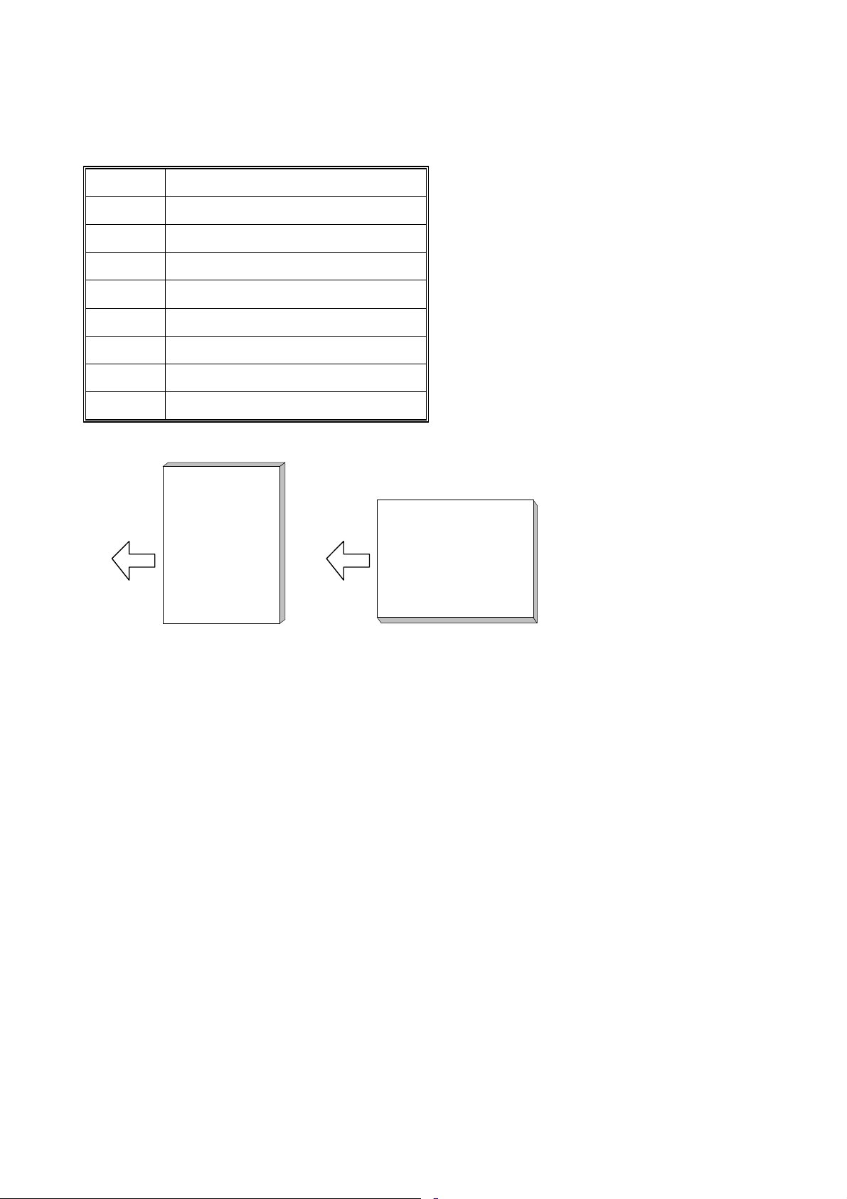
LEF (Long Edge Feed) SEF (Short Edge Feed)
LEFSEF.WMF
Page 12

SECTION 1
OVERALL INFORMATION
Page 13

Page 14

1. OVERALL MACHINE INFORMATION
1.1 SPECIFICATIONS
1.1.1 COPIER ENGINE
Configuration: Console
Copy Process: Dry electrostatic transfer system
Originals: Sheet/Book/Object
Max.: A3/11" x 17" Original Size:
Min.: A5, 51/2" x 81/2" (with ADF)
Original Alignment: Rear left corner (for platen mode, ADF mode)
Paper Weight: Tray 1~3:
Tray 6 (LCT):
Tray 4~5 (LCT):
Tray 7 (Bypass):
Duplex Tray
(Possible
Weight):
Paper Size: Tray 1 (Tandem): 81/2" x 11" LEF, A4 LEF
Tray 2, Tray 3:
Duplex Tray
(Possible Sizes):
Reproduction Ratios: 7 reduction and 5 enlargement
Enlargement 400%
Full Size
Reduction
52 to 163 g/m2
Bond: 16 to 40 lb.
Cover: 50 to 60 lb.
Index: 90 lb.
52 to 216 g/m2
Bond: 16 to 40 lb.
Cover: 50 to 60 lb.
Index: 90 to 110 lb.
64 to 163 g/m2
Bond: 20 to 40 lb.
Cover: 50 to 60 lb.
Index: 90 lb.
51/2" x 81/2" to 11" x 17", 12" x 18"
A5 to A3
A5 to A3, 51/2" x 81/2" to 11" x 17",
12" x 18"
Metric Version Inch Version
400%
200%
141%
122%
115%
100% 100%
93%
82%
75%
71%
65%
50%
25%
200%
155%
129%
121%
93%
85%
78%
73%
65%
50%
25%
PTM 1-1 B070/B071
Page 15

Zoom:
25 ~ 400% (allows manual adjustment in 1% steps
vertically, horizontally)
Copy Speed:
900/1050 75 ppm
900 90 ppm
1050 105 ppm
Copying with image stored in
memory with A4/LT LEF feeding
from the same tray.
When using ADF 1-to-1 with
A4/LT LEF magnification feeding
from the same tray.
Resolution Scanning 600 dpi
Printing 1200 dpi
Gradation: 256 levels Scanning (8 bits/pixel)
Printing (1 bit/pixel, 9
values):
Warm-up Time:
Less than 360 s from Off mode at 23°C (73.4°F)
First Copy Time Copy Tray 1, A4/81/2" x 11" LEF
Face-up Less than 3.5 s Less than 3.2 s
Face-down Less than 5.0 s Less than 4.2 s
900 (90 cpm) 1050 (105 cpm)
Copy Number Input: 1 to 9999
Copy Paper Capacity
(Sheets):
Copier 3,000
LCT 4,550
Bypass 500
Total 8,050
Tray 1: (Tandem) 1000 x 2
Tray 2: 500
Tray 3: 500
Tray 4: 1,000 , Tray 5: 1,000, Tray 6:
2,550
Tray 7, 500 (Optional Bypass Tray B512)
Memory Capacity: RAM; 256 MB (128 x 2) Standard
256 MB (Optional, Required for Scanner/Printer
Option)
HDD; 80 GB (40 GB x2), approximately 1,735 copies
Toner Replenishment: Cartridge exchange (1,450 g/cartridge)
Toner Yield:
55 K copies, (A4 LEF, 6% chart, B070 (90 cpm) 1 to 25
Repeat Copying), (B071 (105 cpm), 1 to 50 Repeat
Copying)
Power Source: North America; 208 to 240 V, 60 Hz, 20 A
Europe/Asia; 220 to 240 V, 50/60 Hz, 16 A
Dimensions
(W x D x H)
Full System;
Copier;
870 x 858.5 x 1476 mm
32.3" x 33.8" x 58.1"
2218 x 8585 x 1476 mm
87.3" x 33.8" x 58.1"
Weight: Less than 275 kg (605 lb.) including ADF, and no options
B070/B071 1-2 PTM
Page 16

Space Requirements:
Copier (w x d) 1202 x 858.5 mm (47.3" x 33.8")
Full System
(w x d)
Full System: Mainframe + ADF + Finisher B478 + LCT B511 + Cover Interposer Tray B470
*1
Max.
Min.
+ Bypass Tray B512
2528 x 858.5 mm
"
99
x 33.7"
2804 x 858.5 mm
"
110.4
x 33.7"
Finisher + Bypass with bypass
tray extended for A3 SEF
Finisher + Bypass with bypass
tray extended for A4 LEF.
Power Consumption: North America Version
Mainframe Only Full System*
(Unit: W)
900 1050 900 1050
Warm-up 2.20 K 2.20 K 2.30 K 2.30 K
Stand-by 0.65 K 0.65 K 0.70 K 0.70 K
Copying 2.70 K 2.80 K 2.80 K 2.90 K
Maximum 2.80 K 2.90 K 2.90 K 3.00 K
*Full System: Mainframe + ADF + LCT + Bypass Tray + Cover Interposer + Finisher1
1
Finisher: B478 + Punch Unit with B071 (105 cpm), B468 + Punch Unit with B070
(90 cpm)
Noise Emission
900 (90 cpm)
Mainframe
Full System
1050 (105 cpm)
Mainframe
Full System
Sound Power
Level db (A)
Stand-by 60 45
Copying 74 60
Stand-by 59 46
Copying 78 68
Sound Power
Level dB (A)
Stand-by 60 45
Copying 76 61
Stand-by 59 46
Copying 79 68
Sound Pressure
Level dB (A)
Sound Pressure
Level dB (A)
PTM 1-3 B070/B071
Page 17

1.1.2 ADF
Original Size:
Original Weight:
Normal Original Mode: A3 to B5, 11" x 17" to 51/2" x
Thin Original Mode A3 to B5, 11" x 17" to 51/2" x
Duplex Original Mode: A3 to B5, 11
"
8
1/2
"
8
1/2
"
8
1/2
"
Normal Original Mode: 52~128 g/m2 (Note 1)
Thin Original Mode 40~128 g/m2 (Note 1)
Duplex Original Mode: 52~105 g/m
2
Table Capacity: 100 sheets (80 g/m2, 20 lb)
Original Feeding Speed: 75 cpm (A4/81/2" x 11" LEF, 1 to 1)
Original Standard Position: Rear left corner (Face-up)
Separation: FRR
Original Transport: One flat belt
Original Feed Order: From the top original
Power Source: DC 24 V and DC 38 V from the copier
Power Consumption: Less than 130 W
Dimensions (W x D x H): 680 x 560 x 150 mm (26.8" x 22" x 5.9")
Weight Less than 17.5 kg (38.5 lb.)
Note 1:156 g/m
Note 2:128 g/m
2
possible, but not guaranteed.
2
possible, but not guaranteed.
x 17" to 51/2" x
(Note 2)
B070/B071 1-4 PTM
Page 18
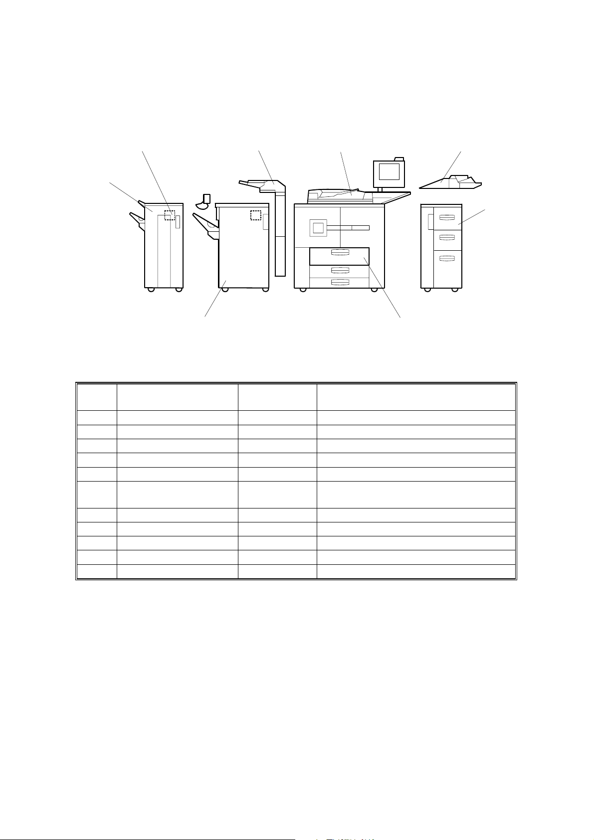
1.2 MACHINE CONFIGURATION
7
6
10
1
2
3
5
4
B070I413.WMF
No. Item
1 Mainframe eStudio900/1050 900 (90 cpm), 1050 (105 cpm).
2 Bypass Tray MY1024
3 LCT MP4501
4 A3/DLT Tray Kit*1 KF9000 Replace Tray 1 (tandem tray) inside.
5 3000 Sheet Finisher MJ1026
3000 Sheet Booklet
6
Finisher
7 Punch Unit N/A
8 Output Jogger Unit KK9000 Attached to Finisher
9 Cover Interposer Tray MJ7002 Attached to Finisher.
10 Punch Unit MJ6006 Inside Finisher
Copier Connection Kit GE1130 Not shown.
*1
: Replaces Tandem Tray in main unit.
Machine
Code
N/A
Comments
PTM 1-5 B070/B071
Page 19
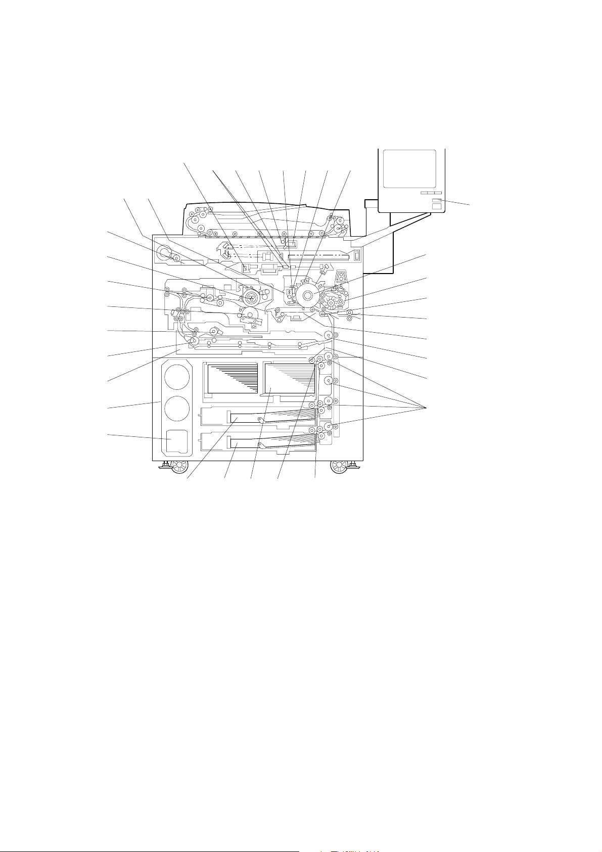
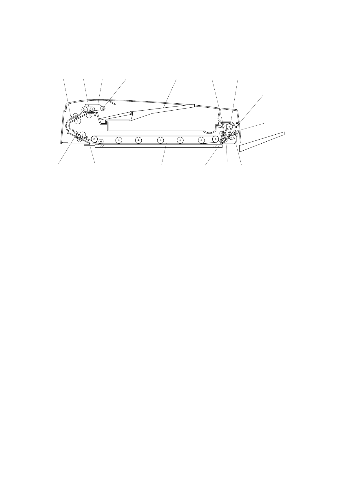
1.3 COMPONENT LAYOUT
1.3.1 COPIER ENGINE
31
30
29
28
27
26
25
24
23
6 753 41 2
8
33 32
9
10
11
12
13
14
15
16
17
22 21 20 19 18
1. Laser Diode Board
2. fθ Lenses
3. Sensor Board Unit
4. Exposure Lamp
5. Cleaning Brush
6. Lamp Regulator
7. Cleaning Blade
8. Charge Corona Unit
9. Color LCD
10. Drum
11. Development Unit
12. Registration Roller
13. LCT Relay Roller
14. Transfer Belt Unit
15. Relay Roller
16. Pick-up Roller
17. Vertical Transport Rollers
B070D870.WMF
18. Separation Roller
19. Feed Roller
20. 1st Tray (Tandem, 1,000 sheets each)
21. 3rd Tray (500 sheets)
22. 2nd Tray (500 sheets)
23. Used Toner Bottle
24. Toner Bank Unit
25. Duplex Tray
26. Inverter Unit Paper Exit Roller
27. Inverter Feed Roller
28. Pressure Roller
29. Paper Cooling Pipe
30. Hot Roller
31. Motor Control Unit
32. Oil Supply & Cleaning Web
33. Drum Unit
B070/B071 1-6 PTM
Page 20
1.3.2 ADF
Overview
1 2
3
4
5
6
15
14
13
12
11
1. Entrance Sensor 9. Feed-out Roller
2. Separation Roller 10. Exit Junction Gate
3. Feed Belt 11. Inverter Roller
4. Pick-up Roller 12. Exit Sensor
5. Original Tray 13. Transport Belt
7
8
9
B070D869.WMF
10
6. Inverter Junction Gate 14. Registration Sensor
7. Inverter Guide Roller 15. Width Sensors (x3)
8. Inverter Sensor
PTM 1-7 B070/B071
Page 21
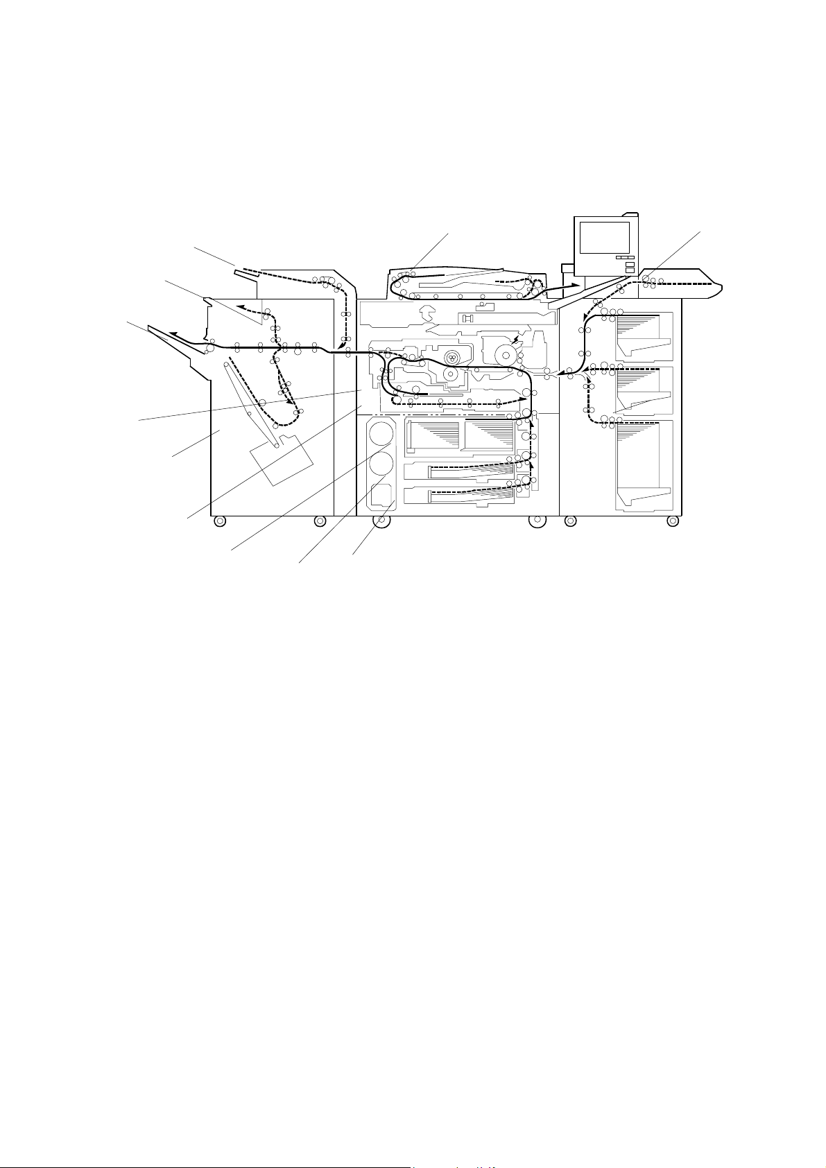
1.4 PAPER PATH
10
9
11
8
12
7
6
5
1
2
3
4
B070D871.WMF
1. ADF
2. Bypass Tray
3. Optional LCT
4. Tray 3
5. Tray 2
6. Tray 1
7. Duplex Unit
8. Optional Finisher
9. Inverter Unit
10. Shift Tray
11. Upper Tray
12. Cover Interposer
B070/B071 1-8 PTM
Page 22
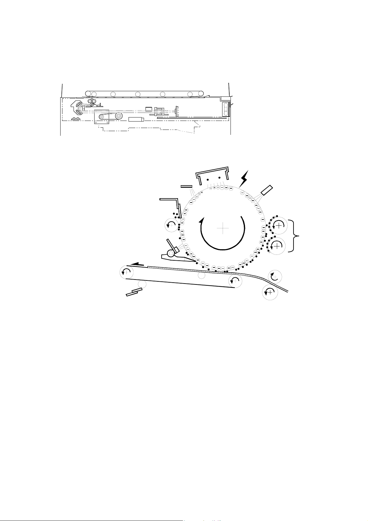
1.5 COPY PROCESS
1
B070D872.WMF
2
10
3
4
9
8
7
6
B070D873.WMF
1. EXPOSURE
A xenon lamp exposes the original. Light reflected from the original passes to
the CCD, where it is converted into an analog data signal. This data is
converted to a digital signal, processed, and stored in the memory. At the time
of printing, the data is retrieved and sent to the laser diode. For multi-copy runs,
the original is scanned once only and stored to the hard disk.
5
2. DRUM CHARGE
An OPC (organic photoconductor) drum is used in this machine. In the dark,
the charge corona unit gives a negative charge to the drum. The grid plate
ensures that corona charge is applied uniformly. The charge remains on the
surface of the drum because the OPC layer has a high electrical resistance in
the dark.
PTM 1-9 B070/B071
Page 23

3. LASER EXPOSURE
The processed data from the scanned original is retrieved from the hard disk
and transferred to the drum by four laser beams, which form an electrostatic
latent image on the drum surface. The amount of charge remaining as a latent
image on the drum depends on the laser beam intensity, which is controlled by
the laser diode board (LDB).
4. DRUM POTENTIAL SENSOR
The drum potential sensor detects the electric potential on the drum to correct
various process control elements.
5. DEVELOPMENT
The magnetic developer brush on the development rollers comes in contact
with the latent image on the drum surface. Toner particles are electrostatically
attracted to the areas of the drum surface where the laser reduced the negative
charge on the drum.
6. IMAGE TRANSFER
Paper is fed to the area between the drum surface and the transfer belt at the
proper time to align the copy paper and the developed image on the drum.
Then, the transfer bias roller and brush apply a high positive charge to the
reverse side of the paper through the transfer belt. This positive charge pulls
the toner particles from the drum to the paper. At the same time, the paper is
electrically attracted to the transfer belt.
7. PAPER SEPARATION
Paper separates from the drum as a result of the electrical attraction between
the paper and the transfer belt. The pick-off pawls also help separate the paper
from the drum.
8. ID SENSOR
The laser forms a sensor pattern on the drum surface. The ID sensor measures
the reflectivity of the pattern. The output signal is one of the factors used for
toner supply control.
9. CLEANING
The cleaning brush removes toner remaining on the drum after image transfer
and the cleaning blade scrapes off all remaining toner.
10. QUENCHING
The light from the quenching lamp electrically neutralizes the charge on the
drum surface.
B070/B071 1-10 PTM
Page 24

SECTION 2
DETAILED DESCRIPTIONS
Page 25

Page 26
2. DETAILED SECTION DESCRIPTIONS
2.1 DOCUMENT FEEDER
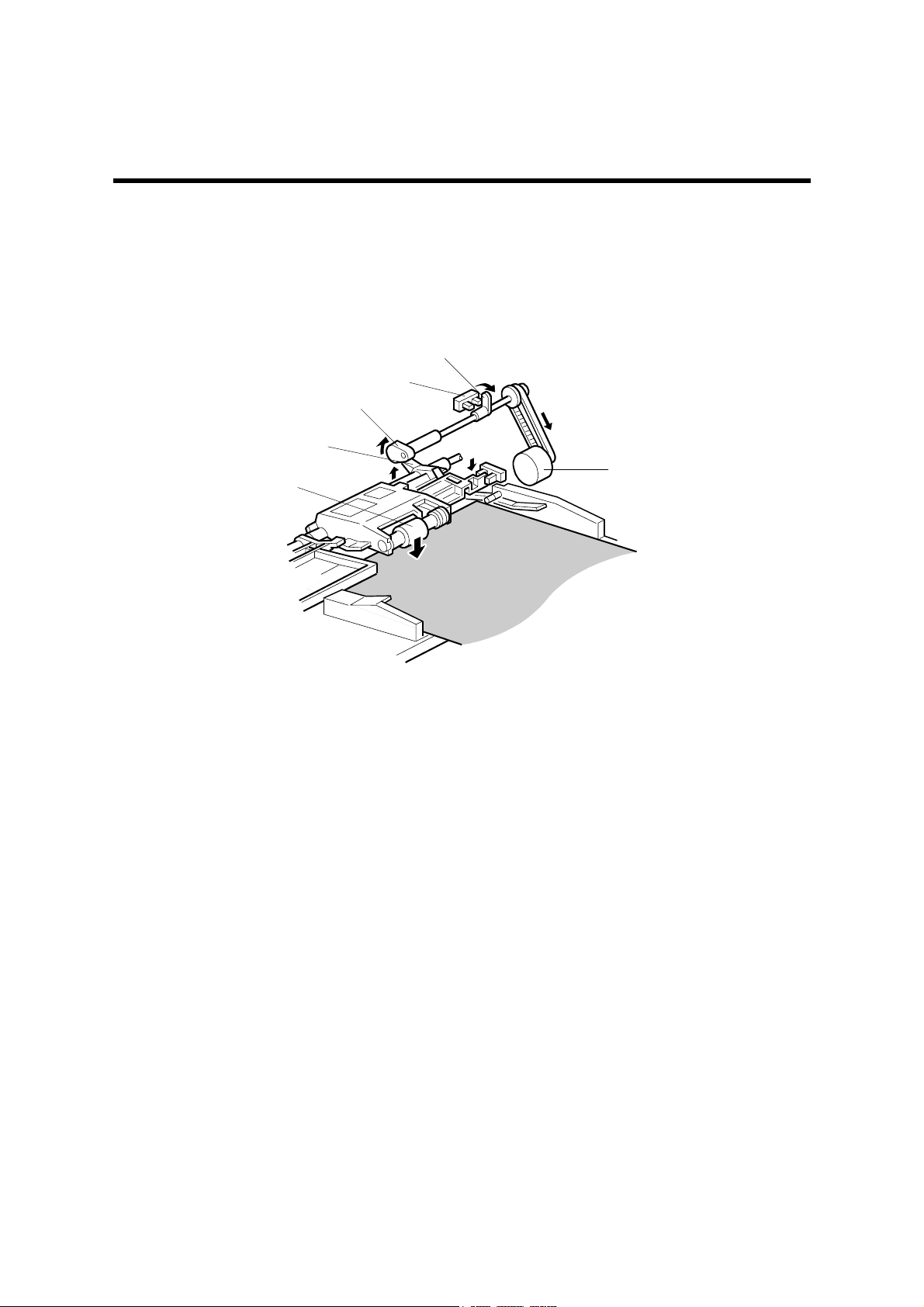
2.1.1 PICK-UP ROLLER RELEASE
[B]
[C]
[D]
[F]
[E]
[A]
B070D916.WMF
When the original set sensor is off (no original on the original tray), the pick-up roller
stays in the up position.
When the original set sensor turns on (or when the trailing edge of a page passes the
entrance sensor while pages remain on the original tray), the pick-up motor [A] turns
on. The cam [B] rotates away from the pick-up roller release lever [C]. The lever then
rises and the pick-up roller [D] drops onto the original.
When the original reaches the entrance sensor, the pick-up motor turns on again. The
cam pushes the lever down, and the pick-up roller rises until the pick-up roller HP
sensor [E] detects the actuator [F].
PTM 2-1 B070/B071
Page 27
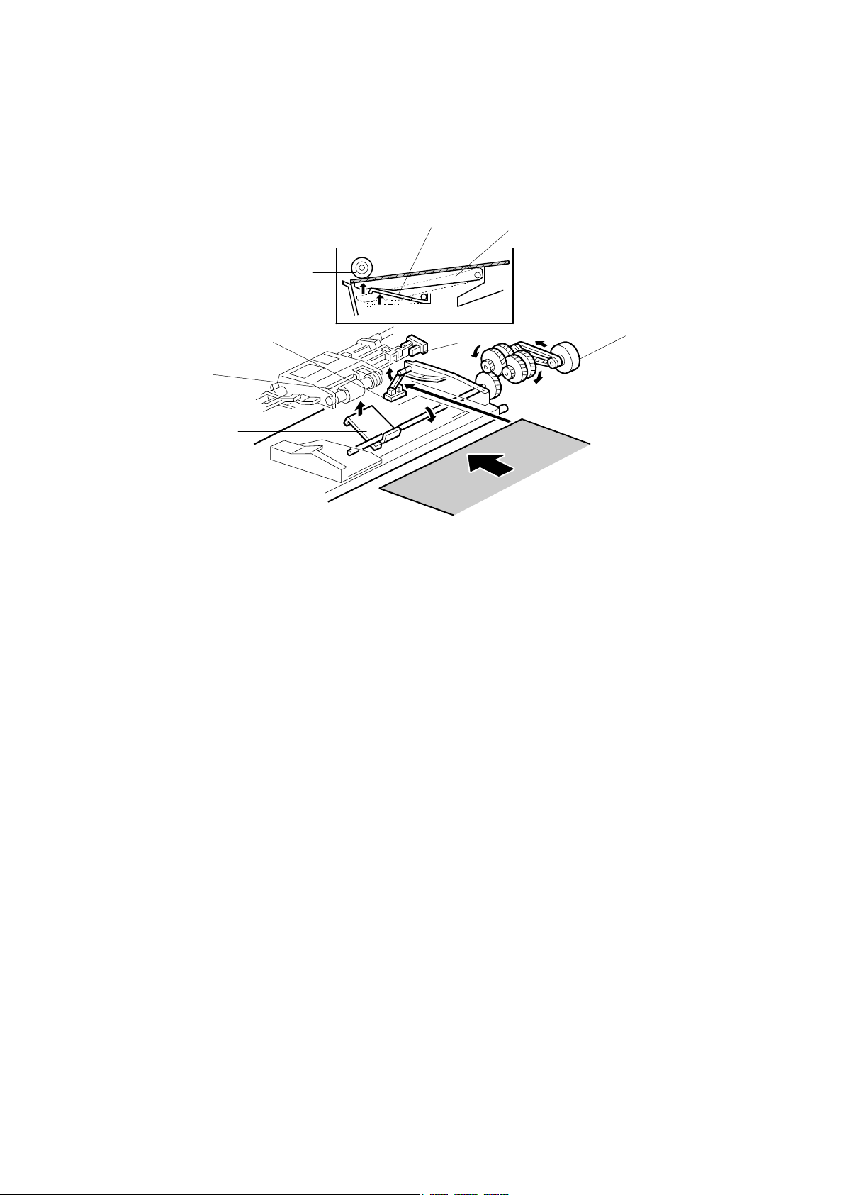
2.1.2 BOTTOM PLATE LIFT
[F]
[E]
[B]
[A]
[C]
[D]
[B]
[F]
B070D917.WMF
When an original is placed on the original tray, the original set sensor [A] turns on, the
pick-up roller [B] drops on to the original, and the bottom plate position sensor [C]
turns off. Then the bottom plate motor [D] turns on and lifts the bottom plate [E] by
raising the lift lever [F] until the bottom plate position sensor turns on.
The level of the pick-up roller drops as the stack of originals becomes smaller, and
eventually, the bottom plate position sensor [C] turns off. Then, the bottom plate motor
turns on and lifts the bottom plate until the bottom plate position sensor turns on. This
keeps the original at the correct height for feeding.
PTM 2-2 B070/B071
Page 28
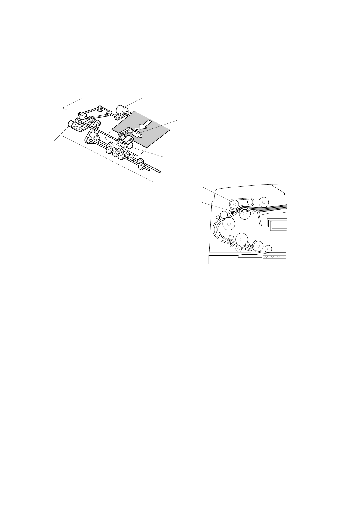
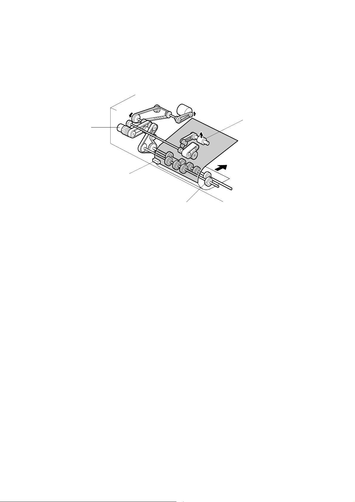
2.1.3 PICK-UP AND SEPARATION
[D]
[A]
[E]
[B]
[C]
[A]
B070D918.WMF
[B]
[C]
B070D919.WMF
The original separation system is a Feed and Reverse Roller (FRR) system. The pickup roller [A], feed belt [B], and separation roller [C] are driven by the feed-in motor [D].
To drive this mechanism, the feed-in motor [D] and feed-in clutch [E] turn on.
(
Handling Paper> Handling Originals> Document Feed> FRR with Feed Belt)
PTM 2-3 B070/B071
Page 29
2.1.4 ORIGINAL FEED
[D]
[B]
[A]
[C]
B070D920.WMF
When the leading edge of the original turns the entrance sensor [A] on, the feed-in
clutch [B] turns off and the drive for the feed belt is released. The original is fed by the
transport rollers [C].
At the same time, the pick-up motor starts again and the pick-up roller [D] is lifted up.
When the pick-up roller HP sensor turns on, the pick-up motor stops (see Pick-up
Roller Release).
PTM 2-4 B070/B071
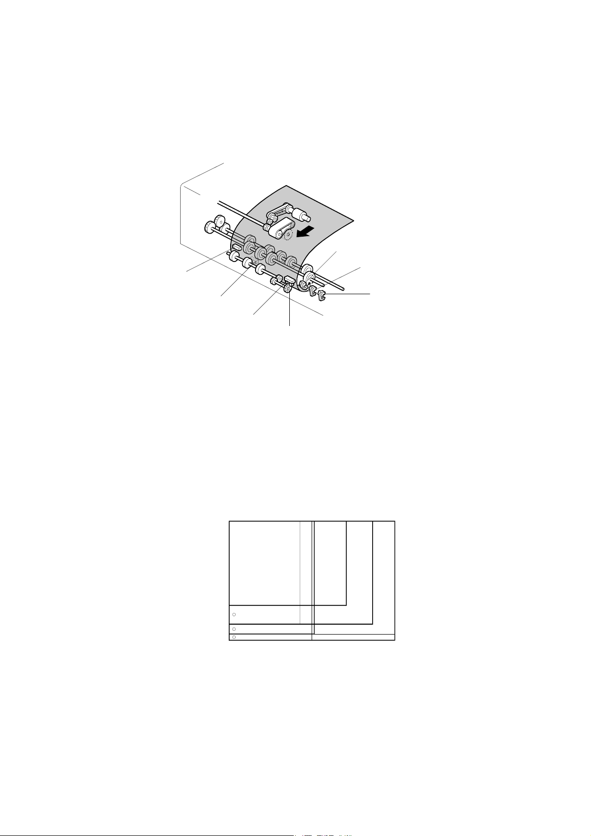
Page 30
2.1.5 ORIGINAL SIZE DETECTION
[B]
[G]
[C]
[F]
[D]
[A]
B070D921.WMF
[E]
The ADF detects the original size by combining the readings of original length sensor
[A], and original width sensors-1 [B], -2 [C], and -3 [D].
Original Length
The original length sensor and the disk [E] (connected to the transport roller) generate
a pulse signal. The CPU counts pulses, starting when the leading edge of the original
turns on the registration sensor [F], until the trailing edge of the original turns off the
entrance sensor [G].
Original Width
The CPU detects original width using three original width sensors -1, -2, -3 as shown
above. Three small circles on the diagram indicate the positions of the sensors.
Original Width Sensor Location
A4 SEF
B 4/B5 L EF
DLT/LT LEF
A 3/A4 L EF
B070D922.WMF
Detectable Paper Sizes
Please refer to the “1.2 ADF” table in “Specifications”.
PTM 2-5 B070/B071
Page 31

2.1.6 ORIGINAL TRANSPORT
[B]
[A]
[C]
B070D923.WMF
[E]
[D]
3.5 mm
B070D924.WMF
The transport belt [A] is driven by the transport belt motor [B]. The transport belt motor
starts when the copier sends an original feed-in signal.
The pressure rollers inside the transport belt maintain the correct pressure between
belt and original. The pressure roller [C] closest to the left original scale is made of
rubber for the stronger pressure needed for thick originals. The other rollers are
sponge rollers.
Normally, originals are manually placed at the left rear corner, so an original [D] fed
from the ADF must also be at this position. But if the original touches the rear scale [E]
as it feeds, original skew, jam, or wrinkling may occur.
To prevent such problems, the original transfer position is set to 3.5 mm away from
the rear scale as shown. The 3.5 mm gap is compensated for by changing the starting
position of the main scan for when the image is exposed on the drum.
PTM 2-6 B070/B071
Page 32

2.1.7 ORIGINAL SKEW CORRECTION
[A]
7 mm
B070D925.WMF
The transport belt motor remains energized to carry the original to the right about 7
mm past the left scale [A]. Then the motor stops and reverses to feed the original 12
mm to the left against the left scale to correct skew. This forces the original to hit the
left scale, which aligns the trailing edge to minimize original skew on the exposure
glass.
If thin original mode is selected, the original is not forced back against the left scale.
This is to prevent damage to the original.
After a two-sided original has been inverted to copy the 2nd side, it is fed in from the
inverter against the left scale [B] without skew correction.
NOTE: The bottom drawing applies to duplex scanning; the top two drawings do not
The amount of reverse feed against the left scale can be adjusted as follows:
[B]
apply in this mode.
• One-sided originals, and side 1 of two-sided originals: SP6006-3 (DF Registration
Adjustment – Leading Edge Duplex 1st)
• Side 2 of two-sided originals: SP6006-4 (DF Registration Adjustment – Leading
Edge Duplex 2nd).
PTM 2-7 B070/B071
Page 33

2.1.8 ORIGINAL INVERSION AND FEED-OUT
General Operation
[A]
B070D926.WMF
When the scanner reaches the return position, the copier CPU sends the feed-out
signal to the ADF. When the ADF receives the feed-out signal, the transport belt motor
and feed-out motor [A] turn on. The original is then fed out to the exit tray or fed back
to the exposure glass after reversing in the inverter section.
This ADF has two exit trays. For single-sided original mode, the original is fed out
straight out to the right exit tray, but for double-sided original mode, the original is fed
out to the upper exit tray.
This causes the originals to be fed out in the correct order on the exit trays and allows
the maximum one-to-one copy speed for each mode.
PTM 2-8 B070/B071
Page 34

Original Inversion
[F]
[B]
[E]
[G]
[D]
[A]
[C]
B070D927.WMF
When the ADF receives the original invert signal from the copier, the transport belt
motor, feed-out motor, exit gate solenoid [A], and inverter gate solenoid [B] turn on
and the original is fed back to the exposure glass through the inverter roller [C], exit
gate [D], inverter guide roller [E], inverter gate [F], and inverter roller.
The transport belt motor reverses shortly after the leading edge of the original turns on
the inverter sensor [G], and feeds the original to the left scale.
PTM 2-9 B070/B071
Page 35

Original Exit (Single-Sided Original Mode)
[B]
[A]
[C]
B070D928.WMF
The exit gate solenoid [A] remains off, the exit gate [B] remains closed, and the
original is fed out to the right exit tray.
The speed of the motor is reduced about 30 mm from the trailing edge of the original
to ensure the originals stack neatly on the exit tray. This timing is determined by the
length of the original, and the time since the exit sensor [C] detected the leading edge.
The transport belt motor turns off after the exit sensor [C] turns off.
PTM 2-10 B070/B071
Page 36

Original Exit (Double-Sided Original Mode)
[C]
[E]
[A]
[B]
[D]
B070D929.WMF
The exit gate solenoid [A] turns on and the exit gate [B] opens.
The inverter gate solenoid [C] remains off, and the original is fed out to the upper tray.
The transport belt motor turns off when the trailing edge of the original passes the exit
sensor [D].
To stack the originals neatly on the upper tray, the feed-out motor speed is reduced
shortly after the trailing edge of the original turns off the inverter sensor [E].
PTM 2-11 B070/B071
Page 37

2.2 SCANNING
2.2.1 OVERVIEW
1
2
3
4
5
13
12
6
8
7
9
B070D001.WMF
11
1. Scanner Motor 10. LCDC (LCD Control Board)
2. White Plate (on exposure glass) 11. CCD (Charge Coupled Device)
3. 2nd Mirror 12. Original Length Sensor (APS)
4. Exposure Lamp (Xenon) 13. Scanner Lens
5. Exposure Glass 14. 3rd Mirror
6. 1st Mirror 15. Original Width Sensors 1, 2, 3 (APS)
10
7. Lamp Regulator 16. Scanner HP Sensor
8. SBU Cooling Fan 17. Optics Anti-condensation Heater (option)
9. Optics Cooling Fan
One xenon lamp (23W) as the exposure lamp [4] illuminates the original. The image is
reflected onto the CCD [11] (600 dpi resolution) via the 1st, 2nd, and 3rd mirrors, and
through the lens [13].
The lens, CCD, and SBU are in a single unit, the lens block. The optical axis, focus,
and MTF are pre-adjusted, so this lens block requires no adjustment in the field. The
1st scanner consists of the exposure lamp [4], the lamp regulator [7] and the 1st
mirror.
Two fans, the optics cooling fan [9] and the SBU cooling fan [8], draw cool air into the
scanning unit. The optics cooling fan turns on when the scanner motor starts and turns
off 10 seconds after the scanner motor turns off. The SBU cooling fan operates while
the operation switch is on. The optional optics anti-condensation heater [17] (if
installed as an option) turns on while the main switch is off, to prevent moisture from
forming on the optics.
PTM 2-12 B070/B071
Page 38

2.2.2 SCANNER DRIVE
[C]
[D]
[E]
[B]
[A]
[F]
[G]
B070D003.WMF
The scanner motor is a dc servo motor. The 1st and 2nd scanners [A, B] are driven by
the scanner motor [C] through the timing belt [D], scanner drive pulley [E], scanner
drive shaft [F], and two scanner wires [G].
The MCU (Motor Control Unit) board controls the scanner motor. The exposure lamp
scans a sheet with 100% magnification at 515 mm/s and returns to the scan position
for the next scan at 2500 mm/s.
Magnification and Reduction
Magnification and reduction in the main scan direction are done in the IPU board.
Magnification and reduction in the sub scan direction, however, are done by
controlling the speed of the scanner motor in sync with the main scan processing done
in the IPU.
• Magnification above 101% is done in the IPU. For example, at 200% magnification,
the IPU doubles magnification while the scanner motor speed remains at 100%.
• Reduction in the range 51% to 100% is done by the scanner motor.
•
Reduction in the range 25% to 50% is done by the scanner motor, assisted by IPU
processing. For example, at 40% reduction, the scanner motor speed is 80% and
the IPU reduces the image by 1/2.
• Reduction below 25% is done by the scanner motor, assisted by IPU processing.
For example, at 24% reduction the scanner motor speed is 96% and the IPU
reduces the image by 1/4.
NOTE: Magnification in the sub scan direction can be adjusted by changing the
scanner motor speed with SP4008 (Scanner Sub Scan Magnification).
PTM 2-13 B070/B071
Page 39

2.2.3 ORIGINAL SIZE DETECTION
[F]
[G]
[A]
B070D052.WMF
[B]
[C]
[D]
[E]
B070D535.WMF
There are three reflective sensors at three locations in the optics cavity for original
size detection.
The original width sensor [A] detects the original width, and the original length sensor
1 [B] and original length sensor 2 [C] detect the original length. These are the APS
(Auto Paper Select) sensors.
Inside each APS sensor, there is an LED [D] and either three photoelectric devices [E]
(for the width sensor) or one photoelectric device (for each length sensor). In the width
sensor, the light generated by the LED is separated into three beams and each beam
scans a different point of the exposure glass (in each length sensor, there is only one
beam). If the original or ADF cover is present over the scanning point, the beam is
reflected and each reflected beam exposes a photoelectric device and activates it.
While the main switch is on, these sensors are active and the original size data is
always sent to the main CPU. However, the main CPU checks the data only when the
ADF is being closed.
The ADF functions as the platen. The DF position sensor [F] (attached to the ADF)
detects whether the ADF is open or closed.
The APS start sensor [G] triggers auto paper size detection.
PTM 2-14 B070/B071
Page 40

NOTE: The Europe/Asia model has one length sensor (L1), but the North American
A4/A3 Version LT/DLT Version 2 1 1 2 3
:High (Paper Present) L: Low
H
model has two length sensors (L1, L2)
Original Size
A3 11" x 17"
B4 10" x 14"
F4 81/2" x 14" (8" x 13")
A4 SEF 8
B5 SEF —
A5 SEF 51/2" x 81/2"
A4 LEF 11" x 81/2"
B5 LEF —
A5 LEF 81/2" x 51/2"
1/2
" x 11"
Length
Sensor
H
H H H
Width Sensor
H
H H H H L
H H H L L
L
H H L L
L H L L L
L L L L L
L L H H
H
L L H H L
L L H
L
L
SP4301
Display
00011111
00011110
00011100
00001100
00001000
00000000
00000111
00000110
00000100
The original size data is taken by the main CPU when the DF position sensor is
activated. This is when the ADF is positioned about 12 cm above the exposure glass.
At this time, only the sensor(s) underneath the original receive the reflected light and
switch on. The other sensor(s) are off. The main CPU recognizes the original size
from the on/off signals from the five sensors.
If the copy is made with the ADF open, the main CPU decides the original size from
the sensor outputs when the Start key is pressed.
The above table shows the outputs of the sensors for each original size. This original
size detection method eliminates the necessity for a pre-scan and increases the
machine productivity.
0,0
Width Sensor 1
Width Sensor 2
Width Sensor 3
PTM 2-15 B070/B071
A5 SEF
B5 SEF
Length Sensor 1
A5 LEF
A4 LEF
A4 SEF
Length Sensor 2
B4
A3
B070D931.WMF
Page 41

2.3 IMAGE PROCESSING
2.3.1 IMAGE PROCESSING STEPS AND RELATED SP MODES
The following tables describe the image processing path and the related SP modes
used for each image processing mode.
The user can adjust many of the image processing parameters with a UP mode
(Copy/Document Server Features> General Features> Original Mode Quality Level),
using fixed settings such as Sharp, Normal, and Soft. Each of these fixed settings
have different parameters, but user changes do not affect the relevant SP mode
settings.
If the user is not satisfied with any of the available settings for this UP mode, the
technician can adjust the SP modes. However, the SP mode settings are not used
unless the user selects ‘Service Mode’ with the UP Mode.
Text
Text/Photo
Photo
Pale
Generation
Soft
Photo Priority
Screened Printed
Soft
Soft
Normal
Normal
Normal
Normal
Normal
Sharp
Text Priority
Glossy Phot
Sharp
Sharp
Service Mode
Service Mode
Service Mode
Service Mode
Service Mode
B070D011.WMF
PTM 2-16 B070/B071
Page 42

2.3.2 IMAGE PROCESSING OVERVIEW
CCD
Polygon Motor
OPC
SBU
IPUBCU
LDB
PCI BUS
Controller
HDD
Key
Data flow
Signal flow
B070D934.WMF
SBU: Photoelectric conversion, Odd/even allocation, Amplification, A/D
Conversion (analog to digital), Light intensity detection (scanning)
BCU: Engine control, Scanner control, SBU settings, IPU settings, LDB
settings
IPU: Shading correction, Image Processing, Main/Sub scan
magnification, Video path switching, Image Compression/
Decompression. The GAVD on this board performs density
conversion processing, FCI processing, and edge processing, and
also generates the test patterns.
Controller: System control, software application control, image storage control,
file compression/decompression
LDB: 8-beam laser exposure, binary-to-grayscale conversion,
synchronization detection
PTM 2-17 B070/B071
Page 43

2.3.3 IMAGE PROCESSING FLOW
Image processing is done by the IPU (Image Processing Unit), following the steps
shown below.
Overall image processing for this machine is designed to:
• Target edges with filters to improve the angles of text characters and reduce the
occurrence of moiré filled areas.
•
Improve the evenness of granular areas in images
Shading Correction
Ð
Gamma Correction Background erase
Ð
Pre-Filter Reduces the occurrence of moiré.
Ð
Main Scan Magnification
Ð
Auto Select
Ð
Filtering
Ð
Independent Dot Erase Removes isolated pixels.
Ð
Line Width Correction
Ð
Density Control
Ð
Grayscale Processing
Ð
Video Path
Ð
LD Unit
Corrects the dispersion of the scanning
lens and CCD.
Determines if an image is text or raster
image data and processes the data
accordingly.
Selects the best methods for Filtering,
Density Control, and Grayscale
Processing.
MTF and smoothing (MTF filter of
previous machines)
Either of two filters is selected by Auto
Select above.
Employs one of two gamma tables,
selected by Auto Select above
Error diffusion, dithering, or binary picture
processing
Black-and-white digitization or dithering is
selected by “Auto Select above.
ÍÎ
Application (printer)
PTM 2-18 B070/B071
Page 44

PTM 2-19 B070/B071
Page 45

2.3.4 IMAGE PROCESSING MODES
The user can select one of the following five modes with the User Tools screen: Text,
Text/Photo, Photo, Pale, Generation.
Each mode has four different settings (described below). Each mode has a Custom
Setting that can be customized with SP modes to meet special requirements that
cannot be covered by the standard settings.
NOTE:
Tex/Photo
Generation
To see these settings in the User Tools mode, press the User Tools key, press
“Copier/Document Server Functions”, then press “Copy Quality”.
Mode Setting Function
Soft Rough texture background drops out.
Used for black-and-white printed material and
Text
Photo
Pale
Copy
Normal
Sharp
Custom
Setting
Photo Priority
Normal
Text Priority
Custom
Setting
Print Photo
Normal
Glossy Photo
Custom
Settings
Soft
Normal
Sharp
Custom
Setting
Soft Used to achieve an image smoother than Normal.
Normal
Sharp
documents that contain mainly text. Easily reads lines
as well as text.
Use for newspapers, time schedules, or any type of
printed material with fine print. Emphasizes black over
white.
Stores SP command settings.
Used for documents that contain text and color or blackand-white photos, such as catalogs, magazines, maps,
etc. Provides more faithful reproduction than the Text
mode.
Stores SP command settings.
Used for magazines, graphics, for smooth reproduction.
Employs dithering.
Used for copying photographs, graphics, for sharp
reproduction. Employs error diffusion.
Used for best results in copying glossy photographs for
sharp reproduction. Employs error diffusion.
Stores SP command settings. Employs either error
diffusion or dithering, depending on an SP setting.
Used for low density documents with text handwritten in
black or color pencil (or carbon copies) such as
receipts, invoices, etc.
Stores SP command settings.
Used to achieved best reproduction of “copies of
copies” by smoothing the image.
Used to emphasize lines and text stronger than Normal
for better image quality.
PTM 2-20 B070/B071
Page 46

Custom
Background
Dropout
Setting
Strong
Medium
Weak
Stores SP command settings.
Drops out the blue background color of tab sheets or
other paper.
Drops out the green background color of tab sheets or
other paper.
Drops out the orange background color of tab sheets or
other paper.
PTM 2-21 B070/B071
Page 47

2.3.5 IMAGE QUALITY SP ADJUSTMENTS
Adjustments are easier with this machine, because the parameters have been
grouped and no longer have to be adjusted one by one.
In this section, we will cover the custom settings for each of the 5 original modes:
These custom settings are:
•
Image Quality
•
Line Width Correction
Settings adjustable for each original mode will also be covered (these do not just
affect the custom settings; they also affect all sub original modes, such as sharp text).
•
Independent Dot Erase
• Background Erase
Custom Settings for Each Mode: Image Quality
Custom Setting: Text Mode Image Quality
Item Range Default SP No.
25~55% SP4903 001
55.5~75% SP4903 002
Text
75.5~160% SP4903 003
160.5~400
%
If the value is increased, the outlines of lines become sharper but this could cause
moiré to appear in dot patterns. If the value is decreased, image patterns become
smoother, the occurrence of moiré decreases, but the corners of characters and
intersections of lines at acute angles may not be as sharp.
There are two sets of custom settings for photo mode. One is for dithering, and one is
for error diffusion. The set of custom settings that will be used depends on the setting
of SP4904 002. The possible settings are:
0~10 5 Normal
SP4903 004
0 Dither (106 line)
1 Dither (141 line)
2 Dither (212 line)
3 Error Diffusion
PTM 2-22 B070/B071
Page 48

Custom Setting: Photo Mode (Dithering) Image Quality
Item Range Default SP No.
25~55% SP4903 005
55.5~75% SP4903 006
Photo
75.5~160% SP4903 007
160.5~400
%
0~6 3 Print Photo
SP4903 008
Used for coarse, dithered tone photographs such as newsprint.
If the value is increased, the photo becomes sharper, but blurring could occur in the
sub scan direction. If the value is decreased, blurring in the sub scan direction is less
obvious but outlines become fuzzy.
Custom Setting: Photo Mode (Error Diffusion) Image Quality
Item Range Default SP No.
25~55% SP4903 009
55.5~75% SP4903 010
0~6 1 Normal
SP4903 012
Photo
75.5~160% SP4903 011
160.5~400
%
Used for printed materials (magazines, etc.) with photographs to sharp patterns in
copies.
If the photos have dithered tones, the image becomes sharper if the value is
increased, but blurring could occur in the sub scan direction. If the value is decreased,
blurring in the sub scan direction is less obvious but outlines become fuzzy.
Custom Setting: Text/Photo Mode Image Quality
Item Range Default SP No.
25~55% SP4903 013
Text/Phot
o
55.5~75% SP4903 014
75.5~160% SP4903 015
160.5~400
%
0~10 5 Normal
SP4903 016
See the remarks for ‘Custom Setting: Text Mode Image Quality’ above.
PTM 2-23 B070/B071
Page 49

Custom Setting: Pale Mode Image Quality
Item Range Default SP No.
25~55% SP4903 017
55.5~75% SP4903 018
Pale
75.5~160% SP4903 019
160.5~400
0~10 5 Normal
SP4903 020
%
If the value is increased, low density areas become sharper, but the background could
become dirtier. If the value is decreased, the background disappears but the density of
low density areas becomes low.
Custom Setting: Generation Mode Image Quality
Item Range Default SP No.
25~55% SP4903 021
Generatio
n
55.5~75% SP4903 022
75.5~160% SP4903 023
160.5~400
0~10 5 Normal
SP4903 024
%
See the remarks for ‘Custom Setting: Pale Mode Image Quality’ above.
PTM 2-24 B070/B071
Page 50

Custom Settings for Each Mode: Line Width Correction
Custom Setting: Text Mode Line Width Correction
Selection Range Default Content SP No.
Item
Line Width
Correction
Main Scan 0~1 1 0:OFF 1:ON SP4903 081
Sub Scan 0~1 1 0:OFF 1:ON SP4903 082
0~8 2
0 (Thin) - 4 (Off) - 8
(Thick)
SP4903 080
If the value is made smaller, the line width correction becomes thinner, and if the value
is made larger, the line width correction becomes thicker. To switch this feature off,
select “4”.
If the above settings do not make the lines thin enough, use SP4904 020 (Image
Quality Exposure: Thin Line - Text Mode). Normally, SP4904 020 is set to 0 (OFF). As
the setting is increased (1~3), the line width correction effect becomes stronger, and
lines become thinner. All settings of SP4903 080 will be affected by the same amount.
Custom Setting: Photo Mode Line Width Correction
Selection Range Default Content SP No.
Item
Line Width
Correction
Main Scan 0~1 1 0:OFF 1:ON SP4903 084
Sub Scan 0~1 1 0:OFF 1:ON SP4903 085
0~8 4
0 (Thin) - 4 (Off) - 8
(Thick)
SP4903 083
See the remarks for ‘Custom Setting: Text Mode Line Width Correction’ above.
If the above settings do not make the lines thin enough, use SP4904 021 (Image
Quality Exposure: Thin Line – Photo Mode). Normally, SP4904 021 is set to 0 (OFF).
As the setting is increased (1~3) the line width correction effect becomes stronger,
and lines become thinner. All settings of SP4903 083 will be affected by the same
amount.
Custom Setting: Text/Photo Mode Line Width Correction
Selection Range Default Content SP No.
Item
Line Width
Correction
Main Scan 0~1 1 0:OFF 1:ON SP4903 087
Sub Scan 0~1 1 0:OFF 1:ON SP4903 088
0~8 4
0 (Thin) - 4 (Off) - 8
(Thick)
SP4903 086
See the remarks for ‘Custom Setting: Text Mode Line Width Correction’ above.
If the above settings do not make the lines thin enough, use SP4904 022 (Image
Quality Exposure: Thin Line – Text/Photo Mode). Normally, SP4904 022 is set to 0
(OFF). As the setting is increased (1~3) the line width correction effect becomes
stronger, and lines become thinner. All settings of SP4903 086 will be affected by the
same amount.
PTM 2-25 B070/B071
Page 51

Custom Setting: Pale Mode Line Correction
Selection Range Default Content SP No.
Item
Line Width
Correction
Main Scan 0~1 1 0:OFF 1:ON SP4903 090
Sub Scan 0~1 1 0:OFF 1:ON SP4903 091
0~8 4
0 (Thin) - 4 (Off) - 8
(Thick)
SP4903 089
See the remarks for ‘Custom Setting: Text Mode Line Width Correction’ above.
If the above settings do not make the lines thin enough, use SP4904 023 (Image
Quality Exposure: Thin Line – Pale Mode). Normally, SP4904 023 is set to 0 (OFF).
As the setting is increased (1~3) the line width correction effect becomes stronger,
and lines become thinner. All settings of SP4903 089 will be affected by the same
amount.
Custom Setting: Generation Copy Line Width Correction
Selection Range Default Content SP No.
Item
Line Width
Correction
Main Scan 0~1 1 0:OFF 1:ON SP4903 093
Sub Scan 0~1 1 0:OFF 1:ON SP4903 094
0~8 1
0 (Thin) - 4 (Off) - 8
(Thick)
SP4903 092
See the remarks for ‘Custom Setting: Text Mode Line Width Correction’ above.
If the above settings do not make the lines thin enough, use SP4904 024 (Image
Quality Exposure: Thin Line – Generation Mode). Normally, SP4904 024 is set to 0
(OFF). As the setting is increased (1~3) the line width correction effect becomes
stronger, and lines become thinner. All settings of SP4903 092 will be affected by the
same amount.
PTM 2-26 B070/B071
Page 52

Settings Adjustable for Each Original Mode
Independent Dot Erase
Item Range Default SP No.
Text 8 SP4903 060
Photo 0 SP4903 061
Text/Photo 0 SP4903 062
Pale 0 SP4903 063
Generation
0~14
8 SP4903 064
Copy
Independent dot erase removes isolated black pixels. As this setting is increased, the
greater the number of eliminated isolated pixels. Setting to zero switches this function
off.
Background Erase
Item Range Default SP No.
Text SP4903 070
Photo SP4903 071
Text/Photo SP4903 072
Pale SP4903 073
Generation
0~255 0 (Off)
SP4903 074
Copy
Background erase attempts to eliminate the heavy background texture from copies of
newspaper print or documents printed on coarse paper. Pixels of density below the
selected threshold level are eliminated. Setting this feature to zero switches it off.
Increasing this setting increases the effect of background erase.
PTM 2-27 B070/B071
Page 53

2.3.6 RELATION BETWEEN THE SP AND UP SETTINGS
The tables below illustrate the relationship between the UP and SP settings for each
of the 5 original modes. The scale across the top of the table is the range of settings
for the SP modes.
The settings in the gray areas indicate the UP settings overlaid on the SP scale of the
table. Words that are not shaded within the tables, such as ‘softer’, indicate how the
image changes if you change the SP setting is a certain direction. The related UP
mode is User Tools> Copier Features> General Features> Copy Quality.
Text Mode
Setting 0 1 2 3 4 5 6 7 8 9 10 SP No.
25% ~55% SP4903 001
55.5 ~ 75% SP4903 002
75.5 ~ 160% SP4903 003
160.5 ~ 400%
Soft
Normal
Sharp
SP4903 004
Photo Mode (Dithering)
Setting 0 1 2 3 4 5 6 SP No.
25% ~55% SP4903 005
55.5 ~ 75% SP4903 006
75.5 ~ 160% SP4903 007
Softer
160.5 ~ 400%
Sharper
Print Photo
SP4903 008
Photo Mode (Error Diffusion)
Setting 0 1 2 3 4 5 6 SP No.
25% ~55% SP4903 009
55.5 ~ 75% SP4903 010
75.5 ~ 160% SP4903 011
Softer
Normal
160.5 ~ 400%
Sharper
Glossy Photo
SP4903 012
PTM 2-28 B070/B071
Page 54

Text/Photo Mode
Setting 0 1 2 3 4 5 6 7 8 9 10 SP No.
25% ~55% SP4903 013
55.5 ~ 75% SP4903 014
75.5 ~ 160% SP4903 015
160.5 ~ 400%
Photo Priority
Normal
Text Priority
SP4903 016
Pale Mode
Setting 0 1 2 3 4 5 6 7 8 9 10 SP No.
25% ~55% SP4903 017
55.5 ~ 75% SP4903 018
75.5 ~ 160% SP4903 019
160.5 ~ 400%
Soft
Normal
Sharp
SP4903 020
Generation Copy
Setting 0 1 2 3 4 5 6 7 8 9 SP No.
25% ~55% SP4903 021
55.5 ~ 75% SP4903 022
75.5 ~ 160% SP4903 023
Soft
Normal
10
Sharp
160.5 ~ 400%
SP4903 024
Background Color Dropout
SP NO. MODE NAME
4901 020 Background Dropout – Weak Orange 165 ~ 255 (Default: 180)
4901 021
Background Dropout –
Medium
4901 022 Background Dropout - Strong Blue 15 ~ 144 (Default: 105)
TARGETTED
COLOR
VALUES
Green 115 ~164 (Default: 155)
PTM 2-29 B070/B071
Page 55

2.4 LASER EXPOSURE
2.4.1 OVERVIEW
1
2
3
12
11
10
9
1. LD Unit 7. 2nd Mirror
2. Polygon Mirror Motor Control Board 8. Drum
4
5
6
7
8
B070D101.WMF
3. Polygon Mirror Motor 9. Toner Shield Glass
4. F-Theta Lens 1 10. 1st Mirror
5. F-Theta Lens 2 11. Laser Synchronization Detector
6. BTL Lens 12. Cylindrical Lens
PTM 2-30 B070/B071
Page 56

2.4.2 LASER EXPOSURE MECHANISM
[D]
[A]
[B]
[C]
B070D102.WMF
The LD unit consists of two 4-channel LDA’s (Laser Diode Arrays) and two collimating
lenses.
Each LDA produces 4 beams [A]. Each collimating lens [B] is a fixed lens, seated in a
V-groove and held in place by a spring and a screw.
Four beams from each LDA [C] pass through the collimating lenses, though the
apertures [D], then strike the polygonal mirror. Due to this multi-beam writing, the
polygonal mirror motor speed can be reduced, thus the noise generated by the
polygon mirror motor and the wear on the motor can be reduced.
Auto Power Control (APC)
A built-in photo diode detects the light emitted from the LD unit. When the photo diode
detects this light, it generates a signal and the feedback of this signal to the LD control
board is used to adjust the strength and amount of light in the laser beams.
NOTE: The laser diode array is assembled and adjusted in the factory, and does
not require physical position adjustment in the field.
LD drivers control the power output from the laser diodes.
(
Digital Processes > Printing > Laser Printing > Laser Diode Power Control)
NOTE: The reference levels are adjusted on the production line. Never touch the
variable resistors on the LD unit.
PTM 2-31 B070/B071
Page 57

2.4.3 LD SAFETY SWITCHES
Inte r L o c k S W
DATA0
DATA0
XAPC0
DATA1
DATA1
XAPC1
DATA2
DATA2
DATA3
DATA3
DATA4
DATA4
XAPC4
DATA5
DATA5
XAPC5
DATA6
DATA6
DATA7
DATA7
LDO FF
+5V
+24V
DATA0
1k
DATA1
DATA2
DATA3
DATA4
1k
DATA5
1k
DATA6
DATA7
LD5V
XAPC0
1k
XAPC 1
XAPC 4
XAPC 5
6.8k
LDO FF
10k
PSU
IP U
BGAVD2
LD D
LD0
LD1
LD4
LD5
LD B
+LD 5V
FAN
POLYGON
510
5k
510
5k
B070D998.WMF
To ensure technician and user safety and to prevent the laser beam from inadvertently
switching on during servicing, there are four safety switches inside the front cover
(these are the 4th front left and 4th front right door safety switches).
When one of the front covers is open, the 5 V line connecting to the LD drivers (LDD)
is disconnected.
PTM 2-32 B070/B071
Page 58

2.4.4 MULTI-BEAM LINE EXPOSURE
[A]
B070D212.WMF
The LD unit contains two laser diode arrays (LDA) [A], each with one 4-channel array,
allowing the LD unit to produce a total of eight beams. This multi-beam exposure
mechanism has the following advantages:
•
Reduces the number of rotations required of the polygon mirror motor.
• Reduces the amount of noise generated by the polygon mirror motor because it is
rotating at lower speed.
• Reduces the need for LD unit replacement.
• Allows production of a more precision beam on a stable platform.
The laser synchronization detector detects only Channel 0 and Channel 1, the
uppermost beams of each parallel array.
The main scan pitch of Channels 2 to 7 is determined by setting SP2115 001~006
(Main Scan Beam Pitch Adjustment) at the factory. For this reason, when the LD unit
is replaced, these SP codes must be input for the new unit. The correct SP settings
are printed on a label attached to the LD unit.
An SC code is issued for a laser synchronization detector error if the LD unit
malfunctions and does not emit the laser beams.
PTM 2-33 B070/B071
Page 59

2.4.5 POLYGON MIRROR MOTOR
The polygon mirror reflects the laser beam onto the OPC drum to expose the image
line by line in the main scan direction. The polygon mirror motor rotates at a constant
speed, even while the copier is in standby mode, but shuts off when the copier enters
the energy conservation mode.
The polygon mirror motor has no brake mechanism, so it requires about 3 minutes to
stop rotating. Before moving the machine or before servicing the motor or the area
around the polygon mirror motor, you should switch off the copier main power switch,
disconnect the machine, and wait at least three minutes for the motor to stop rotating.
NOTE: The polygon mirror motor requires about 10 seconds to reach full speed after
the machine awakes from the energy conservation mode, or after the machine
is switched from the normal mode to low speed mode for printing on thick
paper. The machine cannot print during this 10 second interval until it reaches
full rotation speed.
PTM 2-34 B070/B071
Page 60

)
2.4.6 1200-DPI RESOLUTION
Sub Scan
0 LDA 1-0 4 LDA 1-2
7
42.3 µm
(600 dpi)
1 3 5
22.3 mm
Main Scan
0
1 LDA 2-0 5 LDA 2-2
2 LDA 1-1 6 LDA 1-3
2
21.2 µm (1200 dpi
4
B070D210.WMF
6
3 LDA 2-1 7 LDA 2-3
The original is scanned at 600 dpi, then the 600 dpi output is boosted to 1200 dpi 1-bit
data during image processing in the IPU.
This machine can produce an image at 1200 dpi by writing each dot twice, possibly
with two different values, depending on the results of image processing. This is
achieved with the LD unit, which has two laser diode arrays, each with 4 channels
which together produce 8 beams. As shown in the illustration above, the beams from
each laser diode are emitted in two parallel lines.
For copying, 1200 dpi is used. For printing, the default is 600 dpi, but 1200 dpi can be
selected.
The diagram shows how the two sets of four beams are interlaced to produce a sub
scan resolution of 1200 dpi.
There are two parallel rows of four beams, separated by 22.3 mm in the main scan
direction. In each of these rows, the beams are spaced at 42.3 micrometer intervals
(this is the same as 600 dpi).
The rows are also offset in the sub scan direction by 21.2 micrometers.
The net result is that we have dots at 21.2 micrometer intervals, which is the same as
1200 dpi
PTM 2-35 B070/B071
Page 61

2.4.7 OPTICAL PATH
[C]
[D]
[B]
[A]
[E]
[F]
[G]
[H]
[I]
[J]
[K]
B070D101.WMF
The output path from the laser diode to the drum is shown above.
The LD unit [A] outputs eight laser beams to the polygonal mirror [B] (six mirror
surfaces) through the cylindrical lens [C] and the 1st mirror [D].
Each surface of the polygon mirror reflects eight full main scan lines. The laser beams
go to the F-theta lens 1 [E], F-theta lens 2 [F], BTL (barrel toroidal lens) [G], and mirror
[H]. Then these laser beams go to the drum through the toner shield glass [I].
The laser synchronizing detector [J] determines the main scan starting position. This
sensor sends a synchronization signal when the laser synchronization detector mirror
[K] reflects the laser beam to the detector as the laser beam starts its sweep across
the drum.
The laser synchronization detector detects only the beams emitted from Channels 1
and 0, the uppermost beams of each parallel array.
PTM 2-36 B070/B071
Page 62

2.5 DRUM UNIT
2.5.1 PROCESS CONTROL
Drum potential gradually changes for the following reasons:
• Dirty optics, exposure glass
•
Dirty charge corona casing, grid plate
• Deterioration of drum sensitivity
What Happens at Power On
Here is a description of what happens while the fusing temperature is below 100°C
immediately after the main power switch is switched on (process control must also be
enabled with SP3901 001, or this will not happen).
At any time, this process can also be executed manually by using SP2962. However,
process control must be enabled with SP3901 001 and the fusing temperature must
be below 100°C, or this will not work.
1. Drum potential sensor is calibrated.
2. Drum starts first rotation after fusing temperature reaches 100°C.
3. ID sensor is calibrated (Vsg).
4. Readout from the drum potential sensor is used to adjust:
• Grid voltage (Vg)
• Laser diode (LD) power.
NOTE: This step occurs only if process control is enabled with SP3901 001 (Auto
Process Control On/Off Setting). If this SP is disabled, then:
• Development bias is set to the value stored in SP2201 1
• Grid voltage is set to the value stored in SP2001 1
•
Laser power is set to the values stored in SP2103
5. TD sensor is calibrated (Vref).
Any SC codes that are generated during auto process control are logged in the
memory and do not appear. The machine will continue to operate.
PTM 2-37 B070/B071
Page 63

2.5.2 DRUM UNIT COMPONENTS
8
7
6
5
4
3
The drum unit consists of the components shown in the above illustration. An organic
photoconductor drum (diameter: 100 mm) is used for this model.
9
1
2
B070D865.WMF
1. OPC Drum
2. Drum Potential Sensor
3. Pick-off Pawl
4. Image Density Sensor
6. Cleaning Brush
7. Cleaning Blade
8. Quenching Lamp
9. Charge Corona Unit
5. Toner Collection Coil
PTM 2-38 B070/B071
Page 64

2.5.3 DRUM DRIVE
[C]
[A]
[B]
[D]
B070D202.WMF
The drive from the drum motor [A] is transmitted to the drum and the cleaning unit
through timing belts, gears, the drum drive shaft [B], and the cleaning unit coupling
[C].
The drum motor has a drive controller, which outputs a motor lock signal when the
rotation speed is out of the specified range. The drum speed for the B070 (90 cpm) is
450 mm/s and for the B071 (105 cpm) 500 mm/s.
The flywheel [D] on the end of the drum drive shaft stabilizes the rotation speed.
PTM 2-39 B070/B071
Page 65

2.5.4 DRUM CHARGE
Overview
[A]
B070D203.WMF
This copier uses a double corona wire Scorotron system to charge the drum. Because
of the high speed of this copier, two corona wires are needed to give a sufficient,
uniform negative charge to the drum surface. The stainless steel grid plate makes the
corona charge uniform and controls the amount of negative charge on the drum
surface by applying a negative voltage to the grid.
The CBG (Charge, Bias, Grid) power pack [A] supplies a constant corona current to
the corona wires, –1600 µA for Photo mode and –1400 µA for all other modes (Text,
Text/Photo, Pale, Generation Copy).
The voltage to the grid plate is automatically controlled to maintain the correct image
density in response to changes in drum potential caused by dirt on the grid plate and
charge corona casing. This is described in Process Control section in more detail.
PTM 2-40 B070/B071
Page 66

Charge Corona Wire Cleaning
[D]
[A]
[A]
[B]
[C]
B070D558.WMF
Air flowing around the charge corona wire may deposit toner particles on the corona
wires. These particles may interfere with charging and cause low density bands on
copies.
The wire cleaner pads [A] automatically clean the wires to prevent such a problem.
The wire cleaner is driven by a dc motor [B]. Normally the wire cleaner [C] is at the
front end (the home position). Just after the main switch is turned on, the wire cleaner
motor turns on to bring the wire cleaner to the rear and then back to the home
position. When the wire cleaner [D] moves from the rear to the home position, the wire
cleaner pads swivel, bringing the pads into contact with the wires, and clean the wires
as it moves forward.
Cleaning is executed when:
• The machine is switched on and the fusing temperature is less than 100°C while
auto process control executes.
• Every 24 hours.
• After every 5,000 copies. This can be adjusted with SP2804 002 (Charge Corona
Cleaner Setting – Corona Wire Cleaning Interval).
PTM 2-41 B070/B071
Page 67

2.5.5 DRUM CLEANING
Overview
[C]
[A]
[B]
[A]
[A]
[D]
B070D866.WMF
[B]
B070D867.WMF
[B]
[E]
This copier uses a counter blade system to clean the drum. In a counter blade system,
the drum cleaning blade [A] is angled against drum rotation. The counter blade system
has the following advantages:
• Less wearing of the cleaning blade edge
• High cleaning efficiency
Due to the high efficiency of this cleaning system, the pre-cleaning corona and
cleaning bias are not used for this copier.
The cleaning brush [B] helps the cleaning blade. The brush removes toner from the
drum surface and any remaining toner is scraped off by the cleaning blade. Toner on
the cleaning brush is scraped off by the mylar [C] and falls onto the toner collection
coil [D]. The coil transports the toner to back to the toner entrance tank in the toner
bank unit for recycling.
To remove any accumulated toner at the edge of the cleaning blade, the drum turns in
reverse for about 40 ms [E] at the end of every copy job. This is also during long copy
jobs every 30 min. For details, refer to SP2506 002 (Cleaning Interval – Multiple Copy
- Inteval) in Section “5. Service Tables”.
The accumulated toner is deposited on the drum and is removed by the cleaning
brush.
PTM 2-42 B070/B071
Page 68

2.5.6 CLEANING UNIT DRIVE
[B]
[A]
[D]
[C]
B070D206.WMF
Drive from the drum motor is transmitted to the cleaning unit drive gear via the timing
belt [A] and the cleaning unit coupling [B]. This coupling drives the cleaning brush [C]
directly. The cleaning brush then transmits the drive to the gear at the front, which
drives the toner collection coil gear [D].
PTM 2-43 B070/B071
Page 69

Cleaning Blade Pressure and Side-to-Side Movement
[C]
[D]
[B]
[A]
B070D868.WMF
The spring [A] always pushes the cleaning blade against the drum. The cleaning blade
pressure can be manually released by pushing up the release lever [B]. To prevent
cleaning blade deformation during transportation, the release lever must be locked in
the pressure release (upper) position.
The guide roller [C] at the rear end of the cleaning blade holder touches the cam gear
[D], which moves the blade from side to side. This movement helps to disperse
accumulated toner to prevent early blade edge wear.
PTM 2-44 B070/B071
Page 70

2.5.7 OTHERS
Air Flow Around the Drum
[E]
[G
[B]
[A]
[C]
B070D208.WMF
[F]
[D]
The drum cooling fan [A] draws cool air through the filter [B] and sends it to the center
of the drum [C], then over the charge corona unit [D].
Holes in the flanges on both ends of the drum allow air to pass through the drum to
cool it. After the air has passed through the center of the drum, the exhaust fan [E]
draws the air out of the interior of the machine, through the toner filter [F] to remove
free floating toner, through the ozone filter [G] to remove ozone, then finally out of the
machine.
To keep the temperature inside the machine constant, the drum cooling fan turns
slowly during standby, but turns faster during copying.
NOTE: This ozone filter does not require replacement.
PTM 2-45 B070/B071
Page 71

Drum Pick-off Pawls
[A]
[B]
[C]
B070D559.WMF
[D]
If the paper does not separate from the drum after image transfer, the drum pick-off
pawls strip the paper from the drum.
Pressure from small springs [A] press the pick-off pawls [B] against the surface of the
drum.
The shaft [C] and the cam [D] move the pick-off pawls from side to side to ensure that
they never remain at the same location (this prevents wear on the drum).
PTM 2-46 B070/B071
Page 72

Drum Quenching
[A]
B070D209.WMF
In preparation for the next copy cycle, light from the quenching lamp [A] neutralizes
any charge remaining on the drum.
The quenching lamp consists of an array of 16 red LEDs extending across the full
width of the drum.
PTM 2-47 B070/B071
Page 73

2.6 DEVELOPMENT
2.6.1 OVERVIEW
7
6
8
1
2
3
9
4
10
13
B070D301.WMF
1. Hopper Filter
2. Hopper Center Filter
3. Toner Hopper Sensor
4. Agitator
5. Toner Supply Roller
6. Upper Development Roller
7. Doctor Blade
12
11
8. Separator
9. Toner Transport Coil
10. Development Agitator
11. TD Sensor
12. Paddle Roller
13. Lower Development Roller
5
B070D302.WMF
This copier uses a double roller development system and a dual component
development process with toner particles 6.8 µm and developer particles 50 µm. To
improve image quality, the width of the magnetic area on the lower development roller
has been reduced.
This system differs from single roller development systems in that:
• It develops the image in a narrower area
• It develops the image twice
•
The relative speed of each development roller against the drum is reduced.
This machine contains a toner recycling system. Toner recycled from the drum
cleaning unit is transferred to the toner hopper with fresh toner, where they are mixed
by the toner agitator. The mechanism is explained in the Toner Supply and Recycling
section.
PTM 2-48 B070/B071
Page 74

2.6.2 DEVELOPMENT MECHANISM
[E]
[C]
[F]
[G]
[H]
[A]
[D]
B070D303.WMF
Toner and developer are mixed in the toner agitator by the cross-mixing roller [A]. The
[B]
paddle roller [B] picks up the developer and sends it to the upper development roller
[C]. Internal permanent magnets in the development rollers attract the developer to the
development roller sleeve. Developer from the upper development roller sleeve is also
attracted to the lower development roller [D].
The upper development roller carries the developer past the doctor blade [E] which
trims the developer to the desired thickness. Backspill (excess toner) spills over the
separator [F] to the toner transport coil [G] which sends the developer from back to
front to the cross-mixing roller.
In this machine, black areas of the latent image are at a low negative charge (about –
150 V) and white areas are at a high negative charge (about –800 V).
The development roller is given a negative bias to attract negatively charged toner to
the black areas of the latent image on the drum.
The development rollers continue to turn, carrying the developer to the drum [H].
When the developer brush contacts the drum surface, the low-negatively charged
areas of the drum surface attract and hold the negatively charged toner. In this way,
the latent image is developed.
PTM 2-49 B070/B071
Page 75

2.6.3 DRIVE
[C]
[D]
[F]
[B]
[E]
[A]
B070D304.WMF
The gears in the development unit are driven by the development drive gear [A] when
the development motor [B] (a dc servomotor) turns.
The gears in the toner hopper are driven by the toner supply roller drive gear [C] when
the toner supply roller clutch [D] activates.
A one-way clutch on the paddle roller knob [F] prevents counter-clockwise rotation of
the paddle roller.
PTM 2-50 B070/B071
Page 76

2.6.4 CROSSMIXING
[B]
[C]
[E]
[F]
[A]
[D]
[C]
B070D303.WMF
[E]
[B]
[F]
[A]
[D]
B070D571.WMF
This copier uses a standard cross-mixing mechanism to keep the toner and developer
evenly mixed. It also helps agitate the developer to prevent developer clumps from
forming and helps create the triboelectric charge.
The developer on the turning development rollers [A] is split into two parts by the
doctor blade [B]. The part that stays on the development rollers forms the magnetic
brush and develops the latent image on the drum. The part that is trimmed off by the
doctor blade goes to the backspill plate [C].
As the developer slides down the backspill plate to the agitator [D], the mixing vanes
[E] move it slightly toward the rear of the unit. Part of the developer falls into the auger
inlet and is transported to the front of the unit by the auger [F].
PTM 2-51 B070/B071
Page 77

2.6.5 DEVELOPMENT BIAS
[A] [B] [C]
[D]
B070D305.WMF
The CBG (Charge Bias Grid) power pack [A] applies the negative development bias (550V) to both the lower sleeve roller and upper sleeve roller through the receptacles
[B] and the sleeve roller shafts [C].
The development bias prevents toner from being attracted to the non-image areas on
the drum where there is residual voltage. In addition, the development bias changes
with the image density setting chosen for the copy job by the user.
The development rollers [D] employ fixed shafts that do not rotate. This eliminates
friction on the shafts so they never require lubrication.
PTM 2-52 B070/B071
Page 78

2.7 TONER SUPPLY AND RECYCLING
2.7.1 OVERVIEW
[G]
[C]
[F]
[B]
[E]
[A]
B070D902.WMF
[D]
Toner is supplied from a toner bank [A] on the left side of the machine and separated
from the development unit. The toner bank holds two bottles, but only one bottle
operates at a time.
A toner bottle motor turns the bottle [B], causing toner to leave the bottle and drop into
the toner entrance tank [C].
The toner transport coil in the toner transport tube [D] transports toner to the toner
supply cylinder [E]. Due to the length of the toner supply path, a toner supply pump [F]
is needed to draw the toner into the toner hopper [G].
Here are some important points to remember about the toner bank:
•
The toner bank holds two toner bottles. This doubles the toner supply capacity for
the machine and allows replacement of an empty toner bottle while the machine is
operating.
• The machine works even if there is only one bottle installed.
•
Toner can be supplied from either the upper or lower toner bottle, but not from both
at the same time. When toner runs out in one bottle, toner supply from the other
bottle starts automatically.
• After the toner near-end message is displayed for both toner bottles, the toner bottle
still has enough toner for about 200 copies.
• Load the lower toner bottle first, then the upper toner bottle. If the upper toner bottle
is loaded first, a message will be displayed on the operation panel to request
loading the lower toner bottle.
•
Handle the toner bottles carefully to avoid shaking them.
PTM 2-53 B070/B071
Page 79

2.7.2 TONER BANK
Toner Bottle Switching Mechanism
[D]
[C]
[B]
[A]
[E]
B070D901.WMF
When the upper toner bottle [A] is supplying toner, the upper bottle cap motor [B] pulls
out the toner bottle cap. The upper bottle cap sensor [C] detects the actuator [D] of the
toner bottle opening rod, then the motor shuts off to close the cap again.
Toner is supplied from the toner bottle to the toner entrance tank where a toner near
end sensor (see the next page) checks for the presence of toner in the toner entrance
tank.
When the toner near-end sensor (not shown) can no longer detect any toner, it signals
the machine that it is time to switch bottles. The upper bottle cap motor switches on
and closes the cap of the top bottle, while the lower bottle cap motor [E] switches on
and opens the cap of the lower bottle so it can start supplying toner.
PTM 2-54 B070/B071
Page 80

Toner Near-end, Toner End, Bottle Replacement
[B]
[A]
B070D911.WMF
[D]
[C]
B070D909.WMF
Each toner bottle [A] has an independent toner bottle motor [B]. An empty toner bottle
can be replaced during printing.
The toner near-end sensor detects toner as it falls from the toner bottle into the toner
entrance tank [C]. If the toner near end sensor [D] detects that no toner has come out
of the toner bottle, the toner bottle enters the toner near-end condition.
The toner bottle motor then rotates the toner bottle up to 20 times to try to supply toner
to the toner entrance tank. If the sensor detects toner more than 5 times, the near-end
condition is cleared. However, if the toner near end sensor fails to detect toner 5
consecutive times, 200 more copies can be made from that bottle, then the machine
declares it to be empty.
When the bottle is empty, the machine switches to the second toner bottle. The first
toner bottle cap motor closes the bottle cap and the second toner bottle cap motor
pulls out the second bottle cap. The motors operate until the first bottle inner cap
sensor does not detect the actuator and the second bottle inner cap sensor does
detect the actuator.
The second toner bottle is then rotated up to 15 times. If the near-end sensor detects
toner after 5 times, the machine can print from that bottle.
PTM 2-55 B070/B071
Page 81

Meanwhile, the machine indicates that the first bottle is empty. When the user takes
out the old bottle, and puts in a new one, this is detected by the toner bottle sensor.
(”Toner Bottle Sensors”,2-57) However, this bottle is not tested until the second
bottle is empty.
NOTE: If an empty bottle is not replaced, and the other bottle becomes empty (no
toner detected 10 consecutive times, as described above), 200 more copies
can be made. Then the machine enters the system toner end condition (both
bottles are empty), and this is indicated in the operation panel display.
When the second bottle is empty, the machine switches back to the first bottle.
The first bottle is tested now, by rotating it 15 times as usual. If this bottle is also found
to be empty, the machine enters the system toner end condition. This time, the
machine cannot print until one of the toner bottle sensors detects that a new toner
bottle has been inserted (the machine does not allow the 200 extra copies).
When both bottles are empty and a new toner bottle is placed in the toner bank, the
new toner bottle is rotated 15 times to supply toner to the toner entrance tank. If the
toner near end sensor then detects toner in the toner entrance tank, the system toner
end condition is cleared. If the toner near end sensor detects there is still no toner in
the toner entrance tank, the bottle cap motor closes the toner bottle cap. The system
toner end condition continues and printing is not possible.
PTM 2-56 B070/B071
Page 82

Toner Bottle Sensors
[A]
[C]
B070D912.WMF
[B]
[D]
B070D913.WMF
[E]
[F]
B070D914.WMF
When placing a toner bottle in the toner bank, the toner bottle pushes the lock arm [A]
downwards. Then the lock arm catches the toner bottle and also pushes down lever
[B]. This causes toner bottle sensor [C] to detect that a bottle has been installed (the
actuator leaves the toner bottle sensor while the bottle is being inserted in the holder).
When replacing a toner bottle, push the toner bottle release lever [D] to release the
lock mechanism. While a toner bottle is supplying toner, the toner bottle opening rod is
pulled to the rear and the lock plate [E] is lowered by the link [F] so that the toner
bottle release lever cannot be pushed. Therefore, the toner bottle that is supplying
toner is always locked in place, and the user cannot pull out the bottle until it is empty.
PTM 2-57 B070/B071
Page 83

2.7.3 SUPPLYING TONER TO THE DEVELOPMENT UNIT
[H]
[A]
B070D902.WMF
[B]
[I]
[G]
[D]
[F]
[C]
[E]
B070D906.WMF
The toner bottle motor turns the toner bottle [A], causing toner to leave the bottle and
drop into the toner entrance tank [B].
NOTE: Recycled toner in the tube from the drum cleaning unit also enters the toner
entrance tank, and is mixed with fresh toner from the toner bottle.
The toner transport coil [C] in the toner transport tube transports toner to the toner
supply cylinder [D]. The toner bank motor [E] drives the toner transport coil via the
toner supply coil clutch [F].
The toner supply pump motor [G] creates the suction needed to draw the toner from
the toner supply and send it to the toner hopper [H].
The toner hopper has two air pressure release filters and an air return tube [I]
connected to the toner supply cylinder. Air returns to the toner supply cylinder from the
toner hopper through the air return tube.
PTM 2-58 B070/B071
Page 84

If the toner hopper sensor (in the toner hopper - Toner Hopper) detects an
insufficient amount of toner in the hopper, the toner bank mechanism is started up.
If there is sufficient toner in the toner entrance tank (detected by the toner near end
sensor in the toner bank), the toner supply coil clutch turns on for 2 seconds. The
toner supply pump motor turns on for 7 seconds at the same time as the toner supply
coil clutch.
Next, if the toner hopper sensor still does not detect toner, the toner supply coil clutch
turns on for 2 seconds again until the toner hopper sensor detects toner (this is done a
maximum of 10 times). When the toner hopper sensor detects toner, the toner supply
pump motor turns off 1 second after the toner supply coil clutch turns off.
If the toner hopper sensor does not detect toner in the toner hopper after the toner
supply coil clutch has turned on 10 times, the operation panel returns SC495 (Toner
Bank Error).
The toner supply pump motor sensor (mounted on the toner supply pump motor)
monitors the operation of the pump motor. If the sensor detects that the motor does
not rotate during the toner supply process, the operation panel returns SC591 (Toner
Supply Motor Lock) and the job halts.
PTM 2-59 B070/B071
Page 85

2.7.4 TONER HOPPER
Toner Supply
[G]
[C]
[E]
[A]
[F]
[B]
[D]
[G]
[F]
A294D306.WMF
When the toner supply roller clutch [A] (inside the development motor unit [B]) turns
on, the agitator [C] mixes the toner transported by the air tube [G] from the toner bank
(the toner from the toner bank is new toner mixed with recycled toner). Then it moves
the toner from front to rear and sends it to the toner supply roller. Toner is caught in
the grooves in the toner supply roller [F]. Then, as the grooves turn past the opening,
the toner falls into the development unit.
The toner supply roller clutch [A] transfers drive from the development motor to the
toner supply roller gear [D], which drives the agitator gear [E].
For details about Toner Supply Control, see Drum Unit – Toner Supply Control.
PTM 2-60 B070/B071
Page 86

Toner Hopper Empty Detection
[A]
[B]
A294D307.WMF
The toner hopper sensor [A] detects whether there is enough toner in the toner
hopper. The toner hopper sensor checks for toner once when the toner supply roller
clutch turns on. When there is only a small amount of toner inside the toner hopper
and pressure on the toner hopper sensor becomes low, the toner hopper sensor
outputs a pulse signal (once per copy). Then the toner bank mechanism supplies
more toner to the toner hopper, as explained in previous sections.
Spring [B] applies development bias from the developer rollers to the lower case of the
developer unit , to prevent toner from being re-attracted back to the drum.
PTM 2-61 B070/B071
Page 87

2.7.5 TONER RECYCLING AND WASTE TONER COLLECTION
Overview
[C]
[B]
[A]
B070D903.WMF
To recycle used toner for re-use, the toner recycling coil in the tube [A] transports the
toner collected by the drum cleaning to the toner entrance tank for recycling.
To collect waste toner that will no longer be used, the toner collection coil in the tube
[B] transports the toner collected by the transfer belt unit to the waste toner collection
bottle.
The drum motor [C] drives the toner recycling coil [A] via timing belts and gears,
whose rotation in return drives the toner collection coil [B] via gears.
PTM 2-62 B070/B071
Page 88

Toner Recycling
The toner recycling coil in the tube [A] transports the toner collected by the drum
[E]
[F]
[B]
[D]
[A]
B070D904.WMF
[C]
B070D906.WMF
cleaning unit to the toner entrance tank [B] for recycling. This toner is dropped into the
toner entrance tank and mixed with fresh toner from the toner bottle. The toner bank
motor [C] drives the toner transport coil via the toner supply coil clutch [D].
The new toner separation shutter mechanism (toner recycling shutter solenoid [E] and
shutter [F]) reduces the amount of paper dust in the toner. During recycling, paper
dust gradually collects in the toner, which can cause black dots to appear on copies.
At the prescribed interval, the toner separation mechanism purges all toner from the
toner supply system and replaces it with new toner, as described below.
Normally during toner recycling, the toner recycling shutter solenoid remains on and
the shutter remains open, but when the number of copies exceeds 200K, the toner
recycling shutter solenoid switches off and the shutter closes.
After the solenoid switches off, no toner recycling is done for the next 25K copies, and
all used toner is sent to the waste toner collection bottle without recycling. Toner from
the toner hopper takes about 20K copies to pass through the recycling path cleaning
and collection tubes, so during the 25K copies after the solenoid switches off, all the
toner in the toner supply path is purged from the system and replaced with fresh toner.
NOTE: The timing of this operation can be adjusted with SP2975 001, 002 (Toner
Recycle Cut Counter – ON Counter/OFF Counter). SP2975 001 determines
how often the toner is purged (default: 200k), and SP2975 002 determines
how long the purge is done for (default: 25k copies)
PTM 2-63 B070/B071
Page 89

2.8 PAPER FEED
2.8.1 OVERVIEW
1
2
3
4
5
10
6
7
8
1. Duplex Tray 6. Feed Roller
2. Relay Roller 7. Separation Roller
3. Upper Registration Roller 8. 3rd Tray (Universal)
4. Grip Roller 9. 2nd Tray (Universal)
5. Pick-up Roller 10. 1st Tray (Tandem)
This model has three paper tray feed stations. The 1st tray (10), the tandem feed tray,
holds 2,000 sheets of paper (1,000 sheets x 2 stacks). The tandem tray also be can
be converted to a 1,000-sheet tray for larger paper sizes with the optional A3/DLT
Feed Kit B331.
The 2nd tray (9) and 3rd trays (8) are universal trays and each can hold 500 sheets of
paper. To allow easy removal, the paper cassettes are not fastened to the trays with
screws.
All feed stations use an FRR feed system. Rotation of the pick-up roller (5) drives the
top sheet of paper to the feed (6) and separation (7) rollers. These rollers then take
over the paper drive. If the pick-up roller feeds more than one sheet, the separation
rollers rotate in the opposite direction and prevent all but the top sheet from passing
through to the registration rollers. The large grip rollers (4) feed paper from the trays in
the vertical paper path.
PTM 2-64 B070/B071
Page 90

2.8.2 DRIVE
7
6
5
3
2
1
9
4
8
3
2
B070D709.WMF
1. Paper Feed Motor 6. Upper Relay Clutch
2. Paper Feed Clutches 1 to 3 7. LCT Relay Clutch
3. Vertical Transport Clutches 1 to 3 8. One-way Gear
4. Lower Relay Clutch 9. Knob
5. Relay Motor
The paper feed motor (1) drives feed, pick-up, and separation rollers in trays 1, 2, and
3 via timing belts, clutches (2), and gears. The paper feed motor also drives the
vertical transport rollers and the lower relay roller. Drive is transferred to each of the
three vertical transport rollers by a vertical transport clutch (3), and to the lower relay
roller by the lower relay clutch (4).
The relay motor (5) drives the upper relay roller and LCT relay roller via gears and
clutches (6) and (7).
The 2nd vertical transport clutch has a one-way-gear (8). This prevents the clutch from
slipping when the knob (9) is turned to remove jammed paper in the paper feed tray
and vertical transport area.
PTM 2-65 B070/B071
Page 91

2.8.3 VERTICAL TRANSPORT
[A]
[C]
[B]
B070D617.WMF
F
The vertical transport rollers [A] in each feed unit are all driven by the paper feed
motor. The vertical transport rollers and the vertical transport idle rollers [B], on the
inner and outer vertical guide plates, transport the paper up from each feed unit
towards the relay and registration rollers.
The vertical transport guides [C] can be opened to remove jammed paper in the
vertical transport area.
PTM 2-66 B070/B071
Page 92

2.8.4 PAPER REGISTRATION
Overview
[A]
[C]
[E]
From the LCT
[B]
[C]
B070D702.WMF
The registration sensor [A] is positioned just before the registration rollers [B].
When the paper leading edge activates the registration sensor, the registration motor
is off and the registration rollers are not turning. However, the upper relay roller (or
LCT relay roller for feed from the LCT) [C] stays on for a bit longer.
This delay allows time for the paper to press against the registration rollers and buckle
slightly to correct skew. Next, the registration motor energizes and the upper relay
clutch re-energizes at the proper time to align the paper with the image on the drum.
The registration and relay rollers feed the paper to the image transfer section.
The registration sensor is also used for paper misfeed detection, and the LCT relay
sensor [E] detects jams at the LCT roller.
PTM 2-67 B070/B071
Page 93

2.9 IMAGE TRANSFER AND PAPER SEPARATION
2.9.1 OVERVIEW
[B]
[A]
[F]
[E]
[D]
[C]
B070D401.WMF
The transfer belt unit consists of the following parts:
[A]: Transfer belt
A belt (length: 321 mm) with high electrical resistance which holds a high
positive electrical potential to attract toner from the drum to the paper.
Also, the electrical potential attracts the paper itself and helps the paper to
separate from the drum.
[B]: Transfer bias roller and transfer belt bias brush
Applies transfer voltage to the transfer belt.
[C]: Transfer belt lift lever (driven by a solenoid)
Lifts the transfer belt into contact with the drum.
[D]: Transfer power pack
Generates a constant transfer current.
[E]: Cleaning roller and cleaning roller cleaning blade
Removes toner remaining on the transfer belt to prevent the rear side of the
paper from getting dirty.
[F]: Transfer belt cleaning blade
Removes toner from the transfer belt. Any toner that is not removed by this
blade is removed by the cleaning roller [E].
PTM 2-68 B070/B071
Page 94

2.9.2 TRANSFER BELT UNIT LIFT
[C]
[E]
[A]
[D]
[E]
[B]
[F]
B070D506.WMF
The transfer belt lift solenoid [A] inside the transfer belt unit turns on to raise the
transfer belt into contact with the drum. The front lever [B] and the rear lever [C] are
connected to the solenoid by links [D], and they push up the stays [E] when the
solenoid turns on.
The support spring [F] helps the solenoid to raise the transfer belt.
The solenoid turns off after the copy job is finished.
The transfer belt must be released from the drum for the following reasons:
1. To prevent the ID sensor pattern on the drum from being rubbed off by the transfer
belt, because the transfer belt is located between the development unit and the ID
sensor.
2. To decrease the load on the bias roller cleaning blade, it is better to prevent toner
on non-image areas (for example V
D, VH, ID sensor patterns developed during
process control data initial setting) from being transferred onto the transfer belt.
3. To prevent drum characteristics from being changed by remaining in contact with
the rubber belt.
PTM 2-69 B070/B071
Page 95

2.9.3 TRANSFER BELT CLEANING
[B]
[C]
[D]
[A]
B070D403.WMF
Some toner may adhere to the transfer belt when paper jams occur. The adhered
toner must be removed to prevent the rear side of the copy paper from getting dirty.
The cleaning blade [A] scrapes off any toner remaining on the transfer belt. This is a
counter blade system.
Even if the toner is not completely removed due to paper dust stuck on the transfer
belt cleaning blade [A], the positively charged cleaning bias roller [B] attracts the
remaining toner. The bias roller cleaning blade [C] scrapes toner off the cleaning bias
roller.
The surface of the transfer belt is coated to make it smooth and prevent the transfer
belt from flipping the cleaning blade.
The toner collection coil [D] transports toner cleaned off the transfer belt to the waste
toner collection bottle (see Toner Supply and Recycling for more on this).
PTM 2-70 B070/B071
Page 96

2.9.4 TONER COLLECTION
[D]
[A]
[C]
[B]
B070D505.WMF
Transfer belt drive is transmitted to the toner collection coil [A] through idle gears [B].
The toner collection coil [C] transports the collected toner to the toner recycling unit [D]
and from there it goes to the waste toner collection bottle.
See Toner Supply and Recycling for details.
PTM 2-71 B070/B071
Page 97

2.9.5 DRUM ANTI-CONDENSATION HEATER
[A]
B070D048.WMF
The drum anti-condensation heater [A] is located under the transfer belt unit. It turns
on when the main switch is off to prevent moisture from forming on the transfer belt.
The heater is included in the machine at the factory, but the connector is not
connected.
PTM 2-72 B070/B071
Page 98

2.10 FUSING
2.10.1 OVERVIEW
[E]
[D]
[A]
[G]
[F]
[C]
[B]
[H]
[I]
B070D501.WMF
After transferring the image, the copy paper enters the fusing unit. A heat and
pressure process using a hot roller [A] and a pressure roller [B] fuses the image to the
copy paper. There are three fusing lamps of different wattage [C] inside the hot roller.
They are turned on and off to maintain the target fusing temperature.
The CPU monitors the hot roller surface temperature through a thermistor [D], which is
in contact with the hot roller’s surface. A thermostat [E] protects the fusing unit from
overheating.
The fusing exit sensor [F] monitors the progress of the copy paper through the fusing
unit and acts as a mis-feed detector while the exit rollers drive the copy paper to the
inverter section.
The oil supply roller and cleaning web [G] applies a light coat of silicone oil to the hot
roller. It also removes the paper dust on the hot roller.
The hot roller and pressure roller have stripper pawls [H] to prevent wrap-around jams.
The pressure roller is cleaned by a steel cleaning roller [I]. Toner adheres to steel
more readily than to silicone rubber.
PTM 2-73 B070/B071
Page 99

2.10.2 OIL SUPPLY AND CLEANING
[B]
[A]
B070D553.WMF
[C]
[D]
[E]
B070D504.WMF
The oil supply and cleaning web [A] feeds the web felt soaked with silicone oil. Springs
[B] hold a roller under the web [C] against the hot roller [D].
This intermediate roller applies a light coat of silicone oil to the hot roller and removes
paper dust and toner from the hot roller.
A spring clutch inside the mechanism pulls the web to take up the slack, to prevent it
getting pulled in between the fusing rollers.
At prescribed intervals (see below), the web motor [E] switches on for 2.8 sec. to
move the oil supply and cleaning web felt.
Web Motor Run Time Intervals
B070 (90 cpm) B071 (105 cpm)
NA 20.7 s 17.0 s
EUR/A 12.6 s 10.4 s
The interval starts when the first copy reaches the fusing exit sensor, and ends 2 sec.
after the last copy has passed this sensor. SP1902 002, 003 (Web Motor Control –
Web Motor Drive Interval, Web Motor Drive Time) can be used to adjust the motor
rotation time and rotation interval. SP1902 004 (Web Motor Control - Web Near End
Setting) is used to adjust the near end timing for the web (Default: 90% for NA, 86%
for EUR/A).
The web is 20 m long and lasts for about 600K copies for NA, or 350K copies for
EUR/A.
PTM 2-74 B070/B071
Page 100

[D]
[C]
[A]
[B]
[E]
B070D555.WMF
SP1902 001 displays the web consumption. When the web consumption exceeds the
value set with SP1-902-4 (Web Near End), the machine indicates web near-end on
the operation display.
The machine still operates while the actuator [A] remains above the web end sensor
[B] undetected. The actuator arm of the actuator remains in contact with the supply
roller [C] and gradually lowers as the amount of web on the supply roller grows smaller
as it is fed to the take-up roller [D] above.
When the web runs out, the actuator drops into the web end sensor at [E] and the
sensor signal to the CPU displays SC550 on the operation panel display. In this
condition, a technician must install a new oil supply and cleaning web, and then reset
SP1902 001 to 0 to clear SC550.
PTM 2-75 B070/B071
 Loading...