

Page 1

TUFF-TORQ K61A TRANSAXLE SERVICE MANUAL
Table of Contents – Page 1 of 2
SAFETY INFORMATION
SPECIFICATIONS
REMOVING THE TRANSAXLE FROM THE TRACTOR
TRANSAXLE DISASSEMBLY AND INSPECTION
PINION
DIFFERENTIAL GEAR
CENTER CASE
MOTOR SHAFT
PUMP SHAFT
TRANSAXLE ASSEMBLY AND ADJUSTMENT
BYPASS RETURN
BRAKE INTERLOCK
NEUTRAL ADJUST ECCENTRIC
PUMP SHAFT
SWASH PLATE
PUMP CYLINDER BLOCK
MOTOR SHAFT
CENTER CASE
MOTOR SHAFT AND CENTER CASE INSTALLATION
DIFFERENTIAL GEAR
AXLE SHAFTS AND DIFFERENTIAL INSTALLATION
PINION
TRANSAXLE CASE
BRAKE
DAMPER
BLEEDING AIR FROM THE OIL CIRCUIT
UNIT OUT OF TRACTOR
UNIT IN TRACTOR
TRANSAXLE NEUTRAL ADJUSTMENT
BELTS AND LINKAGE
BELT REPLACEMENT
BELT ROUTING - BOTTOM VIEW
REASSEMBLY
BELT ADJUSTMENT
BRAKE LINKAGE
FOOT BRAKE
DESCRIPTION AND OPERATION
ADJUSTMENT
PARKING BRAKE
DESCRIPTION AND OPERATION
TRANSAXLE BRAKE
DESCRIPTION AND OPERATION
BRAKE BAND ADJUSTMENT
Page 2

TUFF-TORQ K61A TRANSAXLE SERVICE MANUAL
Table of Contents – Page 2 of 2
BELTS AND LINKAGE -Continued
HYDROSTATIC CONTROL LINKAGE
DESCRIPTION AND OPERATION
LUBRICATION
PEDAL ADJUSTMENT
CRUISE CONTROL
DESCRIPTION AND OPERATION
COMPONENTS
PLATE-HYDROSTATIC CONTROL ARM AND HOUSING
BRACKET MAGNET
MAGNET
BRAKE SWITCH AND MOUNTING BRACKET
RELAY
TROUBLESHOOTING
Page 3
R
Tuff-Torq
K61A Transaxle
Page 4

About This Manual
This manual was written expressly for servicing Tuff Torq K61A transaxles, as
used in 1994--1999 260-Series Toro Wheel Horse tractors. The Toro Company
has made every effort to make the information in this manual complete and
correct.
This manual was written for the service technician; basic mechanical/electrical
skills are assumed. The Contents page lists the systems and the related topics
covered in this manual.
We hope that you will find this manual a valuable addition to your service shop.
If you have any questions or comments regarding this manual, please contact
us at the following address:
The Toro Company
Consumer Service Department
8111 Lyndale Avenue South
Bloomington, MN 55420--1196
Portions of this manual are reprinted courtesy of Tuff Torq Corporation and New
Holland North America.
The Toro Company reserves the right to change product specifications or this
manual without notice.
COPYRIGHT – ALL RIGHTS RESERVED
The Toro Company – 2000
Bloomington, MN 55420 – U.S.A
1
Page 5

Contents
Safety Information 3.............................
Specifications 4.................................
Removing the Transaxle from the Tractor 5........
Transaxle Disassembly and Inspection 6..........
Pinion 14..........................................
Differential Gear 14.................................
Center Case 15....................................
Motor Shaft 15.....................................
Pump Shaft 16.....................................
Transaxle Assembly and Adjustment 17............
Bypass Return 17..................................
Brake Interlock 17..................................
Neutral Adjust Eccentric 19..........................
Pump Shaft 20.....................................
Swash Plate 20....................................
Pump Cylinder Block 21.............................
Motor Shaft 22.....................................
Center Case 23....................................
Motor Shaft and Center Case Installation 23...........
Differential Gear 25.................................
Axle Shafts and Differential Installation 25.............
Pinion 26..........................................
Transaxle Case 27.................................
Brake 28..........................................
Damper 29........................................
Bleeding Air from the Oil Circuit 29...................
Unit Out of Tractor 29..........................
Unit in Tractor 29..............................
Transaxle Neutral Adjustment 30.....................
Belts and Linkage 31..............................
Belt Replacement 31...............................
Belt Routing—Bottom View 32.......................
Reassembly 32....................................
Belt Adjustment 33.................................
Brake Linkage 35..................................
Foot Brake 35.................................
Description and Operation 35...............
Adjustment 35............................
Parking Brake 35..............................
Description and Operation 35...............
Transaxle Brake 36.................................
Description and Operation 36....................
Brake Band Adjustment 37..........................
Hydrostatic Control Linkage 38.......................
Description and Operation 38....................
Lubrication 38.................................
Pedal Adjustment 38...............................
Cruise Control 39..................................
Description and Operation 39....................
Components 39...............................
Plate-Hydrostatic Control Arm and Housing 39.....
Bracket Magnet 40.............................
Magnet 40....................................
Brake Switch and Mounting Bracket 40...........
Relay 40......................................
Troubleshooting 41...............................
2 Tuff Torq Model K61A Hydrostatic TransaxleContents
Page 6
Safety Information
This symbol means WARNING or
PERSONAL SAFETY INSTRUCTION—
read the instruction because it has to do
with your safety. Failure to comply with
the instruction may result in personal
injury or even death.
This manual is intended as a service and repair manual
only. The safety instructions provided herein are for
troubleshooting, service, and repair of the Tuff Torq
Think Safety First
Avoid unexpected starting of engine...
Always turn off the engine and disconnect the spark plug
wire(s) before c leaning, adjusting, or repair.
Avoid injury from high pressure oil...
Keep body and hands away from pin hole leaks or
nozzles that eject high pressure oil. Use cardboard or
paper to locate hydraulic leaks. Oil escaping under high
pressure can penetrate the skin and cause injury. Oil
accidentally injected into the skin must be surgically
removed within a few hours by a doctor familiar with this
form of injury or gangrene may result.
Avoid laceration and amputations...
model K61A hydrostatic transaxle. The tractor and
attachment operator’s manuals c ontain safety information
and operating tips for safe operating practices. Operator’s
manuals are available through your local Toro distributor
or:
The Toro Company
Publications Department
8111 Lyndale Avenue South
Bloomington, MN 55420--1196
Avoid asphyxiation...
Never operate an engine in a confined area without
proper ventilation.
Avoid injury from batteries...
Battery acid is poisonous and can cause burns. Avoid
contact with skin, eyes, and clothing. Battery gases can
explode. Keep cigarettes, sparks, and flames away from
the battery.
Avoid injury due to inferior parts...
Use only original equipment parts to ensure that
important safety criteria are met.
Stay clear of all moving parts whenever the engine is
running. Treat all normally moving parts as if they were
moving whenever the engine is running or has the
potential to start.
Avoid burns...
Do not touch the engine, muffler, or other components
which may increase in temperature during operation,
while the unit is running or shortly after it has been
running.
Avoid fires and explosions...
Avoid spilling fuel and never smoke while working with
any type of fuel or lubricant. Wipe up any spilled fuel or
oil immediately. Never remove the fuel cap or add fuel
when the engine is running. Always use approved,
labeled containers for storing or transporting fuel and
lubricants.
Avoid injury to bystanders...
Always clear the area of bystanders before starting or
testing powered equipment.
Avoid injury due to projectiles...
Always clear the area of sticks, rocks, or any other debris
that could be picked up and thrown by the powered
equipment.
Avoid modifications...
Never alter or modify any part unless it is a factory
approved procedure.
Avoid unsafe operation...
Always test the safety interlock system after making
adjustments or repairs on the machine.
3Tuff Torq Model K61A Hydrostatic Transaxle Safety Information
Page 7

Specifications
Axle Torque Output
Rated: 215 ft. lb. (290 NSm)........................
Peak:
Maximum Input Speed 3000 RPM.............
Input Shaft Size 0.58 in. (14.85mm)...................
.........................
654 ft. lb. (880 NSm)
Reduction Ratio
Axle Shaft Size 1.0 in. (25.4mm)....................
Maximum Static Weight on Axle 584 lb. (265kg)....
Weight — Dry
Brake
Brake Capacity 288 ft. lb. (390 NSm) at 55 lb. (245NSm) Brake Arm Force....................
Differential
Gears Heat-Treated............................
Housings Aluminum Die Castings.........................
Tow Valve
Oil
Oil Capacity
Ground Speed
.............................
...............................
Maximum Forward 5.3 MPH (8.5km/hr).............
Maximum Reverse 2.3 MPH (3.7km/hr).............
...................
.....................
........................
........................
......................
26.97:1
38 lb. (17.5kg)
Dry Band
Automotive-Type Bevel Gears
Standard (Brake Release)
10W--30 API Service Class H or Higher
3.5 qt. (3.3 liter)
4 Tuff Torq Model K61A Hydrostatic TransaxleSpecifications
Page 8
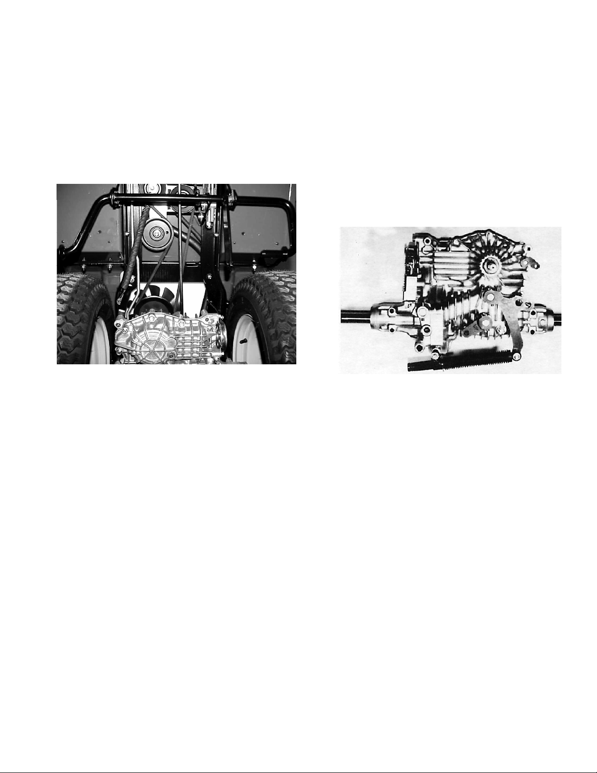
Removing the
Disconnect the brake rod, control rod, tow valve rod, and
reservoir hose from the top of the transaxle.
Transaxle from the
Tractor
Working from the bottom of the tractor, remove the
transaxle drive belt tension spring and drive belt from the
transaxle pulley.
Remove the access panel from the rear of the tractor, to
expose the fuel tank/transaxle.
Support the rear of the tractor with jack stands and
remove the rear wheels.
Remove the two bolts securing the transaxle support rods
to the tractor frame.
Remove the four nuts from the U-bolts which hold the two
axle shafts to the frame.
Remove the transaxle and place it upright on the work
bench.
Remove the fan and spacer from the input pulley (three
cap screws).
Remove the pulley from the shaft (one snap ring).
Figure 1
Figure 2
5Tuff Torq Model K61A Hydrostatic Transaxle Removing the Transaxle from the Tractor
Page 9
Transaxle
Disassembly and
Inspection
Begin disassembly and inspection of the transaxle by
thoroughly cleaning the outside surface of the
transmission.
IMPORTANT: Clean your work area thoroughly and
cover the workbench with clean paper. This is
extremely important as just one grain of sand can
cause a hydrostatic transmission to fail.
Remove the drain bolt from the bottom center and drain
the oil from the transaxle sump.
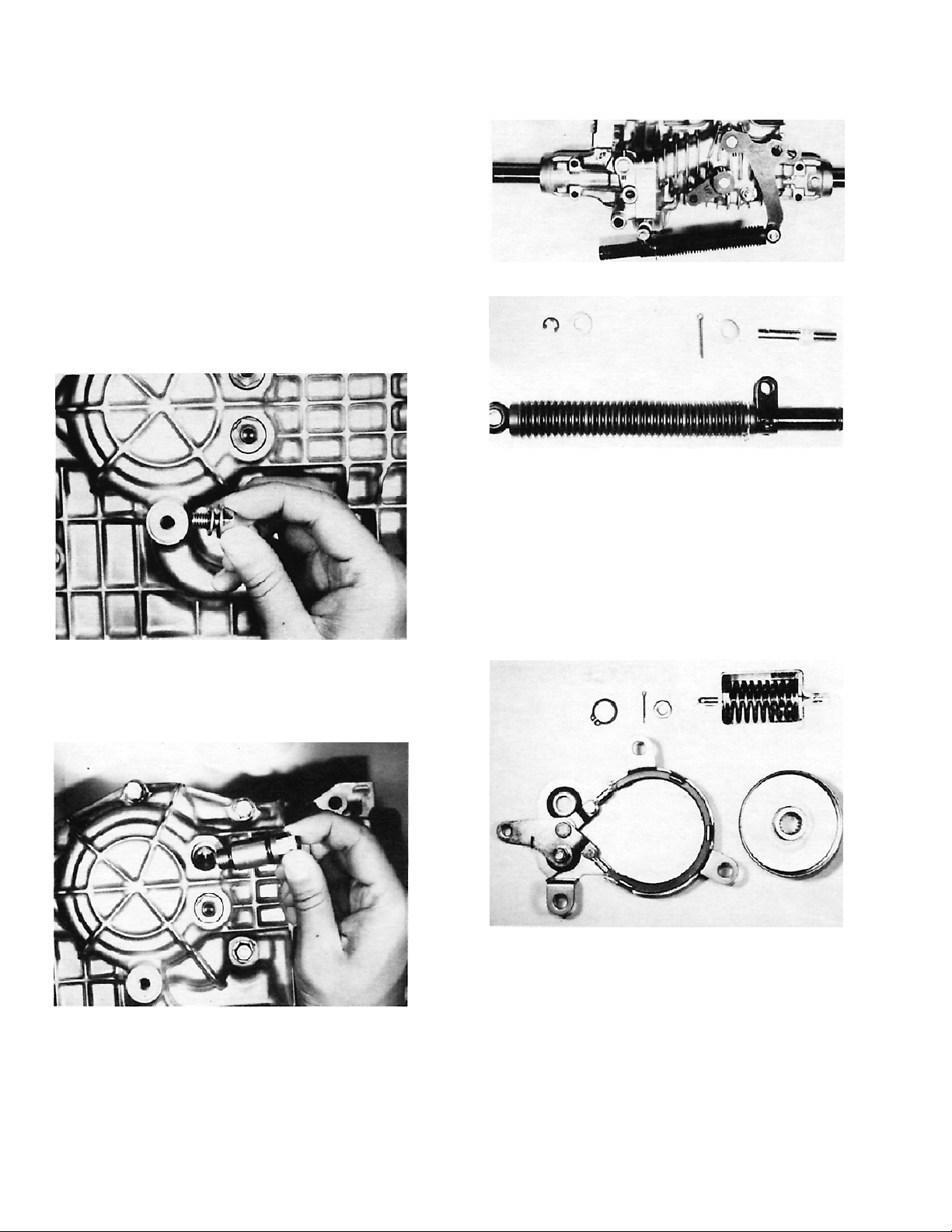
Remove the shock absorber by detaching the E clip,
washer, and cotter pin and its washer. Later models use a
spring clip retainer to secure the shock absorber.
Figure 5
Figure 6
Remove the band brake assembly and brake rod
component by taking out the cotter pin, washer, and three
12mm bolts. Replace the assembly if the friction material
or actuating parts are worn or damaged.
Figure 3
Remove the pressure fill plug and drain the oil from the
rotating groups.
Figure 4
Remove the ring and brake drum.
IMPORTANT: The brake drum and brake band must
be free from oil or dust.
Figure 7
6 Tuff Torq Model K61A Hydrostatic TransaxleTransaxle Disassembly and Inspection
Page 10
Open the transaxle case by taking out the 13 perimeter
12mm bolts and the single center bolt. Pry the bottom
half of the case free from the top half, using care not to
damage the seating surface.
Remove the differential gear assembly.
Figure 11
Figure 8
Lift the pinion shaft assembly from the upper case. There
is a ball bearing on one end of the shaft and a bushing on
the other end.
Figure 9
Remove the collar and ring from the left and right axle
shaft.
Remove the left and right axle shaft and two bushings
from the upper case.
Figure 12
Remove the two seals from the upper case. Remove the
axle bearings if replacing.
Inspect all parts for wear or damage and replace if
necessary.
Figure 10
Figure 13
7Tuff Torq Model K61A Hydrostatic Transaxle Transaxle Disassembly and Inspection
Page 11
Measure the inside diameter of the bushings and the
outside diameter of the left and right axle shaft.
Tab le 1
Measurement Should be:
Disconnect the C arm from the push valve bypass shaft.
Remove the two push pins, springs, and valves from the
center case.
Bushings -
Inside Diameter
Axle Shaft
Outside Diameter
22.06-22.15mm
(.868-.872″)
21.98-22mm
(.865-.866″)
Clearance 0.08-0.17mm
(.003-.006″)
Maximum Wear Limit 0.5mm (.019″)
Measure the inside diameter of the axle bores in the
housing and the outside diameter of the left and right axle
shaft.
Tab le 2
Measurement
Housing Axle Bore --
Inside Diameter
Axle Shaft
Outside Diameter
Should be:
25.44-25.53mm
(1.001-1.005″)
25.32-25.38mm
(.996-.999″)
Clearance 0.06-0.21mm
(.002-.008″)
Figure 15
Remove sleeve A1, sleeve A2, the two backup rings,
packings, balls, ball holders, springs, and bypass holders,
using air pressure if necessary.
Note: Remove the two check valve assemblies only if
necessary (leaking, sticking, or if extra-thorough cleaning
is necessary). Air pressurization will remove one valve;
the other can be pushed out from behind, after the center
section is removed.
1
2
3
Maximum Wear Limit 0.5mm (.019″)
Take the filter out of the center case.
Replace the filter whenever transaxle is
Note:
disassembled for service.
Figure 14
1. Valve A1
2. Valve A2
Figure 16
3. Pressurize with air to
remove valves, if needed
(pressure fill plug shown
installed, with allen head
plug removed).
8 Tuff Torq Model K61A Hydrostatic TransaxleTransaxle Disassembly and Inspection
Page 12
Carefully inspect the packings (o-rings) to ensure they
are not deformed, cut, or scratched. Use new packings
on reassembly.
IMPORTANT: When removing the sleeves, note that
their valves are different, and therefore not
interchangeable. The A1 valve, located farthest from
the axle, has a small hole in it, in addition to the
large hole in the center. For reassembly purposes,
mark the port from which this valve is removed.
1
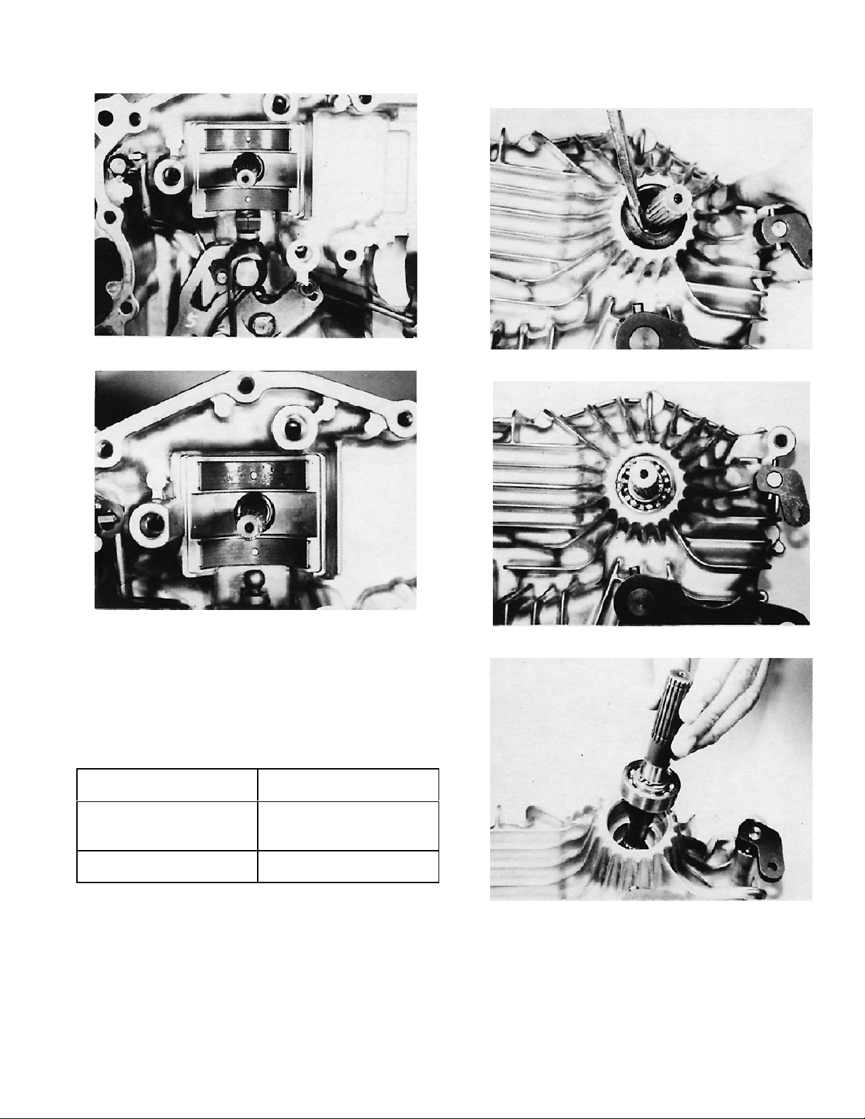
Remove the cylinder block from the pump shaft.
IMPORTANT: Be sure the pistons do not fall out of
the block during removal.
Figure 17
1. Note hole
Loosen the three bolts and remove the magnet from the
center case. Clean the magnet thoroughly; use air
pressure if necessary.
Figure 18
Make a mark on the top of the motor thrust bearing
housing, for easy identification during reassembly.
Remove the motor shaft assembly, along with the center
case assembly, from the upper case.
IMPORTANT: Pay close attention to t he contact
surfaces of the center case and cylinder blocks to
prevent damage.
Figure 20
Inspect the five cylinder bores for burrs or scoring. The
cylinder block and center section must be replaced if any
scratch is deep enough to catch on a fingernail.
Figure 21
Inspect the five pistons and all parts of the cylinder block
assembly for wear or damage.
Replace the center case and both cylinder block
assemblies if any cylinder block assembly parts are
damaged.
Figure 19
Figure 22
9Tuff Torq Model K61A Hydrostatic Transaxle Transaxle Disassembly and Inspection
Page 13
Measure the clearance between the swash plate and shift
blocks.
Replace both shift blocks and the swash plate with new
parts if they are beyond the maximum wear limit.
Tab le 3
Inspect the swash plate, thrust bearing, thrust plates, and
bushing for w ear or damage. Replace with new parts if
necessary.
Measurement
Should be:
Clearance 0.01-0.11mm
(.0003-.004″)
Maximum Wear Limit 0.15mm (.005″)
Remove the spring and ring from the pump s haft.
Figure 25
Figure 23
Remove the swash plate subassembly from the pump
shaft.
Figure 24
Figure 26
Figure 27
10 Tuff Torq Model K61A Hydrostatic TransaxleTransaxle Disassembly and Inspection
Page 14
Remove the shift blocks from the control shaft and
inspect them for wear or damage. Replace if necessary.
Remove the input shaft, seal, and bearing from the upper
case. Remove oil seal and large snap ring from the upper
case. Remove the input shaft and bearing from the case.
Figure 28
Figure 29
Remove the two metal thrust pads from the upper case
and inspect them for wear or damage.
Replace both thrust pads with new parts if the maximum
wear limit is exceeded.
Tab le 4
Figure 30
Figure 31
Measurement
Should be:
Thickness 1.45-1.55mm
(.057-0.61″)
Maximum Wear Limit 1.30mm (.051″)
Figure 32
11Tuff Torq Model K61A Hydrostatic Transaxle Transaxle Disassembly and Inspection
Page 15
Note: If servicing a transaxle with low to moderate use, it
is not necessary to disassemble or remove any of the
levers or linkages from the upper case, unless a part is
damaged or there is an oil leak. If doing a complete
rebuild, all shafts should be removed, inspected, and
packings (o-rings) replaced. If leaving the shafts in place,
avoid excessive use of cleaning solvent on the upper
case half, and do not use solvent that will damage the
packings.
Detach the torsion spring from the control shaft.
Figure 33
Inspect the control shaft, fulcrum, and torsion spring for
wear or damage and replace if necessary.
Figure 36
Inspect the packings (o-rings) to ensure that they are not
cut, scratched, or deformed.
Remove the roll pin and lever from the control shaft
subassembly and the lock nut from the neutral adjusting
fulcrum.
Figure 34
Figure 37
Drive the roll pin from the brake arm secured to the
internal brake shaft.
Remove the brake arm from the brake shaft.
Figure 35
Figure 38
12 Tuff Torq Model K61A Hydrostatic TransaxleTransaxle Disassembly and Inspection
Page 16

Drive the roll pin from the brake arm for the external band
brake.
Remove the brake rod and brake arm from the upper
case.
Inspect the packing for cuts, scratches, or deformation.
Figure 39
Remove the snap pin and washer from the brake rod.
Figure 40
Remove the brake shaft from the upper case.
Inspect the packing (o-ring) for cuts, scratches, or
deformation.
Figure 42
Remove the roll pin from the push valve bypass release
arm.
Disconnect the push valve bypass release arm from the
bypass shaft.
Figure 43
Remove the bypass shaft subassembly, spring, and
bypass rod.
Inspect the packing (o-ring) for cuts, scratches, or
deformation.
Figure 41
Figure 44
13Tuff Torq Model K61A Hydrostatic Transaxle Transaxle Disassembly and Inspection
Page 17

Pinion
Differential Gear
Remove the bearing, bushing, washer, and shaft gear
from the pinion shaft.
Inspect all parts for wear or damage. Replace if
necessary.
Figure 45
Measure the inside diameter of the bushing and the
outside diameter of the pinion shaft.
Tab le 5
Measurement
Bushings --
Inside Diameter
Pinion Shaft --
Outside Diameter
Clearance 0.06-0.16mm
Maximum Wear Limit 0.5mm (.019″)
Should be:
15.05-15.13mm
(.592-.595″)
14.97-14.99mm
(.589-.590″)
(.002-.006″)
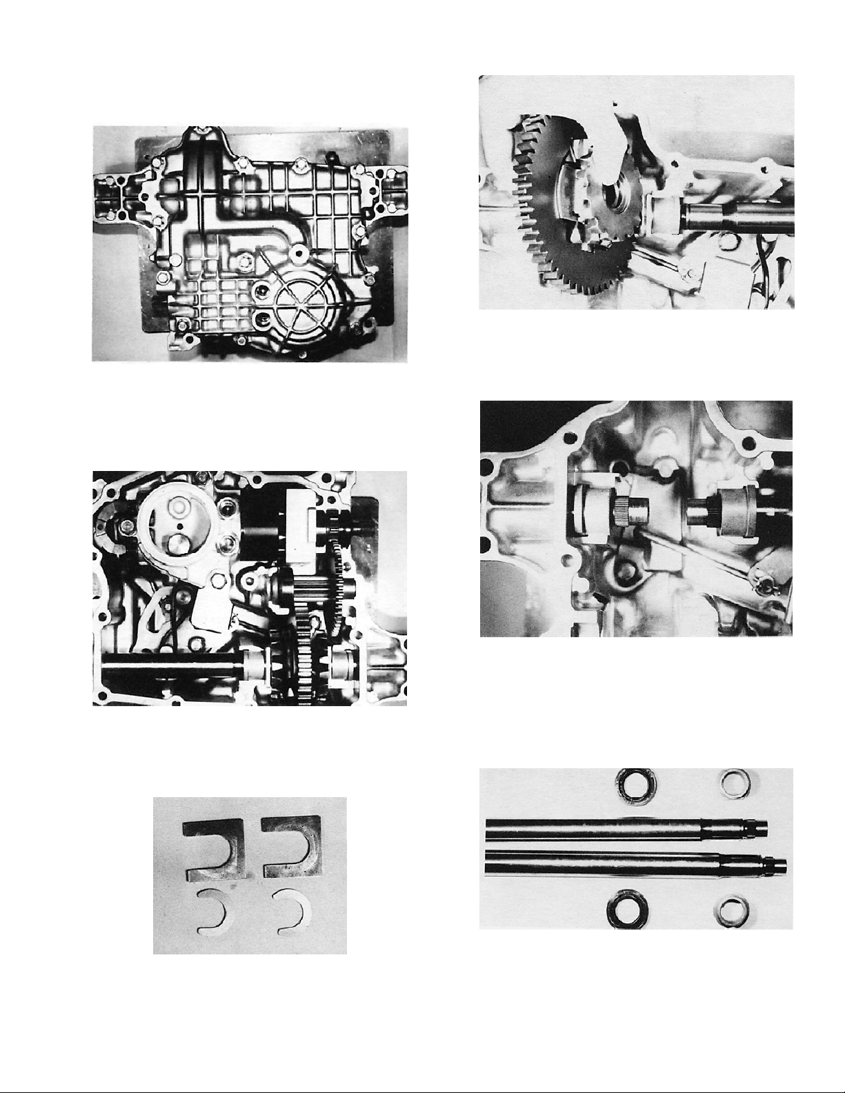
Remove the differential side gears, thrust washers,
differential pinion gears, and differential pinion shaft from
the final gear.
Inspect all parts for wear or damage. Replace if
necessary.
Figure 46
Measure the inside diameter of the differential pinion
gears and the outside diameter of the differential pinion
shaft.
Tab le 6
Measurement
Differential Pinion Gears --
Inside Diameter
Differential Pinion Shaft --
Outside Diameter
Clearance 0.05-0.10mm
Maximum Wear Limit 0.5mm (.019″)
Should be:
15.05-15.06mm
(.592-.593″)
14.96-14.98mm
(.589-.590″)
(.019-.003″)
14 Tuff Torq Model K61A Hydrostatic TransaxleTransaxle Disassembly and Inspection
Page 18

Center Case
Motor Shaft
Take out the two knock pins, plug, and packing (o-ring)
(early models), if required. If the shaft bushings require
replacement, remove them.
Figure 47
Inspect the center case by running your fingernail over its
surface. Replace the center case and cylinder blocks if
fingernail catches on scratches.
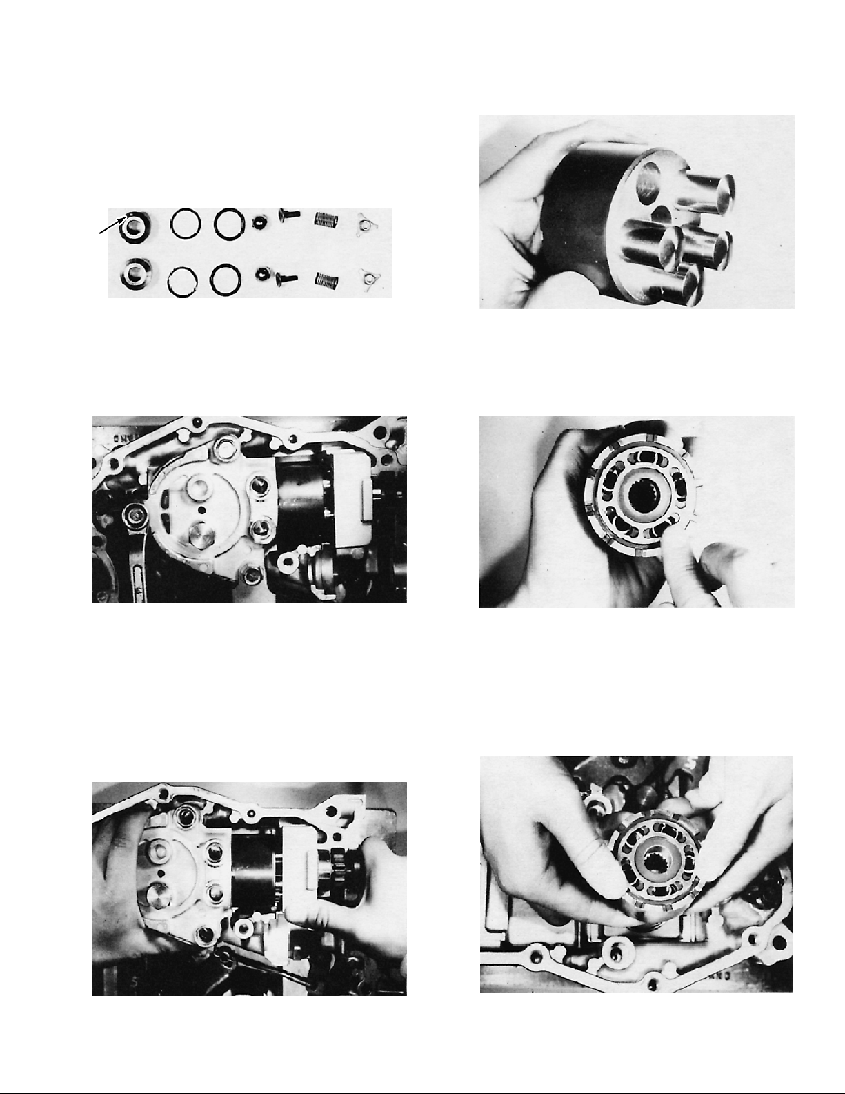
Remove the cylinder block assembly from the motor
shaft.
Inspect the five cylinder bores for burrs or scoring.
Figure 50
Inspect the five pistons and all parts of the cylinder block
assembly for wear or damage.
Replace the center case and both cylinder block
assemblies if any cylinder block assembly parts are
damaged.
Figure 48
Figure 49
Figure 51
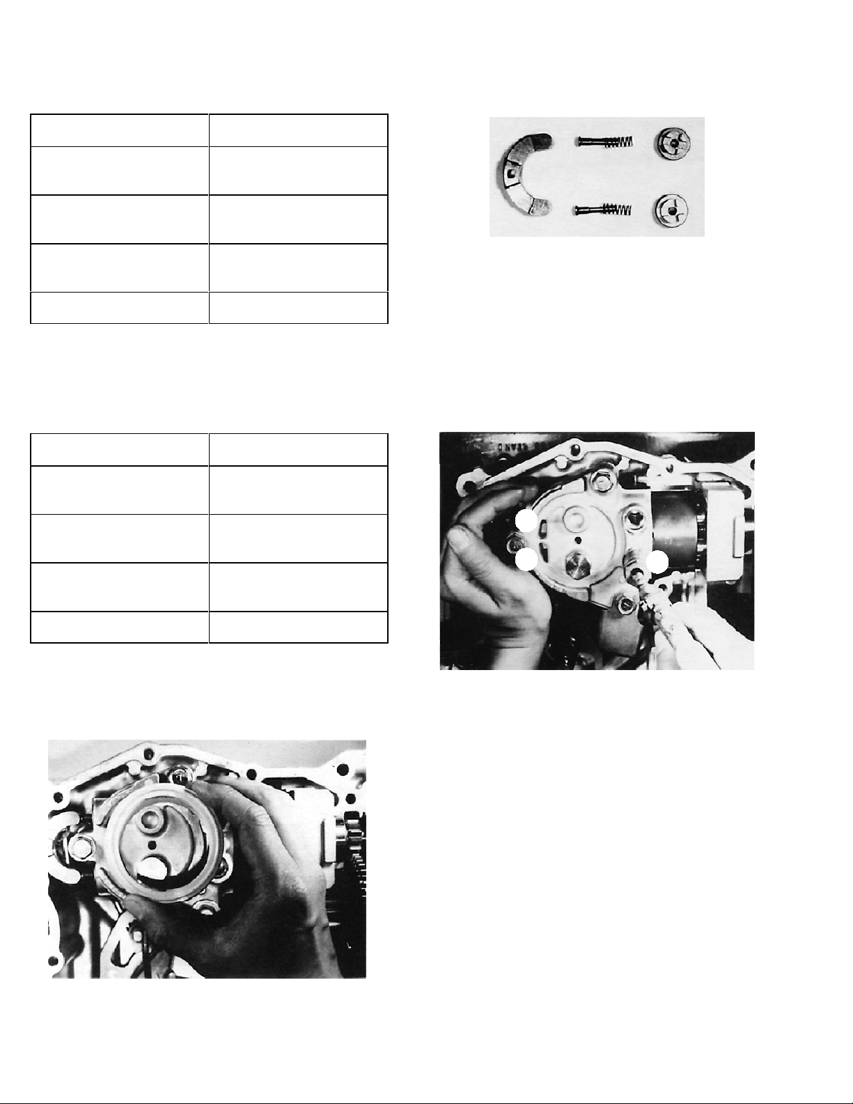
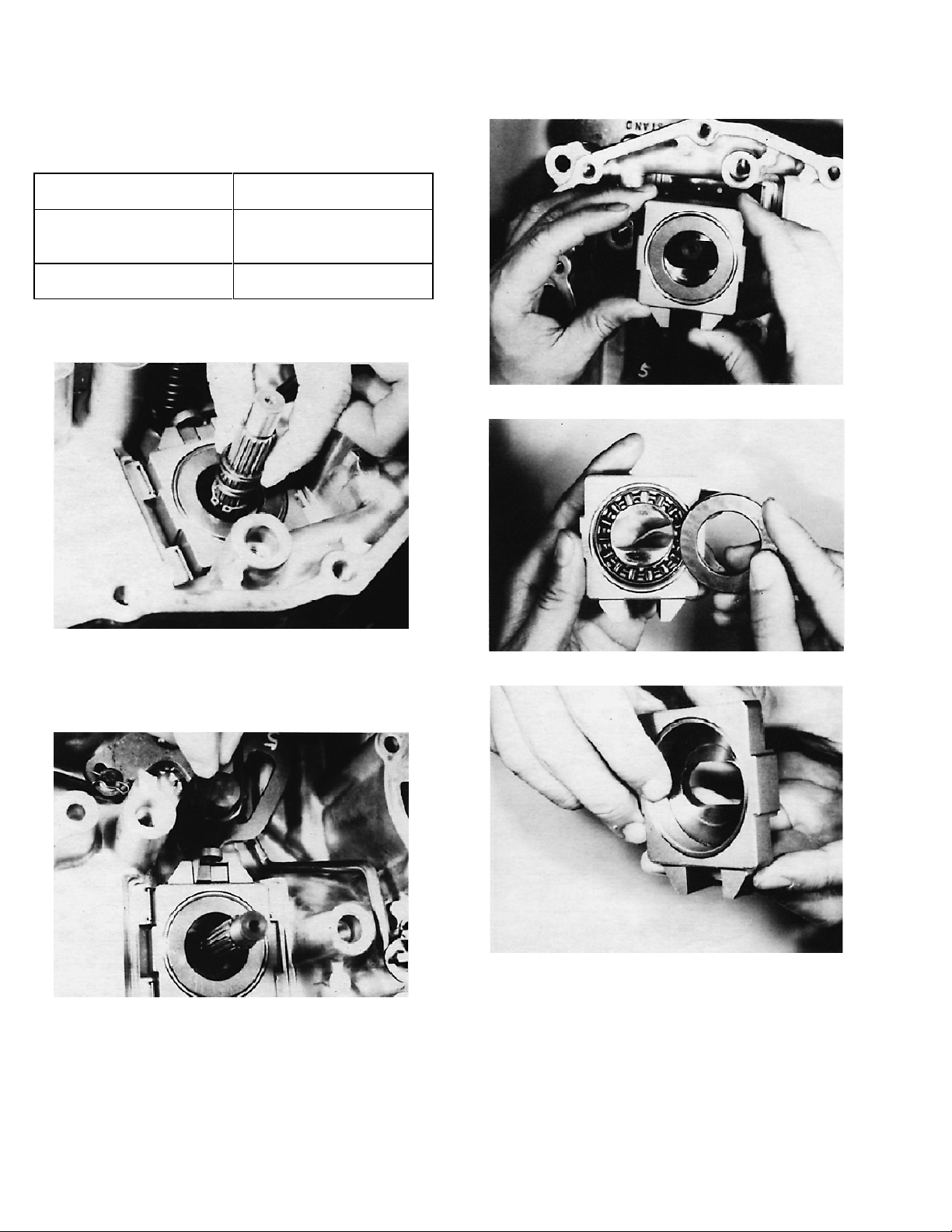
Remove the spring and snap ring from the motor shaft.
Remove the thrust bearing and housing from the motor
shaft and inspect them for wear or damage. Replace if
necessary.
Figure 52
15Tuff Torq Model K61A Hydrostatic Transaxle Transaxle Disassembly and Inspection
Page 19

Remove the snap rings, washer, bearing, and seal from
the motor shaft (brake shaft).
Do not remove the bearing unless it needs to be
Note:
replaced. It is a press fit and will likely be damaged in the
process of removing it.
Figure 53
Pump Shaft
Remove the two snap rings, washer, and bearing from
the pump shaft.
Do not remove the bearing unless it needs to be
Note:
replaced. It is a press fit and will likely be damaged in the
process of removing it.
Inspect the motor shaft and bearing for wear or damage
and replace if necessary.
Figure 54
Figure 55
Inspect the bearing and pump shaft for wear or damage
and replace if necessary.
Figure 56
16 Tuff Torq Model K61A Hydrostatic TransaxleTransaxle Disassembly and Inspection
Page 20

Transaxle Assembly
and Adjustment
IMPORTANT: A clean working environment is
essential during assembly of the transaxle.
Otherwise, your rebuild efforts may not be
successful.
Clean all parts thoroughly prior to assembly. Do not reuse
o-rings or seals; replace with new parts.
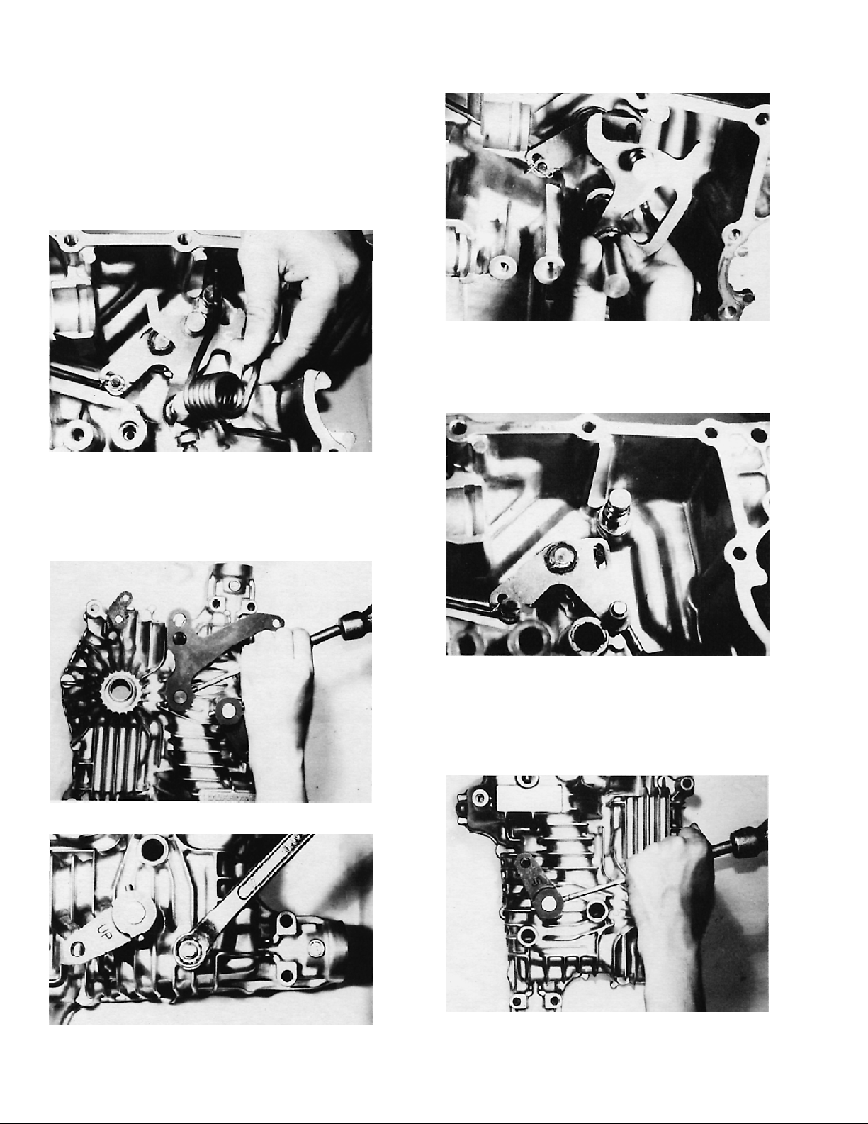
Bypass Return
Place the new packing (o-ring) and spring on the bypass
shaft.
Apply grease to packing before installation.
Note:
Brake Interlock
Place the new packing (o-ring) and brake rod on brake
arm.
Apply grease to packing before installation.
Note:
Apply a light film of grease into the hole of the upper
case, then insert the brake arm into the upper case.
Install the bushing, E-ring, and new packing (o-ring) on
the brake shaft.
Figure 57
Attach the bypass s haft to the upper case.
Figure 58
Place the push valve release arm on the bypass shaft.
Drive the roll pin through the arm and shaft.
Install the bypass rod on the bypass shaft.
Figure 60
Place the spring on the brake shaft.
Figure 61
Apply a light film of grease into the hole in the upper
case, then insert the brake shaft in the upper case, hook
the spring to the housing, and connect the bypass valve
rod to the brake shaft.
Figure 59
Figure 62
17Tuff Torq Model K61A Hydrostatic Transaxle Transaxle Assembly and Adjustment
Page 21

Connect the brake rod to the brake shaft. Place the
washer on the brake rod and then attach the snap pin to
the brake rod.
Figure 63
Install the brake arm on the brake shaft. Make sure the
word “UP” on the brake arm is visible.
Figure 66
Drive the roll pin through the brake arm and brake shaft.
Figure 64
Figure 65
Figure 67
18 Tuff Torq Model K61A Hydrostatic TransaxleTransaxle Assembly and Adjustment
Page 22

Neutral Adjust Eccentric
Place new packing (o-ring) on the neutral adjust
eccentric.
Apply grease to packing before installation.
Note:
Figure 68
Apply a light film of grease into the hole on the upper
case and insert the neutral adjust eccentric into the upper
case.
Install the control shaft in the upper case and position the
torsion spring as shown.
Figure 71
Drive the roll pin through the hydrostatic control arm and
control shaft.
Figure 69
Place new packing (o-ring) and torsion spring on the
control shaft.
Note: Apply grease to packing before installation.
Figure 70
Figure 72
Install the washer and nut on the neutral adjust eccentric.
Figure 73
19Tuff Torq Model K61A Hydrostatic Transaxle Transaxle Assembly and Adjustment
Page 23

Pump Shaft
Install the bearing on the pump shaft.
Install two washers and two snap rings on the pump
shaft.
Make sure the snap rings are seated correctly in
Note:
the pump shaft grooves.
Figure 74
Insert the pump shaft into the upper case.
Install the snap ring and the new seal onto the pump
shaft.
Apply grease to the lip of the seal and place tape
Note:
on the spline of the pump shaft to keep the seal lip from
becoming damaged during installation.
Figure 77
Swash Plate
Insert the two metal thrust pads into the upper case.
Apply oil to the pads.
Figure 75
Figure 76
Figure 78
Apply grease to the inside of the shift blocks to hold them
in place and install the shift blocks on the control shaft.
Figure 79
20 Tuff Torq Model K61A Hydrostatic TransaxleTransaxle Assembly and Adjustment
Page 24

Assemble thin thrust plate, thrust bearing, and thick
thrust plate to the swash plate.
Apply new oil to all parts prior to installation.
Note:
Be sure to place the thinner thrust plate at the
Note:
bottom of the swash plate.
Pump Cylinder Block
Place the snap ring and spring on the pump shaft.
Figure 80
Place the swash plate on the pump shaft. The shift
blocks should be facing toward the slit found on the
swash plate.
Figure 81
Tab le 7
Figure 82
Insert a backup washer and spring into each piston, and
install the pistons in the cylinder block holes.
Note: All parts should be cleaned, and new oil applied to
them, before assembly.
Figure 83
Measurement
Clearance Between Swash
Plate and Shift Blocks
Should be:
0.01--0.11mm
(.0003-.004″)
Figure 84
21Tuff Torq Model K61A Hydrostatic Transaxle Transaxle Assembly and Adjustment
Page 25

Install the cylinder block subassembly on the pump shaft.
Figure 85
Motor Shaft
Install the bearing, washer, and two snap rings on the
motor shaft.
Note: Be sure to place the bearing retainer, which has
the larger inner diameter, at the bottom of the housing.
Figure 89
Assemble the housing to the motor shaft. Install snap ring
and spring on the motor shaft.
Figure 86
Attach the new seal to the motor shaft.
Note: Apply grease to the lip of the seal and place tape
on the spline of the motor shaft to keep the seal lip from
becoming damaged during installation.
Figure 87
Apply new oil to the thrust bearing and install the thrust
bearing on the housing.
Figure 90
Insert a backup washer and spring into each piston, and
install the pistons in the cylinder block.
Note: Clean all parts and apply new oil to them before
assembly.
Assemble the cylinder block to the motor shaft.
Figure 91
Figure 88
22 Tuff Torq Model K61A Hydrostatic TransaxleTransaxle Assembly and Adjustment
Page 26

Center Case
Motor Shaft and Center Case
Install the two knock pins and shaft bushings in the
center case, if removed.
When installing the bushings, make sure they are
Note:
seated correctly in the center case.
Figure 92
Install the two retainers, springs, ball holders, balls, new
packings (o-rings), backup rings, as well as sleeve A1
and sleeve A2 into the center case.
Installation
Oil contact surfaces of center case and cylinder blocks.
Figure 95
Note: Be careful that no damage occurs to the center
case surface during reassembly.
Figure 93
IMPORTANT: Remember, sleeve A1 and sleeve A2
have different valves. The A1 valve has a small hole
in it, in addition to the large hole in the center, and
must be installed in the port located farthest from the
axle.
Note: Apply grease to the packings prior to installation.
To reassemble, place each part in the bore one at a time,
using tweezers or similar tool. Carefully press or tap each
sleeve into its final position.
Check ball movement after assembly.
A1A2
Figure 96
Figure 94
23Tuff Torq Model K61A Hydrostatic Transaxle Transaxle Assembly and Adjustment
Page 27

Install the motor s haft subassembly and center case
subassembly in the case at the same time.
The motor housing is installed so the pistons are
Note:
“in” at the top and “out” at the bottom. Make sure the
pump cylinder block splines are aligned with the pump
shaft. Compress the motor pistons into the cylinder block
while aligning the center case with the mounting holes.
Slowly work the parts into final position, making sure the
pump shaft engages with the cylinder block, the motor
housing and shaft bearing/seal go straight down into their
notches in the upper case, and the motor thrust bearing
stays in the correct position.
Attach the two bypass actuating valves, springs, and
push pins to the center case. Check push pin movement
after assembly.
Figure 99
Note: Assemble and handle components with care so
that no damage occurs to center case surfaces.
Figure 97
Secure the three bolts and magnet to the upper case.
Tighten using a torque of 32 ft. lbs. - 46 ft. lbs. (4.5N
.
m).
6.5N
.
m-
Attach the C arm to the bypass shaft.
Figure 100
Place a new filter on the center case groove.
Figure 98
Figure 101
24 Tuff Torq Model K61A Hydrostatic TransaxleTransaxle Assembly and Adjustment
Page 28

Differential Gear
Axle Shafts and Differential
Attach the two differential pinions to the differential pinion
shaft.
Connect the differential pinion shaft to the final gear.
Place the two thrust washers on the final gear.
Figure 102
Attach the two differential side gears to the final gear.
Installation
Install new seal on the left and right axle shaft.
Figure 104
Apply grease to the lip of each seal before
Note:
installing and use tape on axle to protect seal from
damage during installation.
Figure 103
Figure 105
Install the left and right axle shaft and two bushings in the
upper case.
Figure 106
25Tuff Torq Model K61A Hydrostatic Transaxle Transaxle Assembly and Adjustment
Page 29

Connect the differential gear assembly to the left and
right axle shaft.
Figure 107
Pinion
Secure the bearing to the pinion shaft.
Attach the shaft gear, washer, and bushing to pinion
shaft.
Install a retaining ring on the left and right axle shaft.
Figure 108
Install a collar on the left and right axle shaft.
Figure 110
Install the pinion shaft in the upper case.
Note: Place the bushing on the end of the pinion shaft so
that the flat surface of the bushing collar rests parallel to
the top case surface.
Figure 111
Figure 109
26 Tuff Torq Model K61A Hydrostatic TransaxleTransaxle Assembly and Adjustment
Page 30

Transaxle Case
You can significantly speed up the filling and bleeding
process by adding oil to the upper case half before
installing the lower half. To do this, plug the oil vent hose
fitting. Secure the case so it does not move, and then fill
it to half full with oil.
Thoroughly clean the mating surface of each case half.
Apply a thin, even bead of Loctite 587 or Permatex Ultra
Blue RTV sealant to the upper case mating surface.
IMPORTANT: Do not turn the transaxle over until the
sealant has had time to set up.
Join the lower case to the upper case.
Torque Sequence
1 280 in. lbs. (31.6N·m)
2 280 in. lbs. (31.6N·m)
3 280 in. lbs. (31.6N·m)
4 280 in. lbs. (31.6N·m)
5 280 in. lbs. (31.6N·m)
6 280 in. lbs. (31.6N·m)
7 280 in. lbs. (31.6N·m)
8 280 in. lbs. (31.6N·m)
9 280 in. lbs. (31.6N·m)
10 280 in. lbs. (31.6N·m)
11 280 in. lbs. (31.6N·m)
12 300 in. lbs. (33.9N·m)
13 300 in. lbs. (33.9N·m)
Torque Value
Figure 112
Note: Apply sealant to the inside surface around the bolt
holes, and to the surface of the inner boss for the single
center bolt.
Figure 113
Figure 114
Figure 115
27Tuff Torq Model K61A Hydrostatic Transaxle Transaxle Assembly and Adjustment
Page 31

Install new packings (o-rings) on the pressure fill
connector.
Attach the connector to the center case through the lower
case. (Install finger tight if planning to bleed air from
transaxle before installing in tractor.)
Note: For quick air bleeding, apply new oil into the
connector hole of the center case while rotating the pump
and motor shaft by hand. See
Circuit
completely filling transaxle with oil.
. Be sure sealant has had time to set up before
Bleeding Air from the Oil
Brake
Secure the brake drum to the motor shaft with retaining
ring.
IMPORTANT: The brake drum must be free from oil or
dust.
Figure 118
Figure 116
Secure the drain bolt to the lower case using a new seal
washer. Tighten using a torque of 9 ft. lbs. - 12 ft. lbs.
.
m - 1.7N.m).
(1.3N
Figure 117
Attach the band brake using the three bolts. Secure the
bolts while pushing the band brake assembly toward the
lower case side. Tighten using a torque of 16 ft. lbs. - 21
ft. lbs. (2.3N·m - 3.0N·m).
Figure 119
28 Tuff Torq Model K61A Hydrostatic TransaxleTransaxle Assembly and Adjustment
Page 32

Attach the brake rod to brake arm. When inserting the
rod (adjuster) into the hole on the brake cam lever, adjust
the length of the rod to fit the brake arm hole.
Put the brake rod component onto the band brake and
install the washer and cotter pin on the brake rod.
Figure 120
Note: Alternate oil—a synthetic oil (5W--50 or similar
viscosity range) may be used in place of SAE 10W--30.
This oil will permit an increase in the maximum operating
temperature of approximately 18_F(10_C).
Install the transaxle in the tractor.
Top off the reservoir with oil through the reservoir/fill cap,
filling it to the cold fill mark.
Test operate the transaxle as described in the following
section, and make sure transaxle is filled to the correct oil
level.
Damper
Attach stud to the upper transaxle case.
Install the shock absorber, washer, and cotter pin on the
stud. (Later production is secured with spring clips.)
Install the washer and ring.
Figure 121
Bleeding Air from the Oil Circuit
Unit Out of Tractor
You can bleed the transaxle oil circuit free of air before
installing it in the tractor.
Plug the reservoir/fill hose port on top of the transaxle.
Position the transaxle with the bottom side facing up.
Rotate the input shaft by hand while adding
approximately 2 quarts (1.9 liters) of SAE 10W-30 API
Service Classification SH or higher oil through the
transaxle pressure fill port.
Figure 122
Unit in Tractor
Bleed the oil circuit so that it is free of air whenever you
install a new or rebuilt transaxle in the tractor.
Add SAE 10W-30 API Service C lassification SH or higher
oil to the transaxle through the reservoir fill cap. Fill to the
reservoir’s cold fill mark. Attempt to get as much air as
possible out of the hose before starting the bleeding
process.
Alternate oil—a synthetic oil (5W--50 or similar
Note:
viscosity range) may be used in place of SAE 10W--30.
This oil will permit an increase in the maximum operating
temperature of approximately 18_F(10_C).
Raise the two rear tires from the ground and support the
tractor securely with jack stands.
Disconnect the seat switch and attach a jumper wire
across the terminals so that the tractor will run without an
operator in the seat.
Start the engine and maintain low idle speed.
Depress the forward and reverse hydrostatic control
pedals alternately until the wheels begin to rotate. Shut
engine off.
Lower the tractor to the ground.
29Tuff Torq Model K61A Hydrostatic Transaxle Transaxle Assembly and Adjustment
Page 33

Use extreme caution while completing the
following bleeding process.
Restart the engine and set at low idle speed.
Depress the forward hydrostatic control pedal and push
the tractor rearward. Then depress the reverse
hydrostatic control pedal and push the tractor forward
until the tractor is able to move under its own power.
Loosen the locknut, B, and turn the eccentric, A,
counterclockwise until the wheels start to rotate
forward, C.
Turn the eccentric clockwise until the wheels begin to
rotate in reverse, D.
Move the eccentric to the center of the neutral band, E,
and tighten the locknut.
Increase engine speed to full RPM.
Operate the tractor, making quick starts and panic stops,
until the transaxle is operating properly. Top forward
speed is 5 MPH--5.5 MPH (8km/hr--8.8km/hr).
Top off the reservoir with oil through the reservoir/fill cap,
filling it to the cold fill mark.
Note: Transaxle oil capacity is 3.5 qts. (3.3 liters).
Transaxle Neutral Adjustment
You must perform a neutral adjustment whenever a
tractor creeps in neutral, or whenever a new or rebuilt
transaxle is installed in the tractor.
Remove the access panel at the rear of the tractor to
gain access to the neutral adjusting eccentric, which is
located on the top right-hand side next to the gas damper
arm. (Fig. 123 shows wrench applied to eccentric—seat,
fender, and fuel tank are removed in photo for clarity.)
Raise the rear wheels off the ground and support the
tractor securely on jack stands.
Disconnect the seat switch and attach a jumper wire
across the terminals. This enables the tractor to run
without an operator in the seat.
Check the neutral adjustment by depressing the motion
control pedal in forward and reverse. At full throttle, there
should be no wheel movement after the pedal returns to
neutral. Readjust as needed until neutral is obtained.
Figure 124
Set engine speed at full throttle.
Figure 123
30 Tuff Torq Model K61A Hydrostatic TransaxleTransaxle Assembly and Adjustment
Page 34

Belts and Linkage
Belt Replacement
Note: Perform V-belt installation, routing, and inspection
procedures from beneath the tractor.
Take out the four screws holding the tunnel cover in
place. Remove the cover.
Detach the belt tension spring, A.
Disconnect the electric clutch wire.
Remove the two steering link rods from the sector gear.
Disconnect the brake rod from the transaxle.
Detach the hydrostatic control rod from the hydrostatic
pedal lever, B.
Disconnect the brake pedal safety start switch wires and
remove the bracket to which the switch(es) is/are
mounted.
Loosen the rear bolt and remove the front bolt retaining
the right-hand footrest to the frame (provides brake shaft
clearance).
Remove the hydrostatic cross shaft support brackets
from both footrests, C.
Remove the far right pin only
(the pin closest to the
hydrostatic pedal), D, from the hydrostatic cross shaft.
(Later models do not have pins.)
Note: There are three pins in the hydrostatic cross shaft.
Do not remove the other two pins.
Slide the hydrostatic cross shaft, E, to the left and
remove the hydrostatic pedal assembly, F.
Remove the roll pin from the left end of the brake cross
shaft, G.
Move the brake cross shaft to the right and route the
V-belt out of the tractor.
Figure 125 -- Bottom View
A. Belt tension spring
B. Hydrostatic control rod
C. Hydrostatic cross shaft
support bracket
D. Hydrostatic cross shaft
pin
E. Hydrostatic cross shaft
F. Hydrostatic pedal
assembly
G. Brake cross shaft
31Tuff Torq Model K61A Hydrostatic Transaxle Belts and Linkage
Page 35

Belt Routing—Bottom View
The drive belt contacts a single V-idler pulley on the left
side as it is routed from the engine pulley to the transaxle
pulley.
As it travels back from the transaxle pulley to the engine
pulley, it passes between a pair of idler pulleys (a flat idler
pulley and a V-idler pulley).
All three idler pulleys are mounted to the idler arm. Two
pulleys are spring loaded; one is held in place with an
eccentric.
Figure 126
Reassembly
After routing the V-belt, reconnect the following parts:
• Belt tension spring
• Electric clutch wire
• Two steering link rods at the sector gear
• Brake rod at the transaxle
• Hydrostatic control rod at the hydrostatic pedal lever
• Brake pedal
safety start switch
• Hydrostatic cross shaft support bracket at each
footrest
• Far right pin in the hydrostatic cross shaft (N/A, newer
models)
• Hydrostatic pedal assembly
• Roll pin in left end of the brake cross shaft
Finally, secure the tunnel cover in place.
32 Tuff Torq Model K61A Hydrostatic TransaxleBelts and Linkage
Page 36

Belt Adjustment
Remove the tunnel cover to check or adjust belt tension.
Loosen the back side idler pulley, A, and move it in the
slotted mounting hole on the idler arm, B.
For additional adjustment, turn the eccentric, C, on the
eccentric mounted idler pulley, D.
Figure 127
A. Back side idler pulley
B. Idler arm
C. Eccentric
D. Eccentric mounted idler
pulley
33Tuff Torq Model K61A Hydrostatic Transaxle Belts and Linkage
Page 37

A. Fan
B. Fan spacer
C. Snap ring
Figure 128
D. Pulley
E. Setscrew 1/4″--2 0 x 1 / 4
″
34 Tuff Torq Model K61A Hydrostatic TransaxleBelts and Linkage
Page 38

Brake Linkage
Foot Brake
Description and Operation
The foot and parking brake linkage consists of the
following main components:
• Brake pedal
• Brake lever
• Brake rod
• Return spring
• Trunnion
• Parking brake lever
When the brake pedal, A, is depressed, the brake lever,
B, (located on the other end of the brake pedal shaft)
rotates. This activates the brake rod, C, and return
spring, D, which are both connected to the brake lever.
The other end of the return spring is fastened to a
bracket located below the eccentric-mounted idler pulley.
The action is then transferred to the trunnion, F, which
connects the threaded brake rod to the control lever, E,
on the transaxle, stopping the tractor.
Adjustment
Move the control lever, E, to its most rearward position
and hold it there.
Adjust the trunnion, F, on the brake rod, C, until it slips
into the control lever, E.
Parking Brake
Description and Operation
When the brake pedal, A, is depressed and the parking
brake lever, G, is lifted, the end of the parking brake lever
lowers into position behind the brake lever, B. This
prevents the return spring, D, from disengaging the brake
when the brake pedal is released.
A. Brake pedal
B. Brake lever
C. Brake rod
D. Return spring
Figure 129
E. Control lever
F. Trunnion
G. Parking brake lever
35Tuff Torq Model K61A Hydrostatic Transaxle Belts and Linkage
Page 39

Transaxle Brake
Description and Operation
Fig. 130 illustrates the main components of the transaxle
brake.
When the brake pedal is depressed, internal linkage pulls
the brake control arm, A, forward and rotates the brake
lever, B. This movement is then transferred to the brake
rod, C, which rotates the brake shaft, D. The brake shaft
projects through the top of the case and is attached to
the brake arm, E.
When the brake arm rotates, it activates the brake spring
assembly, F. The brake link assembly then allows only so
much force to be applied to the brake band, G, for
braking action. Because the brake band encircles the
B
J
K
A
C
brake drum, H, and the brake drum is splined to the
hydrostatic motor output shaft, the tractor comes to a
stop.
At the same time, the lobe, I, located on the brake lever
acts upon the cam slot, J, profile of the swash plate
control cam, K. This locks the hydrostatic control linkage
in place (neutral position).
When the hydrostatic push valve is activated via a
hand-operated rod at the rear of the tractor, the rod, L,
connected to the brake lever is pulled to the end of the
slot in the brake lever, B. When the brake is next applied,
this rod rotates the push valve shaft, M, and actuator, N,
and deactivates the push valve plungers, O.
E
D
A. Brake control arm
B. Brake lever
C. Brake rod
D. Brake shaft
G
H
E. Brake arm
F. Brake spring assembly
G. Brake band
H. Brake drum
F
I
M
Figure 130
I. Brake lever lobe
J. Swash plate control cam slot
K. Swash plate control cam
L. Push valve rod
L
N
A
B
O
M. Push valve shaft
N. Actuator
O. Push valve plunger
36 Tuff Torq Model K61A Hydrostatic TransaxleBelts and Linkage
Page 40

Brake Band Adjustment
Loosen the rod, A, from the brake band assembly, B.
Move the brake lever, C, to its most rearward position
and hold it there.
Adjust the rod, A, until it slips easily into the hole in the
brake band assembly actuator arm, D.
Figure 131
A. Rod
B. Brake band assembly
C. Brake lever
D. Brake band assembly
actuator arm
37Tuff Torq Model K61A Hydrostatic Transaxle Belts and Linkage
Page 41

Hydrostatic Control Linkage
Pedal Adjustment
Description and Operation
The hydrostatic control pedal assembly has a forward
and reverse pad and is fitted to the cross shaft, C, for
rotation. One end of the control rod, D, is attached to the
pedal assembly; the other end is attached to the
transaxle control arm, E. The ends of the control rod are
threaded.
When the pedal is depressed, the control rod moves the
transaxle control arm. When the pedal is released, the
transaxle control arm’s internal spring deactivates the
control rod, returning the transaxle to the neutral position.
Lubrication
Grease the hydrostatic control pedal after every 50 hours
of operation.
Remove the rear fender and seat assembly.
Take out the two fuel tank mounting bolts. Remove the
tank and set it to the left side of the tractor.
Loosen the jam nut and remove the bolt from the rear rod
end of the control rod, F (where it fastens to the transaxle
control arm, E).
Adjust the rear rod end, F, of the control rod, D, so that
the rear edge of the control pedal reverse pad, B, is 1.25″
(32mm) from the footrest.
A. Forward
pedal pad
B. Reverse
pedal pad
Figure 132
C. Cross shaft
D. Control rod
E. Control arm
F. Rod ends
38 Tuff Torq Model K61A Hydrostatic TransaxleBelts and Linkage
Page 42

Cruise Control
Description and Operation
The hydrostatic transaxle can be held at a desired speed
with cruise control, standard equipment on some models.
Its effect on the transmission system is described below.
For electrical troubleshooting, refer to the Toro Riding
Products Demystification Guide, form 492--4509.
The cruise control is activated by a three-position rocker
switch located on the right-hand side of the dash panel.
Cruise can b e set with the ignition switch in the LIGHTS
or RUN position. A green light on the rocker switch
illuminates to indicate that the cruise control is ON.
After starting the tractor and reaching the desired
operating speed, engage the cruise control by placing the
control switch in the SET position. This activates the
electromagnet which holds the hydrostatic pedal in place.
The cruise can be disengaged by depressing the brake
pedal or by placing the rocker switch in the OFF position.
Electrical current to the magnet is interrupted, and the
hydrostatic pedal returns to neutral.
Components
1. Rocker switch and
housing
2. Plate-hydrostatic control
arm and bracket
3. Bracket magnet
Figure 133
4. Magnet
5. Brake switch and
mounting bracket
6. Replay
7. Wire harness
Cruise control will function with the hydrostatic pedal in
either the forward or reverse position.
The tractor cannot be started w ith the cruise control
engaged. To start the tractor, the brake pedal must be
depressed, and this disengages the cruise feature.
Figure 132
Plate-Hydrostatic Control Arm and Housing
The plate is mounted to the hydrostatic control arm by a
bracket. Because of the plate’s thickness, a longer bolt is
needed to fasten the hydrostatic linkage to the control
arm.
The magnet’s electrical leads are routed along and tied to
the hydrostatic reservoir hose. These leads must not
come in contact with any moving parts, i.e., the fan, belts,
pulleys, linkage, etc.
Figure 134
39Tuff Torq Model K61A Hydrostatic Transaxle Belts and Linkage
Page 43

Bracket Magnet
Relay
The bracket which holds the magnet is secured to the
frame by two bolts and locknuts.
Magnet
The magnet is located on the spring post of the bracket.
It is correctly seated when the tab is inserted through the
bracket slot.
Figure 135
A fourth relay is added to the relay panel when cruise
control is installed. The relay receptacle on the cruise
wire harness attaches to the existing receptacle on the
relay panel.
Figure 137
Brake Switch and Mounting Bracket
A second brake switch is used with cruise control. It is
mounted back to back with the brake safety start switch.
The bracket has a slotted hole, allowing for adjustment of
the switches. The cruise brake switch should be adjusted
to disengage when the brake pedal is slightly depressed.
Figure 136 -- Bottom View
40 Tuff Torq Model K61A Hydrostatic TransaxleBelts and Linkage
Page 44

Troubleshooting
Problem Possible Cause
No drive Incorrect oil/oil level in unit
Drive belt has failed, is worn, or tension is out of adjustment
Push valve in push position
Parking brake engaged
Control pedal linkage
Engine pulley or transmission pulley
Hydrostatic filter plugged
Push valve plunger, springs, or valve body
Directional valves stuck or spring broken
Damage to rotating groups or valve body
Damaged pinion shaft or differential assembly
No drive—one direction Control pedal bent or broken
Control pedal rod bent or binding
Control arm roll pin sheared
Directional valves sticking, broken springs, or need to be cleaned of debris
Low power—both directions Incorrect oil/oil level in unit
Drive belt has failed, is worn, is out of position, at incorrect tension, or engine
RPM
Push valve partially activated
Parking brake engaged or binding
Control pedal or linkage binding
Engine or transaxle drive pulleys loose, damaged, worn
Hydrostatic filter plugged
Directional valves sticking, need to be cleaned of debris, broken springs
Damage to rotating groups or valve body
Swash plate worn, damaged, not operating properly
Damaged output pinion or differential assembly
Low power—one direction Incorrect oil/oil level in unit
Control pedal or shaft bent, binding, or travel
Control rod bent or binding
Control arm is not secure on shaft
Clogged oil filter
Swash plate worn, damaged, or not operating properly
Check directional valve plungers for binding, broken spring, debris, or leakage
Differential assembly binding or damaged
41Tuff Torq Model K61A Hydrostatic Transaxle Troubleshooting
Page 45

Problem Possible Cause
Creeps in neutral Neutral adjustment eccentric out of position
Control pedal bent or binding
Control rod bent or binding
Swash plate control lever pin damaged, bent, binding, or worn
Swash plate cradle bearings failed, worn, or damaged
Swash plate control arm ball and socket damaged or worn
Neutral return spring failed, fatigued, or out of position
42 Tuff Torq Model K61A Hydrostatic TransaxleTroubleshooting
Page 46

Page 47

 Loading...