

Toro 136-7494 Installation Instructions

ThisproductcontainsachemicalorchemicalsknowntotheStateofCalifornia
Installation
PreparingtheMachine
BucketMountKit
TimeCutter
ModelNo.136-7494
tocausecancer,birthdefects,orreproductiveharm.
®
HDRidingMower
Proposition65Warning
WARNING
CALIFORNIA
FormNo.3415-421RevA
InstallationInstructions
1.Parkthemachineonalevelsurface.
2.Disengagetheblade-controlswitch.
3.Engagetheparkingbrake.
4.Movethemotion-controlleversoutwardtothe
NEUTRAL-LOCKposition.
5.Shutofftheengineandremovethekey.
©2017—TheT oro®Company
8111LyndaleAvenueSouth
Bloomington,MN55420
Registeratwww.T oro.com.
OriginalInstructions(EN)
PrintedintheUSA
AllRightsReserved
*3415-421*A
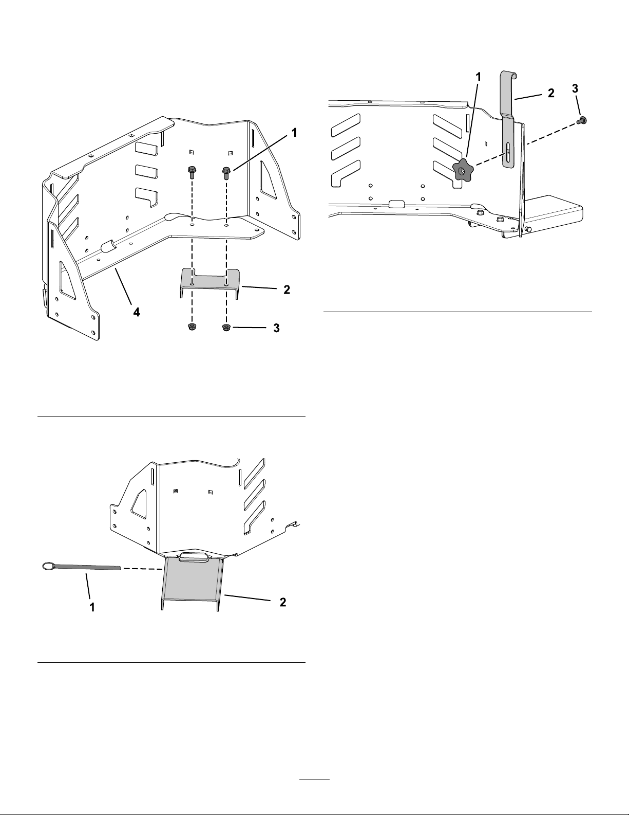
InstallingtheBucketMount
Kit
1.Securethebrackettotheengineguardusing2
ange-headbolts(5/16x3/4inch)and2ange
nuts(5/16inch)asshowninFigure1.
3.Securethebucketretainertotheengineguard
usingthecarriagebolt(5/16x7/8inch)and
handleknob(Figure3).
g209905
Figure3
Figure1
1.Flange-headbolt(5/16x
3/4inch)
2.Bracket4.Engineguard
3.Flangenut(5/16inch)
2.Securetheplatetothebracketusingthelocking
pin(Figure2).
1.Handleknob
2.Bucketretainer
g212124
3.Carriagebolt(5/16x7/8
inch)
Figure2
1.Lockingpin2.Plate
g212122
2
 Loading...