

Page 1
FormNo.3422-238RevA
BeltKit
SGR-6StumpGrinder
ModelNo.138-3121
ModelNo.138-3125
InstallationInstructions
Safety
WARNING
CALIFORNIA
Proposition65Warning
ThisproductcontainsachemicalorchemicalsknowntotheStateofCalifornia
tocausecancer,birthdefects,orreproductiveharm.
SafetyandInstructionalDecals
Safetydecalsandinstructionsareeasilyvisibletotheoperatorandarelocatednearanyarea
ofpotentialdanger.Replaceanydecalthatisdamagedormissing.
117-4979
1.Rotatingbelt—keepguardinplace.
decal117-4979
decal119-4692
119-4692
1.Warning—shutofftheengine;usebothhandholdstolift
thegrinder.
©2018—TheT oro®Company
8111LyndaleAvenueSouth
Bloomington,MN55420
Registeratwww.T oro.com.
OriginalInstructions(EN)
PrintedintheUSA
AllRightsReserved
*3422-238*A
Page 2
Installation
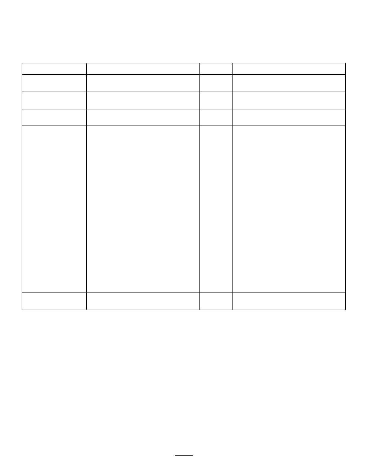
LooseParts
Usethechartbelowtoverifythatallpartshavebeenshipped.
ProcedureDescription
1
2
3
4
Nopartsrequired
Nopartsrequired
WheelT oothKit1
Cutterwheel
Bearingassembly2
Bolt(3/8x1-1/2inches)
Washer(0.40x0.81x0.11inches)
Locknut(3/8inch)
Guardplate
Flangebolt(5/16x3/4inch)
Carriagebolt(5/16x3/4inch)
Locknut(5/16inch)
Frontpulley1
Squarekey
Washer(0.27x0.89x0.09inches)
Bolt(1/4x3/4inch)
Clutchpulley
Washer(0.76x1.26x0.07inches)
Washer(0.32x1.12x0.18inches)
Washer(0.31x0.78x0.07inches)
Bolt(5/16x1-1/8inch)
Belt1
Beltguard1
Bolt(3/8x1inch)
Washer(0.38x0.75x0.08inches)
Qty.
Use
–
–
1
4
8
4
1
2
1
3
1
1
1
1
2
1
1
1
2
2
Preparethemachine.
Removetheexistingbeltandcutter
wheel.
Installthewheelteeth.
Installthecutterwheelandbelt.
5
Decal1
2
Installthedecal(Model138-3125only).
Page 3
1
PreparingtheMachine
NoPartsRequired
Procedure
1.Parkthemachineonalevelsurface.
2.Engagetheparkingbrake.
3.Shutofftheengine.
4.Disconnectthesparkplugwirefromthespark
plug.
2
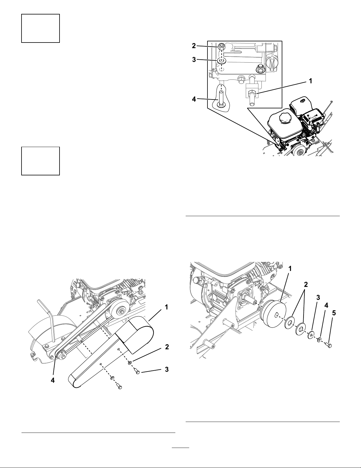
2.Loosen,orremoveandretain,the4carriage
bolts,4washers,and4locknutssecuringthe
enginetotheframe(Figure2).
g238897
Figure2
Frontfastenersshown
RemovingtheExistingBelt andCutterWheel
NoPartsRequired
Procedure
Note:Discardallremovedpartsunlessindicated
otherwise.
1.Removethe2bolts,2washers,andbeltguard
(Figure1).
1.Jamnut3.Washer—0.38x0.73x
0.07inches(4)
2.Locknut—5/16inch(4)4.Carriagebolt—5/16x
1-1/2inches(4)
3.Loosenthejamnutonthetensionerbolt(Figure
2).
4.Removethebelt(Figure1).
5.Removetheclutchpulley(Figure3).
1.Beltguard
2.Washer—0.38x0.75x
0.08inches(2)
Figure1
3.Bolt—3/8x1inch(2)
4.Belt
g238742
Figure3
1.Clutchpulley4.Washer(0.31x0.75x0.08
g238745
2.Washer(0.81x2.00x0.15
inches)
3.Washer(0.39x1.25x0.12
inches)
3
inches)
5.Bolt(5/16x3/4inch)
Page 4
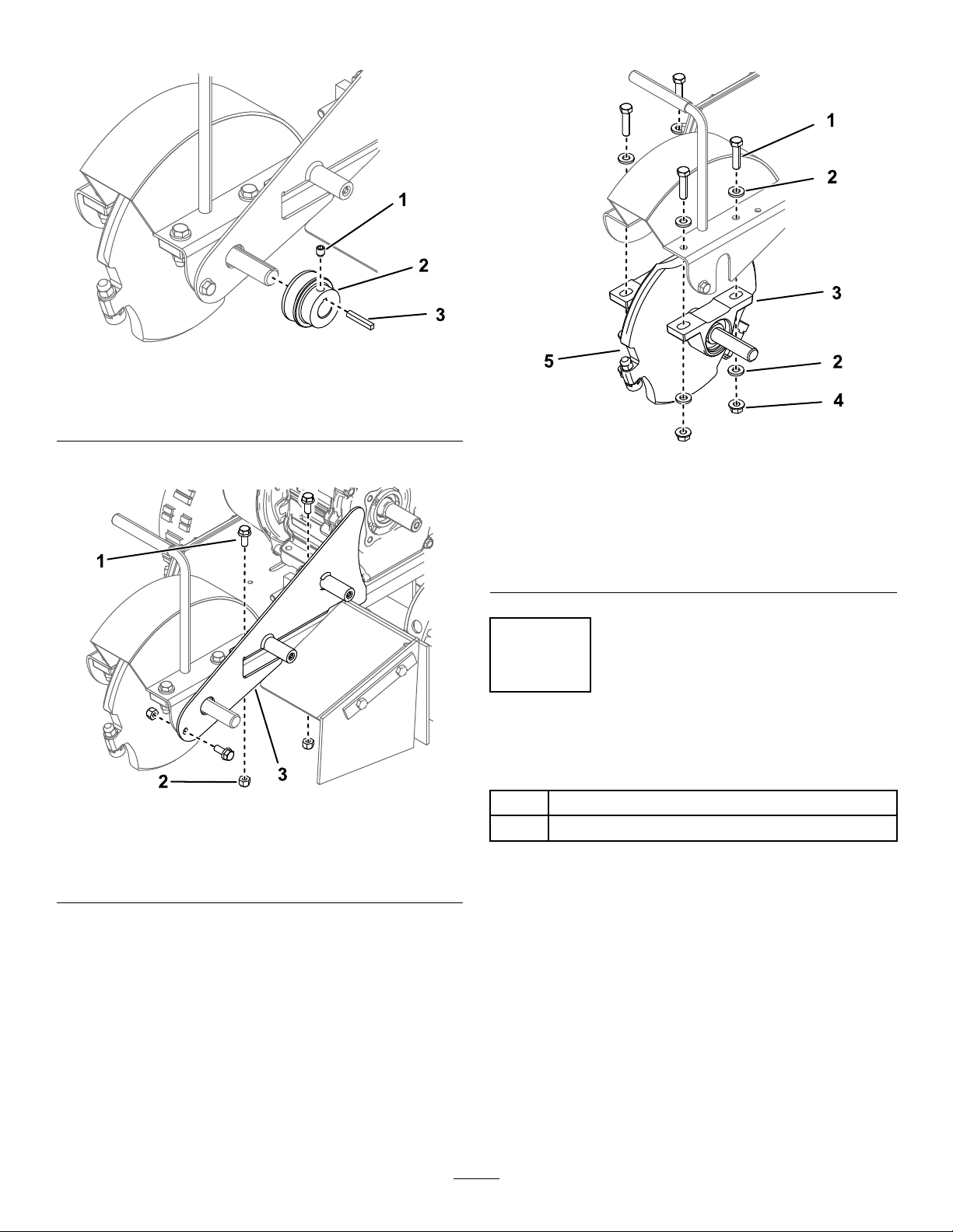
6.Removethefrontpulley(Figure4).
Figure4
1.Setscrew3.Squarekey
2.Frontpulley
7.Removetheguardplate(Figure5).
8.Removethecutterwheel(Figure6).
g238744
g238743
Figure6
1.Flangebolt—5/16x3/4
inch(3)
2.Locknut—5/16inch(3)
Figure5
3.Guardplate
1.Bolt—3/8x1-1/2inches
(4)
2.Washer—0.40x0.81x
0.11inches(8)
3.Bearingassembly(2)
4.Locknut—3/8inch(4)
5.Cutterwheel
3
InstallingtheWheelTeeth
Partsneededforthisprocedure:
g238746
1WheelT oothKit
1
Cutterwheel
Procedure
RefertotheInstallationInstructionsforthekittoinstall
thewheelteethtothecutterwheel.
4
Page 5
4
InstallingtheCutterWheel
andBelt
Partsneededforthisprocedure:
2Bearingassembly
4
Bolt(3/8x1-1/2inches)
8
Washer(0.40x0.81x0.1 1inches)
4
Locknut(3/8inch)
1
Guardplate
2
Flangebolt(5/16x3/4inch)
1
Carriagebolt(5/16x3/4inch)
3
Locknut(5/16inch)
1Frontpulley
1
Squarekey
1
Washer(0.27x0.89x0.09inches)
1
Bolt(1/4x3/4inch)
1
Clutchpulley
2
Washer(0.76x1.26x0.07inches)
1
Washer(0.32x1.12x0.18inches)
1
Washer(0.31x0.78x0.07inches)
1
Bolt(5/16x1-1/8inch)
1Belt
1Beltguard
2
Bolt(3/8x1inch)
2
Washer(0.38x0.75x0.08inches)
Procedure
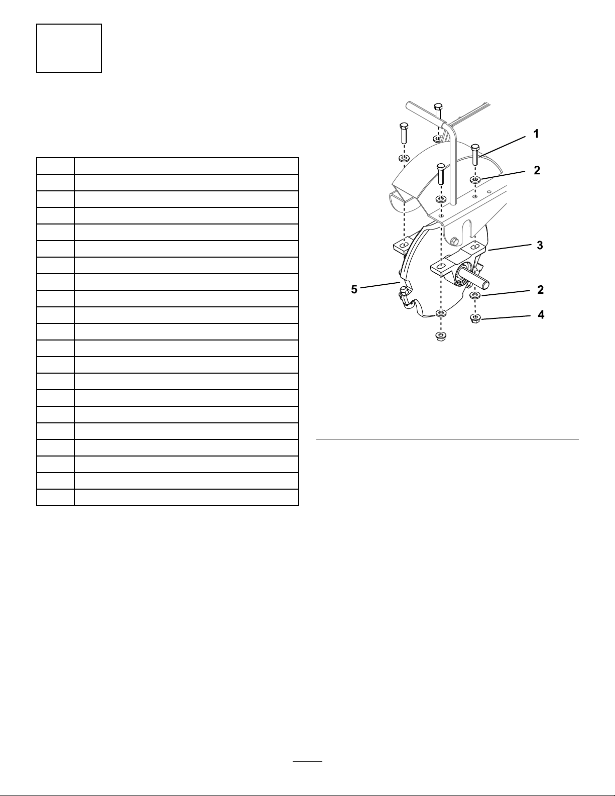
1.Slideabearingassemblyontotheshafton
bothsidesofthecutterwheelandfollow
theinstructionsprovidedwiththebearing
assemblies(Figure7).
Figure7
1.Bolt—3/8x1-1/2inches
(4)
2.Washer—0.40x0.81x
0.11inches(8)
3.Bearingassembly(2)
2.Securethebearingstotheframeofthemachine
using4bolts(3/8x1-1/2inches),8washers
(0.40x0.81x0.11inches),and4locknuts(3/8
inch)asshowninFigure7.T orqueto60to76
N∙m(44to56ft-lb).
4.Locknut—3/8inch(4)
5.Cutterwheel
g238743
5
Page 6
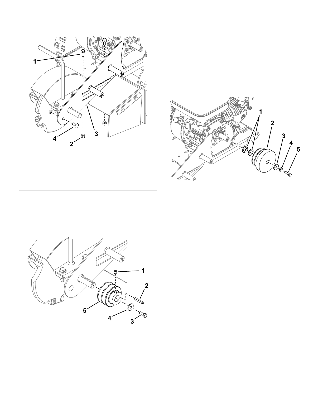
3.Installtheguardplateusing2angebolts(5/16
x3/4inch),1carriagebolt(5/16x3/4inch)and
3locknuts(5/16inch)asshowninFigure8.
Figure8
5.Applythread-lockingcompoundtothesetscrew,
andsecurethepulleywiththesetscrew,washer
(0.27x0.89x0.09inches),andbolt(1/4x3/4
inch)asshowninFigure9.T orquethesetscrew
to14.9to17.6N∙m(132to156in-lb).
6.Applythread-lockingcompoundtothebolt(5/16
x1-1/8inch)andusethebolt,2washers(0.76
x1.26x0.07inches),1washer(0.32x1.12x
0.18inches),and1washer(0.31x0.78x0.07
inches)toinstalltheclutchpulley(Figure10).
Torquetheboltto22.6to28.2N∙m(200to250
in-lb).
g239138
1.Flangebolt—5/16x3/4
inch(2)
2.Locknut—5/16inch(3)4.Carriagebolt(5/16x3/4
3.Guardplate
inch)
4.Applythread-lockingcompoundtothebolt(1/4x
3/4inch)andusethebolt,washer(0.27x0.89x
0.09inches),andsquarekeytoinstallthefront
pulley,withthepulleyfaceushwiththeendof
theshaft(Figure9).T orquetheboltto13.6N∙m
(120in-lb).
Figure10
1.Washer(0.76x1.26x0.07
inches)
2.Clutchpulley5.Bolt(5/16x1-1/8inch)
3.Washer(0.32x1.12x0.18
inches)
4.Washer(0.31x0.78x0.07
inches)
7.Installthebeltaroundthefrontpulleyandclutch
pulley(Figure13).
g247148
Figure9
1.Setscrew4.Washer(0.27x0.89x0.09
2.Squarekey
3.Bolt(1/4x3/4inch)
inches)
5.Frontpulley
g239137
6
Page 7
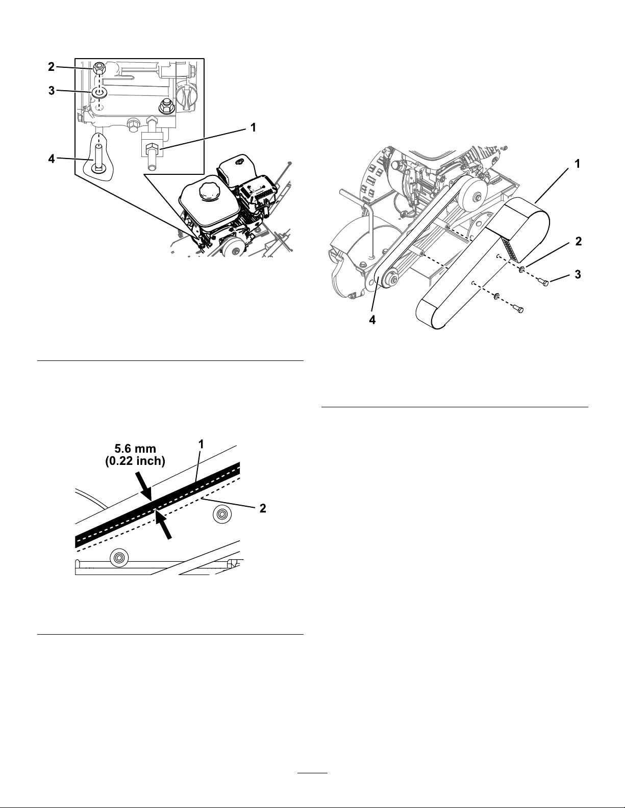
8.Tightenthejamnutonthetensionerbolt(Figure
11).
Figure11
Frontfastenersshown
10.Installortightenthefastenerssecuringthe
enginetotheframe(Figure11).
Note:Ensurethattheenginedoesnottwistin
thechassisandtheclutchpulleyisalignedwith
thebelt.
11.Installthebeltguardusing2bolts(3/8x1inch)
and2washers(0.38x0.75x0.08inches)as
showninFigure13.
g247150
1.Jamnut3.Washer—0.38x0.73x
0.07inches(4)
2.Locknut—5/16inch(4)4.Carriagebolt—5/16x
1-1/2inches(4)
9.Pushdownonthebelttocheckthetension
(Figure12).Youshouldbeabletopushthebelt
down5.6mm(0.22inch)using3.4kg(7.4lb)of
force.Adjustthetensionerboltasnecessaryto
tightenorloosenthebelt.
Figure12
g247149
Figure13
1.Beltguard
2.Washer—0.38x0.75x
0.08inches(2)
g240299
3.Bolt(3/8x1inch)
4.Belt
1.Beltwithoutforce2.Beltwith3.4kg(7.4lb)of
force
7
Page 8
5
InstallingtheDecal
Model138-3125Only
Partsneededforthisprocedure:
1Decal
Procedure
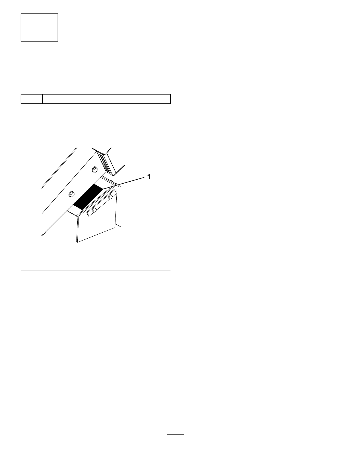
Installanewdecalovertheexistingdecalonthewing
bracketasshowninFigure14.
g240034
Figure14
1.Decal
8
 Loading...