

Page 1
FormNo.3412-574RevA
AdjustableStopBracketKit
2016andBeforeTurfMasterWalk-BehindLawnMower
ModelNo.136-7055
InstallationInstructions
WARNING
CALIFORNIA
Proposition65Warning
ThisproductcontainsachemicalorchemicalsknowntotheStateofCaliforniato
causecancer,birthdefects,orreproductiveharm.
Theadjustablestopbracketkitpreventsthetransmissionfromtippingtothepointwherethetransmissionbeltcomesoff.
Installation
LooseParts
Usethechartbelowtoverifythatallpartshavebeenshipped.
ProcedureDescription
1
2
Nopartsrequired
Adjustablestopbracket1
Bumper1
Hex-headbolt1
Flangenut1
1
RemovingtheExistingStop
Bracket
NoPartsRequired
Procedure
Qty.
–
5.Tipthemachineontoitsside,withtheairlterfacing
upward,untiltheupperhandlerestsontheground.
Removetheexistingstopbracket.
Installtheadjustablestopbracket.
Use
DANGER
Tippingthemachinemaycausethefuelto
leak.Fuelisammableandexplosive,and
cancausepersonalinjury.
Runtheenginedrytoremovethefuelwitha
handpump;neversiphonthefuel.
1.Movethemachinetoalevelsurface.
2.Releasetheblade-brakebail.
3.Disconnectthespark-plugwirefromthesparkplug.
4.Usethefrontandrearcutting-heightleverstoadjust
themachinetothelowestheight-of-cut.
Note:Adjustingthemachinetothelowest
height-of-cutallowsaccesstothestopbracket
mountingbolt.
©2016—TheToro®Company
8111LyndaleAvenueSouth
Bloomington,MN55420
Registeratwww.T oro.com.
OriginalInstructions(EN)
PrintedintheUSA
AllRightsReserved
*3412-574*A
Page 2
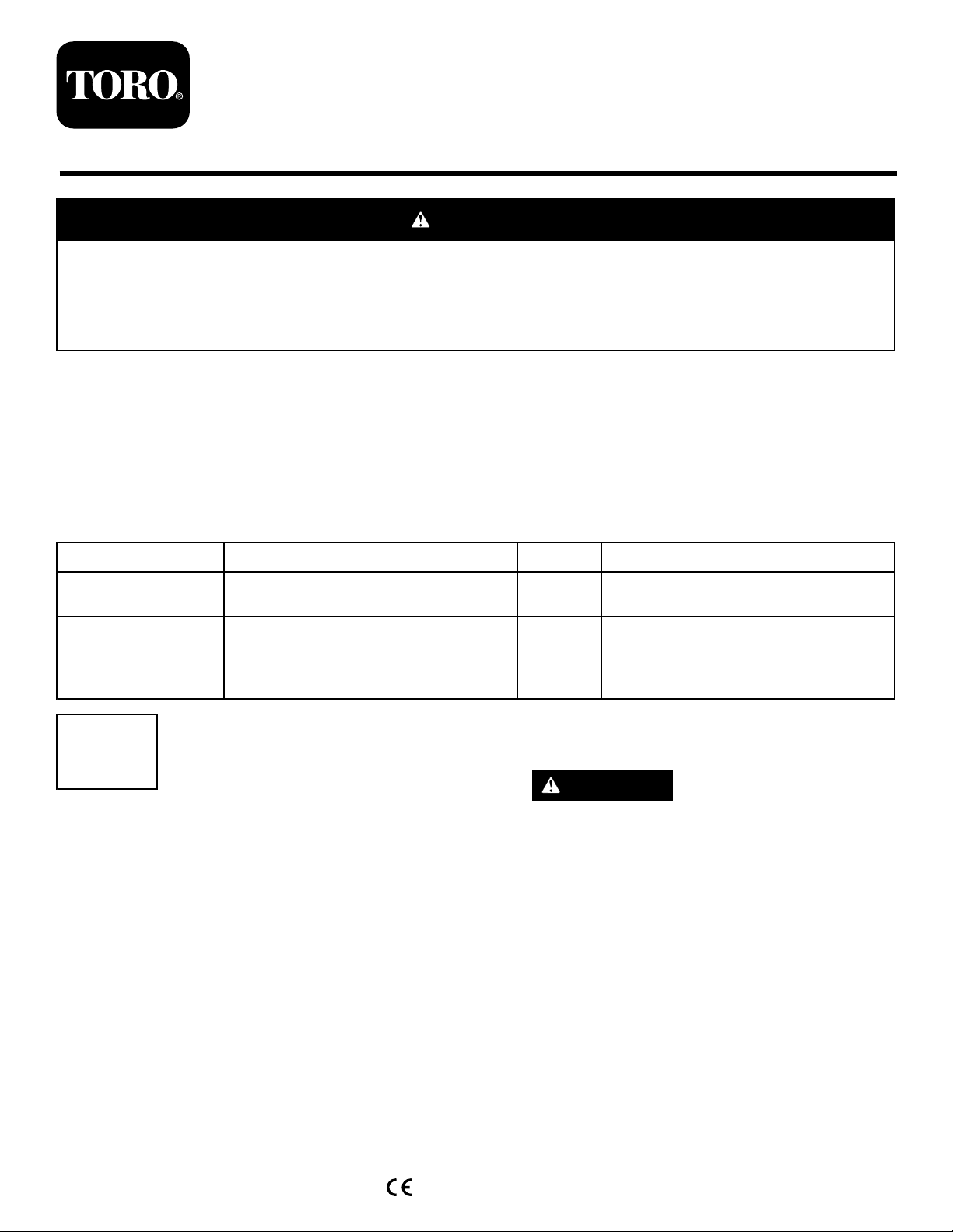
6.Useablockofwoodtoholdeachbladesteady(Figure
1).
Figure1
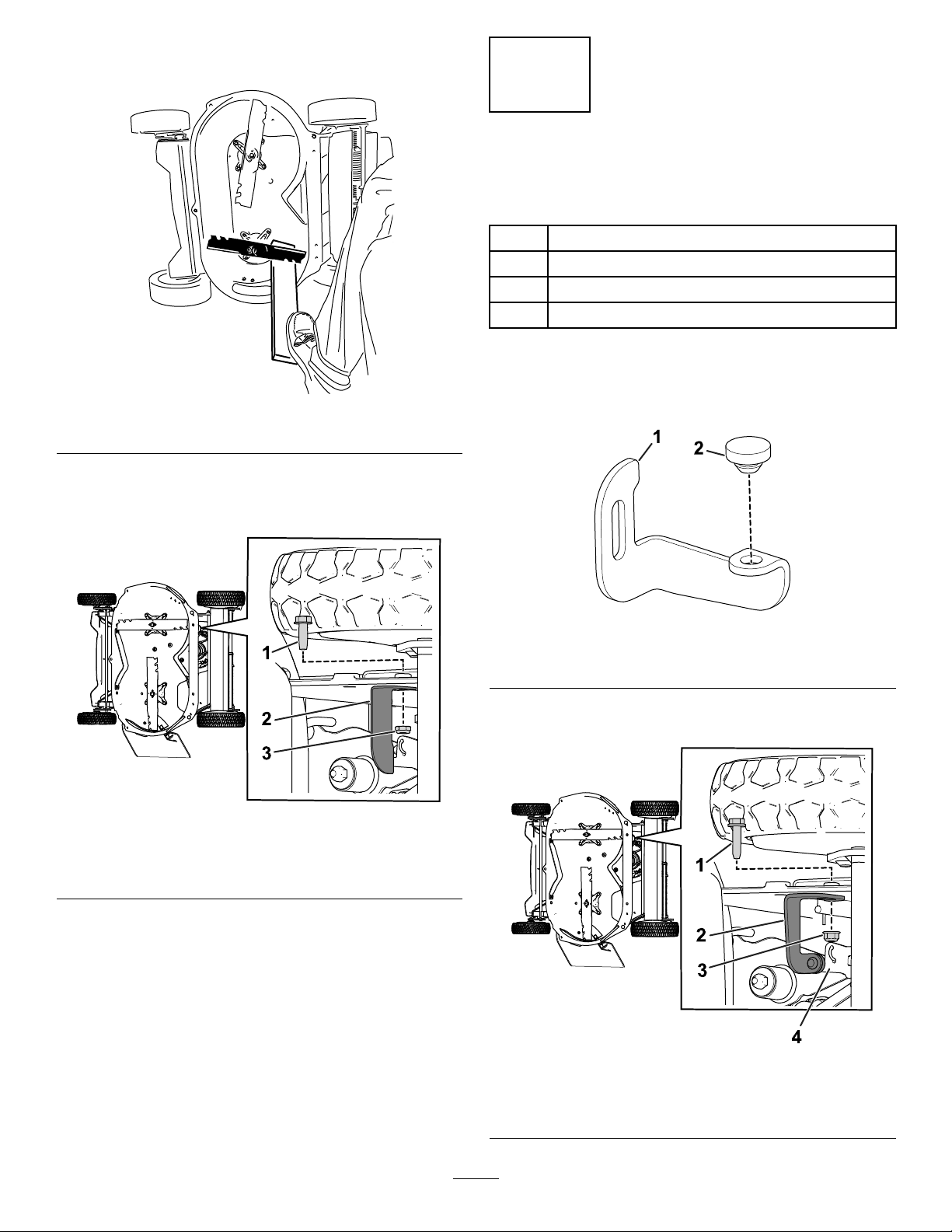
7.Removetheexistingstopbracketfromthemachineby
removingtheboltandthenutthatsecuresthebracket
tothemachine(Figure2).
2
InstallingtheAdjustableStop
Bracket
Partsneededforthisprocedure:
1Adjustablestopbracket
1Bumper
1Hex-headbolt
1Flangenut
Procedure
g197426
1.Attachthebumpertotheadjustablestopbracket
(Figure3).
Figure2
1.Bolt3.Nut
2.Existingstopbracket
g196914
Figure3
1.Adjustablestopbracket2.Bumper
2.Usethehex-headboltandtheangenuttoinstallthe
bracketontothemachine(Figure4).
g197398
g197411
Figure4
1.Hex-headbolt3.Flangenut
2.Bracket4.Transmission
2
Page 3

3.Adjustthebracketsothatthebumpercontacts,but
doesnotpresson,thetransmission(Figure5).
Figure5
1.Bumper2.Transmission
4.Torquetheboltto16to20N∙m(145to175in-lb).
g199058
5.Torquethenutto17to19N∙m(150to170in-lb).
6.Removetheblockofwoodfromtheblades,connect
thespark-plugwiretothesparkplug,andaddfuelto
thefueltank.
3
Page 4

 Loading...