

Page 1
FormNo.3422-409RevB
TrackCompletionKit
TX1000NarrowTrackCompactToolCarrier
ModelNo.136-4840
InstallationInstructions
Installation
2
RemovingtheCovers
1
PreparingtheMachine
NoPartsRequired
Procedure
WARNING
Mechanicalorhydraulicjacksmayfailto
supportthemachineandcauseseriousinjury.
Usejackstandswhensupportingthe
machine.
1.Removeanyattachmentsfromthemachine.
2.Parkthemachineonalevelsurface.
3.Engagetheparkingbrake.
4.Raisetheloaderarmsandsecurethemwiththe
cylinderlocks.
5.Shutofftheengine,removethekey,andwait
forthemachinetocool.
NoPartsRequired
RemovingtheFrontScreen
1.Openthehoodandsecurethehoodprop.
2.Loosenthe2topboltsandremovethe2front
bolts.
6.Raisethemachineoffthegroundsothatyou
canaccessunderneaththemachine.Support
themachineusingjackstands.
Note:Usejackstandsratedforyourmachine.
RefertotheOperator’sManualforyourmachine
todeterminetheweight.
©2018—TheToro®Company
8111LyndaleAvenueSouth
Bloomington,MN55420
Registeratwww.T oro.com.
Figure1
1.Topbolt2.Frontbolt
3.Removethescreen.
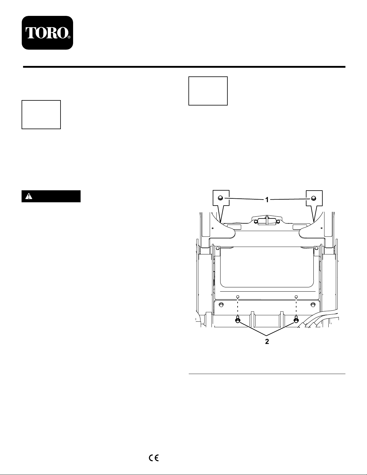
RemovingtheFrontCover
1.Removethe2upperbolts(3/8x1inch),2
washers,and2lowerbolts(5/16x5/8inch)from
thefrontcover.
2.Removethefrontcover(Figure2).
OriginalInstructions(EN)
PrintedintheUSA
AllRightsReserved
*3422-409*B
g262277
Page 2

3
RemovingtheExisting TrackAssemblies
NoPartsRequired
Procedure
1.Placeragsoracontainerunderthetrack
motorhydraulicportstocatchanyuidasyou
completethisprocedure(Figure4).
Figure2
1.Upperbolt—3/8x1inch
(2)
2.Frontcover
3.Washer(2)
4.Lowerbolt—5/16x5/8
inch(2)
RemovingtheBottomCoverPlate
1.Removethe2bolts(3/8x1inch)thatsecurethe
bottomcoverplatetotheframeplate(Figure3).
g256988
2.Markthehosesconnectedtothemotorswith
theirportlocations(i.e.,leftfront,leftrear,right
front,rightrear).
g257080
Figure4
1.Hose(4)3.Port(4)
2.Trackmotor(2)
3.Removethehosefrom1trackmotorandinstall
protectivecoversoverthehoseopenings.
4.Removethehydraulicttingsfromthemotor.
Figure3
1.Bolts(3/8x1inch)
2.Removethebottomcoverplatefromthe
machine(Figure3).
2.Bottomcover
g247034
2
Page 3
5.Removethenutfromthefronttrackpinshown
inFigure5.
Note:Donotremovethepinatthistime.
Figure5
1.Trackpin2.Nut
6.Loosentherearboltsecuringthereartrack
frametothemachine(Figure6).
g257082
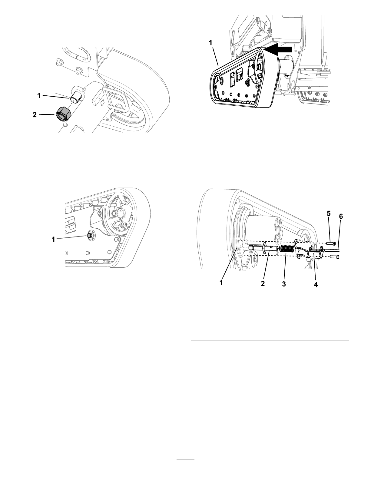
Figure7
1.Trackassembly
g257083
8.Removethebrakemountassemblyfromthe
motorasfollows:
A.Removeandretainthe2boltssecuring
thebrakemounttothetrackmotorcasting
(Figure8).
Figure6
1.Rearbolt
7.Usingahoistorforkliftcapableoflifting181kg
(400lb),slidethetrackassemblyfromtheframe
about15cm(6inches)asshowninFigure7.
Important:Ensurethatthehydrauliclines
areoutoftheway.
g257081
g259801
Figure8
1.Trackmotorcasting4.Brakemount
2.Brake-shaftpin5.Bolt—3/8x1-1/4inches
3.Compressionspring
(2)
6.Brakecable
B.Loosenthenutssecuringthebrakecableto
thebrakemount(Figure8).Removethe
brakecables.
C.Removeandretainthecompressionspring
(Figure8).
9.Completelyremovethetrackassemblyfromthe
machine.
10.Repeattheprocedurefortheothertrack.
3
Page 4
4
InstallingtheNewTrack Assemblies
barrelttingofthebrakecableintotheslot
inthepin,slidethecableintothemount
notchsothatthenotchisbetweenthe2
cablenuts,andslowlyreleasethepinand
spring.
C.Adjustthenutsonthebrakecablesothat
only2threadsshowtowardthecable
(Figure9).
Partsneededforthisprocedure:
2
Trackassembly(soldseparately)
2Brakemount
2
Brake-shaftpin
1
Brakekit(soldseparately)
Procedure
1.Usingahoistorforkliftcapableoflifting181kg
(400lb),liftthetrackassemblytoapproximately
15cm(6inches)awayfromthemachine.
2.Ifyouareinstallingaseparatebrakekit,refer
totheInstallationInstructionsforthekit(see
ServiceBulletin110),thencontinuetostep3.
Important:Usethebrakemountsandpins
providedinthistrackkit.Donotusethe
brakemountsandpinsprovidedintheBrake
Kit.
Ifyouarenotinstallingaseparatebrakekit,
continueasfollows.
A.Insertthebrakecablethroughthebrake
mountandspring,andinsertthebarrel
ttingintotheslotofthebrake-shaftpin
(Figure9).
D.Tightenthenuts.
E.Securethebrakemounttothemotor
mount,withtheopensidefacingtowardthe
trackmotor,usingthe2boltsyouremoved
previously(Figure10).
Figure10
1.Brakemount
3.Installthetrackassemblyandsecureittothe
mainframeusingthebolt,washer,pin,andnut
removedfromthetrackassemblies(Figure11).
2.Bolt—3/8x1-1/4inches
(2)
g259847
Figure9
1.Brake-shaftpin
2.Compressionspring
3.Brakemount
B.Insertthebrake-shaftpinintothespringand
thenintothebrakemount(Figure9).Push
inthepintocompressthespring,insertthe
4.Brakecable
5.Nut
6.Barreltting
g261347
Figure11
1.Nut4.Washer
2.Pin5.Trackassembly
3.Bolt
4.Torquethefrontnutto244to298N∙m(180to
220ft-lb)andtorquetherearboltto305to373
N∙m(225to275ft-lb).
4
g257331
Page 5

5.Placeragsoracontainerunderthetrackmotor
hydraulicportstocatchanyuid.Removethe
plugsfromtrackmotor.
6.InspectandreplaceanydamagedO-ringson
thehydraulicttings.
7.Installthehydraulicttingsintothenewtrack
motors(Figure12).T orquethemto136to163
N∙m(100to120ft-lb).
Figure12
1.Hose(4)3.Trackmotor(2)
2.Fittinginstalledintothe
port(4)
g260318
Figure13
g257334
1.Hoses
8.Installthehosestotheportsthatyoumarked
(Figure12).
9.Torquethehosesto50to64N∙m(37to47ft-lb).
10.Repeattheprocedurefortheothertrack.
11.Inthefrontofthemachine,removethe2hoses
onthetandempumpandinstallthemtothe
oppositeports(Figure13).T orquethettingsto
24to30N∙m(18to22ft-lb).
5
Page 6

5
ReplacingtheReliefValves
Partsneededforthisprocedure:
4
Reliefvalve
Procedure
3.Install2newreliefvalvesintheirplaceand
torquethemto34to39N∙m(25to29ft-lb).
g257483
Figure15
1.Usepressurizedairtocleanthecavitiesofeach
reliefvalvebeforeremovingthem.
2.Usea15mmsockettoremovetheexistingtop
reliefvalvesfromthetandempump(Figure14).
4.Placeragsortowelsunderthetandempumpto
catchuidfromthehosesandtting.
5.Loosenthe2hoseclampsandremovethe
hosesfromthetting(Figure16).
Figure16
1.Nut
2.Hoseclamp(2)
3.Hose(2)
g257482
1.Tandempump
6.Cleantheareaaroundthetting.
7.Usea1-1/4inchcrowfootoropen-endwrenchto
loosenthenutonthettingshowninFigure16.
g257481
Figure14
2.Topreliefvalve(2)
6
Page 7

8.Rotatethettingcounterclockwisesothatthe
atsideofthettingalignswiththereliefvalve
portopening(Figure17).
Figure17
6
InstallingtheCovers
NoPartsRequired
InstallingtheBottomCoverPlate
1.Alignthetabofthebottomcoverplatewiththe
frameplateofthemachine(Figure18).
g258053
1.Fitting
9.Removethe2lowerreliefvalves(Figure17).
10.Install2newvalvesintheirplaceandtorque
themto34to39N∙m(25to29ft-lb).
11.Rotatethettingtotheoriginalorientation
(Figure16).Torquethenutto182to222N∙m
(134to164ft-lb).
12.Installthehosesandhoseclamps(Figure16).
2.Lowerreliefvalve(2)
Figure18
1.Bottomcoverplate
2.Aligntheholesinthebottomcoverplatewiththe
frameplate(Figure18).
3.Assemblethebottomcoverplatetotheframe
plate(Figure18)withthe2capscrews(3/8x1
inch)thatyouremovedpreviously.
2.Capscrew(3/8x1inch)
g247051
7
Page 8

InstallingtheFrontCover
InstallingtheFrontScreen
Installthefrontcoverusingthe2bolts(3/8x1inch),
2washers,and2bolts(5/16x5/8inch)thatyou
removedpreviously(Figure19).
Figure19
1.Upperbolt—3/8x1inch
(2)
2.Frontcover
3.Washer(2)
4.Lowerbolt—5/16x5/8
inch(2)
1.Installthefrontscreenusingthe4bolts(3/8x1
inch)youremovedpreviously(Figure20).
g247902
g256988
1.Bolt—3/8x1inch(2)
Figure20
2.Lowerthemachinetotheground.
8
Page 9

7
InstallingtheHandle
Partsneededforthisprocedure:
1Handle
2Bolt
2Nut
Procedure
4.Installthenewhandleusing2boltsand2nuts
(Figure23).
1.Opentherear-accesscover.
2.Removeandretainthe4boltsandnutssecuring
thecontrolpanelcovertothemachine(Figure
21).
Figure21
1.Boltandnut(4)
3.Liftupthecontrolpanelcoverandremovethe
fronthandle(Figure22).
g257389
Figure23
1.Bolt(2)3.Nut(2)
2.Handle
5.Securethecontrolpanelcoverusingthe4bolts
and4nutsyouremovedpreviously.
6.Closetherear-accesscover.
g257391
Figure22
1.Handle2.Bolt
g257390
9
Page 10

Maintenance
5.Usinga1/2inchdriveratchet,turnthetensioning
screwuntilthetrackgapis13mm(1/2inch)as
showninFigure24.
AdjustingtheTrackTension
Lift/support1sideofthemachineandusingtheweight
ofthetrack,verifythatthegapbetweenthebottom
ofthelipoftheroadwheelandthetrackis13mm
(1/2inch)asshowninFigure24.Ifitisnot,adjustthe
tracktensionusingthefollowingprocedure.
Figure24
1.Roadwheel
1.Parkthemachineonalevelsurface,engagethe
parkingbrake,andlowertheloaderarms.
Note:Turningthescrewcounter-clockwise
tightensthetrack;turningthescrewclockwise
loosensthetrack.
6.Aligntheclosestnotchinthetensionscrewto
thelocking-boltholeandsecurethescrewwith
thelockingboltandnut(Figure25).
7.Repeattheprocedurefortheothertrack.
8.Drivethemachine,thenparkthemachineona
levelsurface,engagetheparkingbrake,shutoff
theengine,andremovethekey.
9.Verifythatthetrackdeectionis13mm(1/2
inch)asshowninFigure24.Adjustifnecessary.
ReplacingtheTracks
Replacethetrackswhentheyarebadlyworn.
g257979
RemovingtheTracks
1.Removeanyattachments.
2.Parkthemachineonalevelsurface,ensuring
thatonly1sprockethalfisengagedwiththe
track(Figure26).
2.Shutofftheengineandremovethekey.
3.Raisethesideofthemachinethatyouare
adjustingsothatthetrackisofftheground.
4.Removethelockingbolt,spacer,andnut(Figure
25).
Figure25
1.Lockingbolt
2.Tensioningscrew4.Nut
3.Spacer
g259714
Figure26
1.Sprockethalf
3.Engagetheparkingbrake.
4.Lowertheloaderarmssothattheyare
g257903
approximately20to25cm(8to10inches)
abovetheframe.
5.Shutofftheengineandremovethekey.
6.Liftthesideofthemachinewiththetrackyou
arereplacing.Supportthemachineusingjack
stands.
Note:Usejackstandsratedforyourmachine.
10
Page 11

WARNING
Mechanicalorhydraulicjacksmayfailto
supportthemachineandcauseserious
injury.
Usejackstandswhensupportingthe
machine.
7.Removethelockingbolt,spacer,andnut(Figure
25).
8.Usinga1/2-inchdriveratchet,releasethe
drivetensionbyturningthetensioningscrew
clockwise(Figure25andFigure27).
11.Movethetractioncontrolforwarduntiltheother
halfofthedrivesprocketisnotengagedwith
thetrack(Figure29).
g259736
Figure29
12.Engagetheparkingbrake,shutofftheengine,
andremovethekey.
13.Removethetrackfromthetrackframe,drive
hub,thenfrontwheel.
Figure27
1.Sprocket4.Ratchet(1/2inch)
2.Track
3.Frontwheel
5.Roadwheel(5)
9.Removethe3boltssecuringthesprockethalf
thatisnotengagedwiththetrack(Figure28).
InstallingtheTracks
1.Wrapthenewtrackaroundthefrontwheel,then
wrapthetrackaroundthedrivehubontheside
withoutthesprocket(Figure27).
g258146
2.Pushthetrackunderandbetweentheroad
wheelsandwrapitaroundthelowerframe
(Figure27).
Note:Ensurethattheroadwheelsarecentered
onthetrack.
3.Starttheengineanddisengagetheparking
brake.
4.Movethetractioncontrolforwarduntilthedrive
sprockethalfengageswiththetrack(Figure30).
Figure28
1.Bolt(3)2.Sprockethalf
10.Startthemachineanddisengagetheparking
brake.
g259737
g257925
Figure30
5.Engagetheparkingbrake,shutofftheengine,
andremovethekey.
6.Applythread-lockingcompoundtotheboltsof
thedrivesprockethalfthatyouremovedand
11
Page 12

installthesprockethalf(Figure28).Torquethe
boltsto95to115N∙m(70to85ft-lb).
7.Usinga1/2inchdriveratchet,turnthetensioning
screwcounter-clockwiseuntilthetrackdeection
is13mm(1/2inch)asshowninFigure24.
8.Aligntheclosestnotchinthetensionscrewto
thelockingboltholeandsecurethescrewwith
thelockingbolt,spacer,andnut.
9.Lowerthemachinetotheground.
10.Repeattheproceduretoreplacetheothertrack.
11.Drivethemachine,thenparkthemachineona
levelsurface,engagetheparkingbrake,shutoff
theengine,andremovethekey.
12.Verifythatthetrackdeectionis13mm(1/2
inch)asshowninFigure24.
12
 Loading...