

Page 1

BrakeKit
TX1000CompactToolCarrier
ModelNo.136-4799
Installation
LooseParts
Usethechartbelowtoverifythatallpartshavebeenshipped.
FormNo.3422-159RevA
InstallationInstructions
ProcedureDescription
1
2
3
4
5
6
7
8
Nopartsrequired
Nopartsrequired
Brakebracketassembly1
Bolt(5/16x1inch)
Nut(5/16inch)
Spring
Brakemount2
Bolt(3/8x1-1/4inches)
Cabletie
Nopartsrequired
Cabletie
Nopartsrequired
Qty.
Use
–
–
2
2
1
4
1
–
1
–
Removetheaccesspanels.
Removetheexistingbrakeassembly.
Assemblethecablestothebrake-mount
plate.
Installthebrakebracketassembly.
Installthebrakemounts.
Adjustthebrakecables.
Completetheinstallation.
Installthecoverplates.
©2018—TheT oro®Company
8111LyndaleAvenueSouth
Bloomington,MN55420
Registeratwww.T oro.com.
OriginalInstructions(EN)
PrintedintheUSA
AllRightsReserved
*3422-159*A
Page 2
1
RemovingtheCoverPlates
NoPartsRequired
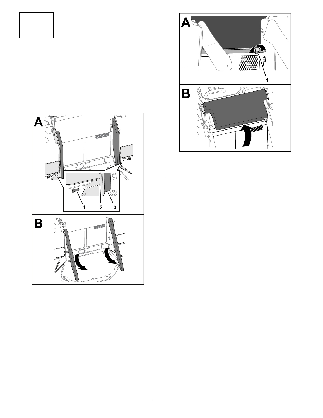
RotatingtheSideandFrontPads
1.Removethebottom2bolts(5/16x3/4inch)that
securetheleftandrightsidepadstotheframe
plates(Figure1).
g247038
Figure2
1.Captivebolt
4.Rotatethepadup(Figure2).
Figure1
1.Bolts(5/16x3/4inch)3.Sidepad
2.Frameplate
2.Rotatethepadsup(Figure1).
3.Loosenthecaptiveboltthatsecuresthefront
padtothescreenframe(Figure2)
g247039
2
Page 3
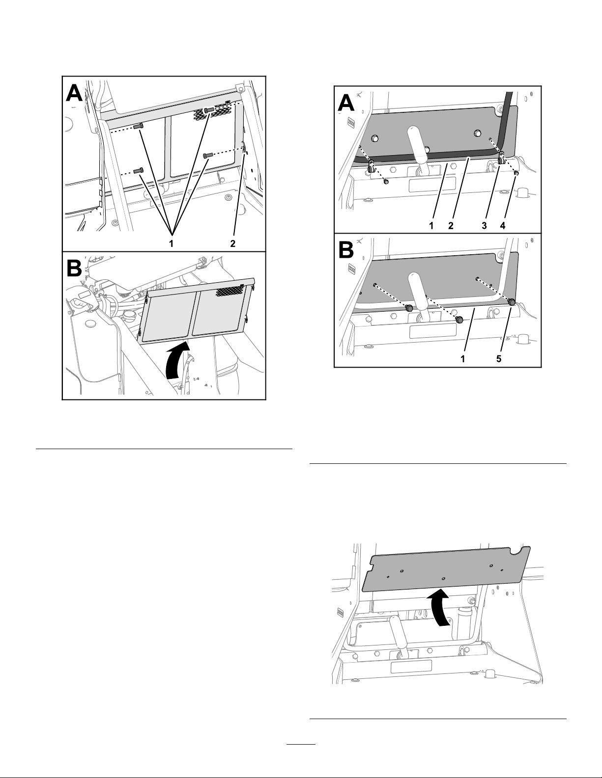
RemovingtheScreen
RemovingtheRear-CoverPlate
1.Removethe4bolts(3/8x7/8inch)thatsecure
thescreenframetotheframeplates(Figure3)
1.Removethe2ange-headbolts(1/4x1/2inch)
and2clampsthatsecurethefuelhosetothe
rear-coverplate(Figure4).
Figure3
1.Bolts(3/8x7/8inch)2.Screenframe
2.Removethescreenframefromthemachine
(Figure3).
g247035
Figure4
g247037
1.Rear-coverplate
2.Fuelhose
3.Clamp
4.Flange-headbolt(1/4x
1/2inch)
5.Flange-headbolt(5/16x
5/8inch)
2.Removethe3ange-headbolts(5/16x5/8
inch)thatsecuretherear-coverplatetothe
rear-frameplate(Figure4).
3.Removetherear-coverplatefromthemachine
(Figure5).
g247036
Figure5
3
Page 4
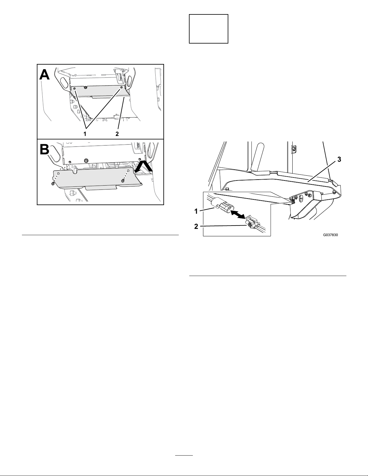
RemovingtheBottom-Access
Plate
1.Removethe2capscrews(3/8x1inch)that
securethebottomcoverplatetotheframeplate
(Figure6).
2
RemovingtheExisting
BrakeAssembly
NoPartsRequired
Procedure
1.Beneaththeoperator’splatform,unplugthe
auxiliary-switchwireharnessfromthemainwire
harnessofthemachine(Figure7).
Figure6
1.Capscrew(3/8x1inch)
2.Removethebottomcoverplatefromthe
machine(Figure6).
2.Bottomcoverplate
g247034
g037830
Figure7
1.Mainwireharness
2.Auxiliary-switchharness
2.Disconnectthewireharnessfromthebrake
switch.
3.Removethe2bolts,2nuts,andbrakelever
assembly(Figure8).
3.Operator’splatform
4
Page 5

Figure10
g240461
Figure8
1.Nut(2)3.Bolt(2)
2.Brakeleverassembly
4.Removeandretainthebrakeswitchand
fastenersfromtheassembly(Figure9).
1.Trackmotorcasting
2.Brake-shaftpin
3.Compressionspring
g242415
B.Removeandretainthecompressionspring
andbrake-shaftpin(Figure10).
C.Loosenthenutssecuringthebrakecableto
thebrakemount(Figure10).Removethe
brakecables.
4.Bolt(2)
5.Brakemount
6.Brakecable
3
AssemblingtheCablesto
theBrake-MountPlate
Partsneededforthisprocedure:
1Brakebracketassembly
Figure9
1.Screw(2)3.Jamnut(2)
2.Brakeswitch
5.Removethebrakemountassemblyfromboth
sidesofthemachineasfollows:
A.Removethe2boltssecuringthebrake
mounttothetrackmotorcasting(Figure
10).
Procedure
g241737
1.Slidethecablewiperoffthethreadedconduit
ttingandthreadtheendjamnutoffthetting
(Figure1 1).
5
Page 6

Figure11
1.Cablewiper4.Cable
2.Jamnut5.Brake-mountplate
3.Threadedconduittting
2.Alignthecablethroughslotinthebrake-mount
plateandslidethethreadedconduittting
throughthebracket(Figure11).
3.Threadtheendjamnutontothettingthreaded
conduittting(Figure12).
g247371
g247370
1.Cablewiper
2.Jamnut
4.Adjustthepositionofthejamnutstocenter
thethreaded-conduitttingtothebrake-mount
plate,andtightenthejamnuts(Figure12).
5.Slidethecablewiperovertheendofthe
threaded-conduittting(Figure12).
6.Repeatsteps1through5fortheotherbrake
cable(Figure11andFigure12).
Figure12
3.Brake-mountplate
4
InstallingtheBrakeBracket
Assembly
Partsneededforthisprocedure:
2
Bolt(5/16x1inch)
2
Nut(5/16inch)
1
Spring
Procedure
1.Installthebrakeswitchtothenewbrakebracket
assembly(Figure9).
Note:Ensurethattheplungerhousingisush
withorslightlyinsidetheedgeofthebrake
bracket.
6
Page 7

2.Frominsidethemachine,insertthebrake
handlethroughtheholeintherearplatesothat
thehandlepointsupward.
3.Securethebrakebracketassemblyusing2
bolts(5/16x1inch)and2nuts(5/16inch)as
showninFigure13.
g242891
Figure14
Figure13
1.Nut—5/16inch(2)2.Bolt—5/16x1inch(2)
5
1.Brake-shaftpin
2.Compressionspring
3.Brakemount
4.Brakecable
5.Nut
6.Barreltting
2.Insertthebrake-shaftpinintothespringand
thenintothebrakemount(Figure14).Pushin
thepintocompressthespring,insertthebarrel
ttingofthebrakecableintotheslotinthepin,
slidethecableintothenotchinthebrakemount,
andslowlyreleasethepinandspring.
3.Tightenthenutsonthebrakecable.
4.Securethebrakemounttothemotormount,
withtheopensidefacingtowardtheoperator’s
g242428
platform,using2bolts(3/8x1-1/4inches)as
showninFigure15andFigure16.
Note:Ensuretoroutethecablestotheinside
oftheoilcoolerandradiatorhoses(Figure16).
InstallingtheBrakeMounts
Partsneededforthisprocedure:
2Brakemount
4
Bolt(3/8x1-1/4inches)
1
Cabletie
Procedure
1.Loosenthenutsontheendofthebrakecable
withthebarreltting.Insertthecablethrough
thebrakemountandspring,andinsertthe
barrelttingintotheslotofthebrake-shaftpin
(Figure14).
Figure15
1.Brakemount
1.Hose2.Brakecable
2.Bolt—3/8x1-1/4inches
(2)
Figure16
5.Repeattheprocedurefortheotherbrakemount
ontheothersideofthemachine.
g234347
g242491
7
Page 8

6.Routethemachinewireharnessandthebrake
switchharnessasshowninFigure17.Connect
thebrakeswitchtothemachinewireharness.
g240527
Figure18
Figure17
1.Brakeswitchconnector
2.Machinewireharness
(ConnectorP42)
7.Securethemachinewireharnesstotheupper
brakecableusingacabletie(Figure17).
3.Cabletie
6
AdjustingtheBrakeCables
NoPartsRequired
Procedure
1.Movetheparking-brakelevertotheONposition.
g242890
1.Trackmotorcasting2.Pin
5.Cycletheparkingbrakestoensurethey
consistentlyengageanddisengage.
7
ConnectingtheWire
Harness
Partsneededforthisprocedure:
1
Cabletie
Procedure
1.Plugtheauxiliary-switchwireharnesstothe
mainwireharnessofthemachine(Figure19).
2.Loosenthe2nutsonthepinsideofeachbrake
cableandadjustthecablesothatitistautand
thepinisushagainstthetrackmotorcasting
(Figure10).
Note:Adjustthenutstowardthepintomove
thepinfurtherinward;adjustthenutsawayfrom
thepintomovethepinfurtheroutward.
3.Movetheparking-brakelevertotheOFFposition.
4.Adjustthespringsideofeachbrakecableso
thatthecableistaut,butthepinisushwiththe
outsideofthetrackmotorcasting(Figure18).
1.Mainwireharness
2.Auxiliary-switchharness
8
g037848
Figure19
3.Operator’splatform
Page 9

2.Useacabletietosecuretheauxiliary-switch
wireharnesstotherightbrakecablesothat
theharnessdoesnotrubagainstorbecome
pinchedbetweenparts.
8
InstallingtheCoverPlates
NoPartsRequired
InstallingtheBottom-AccessPlate
InstallingtheRear-CoverPlate
1.Aligntheholesintherear-coverplatetothe
holesintherear-frameplate(Figure21).
1.Alignthetabofthebottomcoverplatewiththe
frameplateofthemachine(Figure20).
Figure20
1.Bottomcoverplate
2.Capscrew(3/8x1inch)
g247052
Figure21
1.Rear-coverplate
2.Assembletherear-coverplatetotherear-frame
plate(Figure22)withthe3ange-headbolts
(5/16x5/8inch)thatyouremovedinRemoving
theRear-CoverPlate(page3).
g247051
2.Rear-frameplate
2.Aligntheholesinthebottomcoverplatewiththe
frameplate(Figure20).
3.Assemblethebottomcoverplatetotheframe
plate(Figure20)withthe2capscrews(3/8
x1inch)thatyouremovedinRemovingthe
Bottom-AccessPlate(page4).
4.Torquethecapscrewsto37to45N∙m(27to33
ft-lb).
1.Rear-coverplate
2.Flange-headbolt(5/16x
5/8inch)
3.Fuelhose
9
g247054
Figure22
4.Clamp
5.Flange-headbolt(1/4x
1/2inch)
Page 10

3.Torquethe3ange-headboltto1978to2542
N∙cm(175to225in-lb).
4.Securethefuelhosetotherear-coverplatewith
the2clampsand2ange-headbolt(1/4x1/2
inch),andtightentheboltsbyhand(Figure22).
InstallingtheScreen
1.Aligntheholesinthemountingtabsofthe
screenframewiththeholesontheframeplates
(Figure23).
AssemblingthePads
1.Rotatethefrontpaddown(Figure24).
Figure23
1.Screenframe3.Mountingtab(screen
frame)
2.Bolts(3/8x7/8inch)
2.Assemblethescreenframetotheframeplates
(Figure23)withthe4bolts(3/8x7/8inch)that
youremovedinRemovingtheScreen(page3).
3.Torquetheboltsto7to45N∙m(27to33ft-lb).
g247057
Figure24
1.Frontpad
2.Captivebolt
2.Assemblethefrontpadtothescreenframewith
thecaptivebolt,andtightentheboltbyhand
(Figure24).
3.Rotatetheleftandrightsidepadsdown,and
alignthelowerholesinthepadswiththeholes
intheframeplates(Figure25).
4.Assemblethesidepadstotheframeplates
g247055
(Figure25)atthebottomholeswiththe2bolts
(5/16x3/4inch)thatyouremovedinRotating
theSideandFrontPads(page2).
10
Page 11

Figure25
g247058
1.Frameplate
2.Sidepads
3.Bolts(5/16x3/4inch)
4.Topbolts
5.Torquethe2boltsthatsecurethesidepadsto
theframeplatesto1978to2542N∙cm(175to
225in-lb).
11
Page 12

 Loading...