

Page 1

TF-T5000HD PVR
User Manual
High Definition
Digital Terrestrial Receiver
Personal Video Recorder
Default PIN: 2010
Full Guide is available at http://www.i-topfield.com
Page 2

.
2
Page 3
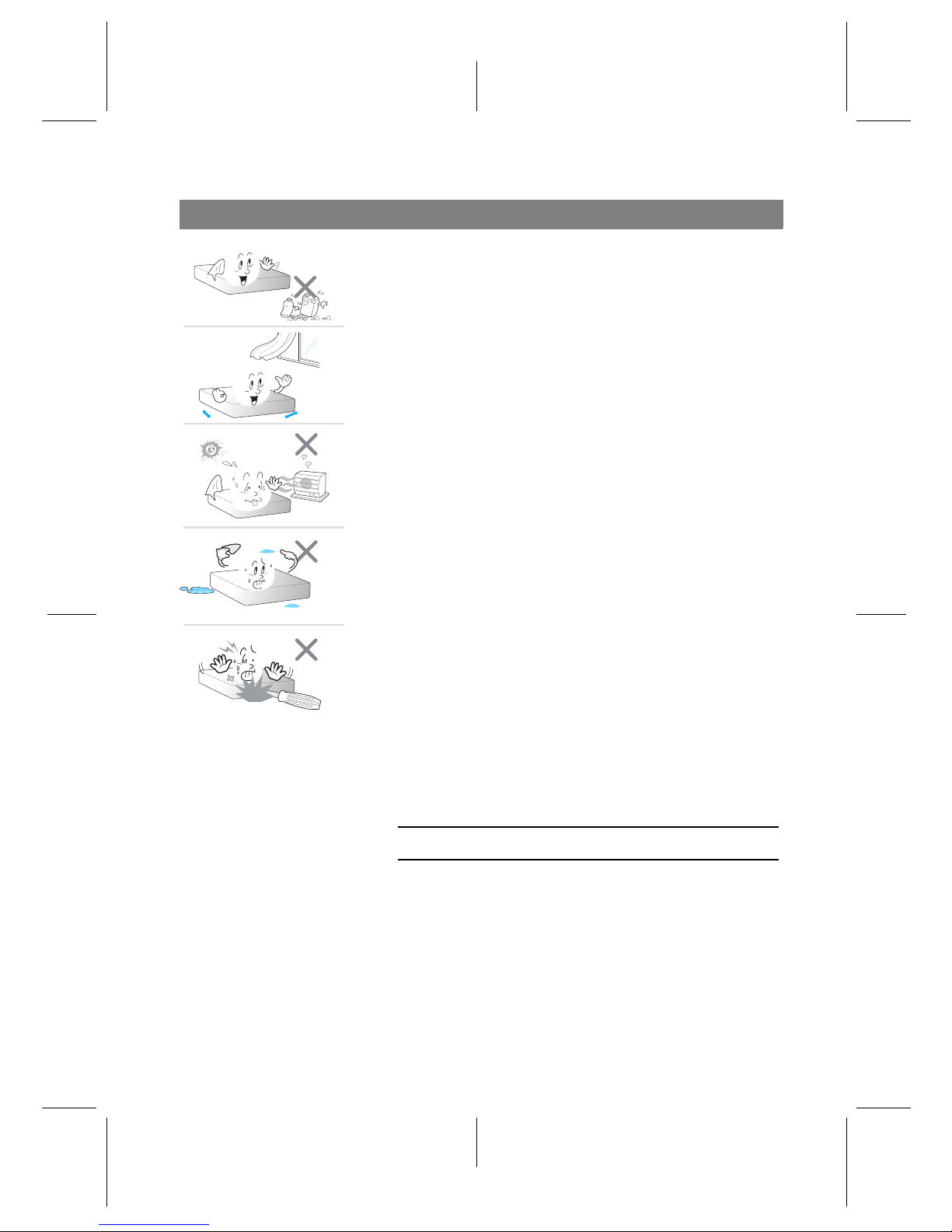
Precautions
• Clean with a dry cloth only.
• Do not block any of the ventilation openings.
• When placed in a cabinet, make sure there is a minimum
space of 10 centimetres around it.
• Do not install near any heat sources or in direct sunlight as
this will impair cooling.
• Do not operate this product near water.
• Do not try to change the plug or defeat its safety purpose.
• This product is designed for indoor use only.
• Place the digital receiver on a firm and level surface.
• Do not lay any objects such as magazines on this unit.
• Do not overload power outlets. Doing so may result in a risk
of fire or electrical shock.
• Never open this unit’s casing under any circumstances, or the
warranty will be void.
• Unplug this unit during lightning storms or when unused for
long periods of time.
• Refer all servicing to qualified service personnel. Reverse engineering or disassembly is prohibited.
• Batteries, including those which contain no heavy metals,
may not be disposed with other household wastes. Please dispose of used batteries in an environmentally sound manner.
Find out the legal regulations which apply in your area.
• The mains plug shall remain readily operable so that it can be
removed easily to disconnect the power.
• Operate the digital receiver at temperatures between 0 to
45◦C.
• Check the mains voltage before plugging the digital receiver
to the wall socket. For the power specification, refer to the
table below.
Input voltage 100 to 240 V AC, 50/60Hz
Power consumption 24 W at maximum in active
• This receiver does not support passive standby mode, since it
is a Complex set top box that features Ethernet.
3
Page 4
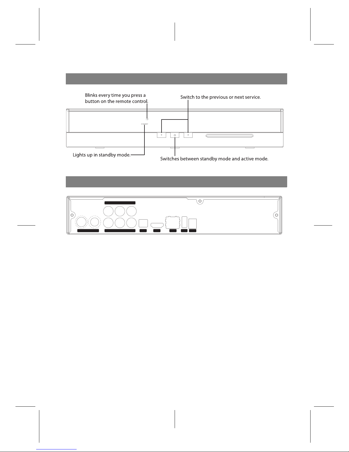
Front Panel
Rear Panel
HDMI USBLANS/PDIF DC IN
IN - ANT - OUT
VIDEOR - AUDIO - L
PrYPb
ANT IN Terrestrial broadcasting signal input socket
(5V, Max.100mA)
ANT OUT Terrestrial broadcasting signal output socket through the ANT IN socket
for another digital receiver
Y/Pb/Pr Component video output socket for the television set (green/blue/red)
AUDIO L/R Stereo audio output socket for the television set or the audio-video re-
ceiver
(white/red)
VIDEO Composite video output socket for the television set (yellow)
S/PDIF Digital audio output socket for the audio-video receiver
HDMI Audio and video output socket for the high definition television set
LAN Local area network port
USB port for firmware update/data transfer
(USB 2.0 Host, 5V DC, 500mA Max.)
DC IN Power jack
4
Page 5
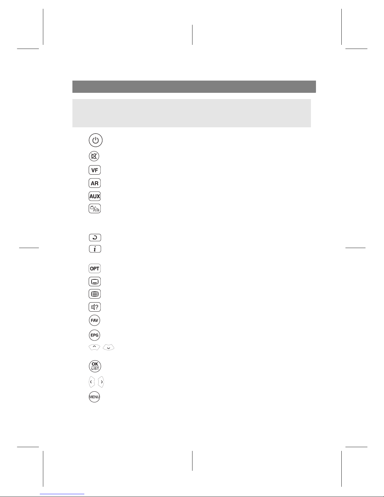
Remote Control
NOTE
The actual images and the number of buttons could be different depending on the type of
remote control provided by the manufacturer.
• button switches the digital receiver between standby mode and active mode.
• mutes the sound. Press again to switch it back on.
• changes video resolution.
• changes aspect ratio.
• not used in this model.
• switches over between television services and radio services.
• Numeric buttons are used to enter a service number for service change or to specify
values for menu options.
• switches over between the current service and the previously viewed one.
• displays the service information box. Also, displays more information about a
programme.
• has different functions per menu.
• selects subtitle track.
• displays teletext.
• selects audio track or sound mode.
• displays the favourite lists.
• displays the electronic programme guide.
• , buttons switch to the previous or next service. Also, navigate in menus and
interactive screens
• displays the services list. Also, selects menu items.
• , buttons decrease or increase the volume. Also, change values for menu options.
• displays the main menu. Also, returns to the previous menu from a submenu.
5
Page 6

• exits a menu or hides on-screen information.
•
V− ,
V+ buttons decrease or increase the volume.
• sets a sleep timer in 10 minute increments.
• displays the list of recorded programmes that are stored in the internal hard
drive.
•
P− ,
P+ buttons switch to the previous or next service.
• has different functions per menu.
• makes a bookmark on playback or time-shift.
• jumps to next bookmark position.
• not used in this model.
• starts recording.
• stops playback, recording, or jumps back to live television from time-shifted television.
• has multi purpose functions.
• not used in this model.
• starts reverse playback. Subsequent presses increase the rewind speed.
• pauses live television or playback of a recorded programme.
• resumes normal playback speed, or displays the progress bar for navigation on
playback or time-shift.
• starts fast forward playback. Subsequent presses increase the playback speed.
• jumps back to the beginning of the recording during playback.
• starts slow motion playback. Subsequent presses change the playback speed.
• has different functions per menu.
• jumps to the end of the recording during playback.
Functions of the colour buttons will be guided on the screen.
6
Page 7

Connecting the TV
Connect any components before plugging the power cord into the wall outlet. If you
encounter any problems setting up your product, please contact your local retailer.
1 Connect the antenna cable to the ANT IN socket.
2 Choose a setup that matches the connection ports on your TV.
– We recommend using the HDMI connection for the highest quality HD picture.
– For a higher quality use the component connection.
– For a basic connection to your television use the composite connection.
a) HDMI connection (HDMI)
b) Component connection (YPbPr)
c) Composite connection (VIDEO)
7
Page 8

First Time Installation
1 After having connected the appropriate cables from the digital receiver to your TV, make
sure the power cord of the digital receiver is plugged into a wall socket.
2 Check that your TV set is turned on.
3 Check that your TV set is on the correct video channel so that you can see the Menu from
the Digital Receiver.
4 Insert the batteries into the remote control.
5 Press the button on the remote control to turn the Digital Receiver on.
6 The language menu will appear on your
screen.
Select the language and press
OK but-
ton.
7 Set the Search Mode to Auto then move
down to Start Search and press
OK but-
ton.
8
Page 9

8 Once all the channels have been
searched you will be told how many
channels have been found.
Press
OK button and then
EXIT button.
Setting up your Time
1 Press the
MENU button, and then go to
Settings, press OK.
2 Press OK on top of Time.
3 Make sure the Mode is set to Auto. Use
left or Right keys beside OK button.
4 Now head down to Time offset and ad-
just it to the following depending on
which state you reside.
• NSW, TAS, VIC: Time offset = 10:00
• SA, NT: Time offset = 09:30
• QLD: Time offset = 10:00
• WA: Time offset = 08:00
NOTE
With daylight saving you will need to add 1 hour to the above settings, or turn ’Daylight
Saving Time’ to On.
9
Page 10

Network settings
You need to set up a network connection to enjoy web-enabled features on this unit.
Connect your Ethernet cable from your router to the digital receiver.
1 Press
MENU > Installation > Network
Setting > IP Setting.
2 It is recommended to use a dynamic IP
address by the router therefore select
DHCP as the connection type. However if a static connection is set then
please refer to your router for an IP address, Subnet Mask, Gateway, Primary
DNS, Secondary DNS.
3 Go to activate profile and press
OK on
the remote.
Watching TV
TV services list
1 Now that the service search is com-
plete, press the
OK button to view the
services list.
2 On the services list, press the or
button to navigate your desired
service.
You can also switch to your desired
service by entering its service number
with the numeric buttons.
3 To select a service to watch, press the
OK button.
10
Page 11

Electronic programme guide
1 Press the
EPG button to display the
electronic programme guide (EPG).
2 To see detailed information of a desired
programme, put the highlight bar on
the programme with the or but-
ton and press the button.
3 To switch to another service, press the
or button.
Timer Recording via Guide
You can also setup a record timer from the guide.
This is like setting a timer recording from the reservation screen.
1 Press the
EPG button to display the EPG (Electronic Programme Guide)
2 Highlight a show you want to record with the navigation buttons.
3 To make a timer recording, press the
F1 button on the selected show, then a red R is
displayed.
4 If you want to edit the timer, press
F1 a second time to adjust its settings.
When you have finished adjusting the setting go down to OK , then press
OK .
11
Page 12

Recording and Playback
Instant recording
1 Press the
F1 button on the live screen
to start recording.
2 When recording has started, press the
F1 again to set the recording duration
as shown in the left figure.
3 While recording, you can watch or
record another service. To record another service, switch to the service and
press the
F1 .
• Duration: Set the desired recording duration with the or buttons and press the
OK button; the recording will end at the specified time.
• After this program: If the information about the next programme is provided by the
electronic programme guide, the current recording will stop at the time when the
current programme is scheduled to end.
• After next program: The current recording will stop at the time when the next programme is scheduled to end.
To stop recording, press the
EXIT button;
then a box like the left figure appears,
which shows the programmes currently
being recorded.
Select recording by using navigation buttons then press
OK button to stop the
recording.
12
Page 13

Timer Recording
You can set a programme to be recorded at a specific time.
1 Select the Recording > Reservation
menu, then the timer list will be displayed.
2 To add a new timer event, press the
F1
button, and a box like the left figure appears.
3 Set the options as you desire and se-
lect the OK. The new timer event will
be saved to the timer list.
Playback
1 Press the button to display the
recorded program list.
2 Select a desiredrecording and press the
OK button.
3 To play from beginning, set the Starting
Position option to Beginning; to play
from the point that you have stopped
at the last time, set it to Continuing.
4 Select the Play to start playback.
13
Page 14

.
14
Page 15

.
15
Page 16

Manufactured under license from Dolby Laboratories. “Dolby” and the double-D
symbol are trademarks of Dolby Laboratories.
Correct disposal of this product
This marking shown on the product or its literature indicates that it should not be dis-
posed with other household wastes at the end of its working life. To prevent possible
harm to the environment or human health from uncontrolled waste disposal, please sep-
arate this from other types of wastes and recycle it responsibly to promote the sustain-
able reuse of materialresources. Household users should contacteither the retailerwhere
they purchased this product or their localgovernment office for details of where and how
they can dispose this product for environmentally safe recycling. Business users should
contact their supplier and check the terms and conditions of the purchase contract. This
product should not be mixed with other commercial wastes for disposal.
At any time during the life of a product Topfield Co., Ltd. may change or modify the hardware or
software on any product to introduce new features or improve the functionality of the product.
Copyright © 2013, Topfield Co., Ltd. All rights reserved. English version
http://www.i-topfield.com 110T-W2AD7-Q01-2
http://www.topfield-europe.com
 Loading...