

Page 1

TOPFIELD
TF 7000 HT
User Guide
High Definition
Digital Terrestrial Receiver
Page 2

Page 3

Contents iii
Contents
1 Introduction 1
1.1 Features . . . . . . . . . . . . . . . . . . . . . . . . . . . . . . . 1
1.2 Controlling the digital receiver . . . . . . . . . . . . . . . . . . 2
1.2.1 The front panel . . . . . . . . . . . . . . . . . . . . . . . 3
1.2.2 The remote control . . . . . . . . . . . . . . . . . . . . . 4
2 Setup 6
2.1 Unpacking . . . . . . . . . . . . . . . . . . . . . . . . . . . . . . 6
2.2 Safety precautions . . . . . . . . . . . . . . . . . . . . . . . . . 6
2.3 Rear panel connections . . . . . . . . . . . . . . . . . . . . . . . 8
2.4 Connecting up your digital receiver . . . . . . . . . . . . . . . 9
2.4.1 Connecting the antenna . . . . . . . . . . . . . . . . . . 9
2.4.2 Connecting to your television . . . . . . . . . . . . . . 10
2.5 Switching on for the first time . . . . . . . . . . . . . . . . . . . 12
2.5.1 Inserting batteries in the remote control . . . . . . . . . 12
2.5.2 Powering on and checking picture . . . . . . . . . . . . 12
3 Preference Settings 13
3.1 Language settings . . . . . . . . . . . . . . . . . . . . . . . . . . 13
3.2 Video and audio settings . . . . . . . . . . . . . . . . . . . . . . 15
3.2.1 Television aspect ratio . . . . . . . . . . . . . . . . . . . 15
Page 4

iv Contents
3.2.2 High definition television . . . . . . . . . . . . . . . . . 16
3.2.3 Sound mode . . . . . . . . . . . . . . . . . . . . . . . . 17
3.3 Local time setting . . . . . . . . . . . . . . . . . . . . . . . . . . 17
3.4 Parental control . . . . . . . . . . . . . . . . . . . . . . . . . . . 19
3.5 Adjusting the on-screen display . . . . . . . . . . . . . . . . . . 20
4 Service Search 22
4.1 Searching broadcasting services . . . . . . . . . . . . . . . . . . 22
4.2 Resetting to factory settings . . . . . . . . . . . . . . . . . . . . 23
5 Daily Usage 24
5.1 Volume control . . . . . . . . . . . . . . . . . . . . . . . . . . . 24
5.2 Watching television . . . . . . . . . . . . . . . . . . . . . . . . . 24
5.2.1 The services list . . . . . . . . . . . . . . . . . . . . . . . 24
5.2.2 The favourite services list . . . . . . . . . . . . . . . . . 26
5.2.3 Viewing programme information . . . . . . . . . . . . 27
5.2.4 Selecting audio tracks . . . . . . . . . . . . . . . . . . . 28
5.2.5 Selecting subtitle tracks . . . . . . . . . . . . . . . . . . 28
5.2.6 Viewing teletext . . . . . . . . . . . . . . . . . . . . . . 28
5.3 Viewing electronic programme guide . . . . . . . . . . . . . . 29
5.4 Making timer events . . . . . . . . . . . . . . . . . . . . . . . . 30
6 Listing Services 32
6.1 Editing the favourite list . . . . . . . . . . . . . . . . . . . . . . 32
6.2 How to use on-screen keyboard . . . . . . . . . . . . . . . . . . 34
6.3 Transferring receiver data . . . . . . . . . . . . . . . . . . . . . 34
7 Firmware Update 36
7.1 Checking the firmware information . . . . . . . . . . . . . . . 36
7.2 From your computer via RS-232 port . . . . . . . . . . . . . . . 38
7.3 From another digital receiver via RS-232 port . . . . . . . . . . 39
Index 40
Page 5

1
Chapter 1
Introduction
The TF 7000 HT digital receiver is fully compliant with the
international Digital Video Broadcasting (DVB) standard, and
can receive digital broadcasts. For its operation you need an
antenna, which must be installed appropriately.
NOTE
In general we equate a channel with a frequency. Unlike analogue broadcasts, however, digital broadcasts are not all assigned to their own frequencies; instead, multiple television
broadcasts are transmitted through a single frequency. The frequency in digital broadcasting is usually called transponder. To
reduce confusion in this manual, the word
service
is preferably
used than
channel
as a term to indicate one television or radio
broadcast.
1.1 Features
The TF 7000 HT digital receiver has the following features:
• Can store up to 2000 television and radio services.
• You can create favourite lists of your favourite services.
Page 6

2 Introduction
•
You can view information about the current television or
radio programme.
•
Has an electronic programme guide that provides an
overview of scheduled programmes.
•
You can update the firmware of the digital receiver to the
latest version, provided by the manufacturer.
1.2 Controlling the digital receiver
The digital receiver can be operated with the remote control
and the buttons on the front panel.
NOTE
When the digital receiver is off but plugged into a wall outlet,
we say that it is in standby mode; on the other hand, when it is
on, it is in operation mode. Even when you are not using the
digital receiver, you should keep it plugged into a wall outlet
to be in standby mode so that it can run timer events at any
time.
Page 7

1.2 Controlling the digital receiver 3
1.2.1 The front panel
The front panel of the digital receiver has buttons to control the
digital receiver, and specific lamps and a display to indicate its
status. The following indicates what they mean.
STANDBY CH VOL
STANDBY
button switches the digital receiver between
standby mode and operation mode.
CHANNELc,
a
buttons switch to previous or next service.
They are also used to navigate in menus and interactive
screens.
VOLUMEb,
d
buttons decrease or increase the volume.
They are also used to change values for menu options.
Front display
displays the current time in standby mode,
and displays the current service in operation mode.
Page 8

4 Introduction
1.2.2 The remote control
1
2
3
4
5
6
7
8
9
10
11
12
19
21
10
20
19
18
17
16
15
14
13
1
button switches the digital receiver between standby mode and
operation mode.
2
pauses live television.
3
V.Format
changes video resolution.
See § 3.2.2 for more details.
4
Numeric buttons are used to enter a service number for service
change or to specify values for
menu options.
5
switches between the current
service and the previously viewed
one.
6
displays teletext.
7
is used to select an audio track
and a sound mode, or a video
track of multifeed programme.
8
MENU
displays the main menu. It
is also used to return to the previous menu from a submenu.
9
OK
displays the services list. See
§
5.2.1 for more details. It is also
used to select a menu item.
10
V−
,
V+
buttons decrease or increase the volume. They are also
used to change values for menu
options.
11
EXIT is used to exit the current screen.
Page 9

1.2 Controlling the digital receiver 5
12
These buttons have different functions per menu. They
will be guided by on-screen help.
13
mutes the sound. Press again to switch it back on.
14
A/R changes aspect ratio. See § 3.2.1 for more details.
15
switches between television services and radio ser-
vices.
16
FAV displays the favourite lists.
17
is used to select a subtitle track.
18
is used to set a sleep timer.
19
P−
,
P+
buttons switch to previous or next service.
They are also used to navigate in menus and interactive
screens.
20
GUIDE displays the electronic programme guide.
21
displays the service information box. It is also used to
display more information about a programme.
Page 10

6 Setup
Chapter 2
Setup
2.1 Unpacking
Before going any further, check that you have received the
following items with your digital receiver.
• Remote control unit
• Two batteries for the remote control (AAA 1.5 V)
• One component cable (RCA cable)
• One composite cable (RCA cable)
• A copy of this user guide
NOTE
Accessories may vary according to your local area.
2.2 Safety precautions
Please read carefully the following safety precautions.
•
The mains power must be 90 to 250 volt. Check it before
connecting the digital receiver to the wall outlet. For
Page 11

2.2 Safety precautions 7
the power consumption of the digital receiver, refer to
Table 2.1.
•
The wall outlet should be near the equipment. Do not
run an extension lead to the unit.
•
Do not expose the digital receiver to any moisture. The
digital receiver is designed for use indoors only. Use dry
cloth when cleaning the digital receiver.
• Place the digital receiver on a firm and level surface.
•
Do not place the digital receiver close to heat emitting
units or in direct sunlight, as this will impair cooling.
Do not lay any objects such as magazines on the digital receiver. When placed in a cabinet, make sure there
is a minimum space of 10 centimetres around it. For
the physical specification of the digital receiver, refer to
Table 2.2.
•
Protect the power cord from being walked on or pinched.
If the wires are exposed or the cord is damaged, do not
use the digital receiver and get the cord replaced.
•
Never open the digital receiver casing under any circumstances. The warranty will be void.
• Refer all servicing to a qualified service technician.
Table 2.1: Power specifications
Input voltage 90 to 250 V AC, 50/60 Hz
Power consumption 13 W at maximum in operation
2 W in standby
Table 2.2: Physical specifications
Size 430× 60× 265 mm
Weight 2.6 kg
Operating temperature 0 to 45 °C
Storage relative humidity 5 to 95 %
Page 12

8 Setup
2.3 Rear panel connections
The TF 7000 HT has some connections on the back panel.
1
2 4 5 6 7 8 9 11
10
12
3
Check what connections your television set has in comparison
with the digital receiver.
1
ANT Terrestrial broadcasting signal input socket.
2
RF LOOP OUT
Terrestrial broadcasting signal output
socket through the ANT socket for another
digital receiver.
3
VIDEO
Composite video output socket for the television set. (yellow)
4
AUDIO L/R
Stereo audio output socket for the television
set or the audio system. (white/red)
5
Y/Pb/Pr Component video output socket for the tele-
vision set. (green/blue/red)
6
S-VIDEO
Super video output socket for the television
set.
7
HDMI
Audio and video output socket for the high
definition television set.
8
RGB
Component video output socket for the monitor.
9
HD MODE
Video output selection switch. See§3.2.2 for
for more details.
10
S/PDIF COAXIAL
Coaxial type of Dolby digital output
socket for the audio system.
Page 13

2.4 Connecting up your digital receiver 9
11
S/PDIF OPTICAL
Optical type of Dolby digital output
socket for the audio system.
12
RS-232
Serial port for firmware update and data
transfer.
Table 2.3: Connectors specifications
VIDEO Composite video (CVBS) output
AUDIO Left & right audio output
S-VIDEO Super video (S-Video) output
YPbPr Component video (YUV) output
RGB Component video (RGB) output
HDMI High definition video output
Left & right audio output
Dolby digital audio output
S/PDIF Dolby digital audio output
RS-232 115.2 kbps at maximum
2.4 Connecting up your digital receiver
There are several ways to set up the digital receiver. Set up the
digital receiver suitably to your television and other appliances.
If you have any problem with your setup or need help, contact
your dealer.
2.4.1 Connecting the antenna
Whatever sort of connection you have between the digital receiver and the television,
you need to connect the digital receiver to
your television antenna so that it can receive
digital television services.
Connect the antenna cable to the ANT connector.
If you have another digital receiver, link it
from the RF LOOP OUT connector.
Page 14
10 Setup
2.4.2 Connecting to your television
Between all the following connectors of the digital receiver, we
recommend you to use the first connector to get best picture
quality. If your television does not have the matching connector,
then use the next connector in the following order for better
picture quality.
1. HDMI connector (HDMI)
2. Component connector (YPbPr)
3. RGB connector (RGB)
4. Composite connector (VIDEO)
You should configure audio and video settings after connecting
up the digital receiver. See § 3.2 for detailed description.
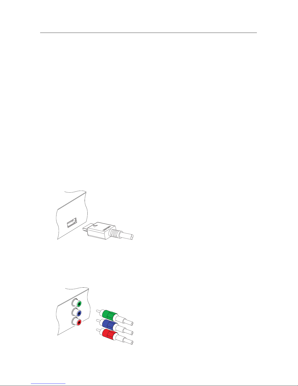
To use the HDMI connector
If you have a high definition television set,
you should use a HDMI cable for best results. Plug one end of the cable into the HDMI
socket on the digital receiver, and the other
end into the matching socket on your television. In this case, you do not have to make
audio connections because the HDMI connector can output stereo audio or Dolby digital
audio.
To use the component video connector
Y
Pb
Pr
You will need to obtain a component video cable (RCA cable) to use the component video
connector. Plug one end of the cables into the
Y (green), Pb (blue) and Pr (red) sockets on
the digital receiver, and the other end into the
matching sockets on your television.
Page 15

2.4 Connecting up your digital receiver 11
To use the RGB video connector
You will need to obtain a RGB cable (15 pin
D-sub cable) to use the RGB connector. Plug
one end of the cable into the RGB socket on
the digital receiver, and the other end into the
matching socket on your television.
To use the composite video connector
NOTE
You cannot view high definition video with
the composite video connector.
You will need to obtain a composite video
cable (RCA cable) to use the composite video
connector. Plug one end of the cable into the
VIDEO (yellow) socket on the digital receiver,
and the other end into the matching socket
on your television.
To connect the audio connectors
You will need to obtain an audio cable (RCA
cable) to connect the audio connectors. Plug
one end of the cable into the AUDIO L (white)
and AUDIO R (red) sockets on the digital receiver, and the other end into the matching
sockets on your television or audio system.
Page 16

12 Setup
2.5 Switching on for the first time
Now that you have your digital receiver connected, you should
plug it in to a mains socket. Ensure that your television set is
turned on, so that you will be able to see the display from the
digital receiver.
2.5.1 Inserting batteries in the remote control
To insert the batteries, open the battery compartment by removing the lid, and then insert the batteries observing the polarity,
which is marked on the base of the battery compartment.
If the digital receiver no longer reacts properly to remote control commands, the batteries may be flat. Be sure to remove
used batteries. The manufacturer accepts no liability for the
damage resulting from leaking batteries.
NOTE
Batteries, including those which contain no heavy metals, may
not be disposed of with household waste. Please dispose of
used batteries in an environmentally sound manner. Find out
about the legal regulations which apply in your area.
2.5.2 Powering on and checking picture
Now, press the button in top left corner on the remote
control.
If you do not see a picture, try pressing the
V.Format button on
the remote control. If after several tries you still get no picture,
check that the television is set to the correct input.
If the picture is good, you can skip to§4.1 to search for the
available television and radio services. Otherwise, you may
need to temporarily connect the composite video connector
(VIDEO) to your television set so that you can see the on-screen
menus in order to configure the video settings.
Page 17

13
Chapter 3
Preference Settings
3.1 Language settings
You can select the language in
which the menu would be displayed. In addition to that, you
can select which language of audio track and of subtitle track
should be output.
Select the System Setting>Language Setting menu. You should
see a screen like the left figure.
Menu language
The digital receiver supports many menu languages: Dutch,
English, German, French, Italian, Russian, Turkish and so forth.
Set the Menu Language option to your desired language. Once
you select a language, the menu will be immediately displayed
in the selected language.
Page 18

14 Preference Settings
Subtitle language
Set the 1st Subtitle Language option and the 2nd Subtitle Language option to your desired languages. When you watch a
programme, if the programme has a subtitle track of the language that is designated for the 1st Subtitle Language, it will be
displayed. If the first language is not available but the second
language is available, the subtitle of the second language will
be displayed. If there is not any available language, no subtitle
will be displayed.
Apart from this setting, you can select a subtitle track with the
button. See § 5.2.5 for detailed description.
Audio language
Set the 1st Audio Language option and the 2nd Audio Language option to your desired languages. When you watch a
programme, if the programme has an audio track of the language that is designated for the 1st Audio Language, it will
be output. If the first language is not available but the second
language is available, the audio of the second language will be
output.
Apart from this setting, you can select an audio track with the
button. See § 5.2.4 for detailed description.
Page 19

3.2 Video and audio settings 15
3.2 Video and audio settings
You have to configure the video
and audio settings appropriately
to your television set and other
appliances.
Select the System Setting
>
A/V Output Setting menu. You
should see a screen like the left
figure.
3.2.1 Television aspect ratio
If you have a wide-screen television, set the TV Aspect Ratio
option to 16:9.
Otherwise, if you have a normal-screen television, set the TV
Aspect Ratio option to 4:3.
You cannot fully enjoy wide-screen programmes with your
normal-screen television as the above figures show. The left
figure shows a normal picture displayed in the normal screen.
To watch wide-screen programmes in the shape like the centre
figure, set the 16:9 Display Format option to Letter Box. Wide-
screen pictures then will be reduced to fit to the width of the
normal screen. Otherwise, to watch them in the shape like the
right figure, set it to Center extract. Wide-screen pictures then
will be cut out on the left and right sides equally to fit to the
width of the normal screen.
Page 20

16 Preference Settings
3.2.2 High definition television
The digital receiver supports various video resolutions from
576 to 1080. In general a resolution of 720 or more is considered
high definition. The higher the resolution is, the better quality
you can enjoy. However, if your television set does not support high definition, you cannot enjoy high definition quality
picture.
Set the Video Format option as you desire. If you set this
option to 576P, the digital receiver will present even high
definition programmes in resolution of 576. On the contrary,
if you set it to 1080I, the digital receiver will present even
standard definition programmes in resolution of 1080. It is
recommended to set it to Auto if you have a high definition
television. With that setting the digital receiver will present a
programme as it is without any resolution conversion. While
watching television you can change the resolution with the
V.Format
button. Whenever you press it, the video resolution is
changed in turn.
YPbPr
RGB
If you have the digital receiver linked to your television
via the component video connectors (Y, Pb and Pr), you
have to toggle the video output selection switch on the
back panel to the YPbPr position. Otherwise if you have
connected it to your monitor via the RGB connector, you
have to toggle the switch to the RGB position. And if
you have connected it to your television via the HDMI
connector, the digital receiver will output video in the
colour model indicated by the switch via that connector.
NOTE
You can enjoy only standard definition video with the following
connectors:
• Composite video connector (VIDEO)
Page 21

3.3 Local time setting 17
3.2.3 Sound mode
Basically, there are two audio sources as you can find two audio
sockets on the back panel of the digital receiver. You can enjoy
only one source or both of them in either stereo or mono. Set
the Sound Mode option as you desire.
Apart from this setting, you can change the sound mode with
the button. See § 5.2.4 for detailed description.
The digital receiver can output two types of digital audio signals via the S/PDIF connector. One is an encoded signal, and
the other is a decoded signal. If your digital audio system does
not have a Dolby Digital decoder, you have to set the Dolby
Digital option to PCM. Otherwise, set it to Bitstream.
3.3 Local time setting
You should set your local time for timer events.
Select the System Setting>Time
Setting menu. You should see a
screen like the left figure.
You can set the clock manually
or use the time signal, Greenwich Mean Time (GMT), carried
as part of the digital television
broadcast.
To use Greenwich Mean Time,
take the following steps:
1.
Set the Mode option to Auto; then the Time Offset option
becomes enabled.
2.
Set the Time Offset option to the time difference between
your time zone and GMT referring to Table 3.1.
3.
Make sure that your local time is correctly displayed on
the Local Time option.
Page 22

18 Preference Settings
Table 3.1: Time offset table
Time offset City
GMT − 12:00 Eniwetok, Kwajalein
GMT − 11:00 Midway Island, Samoa
GMT − 10:00 Hawaii
GMT − 09:00 Alaska
GMT − 08:00 Pacific Time US, Canada
GMT − 07:00 Mountain Time US, Canada
GMT − 06:00 Central Time US, Canada, Mexico City
GMT − 05:00 Eastern Time US, Canada, Bogota, Lima
GMT − 04:00 Atlantic Time Canada, La Paz
GMT − 03:30 Newfoundland
GMT − 03:00 Brazil, Georgetown, Buenos Aries
GMT − 02:00 Mid-Atlantic
GMT − 01:00 Azores, Cape Verde Islands
GMT London, Lisbon, Casablanca
GMT + 1:00 Paris, Brussels, Copenhagen, Madrid
GMT + 2:00 South Africa, Kaliningrad
GMT + 3:00 Baghdad, Riyadh, Moscow, St. Petersburg
GMT + 3:30 Tehran
GMT + 4:00 Abu Dhabi, Muscat, Baku, Tbilisi
GMT + 4:30 Kabul
GMT + 5:00 Ekaterinburg, Islamabad, Karachi, Tashkent
GMT + 5:30 Bombay, Calcutta, Madras, New Delhi
GMT + 6:00 Almaty, Dhaka, Colombo
GMT + 7:00 Bangkok, Hanoi, Jakarta
GMT + 8:00 Beijing, Perth, Singapore, Hong Kong
GMT + 9:00 Tokyo, Seoul, Osaka, Sapporo, Yakutsk
GMT + 9:30 Adelaide, Darwin
GMT + 10:00 Eastern Australia, Guam, Vladivostok
GMT + 11:00 Magadan, Solomon Islands, New Caledonia
GMT + 12:00 Fiji, Auckland, Wellington, Kamchatka
To set the local time yourself, set the Mode option to Manual and
enter your local time to the Local Time option with the numeric
buttons. The time format is day/month/year 24-hour:minute.
If daylight saving time is observed in your state at the moment,
set the Daylight Saving Time option to On.
NOTE
Daylight saving time adds one hour to the time when the option is set to On. When setting the time offset from Greenwich
Page 23

3.4 Parental control 19
Mean Time, make sure that time offset does not include daylight saving time.
3.4 Parental control
In general, television programmes are classified according to
the level of violence, nudity and language of their content.
When you are watching a programme, you can check its programme classification on the information box. For the information box, see § 5.2.3.
You can prevent your children from watching specific programmes by specifying a programme classification.
Select the System Setting
>
Parental Control menu. You
should see a screen like the
left figure, and you will be
asked your Personal Identification Number (PIN). The number
is initially set to ‘0000’.
To block programmes with undesired content for family viewing, set the Censorship option to your desired level among the
following:
No block restricts no prorgramme.
Total block
restricts every programme, even those with no
programme classification.
G
restricts to G or above. G rated programmes are suitable
for all audiences.
PG
restricts to PG or above rated programmes. PG stands
for Parental Guidance, the content of which is mild.
Page 24

20 Preference Settings
M
restricts to M or above rated programmes. M stands for
Mature, the content of which is moderate in impact.
MA
restricts to MA or above rated programmes. MA stands
for Mature Audiance, the content of which is strong.
R
restricts to R rated programmes. R stands for Restricted
to adults aged 18 years or over, the content of which is
very strong.
AV
restricts to AV rated programmes. AV stands for Adult
Viewing, the content of which is deep hardcore.
NOTE
If a programme does not have any programme classification
information, your censorship setting will not take effect.
If anyone is trying to watch a programme that is of or above
the censorship setting, the person has to enter the personal
identification number to override.
To change the number, select the Change PIN Code menu; then
an input box appears. You have to enter a desired number
twice for confirmation.
You can also restrict uses of some menus. Selecting the Access
Control menu displays a list of menus that you can lock. If the
Time Setting item is set to Locked, you have to enter the per-
sonal identification number when accessing the Time Setting
menu. If you enter a wrong number, you cannot use the menu.
To release a shut item, set it to Unlocked.
3.5 Adjusting the on-screen display
You can adjust the transparency level of the on-screen display.
Select the System Setting menu and set the OSD Transparency
option as you desire. Its available range is from 0 to 50 percent.
You can adjust the display time of the information box. For
the information box, see§5.2.3. To adjust its display time,
select the System Setting menu and set the Info Box Display
Page 25

3.5 Adjusting the on-screen display 21
Time option as you desire. Its available range is from 1 to 30
seconds. If you set this option to No Info Box, the information
box will not be displayed when you switch services. However,
pressing the button will display the information box. If you
set this option to Never Hide, the information box will always
be displayed.
In addition, you can raise or lower the position of the information box. Select the System Setting menu and set the Info Box
Position option as you desire. Its available range is from−10
to+3 lines. The more high you set the option, the more low
the information box will be positioned.
Page 26

22 Service Search
Chapter 4
Service Search
After connecting up the digital receiver, you will need to perform a service search.
4.1 Searching broadcasting services
To perform service search, select
the Installation>Service Search
menu. You should see a screen
like the left figure.
If you have an antenna booster,
you should set the Antenna Sup-
ply 5V option to On to supply
power to it.
You should set the Search Mode option to Auto for the first
time after connecting up the digital receiver; then the digital
receiver will search for all available services.
You may choose to only search for services of a specific transponder because more than one service are provided via each
Page 27

4.2 Resetting to factory settings 23
transponder. To do that, set the Search Mode option to Manual,
and then at the Channel option select your desired transponder.
The number ranges from 6 to 12 in VHF and 28 to 69 in UHF.
To start service search, select the Start Search item; then a list
box appears, in which found services will be listed. When it
has completed, press the
OK
button to save found services.
To stop at any time or to exit without saving, press the
EXIT
button.
4.2 Resetting to factory settings
The digital receiver maintains the following data:
• Services list
• Favourite list
• Timer list
• Preference settings
You can reset all data of the digital receiver. To do that, select
the Installation>Factory Setting menu, and then you are asked
for confirmation. If you select Yes, service entries, favourite
entries and timer events will all be deleted, and preference
options will be reset to the manufacturer’s factory settings.
Page 28

24 Daily Usage
Chapter 5
Daily Usage
5.1 Volume control
Use the
V−
and
V+
buttons to alter the volume to a comfortable level. You may need to adjust the volume on your
television set too. To temporarily switch off the sound, press
the button. Press it again to restore the sound to previous
level.
5.2 Watching television
To change services, press the
P+
or
P−
button. Pressing the
button switches to the previously viewed service. In addition, you can switch to your desired service by entering its
service number with the numeric buttons. You can also select a
service to watch in the services list.
5.2.1 The services list
To view the services list, press the
OK button.
Page 29

5.2 Watching television 25
On the services list, you can see
the service information:
• Service number and name
• Transponder information
To select a desired service, put the highlight bar on its entry
with the
P+
or
P−
button and press the
OK
button; then it
will be presented.
Pressing the
V−
or
V+
button skips over 10 entries up or down.
Entering a service number with the numeric buttons puts the
highlight bar on its entry.
You can switch between the television services list and the
radio services list by pressing the button.
To delete the highlighted service, press the
F1
button; then
you are asked for confirmation. If you select Yes, it will be
deleted. If you want to restore it as before, you have to perform
service search again. See § 4.1 for service search.
Pressing the
F4
button displays the additional options, with
which you can do the following:
•
By setting the Show Provider option to On, you can view
service entries by groups of broadcasters.
•
To change the name of the highlighted service, select the
Rename option; then the on-screen keyboard appears,
with which you can enter a new name. See§6.2 for how
to use the on-screen keyboard.
•
You can prevent other family members from watching the
highlighted service by setting the Lock option to Locked.
Page 30

26 Daily Usage
You have to enter your personal identification number to
watch or unlock it.
•
To add the highlighted service into a favourite group,
select the Add to Fav option; then the favourite groups
will be displayed. Put the highlight bar on a desired
group and press the
OK button.
5.2.2 The favourite services list
You can select a service to watch on a favourite list as well as
on the services list.
To display the favourite lists,
press the
FAV
button. You
should see a screen like the left
figure. As you move the highlight bar up or down on the
favourite group list at the left
box, favourite services belonging to the highlighted group are
listed on the right box.
For how to edit the favourite lists, refer to § 6.1.
To select a favourite service, put the hightlight bar on a desired
group and press the
V+
button; a highlight bar appears on its
favourite services list. Once you select a desired service with
the
OK
button, it will be presented. Otherwise, to select other
group, press the
V− button.
After you have selected a favourite service, if you then switch
to another service using the
P+
or
P−
button, it will be also
another favourite service of the selected group. The digital
receiver will remind you what group you have selected by
displaying its name at the top right of the screen whenever you
switch services. If you wish to get out of the current group,
select the All services group on the favourite group list.
Page 31

5.2 Watching television 27
Besides that, you can add or delete a favourite group or service.
To add a service you are watching currently into a favourite
group, put the highlight bar on a desired group and press the
F3
button. To create a new group, press the
F2
button; then
the on-screen keyboard appears. Enter your desired name and
save it. See§6.2 for how to use the on-screen keyboard. To
delete a group or a service, press the
F4 button; then you get
asked for confirmation. If you select Yes, it will be deleted.
5.2.3 Viewing programme information
Pressing the button displays the information box, on which
you can see all of the following:
• Service number and name
• Signal level and quality
• Programme name
• Programme classification symbol
• Programme summary
• Broadcasting time
• Current time
In addition, you might see the following symbols:
•
Subtitle symbol ( ) if subtitle tracks are provided on the
current programme.
•
Teletext symbol ( ) if teletext pages are provided on the
current service.
•
Multifeed symbol ( ) if the current programme is pro-
vided as a multifeed programme. To use this feature,
refer to § ??.
If the electronic programme guide is provided on the current
service, you can see the information about the current and next
Page 32

28 Daily Usage
programmes with the
V−
or
V+
button. To adjust the sound
volume in this case, hold down the
V−
or
V+
button until the
sound bar appears and reaches your desired level.
Pressing the button once more displays detailed information
about the current programme. To hide the information box,
press the
EXIT button.
5.2.4 Selecting audio tracks
Some programmes are provided with audio tacks in one or
more languages. Pressing the button displays available audio tracks. Once you select an audio track, it will be sounded.
In addition, you can enjoy audio tracks in four sound modes:
Stereo, Mono, Left or Right. However, if a multifeed programme is provided at the moment, video tracks will be displayed. In this case, you have to press the button once more
to select an audio track.
5.2.5 Selecting subtitle tracks
Some programmes are provided with subtitle tracks in one or
more languages. If the current programme provides subtitle
tracks, the subtitle symbol ( ) will be marked on the information box. Pressing the button displays available subtitle
tracks. Once you select a subtitle track, it will be displayed.
5.2.6 Viewing teletext
On some services, such information as weather reports, news
or stock quotations is provided by means of teletext. If the
current service provides teletext, the teletext symbol ( ) will
be displayed on the information box. Press the button to
view teletext pages.
Select a desired page to view by entering its page number with
the numeric buttons. You can zoom into a teletext page with
the
F3
button, and adjust its transparency level with the
F4
button. To hide the teletext screen, press the
EXIT button.
Page 33

5.3 Viewing electronic programme guide 29
5.3 Viewing electronic programme guide
The Electronic Programme Guide shows the current and scheduled programmes that are or will be available on each service
with a short summary for each programme.
Pressing the
GUIDE
button displays the electronic programme
guide, on which you can see the
following:
• Scheduled programmes
• programme summary
• Broadcasting date
• Broadcasting time
To see detailed information of a desired programme, put the
highlight bar on your choice with the
P+
or
P−
button and
press the button. To switch to another service, press the
V−
or
V+
button. You can travel over previous days with the
F2
button, and can travel over next days with the
F3 button.
To see the programme guide for radio broadcasts, press the
button. To switch it back, press the button again.
Pressing the
F1
button displays the programme guide in the
form of a spreadsheet. To switch it back, press the
F1
button
again.
NOTE
The provider of each service probably only transmits information about the current and next programmes. However,
a full week programme guide can be obtained with a subscription from a provider such as IceTV in Australia
http:
//www.icetv.com.au
. This lets you schedule recordings by
simply clicking on the name of the programme.
Page 34

30 Daily Usage
For instructions on setting up IceTV, please visit
http://www.
icetv.com.au/topfield.
You can make a timer event on the electronic programme guide
as follows:
1. Select a service you want.
2. Press the
GUIDE button to display its programme guide.
3.
Select a programme you want with the
OK
button, then
P
is marked up on the entry. At the same time, a timer
event with the selected programme will be made in the
timer list. Refer the timer list to § 5.4.
4.
To remove the marking, press the
OK
button once again.
5.4 Making timer events
You can make your desired services to be presented at a specific
time. Even if the digital receiver is in standby mode, it will
switch into operation mode at the specifiged time. However,
if you press any button on the remote control or on the front
panel even just one time, the digital receiver will not switch
into standby mode.
To input a timer recording, select
the Timer Setting menu; then the
timer list will be displayed.
To add a new timer event, press
the
F1
button, and a box like
the left figure appears. Take the
following steps:
Page 35

5.4 Making timer events 31
1.
If you want a radio programme, set the Type option to
Radio; otherwise, set it to TV.
2.
Set the Service option to the service which provides the
programme you want. Pressing the
OK
button on this
option displays a services list, from which you can select
your desired service.
3. There are five timer modes:
One Time means literally ‘one time’.
Every Day means literally ‘every day’.
Every Weekend
means ‘Saturday and Sunday every
week’.
Weekly means ‘one day every week’.
Every Weekday
means ‘from Monday to Friday every
week’.
If your favourite programme is broadcasted at weekends
and you wish to watch every episode of the programme,
set the Mode option to Every Weekend.
4.
Set the Date option to a desired date, on which the digital
receiver will turn on. The date format is day/month/year-
day of the week.
Set the Wakeup Time option to a desired time, at which
the digital receiver will turn on. The time format is
hour:minute.
5.
Set the Duration option to a desired time, in which the
digital receiver will turn off.
6.
To set a timer event with the above settings, select the OK
option; otherwise, it will not be saved and will not occur.
To delete a timer event, put the highlight bar on the entry you
want to remove and press the
F2
button; then you are asked
for confirmation. If you select Yes, it will be deleted.
Page 36

32 Listing Services
Chapter 6
Listing Services
6.1 Editing the favourite list
You can make your own favourite services list. In fact, you can
define multiple favourite services lists, each being a ‘group’ of
chosen services.
Select the Organizing Favorites
menu. You should see a screen
like the left figure.
There are three columns:
• Group list (left)
• Favourite list (centre)
• Services list (right)
The services list contains all available services, whereas the
favourite list contains only chosen services that have been
added to the highlighted group. As you move the highlight
bar up or down on the group list, favourite services belonging
to the highlighted group get shown in the favourite list.
Page 37

6.1 Editing the favourite list 33
You can add up to 30 groups. To add a group, select the NEW
option in the group list; then the on-screen keyboard appears.
See § 6.2 for how to use the on-screen keyboard.
To rename a group, put the highlight bar on the group entry you
want and press the
F2
button; then the on-screen keyboard
appears. See § 6.2 for how to use the on-screen keyboard.
To delete a group, put the highlight bar on the group entry you
want and press the
F3
button; then a message box appears
asking you for confirmation. If you select Yes, it will be deleted.
You can add a favourite service to a group by taking the following steps:
1.
Put the highlight bar on a desired group entry in the
group list and press the
OK
button to select it. The high-
light bar then moves to the services list.
2.
To add a service to the selected group, put the highlight
bar on a desired service entry and press the
OK
button.
The selected service entry gets added to the favourite list.
Repeat this step to add more entries.
3.
Press the
F1
button and the highlight bar get moved to
the favourite list. You can delete a favourite entry with
the
OK button.
4.
To select another group, press the
F1
button again. By
pressing the
F1
button, the highlight bar gets moved to
each column.
To add radio services, press the button; then radio service
entries get listed in the services list. To recall the television
services list after adding radio services, press the button
again.
With your favourite services list, you can select your favourite
services more easily. Refer to § 5.2.2 for detailed description.
Page 38

34 Listing Services
6.2 How to use on-screen keyboard
You can move the highlight key
horizontally with the
V−
and
V+
buttons and vertically with
the
P+
and
P−
buttons. Press-
ing the
OK
button on a key en-
ters its letter in the input line. To
type a space, select the Space
key. To type lower case letters or
numerals, select the Other key.
To delete a letter, put the cursor to the right of the desired letter
on the input line and then select the Del key. You must select
the Save key to complete naming; otherwise, if you press the
EXIT button, it will not be named.
6.3 Transferring receiver data
The digital receiver retains the following data:
• Services list
• Favourite lists
• Preference settings
It is possible to transfer the receiver data from the digital receiver to another same digital receiver by connecting them with
a RS-232 cable. To have the receiver data transferred, perform
the following steps:
Page 39

6.3 Transferring receiver data 35
1.
Plug one end of a RS-232 cable (9 pin Dsub cable) into the RS-232 port on the digital receiver, and the other end into the
matching port on the other digital receiver.
2. Turn on the source digital receiver.
3.
Select the Installation>Transfer Firmware
>
Transfer Data to Other IRD menu, then
you get asked for confirmation; select Yes.
4.
To start the data transfer, turn on the target
digital receiver.
5.
A progress bar appears showing the
progress of the data transfer.
6.
Restart the target digital receiver when the
data transfer is complete.
Page 40

36 Firmware Update
Chapter 7
Firmware Update
The digital receiver has a stable and convenient firmware to
use. However, a new firmware may be released to improve
the digital receiver. You can get the latest firmware and an
update utility which runs on most versions of Windows from
the Topfield website, http://www.i-topfield.com.
7.1 Checking the firmware information
You have to check the firmware
information of your digital receiver before downloading a
new firmware. Select the Infor-
mation>IRD Status menu. You
should see a screen like the left
figure.
Remember the System ID, and download a firmware with the
same system identification.
Page 41

7.1 Checking the firmware information 37
NOTE
You can only update with firmwares of which system identification is identical to that of yours. Otherwise you will fail in
firmware update.
Page 42

38 Firmware Update
7.2 From your computer via RS-232 port
It is possible to transfer a new firmware to the digital receiver
from your computer by connecting them with a RS-232 cable.
You need TFD-Down, a firmware transfer utility for this, which
is available from the website, http://www.i-topfield.com.
To update the firmware with this method, perform the following steps:
1.
Download a new firmware applicable to
your digital receiver from the Topfield
website.
2. Turn off the digital receiver.
3.
Plug one end of a RS-232 cable (9 pin Dsub cable) into the RS-232 port on the digital receiver, and the other end into the
matching port on your computer.
4. Run TFD-Down.
The instructions on how to use TFD-Down are as follows:
1.
Press the Find button to select the new
firmware file.
2.
Press the download button, and then turn
on the digital receiver to start the file trans-
fer.
3. A countdown will be displayed on screen
4.
Restart the digital receiver when the file
transfer is complete.
Page 43

7.3 From another digital receiver via RS-232 port 39
7.3 From another digital receiver via RS-232 port
It is possible to transfer the firmware from the digital receiver
to another same digital receiver by connecting them with a RS232 cable. To update the firmware with this method, perform
the following steps:
1. Turn off the target digital receiver.
2.
Plug one end of a RS-232 cable (9 pin Dsub cable) into the RS-232 port on the digital receiver, and the other end into the
matching port on the other digital receiver.
3.
Turn on the source digital receiver if not
already on.
4.
Select the Installation>Transfer Firmware
>
Transfer Firmware to Other IRD menu,
then you get asked for confirmation; select
Yes.
5.
Turn on the target digital receiver to start
the firmware transfer.
6.
A progress bar appears showing the
progress of the firmware transfer.
7.
Restart the target digital receiver when the
firmware transfer is complete.
Page 44

40 INDEX
Index
16:9, 15
16:9 Display Format, 15
1st Audio Language, 14
1st Subtitle Language, 14
2nd Audio Language, 14
2nd Subtitle Language, 14
4:3, 15
A/V Output Setting, 15
Access Control, 20
Add to Fav, 26
ANT, 8
ANT, 9
Antenna Supply 5V, 22
AUDIO L, 11
AUDIO L/R, 8
AUDIO R, 11
Auto, 22
AV, 20
Button, 4
Censorship, 19
Center extract, 15
Change PIN Code, 20
Channel, 23
Date, 31
Daylight Saving Time, 18
Dolby Digital, 17
download, 38
Duration, 31
DVB, 1
Electronic Programme Guide, 29
Every Day, 31
Every Weekday, 31
Every Weekend, 31
Factory Setting, 23
Find, 38
G, 19
HD MODE, 8
HDMI, 8
HDMI, 10, 16
high definition, 16
Info Box Display Time, 21
Info Box Position, 21
information box, 27
IRD Status, 36
keyboard, 34
Language Setting, 13
Letter Box, 15
Local Time, 17, 18
Lock, 25
M, 20
MA, 20
Manual, 23
Page 45

41
Menu Language, 13
Mode, 17, 18, 31
mono, 17
NEW, 33
No block, 19
normal-screen television, 15
One Time, 31
Organizing Favorites, 32
OSD Transparency, 20
Parental Control, 19
PG, 19
PIN, 19
R, 20
Radio, 31
Rename, 25
RF LOOP OUT, 8
RF LOOP OUT, 9
RGB, 8
RGB, 11, 16
RS-232, 9
RS-232, 35, 38, 39
S-VIDEO, 8
S/PDIF, 17
S/PDIF COAXIAL, 8
S/PDIF OPTICAL, 9
Search Mode, 22, 23
Service, 31
Service Search, 22
services list, 24
Show Provider, 25
Sound Mode, 17
Space, 34
specifications, 7, 9
Start Search, 23
stereo, 17
subtitle, 28
System ID, 36
System Setting, 20, 21
teletext, 28
TFD-Down, 38
time format, 18
Time Offset, 17
Time Setting, 17, 20
timer list, 30
Timer Setting, 30
Total block, 19
Transfer Data to Other IRD, 35
Transfer Firmware to Other IRD, 39
transponder, 1
TV, 31
TV Aspect Ratio, 15
Type, 31
VIDEO, 8
VIDEO, 10, 11, 16
Video Format, 16
Wakeup Time, 31
Weekly, 31
wide-screen television, 15
Y/Pb/Pr, 8
YPbPr, 16
Page 46

Page 47

Page 48

Correct disposal of this product
This marking shown on the product or its literature indicates that it should
not be disposed with other household wastes at the end of its working life. To
prevent possible harm to the environment or human health from uncontrolled
waste disposal, please separate this from other types of wastes and recycle it
responsibly to promote the sustainable reuse of material resources.
Household users should contact either the retailer where they purchased this
product or their local government office for details of where and how they
can dispose this product for environmentally safe recycling.
Business users should contact their supplier and check the terms and condi-
tions of the purchase contract. This product should not be mixed with other
commercial wastes for disposal.
Topfield continues to improve the digital receiver which this guide explains. So some expla-
nations and illustrations in this guide could be different from the actual digital receiver.
Copyright © 2007, Topfield Co., Ltd. Australian version
http://www.i-topfield.com 110T-43142-219-1
 Loading...