

Page 1
TOPFIELD
TF6000F
User Manual
Digital Satellite Receiver
Free To Air
Page 2

ii CONTENTS
Contents
Contents ii
1 Overview 1
1.1 Introduction . . . . . . . . . . . . . . . . . . . . . . . . . . . . 1
1.2 Controlling The Digital Receiver . . . . . . . . . . . . . . . . . 2
1.2.1 Front Panel . . . . . . . . . . . . . . . . . . . . . . . . 2
1.2.2 Remote Control . . . . . . . . . . . . . . . . . . . . . . 3
2 Installation 5
2.1 Packing Contents . . . . . . . . . . . . . . . . . . . . . . . . . 5
2.2 Safety Precautions . . . . . . . . . . . . . . . . . . . . . . . . . 5
2.3 The Connection Panel . . . . . . . . . . . . . . . . . . . . . . . 7
2.4 Connecting The Digital Receiver . . . . . . . . . . . . . . . . . 7
2.4.1 Connecting to The Satellite Antenna . . . . . . . . . . 7
2.4.2 Connecting to The TV by RCA Cable . . . . . . . . . . 8
2.4.3 Connecting to The TV by RF Cable . . . . . . . . . . . 8
2.5 Inserting Batteries in The Remote Control . . . . . . . . . . . 9
2.6 Station Settings . . . . . . . . . . . . . . . . . . . . . . . . . . 9
2.6.1 LNB Setting . . . . . . . . . . . . . . . . . . . . . . . . 10
Page 3

iii
2.6.2 Service Search . . . . . . . . . . . . . . . . . . . . . . . 12
2.6.3 Motorized DiSEqC 1.2 . . . . . . . . . . . . . . . . . . 14
2.6.4 USALS Setting . . . . . . . . . . . . . . . . . . . . . . . 15
2.6.5 Editing The Transponder List . . . . . . . . . . . . . . 17
2.6.6 Factory Setting . . . . . . . . . . . . . . . . . . . . . . 19
2.6.7 System Recovery . . . . . . . . . . . . . . . . . . . . . 19
3 Preference Settings 20
3.1 Time Setting . . . . . . . . . . . . . . . . . . . . . . . . . . . . 20
3.2 Timer Setting . . . . . . . . . . . . . . . . . . . . . . . . . . . . 21
3.3 Access Restriction . . . . . . . . . . . . . . . . . . . . . . . . . 23
3.4 Language Setting . . . . . . . . . . . . . . . . . . . . . . . . . 24
3.5 Audio and Video Setting . . . . . . . . . . . . . . . . . . . . . 25
3.6 Menu Display Transparency . . . . . . . . . . . . . . . . . . . 26
3.7 Display Time of The Information Box . . . . . . . . . . . . . . 26
3.8 Position of The Information Box . . . . . . . . . . . . . . . . . 26
4 Listing Services 28
4.1 Editing The Services List . . . . . . . . . . . . . . . . . . . . . 28
4.2 Editing The Favorites List . . . . . . . . . . . . . . . . . . . . 30
5 Daily Usage 31
5.1 Browsing Services . . . . . . . . . . . . . . . . . . . . . . . . . 31
5.2 Information Box . . . . . . . . . . . . . . . . . . . . . . . . . . 32
5.3 Electronic Program Guide . . . . . . . . . . . . . . . . . . . . 33
5.4 Viweing Subtitle . . . . . . . . . . . . . . . . . . . . . . . . . . 34
5.5 Viewing Teletext . . . . . . . . . . . . . . . . . . . . . . . . . . 34
5.6 Selecting Sound Track . . . . . . . . . . . . . . . . . . . . . . . 35
5.7 Selecting Multifeed . . . . . . . . . . . . . . . . . . . . . . . . 35
Page 4

iv CONTENTS
6 Firmware Update and Data Transfer 36
6.1 Firmware Update . . . . . . . . . . . . . . . . . . . . . . . . . 37
6.1.1 From The Satellite . . . . . . . . . . . . . . . . . . . . . 37
6.1.2 From a Personal Computer via RS232 Port . . . . . . . 37
6.1.3 From another Digital Receiver via RS232 Port . . . . . 38
6.2 Data Transfer . . . . . . . . . . . . . . . . . . . . . . . . . . . . 39
A Information 40
A.1 Operational Functions and Features . . . . . . . . . . . . . . . 40
A.2 Technical Specification . . . . . . . . . . . . . . . . . . . . . . 41
Index 43
Page 5

1.1 Introduction
The TF6000F digital receiver is fully compliant with the international digital video broadcasting standard, and can play
digital satellite services. To operate it, you need a satellite antenna, which must be installed and directed at the required
satellite.
Unlike analogue broadcasting, digital television and radio services are not all assigned their own frequencies; instead, several television and radio are transmitted by a single transponder.
To help you with the choice and settings for satellite services,
a selection of television and radio services have already been
programmed for you. You can do service search so that all the
satellite services that have since gone on air are available to
you. Of course, you can easily program new services yourself.
You can find the current transponder information on teletext
from various broadcasters.
The TF6000F digital receiver has the features as follows:
1
Chapter 1
Overview
Page 6
2 Overview
CHANNEL
• This digital receiver supports DiSEqC 1.0, DiSEqC 1.1,
DiSEqC 1.2 and USALS (DiSEqC).
• This digtial receiver saves up to 5000 TV and radio ser-
vices.
• You can edit the service list and make your own favorite
service list.
• You can view the program guide
• You can view the information of a TV programme.
• You can update the firmware of the digital receiver to
the latest, which will be provided by Topfield.
Refer to Section A.1 on page 40 for detailed features.
1.2 Controlling The Digital Receiver
You can control the digital receiver with the remote control
and the front panel buttons.
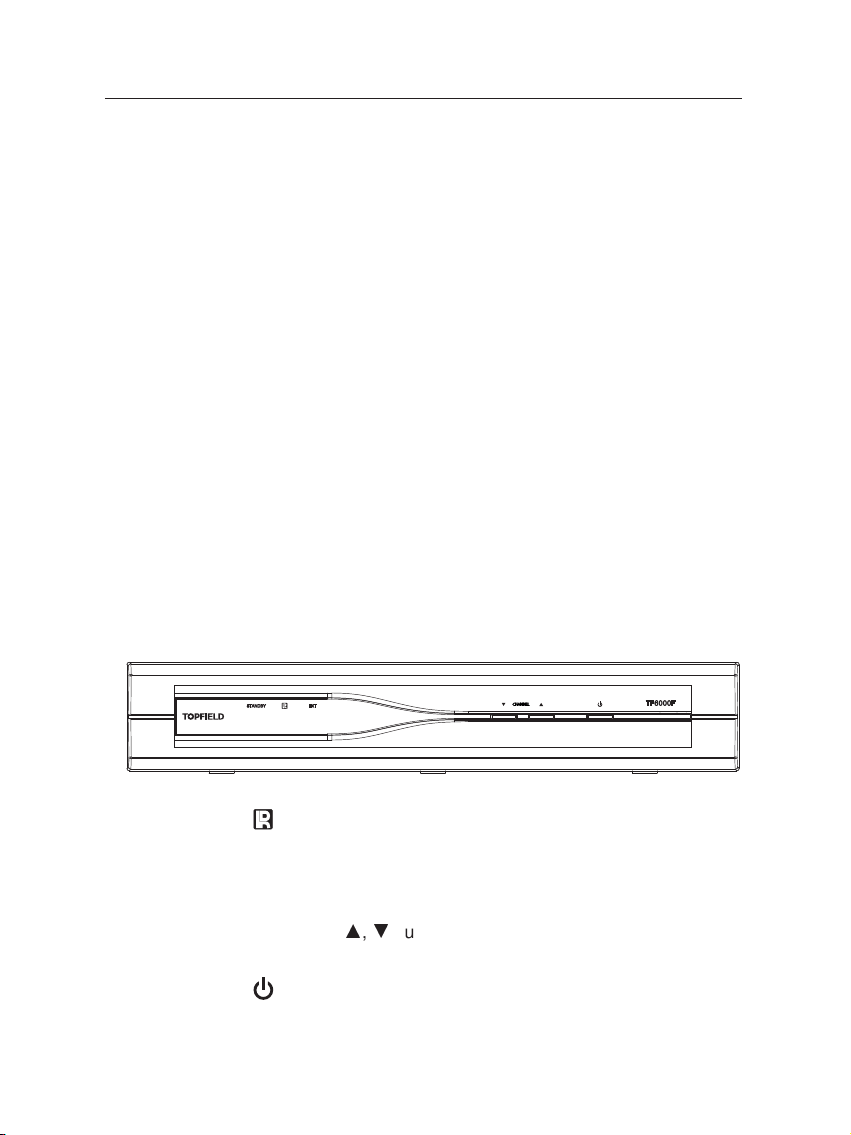
1.2.1 Front Panel
lamp lights up whenever you press a button of the remote
control.
PWR lamp lights up while the digital receiver is in the the
standby mode.
CHANNELa,cbuttons switch services up and down, and
move the cursor up and down in the menus.
button toggles the digital receiver between the operation
mode and the standby mode.
Page 7
1.2 Controlling The Digital Receiver 3
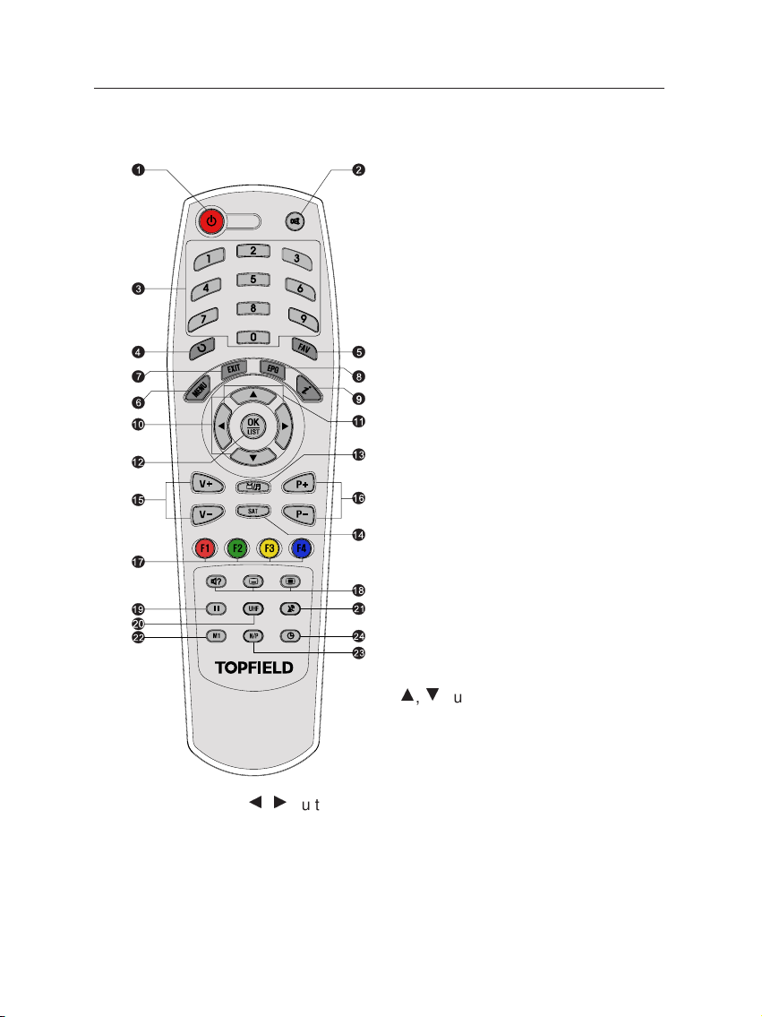
1.2.2 Remote Control
1
Standby button toggles the digital re-
ceiver between operation mode
and standby mode.
2
Mute button mutes the television or
audio appliance.
3
Numeric buttons selects a service to
watch, or enters a parameter
value such as recording time.
4
Recall button makes a return to the
previous service.
5
FAV button displays the favorite ser-
vice list.
6
Menu button displays the menu, or
escapes to a higher level menu
out of a submenu.
7
Exit button escapes from any menu.
8
Guide button displays program
guides, if available.
9
Information button displays the infor-
mation about the programme on
the air.
10
a,c
buttons switch services up and
down, and move the cursor up
and down in the menus.
11
b,d
buttons change the volume, and select and change
individual entries in the menus.
12
OK button displays the service list, and selects an entry in
the menus.
13
TV/Radio button toggles between TVmode and radio mode.
Page 8

4 Overview
14
SAT button displays the satellite list. (available only for the
satellite receiver)
15
V+ and V− buttons change the volume, and select and change
individual entries in the menus.
16
P+ and P− buttons switch services up and down, and move
the cursor up and down in the menus.
17
Function buttons have other functions per menu. Their func-
tions will be guided in the help window on a menu
screen.
18
Sound, Subtitle and Teletext button selects sound track and
mode, enables subtitle display, and enables teletext display, if available.
19
Pause button keeps a picture from the programme on the
air as it is.
20
UHF button displays the RF modulator settings.
21
TV/STB button toggles between digital TV from the digital
receiver and analogue TV from the conventional aerial
broadcasting.
22
M1 button displays the multipicture selection window. (avail-
able only in specific models)
23
N/P button switches the colour encoding method.
24
Sleep button sets the sleep timer. The digital receiver is
turned off to standby mode when a specified time is
elapsed,
Page 9

2.1 Packing Contents
Unpack your receiver and check the following cables and accessories are also included in the package:
• 1 remote control.
• 2 batteries (AAA 1.5 V).
• 1 user manual
5
Chapter 2
Installation
2.2 Safety Precautions
Please read the following safety precautions carefully for your
safety.
• The mains supply must be 90 to 250 volt. Check it before
connecting the digital receiver to the mains supply.
• This digital receiver is designed to receive, record and
play back video and audio signals. Any other use is expressly prohibited.
Page 10

6 Installation
• When setting up the digital receiver, make sure it is in
a horizontal position and that the mains socket is easily
accessible.
• Do not expose the digital receiver to any moisture. The
digital receiver is designed for use in dry rooms. If you
do use it outdoors, please ensure that it is protected from
moisture, such as rain or splashing water. Do not place
any vessels such as vases on the digital receiver. These
may be knocked over and spill fluid on the electrical
components, thus presenting a safety risk.
• Do not place the digital receiver close to heating units or
in direct sunlight, as this will impair cooling. Place the
digital receiver on a hard, level surface. Do not lay any
objects such as magazines on the digital receiver. When
placed in a cabinet, make sure there is a minimum space
of 10 cm around it.
• Thunderstorms are a danger to all electrical devices. Even
if the digital receiver player is switched off, it can be
damaged by a lightning strike to the mains or the antenna. Always disconnect the mains and antenna plugs
during a storm.
• Never open the digital receiver casing under any cir-
cumstances. Warranty claims are excluded for damage
resulting from improper handling.
Page 11
2.3 The Connection Panel 7
RS-232
LNB OUT
LNB IN
R - AUDIO - L
VIDEO
RF OUT
RF IN
X
YZ[
\
^
]
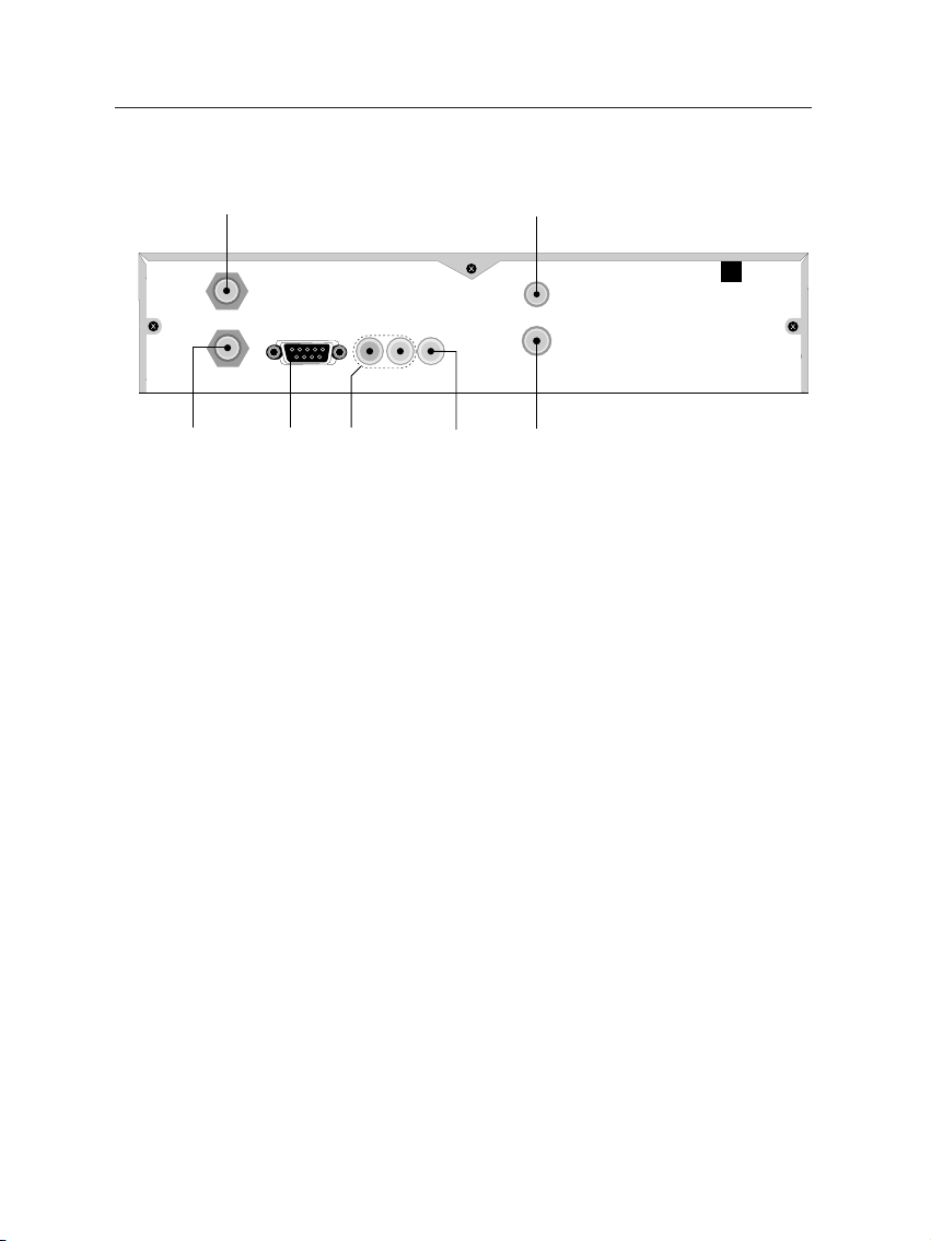
2.3 The Connection Panel
1) LNB IN: Satellite broadcast input socket.
2) LNB OUT: Satellite broadcast output socket.
3) VIDEO: Composite video output socket for television or AV
receiver.
4) R-AUDIO-L: Stereo audio output socket for television or au-
dio appliance.
5) RF IN: Terrestrial broadcast input socket from conventional
aerial antenna.
6) RF OUT: AV output socket for television.
7) RS232: Serial port for firmware update and data transfer
2.4 Connecting The Digital Receiver
There are some ways to install the digital receiver as described
below. Install the digital receiver suitably to your television
and audio appliance. If you have problems with your instal-
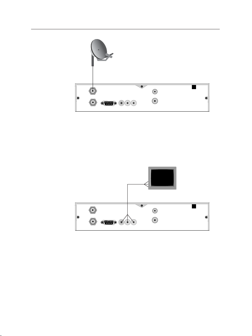
2.4.1 Connecting to The Satellite Antenna
lation or need a help, contact your dealer or service provider.
Connect the satellite antenna cable to the LNB IN socket on the
digital receiver.
Page 12
8 Installation
RS-232
LNB OUT
LNB IN
R - AUDIO - L
VIDEO
RF OUT
RF IN
RS-232
LNB OUT
LNB IN
R - AUDIO - L
VIDEO
RF OUT
RF IN
2.4.2 Connecting to The TV by RCA Cable
Plug a RCA cable into the VIDEO (yellow), L AUDIO (white)
and R AUDIO (red) sockets on the digital receiver and the corresponding input sockets on the television or audio appliance.
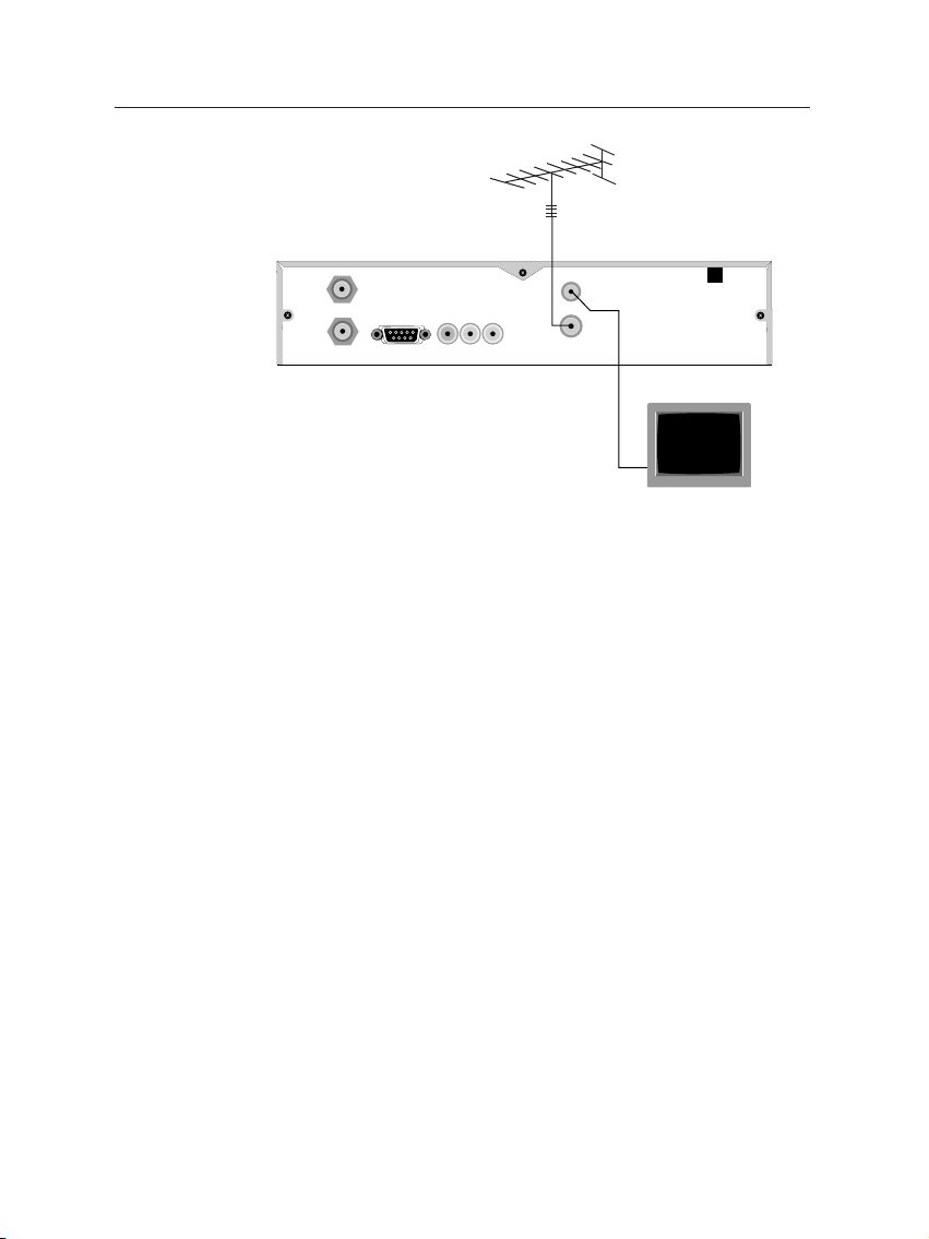
2.4.3 Connecting to The TV by RF Cable
Connect the aerial antenna cable to the RF IN socket on the
digital receiver, and then plug a RF cable into the RF OUT
socket on the digital receiver and the corresponding input socket
on the television.
Page 13
2.5 Inserting Batteries in The Remote Control 9
RS-232
LNB OUT
LNB IN
R - AUDIO - L
VIDEO
RF OUT
RF IN
2.5 Inserting Batteries in The Remote Control
1. Open the battery compartment by removing the lid.
2. Insert the batteries Observe the polarity (marked on the
base of the battery compartment).
3. Close the battery compartment.
2.6 Station Settings
If the digital receiver no longer reacts properly to remote control commands, the batteries may be flat. Be sure to remove
used batteries. The manufacturer accepts no liability for damage resulting from leaking batteries.
Note Batteries, including those which contain no heavy met-
als, may not be disposed of with household waste.
Please dispose of used batteries in an environmentally
sound manner. Find out about the legal regulations
which apply in your area.
This digital receiver can be operated with fixed and motorised
antenna system. You have to configure station settings accord-
Page 14
10 Installation
ing to your antenna system.
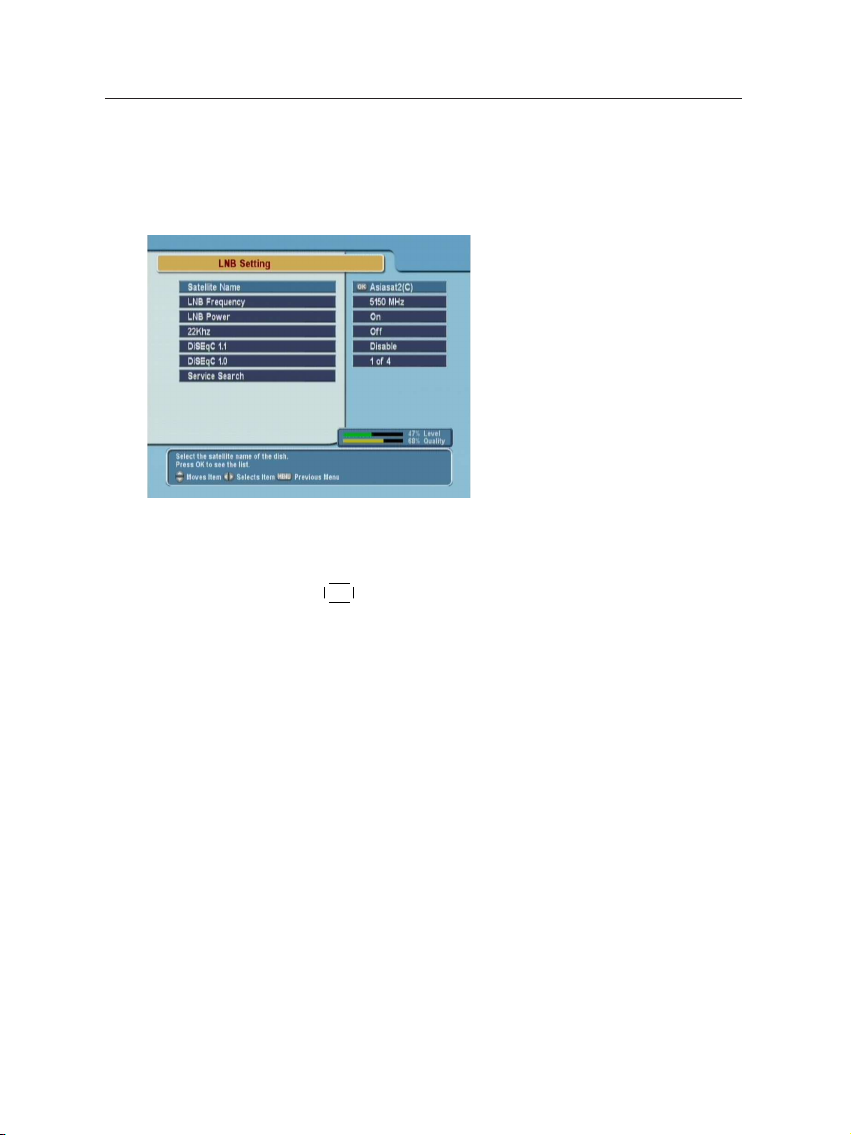
2.6.1 LNB Setting
The LNB (Low Noise Block)
down-converter amplifies the
signal received by the antenna
and lowers the frequency of
the signal. The signal is then
fed from the LNB to the digital
receiver.
To configure the LNB setting, select the Installation > LNB Set-
ting menu.
Satellite Name
Pressing
alphabetical order. Select one of the preprogrammed satellites
that corresponds to the direction of the antenna. If a desired
satellite is not in the list, then select Other.
¤£¡
OK button displays the satellite list, which is listed in
¢
LNB Frequency
LNB Power
22 kHz
Select the local oscillator frequency of the LNB. You can input
the frequency with the numeric buttons.
Set this parameter to on to supply the LNB with power.
If you have a 22 kHz tone switch box and wish to enable it, set
this parameter to on. If the LNB Frequency parameter is set to
Universal LNB, this parameter is not available.
Page 15
2.6 Station Settings 11
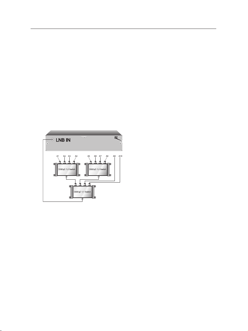
DiSEqC 1.1 and DiSEqC 1.0
This digital receiver is designed to be DiSEqC 1.1 compatible.
This allows multiple antennas to be connected to one digital
receiver at the same time. If you have two or more fixed antennas, then it is recommended to use a DiSEqC 1.1 switch.
If you have an only DiSEqC 1.1 switch, it is possible to connect
up to 4 antennas. Set the DiSEqC 1.0 to Disable and select an
item in DiSEqC1.1. If you use a DiSEqC1.1 switch and DiSEqC
1.0 switches, it is possible to connect up to 16 antennas. Connect the DiSEqC1.1 switch to the digital receiver and connect
the DiSEqC 1.0 switches to the DiSEqC1.1 switch.
Set the DiSEqC 1.1 parameter and DiS-
EqC 1.0 parameter according to the antenna configuration. For example, to
select A7 in the figure, set the DiS-
EqC1.1 parameter to 2 of 4 and the
DiSEqC1.0 parameter to 3 of 4.
Page 16
12 Installation
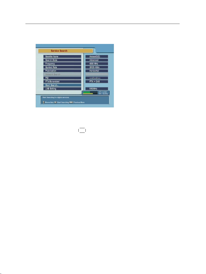
2.6.2 Service Search
To search services, select the
Installation > Service Search
menu.
Satellite Name
Pressing
alphabetical order. Select one of the preprogrammed satellites
that corresponds to the direction of the antenna. If a desired
satellite is not in the list, then select Other.
Search Mode
¤£¡
OK button displays the satellite list, which is listed in
¢
Frequency
The Auto mode uses the information the digital receiver has.
To use the Manual mode, you have to know in advance the frequency, symbol rate and polarization type of the transponder
you want to search. To use the Advanced mode, you have to
know the audio PID, video PID or PCR PID of the transponder you want to search. The SMATV mode is used for special
purposes on the satellite master antenna TV system.
In manual, advanced or SMATV search mode, select or enter
the frequency of the transponder you want to search.
Page 17

2.6 Station Settings 13
Symbol Rate
In manual, advanced or SMATV search mode, select or enter
the symbol rate of the transponder you want to search.
Polarization
In manual or advanced search mode. select the polarization
type of the transponder you want to search.
Network Search
In automatic or manual search mode, if NIT (Network Information Table) is available and this parameter is set to on, the
information of the transponder you want to search will be
found.
PID
PID (Packet Identifier) is a set of numbers that identifies the
transport streams packets from a single data stream. In advanced search mode, enter and save the PIDs of the transponder you want to search.
FTA/Scrambled
Start Search
Select the station class you want to search. FTA (Free To Air)
is free, but CAS (Conditional Access System) is not.
To start the service search, select this menu. To cancel the
search in process, press the
¤£¡
EXIT button.
¢
Page 18
14 Installation
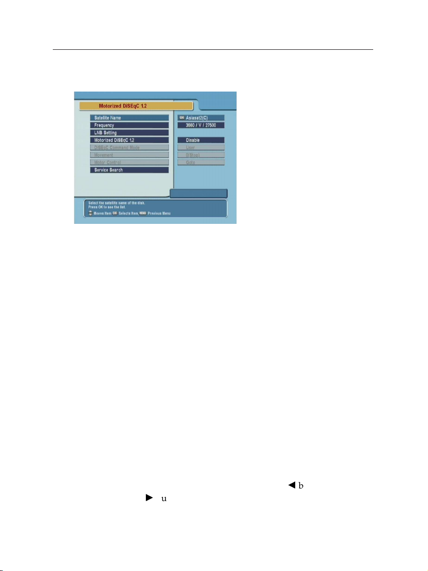
2.6.3 Motorized DiSEqC 1.2
To configure the settings with
DiSEqC 1.2, select the Installation
> Motorized DiSEqC 1.2 menu.
Satellite Name
Select a satellite that will be used to identify a motor position.
Frequency
Select a transponder of which signal is strong.
Motorized DiSEqC 1.2
Set this parameter to enable if you have DiSEqC 1.2 antenna.
DiSEqC Command Mode
To finely tune the position of the antenna for better reception,
select the User mode. To search the position of a satellite manullay, select the Installer mode.
Movement
In the user mode, the antenna is moved by fine tuning. In the
installer mode, the antenna is moved bybbutton (to the east)
anddbutton(to the west).
Page 19

2.6 Station Settings 15
Motor Control
Goto: Move the motor to the stored position of the selected
satellite.
Store: Store the current position of the motor for the selected
satellite.
The followings are available only in the Installer mode.
Recalculate: Recalculate the position of the Stab Rotor motor.
Goto Ref: Go to reference.
Limit E, Limit W: Set the limits of East and West position.
Limit Off: Remove the limitation.
Reset: Reset all the stored position of the motor relative to the
‘0’ position
2.6.4 USALS Setting
USALS is very convenient motorized DiSEqC system that supports DiSEqC 1.3 command and
also can get the satellite position
automatically if you know your
geographical location.
To configure the USALS settings,
select the Installation > USALS
Setting menu.
Motorized DiSEqC 1.3
Set this parameter to enable if you have DiSEqC 1.3 switch.
Satellite Name
Select a satellite that will be used to identify a motor position.
Page 20

16 Installation
Satellite Angle
This parameter represents the longitude of the selected satellite and it can be set automatically in case of selecting a satellite
name. You can use the numeric buttons enter the angle. East
or West will be selected bybanddbuttons.
My Longitude
This parameter represents the longitude of your location. You
can select the angle, East and West byb,dor numeric buttons.
My Latitude
This parameter represents the latitude of your location. You
can select the angle, South or North byb,dor numeric buttons.
Reference Position
This menu makes go to the reference position (φ°).
Move
Frequency
Goto the position
After searching the position you want by Goto the position
item, you can tune the antenna to go to the exact position
by this item.banddbutton moves the antenna to anticlockwise and clockwise respectively.
Select a transponder of which signal is strong.
After setting the Longitude, Latitude and the longitude of the
selected satellite, this menu is used when you want to move
the desired direction (position) of the dish saved before. Its
moving limit is ± 65 °.
Page 21
2.6 Station Settings 17
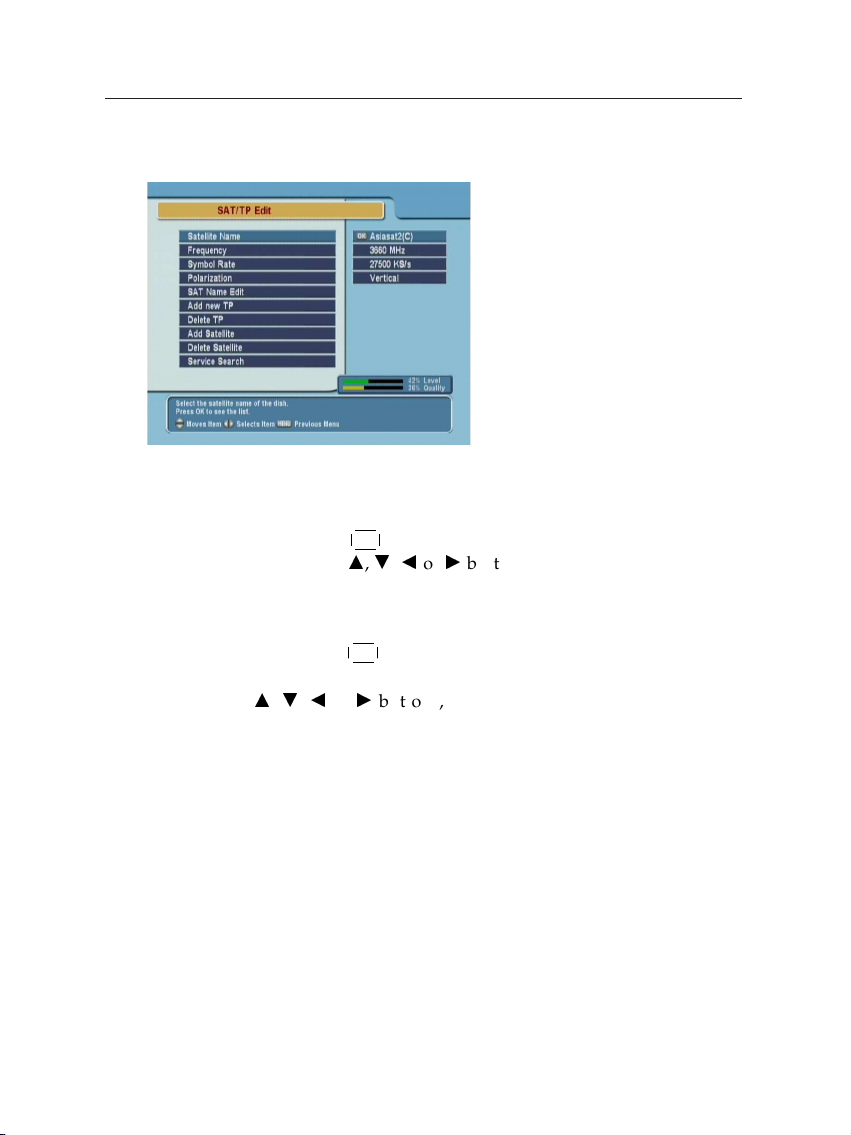
2.6.5 Editing The Transponder List
To edit the transponder list, select the Installation > SAT/TP
Edit menu.
Satellite Name
By pressing
Then,usinga,c,bordbuttons, you can select satellite.
Frequency
By pressing
ders of a satellite and can select a frequency. Or, by pressing
a,c,bord
one by one.
¤£¡
OK button, you can see the listed satellite names.
¢
¤£¡
OK button, you can see the all frequencies of transpon-
¢
buttons, you can select and view a frequency
Symbol Rate
Polarization
You can see the symbol rate of specified satellite on the right
side of the menu.
You can select the polarization from Horizontal and Vertical
modes.
Page 22

18 Installation
SAT Name Edit
You can change the name of the satellite name by this menu.
¤£¡
Press
OK button to display a keyboard. There are several
items such as Other, Save and Space in the keyboard. By selecting Other item, you can see a new alphabet character sets.
The Space item make a space between two characters. And
the Save item is used to confirm the new name of the satellite.
Note You can move the cursor in the keyboard row bybor
Add New TP
In case of new transponder information is added by broadcaster, you can add new TP(transponder) information and enjoy new services. Before adding new TP information, you
should know the frequency, symbol rate and polarization types.
After adding new information, you should confirm the new
information by pressing
Delete TP
¢
or and column byaorc, button.
d
¤£¡
OK button at OK item.
¢
Add Satellite
Delete Satellite
By selecting this item, you can delete the selected TP(Transponder)
information.
Using this menu, you can add new satellite name by keyboard,
then it will be added in the Satellite Name menu.
By selecting this item, you can delete the selected satellite information.
Page 23

2.6 Station Settings 19
Service Search
It is used to go to Service Search menu directly from SAT/TP
Edit menu.
2.6.6 Factory Setting
All the stored data can be reset just like it was manufactured.
To reset all of the settings and lists, select the Installation >
Factory Setting menu. The factory setting has two steps. The
first is to reset the service data and other system configurations except Motorized DiSEqC 1.2 setting. The second is to
reset the parameters of Motorized DiSEqC 1.2.
2.6.7 System Recovery
To restore the preference settings and lists, select the Installation > Factory Setting menu. All the data and system setting
can be stored and restored.
Recover
It recovers all the stored data and system setting. The factory
default setting will be reloaded unless the installer stores the
data and system setting by Store function.
Store
It stores all the data and system setting as current setting. The
stored data and seting will be restored by Recover function. It
is permitted only to the installers. The PIN code is different
from that of users.
Page 24

20 Preference Settings
Chapter 3
Preference Settings
3.1 Time Setting
To set the local time, select the
System Setting > Local Time
Setting menu.
The exact local current time can
be adjusted by using the Mode,
the Local Time and the Time Off-
set submenus.
Mode
By usingb,dyou can select on of the Auto/Manual mode.
The Auto mode updates the time settings automatically by the
GMT received from the broadcast and the Time Offset you
have inserted. The Auto mode is recommended.
Page 25

3.2 Timer Setting 21
Local Time
The Local Time is adjustable only when the Mode is in the
Manual mode. Adjust the current time, if necessary, by using
the numeric buttons andb,dbuttons.
GMT
GMT is referred to the standard time of Greenwich. It cannot
be changed.
Time Offset
The current time of the local area can be inserted. In another
words, insert the time difference of the local time zone from
the GMT. For example, if the local area is Seoul (the time difference from the GMT is 9), insert 9:00. The time is adjustable
by usingb,dbuttons, 15 minutes at a time.
3.2 Timer Setting
To set the timer, select the System Setting > VCR Timer Setting
menu.
To insert a new timer entry, press
¤£¡
F1 button. Press
¢
edit the entry, and press
ton to delete the selected entry.
¤£¡
OK button to
¢
¤£¡
F2 but-
¢
Type: Select TV or Radio by pressingb,dbutton.
Satellite: Press
satellite that includes the service to be played.
¤£¡
OK button to display the satellite list. Select a
¢
Page 26

22 Preference Settings
Service Number
Service Name Reseved Date
Wakeup Time
Duration Mode
Service: Select the service to be reserved for recording by press-
¤£¡
ing
OK button.
¢
Mode: By usingb,dbuttons, select one among One Time,
Everyday, Every Weekend, Weekly, and Every Weekday.
Date: Select the recording start date by pressingb,dbut-
tons.
Wakeup Time: Select the wakeup time.b,dbuttons and
¤£¡
to
9 buttons are available.
¢
¤£¡
0
Duration: Select the recording duration by pressingb,dbut-
tons.
OK: To confirm the setting for the reserved recording, press
¤£¡
OK button.
¢
¢
Page 27

3.3 Access Restriction 23
3.3 Access Restriction
To set the access restrictions,
select the System Setting >
Parental Control menu.
Password to various menus can
be configured. The PIN Code
box will automatically appear
when this menu is selected. The
default PIN Code is 0000.
Censorship
The Censorship item blocks programs according to each specific setting. Useb,dbuttons to select the items below.
No Block: Access to everyone.
Total Block: Access to no one without PIN code. If the service
is limitation free, the block function will not work.
4 –18 (age): Inaccessible for viewers within each minimum
age limit if a maturing rating of the event is same or
lower than the age limit. In case of inaccessible, the digital receiver asks the PIN Code and check the age limit.
Change PIN Code
If the service is limitation free, the block function will not work.
Go to the Change PIN Code item to configure new PIN Code.
¤£¡
Press
OK button, then a box will appear on the screen. Enter
the PIN code by using the numeric buttons on your remote
control.
¢
Page 28

24 Preference Settings
Access Control
The Access Control menu controls access to following items:
Time Setting, Language Setting, A/V Output Setting, Organizing Favorites, and so on. To lock a menu, select the Locked en-
try. Locked means controlling the access to the specific menus
with the PIN Code system. The default PIN Code is 0000.
3.4 Language Setting
There are many languages available for the menu, subtitle and
audio. To set the languages, select the System Setting > Lan-
guage Setting menu.
Menu Language
Subtitle Language
Audio Language
It is an item for changing the language of the Main menu. Select the language that the menus will be shown in.
It is an item for changing the language of the subtitle. As long
as the services support it, the subtitle language is changeable
by pressing the subtitle button on your remote control.
It is an item for changing the language of the Audio. If more
than one audio language is transmitted, you may select one
Page 29

3.5 Audio and Video Setting 25
language among the languages transmitted by pressing
button.
3.5 Audio and Video Setting
To set the audio and video settings, select the System Setting
> A/V Output Setting menu.
TV Type
Select your TV standard. For automatic PAL/NTSC selection,
set it to Multi.
TV Aspect Ratio
Display Format
Sound Mode
Select your TV screen format. Select 4:3 or 16:9 mode by using
buttons.
b,d
If you have a TV set with the 4:3 picture format and transmission is in 16:9, you can select the display format. Select the
Letter Box or Center extract by usingb,dbuttons.
It allows you to configure the sound mode. Select the Stereo,
Mono, Left and Right mode by usingb,dbuttons. The Sound
Page 30

26 Preference Settings
mode is configurable later on by using the sound button
on your remote control.
RF Output
When the digital receiver is connected to the TV by an RF cable, you may need to select the correct TV standard system.
Select the PAL G, PAL I, PAL K, NTSC M mode by usingb,
buttons.
RF Channel
Select a RF channel by usingb,dbuttons. The default RF
channel is CH36. When you change the RF channel number,
you must also change to the same value on the TV. If you do
not, there will be no picture and sound.
d
3.6 Menu Display Transparency
To adjust the transparency level of the menus and the other
on-screen display , select the System Setting > OSD Trans-
parency menu. The available levels are ranging from 0% to
50%.
3.7 Display Time of The Information Box
Refer the information box to Section 5.2 on page 32.
To adjust the display time of the information box, select the
System Setting > Info Box Display Time menu. When you select a service to watch, the information box is displayed during the specified time.
3.8 Position of The Information Box
You can raise or lower the position of the information box.
Page 31

3.8 Position of The Information Box 27
To adjust the position of the information box, select the Sys-
tem Setting > Info Box Position menu.
Page 32
28 Listing Services
Chapter 4
Listing Services
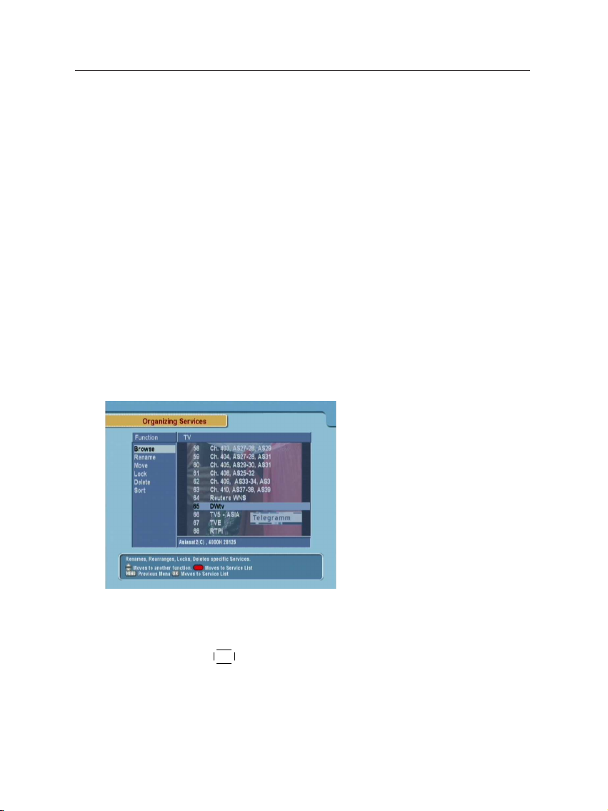
4.1 Editing The Services List
To edit the service list, select the
Organizing Services menu.
Browse
¤£¡
Press
OK button. Now, browsing through the Organizing Ser-
vices is possible. Press assigned buttons on the help message.
¢
Page 33

4.1 Editing The Services List 29
Rename
¤£¡
OK button
¢
¤£¡
OK button to
¢
Move
Usea,cbuttons to select Rename item and press
to move the cursor to the Service List. Press
display keyboard, and rename the service. After renaming it,
be sure to save it by pressing
¤£¡
OK button at Save item.
¢
Lock
Delete
Sort
You can reorder and move the service to the preferred position. Mark the desired service to move and press
Usea,cbuttons to choose the Move mode.
You can restrain and lock the services. From here, locking (and
later unlocking) services in any of the lists is possible e.g. in
order to prevent children from watching it. If a locked service
is selected, you should enter the PIN code in order to enjoy it.
¤£¡
Press
OK button to delete services. The delete function dif-
fers from the skip function as it deletes the service completely.
Whereas, the skip function just makes the service invisible.
Note The Delete menu deletes the specified service perma-
You can sort and rearrange the service list.
¢
nently. The only way to undo it is to perform the service
search again.
¤£¡
OK button.
¢
Page 34
30 Listing Services
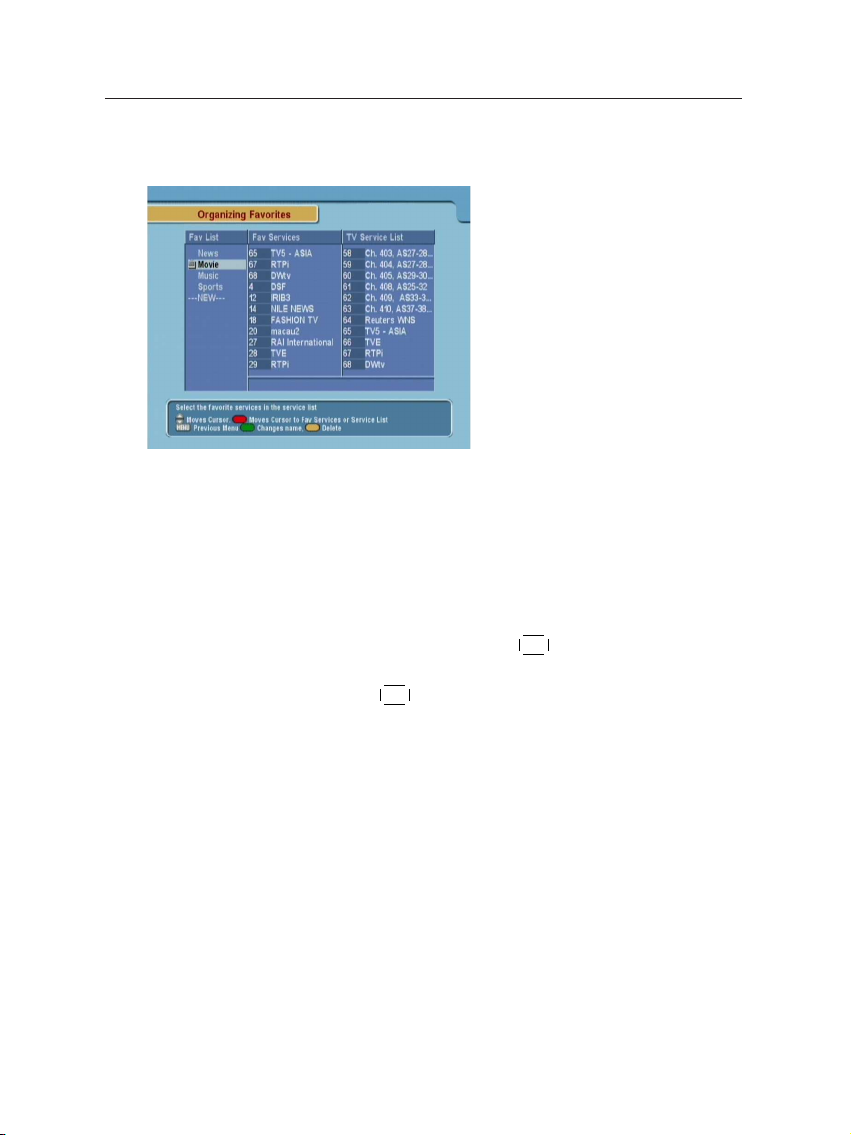
4.2 Editing The Favorites List
To edit the favorite services list,
select the Organizing Favorties
menu.
On the Fav List mode, four standard lists are selected as the
default menus: News, Movie Music and Sports. Up to 30 lists
including these lists can be added and renamed. When deleting a service, select a service in the Fav Services section and
press the assigned button on the help message.
To add services into Favorites, locate the cursor to the desired
service in Service List and press
vice from Favorites, locate the cursor to the service in Fav Ser-
vices and press
¤£¡
OK button.
¢
¤£¡
OK button. To delete a ser-
¢
Page 35

5.1 Browsing Services
31
Chapter 5
Daily Usage
¤£¡
Press
OK button to see the ser-
vice list then the service list with
the help window will be displayed. Select one of the services
you want to enjoy.
¢
By pressing the
lection window will appear. You can select a satellite there.
Sorting, alphabetic search and selecting a service by satellite is
possible.
¤£¡
0 button instead of
¢
¤£¡
OK button, satellite se-
¢
Page 36

32 Daily Usage
5.2 Information Box
Press the information button on the remote control to see
the program information. The Information box displays as follows:
Pressing
vice list pops up the multipicture selection window. Choose
any form you desire to view.
The multipicture function is also
available in the favorite list,
which appears on pressing the
¤£¡
FAV button.
¤£¡
M1 button in the ser-
¢
¢
• Service Number
• Service Name
• Detailed Program Informa-
tion
• Signal Level and Quality
• Satellite Information
• Information of subtitle and
teletext
• Parental Lock
You can hide the Information Box by pressing button.
Page 37

5.3 Electronic Program Guide 33
Service Name Frequency Signal Strength
Service Event Name Time CAS, Parental
Number Information Subtitle, Lock
Event Description Start Time – End Time / Dolby / Multifeed
Teletext Mark
You can see the Current/Next event by pressingb,dbutton
in the information box. To control the volume in the information box, you have to pressb/dbutton two times without
interval. If EPG is available on programs, by usingd,bbuttons, you can see the EPG. You can see extended information
of the event by pressing the information button once more.
5.3 Electronic Program Guide
To display the information about
currently being broadcasted as
well as those that will be broadcasted next, press
on the remote control unit. If
EPG is available on programs,
you will see the detailed description of the programs, start/end
time and programs schedules
etc.
¤
¡
GUIDE button
£
¢
buttons will be used to move program and to see next
a,c
program schedules.
buttons will be used to switch the service.
d,b
¤£¡
OK button makes the reservation for the next program. For
¢
a detailed description of the reservation method, refer to Section 3.2 on page 21.
button shows extended information of the event.
button will change the contents of EPG between TV and
Page 38

34 Daily Usage
Radio services.
¤£¡
F1 button switches the EPG from Single Service to Multi Ser-
¢
vice and in opposition.
5.4 Viweing Subtitle
You can choose a language of subtitle using the subtitle button
on the remote control. If the broadcaster provides subti-
tles, you can see the subtitle symbol in the Information Box.
5.5 Viewing Teletext
If the broadcaster supports teletext, you can see the teletext
symbol in the Information Box. There are VBI insertion
mode and software emulation mode in teletext. In the VBI insertion mode, which is always on, you can watch the teletext
with your TV using the remote control of your TV. To watch
teletext with VBI insertion, your TV must support teletext. In
the software emulation mode, you can watch the teletext even
though your TV does not support teletext. You can watch the
teletext using the remote control of digital receiver. Press the
teletext button to watch the teletext with software emulation mode. Press the teletext button once more or
button to escape from teletext.
¤£¡
EXIT
¢
Page 39

5.6 Selecting Sound Track 35
5.6 Selecting Sound Track
You can choose a language of
soundtrack by pressing the
sound button when a
broadcaster supports various
languages of soundtrack. Also,
it is possible to choose a mode
among Stereo, Mono, Left and
Right usingd,bbuttons. The
sound button is used for
multifeed function, too.
If the multifeed is available in current service, Multifeed Track
will be displayed first. You can change the display to Sound
Track selection menu by pressing the sound button once
more.
5.7 Selecting Multifeed
If multifeed is available in the service, the multifeed symbol
will appear at the right side of the Information box. If
available, the Multifeed Track and Sound Track are toggled
by the sound button . It is possible to choose one of the
multifeed services.
Page 40

36 Firmware Update and Data Transfer
Chapter 6
Firmware Update and Data
Transfer
The digital receiver has a stable and convenience firmware to
use. However, a new firmware may be released to improve the
digital receiver, The latest firmware and the update program
are available at Topfield website http://www.i-topfield.com.
To view the current information
of the digital receiver, select the
Information > IRD Status menu.
Page 41

6.1 Firmware Update 37
6.1 Firmware Update
6.1.1 From The Satellite
You can update the firmware using the method called OTA
(Over The Air). OTA is a standard for the transmission and
reception of application-related information in a wireless communications system.
To update the firmware by OTA,
press the Installation > Firmware
Upgrade menu.
The information of the satellite
available to update the digital receiver’s firmware by OTA is as
follows.
Satellite
Frequency 12603 MHz
Symbol Rate 22000 KS/s
Polarity Horizontal
PID 347
Astra
The satellite for OTA can be
changed. You can get the information at the Topfield website,
http://www.i-topfield.com.
6.1.2 From a Personal Computer via RS232 Port
It is possible to transfer a new firmware to the digital receiver
from a personal computer connecting them by a RS232 cable
to update the firmware. The firmware transfer program,
Down
is needed to use this method of update, which is avail-
able at the Topfield website,
How to update the firmware with this method is as follows.
http://www.i-topfield.com.
TFD-
Page 42

38 Firmware Update and Data Transfer
1. Download a new firmware applicable to the digital re-
ceiver from the Topfield website.
2. Download
3. Plug a RS232 cable into the RS232 port on the digital
receiver and the corresponding port on your computer.
4. Turn on the digital receiver.
5. Run
TFD-Down
TFD-Down
from the Topfield website.
.
How to use
TFD-Down
1. Press
firmware file.
2. Press
transfer.
3. Press
fer.
is as follows.
¤£¡
Find button to select the new
¢
¤
Download button to start the file
£
¤£¡
Stop button to cancel the file trans-
¡
¢
¢
6.1.3 From another Digital Receiver via RS232 Port
It is possible to transfer a new firmware to the digital receiver
from another digital receiver connecting them by a RS232 cable to update the firmware only if they are the same model.
How to update the firmware with this method is as follows.
1. Plug a RS232 cable into the RS232 port on the digital
receiver and the other’s.
2. Turn on them.
3. Select the Installation > Transfer Firmware to Other IRD
menu .
Page 43

6.2 Data Transfer 39
6.2 Data Transfer
From another Digital Receiver via RS232 Port
It is possible to transfer service information to the digital receiver from another digital receiver connecting them by a RS232
cable only if they are the same model.
The method is as follows.
1. Plug a RS232 cable into the RS232 port on the digital
receiver and the other’s.
2. Turn on them.
3. Select the Installation > Transfer Data to Other IRD menu.
Page 44

40 Information
Appendix A
Information
A.1 Operational Functions and Features
• Fully compliant with MPEG-2 digital and DVB
• DiSEqC 1.0, 1.1, 1.2 and USALS(DiSEqC 1.3) supported
• 5000 services programmable including radio service
• Multilingual audio supported
• Multilingual menu provided
• Service switching time less than 1 second
• Service list editable
• Favorite service list editable
• Favorite service groups available up to 30
• Automatic selection of color model
• 256 color on-screen display
• GMT and time offset supported
• Full picture in graphic function
• Electronic program guide supported
• Subtitle supported
• Teletext supported
• Access restriction function provided
• Firmware update and data transfer available between
the same receivers
Page 45

A.2 Technical Specification 41
• Exciting games embedded
• RCA AV output supported
• RF-modulator output supported
• Timer function provided
• Multipicture function provided
• User image display fuction provided in the radio mode
A.2 Technical Specification
Table A.1: Specifications of Tuner & Channel Decoder
Input/Loop through Connector F-type, IEC 169-24, Female
Frequency Range 950 to 2150 MHz
Signal Level Input −65 to −25 dBm
LNB Power & Polarization Vertical : +13.5 VDC
22 kHz Tone Frequency : 22 ± 1 kHz
Demodulation QPSK
Input Symbol Rate 1 to 45 MS/s
Code Rate 1/2, 2/3, 3/4, 5/6 and 7/8
Horizontal : +18.5 VDC
Current : Max. 500 mA with overload protection
Amplitude : 0.65 ± 0.2 V
Table A.2: Specifications of MPEG Transport Stream AV Decoding
Transport Stream ISO/IEC 13818-1 MPEG-2 Transport Stream
Profile Level MPEG-2 MP@ML
Aspect Ratio 4:3, 16:9
Video Resolution 720 × 576
Audio Decoding MPEG-1 Layer 1 and 2
Table A.3: Specifications of Connection Sockets
RCA A/V Video CVBS output
RS-232 9 pin D-sub type
Audio L/R output
Transfer rate : Max. 115.2 kbps
Page 46

42 Information
Table A.4: Specifications of RF-Modulator
Connector 75 Ω, IEC 169-2, Female/Male
Output Service CH21 – 69 (PAL) / CH14 – 83 (NTSC)
TV standard PAL G/I/K, NTSC-M
Table A.5: Specifications of Power Supply
Input Voltage 90 to 250 VAC, 50/60 Hz
Type SMPS
Power Consumption Running: Max. 24 W, Standby: 9 W
Protection Separate internal fuse.
Table A.6: Physical Specifications
Size (W × H × D) 260 × 46 × 190 mm
Weight 1.2 Kg
The input shall have lightning protection.
Page 47

Goto the position 43
Index
Symbol
16:9, 25
4 –18 (age), 23
4:3, 25
A
A/V Output Setting, 25
Access Control, 24
Advanced, 12
Auto, 12, 20
Auto/Manual, 20
B
Button, 3
Download, 38
Find, 38
Stop, 38
C
CAS, 13
Censorship, 23
Center extract, 25
Change PIN Code, 23
Conditional Access System, 13
D
Date, 22
Disable, 11
DiSEqC 1.0, 11
DiSEqC 1.1, 11
Download, 38
Duration, 22
E
East, 16
Every Weekday, 22
Every Weekend, 22
Everyday, 22
F
Factory Setting, 19
Fav List, 30
Fav Services, 30
favorite list, 32
Favorites, 30
Find, 38
Firmware Upgrade, 37
Free To Air, 13
FTA, 13
G
Goto, 15
Goto Ref, 15
Goto the position, 16
Page 48

44 Horizontal RF OUT
H
Horizontal, 17
I
Info Box Display Time, 26
Info Box Position, 27
Information, 36
Installation, 10, 12, 14, 15, 17,
19, 37–39
Installer, 14
IRD Status, 36
L
Language Setting, 24
Latitude, 16
Left, 25
Letter Box, 25
Limit E, Limit W, 15
Limit Off, 15
LNB, 10
LNB Frequency, 10
LNB IN, 7
LNB OUT, 7
LNB Setting, 10
Local Time, 20
Local Time Setting, 20
Locked, 24
Longitude, 16
Low Noise Block, 10
multipicture selection, 32
Music, 30
N
Network Information Table, 13
News, 30
NIT, 13
No Block, 23
North, 16
NTSC M, 26
O
OK, 18, 22
One Time, 22
Organizing Favorties, 30
Organizing Services, 28
OSD Transparency, 26
OTA, 37
Other, 18
Over The Air, 37
P
Packet Identifier, 13
PAL G, 26
PAL I, 26
PAL K, 26
PAL/NTSC, 25
Parental Control, 23
PID, 13
M
Manual, 12, 21
Mode, 20, 22
Mono, 25
Motorized DiSEqC 1.2, 14
Movie, 30
Multi, 25
multipicture, 32
R
R-AUDIO-L, 7
Recalculate, 15
Recover, 19
Rename, 29
Reset, 15
RF IN, 7
RF OUT, 7
Page 49

Right West 45
Right, 25
RS232, 7, 38, 39
S
SAT/TP Edit, 17
Satellite, 21
satellite list, 10, 12
Save, 18, 29
Service, 22
Service List, 30
service list, 31
Service Search, 12
SMATV, 12
South, 16
Space, 18
Sports, 30
Stereo, 25
Stop, 38
Store, 15, 19
System Setting, 20, 21, 23–27
T
TFD-Down, 37
Time Offset, 20
Total Block, 23
Transfer Data to Other IRD, 39
Transfer Firmware to Other IRD,
38
Type, 21
VIDEO, 7
W
Wakeup Time, 22
Weekly, 22
West, 16
U
Universal LNB, 10
USALS Setting, 15
User, 14
V
VCR Timer Setting, 21
Vertical, 17
Page 50

46
WEEE Information
Page 51

47484950515253
Page 52

Page 53

Page 54

Page 55

Page 56

Page 57

Page 58

Topfield continues to improve the digital receiver which this manual explains. So some explanations
and illustrations in this manual could be different from the real digital receiver.
Copyright © 2005, TOPFIELD Co., Ltd. English Version
http://www.i-topfield.com 110T-061B4-201-0 Rev. 1
 Loading...