

Page 1

TOPFIELD
TF 5000 PVRt
User Guide
Digital Terrestrial Receiver
Personal Video Recorder
Page 2

Page 3

Dear customer,
Topfield Australia congratulates you on your decision to purchase a digital set top box.
Are you aware that Topfield Australia have an Internet based
forum available to all our customers? We have over 10,000
users and over 50,000 articles posted so far, giving invaluable
hints and tips to enhance your Topfield digital experience.
If you require support on your Topfield product or have a
question which you don’t know the answer to, you can visit
our forum right now by going to http://www.topfield.com.
au, and clicking on the Forums icon at the top of the page,
it’s free to join and we even run occasional competition and
promotions for forum members only.
Thank you again for supporting Topfield.
Topfield Customer Service
iii
Page 4

iv Contents
Contents
1 Introduction 1
1.1 Features . . . . . . . . . . . . . . . . . . . . . . . . . . . . . . . 1
1.2 Controlling the digital receiver . . . . . . . . . . . . . . . . . . 2
1.2.1 The front panel . . . . . . . . . . . . . . . . . . . . . . . 3
1.2.2 The remote control . . . . . . . . . . . . . . . . . . . . . 4
2 Setup 8
2.1 Unpacking . . . . . . . . . . . . . . . . . . . . . . . . . . . . . . 8
2.2 Safety precautions . . . . . . . . . . . . . . . . . . . . . . . . . 9
2.3 Rear panel connections . . . . . . . . . . . . . . . . . . . . . . . 10
2.4 Connecting up your digital receiver . . . . . . . . . . . . . . . 12
2.4.1 Connecting the antenna . . . . . . . . . . . . . . . . . . 12
2.4.2 Connecting to your television . . . . . . . . . . . . . . 13
2.4.3 Connecting to your video cassette recorder . . . . . . . 15
2.4.4 Inserting batteries in the remote control . . . . . . . . . 15
3 Preference Settings 17
3.1 Language settings . . . . . . . . . . . . . . . . . . . . . . . . . . 17
3.2 Video and audio settings . . . . . . . . . . . . . . . . . . . . . . 19
3.2.1 Television standard . . . . . . . . . . . . . . . . . . . . 19
3.2.2 Colour model . . . . . . . . . . . . . . . . . . . . . . . . 20
Page 5

Contents v
3.2.3 Video cassette recorder . . . . . . . . . . . . . . . . . . 20
3.2.4 Television aspect ratio . . . . . . . . . . . . . . . . . . . 21
3.2.5 Sound mode . . . . . . . . . . . . . . . . . . . . . . . . 21
3.2.6 Radio frequency output . . . . . . . . . . . . . . . . . . 22
3.3 Local time setting . . . . . . . . . . . . . . . . . . . . . . . . . . 22
3.4 Parental control . . . . . . . . . . . . . . . . . . . . . . . . . . . 24
3.5 Adjusting the on-screen display . . . . . . . . . . . . . . . . . . 25
3.6 To turn on the time shift feature . . . . . . . . . . . . . . . . . . 26
4 Service Search 27
4.1 Searching broadcasting services . . . . . . . . . . . . . . . . . . 27
4.2 Resetting to factory settings . . . . . . . . . . . . . . . . . . . . 28
5 Daily Usage 29
5.1 Volume control . . . . . . . . . . . . . . . . . . . . . . . . . . . 29
5.2 Watching television . . . . . . . . . . . . . . . . . . . . . . . . . 29
5.2.1 The services list . . . . . . . . . . . . . . . . . . . . . . . 29
5.2.2 The favourite services list . . . . . . . . . . . . . . . . . 31
5.2.3 Viewing programme information . . . . . . . . . . . . 32
5.2.4 Selecting audio tracks . . . . . . . . . . . . . . . . . . . 33
5.2.5 Selecting subtitle tracks . . . . . . . . . . . . . . . . . . 33
5.2.6 Viewing teletext . . . . . . . . . . . . . . . . . . . . . . 33
5.3 Viewing electronic programme guide . . . . . . . . . . . . . . 33
5.4 Watching multifeed programme . . . . . . . . . . . . . . . . . 34
5.5 Using time shift . . . . . . . . . . . . . . . . . . . . . . . . . . . 35
5.6 Using picture in picture . . . . . . . . . . . . . . . . . . . . . . 36
6 Listing Services 38
6.1 Editing the favourite list . . . . . . . . . . . . . . . . . . . . . . 38
6.2 How to use on-screen keyboard . . . . . . . . . . . . . . . . . . 40
6.3 Transferring receiver data . . . . . . . . . . . . . . . . . . . . . 40
Page 6

vi Contents
7 Recording and Playing 42
7.1 Recording a programme . . . . . . . . . . . . . . . . . . . . . . 43
7.1.1 Instant recording . . . . . . . . . . . . . . . . . . . . . . 43
7.1.2 Current programme recording . . . . . . . . . . . . . . 45
7.1.3 Timer recording . . . . . . . . . . . . . . . . . . . . . . 46
7.1.4 Scheduling a recording using the programme guide . 48
7.1.5 Recording a time-shifted programme . . . . . . . . . . 49
7.2 File archive . . . . . . . . . . . . . . . . . . . . . . . . . . . . . 49
7.2.1 To delete a recording . . . . . . . . . . . . . . . . . . . . 50
7.2.2 To sort recordings . . . . . . . . . . . . . . . . . . . . . 50
7.2.3 To lock a recording file . . . . . . . . . . . . . . . . . . . 51
7.2.4 To rename a recording . . . . . . . . . . . . . . . . . . . 51
7.2.5 To make a new folder . . . . . . . . . . . . . . . . . . . 51
7.2.6 To move a recording to another folder . . . . . . . . . . 51
7.3 Playing back a recording . . . . . . . . . . . . . . . . . . . . . . 52
7.3.1 To navigate using the progress bar . . . . . . . . . . . . 52
7.3.2 To play in slow motion . . . . . . . . . . . . . . . . . . 53
7.3.3 To play in fast motion . . . . . . . . . . . . . . . . . . . 53
7.3.4 To make a bookmark . . . . . . . . . . . . . . . . . . . . 54
7.3.5 To play back a recording repeatedly . . . . . . . . . . . 54
7.3.6 To play back recordings in sequence . . . . . . . . . . . 55
7.4 Editing a recording . . . . . . . . . . . . . . . . . . . . . . . . . 55
7.5 Copying a recording . . . . . . . . . . . . . . . . . . . . . . . . 56
7.6 MP3 playback . . . . . . . . . . . . . . . . . . . . . . . . . . . . 57
7.7 Transferring recording files . . . . . . . . . . . . . . . . . . . . 57
7.8 Formatting the hard disk . . . . . . . . . . . . . . . . . . . . . . 59
8 Firmware Update 60
8.1 From your computer via USB port . . . . . . . . . . . . . . . . 61
8.2 From your computer via RS-232 port . . . . . . . . . . . . . . . 62
8.3 From another digital receiver via RS-232 port . . . . . . . . . . 63
Page 7

Contents vii
Index 64
Page 8

Page 9

Chapter 1
Introduction
The TF 5000PVRt digital receiver is fully compliant with the
international Digital Video Broadcasting (DVB) standard, and
can receive digital broadcasts. For its operation, you need an
antenna, which must be installed appropriately.
NOTE
In general we equate a channel with a frequency. However, unlike analogue broadcasts, digital broadcasts are not
all assigned to their own frequencies; instead, multiple television broadcasts are transmitted through a single frequency.
The frequency in digital broadcasting is usually called transponder. To reduce confusion in this manual, the word service
is preferably used than channel as a term to indicate one television or radio broadcast.
1
1.1 Features
The TF 5000 PVRt digital receiver has the following features:
• Can store up to 2000 television and radio services.
Page 10

2 Introduction
• You can make a favourite list with your favourite services.
• You can view information about the current television
or radio programme.
• Has an electronic programme guide that provides an
overview of programme schedules for next few hours.
• You can update the firmware of the digital receiver to
the latest version, which will be provided by the manufacturer.
• You can record one broadcasting service while you are
currently watching another.
• The large storage capacity of the built-in hard disk drive
allows you to record up to 80 hours of programme —in
case of 160 gigabytes— in excellent picture and sound
quality.
• Time shift is a special technical feature available on the
TF 5000 PVRt. You can pause the programme you are
watching and resume it again at a later time. Then
you can quickly go to whatever part of the current programme by fast foward and rewind search.
1.2 Controlling the digital receiver
The digital receiver can be operated with the remote control
and the buttons on the front panel.
NOTE
When the digital receiver is off but plugged into a wall outlet,
we say that it is in standby mode; on the other hand, when it is
on, it is in operation mode. Even when you are not using the
digital receiver, you should keep it plugged into a wall outlet
to be in standby mode so that it can run timer events at any
time.
Page 11

1.2.1 The front panel
TV/STB
OK
REMOTE
STANDBY
The front panel of the digital receiver has buttons to control
the digital receiver, and specific lamps and a display to indicate its status. The following indicates what they mean.
TV/STB lamp lights up while your video recorder operates
REMOTE lamp lights up whenever you press a button on
STANDBY lamp lights up while the digital receiver is in
Front display displays the current time in standby mode,
1.2 Controlling the digital receiver 3
instead of the digital receiver. See § 3.2.3 for more details.
the remote control.
standby mode.
and displays the current service in operation mode.
STANDBY button switches the digital receiver between
standby mode and operation mode.
MENU button displays the main menu. It is also used to
return to the previous menu from a submenu.
CHANNELa,cbuttons move to the next or previous ser-
vice. They are also used to navigate in the menus and
interactive screens.
VOLUMEb,dbuttons increase and decrease the volume.
They are also used to change options for a menu item.
OK button displays the services list. It is also used to select
menu items.
Page 12
4 Introduction
1
4
6
3
7
10
16
9
12
18
20
13
27
35
32
31
23
28
36
5
8
2
14
11
17
15
12
11
24
19
25
34
33
29
30
21
22
37
26
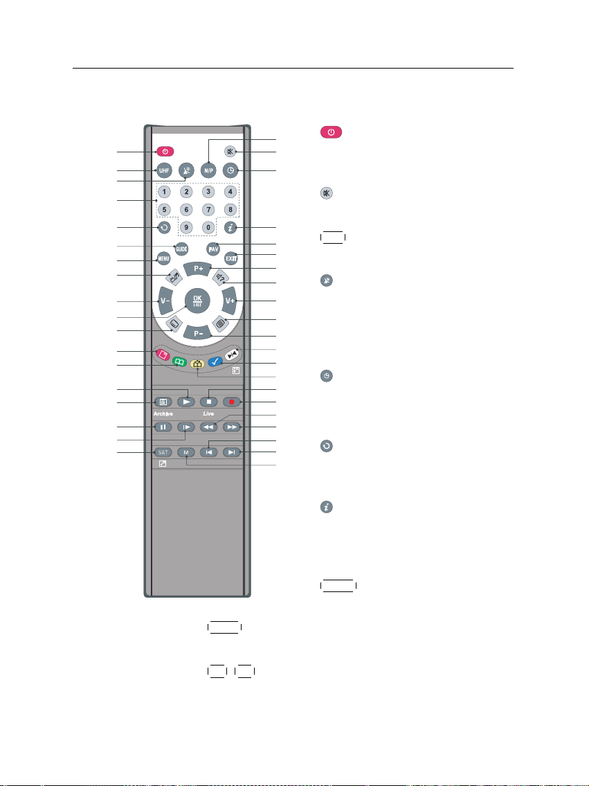
1.2.2 The remote control
1
2
3
4
5
6
10
MENU button displays the main menu. It is also used to
11
return to the previous menu from a submenu.
P+ ,
P− buttons move to the next or previous service.
7
8
9
They are also used to navigate in the menus and interactive screens.
button switches the digital receiver between standby mode and
operation mode.
button mutes the sound. Press
again to switch it back on.
UHF button displays the RF setting
menu. See § 3.2.6 for more details.
button switches the output of
the TV SCART socket between the
digital receiver and the device connected to the VCR SCART socket.
See § 3.2.3 for more details.
button sets a sleep timer.
Numeric buttons are used to enter
service numbers and menu options.
button switches between the
current service and the previously
viewed one.
button displays more information about the current programme
or a programme highlighted in the
electronic programme guide.
GUIDE button displays the elec-
tronic programme guide.
Page 13

1.2 Controlling the digital receiver 5
12
V+ ,
V− buttons increase and decrease the volume.
They are also used to change options for a menu item.
13
OK button displays the services list. It is also used to
select menu items. See § 5.2.1 for more details.
14
FAV button displays the favourite list.
15
EXIT button is used to leave the current screen.
16
button switches between television services and ra-
dio services.
17
button is used to select an audio track and sound
mode, or a video track of multifeed programme.
18
button is used to select a subtitle track.
19
button displays teletext.
20
button displays, minifies or hides the sub-screen. See
§ 5.6 for information about picture-in-picture.
21
button changes the position of sub-screen counter-
clockwise.
22
button changes the position of sub-screen clock-
wise.
23
SAT button swaps the sub-picture with the main picture.
24
button displays the services list for sub-screen. It is
also used to specify a block for editing or for repeated
playback.
25
button is used to edit a recording.
26
27
28
button plays from the next bookmark position.
button makes a bookmark on playback or time shift.
button resumes normal playback speed, or displayes the progress bar for navigation on playback or
time shift. To play a recorded programme, see button
35.
Page 14

6 Introduction
29
button rewinds. Subsequent presses change the
rewind speed.
30
button fast forwards. Subsequent presses change
the playback speed.
31
button starts slow motion playback. Subsequent
presses change the playback speed.
32
button pauses live television or playback of a
recorded programme.
33
34
button starts recording.
button is used to stop playback, to stop recording,
or to jump back to live television from time-shifted television.
35
button displays the list of recorded programmes
that are stored on the internal hard disk drive. See § 7.2
for detailed description.
36
N/P button is not used in this model.
37
M button is not used in this model.
If you do not have wide-screen television but normal screen
television, pressing the
0 button changes, depending on
broadcasting conditions, the display format as follows:
When you are viewing a wide-screen television, pressing the
0 button cycles through the display format options as follows:
4:3 Center Extract → 4:3 Letter Box → 16:9
The , , , and buttons have additional different
functions per menu besides their own function. They will be
guided by on-screen help.
If the remote control does not work, please check the remote
control mode. There are 4 modes with this remote control. You
can alter the mode by pressing two buttons simultaneously as
follows:
Page 15

1.2 Controlling the digital receiver 7
• Mode 1: +
• Mode 2:
• Mode 3: +
• Mode 4: +
1
+
2
3
4
The mode 1 will work at default.
Page 16

8 Setup
2.1 Unpacking
Chapter 2
Setup
Before going any further, check that you have received the following items with your digital receiver.
• Remote control unit
• Two batteries for the remote control (AAA 1.5 V)
• One loop cable, to connect the first tuner with the second
tuner
• One SCART-to-component cable, to link the digital receiver to your television set
• One S-Video cable, to link the digital receiver to your
television set
• One RCA AV cable, to link the digital receiver to your
television set
• A copy of this user guide
NOTE
Accessories may vary according to your local area.
Page 17

2.2 Safety precautions
Please read the following safety precautions carefully.
• The mains power must be 90 to 250 volt. Check it before
connecting the digital receiver to the wall outlet. For
the power consumption of the digital receiver, refer to
Table 2.1.
• The wall outlet should be near the equipment. Do not
run an extention lead to the unit.
• Do not expose the digital receiver to any moisture. The
digital receiver is designed for use indoors only. Use dry
cloth when cleaning the digital receiver.
• Place the digital receiver on a firm and level surface.
• Do not place the digital receiver close to heat emitting
units or in direct sunlight, as this will impair cooling.
Do not lay any objects such as magazines on the digital receiver. When placed in a cabinet, make sure there
is a minimum space of 10 centimetres around it. For
the physical specification of the digital receiver, refer to
Table 2.2.
2.2 Safety precautions 9
• Protect the power cord from being walked on or
pinched. If wires are exposed or cord is damaged, do
not use the digital receiver and get cord replaced.
• Never open the digital receiver casing under any circumstances. Warranty will be void.
• Refer all servicing to a qualified service technician.
Table 2.1: Power specification
Input voltage 90 to 250 V AC, 50/60 Hz
Power consumption 25 W at maximum in operation
8 W in standby
Page 18

10 Setup
ANT 1
RF LOOP 1 OUT RF LOOP 2 OUT AUDIO
L
R
S-VIDEO
VCR USB
RF IN
S/PDIF RS-232
VIDEO
TV
RF OUT
ANT 2
1
3 5 8 11
2 4 6 1210 13 149
7
Table 2.2: Physical specification
Size 340× 60× 265 mm
Weight 3.4 kg
Operating temperature 0 to 45 °C
Storage relative humidity 5 to 95 %
2.3 Rear panel connections
The TF 5000 PVRt has a wide range of connections on the back
panel.
Check what connections your television set has in comparison
with the digital receiver.
1
ANT 1 Terrestrial broadcasting signal input socket
for the first tuner.
2
RF LOOP 1 OUT Terrestrial broadcasting signal output
socket through the first tuner.
3
ANT 2 Terrestrial broadcasting signal input socket
for the second tuner.
4
RF LOOP 2 OUT Terrestrial broadcasting signal output
socket through the second tuner.
5
VIDEO Composite video output socket for the tele-
vision set. (yellow)
Page 19

2.3 Rear panel connections 11
6
AUDIO L/R Stereo audio output socket for the television
set or audio system. (white/red)
7
S-VIDEO Super video output socket for the television
set.
8
TV Audio and video output socket for the tele-
vision set.
9
VCR Audio and video input/output socket for
the video cassette recorder or suchlike.
10
USB USB port for firmware update and data
transfer.
11
RF OUT Analogue television output socket.
12
RF IN Analogue television input socket.
13
S/PDIF Dolby digital output socket for the audio
system.
14
RS-232 Serial port for firmware update and data
transfer.
Table 2.3: Connectors specification
VIDEO Composite video (CVBS) output
AUDIO Left & right audio output
S-VIDEO Super video (S-Video) output
TV CVBS/S-Video/RGB/YUV video output
Left & right audio output
VCR CVBS video output
Left & right audio output
CVBS/S-Video/RGB/YUV video input for bypass
Left & right audio input for bypass
S/PDIF Dolby digital audio output
RS-232 115.2 kbps at maximum
USB 2.0
Page 20

12 Setup
2.4 Connecting up your digital receiver
There are several ways to set up the digital receiver. Set up
the digital receiver suitably to your television and other appliances. If you have any problem with your setup or need help,
contact technical support on the back of this instuction book
under warranty information.
2.4.1 Connecting the antenna
Whatever sort of connection you have between the digital receiver and the television, you need to connect the digital receiver to your television antenna so that it can receive digital
television services.
Connect the antenna cable to the ANT 1
socket on the back panel of the digital receiver.
Also, you must ensure that there is a connection to both the ANT 1 and ANT 2 connectors
on your digital receiver, so that both tuners
work properly.
Normally you do that by using a loop cable to link from the
RF LOOP 1 OUT connector to the ANT 2 connector.
NOTE
However, if you are in a weak signal area, or are using a signal
amplifier with more than one output, you may achieve better
results by connecting a cable from the antenna or amplifier directly to the ANT 2 connector rather than using the loop cable.
If you have another digital receiver, or you want to still receive analogue channels on your television, link it from the
RF LOOP 2 OUT connector.
Page 21

2.4.2 Connecting to your television
Between all the following connectors of your digital receiver,
we recommend you use the first connector to get best picture
quality. If your television does not have the matching connector then use the next connector in the following order for best
picture quality.
1. SCART connector (TV)
2. S-Video connector (S-VIDEO)
3. Composite connector (VIDEO)
4. RF connector (RF OUT)
You should configure audio and video settings after connecting up the digital receiver. See § 3.2 for detailed description.
To use the SCART connector
For best results with a standard television
set, you should use a SCART cable, plugging
one end into the TV socket on the digital receiver and the other end into a free SCART
socket on your television.
Some televisions have inputs via Component or S-Video connectors rather than
SCART.
If you have such a television, use an appropriate conversion
cable to link the TV socket on the digital receiver to the matching socket on your television.
If you connect with a standard SCART cable, you do not have
to make audio connections because the SCART connector can
output stereo audio. But if you use a conversion cable, such as
SCART-to-Component, you have to make audio connections.
2.4 Connecting up your digital receiver 13
Page 22

14 Setup
To use the S-Video connector
To use the composite video connector
To connect the audio connectors
You will need to obtain a S-Video cable to
use the S-Video connector. Plug one end
of the cable into the S-VIDEO socket on the
digital receiver, and the other end into the
matching socket on your television.
You will need to obtain a composite video
cable (RCA cable) to use the composite video
connector. Plug one end of the cable into
the VIDEO (yellow) socket on the digital receiver, and the other end into the matching
socket on your television.
You will need to obtain an audio cable (RCA
cable) to connect the audio connectors. Plug
one end of the cable into the AUDIO L
(white) and AUDIO R (red) sockets on the
digital receiver, and the other end into the
matching sockets on your television or audio system.
To enjoy Dolby digital audio, your television or audio system must be able to decode
Dolby digital audio, and you will need toobtain a S/PDIF cable. Plug one end of the cable into the S/PIDF socket on the digital receiver, and the other end into the matching
socket on your audio system.
Page 23

2.4 Connecting up your digital receiver 15
To use the RF connector
If your television does not have any video and audio input,
you will need to use the radio frequency output from the digital receiver.
In this case, you will need to connect a cable from the RF OUT socket to the antenna
connector on your television. To ensure your
television can also pick up existing analogue
channels as well, you will need to connect
a cable from RF LOOP 2 OUT connector on
the back of the digital receiver to the RF IN
connector.
Tune your television to channel 36 so that you can see the output from the digital receiver.
2.4.3 Connecting to your video cassette recorder
The digital receiver can also output video to another appliance
such as a video cassette recorder or video receiver through an
auxiliary SCART connector.
You will need to obtain a SCART cable to
use the auxiliary SCART connector. Plug
one end of the cable into the VCR socket on
the digital receiver, and the other end into
the matching socket on your video cassette
recorder or suchlike.
2.4.4 Inserting batteries in the remote control
To insert the batteries, open the battery compartment by removing the lid, and then insert the batteries observing the polarity, which is marked on the base of the battery compartment.
If the digital receiver no longer reacts properly to remote control commands, the batteries may be flat. Be sure to remove
Page 24

16 Setup
used batteries. The manufacturer accepts no liability for damage resulting from leaking batteries.
NOTE
Batteries, including those which contain no heavy metals, may
not be disposed of with household waste. Please dispose of
used batteries in an environmentally sound manner. Find out
about the legal regulations which apply in your area.
Page 25

3.1 Language settings
17
Chapter 3
Preference Settings
You can select the language in
which the menu would be displayed. In addition to that, you
can select which language of audio track as well as of subtitle
track to be output.
Select the System Setting >
Language Setting menu. You
should see a screen like the left
figure.
Menu language
The digital receiver supports many menu languages: Dutch,
English, German, French, Italian, Russian, Turkish and so
forth. Set the Menu Language option to your desired language. Once you select a language, the menu will be immediately displayed in the selected language.
Page 26

18 Preference Settings
Subtitle language
Set the 1st Subtitle Language and the 2nd Subtitle Language
options to your desired languages. When you watch a programme, if the programme has a subtitle track of the language
that is designated for the 1st Subtitle Language, it will be displayed. If the first language is not available but the second
language is available, the subtitle track of the second language
will be displayed. If there is not any available language, no
subtitle will be displayed.
Apart from this setting, you can select a subtitle track with the
Audio language
Set the 1st Audio Language and the 2nd Audio Language options to your desired languages. When you watch a programme, if the programme has an audio track of the language
that is designated for the 1st Audio Language, it will be output. If the first language is not available but the second language is available, the audio of the second language will be
output.
Apart from this setting, you can select an audio track with the
button. See § 5.2.5 for further information.
button. See § 5.2.4 for further information.
Page 27

3.2 Video and audio settings
3.2.1 Television standard
The digital receiver supports two types of television standard.
One is the PAL standard, and the other is the NTSC standard. PAL was adopted in European countries while NTSC
is adopted in USA, Canada, Mexico and so forth. Refer to
Table 3.1 for television standard of your local area.
If you have a PAL television, you have to set the TV Type op-
tion to PAL. In this case, if a service is broadcasted in NTSC
standard, the digital receiver converts it into the PAL standard
for your PAL television. However, its quality would somewhat fall. The opposite case brings about the same result.
The best thing is to watch PAL services with a PAL television
and to watch NTSC services with a NTSC television. However, a multi television set is able to process both of them. So if
you have a multi television set, set the TV Type option to Multi.
With this option, the digital receiver will output them without
standard conversion. This setting is most recommended especially if you are not sure what standard type you have.
3.2 Video and audio settings 19
You have to configure the video
and audio settings appropriately to your television set and
appliances.
Select the System Setting >
A/V Output Setting menu. You
should see a screen like the left
figure.
Page 28

20 Preference Settings
3.2.2 Colour model
Through the TV SCART connector, the digital receiver is able
to output video in various colour models. If you have the
digital receiver linked to your television via this connector,
you should set the Video Output option to your desired colour
model. If you have connected via the RCA connector labeled
VIDEO on the back panel, you do not have to set this option
because the digital receiver outputs CVBS video through the
RCA connector independent of SCART connector.
However, if you have connected via the S-VIDEO connector,
you have to set this option to S-Video because the output
through S-Video connector comes from the SCART interface.
It is known in general that the RGB colour model provides the
best video quality with little difference from the YUV colour
model but the CVBS colour model does the least. So RGB
would be most desirable for this option.
3.2.3 Video cassette recorder
You can have the digital receiver linked to your video cassette
recorder or such an appliance via the VCR SCART connector. In that case, the digital receiver will operate differently
depending on the setting of the VCR Scart Type option. If
the option is set to Standard, the digital receiver will pass the
video from the video cassette recorder to your television when
it starts playback. But if the option is set to External A/V, the
digital receiver will not pass the video automatically. To pass
it, you have to press the
button.
NOTE
It is impossible for the digital receiver to record the video that
the video recorder plays back because the digital receiver is
just a bypass for the video recorder.
Page 29

3.2.4 Television aspect ratio
If you have a wide-screen television, set the TV Aspect Ratio
option to 16:9.
Otherwise, if you have a normal-screen television, set the TV
Aspect Ratio option to 4:3.
You cannot fully enjoy wide-screen programmes with your
normal-screen television as the above figures show. The left
figure shows a normal picture displayed in the normal screen.
To watch wide-screen programmes in the shape like the center
figure, set the 16:9 Display Format option to Letter Box. Wide-
screen pictures then will be reduced to fit to the width of the
normal screen. Otherwise, to watch them in the shape like the
right figure, set it to Center extract. Wide-screen pictures then
will be cut out on the left and right sides equally to fit to the
width of the normal screen.
3.2 Video and audio settings 21
NOTE
When watching television press the
tween normal and wide-screen formats.
3.2.5 Sound mode
Basically, there are two audio sources as you can find two audio sockets on the back panel of the digital receiver. You can
enjoy only one source or both of them in either stereo or mono.
Set the Sound Mode option as you desire.
Apart from this setting, you can change the sound mode with
the button. See § 5.2.4 for detailed description.
0 button to alternate be-
Page 30

22 Preference Settings
3.2.6 Radio frequency output
If you have connected your television to the RF OUT socket,
you should configure the radio frequency output. The digital
receiver can make analogue television from digital television
and output it through the RF OUT socket.
Set the RF Output option to the television standard that your
country supports referring to Table 3.1.
Table 3.1: Television standards by country
Signal type Country
PAL G Australia, Austria, Cyprus, Czech Republic, Egypt, Estonia, Finland, Ger-
PAL I Hong Kong, Macao, Republic of Ireland, South Africa, United Kingdom
PAL K Czech Republic, Hungary, Poland
NTSC M Bahamas, Belgium, Bolivia, Chile, Ecuador, Fiji, Guam, Jamaica, Mexico,
many, Greece, Iceland, Iran, Israel, Italy, Kuwait, Latvia, Libya, Lithuania,
Luxembourg, Netherlands, New Zealand, Norway, Portugal, Slovakia, Slovenia, Spain, Sweden, Switzerland, Syria, Yugoslavia
Panama, Peru, United States, Venezuela
Set the RF Channel option to a channel number as you desire.
You then have to retune your television set to the new channel
number.
3.3 Local time setting
You should set your local time for timer events.
Select the System Setting >
Time Setting menu. You should
see a screen like the left figure.
You can make the local time to
be automatically set by using
Greenwich Mean Time (GMT).
To use Greenwich mean time,
take the following steps:
Page 31

3.3 Local time setting 23
Table 3.2: Time offset table
Time offset City
GMT − 12:00 Eniwetok, Kwajalein
GMT − 11:00 Midway Island, Samoa
GMT − 10:00 Hawaii
GMT − 09:00 Alaska
GMT − 08:00 Pacific Time US, Canada
GMT − 07:00 Mountain Time US, Canada
GMT − 06:00 Central Time US, Canada, Mexico City
GMT − 05:00 Eastern Time US, Canada, Bogota, Lima
GMT − 04:00 Atlantic Time Canada, La Paz
GMT − 03:30 Newfoundland
GMT − 03:00 Brazil, Georgetown, Buenos Aries
GMT − 02:00 Mid-Atlantic
GMT − 01:00 Azores, Cape Verde Islands
GMT London, Lisbon, Casablanca
GMT + 1:00 Paris, Brussels, Copenhagen, Madrid
GMT + 2:00 South Africa, Kaliningrad
GMT + 3:00 Baghdad, Riyadh, Moscow, St. Petersburg
GMT + 3:30 Tehran
GMT + 4:00 Abu Dhabi, Muscat, Baku, Tbilisi
GMT + 4:30 Kabul
GMT + 5:00 Ekaterinburg, Islamabad, Karachi, Tashkent
GMT + 5:30 Bombay, Calcutta, Madras, New Delhi
GMT + 6:00 Almaty, Dhaka, Colombo
GMT + 7:00 Bangkok, Hanoi, Jakarta
GMT + 8:00 Beijing, Perth, Singapore, Hong Kong
GMT + 9:00 Tokyo, Seoul, Osaka, Sapporo, Yakutsk
GMT + 9:30 Adelaide, Darwin
GMT + 10:00 Eastern Australia, Guam, Vladivostok
GMT + 11:00 Magadan, Solomon Islands, New Caledonia
GMT + 12:00 Fiji, Auckland, Wellington, Kamchatka
1. Set the Mode option to Auto; then the Time Offset option
becomes enabled.
2. Set the Time Offset option to the time difference between
your time zone and GMT referring to Table 3.2.
3. Make sure that your local time is correctly displayed on
the Local Time option.
To set the local time yourself, set the Mode option to Man-
ual and enter your local time into the Local Time option with
Page 32

24 Preference Settings
the numeric buttons. The time format is day/month/year 24hour:minute.
3.4 Parental control
In general television programmes are classified according to
the level of violence, nudity and language of its content. When
you are watching a programme, you can check its programme
classification on the information box. For the information box,
see § 5.2.3.
You can prevent your children from watching specific programmes by specifying a programme classification.
Select the System Setting >
Parental Control menu. You
should see a screen like the
left figure, and you will be
asked your Personal Identification Number (PIN). The number
is initially set to 0000.
Set the Censorship option to your desired maximum programme classification for family viewing among the following:
No block restricts no prorgram.
Total block restricts every programme, even those with no
programme classification.
G restricts to G or above, which is all programmes with a
classification.
PG restricts to PG or above rated programmes. PG stands
for Parental Guidance, the content of which is mild.
Page 33

3.5 Adjusting the on-screen display 25
M restricts to M or above rated programmes. M stands for
Mature, the content of which is moderate in impact.
MA restricts to MA or above rated programmes. MA stands
for Mature Audiance, the content of which is strong.
R restricts to R rated programmes. R stands for Restricted
to adults aged 18 years or over, the content of which is
very strong.
AV restricts to AV rated programmes. AV stands for Adult
Viewing, the content of which is deep hardcore.
NOTE
If a programme does not have any programme classification
information, your censorship setting will not take effect.
If anyone is trying to watch a programme that is of or above
the censorship setting, the person has to enter the personal
identification number to override.
To change the number, select the Change PIN Code menu;
then an input box appears. You have to enter a desired number twice for confirmation.
You can also restrict uses of some menus. Selecting the Access
Control menu displays a list of menus that you can lock. If the
Time Setting item is set to Locked, you have to enter the per-
sonal identification number to access the Time Setting menu.
If you enter a wrong number, you cannot use the menu. To
release a shut item, set it to Unlocked.
3.5 Adjusting the on-screen display
You can adjust the transparency level of the on-screen display.
Select the System Setting menu and set the OSD Transparency
option as you desire. Its available range is from 0 to 50 percent.
You can adjust the display time of the information box. For
the information box, see § 5.2.3. To adjust its display time,
Page 34

26 Preference Settings
select the System Setting menu and set the Info Box Display
Time option as you desire. Its available range is from 1 to 30
seconds. If you set this option to No Info Box, the information
box will not be displayed when you switch services. However,
pressing the button will display the information box. If you
set this option to Never Hide, the information box will always
be displayed.
In addition, you can raise or lower the position of the information box. Select the System Setting menu and set the Info Box
Position option as you desire. Its available range is from −10
to +3 line. The more high the value is set, the more low the
information box will be positioned.
3.6 To turn on the time shift feature
Time shift means that the most recent hour of the television
service you are watching gets saved temporarily on the hard
disk of the digital receiver. When enabled, you can reverse
and pause live television as if playing back a recording. To
enable this feature, select the System Setting menu and set the
Time Shifting option to Enable. See § 5.5 for how to use this
feature.
Page 35

After connecting up the digital receiver, you will need to perform a service search.
4.1 Searching broadcasting services
27
Chapter 4
Service Search
To perform service search, select the Installation > Service
Search menu. You should see a
screen like the left figure.
If you have an antenna booster,
you should set the Antenna
Supply 5V option to On to supply power to it. (Not used in
Australia)
Auto search
You should set the Search Mode option to Auto for the first
time after connecting up the digital receiver; then the digital
receiver will search for all available services.
Page 36

28 Service Search
Manual search
Start search
You may choose to search only services of a specific transponder because more than one service are provided via each
transponder. To do that, set the Search Mode option to Man-
ual, and then at the Channel option select your desired transponder. The number ranges from 6 to 12 in VHF and 28 to 69
in UHF.
To search one service of a transponder, set the Search Mode
option to Advanced, and at the PID option specify the PIDs of
your desired service with the numeric buttons. PID (Packet
Identifier) is a set of numbers that identifies transport stream
packets.
To start service search, select the Start Search item; then a list
box appears, in which found services will be listed. When it
has completed, press the
To stop at any time, or to exit without saving, press the
button.
OK button to save found services.
EXIT
4.2 Resetting to factory settings
You can reset all data of the digital receiver. If you want to reset all the data, select the Installation > Factory Setting menu,
then you will be asked for confirmation. If you select Yes,
service entries, favourite entries and timer events will all be
deleted, and preference options will be reset to the manufacturer’s factory settings.
NOTE
Doing a factory reset will not delete any recorded items on the
hard disk drive.
Page 37

5.1 Volume control
Use the
able level. You may need to adjust the volume on your television set too. To temporarily switch off the sound, press the
button. Press it again to restore the sound to previous level.
V− and
Chapter 5
Daily Usage
V+ buttons to alter the volume to a comfort-
29
5.2 Watching television
To change services, press the
button switches to the previously viewed service. You can
switch to your desired service by entering its service number with the numeric buttons. You can also select a service
to watch in the services list.
5.2.1 The services list
To view the services list, press the
P+ or
P− button. Pressing the
OK button.
Page 38

30 Daily Usage
On the services list, you can see
the service information:
• Service number and name
• Transponder information
To select a desired service, put the highlight bar on its entry
with the
P+ or
P− button and press the
OK button; then it
will be presented.
Pressing the
V− or
V+ button skips over 10 entries up or
down. Entering a service number with the numeric buttons
puts the highlight bar on its entry.
Pressing the button displays the additional options, with
which you can do the following:
• By setting the Show Provider option to On, you can view
the provider of the services, which is usually the name
of the television company responsible for broadcasting
them.
• To change the name of the highlighted service, select the
Rename option; then the on-screen keyboard appears,
with which you can enter a new name. See § 6.2 for how
to use the on-screen keyboard.
• You can prevent other family members from watching
the highlighted service by setting the Lock option to
Locked. You have to enter your personal identification
number to watch or unlock it.
• To add the highlighted service into a favourite group, se-
lect the Add to Fav option; then the favourite groups will
Page 39

5.2 Watching television 31
be displayed. Put the highlight bar on a desired group
and press the
You can switch between the television services list and the radio services list by pressing the button.
5.2.2 The favourite services list
You can select a service to watch on a favourite list as well as
on the services list.
To select a favourite service, put the hightlight bar on a desired
group and press the
favourite services list. Once you select a desired service with
the
OK button, it will be presented. Otherwise, to select other
group, press the
After you have selected a favourite service, if you then switch
to another service using the
another favourite service of the selected group. The digital receiver will remind you what group you have selected by displaying its name at the top right of the screen whenever you
switch services. If you wish to get out of the current group,
select the All services group on the favourite list.
Besides that, you can add or delete a favourite group or service. To add the service you are currently watching into a
OK button.
To display the favourite lists,
press the
FAV button; it will be
displayed. As you move the
highlight bar up or down on the
favourite group list, favourite
services belonging to the highlighted group are listed.
For how to edit the favourite
lists, refer to § 6.1.
V+ button; a highlight bar appears on the
V− button.
P+ or
P− button, it will be also
Page 40

32 Daily Usage
favourite group, put the highlight bar of the group list on a desired group and press the
press the button. To delete a group or a service, press the
button.
5.2.3 Viewing programme information
Pressing button displays the information box, on which
you can see all of the following:
In addition, you might see the following symbols:
button. To create a new group,
• Service number and name
• Signal level and quality
• Programme name
• Programme classification symbol
• Programme summary
• Broadcasting time
• Current time
• Subtitle symbol ( ) if subtitle tracks are provided on the
current programme.
• Teletext symbol ( ) if teletext pages are provided on the
current service.
• Multifeed symbol ( ) if the current programme is provided in a multifeed service. To use this feature, refer to
§ 5.4.
Pressing the button once more displays detailed information about the current programme. To hide the information
box, press the
EXIT button.
Page 41

5.2.4 Selecting audio tracks
Some programmes are provided with audio tacks in one or
more languages. Pressing the button displays available audio tracks. Once you select an audio track, it will be sounded.
In addition, you can enjoy audio tracks in four sound modes:
Stereo, Mono, Left or Right. However, if a multifeed programme is provided at the moment, video tracks will be displayed. In this case, you have to press the button once
more to select an audio track.
5.2.5 Selecting subtitle tracks
Some programmes are provided with subtitle tracks in one or
more languages. If the current programme provides subtitle
tracks, the subtitle symbol ( ) will be marked on the information box. Pressing the button displays available subtitle
tracks. Once you select a subtitle track, it will be displayed.
5.2.6 Viewing teletext
On some services, such information as weather reports, news
or stock quotations is provided by means of teletext. If the
current service provides teletext, the teletext symbol ( ) will
be displayed on the information box. Press the button to
view teletext pages.
Select a desired page to view by entering the page number
with the numeric buttons. You can zoom into a teletext page
with the button, and adjust its transparency with the
button. To hide the teletext screen, press the
5.3 Viewing electronic programme guide 33
EXIT button.
5.3 Viewing electronic programme guide
The Electronic programme Guide shows the current and
scheduled programmes that are or will be available on each
service with a short summary for each programme.
Page 42

34 Daily Usage
Pressing the
plays the electronic programme
guide, on which you can see the
following:
• Scheduled programmes
• programme summary
• Broadcasting date
• Broadcasting time
GUIDE button dis-
To see detailed information of a desired programme, put the
highlight bar on your choice with the
press the button. To switch to another service, press the
or
V+ button. You can travel over previous days with the
button, and can travel over next days with the button.
To see the programme guide for radio broadcasts, press the
button. To switch it back, press the button again.
Pressing the button displays the programme guide in the
form of a spreadsheet. To switch it back, press the button
again.
You can make a timer recording on the electronic programme
guide. See § 7.1.4 for detailed description.
5.4 Watching multifeed programme
Some broadcasts such as sports channels can provide a variety
of perspectives on a programme at the same time. We call it a
multifeed programme. You can select and watch a perspective
you prefer.
If a multifeed programme is provided on the current service,
the multifeed symbol ( ) will be marked on the information
box. Press the button, then available video tracks will be
listed. Once you select one, it will be presented. At this time,
P+ or
P− button and
V−
Page 43

you have to press the button once more to select audio
tracks.
5.5 Using time shift
You can pause and resume a live TV programme, and even
rewind and replay it. When you are watching a programme
and you miss something you can rewind and replay it. Or
when your attention is needed elsewhere you can pause it and
resume it a short time later without losing any of it.
5.5 Using time shift 35
When you do this you are no
longer watching the live programme, instead you are watching a delayed presentation of it.
This is called time shifted television. Then, you can skip commercials until you catch up to
the live broadcast.
In order to use the time shift
feature, the Time Shifting option
must be set to Enable. See § 3.6.
When enabled, the digital receiver will keep as much as one
hour recording buffer of current service by utilizing the hard
disk drive storage. The buffer will reset each time you change
to another service.
With time shift enabled, the following operations are possible:
• To go back in time, hold down the button; to go
forward, hold down the button. The progress bar
is displayed momentarily with a preview window.
• You can navigate using the progress bar, refer to § 7.3.1.
• You can jump forward 30 seconds at a time by pressing
the button.
Page 44

36 Daily Usage
• You can jump backward 10 seconds at a time by pressing
the
• You can change playback speed. For slow motion see
§ 7.3.2. For fast motion see § 7.3.3.
• To check your current position in time shift, press the
gramme is displayed momentarily in top right corner of
screen. A value of −02:00 means two minutes behind
live programme.
• To make a recording of what is in time shift, see § 7.1.5.
• To end time shift, press the button. The live programme will be presented.
When time shift option is disabled and pause is kept for more
than 10 seconds, the time shift feature will be switched on to
stop you loosing part of the programme. In such case it will
remain enabled until you change services.
button.
button. The time difference compared to live pro-
5.6 Using picture in picture
You can watch two services
at the same time with one of
them presented in a sub-screen.
We call this feature picture-inpicture.
The instructions on how to
use the picture-in-picture feature are as follows:
1. Press the button to display a sub-screen, on which
another service will be presented.
Page 45

5.6 Using picture in picture 37
2. Pressing the button once more minifies the subscreen, and pressing it once again hides the sub-screen.
3. Pressing the
SAT button swaps the main picture with the
sub-picture. Even when you play back a recording, you
can watch a live programme in the sub-screen. However, you cannot swap the pictures in that case.
4. Pressing the button moves the sub-screen counterclockwise, and pressing the button moves it clockwise.
5. To display the services list for the sub-screen, press the
button.
NOTE
When a recording is in progress, the available services
in the services list may be limited.
Page 46

38 Listing Services
6.1 Editing the favourite list
You can make your own favourite services list. In fact, you can
define multiple favourite services lists, each being a ‘group’ of
chosen services.
Chapter 6
Listing Services
Select the Organizing Favorites
menu. You should see a screen
like the left figure.
There are 3 columns:
• Group list (left)
• Favourite list (centre)
• Services list (right)
The services list contains all available services, whereas the
favourite list contains only chosen services that have been
added to the highlighted group. As you move the highlight
bar up or down on the group list, favourite services belonging
to the highlighted group are shown in the favourite list.
Page 47

6.1 Editing the favourite list 39
You can add up to 30 groups. To add a group, select the NEW
option in the group list; then the on-screen keyboard appears.
See § 6.2 for how to use the on-screen keyboard.
To rename a group, put the highlight bar on a desired group
you wish to rename and press the button; then the onscreen keyboard appears. See § 6.2 for how to use the onscreen keyboard.
To delete a group, put the highlight baron a desired group you
wish to delete and press the button; then a confirmation
box appears. If you select Yes, it will be deleted.
You can add a favourite service to a group by performing the
following steps:
1. Put the highlight bar on a desired group entry in the
group list and press the
OK button to select it. The high-
light bar then moves to the services list.
2. To add a service to the selected group, put the highlight
bar on a desired service entry and press the
OK button.
The selected service entry is added to the favourite list.
Repeat this step to add more entries.
3. Press the button and the highlight bar is moved to
the favourite list. You can delete a favourite entry with
the
OK button.
4. To select another group, press the button again. By
pressing the button, the highlight bar is moved to
each column.
Besides, you can rearrange a group’s favourites by moving a
favourite entry. To move a favourite entry, put the highlight
bar on a desired entry to move and press the button; then
the selected entry becomes dark. Move it to a desired place
and press the
OK button.
To add radio services, press the button; then radio service
entries will be listed in the services list. To recall the television
Page 48

40 Listing Services
services list after adding radio services, press the button
again.
With your favourite services list, you can select your favourite
services more easily. Refer to § 5.2.2 for more information.
6.2 How to use on-screen keyboard
To delete a letter, put the cursor on a desired letter at the input
line and then select the Del key. You must select the Save key
to complete naming; otherwise, if you press the
it will not be named.
6.3 Transferring receiver data
The digital receiver retains such data as follows:
• Services list
• Favourite lists
• Preference settings
You can move the highlight key
horizontally with the
V+ buttons and vertically with
the
P+ and
ing the
ters its letter in the input line.
To type a space, select the Space
key. To type lower case letters or
numerals, select the Other key.
P− buttons. Press-
OK button on a key en-
EXIT button,
V− and
It is possible to transfer receiver data to your digital receiver
from another same digital by receiver connecting them with a
RS-232 cable.
To transfer receiver data, perform the following steps:
Page 49

6.3 Transferring receiver data 41
1. Plug one end of a RS-232 cable (9 pin D-
sub cable) into the RS-232 port on the
digital receiver, and the other end into
the matching port on the other digital receiver.
2. turn on the source digital receiver.
3. Select the Installation > Transfer Firmware
> Transfer Data to Other IRD menu.
4. To start the data transfer, turn on the target digital receiver.
NOTE
You had better memorize some important data such as video
settings before starting transfer to avoid loosing them.
Page 50

42 Recording and Playing
With one tuner of the digital receiver, you can record a service and at the same time watch another service—if the two
services are provided through the same transponder. The TF
5000 PVRt digital receiver has two tuners so that you can enjoy
the following:
• While playing a recording back, you can watch a service
Chapter 7
Recording and Playing
in the sub-screen using the picture-in-picture feature.
• You can record two different services while playing back
a previously recorded programme.
• You can record two different services while watching
one of them using the time shift feature. See § 5.5 for
the time shift feature.
• You can even record two different services while watching two other different services—only if two or more services are provided in a same transponder and the other
services are provided in another same transponder. In
this case you can watch two services at the same time
using the picture-in-picture feature. See § 5.6 for the
picture-in-picture feature.
Page 51

7.1 Recording a programme
Once recording has started, a symbol like the left figure will be displayed at the top right of the screen for
a few seconds. When you are watching a service different from the service being recorded, you can view a number
on the center of the symbol, which indicates the order that the
recording is started.
To record two programs simultaneously, two tuners are allocated for the recording. Therefore, you can only change to a
limited number of services while the two programs are being
recorded.
NOTE
Do not move the digital receiver nor pull off the plug while
it is running. It may damage recorded programmes. Note
that Topfield is not responsible for damages inflicted on files
that are stored on the hard disk drive.
When a recording is finished, it might not be saved if its
recording duration is less than one minute.
7.1 Recording a programme 43
7.1.1 Instant recording
To instantly record the programme you are watching at
present, press the button. Pressing the button will
not pause the current recording like it does with a video cassette recorder.
Page 52

44 Recording and Playing
Pressing the button will
pause the live show and begin
time shifting within the current
recording even with the Time
Shifting option disabled. However, it is still possible to pause
a recording. After a recording
is started, pressing the button displays a menu like the left
figure, in which you can set the
recording duration.
To specify an arbitrary recording duration, set the Duration option as you desire with the
OK button; the recording will end at the specified time.
V− and
V+ buttons and press the
If the information about the next programme is provided by
the electronic programme guide, the After this programme and
After next programme options will be available. Once the After this programme option is selected, the current recording
will stop when the current programme is scheduled to end.
Likewise, once the After next programme option is selected,
the current recording will stop when the next programme is
scheduled to end.
Selecting the Record pause option pauses recording. When
you press the button again, you will see this option is
changed to Record continue. To resume recording, select it.
Page 53

To additionally record another service, switch to the service
you want to record, and press the button.
Once a recording is started, it is put on the recorded programme list even though it is not finished yet. The recording
file is named after its service name with a suffix of a number. To view the recorded programme list, press the button. See § 7.2 for detailed description about the recorded programme list.
7.1.2 Current programme recording
7.1 Recording a programme 45
To stop recording, press the
button; then a box like
the left figure appears, which
shows programmes currently
being recorded. If you select
one, its recording will stop.
While a recording is going on,
you can watch or record another
service.
You can record the current programme including the bits that
you have already watched as
long as you have not changed
services at all. To do so, select
the Recording menu.
You can record two services at the same time. Set the Record
No option to distinguish two recordings.
Page 54

46 Recording and Playing
Set the Service option to the service which provides the programme you want. Pressing the
plays a services list, from which you can select your desired
service.
To start recording immediately from now on, set the Start
Time option to Quick. If you are watching a programme by
time shift and wish to record it from the beginning, set this
option to Current Event.
Set the Duration option to a desired time, in which the recording will be finished.
Pressing the
on-screen keyboard, with which you can specify a file name
for the timer recording. If you do not specify anything, it will
be named after the service name. See § 6.2 for how to use the
on-screen keyboard.
Once the Record Start option is selected, the recording is
started and the Stop option becomes enabled. To stop the
recording, select the Stop option.
7.1.3 Timer recording
You can input a programme to be recorded at a specific time.
Even if the digital receiver is off, it will turn on and start
recording at the specified time. The digital receiver will turn
off again when the recording is finished.
OK button on this option dis-
OK button on the File Name option displays the
To input a timer recording, select the System Setting > Timer
Setting menu; then the timer list
will be displayed.
To add a new timer event, press
the button, and a box like the
left figure appears. Take the following steps:
Page 55

7.1 Recording a programme 47
1. Set the Record option to On to make a recording. If
this option is set to Off, the digital receiver will turn on
at the specified time but not record; instead, you may
record with your video cassette recorder or suchlike in
this case.
2. If you want a radio programme, set the Type option to
Radio; otherwise, set it to TV.
3. Set the Service option to the service which provides the
programme you want. Pressing the
OK button on this
option displays a services list, from which you can select
your desired service.
4. There are five timer modes:
One Time means literally ‘one time.’
Every Day means literally ‘every day.’
Every Weekend means ‘Saturday and Sunday every
week.’
Weekly means ‘one day every week.’
Every Weekday means ‘from Monday to Friday ev-
ery week.’
If your favourite programme is broadcasted at weekends and you wish to record every episode of the programme, set the Mode option to Every Weekend.
5. Set the Date option to the desired date, on which
the digital receiver will turn on. The date format is
day/month/year-day of the week.
Set the Start Time option to a desired time, at which the
recording will be started. The time format is hour:minute.
6. Set the Duration option to a desired time, in which the
recording will be finished.
7. Pressing the
OK button on the File Name option dis-
plays the on-screen keyboard, with which you can specify a file name for the timer recording. If you do not
Page 56

48 Recording and Playing
specify anything, it will be named after the service
name. See § 6.2 for how to use the on-screen keyboard.
8. To set a timer recording with the above settings, select
the OK option; otherwise, it will not be saved and will
not occur.
You can also edit or delete timer events in the timer list.
To edit a timer entry, put the highlight bar on the entry you
want and press
can change its settings in the same manner as making a new
one.
To delete a timer event, put the highlight bar on the entry you
want to remove and press the button; then you are asked
for confirmation. If you select Yes, it will be deleted.
OK button; then appears a box in which you
7.1.4 Scheduling a recording using the programme guide
The provider of each service
probably only transmits information about the current and
next programmes. However, a
full week programme guide can
be obtained with a subscription
from a provider such as IceTV in
Australia http://www.icetve.
com.au. This lets you schedule
recordings by simply clicking
on the name of the programme.
For instructions on setting up IceTV, please visit http://www.
icetv.com.au/topfield. The instructions on how to make
timer recordings using the electronic programme guide are as
follows:
1. Press the
gramme guide.
GUIDE button to display the electronic pro-
Page 57

7.2 File archive 49
2. Select a service you want to record with the
buttons.
3. Select a programme you want to record with the
P− buttons.
4. To make a timer event without recording, press the
button; the letter P is displayed. To make a timer event
with recording, press it once more; then the letter R is
displayed.
5. This timer event is placed on the timer list. To change its
settings, press the button to show a box in which
you can edit. Refer to § 7.1.3 for detailed description.
6. To remove the marking, press the
7.1.5 Recording a time-shifted programme
See § 5.5 for detailed description about the time shift feature.
While watching a programme with time shift, you can record
it by performing the following steps:
1. Press the button to display the progress bar.
2. To move to the beginning of the desired scene, hold
down the or button until it is reached.
V− and
OK button once again.
P+ and
V+
OK
7.2 File archive
When a programme is recorded, it is stored as a file on the
built-in hard disk of the digital receiver. You can select a
recording to play back from the recorded programmes list.
3. Press the button to start recording. The time shift
buffer from that position onwards will now be recorded.
4. Press the button to stop time shift.
5. Press the button once more to stop recording.
Page 58

50 Recording and Playing
The file information is comprised of the following elements:
file number, file name, recording time, playing duration, file
size and so on.
You can play, move, delete, rename and lock a recording file.
You can also sort the recording files by file name, playing duration or file size. In addition, you can make a new folder.
7.2.1 To delete a recording
To delete a recording, put the highlight bar on it and press the
button; then you are asked for confirmation. If you select
Yes, it will be deleted.
Press the button to display
the recorded programmes list.
In addition to the recorded programmes list, there is the MP3
list. To view other lists, press
the or button. See § 7.6
for MP3 playback.
7.2.2 To sort recordings
To sort the recordings, perform the following steps:
1. Press the button to display the additional options.
2. Set the Sorting option to Alphabetic, Time or Size as you
want.
3. Press the
4. They are sorted by the specified option.
EXIT button.
Page 59

7.2.3 To lock a recording file
To lock a recording so that other people cannot play it, perform the following steps:
1. Put the highlight bar on a desired recording.
2. Press the button to display the additional options.
3. Set the Lock option to Locked.
4. Press the
5. The lock symbol ( ) is displayed on it.
If you select a locked recording to play it back, you will be
asked for your personal identification number.
7.2.4 To rename a recording
To change the name of a recording, perform the following
steps:
1. Put the highlight bar on a desired recording.
2. Press the button to display the additional options.
EXIT button.
7.2 File archive 51
3. Select the Rename option, and the on-screen keyboard
appears. Change the name and save it. See § 6.2 for how
to use the on-screen keyboard.
7.2.5 To make a new folder
To make a new folder, press the button; then a new folder
named GROUP # is created. You can change its name in the
same manner as renaming a recording. See above.
7.2.6 To move a recording to another folder
To move a recording to another folder, put the highlight bar on
a desired recording and press the button; then the folders
are listed. Once you choose a folder, the recording is moved
to it.
Page 60

52 Recording and Playing
7.3 Playing back a recording
When a programme is recorded, its additional contents such
as audio tracks or teletext are also recorded together. So you
can enjoy them while a recording is played.
The instructions on how to play a recording are as follows:
1. Press the button to display the list of recorded programmes.
2. Put the highlight bar on a desired recording.
3. Press the
4. To stop playback, press the button.
During a playback, you can enjoy the following tricks:
• To see the detailed information about the currently
played recording, press the button; then the information box appears and shows its file name, playing duration, programme information, and so on.
• To pause playback, press the button. To resume it,
press the button.
OK button to start playback.
• To go forward, hold down the button; to go backward, hold down the button.
• To display the progress bar, press the button; to
hide it, press the button again.
• when the progress bar is hidden, you can move to a desired scene by entering the percentage with the numeric
buttons
7.3.1 To navigate using the progress bar
First press the button to display the progress bar, then:
Page 61

• To go forward, hold down the button; to go backward, hold down the
• To bookmark a position refer to § 7.3.4.
• If there are no bookmarks, you can jump forward 30 seconds at a time by pressing the button.
• You can jump backward 10 seconds at a time by pressing
the button.
• To jump back to start of recording press the button.
• To jump to end of current recording press the button.
• To hide the progress bar, press the button again.
7.3.2 To play in slow motion
To watch in slow motion during a playback, press the
button. If you press it repeatedly, the playback speed changes
in 3 steps: 1/2, 1/4 and 1/8 times. To resume normal speed,
press the button.
7.3 Playing back a recording 53
button.
7.3.3 To play in fast motion
To watch in fast motion duration a playback, press the
button. If you press it repeatedly, the playback speed changes
in 3 steps: 2, 4 and 6 times. To resume normal speed, press the
button.
You can play not only forward but also backward in fast motion. To play backward, press the button. If you press it
repeatedly, the playback speed changes in 3 steps: 1, 2 and 3
times. To resume normal speed, press the button.
Page 62

54 Recording and Playing
7.3.4 To make a bookmark
1. Press the button to display the progress bar.
2. To add a bookmark, press the button at a desired
scene; then you will see a small dot appear above the
progress bar like in the picture above.
3. To jump forward to next bookmark, press the button.
You can mark favourite parts of
a recording by creating bookmarks, and jump to them. You
can have up to 64 bookmarks.
Bookmarks are stored with the
recording so that you can use
them again afterwards. To make
bookmarks, perform the following steps during playback:
4. To jump to first bookmark, press the button then
the button.
5. To delete a bookmark, jump to it and then press the
button.
7.3.5 To play back a recording repeatedly
You can play a recording repeatedly both in whole and in part.
To play a recording repeatedly in whole, press the button
when the progress bar is hidden; then the repetition symbol
( ) is displayed on the information box. To quit repeated
playback, press the button again.
To play a recording file repeatedly in part, perform the following steps:
Page 63

1. Press the button to display the progress bar.
2. Move to the beginning sceneof the part you want to play
repeatedly by holding down the or button.
3. Press the button, then the pointer starts to blink.
4. Move to the end scene; the part is marked in purple.
5. Press the button again, then the part turns green, and
repeated playback starts.
6. To cancel it, press the button when the progress bar
is displayed.
7.3.6 To play back recordings in sequence
You can play several recordings continuously in sequence by
performing the following steps:
1. Press the button to display the list of recorded programmes.
2. Select each desired recording with the button. When
a recording is selected, it is numbered.
3. Press the
4. The selected recordings are played in the sequence that
they are numbered.
OK button to start playback.
7.4 Editing a recording 55
5. To jump to start of next selected recording, press the
button to display the progress bar, then press the
button.
7.4 Editing a recording
You can cut out or save a part such as a commercial from a
recording by performing the following steps:
1. Press the button to display the progress bar during
a playback.
Page 64

56 Recording and Playing
2. Move to the beginning scene of the part you want to edit
by holding down the
3. Press the button, then the pointer starts to blink.
4. Move to the end scene; the part is marked in purple.
5. Press the button, then the edit options are displayed
6. If you choose the Cut option, it will be removed from the
original recording and discarded.
7. If you choose the Save option, the cut will be saved in
a new file which is named after the original recording
with a suffix of ‘CUT’ and a number.
7.5 Copying a recording
You can copy a recording file in whole or in part during a playback by performing the following steps:
1. Start playback of a recording you want.
2. Move to a scene from which you want to start copy by
holding down the or button.
or button.
3. Press the button, then it will be copied in a new file
which is named after the original recording with a suffix
of ‘COPY’ and a number.
4. To stop copy, press the button.
NOTE
You can make a copyof a long recording more quickly bystarting to play the original recording, then pressing button
until the speed has increased to six times, then pressing the
button. The copy will be done at six times normal speed.
Page 65

7.6 MP3 playback
You can enjoy music or audio books in MP3 format with the
digital receiver. For how to transfer MP3 files to the digital
receiver from your computer, refer to § 7.7.
To play a MP3 file, perform the following steps:
1. Press the button and then the or button
to display the MP3 list.
2. Put the highlight bar on a desired file; if you want to
play several files, select them with the button.
3. Press the
4. To stop playback, press the button.
To play all MP3 files in a subfolder, put the highlight bar on a
desired folder, and press the button.
OK button to start playback.
7.7 Transferring recording files
You can transfer files between the digital receiver and your
computer via USB connection with Altair, which is a program
used to transfer files. You can download it from the Topfield
web site, http://www.i-topfield.com.
To transfer files, take the following steps:
7.6 MP3 playback 57
Page 66

58 Recording and Playing
1. Download the Altair programme and the
USB driver from the Topfield web site.
2. Install them on your computer.
3. Plug one end of a USB cable into the USB
port on the digital receiver, and the other
end into the matching port on your computer.
4. Turn on the digital receiver.
5. Run Altair, then its screen will appear like
the figure below.
The instructions on how to use Altair are as follows:
1. Select files to transfer. The left panel shows files and
folders that are on the digital receiver, while the right
panel shows files and folders that are on your computer.
2. To transfer files from the digital receiver to your computer, press the right arrow button (→).
3. To transfer files from your computer to the digital receiver, press the left arrow button (←).
Page 67

At the top of the panel, you will see a message that says Turbo
Off. Turbo mode is a way of speeding up the transfer of files
to and from the digital receiver. You can click the circle to the
left of the message to turn turbo mode on or off.
Turbo mode makes transferring files faster, but the digital receiver stops responding to commands from the remote control. If you want to use the digital receiver while transferring,
or if any scheduled recordings are due to start, you should not
use turbo mode.
NOTE
You cannot play back the recordings with a regular MPEG
player on your computer because they are formatted differently from the standard MPEG format.
Visit http://www.videolan.org or http://www.elecard.com
where you can find a MPEG player able to play them back.
If you wish to author DVDs with them, visit http://www.
haenlein-software.com where you can find a DVD author-
ing program being able to process them.
7.8 Formatting the hard disk
7.8 Formatting the hard disk 59
To format the hard disk of the digital receiver, select the Installation > Format Hard Disk menu.
CAUTION
Formatting the hard disk will delete all files permanently.
NOTE
If a new hard disk drive is installed, it must be formatted because the file system of the digital receiver is different from
any of the personal computer. You can neither record nor use
time shift with an unformatted hard disk.
Page 68

60 Firmware Update
Chapter 8
Firmware Update
The digital receiver has a stable and convenient firmware to
use. However, anew firmware may be released to improve the
digital receiver. You can get the latest firmware and an update
utility from the web site, http://www.i-topfield.com.
You have to check the firmware
information of your digital receiver before downloading a
new firmware. Select the Infor-
mation > IRD Status menu. You
should see a screen like the left
figure.
NOTE
You can only update with new firmware of which System ID
is identical to yours. Otherwise you will fail in firmware update.
Page 69

8.1 From your computer via USB port 61
8.1 From your computer via USB port
You can transfer a new firmware to the digital receiver from
your computer by connecting them with a USB cable. You
need TFDN USB, a firmware transfer utility for this, which is
available from the web site, http://www.i-topfield.com.
To update the firmware with this method, perform the following steps:
1. Download a new firmware applicable to
the digital receiver from the Topfield web
site.
2. Plug one end of a USB cable into the USB
port on the digital receiver, and the other
end into the matching port on your computer.
3. Turn on the digital receiver.
4. Run TFDN USB.
The instructions on how to use TFDN USB are as follows:
1. Press the Find button to select the
new firmware file.
2. Press the Download button. To start
the file transfer, restart the digital
receiver.
3. When the file transfer is complete,
the display panel on the digital
receiver will count down to zero
while the new firmware is being applied.
4. Restart the digital receiver once
more.
Page 70

62 Firmware Update
8.2 From your computer via RS-232 port
It is possible to transfer a new firmware to the digital receiver
from your computer by connecting them with a RS-232 cable.
You need TFD-Down, a firmwaretransfer utility for this, which
is available from the web site, http://www.i-topfield.com.
To update the firmware with this method, perform the following steps:
1. Download a new firmware applicable to
the digital receiver from the Topfield web
site.
2. Turn off the digital receiver.
3. Plug one end of a RS-232 cable (9 pin Dsub cable) into the RS-232 port on the
digital receiver, and the other end into the
matching port on your computer.
4. Run TFD-Down.
The instructions on how to use TFD-Down are as follows:
1. Press the Find button to select the new
firmware file.
2. Press the Download button.
3. To start the file transfer, turn on the digital
receiver.
4. When the file transfer is complete, the
display panel on the digital receiver
will count down to zero while the new
firmware is being applied.
5. Restart the digital receiver.
Page 71

8.3 From another digital receiver via RS-232 port 63
8.3 From another digital receiver via RS-232 port
It is possible to transfer a new firmware to the digital receiver
from another same digital receiver by connecting them with a
RS-232 cable.
To update the firmware with this method, perform the following steps:
1. Turn off the target digital receiver.
2. Plug one end of a RS-232 cable (9 pin D-
sub cable) into the RS-232 port on the
digital receiver, and the other end into
the matching port on the other digital receiver.
3. If not already on, turn on the source digital receiver.
4. Select the Installation > Transfer Firmware
> Transfer Firmware to Other IRD menu.
5. To start the file transfer, turn on the target
digital receiver.
6. When the file transfer is complete, the
display panel on the digital receiver
will count down to zero while the new
firmware is begin applied.
Page 72

64 INDEX
Index
16:9, 21
16:9 Display Format, 21
1st Audio Language, 18
1st Subtitle Language, 18
2nd Audio Language, 18
2nd Subtitle Language, 18
4:3, 21
A/V Output Setting, 19
Access Control, 25
Add to Fav, 30
Advanced, 28
After next programme, 44
After this programme, 44
Alphabetic, 50
Altair, 57, 58
ANT 1, 12
ANT 1, 10
ANT 2, 12
ANT 2, 10
Antenna Supply 5V, 27
AUDIO L, 14
AUDIO L/R, 11
AUDIO R, 14
Auto, 27
AV, 25
Button, 4
Censorship, 24
Center extract, 21
Change PIN Code, 25
Channel, 28
Current Event, 46
Cut, 56
Date, 47
Download, 61, 62
Duration, 44, 47
DVB, 1
Electronic programme Guide, 33
Every Day, 47
Every Weekday, 47
Every Weekend, 47
Factory Setting, 28
File Name, 46, 47
Find, 61, 62
Format Hard Disk, 59
G, 24
GMT, 22
Info Box Display Time, 26
Info Box Position, 26
information box, 32
IRD Status, 60
keyboard, 40
Language Setting, 17
Letter Box, 21
Local Time, 23
Page 73

65
Lock, 30, 51
Locked, 51
M, 25
MA, 25
Manual, 28
Menu Language, 17
Mode, 23, 47
mono, 21
multifeed, 34
NEW, 39
No block, 24
normal-screen television, 21
NTSC, 19
on-screen keyboard, 39
One Time, 47
Organizing Favorites, 38
OSD Transparency, 25
PAL, 19
Parental Control, 24
PG, 24
picture-in-picture, 36
PID, 28
PIN, 24
progress bar, 49
Quick, 46
R, 25
Radio, 47
Record, 47
Record continue, 44
Record No, 45
Record pause, 44
Record Start, 46
recorded programmes list, 49
Recording, 45
Rename, 30, 51
RF Channel, 22
RF IN, 15
RF IN, 11
RF LOOP 1 OUT, 12
RF LOOP 1 OUT, 10
RF LOOP 2 OUT, 12
RF LOOP 2 OUT, 10
RF OUT, 15, 22
RF OUT, 11
RF Output, 22
RS-232, 41, 62, 63
RS-232, 11
S-VIDEO, 14
S-VIDEO, 11
S/PDIF, 11
S/PIDF, 14
Save, 56
Search Mode, 27, 28
Service, 46, 47
Service Search, 27
services list, 29
Show Provider, 30
Size, 50
Sorting, 50
Sound Mode, 21
Space, 40
specifications, 9–11
Start Search, 28
Start Time, 46, 47
stereo, 21
Stop, 46
subtitle, 33
System ID, 60
System Setting, 25, 26
teletext, 33
TFD-Down, 62
TFDN USB, 61
Time, 50
time format, 24
Time Offset, 23
Time Setting, 22, 25
Time Shifting, 26, 35, 44
timer list, 46
Timer Setting, 46
Total block, 24
Transfer Data to Other IRD, 41
Transfer Firmware to Other IRD, 63
Page 74

66 INDEX
transponder, 1
Turbo Off, 59
TV, 13, 47
TV, 11
TV Aspect Ratio, 21
TV Type, 19
Type, 47
USB, 58, 61
USB, 11
VCR, 15
VCR, 11
VCR Scart Type, 20
VIDEO, 13, 14
VIDEO, 10
Video Output, 20
Weekly, 47
wide-screen television, 21
Page 75

Warranty Information
Do not return this card to TOPFIELD AUSTRALIA
Equipment Details
Model Serial Number Date of Purchase
TF 5000 PVRt
Please keep warranty card, proof of purchase and all manuals in a safe place as you will require these when making
a warranty claim.
Ensure that the following conditions are followed when operating the equipment. Failure to do so may
result in warranty being void.
• Do Not place the unit in a confined cabinet or cupboard without proper ventilation.
• To prevent shock or hazard risk. Do Not place Liquid or Fluids near the appliance.
• Do Not place appliance in a dusty or wet location.
• Full warranty conditions are listed on the rear of this card.
For further Warranty information or to make a claim please contact Topfield Australia on 1300 889 803.
12 month warranty is offered by the Manufacturer Topfield Co.,Ltd.
Hanseo Bldg, 246-3, Seohyeon-dong, Bundang-gu,
Seongnam, 463-824, Korea.
Topfield Australia acts as the Service agent in Australia for the manufacturer’s warranty.
Topfield Australia
Unit 23, 62-66 Newton Road
Wetherill Park NSW 2164
Ph: 1300 889 803
Fax: 1300 789 803
Support email: support@topfield- australia.com.au
Web: http://www.topfield.com.au
Page 76

Warranty Conditions
1. Where required by Topfield Australia only the original invoice/receipt issued by the dealer will
be accepted as proof of purchase.
2. Topfield Australia may reject warranty claims on equipment which it believes to be illegally acquired or when the ‘owner ’ is unable to provide proof of purchase or where security labels or
serial numbers have been tampered with or removed.
3. The warranty covers only defects in the material and workmanship of the product for a period of
12 months from the date of original purchase.
4. This warranty is on ‘Return to Base’ basis. The owner is responsible for the delivery of the equipment to thepoint of purchase and for collecting the repaired or replaced equipmentfrom the same
location.
5. The warranty is void if failures arise as a result of any of the following.
a) Abuse, misuse, physical impact, normal wear and tear.
b) Alteration or repairs carried out without written authorization from Topfield Australia.
c) Upgrade that are not registered by Topfield Australia.
d) Operating or maintained other than in accordance with the manual supplied.
6. This equipment will not be considered defective as a result to incompatibility with other equipment or accessories other than the ones supplied with the unit at the time of purchase.
7. This unit should be returned in its original carton and protective packaging or alternatively in
a packing suitable to prevent damage. Topfield Australia will not accept any responsibility for
goods damaged whilst the goods are in transit.
8. Repair or replacement under the terms of this warranty does not give the right to extension or a
beginning of a new warranty period. Repairs or replacements may be carried out with functionally equivalent reconditioned parts or equivalent part. Parts that have been replaced become the
property of Topfield Australia.
9. The customer acknowledges that no promise representation or undertaking has been given by
Topfield Australia or its dealer in relation to equipment other than as contained in this warranty.
10. A service charge will apply if the fault is not covered within the conditions of this warranty or if
there is no fault found. The charge will be based on the current market rate.
11. Topfield Australia is not liable for any other loss other than the unit itself.
12. Nothing contained in this warranty shall be read or applied so as to affect the right of the consumer in relation to the provisions of the trade practices act or other statutory rights provided by
legislation of the state or territory. In the absence of applicable legislation this warranty will be
purchases sole and exclusive remedy and neither Topfield Australia nor its distributors or agents
shall be liable for any incidental or consequential damages for breach of any express or implied
warranty of this equipment.
Page 77

Page 78

Correct disposal of this product
This marking shown on the product or its literature indicates that it should
not be disposed with other household wastes at the end of its working life.
To prevent possible harm to the environment or human health from uncon-
trolled waste disposal, please separate this from other types of wastes and
recycle it responsibly to promote the sustainable reuse of material resources.
Household users should contact either the retailer where they purchased
this product or their local government office for details of where and how
they can dispose this product for environmentally safe recycling.
Business users should contact their supplier and check the terms and condi-
tions of the purchase contract. This product should not be mixed with other
commercial wastes for disposal.
Topfield continues to improve the digital receiver which this guide explains. So some ex-
planations and illustrations in this guide could be different from the actual digital receiver.
Copyright © 2007, Topfield Co., Ltd. Australian version
http://www.i-topfield.com 110T-F6227-20A-0 Rev. 1
 Loading...