

Page 1

INSTRUCTION MANUAL
ROTATING LASER
RL-SV2S
31366 90032
Page 2

Page 3

i
FOREWORD
Thank you for selecting the TOPCON instrument.
Please read this instruction manual carefully before using this instrument.
Verify that all equipment is included.
STANDARD SYSTEM COMPONENTS (p. iii)
The specifications and general appearance of the instrument are subject to change without
prior notice and without obligation by Topcon Corporation and may differ from those appearing
in this manual.
Some of the diagrams shown in this manual may be simplified for easier understanding.
Page 4

ii
HOW TO READ THIS MANUAL
Symbols
The following conventions are used in this manual.
:
Indicates precautions and important items which should be read before
operations.
:
Indicates the chapter title to refer to for additional information.
:
Indicates supplementary explanation.
Page 5

iii
STANDARD SYSTEM COMPONENTS
Please make sure that all of above items are in the box when you unpack.
*1), *2), *3)Batteries included in the package are to confirm the initial operation. Please replace
the batteries provided with new batteries (alkaline) as soon as possible.
Rechargeable battery type Dry battery type
1) RL-SV2S Instrument .......................................1pc.
2) Remote controller RC-60
(with AA Manganese battery x 2pcs.) .............1pc.
3) Level Sensor LS-80L.......................................1pc.
4) Model-6 Level Sensor Holder .........................1pc.
5) Battery holder DB-74C ....................................1pc.
6) Ni-MH battery pack BT-74Q............................1set
7) AC/DC converter AD-15..................................1pc.
8) AA-size dry cell batteries*1) ............................4pcs.
9) Carrying case ..................................................1pc.
10) Instruction manual ...........................................1vol.
1) RL-SV2S Instrument....................................... 1pc.
2) Remote controller RC-60
(with AA Manganese battery x 2pcs.) ............ 1pc.
3) Level Sensor LS-80L ...................................... 1pc.
4) Model-6 Level Sensor Holder ........................ 1pc.
5) Battery holder DB-74 ...................................... 1pc.
6) D-size dry cell batteries*2).............................. 4pcs.
7) AA-size dry cell batteries*3)............................ 4pcs.
8) Carrying case ................................................. 1pc.
9) Instruction manual .......................................... 1vol.
Page 6

iv
CONTENTS
FOREWORD ................................................................................................................................. I
HOW TO READ THIS MANUAL................................................................................................... II
STANDARD SYSTEM COMPONENTS ...................................................................................... III
CONTENTS.................................................................................................................................IV
1. PRECAUTIONS FOR SAFE OPERATION ............................................................................ 1
2. PRECAUTIONS ..................................................................................................................... 6
3. LASER SAFETY INFORMATION .......................................................................................... 8
Laser Safety................................................................................................................ 8
4. NOMENCLATURE ............................................................................................................... 11
4.1 RL-SV2S/RC-60 ........................................................................................................... 11
RL-SV2S Nomenclature............................................................................................ 11
RC-60 Nomenclature ................................................................................................ 12
RL-SV2S/RC-60 Key Operation................................................................................ 13
RL-SV2S/RC-60 Display........................................................................................... 14
4.2 Level Sensor LS-80L .................................................................................................... 15
LS-80L Nomenclature............................................................................................... 15
LS-80L Display.......................................................................................................... 16
LS-80L Detective Range........................................................................................... 17
5. PREPARATION AND FUNCTIONS..................................................................................... 18
5.1 Power Source ............................................................................................................... 18
RL-SV2S (Dry battery type) ...................................................................................... 18
RL-SV2S (Rechargeable battery type) ..................................................................... 20
Page 7

CONTENTS
v
RC-60........................................................................................................................23
LS-80L.......................................................................................................................23
5.2 How to set remote controller communication channel .................................................. 24
RL-SV2S ...................................................................................................................24
RC-60........................................................................................................................24
6. BASIC OPERATION.............................................................................................................25
6.1 Setting Up Instrument ...................................................................................................25
Horizontal Rotation....................................................................................................25
Example Operational.................................................................................................27
Vertical Rotation........................................................................................................ 27
6.2 Height Alert Function .................................................................................................... 28
How to reset.............................................................................................................. 28
7. APPLIED OPERATION AND SETTING OF VARIOUS FUNCTIONS.................................. 29
7.1 Setting Grades..............................................................................................................29
How to enter grade values ........................................................................................29
How to set grades .....................................................................................................31
Example of how to set up.......................................................................................... 33
Matching Mode (Manual Slope) ................................................................................ 35
7.2 Line Control (manual vertical beam alignment) ............................................................ 39
7.3 Setting of Various Functions......................................................................................... 43
Selecting MENU........................................................................................................ 43
Masking (Laser beam shutter) setting....................................................................... 44
How to change the rotary head speed ...................................................................... 45
Page 8

CONTENTS
vi
Switching Auto leveling / Manual Mode .................................................................... 46
Setting channel ......................................................................................................... 47
Sleep mode............................................................................................................... 48
Height Alert ON/OFF................................................................................................. 49
8. CHECK AND ADJUSTING................................................................................................... 50
8.1 Check and Adjust Horizontal Rotation.......................................................................... 50
Horizontal Rotation Grade Error ............................................................................... 50
Horizontal Rotation Cone Error................................................................................. 54
Grade Setting Error................................................................................................... 55
8.2 Vertical Calibration........................................................................................................ 57
Checking Calibration................................................................................................. 57
Vertical calibration and adjustment ........................................................................... 58
9. STORAGE PRECAUTIONS................................................................................................. 60
10. HOW TO STORE ................................................................................................................. 61
11. SPECIFICATIONS ............................................................................................................... 62
12. ERROR DISPLAY ................................................................................................................ 65
13. REGULATIONS.................................................................................................................... 68
Page 9
1
1. PRECAUTIONS FOR SAFE OPERATION
For the safe use of the product and prevention of injury to operators and other persons as well
as prevention of property damage, items which should be observed are indicated by an
exclamation point within a triangle used with WARNING and CAUTION statements in this
instruction manual.
The definitions of the indications are listed below. Be sure you understand them before reading
the manuals main text.
Definition of Indication
WARNING
Ignoring this indication and making an operation error could possibly
result in death or serious injury to the operator.
CAUTION
Ignoring this indication and making an operation error could possibly
result in personal injury or property damage.
This symbol indicates items for which caution (hazard warnings inclusive) is urged.
Specific details are printed in or near the symbol.
This symbol indicates items which are prohibited. Specific details are printed in or
near the symbol.
This symbol indicates items which must always be performed. Specific details are
printed in or near the symbol.
Page 10

1. PRECAUTIONS FOR SAFE OPERATION
2
General
Warning
Do not perform disassembly or rebuilding. Fire, electric shock or burns could result.
Do not use the unit in areas exposed to high amounts of dust or ash, in areas where
there is inadequate ventilation, or near combustible materials. An explosion could
occur.
When securing the instrument in the carrying case make sure that all catches,
including the side catches, are closed. Failure to do so could result in the
instrument falling out while being carried, causing injury.
Caution
Do not use the carrying case as a footstool. The case is slippery and unstable so a
person could slip and fall off it.
Do not place the instrument in a case with a damaged case or belt. The case or
instrument could be dropped and cause injury.
Page 11
1. PRECAUTIONS FOR SAFE OPERATION
3
Power Supply
Warning
Do not short circuit. Heat or ignition could result.
Do not use voltage other than the specified power supply voltage. Fire or electrical
shock could result.
Do not use damaged power cords, plugs or loose outlets. Fire or electric shock
could result.
Do not use power cords other than those designated. Fire could result.
Do not use batteries other than those designated. An explosion could occur, or
abnormal heat generated, leading to fire.
Do not place articles such as clothing on the battery charger while charging
batteries. Sparks could be induced, leading to fire.
Use only the specified battery charger to recharge batteries. Other chargers may
be of different voltage rating or polarity, causing sparking which could lead to fire or
burns.
Page 12

1. PRECAUTIONS FOR SAFE OPERATION
4
Do not heat or throw batteries into fire. An explosion could occur, resulting in injury.
Do not use the battery or charger for any other equipment or purpose. Fire or burns
caused by ignition could result.
To prevent shorting of the battery in storage, apply insulating tape or equivalent to
the terminals. Otherwise shorting could occur, resulting in fire or burns.
Do not use batteries or the battery charger if wet. Resultant shorting could lead to
fire or burns.
Do not connect or disconnect power supply plugs with wet hands. Electric shock
could result.
Caution
Do not touch liquid leaking from batteries. Harmful chemicals could cause burns or
blisters.
Page 13
1. PRECAUTIONS FOR SAFE OPERATION
5
Tripod
Caution
When mounting the instrument to the tripod, tighten the centering screw securely.
Failure to tighten the screw properly could result in the instrument falling off the
tripod, causing injury.
Tighten securely the leg fixing screws of the tripod on which the instrument is
mounted. Failure to tighten the screws could result in the tripod collapsing, causing
injury.
Do not carry the tripod with the tripod shoes pointed at other persons. A person
could be injured if struck by the tripod shoes.
Keep hands and feet away from the tripod shoes when fixing the tripod in the
ground. A hand or foot stab wound could result.
Tighten the leg fixing screws securely before carrying the tripod. Failure to tighten
the screws could lead to the tripod legs extending, causing injury.
Page 14

6
2. PRECAUTIONS
Before starting work or operation, be sure to check that the instrument is functioning correctly
with normal performance.
Vibration and Impact Protection
When transporting the instrument, provide protection to minimize risk of severe vibration or
impact. Severe vibration or impacts may affect beam accuracy.
Sudden changes of temperature
A sudden change in temperature may cause water condensation on the glass used for the laser
emission part.
In such a case, let the instrument stand for a while to allow it to adjust to the temperature prior
to actual use.
Exceptions from Responsibility
The user of this product is expected to follow all operating instructions and make periodic
checks of the products performance.
Page 15

2. PRECAUTIONS
7
The manufacturer, or its representatives, assumes no responsibility for results of a faulty or
intentional usage or misuse including any direct, indirect, consequential damage, and loss of
profits.
The manufacturer, or its representatives, assumes no responsibility for consequential
damage, and loss of profits by any disaster, (an earthquake, storms, floods etc.). A fire,
accident, or an act of a third party and/or a usage any other usual conditions.
The manufacturer, or its representatives, assumes no responsibility for any damage, and loss
of profits due to a change of data, loss of data, an interruption of business etc., caused by
using the product or an unusable product.
The manufacturer, or its representatives, assumes no responsibility for any damage, and loss
of profits caused by usage except for explained in the user manual.
The manufacturer, or its representatives, assumes no responsibility for damage caused by
wrong movement, or action due to connecting with other products.
Page 16

8
3. LASER SAFETY INFORMATION
The RL-SV2S is classified as a class 3R Laser Product according to IEC Standard Publication
60825-1 Ed.2.0: 2007 and United States Government Code of Federal Regulation FDA CDRH
21CFR Part1040.10 and 1040.11 (Complies with FDA performance standards for laser products
except for deviations pursuant to Laser Notice No.50, dated June 24, 2007.)
Laser Safety
This product projects a visible laser beam during operation. This product is manufactured and
sold in accordance with Performance Standards for Light-Emitting Products (FDA/BRH 21
CFR 1040) or Radiation Safety of Laser Products, Equipment Classification, Requirements and
Users Guide (IEC Publication 60825-1) provided on the safety standards for laser beam.
As per the said standard, RL-SV2S standard model is classified as Class 3R (IIIa) Laser
Products. These are simple products to operate and do not require training from a laser safety
officer. In case of any failure, do not disassemble the instrument. Contact TOPCON or your
TOPCON dealer.
Page 17
3. LASER SAFETY INFORMATION
9
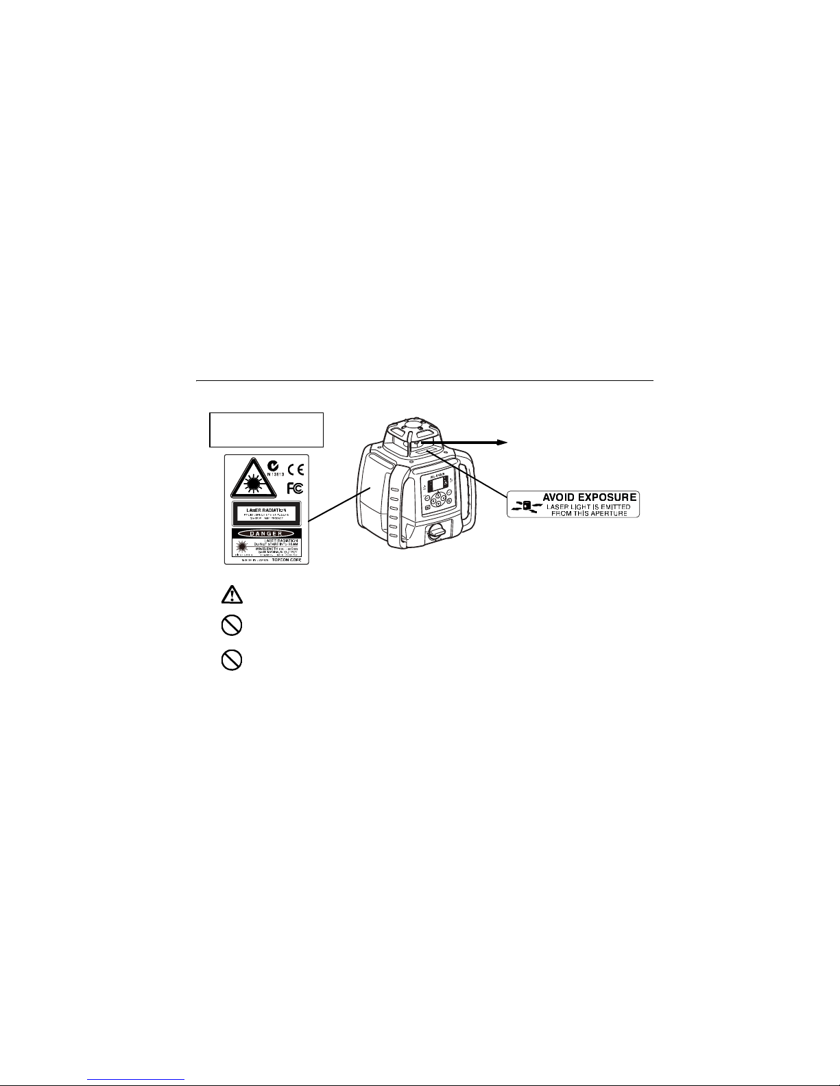
Warning
Use of controls or adjustments or performance of procedures other than those
specified herein may result in hazardous radiation exposure.
Do not look directly into the laser beam. Doing so could cause permanent eye
damage.
Visible laser
Laser output: 2.4mW
Beam aperture
Explanatory Label
Each label is differed by the market.
Page 18
3. LASER SAFETY INFORMATION
10
Do not stare at the laser beam. Doing so could cause permanent eye damage.
If an eye injury is caused by exposure to the laser beam, seek immediate medical
attention from a licensed ophthalmologist.
Caution
Perform checks at start of work and periodic checks and adjustments with the laser
beam emitted under normal conditions.
When the instrument is not being used, turn off the power.
When disposing of the instrument, destroy the battery connector so that the laser
beam cannot be emitted.
Operate the instrument with due caution to avoid injuries that may be caused by
the laser beam unintentionally striking a person in the eye. Avoid setting the
instrument at heights at which the path of the laser beam may strike pedestrians or
drivers at head height.
Page 19
11
4. NOMENCLATURE
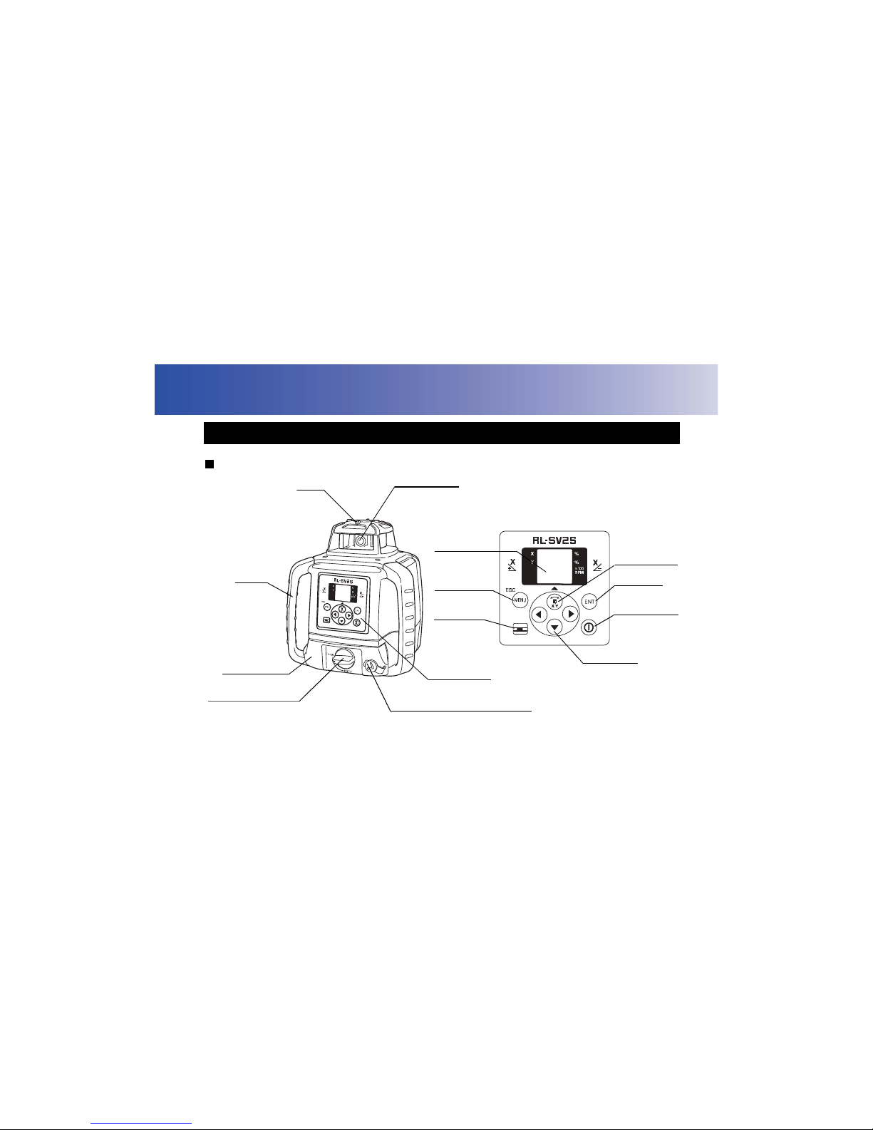
RL-SV2S Nomenclature
4.1 RL-SV2S/RC-60
Control panel
Handle
Battery holder
Control panel
Charging connector (only in
the rechargeable battery type)
Sight
Rotary head
Beam aperture
Battery holder knob
Enter key
Power switch
X/Y axis
selection key/
Alignmentkey/
Up key
Menu key/
Escape key
Level vial
For Vertical
Rotation
Arrow keys
Display
Page 20
4. NOMENCLATURE
12
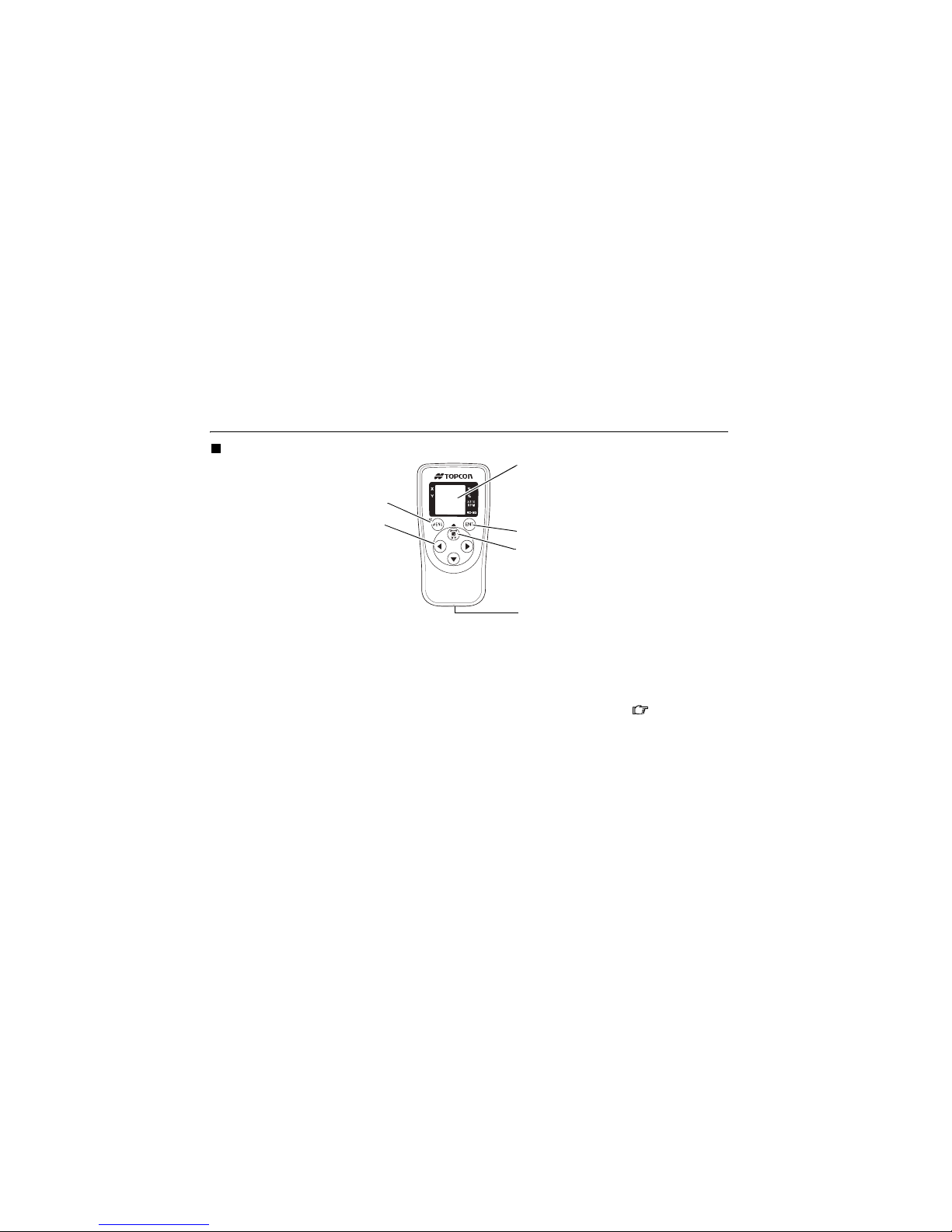
RC-60 Nomenclature
Turn ON the power of the RL-SV2S before using the RC-60.
Pressing one of the keys (or inserting the battery) will display the channel search (CH SErCH)
and begin transmission with the RL-SV2S.
When the channel is not aligned with the RL-SV2S or when the RL-SV2S power is not turned
ON, the display will show "Transmission error with remote control" (p. 66). 12. ERROR
DISPLAY(p. 65), Setting channel (p. 47)
Auto-cut off function: The power will turn OFF automatically if no key is pressed for
approximately 6 minutes. (To resume, press one of the keys to display the channel search [CH
SErCH] and transmission with the RL-SV2S will begin.)
Display
Enter key
X/Y axis selection key/Alignment key/
Up key
Strap hole
Menu key/Escape key
Arrow keys
Page 21

4. NOMENCLATURE
13
The RC-60 is a remote controller specifically designed for the RL-SV2S and cannot be used
with other models.
RL-SV2S/RC-60 Key Operation
Key Nomenclature Function
Enter key
End Operation of Data Input and Sends data to the
instrument.
Menu/Escape key
Selects a menu item.
Cancels input or escape to previous status.
X/Y axis selection key/
Alignment key
Horizontal rotation: changes to the grade setting screen for
each axis.
Vertical rotation: changes to the Alignment Mode.
Arrow keys
The arrows indicate code selection, digit shift, and number
input during grade setting, and designates direction during
masking setting.
Power switch
(For only the RL-SV2S)
On/Off of the RL-SV2S.
Page 22

4. NOMENCLATURE
14
RL-SV2S/RC-60 Display
Sample display
X axis grade
Transmission and reception display
Battery remaining
Y axis grade
Rotation speed
6:600 rpm
3:300 rpm
5:500 rpm
(Flashes when the battery is low)
Transmits to the receiving instrument (RC-60 or
RL-SV2S)
(Lights on until received by the receiving
instrument)
Receives from the transmitting instrument
(Lights on until the transmitting instrument
transmits next time)
When transmission from the other instrument
is not possible
(Both marks will flash slowly until the next
transmission)
Ample power for operation
Ample power for operation
Power remaining for operation
*1)
(Flashes one digit at a time
during auto leveling)
(Flashes one digit at a time
during auto leveling)
Manual Mode display
Mask Mode display
Power remaining for operation
Near power depletion
*2)
Power depletion
Laser will stop
Dry cell battery type: Replace with new batteries.
Rechargeable battery type:
When connecting to AD-15
during errordisplay, turn OFF the
power and then turn the power
back ON to restore operation.
*1), *2) The laser speed will be 500 rpm.
(Battery power display for the RC-60 shows the remaining
battery level on the RC-60 remote controller.)
Page 23

4. NOMENCLATURE
15
LS-80L Nomenclature
4.2 Level Sensor LS-80L
Beam receiving window
Turn the beam receiving window side
towards RL-SV2S to detect the laser
beam.
Buzzer sound switch
Volume of the sensor buzzer can be
alternately switched to
LOW/LOUD/OFF by pressing the switch.
Index
On-Grade precision switch
Two on-grade precision options are
available, normal precision (±2mm)
and high precision (±1mm). By
pressing this switch, the precision
options are switched alternately.
Confirm the precision choice by the
indicator. (Normal precision is the
default setting each time the sensor
is turned on.)
Power switch
The power switch turns ON or OFF
by pressing.
Buzzer speaker
Indicator LS-80L Display (p. 16)
Detect the on-grade position "---" by moving
the LS-80L up and down. Directional arrows
and audio signals assist in locating the on-
grade position as the laser strikes the beam
receiving window. (Top of LS-80L is 40mm
(1 9/16") from on-grade index for offset
marking.)
The indicators are located on front and back
sides of the instrument.
Auto-cut off function
The power will be turned off automatically if no laser beam is
detected for approximately 30 minutes. (To turn on the level sensor,
press the power switch again.)
Page 24

4. NOMENCLATURE
16
LS-80L Display
Normal precision mode
High precision mode
Higher than datum position
(Buzzer sound:High frequent beep sound)
Move the sensor downward.
Datum position
(Buzzer sound:Continuous beep sound)
Lower than datum position
(Buzzer sound:Low frequent beep sound)
Move the sensor upward.
Battery remaining display
Height alert warning ofrotating
laser
*1
Rotating laser battery
warning
*2
The warning displays *1 and *2 are the functions that the
LS-80L detects alarm signal from the RL-SV2S.
The LS-80L can be canceled the alarm detection from the
RL-SV2S.
To be canceled the detection; Press the power switch
while pressing the buzzer sound switch when powering on.
Battery is sufficient.
The power is low, but laser
is still usable.
Dead battery.
Replace the dry battery with
new one.
A flash shows that the RL-SV2S
power is low.
A flash and a buzzer sound
signifies that the height alert
function of the RL-SV2S is
operating.
Page 25

4. NOMENCLATURE
17
LS-80L Detective Range
Page 26

18
5. PREPARATION AND FUNCTIONS
Connect the battery according to the battery type purchased.
RL-SV2S (Dry battery type)
How to install dry cell batteries
1 Remove the DB-74 battery holder by turning
battery holder knob to "OPEN" side.
2 Install the new 4xD size dry cell batteries (alkaline)
referring to the illustration on the DB-74 battery
holder.*1), *2), *3)
3 Install the battery holder. Tighten the battery cover
knob to "LOCK" side.
5.1 Power Source
DB-74
Page 27

5. PREPARATION AND FUNCTIONS
19
How to remove dry cell batteries
1 Remove the DB-74 battery holder by turning battery holder
knob to "OPEN" side.
2 Remove the dry cell batteries from the DB-74 battery holder.
*1 Replace all 4 batteries with new ones at the same time. Do not mix used and new batteries,
and do not mix different types of batteries together.
*2 Use alkaline dry cells. (Dry cells for movement confirmation are packed in shipment.)
Nickel hydrogen dry cells and nickel cadmium dry cells can be used too, but the operating
time is different from the time of alkaline dry cells.
*3 Generally, performances of dry cell deteriorate temporarily in low temperature, but recover
in normal temperature.
It is possible to remove the dry cell batteries from the DB-74 battery holder and use the battery
pack BT-74Q.
The DB-74 dry cell battery holder cannot be used to charge the BT-74Q Ni-MH battery pack.
Use the DB-74C charging battery holder instead.
Page 28

5. PREPARATION AND FUNCTIONS
20
RL-SV2S (Rechargeable battery type)
How to install the battery pack
1 Insert the battery pack BT-74Q into the DB-74C
battery holder in the direction shown in the
diagram on the right.
2 Install the battery holder. Tighten the battery
cover knob to "LOCK" side.
How to remove the battery pack
1 Remove the DB-74C battery holder by turning battery holder
knob to "OPEN" side.
It is possible to remove the battery pack BT-74Q from the DB-
74C battery holder and use the dry cell batteries.
BT-74Q
DB-74C
Grasp the specified place on the battery holder, which is shown below,
and remove the battery pack.
Page 29

5. PREPARATION AND FUNCTIONS
21
For Charging
1 Plug the AC/DC converter (AD-15) into the
DB-74C battery holder or plug the AD-15
into the battery pack BT-74Q.
2 Insert the AD-15 power cord in an outlet.
3 Complete charging by unplugging the plug
from the DB-74C battery holder or battery
pack BT-74Q after approximately 13
hours.
4 Unplug the AD-15 power cord from the
outlet.
RUN charge
As illustrated at the right, while charging is
in process with the power supply unit
installed to the instrument, you can use the
instrument.
Plug
AD-15
Page 30

5. PREPARATION AND FUNCTIONS
22
Recharging should take place in a room with an ambient temperature range of 10°C to 40°C
(50°F to 104°F).
Do not perform charging with others except the AC/DC converter AD-15.
For longer battery life, conform to the suggested charging time to the extent possible.
The battery source will discharge when stored and should be checked before using with
instrument.
Do not recharge the battery when fully charged. Doing so will lower battery performance.
Be sure to charge stored battery source every 3 or 6 months and store in a place at 30 °C or
below. If you allow the battery to become completely discharged, itwill have an effect on future
charging.
Page 31

5. PREPARATION AND FUNCTIONS
23
RC-60
How to install dry cell batteries
1 Open the battery cover.
2 Remove the old batteries and replace with new 2xAA size dry cell batteries (alkaline)
making sure each is placed in the proper direction as indicated.
3 Shut the battery cover until click sound can be heard.
LS-80L
How to install dry cell batteries
1 Keep pushing the battery cover in 1 direction, and then try to
slide the cover in 2 direction.The cover does not move but it
will be open.
2 Remove the old batteries and replace with new 2xAA size dry
cell batteries (alkaline) making sure each is placed in the proper direction as indicated.
3 Press the lid down and click to close.
Replace all 2 batteries with new ones.
Do not mix old batteries and new ones.
Page 32

5. PREPARATION AND FUNCTIONS
24
The same channel (1 to 9) must be set on the RL-SV2S and the RC-60 remote controller.
RL-SV2S
Setting channel (p. 47)
RC-60
The setting method is the same as for the RL-SV2S. Use the RC-60 control panel for setting.
Setting channel (p. 47)
When the channel is not aligned with the RL-SV2S, the display will show "Transmission error
with remote control" (p. 66).
5.2 How to set remote controller communication channel
Page 33

25
6. BASIC OPERATION
Horizontal Rotation
1 Set the instrument to the tripod or smooth surface.
2 Press power switch (ON). Auto leveling will begin. After
the auto leveling, the laser beam will emit horizontally.
The RL-SV2S automatically levels within the range of ±5° as
shown below.
It is also possible to set grades for the RL-SV2S in the
direction of 2 axes. 7.1 Setting Grades(p. 29) on how to
set grades.
6.1 Setting Up Instrument
±5°
Page 34

6. BASIC OPERATION
26
3 Press power switch on the LS-80L (ON).
4 Select the precision mode by pressing the On-Grade
precision switch.
4.2 Level Sensor LS-80L(p. 15)
5 Locate the on-grade position --- by moving the LS-80L
up and down.
6 Mark the position of On-Grade index.
(Top of the LS-80L is 40mm [1 9/16] from index for
offset marking.)
Page 35

6. BASIC OPERATION
27
Example Operational
Vertical Rotation
1 Install the RL-SV2S on to the tripod and set so that the bubble is
at the center of the vertical rotation circular level vial.
2 Press power switch .
When auto leveling is complete, the laser beam will emit vertically.
About manual line control 7.2 Line Control (manual vertical
beam alignment)(p. 39)
154
152
150
153
151
138
136
134
132
139
137
135
133
131
131
149
147
148
146
H O L D E R - 6
Install the LS-80L on a staff in the manner shown
below.
Clamp knob
Level sensor
holder model 6
LS-80L
Page 36

6. BASIC OPERATION
28
When the instrument system detects a shock, this
function informs the operator of it.
When the instruments installation status (height)
is sharply changed by the contact of the operator
or the like, this function stops auto leveling to
keep the operation accuracy and informs the
operator of the situation.
After 10 minutes has passed since the auto
leveling function was activated and the laser
beam was emitted, this function works.
The height alert function will not operate while setting the dual axes grade in the Matching
Mode, or Manual Mode.
Height Alert ON/OFF Height Alert ON/OFF (p. 49)
How to reset
1 Turn off the power switch.
2 Check whether the instrument is installed correctly.
3 Turn on the power switch. Auto leveling starts again. After auto leveling is finished, the
laser beam is emitted.
4 Make sure that the laser beam is set at the correct height. Then, restart the operation.
6.2 Height Alert Function
Shock is given to the instrument.
Height Alert Display
(Flashing)
Page 37

29
7. APPLIED OPERATION AND SETTING OF VARIOUS FUNCTIONS
It is possible to set grades for the laser beam and various functions from the menu screen.
There are two methods to set grades on the laser beam: 1) direct entry of the grade values for
the X and Y axes, and 2) matching to set grades on laser beam according to the slope of the
ground on site.
How to enter grade values
Grade can be set in both axes, X and Y, as shown below.
Grades can be set in the range indicated below.
7.1 Setting Grades
Single axis Dual axes
Grade range:
X: 15% to +15%
or
Y: 15% to +15%
Grade range:
X: 15% to +15%
Y: 15% to +15%
X axis Y axis
Page 38

7. APPLIED OPERATION AND SETTING OF VARIOUS FUNCTIONS
30
Grade axes and axis symbols are as shown in the diagram below.
On the tripod whose head is horizontally placed, grades will automatically level to approximately
±8%. When setting larger grades, tilt the RL-SV2S towards the direction of the slope to maintain
within the auto leveling range. When exceeding the auto leveling range, the error message
"Exceeding leveling range" will be displayed. 12. ERROR DISPLAY(p. 65)
If you set grades by placing the RL-SV2S in a place where temperature suddenly changes, let
the instrument stand for about 10 minutes to allow it to adjust to the temperature prior to actual
use.
When temperature changes 5°C or more after setting a grade,
temperature difference is detected and the grade is corrected
automatically. During auto correction, laser will stop temporarily
(and [AUTO CALIb] will be displayed). When auto correction is
completed, the display will returnto the grade setting, and after auto
leveling, laser will emit.
+15%
Y axis X axis
-15%
Panel side
Minus
Plus
Minus
Minus
Plus
Plus
Minus
Plus
-15%
+15%
Page 39

7. APPLIED OPERATION AND SETTING OF VARIOUS FUNCTIONS
31
How to set grades
1 Press the key and the X axis display will start
flashing. It is possible to enter the grade. (Pressing
the key will toggle between the X axis and Y axis.)
2 Press the key.
3 Press the keys and select the mark (plus or
minus).
4 Press the keys to change the digit position.
Resetting the grade value
1 Press the key and select the
axis to reset the grade value.
2 Press both the keys
simultaneously to reset the grade
value.
3 Pressing the ke
y will switch to
the mark selection state.
4
Press the key again to set 0 %.
Page 40

7. APPLIED OPERATION AND SETTING OF VARIOUS FUNCTIONS
32
5 Press the keys to increase or decrease the value of the digit.
6 Press the key to confirm the value.
7 When setting the grade for the Y axis, press the key. The Y axis display will start
flashing.
Set up the grade in the same manner as the X axis.
To set with the RC-60, check the transmission and reception display.
Page 41

7. APPLIED OPERATION AND SETTING OF VARIOUS FUNCTIONS
33
Example of how to set up
When setting grade, it is necessary to accurately set the RL-SV2S to the direction of grade
setting.
Below is an example of how to set grades to the accurate grade setting direction. (To work
at Y-3% grade surface to the base line)
LS-80L
Grade to work
base line
Page 42

7. APPLIED OPERATION AND SETTING OF VARIOUS FUNCTIONS
34
1 Set up the RL-SV2S on Point A of the base line using the plumb bob on the tripod.
2 Using the sight at the upper section of the RL-SV2S, adjust the direction on top of the tripod
and roughly align the X+ direction to Point B on the standard axis.
3 Horizontally rotate the laser beam of the RL-SV2S. (X+0.000%, Y+0.000%)
4 At Point B adjust the height of the LS-80L installed on a pole, align the standard position of
the LS-80L with the laser beam and fix.
5 Set the RL-SV2S at X+0.000% and Y-3.000% grades.
6 Align the RL-SV2S direction on top of the tripod so as to have the laser beam in the on-
grade position of the LS-80L in step 4.
Do not change the height of the LS-80L installed on the pole.
If the height of the RL-SV2S is changed, return to step 3 and redo the adjustment.
Page 43

7. APPLIED OPERATION AND SETTING OF VARIOUS FUNCTIONS
35
Matching Mode (Manual Slope)
This mode is used to align the grades of the laser calibration to the worked grade.
1 Horizontally rotate the laser beam of the RL-SV2S set
up at the standard height. (X+0.000%, Y+0.000%)
2 Adjust the height of the LS-80L installed on the pole
and align the standard position of the LS-80L with the
laser beam and fix.
3 Set up the LS-80L in step 2 on the grade surface.
4 Using the sight, roughly align and set the position of
the RL-SV2S on top of the tripod to the direction of the
LS-80L.
5 Press the key.
6 Press the key on the Matching Mode (SLOPE)
selection screen.
LS-80L
Page 44

7. APPLIED OPERATION AND SETTING OF VARIOUS FUNCTIONS
36
7 Confirm that auto leveling is
complete and that the laser
beam is emitting.
Press the arrow key ( :To
align with grade on the X- side)
once in the desired direction to
align grades, and the laser beam
will continue to lean toward the
direction of the key.
The arrow key cannot be used
until auto leveling is complete
and the laser beam starts
emitting.
8 Pressing either of key
for the graded axis pressed in
step 7 once again will stop laser
beam grading. If neither of arrow
keys is pressed once more, the
laser beam will return to the
horizontal position.
9 Press key to adjust the
grade of the laser beam and
Grading direction of the laser beam during arrow key operation
Key Display* Grading direction of the laser beam
X-
X-
X+
X+
Y-
Y-
Y+
Y+
Page 45

7. APPLIED OPERATION AND SETTING OF VARIOUS FUNCTIONS
37
align with the standard position for the LS-80L.
The length of time the arrow key is pressed will change the speed at which the laser beam
grades. (The speed will change from low to high speed.) For Y-axis grading, follow steps 7
to 9 using keys.
* Display during arrow key operation
When the , , , or key is pressed, the laser beam will emit even if auto leveling
starts.
This mode can be used with the RC-60.
When the RC-60 is used in an environment in which similar radio signals (wireless LAN, etc.)
are transmitted, and when the , , , or key is long-pushed in step 9, the laser
beam grading may stop. If this interferes with the operation, change the communication
channel for the RL-SV2S and RC-60 and try again.
5.2 How to set remote controller communication channel(p. 24)
The laser beam is moving in the X (Y) + direction.
The laser beam is moving in the X (Y) - direction.
Page 46

7. APPLIED OPERATION AND SETTING OF VARIOUS FUNCTIONS
38
[Display during the Matching Mode]
is flashing : in the Matching Mode. It is possible to adjust the grade of the laser
beam with arrow keys. When a certain amount of time has passed after
the arrow key operation, the light that was flashing will remain lit.
Grading cannot be adjusted when is on.
: shows the axis on which the grading is being adjusted.
SLOPE : shows the axis that is being graded. Auto leveling of the axis will not
function at this time.
LEVEL : shows the axis whose grade is being automatically leveled horizontally.
A flashing display indicates that auto leveling is being performed.
The height alert function setting is valid at this time.
To readjust grading, return to step 5 and follow directions thereafter. However, skip steps 7 and
8 for an axis that is already graded.
Exiting the Matching Mode
When is flashing : press the key to exit the Matching Mode. Press key to set
the grade value.
When is lighted : press the key to set the grade value.
How to set grades (p. 31)
Page 47

7. APPLIED OPERATION AND SETTING OF VARIOUS FUNCTIONS
39
The laser beam can be moved to the direction of the key during vertical rotation.
Only the X axis can be moved.
Allowable alignment range: ±5° (when the instrument is set up on the 0° surface)
1 Set the instrument.
2 Press the Power control key to turn unit on. When
autoleveling is complete, the laser beam will be
rotate vertically.
3 Move and set the RL-SV2S to align reference point
A and the laser beam.
Make sure that the RL-SV2S is set so that the bubble is
at the center of the vertical rotation circular level vial on
the control panel.
7.2 Line Control (manual vertical beam alignment)
LS-80L
key
key
If it is unable to visually confirm the laser
beam on reference point A and B, set up the
LS-80L on either of the Points.
Page 48

7. APPLIED OPERATION AND SETTING OF VARIOUS FUNCTIONS
40
4 Press the key to enter the Line Control Mode.
5 Confirm that auto leveling is complete and that the laser beam is emitting. Press either of
key once and the laser beam will move in the direction of the key to begin search.
The key cannot be used until auto leveling is complete and the laser beam starts
emitting.
6 Pressing either of key pressed in step 6 again will stop the movement of the laser
beam. If neither of key is pressed, the laser beam will return to the central area.
7 Press either one of the key to move the beam right or left until it is precisely
aligned to reference point B. The speed of laser beam movement will change according to
the duration of time the key is being pressed. (The speed will change from low to
high speed.)
is flashing :in the Line Control Mode.
It is possible to adjust the laser beam with
key. When a certain amount of time has
passed after the key operation, the light that was
flashing will remain lit. The laser beam cannot
be adjusted when the light is on.
LEVEL is flashing :performing auto leveling in the vertical direction.
Page 49

7. APPLIED OPERATION AND SETTING OF VARIOUS FUNCTIONS
41
Direction of laser beam movement when operating key
* Display during arrow key operation (p. 37)
When readjusting with line control, return to step 4 and follow directions thereafter. In such a
case, however, skip steps 5 and 6.
During the vertical rotation or the manual line control, the laser beam will emit even if auto
leveling starts.
Key Display
*
Direction of laser beam movement
X-
X-
X+
X+
Page 50

7. APPLIED OPERATION AND SETTING OF VARIOUS FUNCTIONS
42
This mode can be used with the Remote Controller RC-60.
When the RC-60 is used in an environment in which similar radio signals (wireless LAN, etc.)
are transmitted, and when the or key is long-pushed in step 7, the laser beam
grading may stop.
If this interferes with the operation, change the transmission channels for the RL-SV2S and
the RC-60 and try again.
5.2 How to set remote controller communication channel(p. 24)
Page 51

7. APPLIED OPERATION AND SETTING OF VARIOUS FUNCTIONS
43
Selecting MENU
After pressing the key, pressing the or key will change the menu items and setting
can be performed for the functions listed below.
For Matching Mode, see the Matching Mode (Manual Slope) (p. 35).
7.3 Setting of Various Functions
Matching Mode
Speed setting
Manual Mode ON/
OFF setting
Remote channel setting
Sleep Mode setting
Safety lock ON/OFF setting
Masking setting
This menu is only available
for the RC-60.
Page 52

7. APPLIED OPERATION AND SETTING OF VARIOUS FUNCTIONS
44
Masking (Laser beam shutter) setting
Depending on the status of the location where the instruments are used, laser beam emission
to unnecessary direction can be shut off.
1 Press key to display the menu screen.
2 Use the key to position on the Mask display and press the key.
3 Select the direction you desire to mask using the arrow keys.
Each press repeats mask activating/releasing.
RL-SV2S upper
surface diagram and
masking directions
Arrow keys and masking
setting directions
The state when masking is not
activated. (Laser beams are emitted
to all directions.)
Displays the masking direction
The status in which the Y+ direction
is masked.
(Laser beam is shut off in the Y+
direction.)
Page 53

7. APPLIED OPERATION AND SETTING OF VARIOUS FUNCTIONS
45
4 When desired masking is displayed, press the key to finish.
How to change the rotary head speed
The rotary head speed can be set to 600 or 300 R.P.M.
1 Press the key to display the menu screen.
2 Use the key to select the rotary head speed (SPEEd) and press the key.
3 When the rotary head speed selected using the keys, press the key to finish.
Page 54

7. APPLIED OPERATION AND SETTING OF VARIOUS FUNCTIONS
46
Switching Auto leveling / Manual Mode
Auto leveling function can be canceled and switched to Manual Mode.
Auto leveling OFF (LEVEL OFF): After auto leveling is complete, the auto leveling function
will stop. (Manual Mode)
Auto leveling ON (LEVEL ON): Auto leveling function will be effective at all times.
1 Press the key.
2 Press the or key to select auto leveling (LEVEL), and press the key.
3 Press the or key to select ON or OFF and press the key. Setting is complete.
Page 55

7. APPLIED OPERATION AND SETTING OF VARIOUS FUNCTIONS
47
Setting channel
When more than one RL-SV2Ss is used at the same location, change the communication
channel to prevent interference.
You may set the channel from 1 to 9.
1 Press the key to display the menu screen.
2 Press the or key to select the communication channel (CH.SET) setting, and
press the key.
3 Press the or key to select the channel and press the key. Setting is complete.
To shift to other modes, press the key.
Page 56

7. APPLIED OPERATION AND SETTING OF VARIOUS FUNCTIONS
48
Sleep mode
When the Sleep Mode is turned ON with the RC-60, the RL-SV2S will change to the Standby
Mode (Laser OFF, head rotation OFF and auto leveling OFF).
1 Press the key.
2 Press the or key and select Sleep Mode (SLEEP), and press the key.
3 Press the key. Setting is complete.
There are two ways to revert from the Sleep Mode.
Press one of the keys on RC-60.
Turn OFF the power using the power key for the RL-SV2S, and turn the power back on.
After reverting from the Sleep Mode, the former status is kept in the selected mode except
Matching Mode and Manual Mode.
Page 57

7. APPLIED OPERATION AND SETTING OF VARIOUS FUNCTIONS
49
Height Alert ON/OFF
6.2 Height Alert Function(p. 28)
1 Press the key.
2 Press the or key and select Safety Lock ON/OFF (Hl.ALr), and press the key.
3 Press the or key and select ON or OFF, and press the key. Setting is
complete.
To shift to other modes, press the key.
Page 58

60
9. STORAGE PRECAUTIONS
Alwaysclean the instrumentafteruse.
If the instrum ent got wet with rain, wipe it well before storing in the storage case.
W ipe away stain or dirt with soft cloth after dusting.
Clean storage case using cloth moistened with neutral detergent or water. Do not use ether,
benzene,thinnerorothersolvents.
Clean the lens by first rem oving dust with a cleaning brush and then lightly wiping with the
cleaningclothincluded in thepackage orwithacleannon-stickyornon-oilycloth (washed
cottonclothisthe best)moistened with alcohol(orether-m ixedliquid).
Page 59

61
10. HOW TO STORE
Afterusing the instrum ent,store itasshownbelow.
The LS-80A/80B/90 and LS-B10 can be stored inthiscarrying case(The LS-70 cannotbe
storedin thiscarrying case).
Holders other than the holder model 6 cannot be stored.
RL-SV2S
Levelsensor
holdermodel6
LS-80L
(LS-80A/80B/90)
AD-15
BT-74Q
AAsizedrycell
battery
(LS-B10)
D size drycell
battery
RC-60
Page 60

62
11. SPECIFICATIONS
RL-SV2S
Lightsource : Laserdiode (Visible,635nm )
Laseroutput : 2.4mW
Safetystandardforlaserbeam : CDRH (FDA)Class IIIa,IEC Class3R
Autom aticcorrection range : Horizontal±5°
Vertical±5°
Grade settingrange : X:±15% Y:±15%
Accuracy : Horizontal±10"
Vertical±10"
Manualslope settable range : ±5°(W hen theinstrum entisinstalledon the 0°surface)
The slope rangeisincreasedordecreased accordingtothetiltofthe
surface on which the instrumentisinstalled.
Line controlduring verticalrotation: ±5°(W hen the instrum entisinstalledonthe0°surface)
Rotation speeds : 300/600rpm (Changeable)
Operatingrange :
DiameterApprox.2m to800m (rotation speed600 r.p.m/UsingwithLS-80L)
Powersupply/Operatingtim e : 4 xD size drycellbatteries(alkaline)
or
Ni-M H batterypackBT-74Q (7000m Ah)
Chargingtim e :Approx.13 hours(Using with AD-15)
Operating tim e :Approx.120 hours(Usingwith alkalinem anganese
dry battery/at+20°C (+68°F))
Approx.65 hours(Using with Ni-M H batterypack
BT-74Q/at+20°C (+68°F))
Page 61

11. SPECIFICATIONS
63
Protection againstwateranddust: IP66 (Based on thestandardIEC60529)
Operating tem perature : 20 °C to +50 °C (4 °F to +122 °F)
Storable tem perature range : 30 °C to +60 °C (22 °F to +140 °F)
LS warningdisplay : RL-SV2Sheightalertwarning
(W arning isdisplayed onthe indicatorofLS-80L.)
RL-SV2S batterywarning
(W arning isdisplayed onthe indicatorofLS-80L.)
Dimensions : 177 (L)× 196 (W )× 217 (H)m m [7.0 (L)×7.7 (W )× 8.5 (H)in]
Laserbeam height : 187mm
(Height from the instrum ents bottom surface to the center point of
laserbeam)
W eight : 2.5kg (lbs)(Drybatterytype:Includingdrybatteries)
2.7kg (lbs)(Ni-M H batterytype:IncludingBT-74Q)
Tripodscrew : 5"/8X11 threadsforsurveyinginstrument
RC-60
Operatingrange (Radius) : 100m orm ore
Powersource : 2×AA size drycellbatteries
Continuousoperating tim e(+20°C): Approx.3.5 months(dependson thenatureofuse)
Protection againstwateranddust: IP66 (Based on thestandardIEC60529)
Operating tem perature : 20 °C to +50 °C (4 °F to +122 °F)
Storable tem perature range : 30 °C to +60 °C (22 °F to +140 °F)
Dimensions : 116 (L)×59 (W )×31.4 (H)mm [4.6 (L)× 2.3 (W )× 1.2 (H)in]
W eight : 0.2kg (0.4lbs)(Including drycellbatteries)
Page 62

11. SPECIFICATIONS
64
LS-80L (Back side display area)
Beam detection window : 50 m m (2.0 in)
Beam detection precision
Highprecision : ±1 mm (±0.04 in)
Norm alprecision : ±2 mm (±0.08 in)
Beam detection indication : Liquidcrystal(bothsides)andbuzzer
Powersource : 2×AA size drycellbatteries
Operatingtime : Approx.120 hours(Using alkaline m anganese drycellbatteries)
Auto shut-offdelay : Approx.30 m inuteswithoutbeamdetection
Protectionagainstwaterand dust: IP66 (Based on thestandardIEC60529)
Operatingtemperature : -20°C to+50°C (-4°F to+122°F)
Storagetem perature : -30°C to +60°C (-22°F to +140°F)
Dimensions : 146(L)x76(W )x26(H)mm (5.7 x2.9 x1.0 in)
W eight : 0.19 kg [0.41 lbs](includingdrycellbatteries)
Page 63

65
12. ERROR DISPLAY
Ifanerrorisdisplayed,follow theproceduresshownbelow.
Error Display Description/Countermeasure
The HeightAlertFunction isworking.
6.2 HeightAlertFunction(p.28)
RL-SV2S settingexceedstheleveling range.
OR
Alternate
flashing
Resettiltingto thedirection to raisethe X+side.
Resettiltingto thedirection to raisethe X-side.
Resettiltingto thedirection to raisethe Y+side.
Resettiltingto thedirection to raisethe Y-side.
Page 64

12. ERROR DISPLAY
66
Transmissionerrorwith rem ote control.
Change both theRL-SV2S and RC-60 tootherchannel.
Ifthe errorpersists,checkthe transmission
environm entand reduce wirelessLAN and
othersimilarwirelesstransmissionsas
muchaspossible.
Morethan2 RL-SV2S devicesare withinthetransmission rangeofthe
RC-60,makingtransm ission im possible.Changethe channelforboth
the RL-SV2S (1)andRC-60 usedfortheoperation toanotherchannel.
Exceedingthe adjustmentrange.
Turn thepowerofthe RL-SV2S OFF,turn ON the powerbackagain
andreadjust.
Thisisan errorwiththe RL-SV2S.Checkthe RL-SV2S display.
Error Display Description/Countermeasure
Page 65

12. ERROR DISPLAY
67
If errors still persist after attem pting to clear them, contact Topcon or your dealer.
E-05 Turnthe powerforthe instrumentoff,andthenturn itbackon.
E-51,55
Internalerrorforthe RC-60
Transmissionnotpossiblewiththe RL-SV2S.
Rem ove and replace the drycellbatteriesfrom theRC-60.
E-56
W irelessfunction errorforthe RL-SV2S.
Unableto transmitwith theRC-60.
Turn thepowerfortheinstrum entoff,and thenturnitbackon.
E-65
Internaltransm ission errorforthe RL-SV2S.
Turn thepowerfortheinstrum entoff,and thenturnitbackon.
E-70s
Slope function error.
Turn thepowerfortheinstrum entoff,and thenturnitbackon.
E-80s
Leveling incomplete.
Turn thepowerfortheinstrum entoff,and thenturnitbackon.
E-99
Internalmemoryerrorforthe RL-SV2S.
Turn thepowerfortheinstrum entoff,and thenturnitbackon.
Error Display Description/Countermeasure
Page 66

68
13. REGULATIONS
Region/
Country
Directives/
Regulations
Labels/Declarations
U.S.A. FCC
FCC Compliance
Thisdevice com plieswith Part15 ofthe FCC Rules.Operation issubjecttothe
followingtwoconditions:(1)Thisdevice maynotcause harm fulinterference,and
(2)thisdevice mustacceptanyinterference received,including interference that
maycauseundesired operation.
FCC ID:H5P-RLSV(RL-SV2S)/ContainsFCC ID:H5P-RF10(RC-60)
NOTE:
Thisequipmenthasbeen testedand foundto complywith thelimitsforaClassA
digitaldevice,pursuantto part15 oftheFCC Rules.Theselimits aredesignedto
providereasonableprotection againstharm fulinterferencewhentheequipm entis
operatedin acommercialenvironment.Thisequipmentgenerates,uses,and can
radiate radiofrequency energyand,ifnotinstalledand usedin accordance with
theinstruction manual,m aycause harmfulinterference toradio com m unications.
Operation ofthisequipmentinaresidentialarea islikelytocause harmful
interference inwhichcasetheuserwillberequired tocorrectthe interferenceat
hisownexpense.
Thisequipmentshould be installedand operatedwith atleast20cm and more
between the radiator and persons body (excluding extrem ities: hands, wrists, feet
andankles).
 Loading...