

Page 1

INSTRUCTION MANUAL
REMOTE DISPLAY
RD-100W
Thank you for purchasing the TOPCON RD-100W.
For the best performance of the instruments, please read these instructions carefully and keep them in a convenient location for future reference.
GENERAL HANDLING PRECAUTIONS
Before starting work or operation, be sure to check that the system is
functioning properly.
Affection of the radio waves
When using the instrument in the following place, the strong radio wave
may cause faulty operation.
•Near the instrument occurring strong radio waves. (e.g. Transceiver)
•Near the radio wave towers such as television or radio.
DISPLAY FOR SAFE USE
In order to encourage the safe use of products and prevent any danger
to the operator and others or damage to properties, important warnings
are put on the products and inserted in the instruction manuals.
We suggest that everyone understand the meaning of the following dis-
plays and icons before reading the “Safety Cautions” and text.
EXCEPTIONS FROM RESPONSIBILITY
1)The user of this product is expected to follow all operating instructions and make
periodic checks of the product’s performance.
2)The manufacturer, or its representatives, assumes no responsibility for results of a
faulty or intentional usage or misuse including any direct, indirect, consequential
damage, and loss of profits.
3)The manufacturer, or its representatives, assumes no responsibility for
consequential damage, and loss of profits by any disaster, (an earthquake, storms,
floods etc.).
A fire, accident, or an act of a third party and/or a usage any other usual conditions.
4)The manufacturer, or its representatives, assumes no responsibility for any
damage, and loss of profits due to a change of data, loss of data, an interruption of
business etc., caused by using the product or an unusable product.
5)The manufacturer, or its representatives, assumes no responsibility for any
damage, and loss of profits caused by usage except for explained in the user
manual.
6)The manufacturer, or its representatives, assumes no responsibility for damage
caused by wrong movement, or action due to connecting with other products.
Standard Set Composition
1 RD-100W Instrument ..................................... 1pc.
2 AA-size dry cells............................................. 3pcs.
3 Instruction manual.......................................... 1pc.
Display Meaning
Ignoring or disregard of this display may lead to
WARNING
CAUTION
• Injury refers to hurt, burn, electric shock, etc.
• Physical damage refers to extensive damage to buildings or equipment and
furniture.
death or serious injury.
Ignoring or disregard of this display may lead to personal injury or physical damage to the instrument.
HANDLING PRECAUTIONS
Guarding the instrument against shock
When transporting the instrument, provide some protection to minimize
risk of shock. Heavy shock may affect beam accuracy.
SAFETY CAUTIONS
WARNING
• There is a risk of fire, electric shock or physical harm if you attempt to
disassemble or repair the instrument yourself.
This is only to be carried out by TOPCON or an authorized dealer, only!
• Risk of fire or electric shock.
Do not use damaged power cable, plug and socket.
• Risk of fire or electric shock.
Do not use a wet battery.
• May ignite explosively.
Never use an instrument near flammable gas, liquid matter, and do not use in
a coal mine.
• Do not hold the RD-100W magnetic clamp near anyone who uses a pace
maker or other electronic medical devices.
The strong magnetic field can disrupt the normal operation of such devices.
• Battery can cause explosion or injury.
Do not dispose in fire or heat.
• The short circuit of a battery can cause a fire.
Do not short circuit battery when storing it.
CAUTION
Risk of injury to fingers.
Do not place fingers on magnet while mounting to equipment.
Strong magnetic field.
Do not place RD-100W magnetic clamp near any sensitive electronic devices
or magnetic storage media such as computer disk.
Do not allow skin or clothing to come into contact with acid from the batteries,
if this does occur then wash off with copious amounts of water and seek medical advice.
Page 2
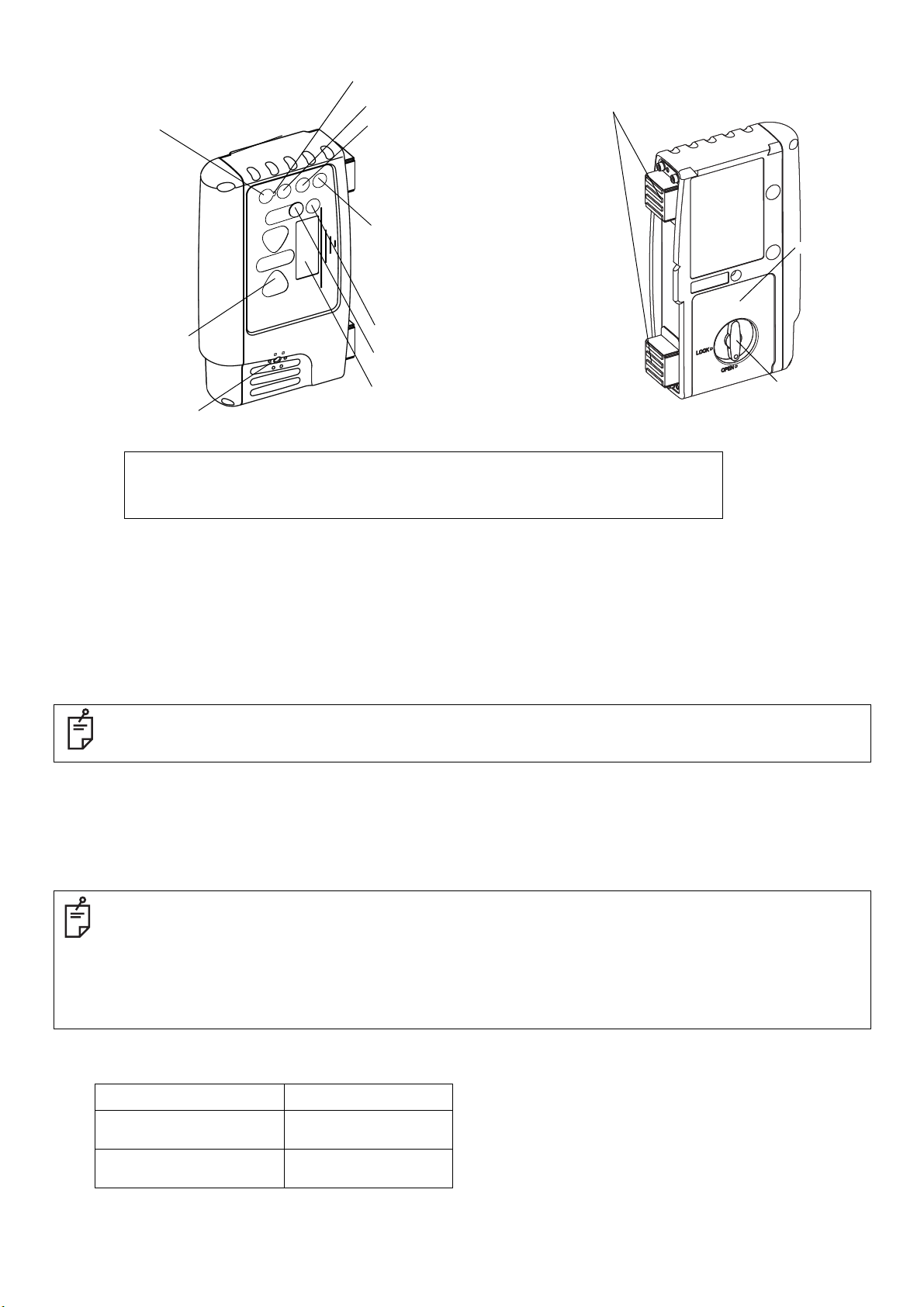
Nomenclature and Functions
Wireless communication switch
Communication ON/OFF: Short push
Communication default setting: Long push
Indicator(LED)
Buzzer speaker
Risk of damage to installation surface of machine, because it uses a strong magnet.
See [Laser beam positions and display patterns] in the Instruction manual for the display area and display pattern.
This instrument is able to perform wireless communication with the LS-B110W/LS-B10W, sold separately.
See the LS-B110W/LS-B10W Instruction manual for details on the LS-B110W/LS-B10W.
Wireless communication LED
Zero-set switch
Buzzer sound switch
Buzzer sound: Quiet/Loud/OFF:Short push
LED ON/OFF: Long push
Power switch
Power ON: Short push
Power OFF: Long push
LCD back light ON/OFF:
Short push when power is ON
(Auto turn-off after two minutes)
Detective precision (Mode) switch
Tilt switch
Indicator(LCD)
Magnet
Battery cover
Battery cover knob
How to set up the wireless communication default setting
Place the LS-B110W/LS-B10W and RD-100W in close position, so that they will not be affected by other wireless communications.
1 Turn on the power for both the LS-B110W/LS-B10W and RD-100W.
2 Long-push the wireless communication switch for the LS-B110W/LS-B10W and RD-100W. While setting up, the wireless communi-
cation LED (yellow light) will turn on.
3 When the instrument is ready to be used, a buzzer will sound (buzzer sound: peep) and the communication will begin.
• If the communication fails, a buzzer will sound (buzzer sound: pi, pi, pi). Eliminate any influence from other wireless instrument and redo
the communication default setting.
• While setting up the default, only the default OFF (short-push of the wireless communication switch) is operable.
How to use wireless communication
1 When power for both the LS-B110W/LS-B10W and RD-100W are turned ON, communication will automatically begin.
During communication, the wireless communication LED will flash quickly.
During communication preparation, the wireless communication LED will flash slowly
• When beginning the communication with LS-B110W, detective precision, tilt direction, tilt precision and ON-GRADE position setting will
be changed to the same setting as the
• When the detective precision, tilt direction, tilt precision or ON-GRADE position settings are changed while communicating with LSB110W, the setting for the
LS-B110W will also change in conjunction with the RD-100W.
• When begining the communication with LS-B10W, detective precision, buzzer sound, LED ON/OFF setting will be changed to the same
setting as the
LS-B10W.
• When the detective precision, buzzer sound or LED ON/OFF settings are changed while communicating with LS-B10W, the setting for
the
LS-B10W will also change in conjunction with the RD-100W.
• If you wish to change the
LS-B110W/LS-B10W to communicate, redo the communication default setting.
LS-B110W.
Lighting/Flashing pattern of wireless communication LED
Lights While setting up the default
Flashes quickly
Flashes slowly
While LS-B110W/LS-B10W is
communicating
Communication is in
preparation
Page 3

Indicator
Height alert warning of
rotating laser
A flash and a buzzer sound signifies
that the height alert function of rotating
laser is operating.
(This function is not usable to the rotating laser which does not have the height
alert and the function to output alarm
signal.)
Indicator(LED)
Flashes slowly
Rotating laser battery warning
A flash shows that the rotating laser power
is low.
(This function is not usable to the rotating
laser which does not have the function to
output alarm signal.)
Precision mode
Mode1
Higher than datum position
Move the sensor downward.
(Buzzer sound:High frequent beep sound)
Datum position (ON GRADE position)
(Buzzer sound:Continuous beep sound)
Lower than datum position
Mode2
Mode3
Mode4 (Blinking)
Move the sensor upward.
(Buzzer sound:Low frequent beep sound)
Battery remaining display
Indicates the battery remaining of remote display as follows.
Battery is sufficient.
Flashing alternately
The power is low, but remote display is still usable.
Dead battery.
Replace the dry battery with new one.
Auto-cut off function
The power will be turned off automatically after not communicating with LS-B110W/LS-B10W for more
than approx. 5 minutes.
(To turn on the power, press the power switch again.)
Laser beam positions and display patterns
During communication with LS-B110W
Indicator(LCD)
No display when in Mode 3 and 4
No display when in Mode 4
Indicator(LED)
Flashes quickly
Detective
precision
Mode1:±3mm
Mode2:±6mm
Mode3:±15mm
Mode4:±30mm
±15mm/±0.05ft
(30mm/0.1ft width)
±30mm/±0.1ft
(60mm/0.2ft width)
±50mm/±0.16ft
(100mm/0.33ft width)
±70mm/±0.23ft
(140mm/0.46ft width)
Laser beam positions and display patterns
During communication with LS-B10W
Indicator(LCD)
No display when in Mode 4
No display when in Mode 4
Indicator(LED)
Flashes quickly
Detective
precision
Mode1:±2mm
Mode2:±6mm
Mode3:±12mm
Mode4:±30mm
±15mm/±0.05ft
(30mm/0.1ft width)
±25mm/±0.08ft
(50mm/0.16ft width)
±35mm/±0.11ft
(70mm/0.23ft width)
Flashes slowly
Flashes more slowly
±125mm/±0.41ft
(250mm/0.82ft width)
When the laser beam is off
to the top or to the bottom
Flashes slowly
Flashes more slowly
±60mm/±0.2ft
(120mm/0.39ft width)
When the laser beam is off
to the top or to the bottom
Page 4

Tilt detection function (During communication with LS-B110W only)
Switching the tilt direction
The tilt direction can be changed.
1 Long-push the detective precision switch and the tilt switch at
the same time. The tilt direction mode setting changes in the
following order: "Back and Forth," "OFF" and "Right and Left."
At this time, the LED above the mark indicating the tilt direction
will flash. The LED will not flash when the tilt detection function
is switched OFF.
Tilt direction mark :
Back and Forth
Switching the tilt precision
Tilt direction mark :
Right and Left
1 Short-push the tilt switch. The tilt precision will change. At
this time, the LED below the mark indicating the tilt precision
will light up.
Tilt precision mark :
High precision
Tilt precision mark :
Normal precision
The LED lights up as shown in the figure for three seconds
when you have failed to change the ON-GRADE position. Be
careful not to change the position at which the laser beam is
detected and try setting once again.
The LED display and LCD display while changing the ONGRADE position
Flashes
The LED display indicating beam position and the
LED (1 green) in the center will flash. The mark
showing laser beam position on the LCD will flash.
Cancellation the ON-GRADE position change
1 Long-push the zero-set switch when not detecting the laser
beam. The ON-GRADE position will be reset.
When the ON-GRADE position change is cancelled,
the LED (3 green) will flash for three seconds.
Zero position setting for the tilt sensor
Before using the tilt detection function, set the zero position of the tilt
sensor according to the directions below. The tilt direction must be set
before setting the zero position.
1 Raise or lower the machine blade or arm where the LS-B110W
is installed to position the cutting edge or bucket at the desired
slope.
2 Long-push the tilt switch on RD-100W. The tilt angle for the
LS-B110W will set to 0°.
The LED (1 green) lights up as shown in the figure
for three seconds when the zero position is set.
The LED (2 red) flashes as shown in the figure for
three seconds when you have failed to set the
zero position.
Tilt angles and display patterns
Tilt directions : Right and Left
Flashes quickly
Flashes slowly
High precision
Normal precision
: ±1
°
: ±2.5°
±5
°
More than ±5°
FCC WARNING
Changes or modifications not expressly approved by the manufacturer for
compliance could void the user’s authority to operate the equipment.
In order to comply with FCC radio-frequency radiation exposure guidelines
for an uncontrolled exposure, this device and its antenna must not be colocated or operating in conjunction with any other antenna or transmitter.
This equipment complies with FCC/IC radiation exposure limits set forth for
uncontrolled equipment and meets the FCC radio frequency (RF) Exposure Guidelines in Supplement C to OET65 and RSS-102 of the IC radio
frequency (RF) Exposure rules. This equipment has very low levels of RF
energy that it is deemed to comply without testing of specific absorption
ratio (SAR).
This device complies with Part 15 of FCC Rules and RSS-Gen of IC Rules.
Operation is subject to the following two conditions : (1) this device may
not cause interference, and (2) this device must accept any interference,
including interference that may cause undesired operation of this device.
Specifications
Wireless communication
range
Power source : AA-size dry cells 3pcs.
Continuous operating time
(+20°C/+68°F)
Operating temperature : -20°C~+50°C(-4°F~+122°F)
Water proof : IP66 (Based on the standard IEC60529)
Dimensions (W/D/H) : 110x36x176(mm) (4.3″x1.4″x6.9″)
Weight (Without cells) : 0.5kg (1.2lbs)
:
20m
(May vary depending on obstacles between
the two instruments and other conditions)
:
Approximately 40 hours
(Using alkaline manganese dry cells)
Tilt directions : Back and Forth
High precision
Normal precision
High precision
Lights off
Tilt indication will be displayed during laser detection and for 20 seconds after switch
operation.
Normal precision
°
: ±1
: ±2.5°
: More than ±1
: More than ±2.5°
°
Changing the ON-GRADE position function
(During communication with LS-B110W only)
The ON-GRADE position can be changed to the position where laser
beam is detected. Using this function when installing the LS-B110W
on the pole of the machine allows easy setting of the height at which
the ON-GRADE will be displayed on the LS-B110W. The range in
which the ON-GRADE position can be changed is ±75mm (total of
150mm) from the center of the detective range.
1 Long-push the zero-set switch while detecting the laser beam.
When changing the ON-GRADE position, the LED lights up
for three seconds, as shown in the figure. The position where
the laser beam is being detected will be the ON-GRADE
position.
Detective angle, Detective precision and Laser detecting range may vary
depending on rotating laser being used or atmospheric conditions.
7400 National Drive, Livermore, CA 94551, U.S.A.
Phone: 925-245-8300 Fax: 925-245-8599 www.Topconpositioning.com
3380 Industrial Blvd, Suite 105, West Sacramento, CA 95691, U.S.A.
Phone: 916-374-8575 Fax: 916-374-8329
Essebaan 11, 2908 LJ Capelle a/d IJssel, The Netherlands.
Phone: 010-458-5077 Fax: 010-284-4941 www.topconeurope.com
Unit 69 Western Parkway Business Center
Lower Ballymount Road, Dublin 12, Lreland
Phone: 01460-0021 Fax: 01460-0129
Giesserallee 31, 47877 Willich, GERMANY
Phone: 02154-885-100 Fax: 02154-885-111 info@topcon.de
www.topcon.de
89, Rue de Paris, 92585 Clichy, Cedex, France.
Phone: 33-1-41069490 Fax: 33-1-47390251 topcon@topcon.fr
Phone: 031-7109200 Fax: 031-7109249
75-1 Hasunuma-cho, Itabashi-ku, Tokyo 174-8580, Japan
www.topcon.co.jp
Topcon House Kennet Side, Bone Lane, Newbury, Berkshire RG14 5PX U.K.
Phone: 44-1635-551120 Fax: 44-1635-551170
survey.sales@topcon.co.uk laser.sales@topcon.co.uk
Blk 192 Pandan Loop, #07-01 Pantech Industrial Complex, Singapore 128381
Phone: 65-6778-3456 Fax: 65-6773-6550 www.topcon.com.sg
77/162 Sinn Sathorn Tower, 37th Fl.,
Krungdhonburi Rd., Klongtonsai, Klongsarn, Bangkok 10600 Thailand.
Phone: 66-2-4401152~7 Fax: 66-2-4401158
No.D1, (Ground, Lower Ground & 1st Floor), Jalan Excella 2, Off Jalan Ampang
Putra, Taman Ampang Hilir, 55100 Kuala Lumpur, Malaysia
Phone: 60-3-42709866 Fax: 60-3-42709766
2F Yooseoung Bldg., 1595-3, Seocho-Dong, Seocho-gu, Seoul, 137-876, Korea.
Phone: 82-2-2055-0321 Fax: 82-2-2055-0319 www.topcon.co.kr
Block No.9, Kangding Street
Beijing Economic-Technological Development Area, Beijing, 100176, China
Phone: 86-10-6780-2799 Fax: 86-10-6780-2790
P. O Box293705, Office C-25(row C-2), Dubai Airport Free Zone, Dubai, UAE
Phone: 971-4-2995900 Fax: 971-4-2995901 marketing@Topcon.ae
31267 90111
6F
 Loading...