

Page 1
INSTRUCTION MANUAL
RC-40
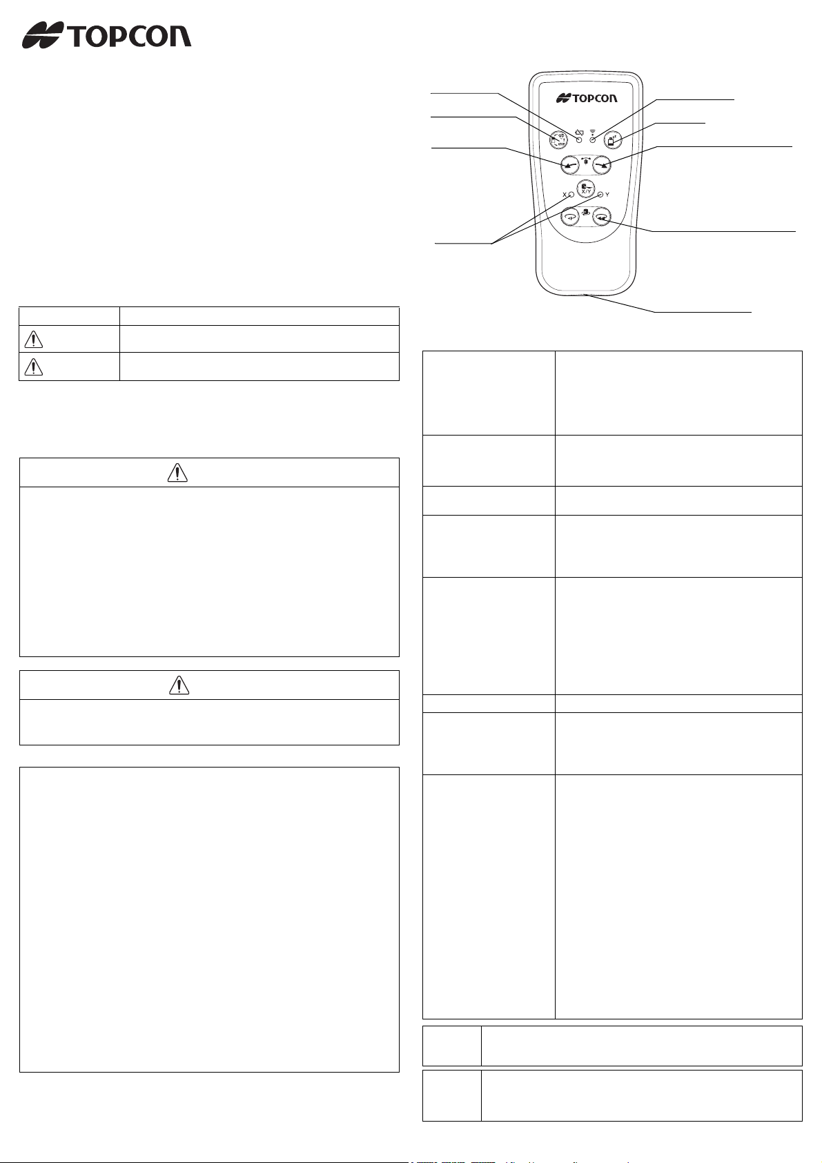
Battery warning
lamp for RC-40
Transmission lamp
Sleep Mode
X/Y axis lamp
Alignment control
Speed control
Mode switch control
Strap attachment hole
Slope mode / X/Y axis selection
When both the right and left keys
are pressed simultaneously, the
plumb beam mode will activate.
RC-40 Remote Controller
for RL-VH4DR/G2
Thank you for purchasing the TOPCON RC-40 Remote Controller.
For the best performance of the instruments, please read these
instructions carefully and keep them in a convenient location for
future reference.
DISPLAY FOR SAFE USE
In order to encourage the safe use of products and prevent any danger to
the operator and others or damage to properties, important warnings are
put on the products and inserted in the instruction manuals.
We suggest that everyone understand the meaning of the following displays
and icons before reading the “Safety Cautions” and text.
Display Meaning
WARNING
CAUTION
• Injury refers to hurt, burn, electric shock, etc.
• Physical damage refers to extensive damage to buildings or equipment and furniture.
SAFETY CAUTIONS
1) There is a risk of fire, electric shock or physical harm if you attempt to
disassemble or repair the instrument yourself.
This is only to be carried out by TOPCON or an authorized dealer, only!
2) Risk of fire or electric shock.
Do not use a wet battery or charger.
3) May ignite explosively.
Never use an instrument near flammable gas, liquid matter, and do not
use in a coal mine.
4) Battery can cause explosion or injury.
Do not dispose in fire or heat.
5) The short circuit of a battery can cause a fire.
Do not short circuit battery when storing it.
1) Do not allow skin or clothing to come into contact with acid from the batteries, if this does occur then wash off with copious amounts of water
and seek medical advice.
EXCEPTIONS FROM RESPONSIBILITY
1) The user of this product is expected to follow all operating instructions
and make periodic checks of the product’s performance.
2) The manufacturer, or its representatives, assumes no responsibility for
results of a faulty or intentional usage or misuse including any direct,
indirect, consequential damage, and loss of profits.
3) The manufacturer, or its representatives, assumes no responsibility for
consequential damage, and loss of profits by any disaster, (an earthquake, storms, floods etc.).
A fire, accident, or an act of a third party and/or a usage any other usual
conditions.
4) The manufacturer, or its representatives, assumes no responsibility for
any damage, and loss of profits due to a change of data, loss of data, an
interruption of business etc., caused by using the product or an unusable product.
5) The manufacturer, or its representatives, assumes no responsibility for
any damage, and loss of profits caused by usage except for explained
in the user manual.
6) The manufacturer, or its representatives, assumes no responsibility for
damage caused by wrong movement, or action due to connecting with
other products.
Ignoring or disregard of this display may lead to death or serious
injury.
Ignoring or disregard of this display may lead to personal injury
or physical damage to the instrument.
WARNING
CAUTION
NOMENCLATURE
FUNCTION DESCRIPTIONS
Sleep mode To set up (or cancel) the rotating laser to the sleep mode,
Transmission lamp This lamp will flash green when the signal is being trans-
Battery warning lamp for
RC-40
Speed control The rotation speed of the rotary head can be changed.
Alignment control
Vert ic al :
Setting line control
Horizontal :
Setting slope
X/Y axis lamp Indicates axis selected during beam sloping operation.
Mode switch control Laser mode is switched alternately as follows.
X/Y axis selection
Vert ic al :
Setting line control
Horizontal :
Setting slope
When you find it difficult to operate the remote controller, use it away
Note
Note
from the ground. (Radio transmission performance is lower near the
ground.)
With the RC-40, both the X and Y axes lamps will flash red simultaneously when more than one RC-40 or RL-VH4DR/G2 are used, and
also when similar wireless signals (wireless LAN, etc.) are being transmitted.
press the sleep mode key for three seconds or longer.
(In Sleep mode, the leveling lamp of the rotating laser
will flash.)
Laser turns off if standby mode continues for two hours.
(This mode cannot be used when the main power of the
rotating laser is OFF.)
mitted.
The lamp will flash red when an internal error has
occurred during transmission.
Battery warning for RC-40.
Replace the batteries with new ones when lit.
Pressing the left key will slow and pressing the right key
will accelerate the rotation speed.
When both the right and left keys are pressed simultaneously, the plumb beam mode will activate.
Performs line control during vertical rotation.
(Valid when the x or y axis is being selected with the x/y
axis selection key.)
Sets slope to the slope setting direction during horizontal
rotation.
(Valid when the x or y axis is being selected with the x/y
axis selection key.)
Scan mode / Laser sensor mode / Laser pointing mode.
If this key is pressed in other modes except Scan, Laser
sensor and Laser pointing modes, the mode will change
to scan mode.
Sets line control mode by pressing the key for more than
three seconds. Then X axis lamp will light.
Sets slope mode by pressing the key for more than three
seconds. Then X axis lamp will light. Lightly pressing
this key for short time will switchover the X and Y axis.
Press the alignment key when in the above rotation (vertical, horizontal), only then will the rotating laser switch to
the line control mode or the slope mode.
To cancel the line control mode or the slope mode, press
this key for more than three seconds.
When this key is pressed under the interference condition (several RC-40s or RL-VH4DR/G2 are using the
same channel), the X/Y axis red lamp will flash.
The X/Y axis red lamp will also blink simultaneously
when set up on a different channel or when RL-VH4DR/
G2 power is not on.
Page 2
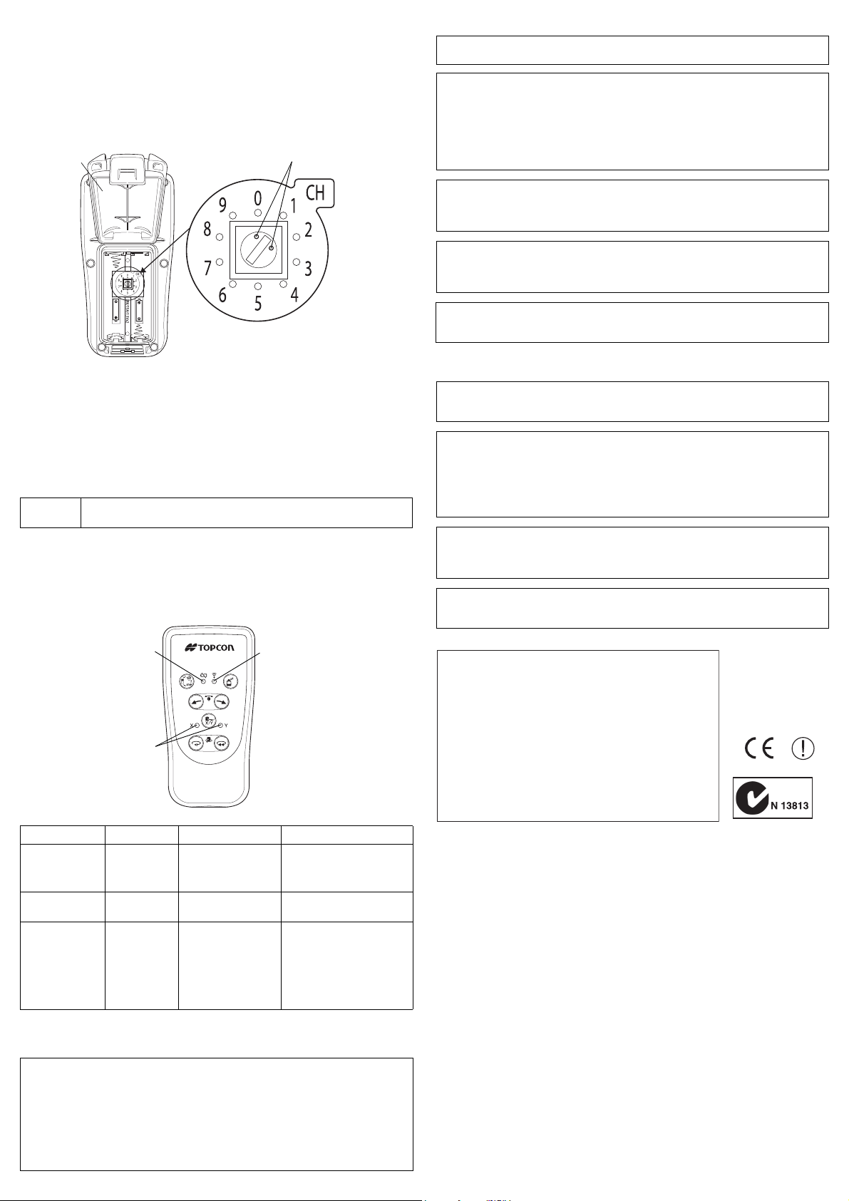
HOW TO SET COMMUNICATION CHANNEL
Channel switch (1 to 9)
Battery cover
Channel indicator mark
*
* The channel indicator mark indicates the
direction of the selected channel.
In the above figure, channel 1 is selected.
RC-40
A
B
C
Declaration of Confomity
R&TTE Directive 1995/5/EC
WE: TOPCON CORPORATION
75-1 Hasunuma-cho Itabashi-ku Tokyo Japan
declare on our own responsibility, that the product;
Kind of Product:
Remote Controller
Type designation: RC-40
is in compliance with the following norm(s) or documents;
Radio :EN 300 440-1, 2 EN 50371
EMC :EN 301 489-3
safety :EN 60950-1
The same communication channel (1 to 9) must be assigned to both the RC40 and the RL-VH4DR/G2.
FCC WARNING
Changes or modifications not expressly approved by the party responsible for compliance could void the user’s authority to operate the equipment.
1 Open the battery cover and remove the batteries.
2 Turn the channel switch to the same channel position set on the RL-VH4DR
/G2 by using a flat-head screwdriver. (Initial setting at shipping : Channel 1)
3 Insert batteries and close the battery cover.
HOW TO REPLACE THE RC-40 BATTERIES
1 Open the battery cover.
2 Remove the old batteries and replace with new 2xAA size dry cell batteries
(alkaline) making sure each is placed in the proper direction as indicated.
3 Shut the battery cover until click sound can be heard.
Note
• Replace all 2 batteries with new ones.
• Do not mix old batteries and new ones.
ERROR CODE
Use the tabel below to determine operation errors indicated by blinking
lamps on the control panel. If corrective action listed does not correct error,
please contact your local Topcon dealer.
Operation is subject to the following two conditions: (1) this device may not cause interference, and (2) this device must accept any interference received, including interference that may cause undesired operation of the device.
Lutilisation de ce dispositif est autorisée seulement aux conditions suivantes : (1) il ne
doit pas produire de brouillage et (2) l’utilisateur du dispositif doit être prêt à accepter
tout brouillage radioélectrique reçu, même si ce brouillage est susceptible de compromettre le fonctionnement du dispositif.
This device complies with Part 15 of the FCC Rules. Operation is subject to the following
two conditions: (1) this device may not cause harmful interference,
and (2) this device must accept any interference received, including interference that
may cause undesired operation.
CAUTION:This device and its antenna(s) must not be co-located or operating in
conjunction with any other antenna or transmitter. End user cannot
modify this transmitter device. Any unauthorized modification made on
the device could avoid the user's authority to operate this device.
The following sentence has to be displayed on the outside of the device in which the
transmitter module is installed:
“Contains FCC ID: H5PRF-01
IC WARNING
This Class B digital apparatus complies with Canadian ICES-003.
Cet apparei numérique de la class B est conforme à la norme NMB-003 du Canada.
The term “IC:” before the radio certification number only signifies that Industry Canada
technical specifications were met.
“Operation is subject to the following two conditions:
(1) this device may not cause interference, and
(2) this device must accept any interference, including interference that may cause
undesired operation of the device.”
“The installer of this radio equipment must ensure that the antenna is located or pointed
such that it does not emit RF field in excess of Health Canada limits for the general population; consult Safety Code 6, obtainable from Health Canada’s website www.hcsc.gc.ca/rpb”
The following sentence has to be displayed on the outside of the device in which the
transmitter module is installed:
“Contains IC: 6050A-RF01
Lamp Indication Error Code Cause Corrective Action
Remove and reinsert batteries
Lamp A red blinks Internal error Internal error
Lamp B blinks
Lamp C blinks
simultaneously
SPECIFICATIONS
Power supply : 2×AA size dry cell batteries (alkaline) DC 4.5 V
Operating time : Approx. 5 months (depends on the nature of use)
Operating temperature : -20°C to +50°C (-4°F to +122°F)
Dimensions : 116 (L) × 59 (W) × 31.4 (H) mm
Weight : 150 g (0.33 lbs)
Battery power
out error
Communication
error
Batteries depleted
Error in channel setting
Power not turned on
Channel interference
(4.6 (L) × 2.3 (W) × 1.2 (H) in)
once again.
If error repeats contact your
local Topcon dealer.
Replace all 2 batteries with
new ones at the same time.
Change the channel.
Turn on the power for RLVH4DR/G2.
If the error persists, check the
transmission environment and
reduce wireless LAN and
other similar wireless transmissions as much as possible.
31377 95020
 Loading...