

Page 1
INSTRUCTION MANUAL
REMOTE CONTROL SYSTEM 3
RC-3
Rev.1
Page 2

Page 3

Foreword
Foreword
Thank you for purchasing the Topcon RC-3 Remote control system-3.
For the best performance of the instrument, please read these brief instructions carefully, and
keep them in a convenient location for future reference.
This system has the following features:
• Enables optical communications between the total station GTS-900A, GPT-9000A and RC-3
on the prism side, which allows simplified one-man survey based on the application programs.
• Has the turn-round function with which more efficient one-man survey is possible.
General Handling Precautions
Before starting work or operation, be sure to check that this system is functioning correctly with
normal performance.
• Do not submerge the instrument into water.
The instrument can not be submerged underwater.
RC-3 is designed based on the International Standard IP65 and RC-3H is designed based on the
International Standard IP54, therefore it is protected from the normal rainfall.
• Guarding the instrument against shocks.
When transporting the instrument, provide some protection to minimize the risk of shocks. Heavy
shocks may cause the measurement to be faulty.
• Battery level check.
Confirm battery remaining level before operating.
• Storing the instrument for long period
Remove the battery from the instrument when you would not use it for long period.
• Turn-round motions and Optical communications
RC-3 should be kept aiming so that the total station always stays within the above range of
laser beam emission until the turn-round motions or optical communications are
completed.
If the aiming is out of above range while RC-3R is in turn-round motions or optical
communications, the turn-round or optical communications could not be completed.
See “Light emitting angle” on page 14 and “Light detecting range” on page 15.
1
Page 4
Safety Information
In order to encourage the safe use of products and prevent any danger to the operator and others
or damage to properties, important warnings are put on the products and inserted in the
instruction manuals.
We suggest that everyone understand the meaning of the following displays and icons before
reading the “Safety Cautions” and text.
Display Meaning
WARNING
Ignoring or disregard of this display may lead to death or serious injury.
Foreword
CAUTION
Injury refers to hurt, burn, electric shock, etc.
Physical damage refers to extensive damage to buildings or equipment and furniture.
Ignoring or disregard of this display may lead to personal injury or physical
damage to the instrument.
Safety Cautions
WARNING
• There is a risk of fire, electric shock or physical harm if you attempt to disassemble or repair the instrument yourself.
This is only to be carried out by TOPCON or an authorized dealer, only!
• Risk of fire or electric shock.
Do not use damaged power cable, plug and socket.
• Risk of fire or electric shock.
Do not use a wet battery or charger.
• May ignite explosively.
Never use an instrument near flammable gas, liquid matter, and do not use in a coal mine.
• Battery can cause explosion or injury.
Do not dispose in fire or heat.
• The short circuit of a battery can cause a fire.
Do not short circuit battery when storing it.
CAUTION
Use of controls or adjustment or performance of procedures other than those specified
herein may result in hazardous radiation exposure.
Do not allow skin or clothing to come into contact with acid from the batteries, if this does
occur then wash off with copious amounts of water and seek medical advice.
Risk of injury by falling down the instrument or case.
Do not use a carrying case with a damaged which belts, grips or latches.
It could be dangerous if the instrument falls over, please check that you fix the handle to
the instrument.
2
Page 5

User
1) This product is for professional use only!
The user is required to be a qualified surveyor or have a good knowledge of surveying, in
order to understand the user and safety instructions, before operating, inspecting or adjusting.
2) Wear the required protectors (safety shoes, helmet, etc.) when operating.
Exceptions from Responsibility
1) The user of this product is expected to follow all operating instructions and make periodic
checks of the product’s performance.
2) The manufacturer, or its representatives, assumes no responsibility for results of a faulty or
intentional usage or misuse including any direct, indirect, consequential damage, and loss of
profits.
3) The manufacturer, or its representatives, assumes no responsibility for consequential
damage, and loss of profits by any disaster, (an earthquake, storms, floods etc.).
A fire, accident, or an act of a third party and/or a usage any other usual conditions.
4) The manufacturer, or its representatives, assumes no responsibility for any damage, and loss
of profits due to a change of data, loss of data, an interruption of business etc., caused by
using the product or an unusable product.
5) The manufacturer, or its representatives, assumes no responsibility for any damage, and loss
of profits caused by usage except for explained in the user manual.
6) The manufacturer, or its representatives, assumes no responsibility for damage caused by
wrong movement, or action due to connecting with other products.
Foreword
Laser Safety
This product uses the invisible laser beam to communicate. This product is manufactured and
sold in accordance with “Performance Standards for Light-Emitting Products” (FDA/BRH 21 CFR
1040) or “Radiation Safety of Laser Products, Equipment Classification, Requirements and User’s
Guide” (IEC Publication 825) provided on the safety standards for laser beam.
As per the said standard, this product is classified as “Class 1 (I) Laser Products”.
This is simple a product to operating that is not required to training from a “Laser safety officer”.
In case of any failure, do not disassemble the instrument. Contact TOPCON or your TOPCON
dealer.
Class 1 Laser Product
Invisible Laser Beam
Total Station GTS-900A, GPT-9000A series
The software must be of the correct version for your version of the GTS-900A, GPT-9000A series,
otherwise the RC-3 will not function properly. Contact TOPCON or your TOPCON dealer for
version information.
3
Page 6

Contents
Foreword. . . . . . . . . . . . . . . . . . . . . . . . . . . . . . . . . . . . . . . . . . . . . . . . . . . . . 1
General Handling Precautions. . . . . . . . . . . . . . . . . . . . . . . . . . . . . . . . . . . . . . . . . . . . . . . . .1
Safety Information . . . . . . . . . . . . . . . . . . . . . . . . . . . . . . . . . . . . . . . . . . . . . . . . . . . . . . . . . .2
Safety Cautions . . . . . . . . . . . . . . . . . . . . . . . . . . . . . . . . . . . . . . . . . . . . . . . . . . . . . . . . . . . .2
User . . . . . . . . . . . . . . . . . . . . . . . . . . . . . . . . . . . . . . . . . . . . . . . . . . . . . . . . . . . . . . . . . . . . .3
Exceptions from Responsibility . . . . . . . . . . . . . . . . . . . . . . . . . . . . . . . . . . . . . . . . . . . . . . . .3
Laser Safety. . . . . . . . . . . . . . . . . . . . . . . . . . . . . . . . . . . . . . . . . . . . . . . . . . . . . . . . . . . . . . .3
Total Station GTS-900A, GPT-9000A series. . . . . . . . . . . . . . . . . . . . . . . . . . . . . . . . . . . . . .3
Contents . . . . . . . . . . . . . . . . . . . . . . . . . . . . . . . . . . . . . . . . . . . . . . . . . . . . . . . . . . . . . . . . .4
Nomenclature and Functions. . . . . . . . . . . . . . . . . . . . . . . . . . . . . . . . . . . . 5
Remote Controller RC-3R . . . . . . . . . . . . . . . . . . . . . . . . . . . . . . . . . . . . . . . . . . . . . . . . . . . .5
Remote Controller Handle Unit RC-3H . . . . . . . . . . . . . . . . . . . . . . . . . . . . . . . . . . . . . . . . . .7
Preparation . . . . . . . . . . . . . . . . . . . . . . . . . . . . . . . . . . . . . . . . . . . . . . . . . . 8
Battery installation and replacement . . . . . . . . . . . . . . . . . . . . . . . . . . . . . . . . . . . . . . . . . . . .8
Installing RC-3R onto the prism unit A6R . . . . . . . . . . . . . . . . . . . . . . . . . . . . . . . . . . . . . . . .9
Communication between the RC-3 and a data collector . . . . . . . . . . . . . . . . . . . . . . . . . . . .10
Mounting remote controller handle unit RC-3H onto the total station . . . . . . . . . . . . . . . . . .10
Basic Operation. . . . . . . . . . . . . . . . . . . . . . . . . . . . . . . . . . . . . . . . . . . . . . 11
Power switch ON . . . . . . . . . . . . . . . . . . . . . . . . . . . . . . . . . . . . . . . . . . . . . . . . . . . . . . . . . .11
Battery Remaining Display . . . . . . . . . . . . . . . . . . . . . . . . . . . . . . . . . . . . . . . . . . . . . . . . . .11
Battery Warning Display for RC-3R. . . . . . . . . . . . . . . . . . . . . . . . . . . . . . . . . . . . . . . . . . . .11
Battery Warning for GTS-900A, GPT-9000A series . . . . . . . . . . . . . . . . . . . . . . . . . . . . . . .11
Auto Power Off . . . . . . . . . . . . . . . . . . . . . . . . . . . . . . . . . . . . . . . . . . . . . . . . . . . . . . . . . . .11
Error display. . . . . . . . . . . . . . . . . . . . . . . . . . . . . . . . . . . . . . . . . . . . . . . . . . . . . . . . . . . . . .11
Setting for Optical communications with total station . . . . . . . . . . . . . . . . . . . . . . . . . . . . . .12
Table of item to be set . . . . . . . . . . . . . . . . . . . . . . . . . . . . . . . . . . . . . . . . . . . . . . . . . . . . . .13
Light emitting angle . . . . . . . . . . . . . . . . . . . . . . . . . . . . . . . . . . . . . . . . . . . . . . . . . . . . . . . .14
Light detecting range . . . . . . . . . . . . . . . . . . . . . . . . . . . . . . . . . . . . . . . . . . . . . . . . . . . . . . .15
Turn-round function . . . . . . . . . . . . . . . . . . . . . . . . . . . . . . . . . . . . . . . . . . . . . . . . . . . . . . . .16
Stopping turn-around operations . . . . . . . . . . . . . . . . . . . . . . . . . . . . . . . . . . . . . . . . . . . . . .17
Low Power mode of Laser Beam. . . . . . . . . . . . . . . . . . . . . . . . . . . . . . . . . . . . . . . . . . . . . .17
Reference : Turn-round motions:. . . . . . . . . . . . . . . . . . . . . . . . . . . . . . . . . . . . . . . . . . . . . .17
Setting Mode . . . . . . . . . . . . . . . . . . . . . . . . . . . . . . . . . . . . . . . . . . . . . . . . 18
Setting Items . . . . . . . . . . . . . . . . . . . . . . . . . . . . . . . . . . . . . . . . . . . . . . . . . . . . . . . . . . . . .18
How to Set . . . . . . . . . . . . . . . . . . . . . . . . . . . . . . . . . . . . . . . . . . . . . . . . . . . . . . . . . . . . . . .18
Communication Baud Rate . . . . . . . . . . . . . . . . . . . . . . . . . . . . . . . . . . . . . . . . . . . . . . . . . .19
Power Source and Charging . . . . . . . . . . . . . . . . . . . . . . . . . . . . . . . . . . . 20
Special Accessories . . . . . . . . . . . . . . . . . . . . . . . . . . . . . . . . . . . . . . . . . . 21
Precaution . . . . . . . . . . . . . . . . . . . . . . . . . . . . . . . . . . . . . . . . . . . . . . . . . . 22
Specifications . . . . . . . . . . . . . . . . . . . . . . . . . . . . . . . . . . . . . . . . . . . . . . . 23
Foreword
4
Page 7
Nomenclature and Functions
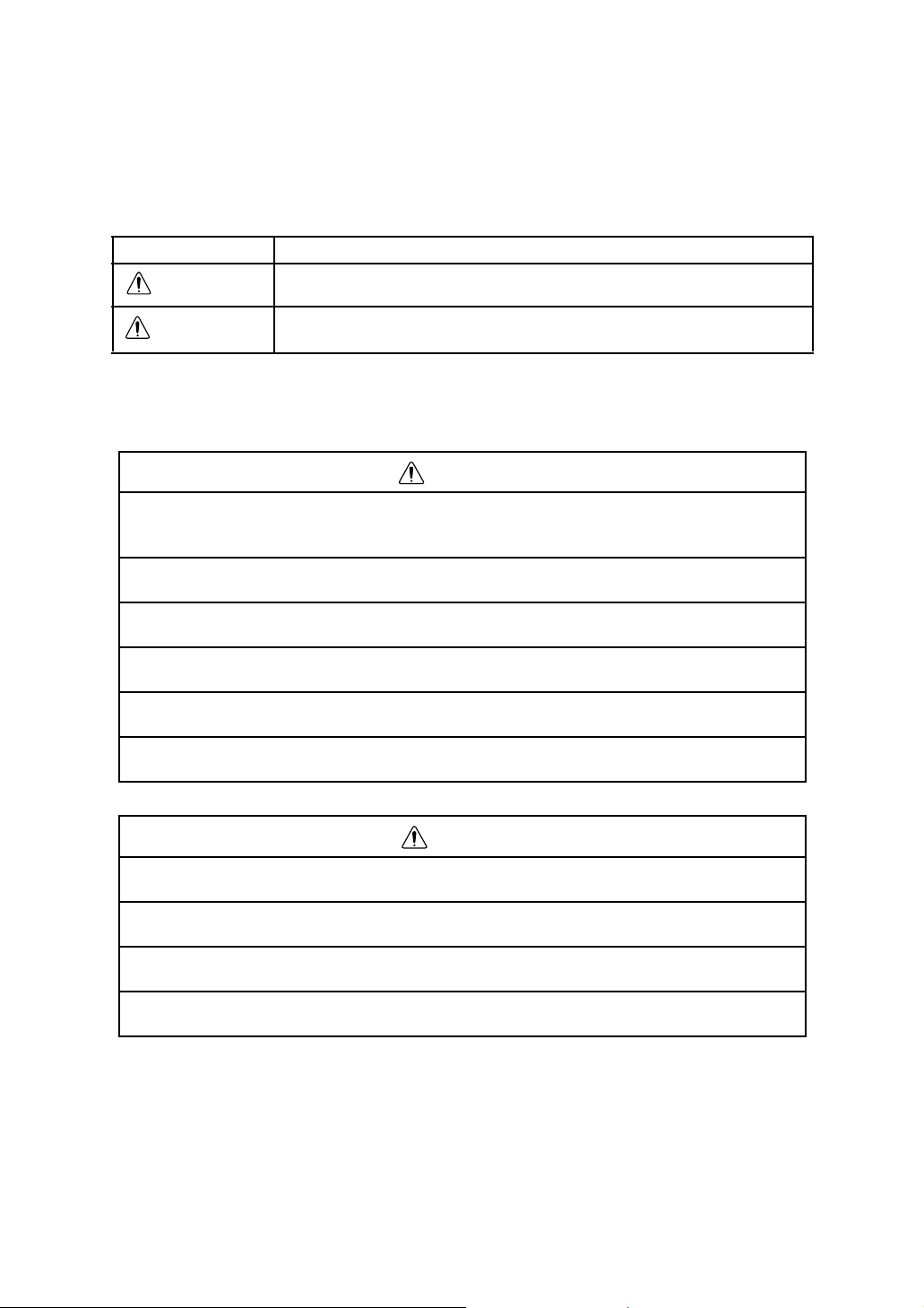
Remote Controller RC-3R
Receiving window
Emitting window
(Laser beam aperture)
Nomenclature and Functions
Operating keys
DM pole
Serial signal
RS-232C
connector
Rear side
Prism unit A6R
(Optional accessory)
Bottom
Hook for holder
battery cover
unhooking lug
Battery cover
5
Page 8

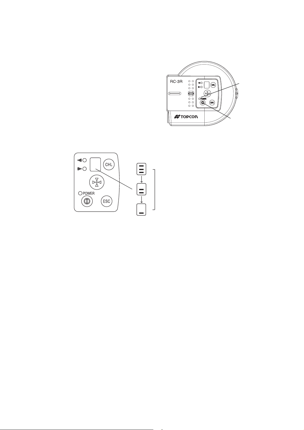
Panel
Nomenclature and Functions
Channel display / Battery remaining display
Receiving LED
Sending LED
Power LED
Power switch
Key Function
Power switch ON/OFF of power of the RC-3R.
Turn-round key Total station will be in turn-round motion.
Escape key
Channel key Sets up channels for optical communication.
Cancels the emitting laser for turn-round motion. The total station will
stop the turn-round operation after continuing the motion for a while.
LEDs
Channel key
Turn-round key
Escape key
LED Status Contents
Power
LED
Receiving
LED
Sending
LED
On solid The power of RC-3R is ON.
Flash The battery remaining of RC-3 is low.
The battery should be recharged or replaced with a fully
charged battery.
Off The power is OFF
On solid
On solid RC-3R is in the middle of data transmission.
Flash RC-3R is in the middle of turn-round command transmission.
RC-3R is in the middle of data reception.
6
Page 9
Nomenclature and Functions
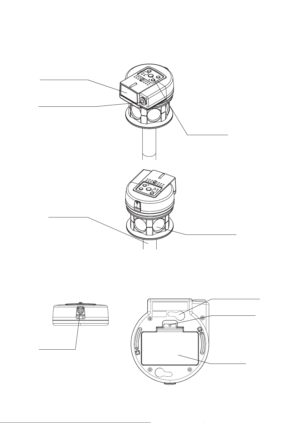
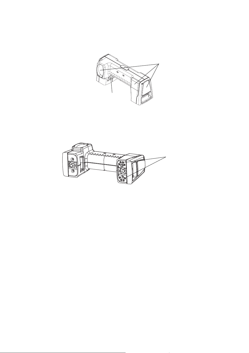
Remote Controller Handle Unit RC-3H
GTS-900A, GPT-9000A series total station requires RC-3H to enable turn-round motions and
optical communications with RC-3H.
RC-3H
Detectors
(at five points)
Fixing knob
GTS-900A, GPT-9000A series carrying case is large enough to house the total station fitted with
RC-3H.
Connection points
Do not damage or shock connection points. It may cause malfunction.
7
Page 10
Preparation
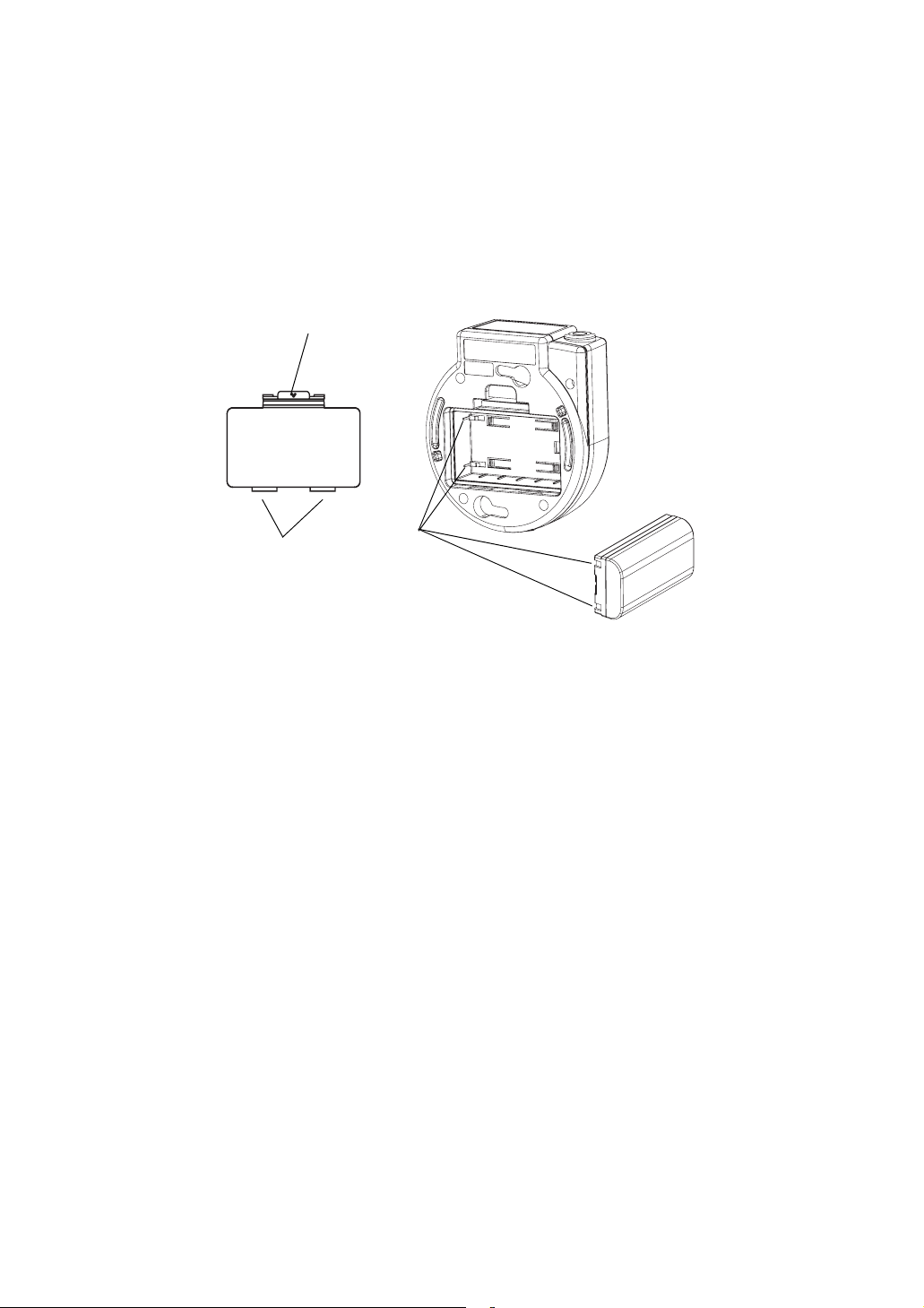
Battery installation and replacement
Push up and unhook the battery cover lug and remove the cover.
1
Insert Battery BT-62Q in the direction matching connection points as shown in the illustration.
2
Push the battery cover lug down until the cover is locked.
3
Battery cover lug
Battery cover
Connection
Lug
points
Preparation
8
Page 11

Installing RC-3R onto the prism unit A6R
Match the receiving window with the front mark and insert the mounting hooks on the Prism
1
Unit A6R into the mounting holes of the RC-3R.
Mounting hooks
Front mark
Turn the RC-3R towards the front mark (until you hear a click).
2
Preparation
Mounting
holes
9
Page 12

Preparation
Communication between the RC-3 and a data collector
• For communicating between the data collector and the RC-3R by means of Bluetooth.
• For communicating between the data collector and the RC-3R by means of an RS-232C
connector, connect the cable to the RC-3’s RS-232C connector.
Mounting remote controller handle unit RC-3H onto the total station
Optical communications between total station and RC-3R, become possible by installing remote
controller handle unit RC-3H onto the total station.
Dismount the handle from total station.
1
RC-3H
Handle
Handle unit
mounting mark
Match the handle unit mounting marks for the RC-3H and total station.
2
Make sure that the fixing knob is tightly fastened.
3
Note
• Ensure that the power switch of total station is off when mounting RC-3H.
10
Page 13
Basic Operation
Power switch ON
Press the power switch.
Power LED will light.
Power switch
Battery Remaining Display
Push [ESC] key and the battery remaining capacity will be displayed for approximately 5 seconds.
Battery remaining display
Usable
Basic Operation
Power LED
Battery Warning Display for RC-3R
When the battery of the RC-3R is low, the power LED will flash with beep sound.
(Audio sound: Two pitches, frequent beep synchronized with power LED)
Confirm the battery remaining when turning on the instrument.
When the LED is displayed and the beep sounds, replace or recharge the battery.
Battery Warning for GTS-900A, GPT-9000A series
When the battery power of total station in optical communication with RC-3R is low, the beep will
sound from the RC-3R.
(Audio sound: Three pitches, frequent beep)
When the beep sounds, replace or recharge the batteries of total station.
Auto Power Off
If no key operation is given or no communication is performed for more than 30 minutes, the
power turns off automatically.
Error display
The RC-3R unit does not display errors.
Refer to the operation manual for the data collector and other software for details.
11
Page 14

Setting for Optical communications with total station
The following settings is prerequisites for the optical communications to take place between the
total station (or an application program) and RC-3R.
Setting Parameters in total station
• When communicating by using [EXT.LINK] of the application software
(AP-L1 communication mode).
Set Parameter for RC.
1
Operation:
Main menu - Program Modes (Prog) - (EXT.LINK) - (Setting) - (RC)
Execute the External Link.
2
Operation:
Main menu - Program Modes (Prog) - (EXT.LINK) - (Execute)
• When communicating without using [EXT.LINK] (GTS communication
mode).
Set the parameters in the Parameters Setting Mode. (Refer to Table of item to be set shown
1
as follows.)
Operation:
Main menu - Parameters Setting Modes (SETUP) - (communication) - (RC)
Execute the Standard Measurement Mode.
2
Main menu-Standard Measurement Mode (Meas)
Basic Operation
Setting Parameters in RC-3R
Set the parameters in Setting Mode.
Refer to Table of item to be set in Setting Mode.
Setting Parameters of Communication port in Data Collector
Connect a data collector to be used to the serial RS-232C connector of the RC-3R, and set the
items as follows.
B.Rate
Data.L
Parity
Stop Bit
9600
8
none
1
12
Page 15

Table of item to be set
Following parameters surrounded that you must set for RC-3R and total station.
• Setting Parameters in total station
Operation Item
Main menu
|
Prog
|
EXT.LINK
Main menu
Setting PARAMETER(RC)
RC Select
REC TYPE Select
Terminate Select
Channel
|
Setup
|
Com.
RC
V.Search Select Select
RC Select Select
CR, LF
The content of each set item of "EXT.LINK" is the following.
Moreover, please refer to the total station's manual for Parameters.
By using "EXT.LINK"
(AP-L1 communication
mode)
Matches the communication
channel to RC-3R.
Basic Operation
Setting
Without using "EXT.LINK"
(GTS communication
mode)
Select
Select
Channel 1/2/3/4/5/6
Terminate ETX / ETX+CR / ETX+CR+LF
REC TYPE REC-A /REC-B
• Setting Parameters in RC-3R
Communication channel Select
RS-232C Baud rate Select
Refer to "Setting Mode".
Select the option OFF or ON for carriage return and line feed
when collecting measurement data with a data collector.
Select the option to record the data.
REC-A: The measurement is started and new data is output.
REC-B: The data memorized in total station is output.
13
Page 16

Light emitting angle
Laser beams are emitted from the emitting window of the RC-3R.
The angle of emitting laser beams is as follows.
Light emitting angle
Basic Operation
Top view
Light emitting angle
At greater distances, the laser light at
the edge of the beam field (angle) will
be weaker.
• RC-3R should be kept aiming so that the total station always stays within the
above range of laser beam emission until the turn-round motions or optical
Important
communications are completed.
If the aiming is out of above range while RC-3R is in turn-round motions or
optical communications, the turn-round or optical communications could not be
completed.
Side view
14
Page 17

Light detecting range
The detecting angles of RC-3R and RC-3H (Total station) are shown below:
Total station can only be turned round with the turn-round key under the condition that RC-3R
remains confined within the range as shown below where RC-3H can detect light.
RC-3R should be aimed in a way to always capture the total station within this range during
receiving data from the total station.
Detecting range
(RC-3H can detect the laser in all
horizontal direction.)
RC-3H
Detecting range
Top view
Side view
Basic Operation
Turn-round function can be
done within above range.
Important
•
The RC-3R must be aimed so as to
capture the total station within
above range during communicating.
15
Page 18

Turn-round function
• RC-3R should be kept aiming so that the total station always stays within the
above range of laser beam emission until the turn-round motions is completed.
Important
The turn-round key on RC-3R is used to have the total station search or automatically track RC3R (prism).
In the auto tracking mode, RC-3R and the total station are ready for optical communications.
Turn-round function is useful for auto-tracking when you start working or when the auto-tracking is
interrupted by any reason.
For increasing efficiency, keep the auto-tracking status when you move to another measurement
point.
If the aiming is out of above range while RC-3R is in turn-round motions, the turnround could not be completed.
• At greater distances, the laser light at the edge of the emitting range (angle) will
be weaker; therefore, the RC-3R must be aimed correctly.
Basic Operation
Note
Turn on the total station and execute the [External Link].
1
Aim the RC-3R light emitter at the total station.
2
Turn On the RC-3R by pressing the power switch.
3
Press the [turn-round] key on RC-3R.
4
• The settings and conditions of communication are prerequisites for the optical
communications to take place between the total station and RC-3R.
Total station starts searching and ends in the tracking mode where it is communicable with
this system.
• Total station must be kept apart from reflecting planes such as glass
and white walls. Reflected light may prevent it from correct prism
searching and from auto tracking. In this case, change the power mode
of RC-3R to the low power mode to decrease the output of laser beam.
To change the power mode, see “Low Power mode of Laser Beam” on
Note
page 17.
• Ensure that RC-3R remains as motionless as possible when the total
station is in turn-round motions. Total station otherwise may not be able
to search prism correctly, requiring extra time for the task.
• The RC-3R must be aimed so as to capture the total station within a
range of ± 35° in the vertical and horizontal direction during
communicating. (Refer to “Light detecting range” section.)
16
Page 19

Stopping turn-around operations
Press the [ESC] key to terminate turn-around operation. After the key is pressed, turn-around
operation will continue for a short time before the Total Station comes to a stop.
Low Power mode of Laser Beam
When the Total Station performs a turn-around function at a distance of approximately 10 m from
the RC-3R, strong reflections of the pulsed laser diode (PLD) emission can prevent the Total
Station from searching the prism correctly. In this case, switch the laser to low-power mode to
reduce the intensity of such reflections.
In low-power mode, the range of the turn-round function is shorter than in normal-power mode.
To change the low-power mode
Turn the power ON while holding down the [ESC] key.
A buzzer will sound indicating that the RC-3R is in low-power mode.
To return to normal-power mode, turn the power OFF, wait several seconds, and then turn the
power ON again.
Reference : Turn-round motions:
When the turn-around key on the RC-3R is pressed, the pulsed laser diode (PLD) in the emitter
produces a laser beam with a ± 5° cone pattern (Refer to “Light emitting angle” on page 14”.)
The RC-3H component of the Total Station has photo detectors on all four sides (front, rear, right
and left), allowing laser beams to be detected in any orientation. This detection ability extends to
approximately ± 30° in the vertical direction (refer to “Light detecting range” on page 15.)
Upon detecting laser emissions, the Total Station aligns toward the RC-3R.
After horizontal alignment, the telescope is scanned vertically in order to target the prism and
initiate auto tracking.
Basic Operation
Under certain conditions, the time required for communications can increase to the point
that turn-around operations require a long time to complete, and under certain
circumstances such operations might not even be completed properly. The following
conditions can adversely affect operation:
1) When units are used for communication over long distances or under poor atmospheric
and weather conditions (e.g., in strong direct sunlight; heat refraction such as occurs
near road surfaces and building surfaces on hot days; rain; fog, etc.)
2) When the aim of the RC-3R is set incorrectly (refer to “Light emitting angle” on page 14.)
3) When the installation position of the prism and RC-3R are separated (refer to “Setting
Mode” on page 18.)
4) When communication channel settings, or other settings, of the total station and RC-3R
are not matched or are set incorrectly (refer to “Table of item to be set” on page 13 and
“Setting Mode” on page 18.)
5) When the total station is located in front of or to the side of glass or some other reflective
surface.
6) When, during turn-around operations, a person, car, or other object obstructs the light
path between the total station and the RC-3R.
7) When the units are used over long distances, the RC-3R is set to low-power mode
(“Low Power mode of Laser Beam” on page 17.)
8) When the dip switch settings on the RC-3R are set incorrectly (refer to “Setting Mode”
on page 18.)
9) When the battery status display on the total station is flashing (low battery power)
17
Page 20

Setting Mode
In this mode, following items can be set.
Setting Items
Items Selecting item Description
Optical
communication
channel
Communication
baud rate
How to Set
Remote control channel
With the power ON, push the channel change key on the panel once.
1
Current channel will be displayed (Default setting: 1)
While the channel is displayed (approx. 5 seconds), push the key once again.
2
It will switch to the next channel.
Repeat step 2 until the channel you wish to set is displayed.
3
(The optical communication channel setting cannot be changed during turn-round.)
1 to 6
9600/4800
Setting Mode
Sets a channel to be used for communications. The
same communication channel must be assigned to
both RC-3R and the total station.
Prevents interference of communication when several
systems consisting of a total station and a RC-3 are
used at one site.
Select communication speed.
18
Page 21

Communication Baud Rate
Setting can be done with the dip-switch on the battery section.
Remove battery cover and batteries.
1
Set by pressing the dip-switch with a pin.
2
Battery cover
unhooking lever
Setting Mode
Battery cover
Note
Dip-switch
Dip-switch Setting Contents
Serial signal RS-232C
baud rate setting
Unused (fixed to OFF)
Unused (fixed to OFF)
Unused (fixed to OFF)
• Dip-switch No.2-4 must be fixed to OFF position.
The RC-3R does not work correctly when the switch No.2-4 are set to
ON position.
1
2 Unused (fixed to OFF) -----
3 Unused (fixed to OFF) -----
4 Unused (fixed to OFF) -----
OFF 9600
ON 4800
19
Page 22

Power Source and Charging
Power Source and Charging
CHARGE LED
BC-30
Connect the AC-Cable to the charger.
1
Plug the AC-Plug into the outlet. (The POWER LED will light.)
2
Attach the battery in the charger. Charging will start. (The CHARGE LED will light.)
3
POWER LED
BT-62Q
AC-cable
Charging will take approximately 4 hours. (The CHARGE LED will go out.)
If battery power is at a very low level when beginning charging, such as after the instrument
has been in storage over an extended period of time in a discharge state, a full charge may
not be possible with a single charging. In such a case, recharge a second time.
After charging, remove the battery from the charger.
4
Remove the charger from the outlet.
The POWER LED
Red ON : Power is on.
The CHARGE LED will indicate charging status;
On Solid : Wait for charging.
Red ON : Charging.
On Solid : Charging completed.
Red Flashing: Charging error.
CHARGE LED will flash when the battery life is over or the battery is broken down. Replace the
battery to new one.
• When CHARGE LED flashes, reinstall the battery or re-plug the outlet of the charger. If CHARGE
LED still continues to flash, there may be breakdown of the battery or the charger. Stop charging
immediately, unplug the charger and contact the distributor.
• Do not charge or discharge continuously, otherwise the battery and the charger may be
deteriorated.
If charging is necessary, use the charger after stopping charge for approximately 30 minutes.
• Do not charge the battery or discharge the battery in right after the battery is charged, it causes
deterioration of the battery in rare cases.
• The charger may develop heat while charging, there is no problem of it.
• Recharging should take place in a room with an ambient temperature range of 10°C to 40°C (50°F
to 104°F).
• Exceeding the specified charging time may shorten the life of the battery and should be avoided if
possible.
• The battery source will discharge when stored and should be checked before using with
instrument.
• If the instrument is not used over an extended period of time, store in a place at 30°C or below in
a 50% charged state.
Over discharge will lower performance and a full charge may become impossible. Please charge
once every few months.
20
Page 23

Special Accessories
Special Accessories
Data Collector
Suitable for systemization of measuring
instrument. Measuring data will be
automatically stored and transferred to a
computer system, making measuring
operations more efficient and saving time and
effort in such operation.
RC-3R
Prism unit-A6R/A6S
21
Page 24

Precaution
• Always clean the instrument after use.
• Remove the dust using a brush, then wipe off with a soft cloth.
For cleaning the lens surface of the receiving window, use a cleaning brush, then use a clean
lintless cotton cloth. Moisten it with alcohol (or mixture with ether) to wipe gently in a rotational
motion from the center out.
• To remove the dust on the surface of emitting window or the parts made by plastic, never use
thinner or benzine. Use a clean cloth moistened with neutral detergent.
• Always make sure the instrument is completely dry before storing. Dry any moisture with a
soft, clean cloth.
Precaution
22
Page 25

Specifications
Operating temperature : -20°C to +50°C
Storing temperature : -30°C to +60°C
Protection against water
and dust : RC-3R: IP65
RC-3H: IP54 (Based on the standard IEC60529)
Operating distance * 1) : 5m~400 m (16ft ~1310 ft)
(When using with the prism unit A6R/A6S)
* 1) The operating distance may be shorter than normal in such the
condition is not good by the heat simmer or strong direct sun
shine to the detector.
Turn-round operating
time : Approximately 10 seconds *2, 3)
Optical communicating
time : Approximately 3 to 4 seconds *2, 4)
* 2) Sight haze with visibility about 20km (12.5 miles) moderate
sunlight with light shimmer.
* 3) Under normal weather conditions, with the telescope turned
90° relative to the prism, and turn-around performed with the
prism roughly aligned vertical. (refer to “Reference : Turnround motions:” on page 17.)
* 4) Standard times for data display and data recording. Times may
vary depending on software version.
Number of optical
communication channels : 6
Specifications
Remote Controller Handle Unit RC-3H
Power source : DC 7.4V from total station
Detective range : Horizontal : 360°
Vertical : ±30°
Weight : 0.3 kg
Dimensions : 58(D) × 166(W) × 71(H) mm
Remote Controller RC-3R
Weight : 0.3 kg
Dimensions : 122 (D)× 110 (W)× 46 (H) mm
Bluetooth™ Unit
Bluetooth™ Standard
Bluetooth™ profiles
BD Address
Bluetooth™ Transmitting
Bluetooth™
Communication distance
Bluetooth™ Specification v1.2
:
Generic Access Profile
:
Service Discovery Application Profile
:
Serial Port Profile
:
IEEE std802 48bit LAN MAC Address
:
Output Class2
:
About 5m
:
(The range will be different by a condition)
23
Page 26

[Emitting Laser]
Angle of Laser : Each direction ±5°
At greater distances, the laser light at the edge of the emitting
range (angle) will be weaker by laser emitting characteristic.
100m (328ft): Approximately
400m (1310ft): Approximately
±5°
±3°
Laser class : Class 1/ Class l
[Detecting Laser]
Detecting range : Horizontal ±35°
Vertical ±35°
[Interface]
Connector with 6 pins : RS-232C
Baudrate: 9600/4800
Bit length: 8 bits
Parity bit: None
Stop bit: 1 bit
Rechargeable Battery BT-62Q
Output voltage : DC7.4V
Capacity : 2200mAh
Maximum operating time : 20hours *1)
*1) Normal use Under normal temperature at +20°C, Measuring two points (In-
cluding communicating and recording data) every 1 minute
and using turn-around function once every 10 minutes.
In low temperature, operating time will decrease rapidly due to
the characteristic of battery.
Specifications
24
Page 27

Bluetooth™ and the Bluetooth™ logos are trademarks owned by Bluetooth™ SIG, Inc., USA and licensed to Topcon
Corporation.
Page 28

TOPCON CORPORATION
7
P
jp
5-1 Hasunuma-cho, Itabashi-ku, Tokyo 174-8580, Japan
hone: 3-3558-2520 Fax: 3-3960-4214 www.topcon.co.
©2006 TOPCON CORPORATION
ALL RIGHTS RESERVED
 Loading...