

Page 1
0OCKET$
2EFERENCE'UIDE
Page 2

Page 3

POSITIONING SYSTEMS
Pocket-3D
Reference Guide
Part Number 7010-0628
Rev J
©Copyright Topcon Positioning Systems, Inc.
February 2012
All contents in this manual are copyrighted by Topcon. All rights reserved.
The information contained herein may not be used, accessed, copied, stored,
displayed, sold, modified, published, or distributed, or otherwise reproduced
without express written consent from Topcon.
Page 4

ECO#000061
Page 5

TOC
Table of Contents
Preface .................................................................. iii
What’s New with Pocket-3D ................................ ix
Chapter 1
Installing Pocket-3D ............................................. 1-1
Guide to Installing Pocket-3D ......................................... 1-2
Starting Pocket-3D ........................................................... 1-5
Main Screen ..................................................................... 1-6
Context (Pop-Up) Menu Options ....................... 1-9
Toolbar ............................................................................. 1-12
Menu Bar ......................................................................... 1-13
Pocket-3D Technical Information ................................... 1-16
GPS Status Information ................................................... 1-17
GPS Status ................................................................. 1-17
Monitor GPS Status Information ........................ 1-18
View the Receiver’s Current Position ................ 1-18
Monitor Satellites and Enter the Mask ............... 1-19
View Receiver Information or Reset Receiver ... 1-19
View PDOP Values ............................................ 1-20
Apply GPS Receiver Settings ............................. 1-20
Total Station Status ................................................... 1-21
Monitor Prism Position Information ................... 1-22
Set Total Station Search Parameters ................... 1-22
Set Total Station Tracking Sensitivity and Speed 1-23
Chapter 2
Setup Menu ........................................................... 2-1
GPS Applications ............................................................. 2-1
Equipment ................................................................. 2-2
Radios ........................................................................ 2-6
Antenna ..................................................................... 2-7
P/N 7010-0628
i
Page 6

Table of Contents
Base Station ............................................................... 2-8
Units ........................................................................... 2-11
Exit ............................................................................. 2-12
Equipment Configuration Files ........................................ 2-13
Sample Configuration 1: Range-pole with
HiPer Lite Receiver ................................................ 2-13
mmGPS Applications ....................................................... 2-18
Equipment .................................................................. 2-19
mmGPS Transmitters ................................................. 2-19
TX Calibration .................................................... 2-21
Edit Channel ........................................................ 2-23
Benchmark Check ............................................... 2-24
Resection ............................................................. 2-25
mmGPS Receiver ....................................................... 2-27
Total Station Applications ................................................ 2-29
Equipment .................................................................. 2-29
Range-pole ................................................................. 2-31
Sample Configuration 4: Prism and Total Station ..... 2-32
Robotic Applications ........................................................ 2-35
Equipment ........................................................................ 2-36
Station Setup .................................................................... 2-38
SiteLink® 3D for Pocket-3D ........................................... 2-44
The Site-Link Network Connection ........................... 2-45
Connecting to SiteLink-3D .............................................. 2-46
Selecting the Current Operator .................................. 2-47
Managing Activities/Delays ...................................... 2-47
Sending, Viewing, and Deleting Messages ............... 2-48
Send Any File to the Jobsite ...................................... 2-50
Exporting a Project File Via Site-Link ...................... 2-51
Importing/Exporting Control Points Via Site-Link .......... 2-54
Importing/Exporting Surface Files Via Site-Link ............ 2-57
Importing/Exporting Alignment Files Via Site-Link ....... 2-59
Importing/Exporting Linework Files Via Site-Link ......... 2-61
Importing/Exporting Points Via Site-Link ....................... 2-63
Chapter 3
Data Menu ............................................................. 3-1
Project ............................................................................... 3-2
ii
Pocket-3D Reference Guide
Page 7

Table of Contents
Import/Export ............................................................ 3-4
Control ............................................................................. 3-13
Control Points ............................................................ 3-13
Import/Export ............................................................ 3-16
From Text File .................................................... 3-17
Conversion Formats ............................................ 3-18
Control Point Options ............................................... 3-21
Surface ............................................................................. 3-24
Current File or <none> .............................................. 3-25
TIN Surface File ................................................. 3-26
Road Surface File ............................................... 3-28
Plane Surface File ............................................... 3-39
Best-fit Plane Surface File .................................. 3-40
Compare Surface ....................................................... 3-42
Surface Options ......................................................... 3-45
Alignment ........................................................................ 3-47
Current File or <none> .............................................. 3-49
New ..................................................................... 3-49
Edit ...................................................................... 3-56
Delete .................................................................. 3-56
Import/Export ............................................................ 3-56
From RD3 File .................................................... 3-56
From LandXML File .......................................... 3-58
To RD3 File ........................................................ 3-58
Options ...................................................................... 3-59
Layers ........................................................................ 3-60
Linework .......................................................................... 3-62
Current File or <none> .............................................. 3-62
Import/Export ............................................................ 3-66
Points ............................................................................... 3-72
Listing ....................................................................... 3-72
Conversion Formats ............................................ 3-74
Export Point Files ............................................... 3-80
Conversion Formats ............................................ 3-82
Calculation Wizard .......................................................... 3-84
Inverse Between Two Points ..................................... 3-85
Inverse Between Three Points ................................... 3-86
Distance/Offset .......................................................... 3-87
P/N 7010-0628
iii
Page 8

Table of Contents
Distance From Two End Pts ...................................... 3-89
Convert Polyline to Points ......................................... 3-93
Convert Alignment to Points ..................................... 3-95
Polyline From Points ................................................. 3-98
TIN Surface from Points/Lines .................................. 3-100
Convert TIN Surface to Points .................................. 3-104
Convert Polyline to Alignment .................................. 3-105
Best-fit Plane from Points .......................................... 3-107
Compare Two Surfaces .............................................. 3-108
Move Selected Objects ..................................................... 3-111
Copy Selected Objects ..................................................... 3-113
Clear Selection ................................................................. 3-115
Chapter 4
Survey Menu ........................................................ 4-1
GPS Survey Applications ................................................. 4-1
Connect to GPS/Disconnect from GPS ..................... 4-2
Measure Points ................................................................. 4-2
Topo-shot ................................................................... 4-3
Topo-shot With Offset ............................................... 4-4
Control Point .............................................................. 4-5
Reference Line ........................................................... 4-6
Start Polyline ............................................................. 4-8
Next Polyline Pt ......................................................... 4-9
End Polyline ............................................................... 4-9
Start Tape Dimension ................................................ 4-10
Tape Dimension ......................................................... 4-11
Stop Tape Dimension ................................................ 4-13
Options ....................................................................... 4-13
Auto-topo/Stop Auto-topo ................................................ 4-16
By Distance ................................................................ 4-17
By Time ..................................................................... 4-18
By Elevation .............................................................. 4-19
Polyline ...................................................................... 4-21
Stake-out ........................................................................... 4-22
Surface Check ............................................................ 4-23
Cut/Fill “Real-Time” Updates ............................. 4-24
Match Grade ........................................................ 4-27
iv
Pocket-3D Reference Guide
Page 9

Table of Contents
Point List ............................................................. 4-27
Alignment ........................................................... 4-29
Polyline ............................................................... 4-34
Coordinate .......................................................... 4-35
Control Point ....................................................... 4-37
Create/Edit Custom Point List ............................ 4-39
Side Slopes ......................................................... 4-41
Measure Stake ..................................................... 4-44
Stake-out Previous Point .................................... 4-47
Stake-out Next Point ........................................... 4-48
Measure Stake 1 .................................................. 4-49
Stake-out Previous Point ........................................... 4-52
Stake-out Next Point ................................................. 4-53
Sideslope Options ............................................... 4-53
V. Surface Offset ................................................ 4-54
Options ................................................................ 4-55
Total Station Survey Applications ................................... 4-58
Connect/Disconnect Total Station ............................. 4-59
Measure Points .......................................................... 4-59
Topo-shot With Offset ........................................ 4-59
Options ................................................................ 4-60
Stake-out ................................................................... 4-61
Options ................................................................ 4-61
Robotic Survey Applications ........................................... 4-63
Start/Stop Tracking ................................................... 4-66
Turn Face .................................................................. 4-66
Turn Instrument ......................................................... 4-67
Reflectorless Application ................................................. 4-68
Chapter 5
Display Menu ........................................................ 5-1
Zoom ................................................................................ 5-2
Cursor .............................................................................. 5-3
Show ................................................................................ 5-4
Orientation ....................................................................... 5-5
Grid Lines ........................................................................ 5-6
Show Section View .......................................................... 5-7
Cut/fill History ................................................................. 5-8
P/N 7010-0628
v
Page 10

Table of Contents
Grade Indicator ................................................................. 5-9
Color Selection ................................................................. 5-9
Language Selection .......................................................... 5-11
About Pocket-3D .............................................................. 5-12
Options ....................................................................... 5-12
Modify ....................................................................... 5-13
Index
vi
Pocket-3D Reference Guide
Page 11

Preface
NOTICE
Preface
Thank you for purchasing your Topcon receiver, survey product,
software product, or accessory (the “Product”). The materials
available in this manual (the “Manual”) have been prepared by
Topcon Positioning Systems, Inc. (“TPS”) for owners of Topcon
products. This Manual is designed to assist owners with the use of the
Product and/or software (the “Software”) used with the Product and
its use is subject to these terms and conditions (the “Terms and
Conditions”).
Please read these Terms and Conditions carefully.
Terms and Conditions
USE This product is designed to be used by a professional. The user
should have a good knowledge of the safe use of the product and
implement the types of safety procedures recommended by the local
government protection agency for both private use and commercial
job sites.
COPYRIGHT All information contained in this Manual is the
intellectual property of, and copyrighted material of TPS. All rights
are reserved. You may not use, access, copy, store, display, create
derivative works of, sell, modify, publish, distribute, or allow any
third party access to, any graphics, content, information or data in this
Manual without TPS’ express written consent and may only use such
information for the care and operation of your Product. The
information and data in this Manual are a valuable asset of TPS and
are developed by the expenditure of considerable work, time and
P/N 7010-0628
iii
Page 12

Preface
money, and are the result of original selection, coordination and
arrangement by TPS.
TRADEMARKS Pocket-3D™, 3D-Office™, FC-236™, mmGPS™,
Millimeter GPS™, HiPer®, Topcon®, and Topcon Positioning
Systems™ are trademarks of TPS. iPAQ™ is a trademark of Hewlett
Packard. Recon™ is a trademark of TDS. AutoCAD® is a registered
trademark of Autodesk, Inc. The Bluetooth® word mark and logos
are owned by Bluetooth SIG, Inc. and any use of such marks by
Topcon Positioning Systems, Inc. is used under license. Other product
and company names mentioned herein may be trademarks of their
respective owners.
DISCLAIMER OF WARRANTY EXCEPT FOR ANY
WARRANTIES IN AN APPENDIX OR A WARRANTY CARD
ACCOMPANYING THE PRODUCT, THIS MANUAL, THE
PRODUCT, AND ANY ACCOMPANYING SOFTWARE ARE
PROVIDED “AS-IS.” THERE ARE NO OTHER WARRANTIES.
TPS DISCLAIMS ANY IMPLIED WARRANTY OF
MERCHANTABILITY OR FITNESS FOR ANY PARTICULAR
USE OR PURPOSE. TPS AND ITS DISTRIBUTORS SHALL NOT
BE LIABLE FOR TECHNICAL OR EDITORIAL ERRORS OR
OMISSIONS CONTAINED HEREIN; NOR FOR INCIDENTAL OR
CONSEQUENTIAL DAMAGES RESULTING FROM THE
FURNISHING, PERFORMANCE OR USE OF THIS MATERIAL,
THE SOFTWARE, OR THE PRODUCT. SUCH DISCLAIMED
DAMAGES INCLUDE, BUT ARE NOT LIMITED TO, LOSS OF
TIME, LOSS OR DESTRUCTION OF DATA, LOSS OF PROFIT,
SAVINGS OR REVENUE, OR LOSS OF THE PRODUCT’S USE.
IN ADDITION, TPS IS NOT RESPONSIBLE OR LIABLE FOR
DAMAGES OR COSTS INCURRED IN CONNECTION WITH
OBTAINING SUBSTITUTE PRODUCTS OR SOFTWARE,
CLAIMS BY OTHERS, INCONVENIENCE, OR ANY OTHER
COSTS. IN ANY EVENT, TPS SHALL HAVE NO LIABILITY
FOR DAMAGES OR OTHERWISE TO YOU OR ANY OTHER
PERSON OR ENTITY IN EXCESS OF THE PURCHASE PRICE
FOR THE PORDUCT.
iv
Pocket-3D Reference Guide
Page 13

Terms and Conditions
LICENSE AGREEMENT Use of the Software and any other computer
programs or software supplied by TPS or downloaded from a TPS
website (the “Software”) to be used with a Topcon Product constitutes
acceptance of these Terms and Conditions in this Manual and an
agreement to abide by these Terms and Conditions. The user is
granted a personal, non-exclusive, non-transferable license to use
such Software under the terms stated herein and in any case only with
a single Product or single computer. You may make one (1) backup
copy of the Software. Otherwise, the Software may not be copied or
reproduced. You may not assign or transfer the Software or this
license without the express written consent of TPS. This license is
effective until terminated. You may terminate the license at any time
by destroying the Software and Manual. TPS may terminate the
license if you fail to comply with any of the Terms or Conditions. You
agree to destroy the Software and manual upon termination of your
use of the Product. All ownership, copyright and other intellectual
property rights in and to the Software belong to TPS. If these license
terms are not acceptable, return any unused Software and the Manual.
CONFIDENTIALITY This Manual, its contents and the Software
(collectively, the “Confidential Information”) are the confidential and
proprietary information of TPS. You agree to treat TPS’ Confidential
Information with a degree of care no less stringent than the degree of
care you would use in safeguarding your own most valuable trade
secrets. Nothing in this paragraph shall restrict you from disclosing
Confidential Information to your employees as may be necessary or
appropriate to operate or care for the Product. Such employees must
also keep the Confidentiality Information confidential. In the event you
become legally compelled to disclose any of the Confidential
Information, you shall give TPS immediate notice so that it may seek a
protective order or other appropriate remedy.
WEBSITE; OTHER STATEMENTS No statement contained at the
TPS website (or any other website) or in any other advertisements or
TPS literature or made by an employee or independent contractor of
TPS modifies these Terms and Conditions (including the Software
License Agreement, Disclaimer of Warranty and limitation of
liability).
P/N 7010-0628
v
Page 14

Preface
TIP
NOTICE
CAUTION
SAFETY Improper use of a Topcon Product can lead to injury to
persons or property and/or malfunction of the Product. The Product
should only be repaired by authorized TPS warranty service centers.
Users should review and heed the safety warnings in the manual
accompanying the Product.
MISCELLANEOUS The above Terms and Conditions may be
amended, modified, superseded, or canceled, at any time by TPS. The
above Terms and Conditions will be governed by, and construed in
accordance with, the laws of the State of California, without reference
to conflict of laws.
Manual Conventions
This manual uses the following conventions:
Example Explanation
FileExit Tap/press the File menu and tap/press Exit.
Enter Tap or press the button or key labeled Enter.
Topo Indicates the name of a dialog box or screen.
Notes Indicates a field on a dialog box or screen, or a tab
within a dialog box or screen.
vi
Supplementary information that can help you
configure, maintain, or set up a system.
Supplementary information that can have an affect
on system operation, system performance,
measurements, or personal safety.
Notification that an action has the potential to
adversely affect system operation, system
performance, data integrity, or personal health.
Pocket-3D Reference Guide
Page 15

Manual Conventions
WARNING
DANGER
Notification that an action will result in system
damage, loss of data, loss of warranty, or personal
injury.
Under no circumstances should this action be
performed.
P/N 7010-0628
vii
Page 16

Preface
Notes:
viii
Pocket-3D Reference Guide
Page 17

What’s New
What’s New with Pocket-3D
The following list briefly describes new features and functions for the
latest version (v.10.0) of Pocket-3D.
Stake-out Options
• You can now display customized information for the
following, including content and size and color of text.
– surface check
– point staking
– road staking
Internal GPS – on the FC-25 and FC-236 hand-helds
(controllers) you can use the device’s internal GPS for rough GPS
guidance and measurement (low accuracy less than 5m).
DGPS Support features
• There is now a DGPS (low accuracy <1m) option receiver
type for dozers and compactors. (Designed to be used in
conjunction with DGPS network corrections).
MAC/VRS option for Network RTK – you can now
choose between VRS and (Leica) MAC network types.
The password protection mechanism has been changed to allow a
larger number of options and to provide a better security. Because
the new codes are much longer, you now have the ability to
import them directly from an option file on a USB dongle, etc.
Existing installs of Pocket-3D will automatically be upgraded to
the new protection mechanism
See “Starting Pocket-3D” on page 1-5 for more information
P/N 7010-0628
ix
Page 18

What’s New with Pocket-3D
Base station manufacturer – On the Advanced tab of
the “GPS info” screen, you can now select which GPS reference
station manufacturer to use. This helps with correct RTK
operation where GLONASS is used at the Base and Rover when
the base is not a Topcon base. See
Settings” on page 1-20 for more information.
“Apply GPS Receiver
NTRIP virtual ports – It is no longer necessary to manually
specify a “virtual port” for NTRIP corrections because it is
handled automatically handled by the software.
The following list briefly describes the features and functions for
version 9.2 of Pocket-3D, which was an incremental release version
of the Pocket-3D 9.x series for Windows Mobile, Windows CE, and
Windows XP/Vista/7 platforms.
Platforms – In addition to the FC-120, FC-200, and the GRS-
1 controller platforms and Windows platforms, Pocket-3D now
runs on the FC-25 and FC-2500 controllers.
Site-Link 3D – Pocket-3D now supports Site-Link
connectivity, allowing users to transfer files, project data, and
messages to other 3DMC, 3D-Office, and Pocket-3D users on the
jobsite.
• NOTE: This is an Optional feature controlled by OAF. You
must be connected to a Site-Link service (provided directly
by Topcon or by a Site-Link server hosted on the job).
DGPS – You can now select a “GPS (Augmented)” sensor type
for the equipment configuration, which allows you to run without
RTK corrections (or without RTK options in the receiver). See
“Sample Configuration 4: Prism and Total Station” on page 2-32
for details.
RC-4 – Pocket-3D 9.2 supports the new RC-4 modem for
communicating with robotic total stations. See
Configuration 4: Prism and Total Station” on page 2-32 for
details.
x
“Sample
Pocket-3D Reference Guide
Page 19

What’s New with Pocket-3D
Other – Pocket-3D 9.2 now handles significantly larger project
files (up to 10 times larger than before). Also, on-screen panning/
zooming selection with large data files is greatly improved.
The following list briefly describes the features and functions for
version 9.1 of Pocket-3D:
TP3 Project Files:
• All project/design data is now contained within a single
Topcon TP3 file, via 3D-Office, which is the standard project
configuration for all 9.1 series releases.
• Existing TIN/Road/Linework/Point/Control files can be
imported/exported for TP3 files.
• A brief summary of the TP3 project file contents can be
viewed from the Project file(s) listing (“Info”).
MX3 Machine Files – all machine configurations are now
stored with MX3 file extensions and are in human-readable XML
format. Older (*.MB3) machine configurations are not supported.
Authorization Codes – the password protection
mechanism has been changed to allow a larger number of options
and to provide a better security. Because the new codes are much
longer, you now have the ability to import them directly from an
option file on a USB dongle, etc. Existing installs of Pocket-3D
will automatically be upgraded to the new protection mechanism
See “Starting Pocket-3D” on page 1-5 for more information.
Grade Indicator – A grade-indicator bar, similar to
3DMC, can be displayed when doing a surface check. In
Surface Check mode the user can now select to see a tri-color
grade-indicator similar to the one seen in the 3DMC software
that gives real-time cut/fill updates to the design surface. The
grade-indicator option is located in the display menu and
only shows up when there is an active surface or alignment.
To adjust the grade indicator settings, press and hold on the
grade-indicator strip to access a sub-menu containing options
for tolerances and range.
P/N 7010-0628
xi
Page 20

See “Cut/Fill “Real-Time” Updates” on page 4-24 for more
information on how to access and use the grade indicator.
Cosmetic Changes:
• Buttons now have 3D edges.
• Menu items, surface, and equipment lists now have
descriptive bitmaps.
Miscellaneous Changes:
• File and point lists are now sorted alphabetically. Point lists
can also be sorted by clicking the column header.
• Point description fields are now drop-down lists where
previously set descriptions can be retrieved.
• Multiple selections have been added for Points, Lines,
Layers, and Surfaces.
• New layers can now be created inside the layer selection
drop-down list.
• Updated projections list, now also includes support for table
projection and multiple datums.
• Polyline segments can be viewed and edited within a list.
• The direction of a polyline can now be reversed by using the
pop-up menu. Click Linework>Reverse from the context
pop-up menu, which is activated by holding the stylus down
for one second or alternatively pressing the ALT button.
See “Main Screen” on page 1-6 for more information.
• Also, in the context menu, the length of the selected polyline
and single or multiple polyline segments can be shown. Click
Calcs ><Station>.
• Polylines can now be joined together.
• Added support for NAD83_NO_Trans. This is an added
datum option to support the use of a non-Topcon base station.
There is a difference between NAD83 and WGS84
parameters. When using a non-Topcon base station, a shift
would appear. A third-party base receiver use to be the only
option.
See “Support for non-Topcon Base Station” on page 3-22 for
Page 21

What’s New with Pocket-3D
more information.
NOTE: When using an RS1 radio on the FC_250, you must select
COM3 for the radio port in the configuration. The port is not labeled
‘radio’ but it is the only port available for RS1 communication.
NOTE: Due to an increase in program size, we recommend users do
NOT use any data files over 2MB in Pocket-3D. This DOES NOT
mean that you cannot use data files over 2MB, but you should be
aware that issues could arise if you go over this limit.
The following list briefly describes the features and functions for
version 9.0 of Pocket-3D.
Auto-topo improvements – Improvements have been
made to the management of very large topo survey data sets and
to auto-topo logging at high speed (up to 5 points per second).
User Interface – Screen colors and fonts have been
enhanced to improve visibility in sunlight and to achieve a more
modern look and feel.
• Buttons now have 3D edges.
Menu items, surface, and equipment lists now have descriptive
bitmaps.
P/N 7010-0628
xiii
Page 22

What’s New with Pocket-3D
Notes:
xiv
Pocket-3D Reference Guide
Page 23
Chapter 1
Installing Pocket-3D
Welcome to Pocket-3D™, the software contractors use to build job
files, check cuts and fills, layout points, and survey all or part of a
jobsite. This software comes on a CD and is ready to install on a
hand-held controller—such as, the Topcon FC-236™, GRS-1, or the
FC-250—and is only available as part of the 3DMC Bundle from
Topcon™ dealers.
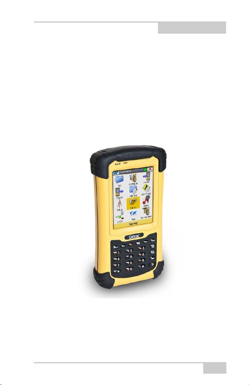
Figure 1-1. Pocket-3D on Controller (Topcon’s FC-236)
NOTE: Pocket-3D now runs on FC25 and FC2500 controllers.
P/N 7010-0628
1-1
Page 24
Installing Pocket-3D
Guide to Installing Pocket-3D
Pocket-3D installs on any hand-held controller that runs the Windows
Pocket PC operating system, including Topcon’s FC236. Pocket-3D
initially loads onto your computer, then uses Microsoft®
ActiveSync® to synchronize with the controller and install Pocket-3D
onto the controller. ActiveSync is available for free from the
Microsoft website (www.microsoft.com) and must be installed on the
computer before installing Pocket-3D.
The Pocket-3D program for your hand-held controller is located on
the 3DMC CD. It will first be loaded onto your computer, then
ActiveSync will install it onto your controller.
1. Connect your computer and hand-held controller.
Because ActiveSync will automatically install Pocket-3D once it
has been loaded onto the computer, this step is can be performed
at any time.
2. Insert the 3DMC software CD into the computer CD drive of the
computer. Navigate to the CD’s files using Explorer and open the
Pocket-3D folder.
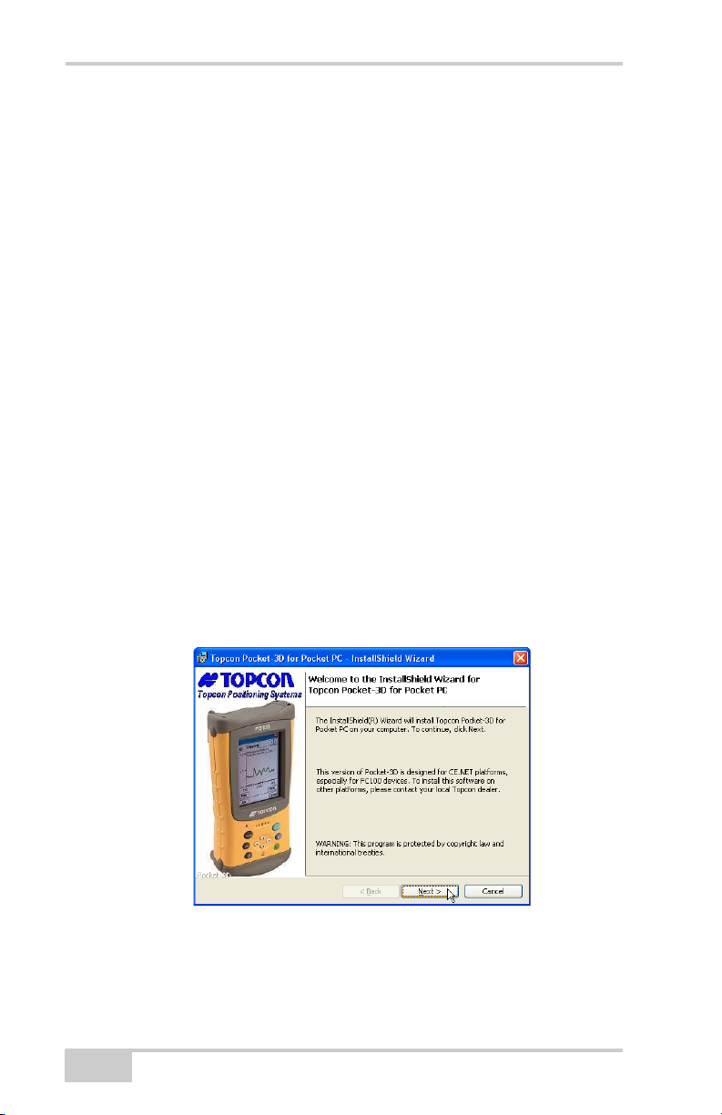
3. Click the Pocket-3D setup icon to run the install program and
click Next on the Welcome screen (
Figure 1-2).
1-2
Figure 1-2. Begin Pocket-3D Installation
Pocket-3D Reference Guide
Page 25
Guide to Installing Pocket-3D
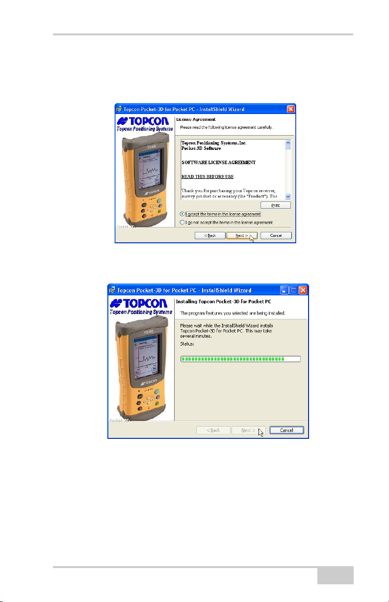
4. Review the License Agreement. If you accept the terms, click the
“I accept...” radio button, then click Next (
Figure 1-3).
Click “I do not accept...” to terminate the installation.
Figure 1-3. Review and Accept License Agreement
5. Click Install to load Pocket-3D on the computer (Figure 1-4).
Figure 1-4. Install Pocket-3D on Computer
6. With the computer and controller connected, ActiveSync will
start up and retrieve the controller’s programs.
If Pocket-3D is already installed, ActiveSync ask to uninstall it
from the controller. When ActiveSync completes the uninstall
process, double-click the Pocket-3D setup icon to have
ActiveSync install the software on the controller.
P/N 7010-0628
1-3
Page 26

Installing Pocket-3D
7. ActiveSync will begin the Pocket-3D install process for the handheld controller (
Figure 1-5).
Figure 1-5. Install Pocket-3D on Controller
8. Click Yes to install Pocket-3D to the default directory on the
controller (
Figure 1-6).
Figure 1-6. Installing into Default Directory
When the controller install completes, ActiveSync displays a
notice to check the controller for any further installation
procedures. However, Pocket-3D has no further installation steps.
Click OK to continue.
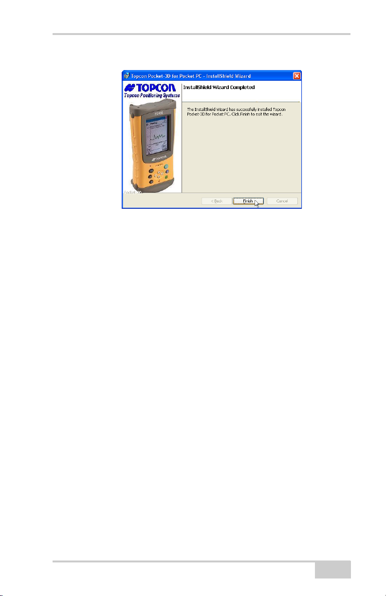
9. Click Finish to exit the install program (Figure 1-7 on page 1-5).
1-4
Pocket-3D Reference Guide
Page 27
Starting Pocket-3D
Figure 1-7. Finish Install and Exit
Starting Pocket-3D
To start Pocket-3D, press theWindows icon and press Pocket3D in
the program list.
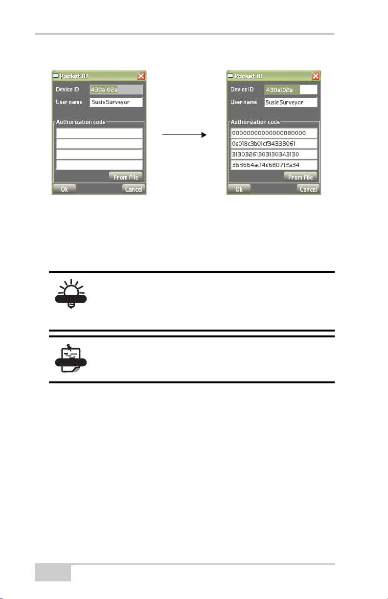
Upon initial startup, Pocket-3D requires authorization codes to
properly run (
mechanism has been changed to allow a larger number of options and
to provide better security. Because the codes are much longer now,
you can import directly from an option file on a USB dongle, etc.
Existing installs of Pocket-3D will automatically be upgraded to the
new protection mechanism. New users will require codes generated
via the new “Keygen2” application.
Figure 1-8 on page 1-6). The password protection
• Device identification
• Company name
•Contact name
• Contact phone number
• Contact email address
• Software Type (Pocket-3D)
• Company address
When you receive the authorization codes, enter them into the
appropriate fields on the Device Identification screen and press Ok
(
Figure 1-8 on page 1-6).
P/N 7010-0628
1-5
Page 28
Installing Pocket-3D
TIP
NOTE
Figure 1-8. Enter Authorization Codes
Once entered, the authorization codes can then be located on the
about Pocket-3D screen for easy access. In v10.0, the authorization
codes no longer change due to new installations. To view updated
installed options, see
“Main Screen” below.
Authorization Codes: More options are now
available to provide better security. Because new
codes are much longer, you can now import them
directly from an option file onto a USB dongle, etc.
Existing installs of Pocket-3D will automatically be
upgraded to the new password protection
mechanism.
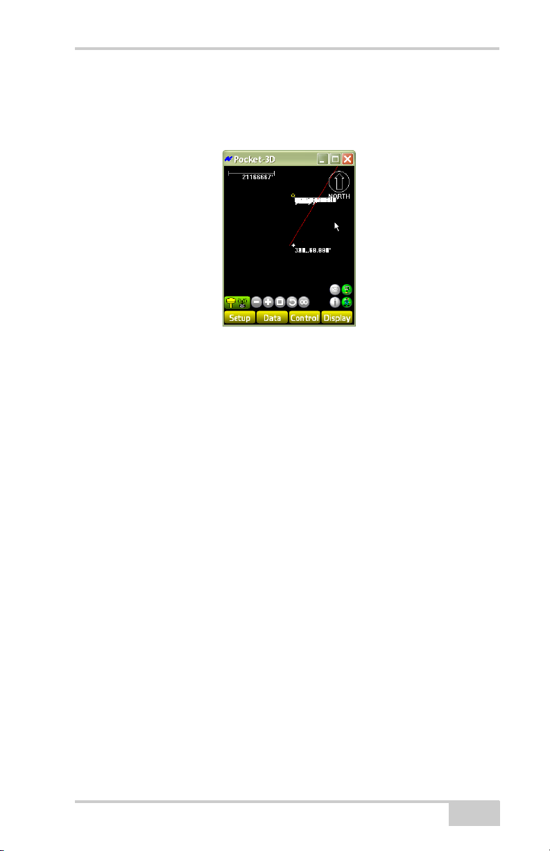
Main Screen
The Pocket-3D main screen (Figure 1-9 on page 1-7) has the
following components:
• Main Window – displays a graphical representation of the design
surface and machine. The display varies according to the selected
file and display options.
• Toolbar – provides icons for frequently used functions. See
“Toolbar” on page 1-12 for more information.
Pocket-3D Reference Guide
1-6
Page 29
Main Screen
• Menu bar – contains pop-up menus for the various functions
available in Pocket-3D. The following chapters describe each
menu in detail.
Figure 1-9. Pocket-3D Main Screen
The pop-up menus on the main screen (Figure 1-12 on page 1-9)
contain frequently accessed functions, and information about selected
data. To display the pop-up menu, rest the controller’s stylus on the
point, station, or polyline for at least one (1) second or alternatively
press the ALT button.
The pop-up (context) menu options depend on the type of file open
and the information selected.
• Clear selection – deselects the selected entities (functions the
same as the Data
Clear selection menu option).
• Hide layer(s) – hides selected layers on the main screen.
• Surface (Figure 1-12 on page 1-9) – sends a message, via SiteLink to the machine operator in the field.
• Alignment (Figure 1-13 on page 1-10):
– Stakeout: stakes out the selected point
– Use as reference line: uses the selected alignment as a
reference line to create/measure new points at a specific
station and offset – same for polyline.
– Send Via Site-Link: sends a message to the operator in the
field.
P/N 7010-0628
1-7
Page 30
Installing Pocket-3D
•Segment (Figure 1-15 on page 1-10) – Add, insert, edit, delete,
create or select entire polyline(s).
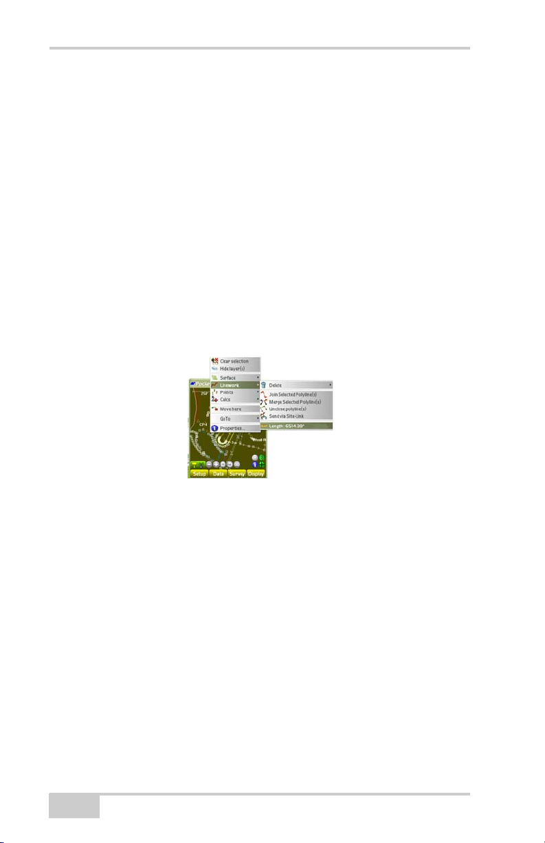
•Linework (Figure 1-10):
– Delete: deletes the selected linework/polyline or the last
segment.
– Join Selected Polyline(s): joins highlighted polylines on the
main screen.
– Merge Selected Polyline(s): merges highlighted polylines on
the main screen.
– Unclose polyline(s): opens previously closed polylines.
– Send via Site-Link: sends a message to the operator in the
field.
– Length: total length of selected polyline
Figure 1-10. Lengths Context Menu Option
• Points – adds, edits, deletes, or stakes-out point(s) (Figure 1-16
on page 1-11)
– Add a point: adds the selected point(s).
– Delete a point: deletes the selected point(s).
– Send via Site-Link: sends a message to the machine operator
in the field.
– Stake-out point: stakes out the selected point(s).
– Use as reference line: uses the selected polyline as a reference
line during a stake-out.
• Calcs – performs common polyline calculations (Figure 1-17 on
page 1-11)
– Create new polyline: creates a new polyline.
1-8
Pocket-3D Reference Guide
Page 31

Main Screen
– Create closed polyline: creates a closed polyline.
– Create tin surface: creates a TIN surface.
– Move object(s): moves the current cursor position to where
the stylus clicked on the main screen (only available in
simulation mode).
– Copy object(s): copies the selected entity with the mouse.
Figure 1-11. Calcs Context Menu Option
Context (Pop-Up) Menu Options
Figure 1-13 through Figure 1-18 shows the context menu options for
Surface, Alignment, Linework, Segment, Point, Calcs, and GoTo
parameters.
P/N 7010-0628
Figure 1-12. Context Menu – Surface Options
1-9
Page 32

Installing Pocket-3D
Figure 1-13. Context Menu – Alignment Options
Figure 1-14. Context Menu – Linework Options
1-10
Figure 1-15. Context Menu – Segment Options
Pocket-3D Reference Guide
Page 33

Figure 1-16. Context Menu – Points Options
Main Screen
P/N 7010-0628
Figure 1-17. Context Menu – Calcs Options
Figure 1-18. Context Menu – GoTo Options
1-11
Page 34

Installing Pocket-3D
Toolbar
The toolbar (Figure 1-19) contains icons for frequently used
functions.
Figure 1-19. Pocket-3D Toolbar – GPS Example
Table 1-1 lists and describes the available icons.
Table 1-1. Pocket-3D Toolbar Icons
Icon Description
GPS, LPS, mmGPS, total station status – displays symbols for the
GPS Status
mmGPS Status
Total Station
Status
Robotic Status
type of control application used on the jobsite, as well as the
connection status (red for unconnected, green for connected, and
orange for low precisions in GPS applications).
• In GPS control applications, press this icon to display GPS
information. See “GPS Status Information” on page 1-17 for
details.
• In mmGPS control applications, press this icon to display GPS
information. See
details.
• In total station applications, press this icon to display total
station information. See
details.
• In robotic applications, press this icon to display robotic
information. See “Robotic Survey Applications” on page 4-63
for details.
Zoom out – decreases the magnification of the design view each
time you tap this button. The zooming pivot is the center of the
screen.
Zoom in – increases the magnification of the design view each
time you tap this button. The zooming pivot is the center of the
screen.
Zoom window – increases the magnification of a design area
when drawing a box around the selected area.
“GPS Status Information” on page 1-17 for
“Total Station Status” on page 1-21 for
1-12
Zoom previous – displays the previous design view.
Pocket-3D Reference Guide
Page 35

Table 1-1. Pocket-3D Toolbar Icons (Continued)
Icon Description
Zoom extents – displays the extent of the design view/area.
Info – displays information for selected points/polylines and a
dialog box to save the information as a text file.
New Message – press to send a new message to the machine
operator in the field.
Site-Link Connection – connects you to Site-Link
Menu Bar
Auto-pan
Selection
window
Selection
polygon
Pan
Click to rotate through the four button options:
• Auto-pan – tracks the user’s current position in the field and
displays the position as a cross symbol in the middle of the
screen. Available only in GPS connection.
• Selection window – selects points/polylines on the screen when
drawing a box around them.
• Selection polygon – selects point/polylines on the screen when
drawing a polygon around them.
• Pan – moves the design view around when pressing down on
the screen and dragging.
Menu Bar
The menu bar provides access to the Pocket-3D configuration, setup,
display, and other jobsite functions (
menus, see the following:
• “Setup Menu” on page 2-1
• “Data Menu” on page 3-1
• “Survey Menu” on page 4-1
Figure 1-20). For details on the
• “Display Menu” on page 5-1
P/N 7010-0628
1-13
Page 36

Installing Pocket-3D
GPS
mmGPS
Total
Station
Figure 1-20. Pocket-3D Menu Bar
Table 1-2 describes the functions available in each menu.
Table 1-2. Pocket-3D Menu Options
Menu Functions
Setup Menus The options available in the Setup menu
depend on the equipment file selected.
• configures equipment and machine setups
• configures radios, antennas, and base
stations in GPS applications
• configures transmitters and receivers in
mmGPS applications
• configures GRT-2000 setup and LS-2000
receivers in LPS applications
• configures total stations and prisms in total
station applications
• sets the units for the job
• Connect to Site-Link
Data Menu The options available in the Data menu
depend on the equipment file and design
surface file selected.
• creates, configures, and sets control point
files
• creates, configures, and sets surface files
• creates, configures and sets linework files
• creates, configures and provides access to
importing or exporting control, files, point
files, and Site-Link files.
• performs various calculations
1-14
Pocket-3D Reference Guide
Page 37

Menu Bar
GPS
mmGPS
Total
Station
Table 1-2. Pocket-3D Menu Options (Continued)
Menu Functions
Survey Menu The options available in the Survey menu
depend on the equipment file selected.
• connects and disconnects the GPS receiver
or total station
• starts and stops tracking the total station in
total station applications
• sets the type of connection for the total
station
• enables and disables the use of a
reflectorless total station in total station
applications
• measures points and polylines in the field
• performs auto-topo operations for
topographic surveys (not available for
some total station instruments/applications)
• performs stake-outs
P/N 7010-0628
1-15
Page 38

Installing Pocket-3D
Table 1-2. Pocket-3D Menu Options (Continued)
Menu Functions
Display Menu The options available in the Display menu
depend on the equipment file selected and the
types of data active.
• zooms in, out, or pans around the main
screen
• selects points and/or polylines individually
or in bunches
• shows the scale bar, the direction of travel,
and/or the point of reference
• orients the screen to a desired direction
• displays, orients, aligns grid lines as
desired
• shows a section view of the design surface
(only available for certain surfaces)
• shows the cut/fill history (available for
mmGPS applications)
• shows the grade indicator when an active
surface displays.
• changes the background color
• selects the language for Pocket-3D on the
next start up of program
• displays the about Pocket-3D dialog box
For pop-up context menu options, see “Main Screen” on page 1-6.
Pocket-3D Technical Information
To view Pocket-3D information, press DisplayAbout Pocket-3D.
The about Pocket-3D dialog box displays the version levels for the
application program, copyright information, registration, and ID
number (
See “Main Screen” on page 1-6 for viewing options.
1-16
Figure 1-21 on page 1-17).
Pocket-3D Reference Guide
Page 39

GPS Status Information
Figure 1-21. About Pocket-3D
GPS Status Information
Once connected to a GPS/mmGPS system, the status button on the
toolbar turns green (GPS) or blue (mmGPS). Press the status button to
view or edit the different application-specific parameters (
on page 1-18).
Figure 1-22
GPS Status
While in GPS control, to view GPS information, change the mask
angle or reset the receiver, press the GPS status button on the toolbar.
The GPS status dialog box displays (
The color of the button and state of the hardware symbol indicates the
status of the system.
• Background color – green means the entire system communicates
with Pocket-3D; red means all or some part of the system is not
communicating with Pocket-3D; orange means low precisions.
• Hardware symbol state – if the symbol is crossed out, the
corresponding sensor/receiver is not available. If the radio link is
between 3 and 10 seconds old, the radio icon will flash (bad or
weak signal); after 10 seconds, it will be crossed out (unavailable
signal).
P/N 7010-0628
Figure 1-22 on page 1-18).
1-17
Page 40

Installing Pocket-3D
GPS Status Icon
mmGPS GPS
Figure 1-22. GPS/mmGPS Status Button and Dialog Box
Monitor GPS Status Information
To monitor the fix status of the GPS+ receiver, press the GPS status
button. The Fix tab displays the following information (
• The initialization status of the GPS+ and mmGPS system
• Total sats tracked – the total (GPS and GLONASS) number of
satellites being tracked
Figure 1-22):
• GPS sats used and GLONASS sats used – the number of GPS and
GLONASS satellites being used
• Horz. RMS and Vert. RMS – an estimation of the positioning
quality computed from a valid satellite status (RMS = Root Mean
Square)
View the Receiver’s Current Position
To view the current position of the GPS+ receiver, press the GPS
status button, then tap the Position tab on the GPS status dialog box.
The Position tab displays the following information (Figure 1-23 on
page 1-19):
• latitude, longitude, and ellipsoid height of the GPS+ antenna
• northing, easting, and elevation of the GPS+ antenna
• the distance from the receiver to the base station
1-18
Pocket-3D Reference Guide
Page 41

GPS Status Information
Monitor Satellites and Enter the Mask
To monitor the current distribution of satellites or enter the mask
angle for satellites, press the GPS status button, then tap the
Satellites tab on the GPS status dialog box.
The Satellites tab displays the following information (Figure 1-23).
• Satellite plot – displays used and unused satellites, and the
current mask angle.
– Blue dots: GPS satellites
– Red-with-cross dots: GLONASS satellites
– Black dots: unused satellites
– Red mask circle: satellites inside will be used for positioning
• Mask – enters and sets the mask angle for the job.
Figure 1-23. Position and Satellites Tabs
View Receiver Information or Reset Receiver
To view the receiver’s ID number and firmware version, press the
GPS status button, then tap the Info tab on the GPS status dialog
box. Use the left/right arrows to navigate to the Info tab.
The Info tab displays the following (Figure 1-24 on page 1-20):
• Identification information, firmware revision, and radio link
information (type, latency, and quality) for the receiver.
• Reset receiver – press to clear all data and reset all settings stored
for the GPS+ receiver.
P/N 7010-0628
1-19
Page 42

Installing Pocket-3D
• Reset RTK – press to reset RTK ambiguities.
View PDOP Values
To view PDOP values for planning purposes, press the GPS status
button, then tap the Planning tab on the GPS status dialog box. Use
the left/right arrows to navigate to the Planning tab.
The Planning tab displays PDOP information at an hourly scale and
covers a 24-hour period (
• Press Next to display PDOP values for the next day.
• Press Previous to display PDOP values for past days.
Figure 1-24).
Figure 1-24. Info and Planning Tabs
Apply GPS Receiver Settings
To apply advanced GPS receiver settings, press the GPS status
button, then tap the Advanced tab (
GPS status dialog box. Use the left/right arrows to navigate to the
Advanced tab.
The Advanced tab contains the following GPS receiver settings.
• Use multipath reduction – leave enabled to reduce multiple
reflections from nearby objects.
• Use GLONASS satellites – leave enabled to include in position
calculations and to display on the satellite plot.
• Base Manufacturer – from the drop-down box, select which GPS
station manufacturer to use, i.e., Sokkia, Ashtech, Javad, Leica,
1-20
Figure 1-25 on page 1-21) on the
Pocket-3D Reference Guide
Page 43

GPS Status Information
NOTE
Select a Base
manufacturer from the
drop-down list
Magellan, Trimble, etc. This helps with correct RTK operation
where GLONASS is used at the base and rover where the base is
not a Topcon base.
Figure 1-25. Advanced Tab
Total Station Status
While in total station control, to view total station information,
change search area or change track sensitivity and speed, press the
Total Station status button on the toolbar (
page 1-22).
Figure 1-26 on
The color of the button and state of the hardware symbol indicates the
status of the system.
• Background color – green means the entire system communicates
with Pocket-3D; red means all or some part of the system is not
communicating with Pocket-3D.
• Hardware symbol state – if the symbol is crossed out, the
corresponding sensor/receiver is not available.
For non-robotic total stations, the prism symbol will
remain crossed out.
The instrument selected during equipment setup determines the tabs
that display.
P/N 7010-0628
1-21
Page 44

Installing Pocket-3D
Total Station
Status Icon
Figure 1-26. Total Station Status Button and Dialog Box
Monitor Prism Position Information
To monitor the position status of the prism, press the Total Station
status button. The Position tab displays the following information
(Figure 1-26):
• whether or not the prism is connected and tracks the total station
• horizontal/vertical angles and slope distance to the prism
• northing, easting, and elevation of the prism
Set Total Station Search Parameters
To set total station search parameters, press the Total Station status
button, then tap the Search tab on the total station status dialog box
(
Figure 1-27 on page 1-23).
Depending on the total station used and the sensor type, enter or
select the following information (
Ok:
• Search wait (secs) – sets the wait time in seconds until the total
station starts to search for the prism (robotic total stations only).
• Pattern – selects the pattern for tracking the prism.
• Search area left and right of prism – when enabled, sets the search
area at the total station for tracking the prism.
1-22
Figure 1-27 on page 1-23) and press
Pocket-3D Reference Guide
Page 45

GPS Status Information
• Above and below prism – enter the angle above and below the
prism in which to search.
Set Total Station Tracking Sensitivity and Speed
To set total station tracking parameters (Figure 1-27), press the Total
Station status button, then tap the Track tab on the total station
status dialog box.
Figure 1-27. Search/Track Tabs for Total Station
P/N 7010-0628
1-23
Page 46

Installing Pocket-3D
Notes:
1-24
Pocket-3D Reference Guide
Page 47

Chapter 2
Setup Menu
Depending on the application (GPS, mmGPS, or total station), the
Setup menu contains different options for configuring system
components.
GPS Applications
In GPS applications, the Setup menu (Figure 2-1) has the following
menu items. Some menu items depend on the type of equipment
configured (machine or rover).
•Equipment
•Radios
• Antenna
• Base Station
• mmGPS transmitters (mmGPS application)
• mmGPS receiver (mmGPS application)
•Units
Figure 2-1. Setup Menu for GPS Applications
P/N 7010-0628
2-1
Page 48

Setup Menu
NOTICE
Equipment
The Equipment menu creates and edits equipment configuration files.
Equipment configuration files contain information specific to the
equipment; such as, machine type, receiver type and location,
dimensions of the cutting edge, offset lengths depending on the
position of the receiver, and radio configuration.
Equipment setup is used for Rover setups, not Base
station setups.
To access available equipment configuration files, tap Setup
Equipment (Figure 2-2).
Figure 2-2. SetupEquipment
From the Equipment configurations dialog box (Figure 2-3 on
page 2-3), equipment configuration files can be created within
Pocket-3D and transferred to the machine Control Box to be used for
machine configuration. (A machine configuration file must be created
before grading.) Refer to the System Five-3D Reference Manual for
more information on the Control Box.
2-2
Pocket-3D Reference Guide
Page 49

GPS Applications
Figure 2-3. Equipment Configurations Dialog Box
Once equipment configuration files are created and stored in the
internal memory, they can be selected and adjusted at the beginning of
the job, depending on the receiver’s setup.
On the Equipment configurations dialog box, press New to display
the Configuration name/type dialog box (
Figure 2-4 on page 2-4)
and create an Equipment Configuration file. Enter the following
information and press Next. Some selections depend on purchased
options for Pocket-3D.
• Configuration name – enter a name for the Equipment
Configuration.
• Machine type – select Range pole, Bulldozer, or Motor grader.
The screens display different settings depending on the machine
type selection.
• Sensor – select the type of sensor used on the machine; either
GPS antenna, GPS Augmented, mmGPS Receiver, Prism, or LS2000 for 3-track curb & gutter.
• Location – select the sensor’s location, either Top of pole for
Range pole, Middle for Bulldozer, or Left/Right for Motor grader.
• Units – select the unit of measure.
Note: These units do not relate to job units.
P/N 7010-0628
2-3
Page 50

Setup Menu
Figure 2-4. Configuration Name/Type
On the antenna information dialog box, enter the following
information using the same units of measure entered in the previous
step and press Next. These settings have a corresponding Image tab to
illustrate the setup.
For range poles, enter the following antenna information
(Figure 2-5):
• Antenna type – select the type of antenna.
• Antenna height – enter the antenna height of the GPS+ antenna
from antenna measurement point to pole tip.
• Measured to – enter where on the GPS+ antenna the antenna
height was measured.
• Connection (Pocket-3D) – select the communication port used
between controller and instrument.
2-4
Figure 2-5. Range Pole Antenna Setup Information
Pocket-3D Reference Guide
Page 51

GPS Applications
On the radio setup dialog box (Figure 2-6), set the following
parameters and press Next:
• Radio type – the type of radio.
• Connected – the port used for radio connection.
• Baud rate – the speed of communication rate between the radio
unit and the GPS+ receiver.
• Format – current GPS+ systems are capable of either CMR or
RTCM corrections.
Figure 2-6. Radio Setup
On the Machine configuration complete dialog box (Figure 2-7),
press Finish to save the configuration file.
Figure 2-7. Machine Configuration Complete Dialog Box
P/N 7010-0628
2-5
Page 52

Setup Menu
Radios
To configure radio settings, tap SetupRadios (Figure 2-8).
Figure 2-8. SetupRadio
On the radio setup dialog box, set the following parameters and press
Ok (
Figure 2-9 on page 2-7):
• Radio type – the type of radio.
• Port – the port used for radio connection.
• Baud rate – the speed of communication rate between the radio
unit and the GPS+ receiver.
• Format – current GPS+ systems are capable of either CMR or
RTCM corrections.
• Configure – changes the radio channel; press to display the
channel configuration dialog box (
Select the desired channel and the corresponding Frequency
displays. Press Set to apply the radio channel parameters.
Figure 2-9 on page 2-7).
2-6
Pocket-3D Reference Guide
Page 53

GPS Applications
Figure 2-9. Radio Setup and Channel Configuration Dialog Boxes
Antenna
To edit/view antenna measurements, tap SetupAntenna
(Figure 2-10).
Figure 2-10. SetupAntenna
On the antenna setup dialog box, set the following parameters and
press Ok (
Figure 2-11 on page 2-8):
• Antenna type – select the type of antenna.
• Antenna height – enter the antenna height of the GPS+ antenna.
• Measured to – enter where on the GPS+ antenna the antenna
height was measured.
• Units – select the unit of measure.
P/N 7010-0628
2-7
Page 54

Setup Menu
NOTE
Figure 2-11. Antenna Setup
Base Station
To set Base Station information, tap SetupBase Station
(Figure 2-12).
If the Base station menu item is unavailable,
disconnect from the GPS receiver (Survey
Disconnect from GPS).
Figure 2-12. SetupBase Station
On the base station configuration dialog box (Figure 2-13 on
page 2-9), set the following parameters and press Next:
• Control point – select the appropriate control point for the base
position from the control point drop-down list.
2-8
Pocket-3D Reference Guide
Page 55

GPS Applications
• Connection (Pocket-3D) – select the connection to the receiver.
Figure 2-13. Base Station Configuration
On the antenna setup dialog box (Figure 2-14), set the following
parameters and press Ok:
• Antenna type – select the type of antenna.
• Antenna height – enter the antenna height of the GPS+ antenna.
• Measured to – enter where on the GPS+ antenna the antenna
height was measured.
• Units – select either meters, feet, inches, or centimeters.
Figure 2-14. Antenna Setup – Base Station
P/N 7010-0628
2-9
Page 56

Setup Menu
On the radio setup dialog box, set the following parameters
Figure 2-15):
(
• Radio type – the type of radio.
• Port – the port used for radio connection.
• Baud rate – the speed of communication rate between the radio
unit and the GPS+ receiver.
• Format – current GPS+ systems are capable of either CMR or
RTCM corrections.
• Configure – changes the radio channel; press to display the
channel configuration dialog box (
Figure 2-15). Select the
desired channel and the corresponding Frequency displays.
• Set – press to apply the radio channel parameters.
• Next – press to display the GPS receiver settings dialog box
(
Figure 2-16 on page 2-11).
Figure 2-15. Radio Setup and Channel Configuration Dialog Boxes
On the GPS receiver settings dialog box (Figure 2-16 on page 2-11)
do the following and press Finish to connect to the GPS receiver.
• Use co-op tracking – if enabled, allows higher efficiency of
multipath reduction. This option is only valid for a base station
receiver (non-moving).
• Use multipath reduction – if enabled, reduces multiple reflections
from nearby objects.
2-10
Pocket-3D Reference Guide
Page 57

GPS Applications
• Use GLONASS satellites – if enabled, these satellites will not be
included in the position calculations and will not display on the
satellite plot if disabled.
Figure 2-16. Select GPS Receiver Settings
Units
To set project units, tap SetupUnits (Figure 2-17).
Figure 2-17. SetupUnits
On the units dialog box (Figure 2-18 on page 2-12), select the desired
units for each item from the drop-down lists. Press Ok to continue;
Pocket-3D saves the entered units.
The units can be changed at any time; Pocket-3D automatically saves
the changes.
• Distances – select either Meters, US Survey feet, International
feet, or Feet + Inches.
P/N 7010-0628
2-11
Page 58

Setup Menu
If using Feet+Inches, all values will show as 1'11''1/2 where 12
inches equal 1 foot and any value smaller than an inch will show
as a fraction of an inch.
• Decimal Places – select either 0, 1, 2, 3, or 4 decimal places.
• Angles – select either DD°MM’SS”, NDD°MM’SS”E, Gons, or
DD.DDDD°.
• Areas – select either Square meters, Square feet, Acres, or
Hectares.
• Volumes – select either Cubic meters or Cubic yards.
• Coords – select either North-East-Elev, East-North-Elev,
X-Y-Z, or X-Y-Z South Azimuth.
• Stations – select either 100.000, 1+00.000, 10+0.000, or
1+000.000.
• Grades – select either Percent (%), Run : Rise, or Rise : Run.
Figure 2-18. Units Parameters
Exit
To exit Pocket-3D, tap the icon in the upper-right corner of the
screen.
2-12
Pocket-3D Reference Guide
Page 59

Equipment Configuration Files
NOTICE
Equipment Configuration Files
Equipment configuration files contain information on the specific
machine, GPS+ receiver, prism, radio, etc., for the job application and
setup. Pocket-3D uses this information to accurately portray jobsite
information on the main screen.
The following sections provide example equipment configurations:
one for a range-pole with a HiPer® Lite receiver, one for a motor
grader machine rover with mmGPS, one for a motor grader with an
LS-2000 receiver, and another one for a prism/total station setup.
An equipment configuration file can be created in one of two ways:
• Import the file created at the System Five-3D Control Box
through the compact flash card using the Copy button. See
“Project” on page 3-2 for details.
• Create the file manually.
Sample Configuration 1: Range-pole with HiPer Lite Receiver
Before initializing or localizing a GPS+ system, there must be an
equipment configuration file defined in Pocket-3D. The following
procedure is an example of a HiPer Lite receiver configuration.
Incorrect measurements or typographical errors will
have a direct affect on grading accuracy.
1. Press SetupEquipment. The Machine files dialog box
displays.
2. On the Machine files dialog box, press New to create (or Edit to
change a selected file) an equipment configuration (
on page 2-14).
3. On the Configuration name dialog box, set the following
equipment parameters, and press Next (
page 2-14):
P/N 7010-0628
Figure 2-19 on
Figure 2-19
2-13
Page 60

Setup Menu
• Configuration name – enter a name for the Equipment
Configuration file on the alphanumeric pop-up keyboard.
• Machine type – select Range pole from the drop-down list.
• Sensor – select GPS Antenna from the drop-down list.
• Mounting location – select Top of pole from the drop-down
list.
• Units – select the type of unit measurement from the
drop-down list.
Figure 2-19. Equipment Configuration Dialog Box
4. Enter the following information on the Dimensions tab using the
same units of measurement entered in the previous step, then
press Next to continue (
Figure 2-20). These settings have a
corresponding Image tab to illustrate the setup.
• Antenna type – select Topcon HiPer Lite.
• Antenna height – enter the antenna’s measured height.
• Measured to – select either Base or Rim.
• Connection (Pocket-3D) – select the appropriate connection.
2-14
Pocket-3D Reference Guide
Page 61

Equipment Configuration Files
Figure 2-20. Antenna Information – Dimensions/Image Tab
5. On the advanced dialog box (Figure 2-21), set the following
radio parameters, and press Next to continue:
• Radio type – for a HiPer Lite, the default is selected;
otherwise, select the radio type for the receiver.
• Connected to – select serial port (usually Port C) from the
drop-down list.
• Baud rate – select 38400 from the drop-down list.
• Format – select CMR from the drop-down list.
6. On the confirmation screen, press Finish to save the
configuration file (
Figure 2-21).
Pressing Cancel will cause the configuration’s information to be
lost.
P/N 7010-0628
Figure 2-21. Radio Setup Dialog Box
2-15
Page 62

Setup Menu
7. On the Equipment configuration dialog box, highlight the new
or edited configuration file, and press Ok to return to the Main
Screen (
GPS Augmented Sensor Type Now you can select a GPS
Figure 2-22).
Figure 2-22. Select Equipment Configuration
(Augmented) sensor type, which allows you to run without RTK
corrections (or without RTK options in your receiver) and to perform
rough grade-checking and stakeout using GPS positions computed
with the help of the WAAS (North America) or EGNOS (Europe)
GPS augmentation system. The expected position accuracies can
range from anywhere between 0.5’ and 4.0’ (0.2m and 1.5m)
depending on satellite availability.
Sample Configuration: GPS Augmented Sensor Type The
following procedure is an example of selecting GPS (Augmented) as
the sensor type for GPS.
1. Follow steps 1 & 2 above, then on the Configuration name
dialog box, select GPS (Augmented) as the sensor type, and press
Next.
2. On the Dimensions tab (Figure 2-23 on page 2-17), select the
antenna type, enter antenna height, measure to either the Base or
the Rim, and select the appropriate connection for Pocket-3D.
The corresponding Image tab illustrates the setup.
2-16
Pocket-3D Reference Guide
Page 63

Equipment Configuration Files
Figure 2-23. Example – GPS (Augmented) Equipment Configuration
3. Press Next to display the confirmation screen dialog box
Figure 2-25).
(
4. Press Finish to return to the Machine files dialog box
(Figure 2-24).
Figure 2-24. Machine Configuration Complete
5. On the Machine files dialog box (Figure 2-25), select the new or
edited configuration file and press Ok.
P/N 7010-0628
2-17
Page 64

Setup Menu
mmGPS Icon
6. On the Machine files dialog box (Figure 2-25), press Ok to apply
the configuration file as the current equipment.
Figure 2-25. Select Equipment Configuration
mmGPS Applications
In mmGPS applications, the Setup menu (Figure 2-26) has the
following additional menu items. Except for mmGPS setup options,
the Setup menu for mmGPS applications is the same as for GPS
applications. Other differences are noted below.
• mmGPS transmitters
• mmGPS receiver
Figure 2-26. Setup Menu for mmGPS Applications
2-18
Pocket-3D Reference Guide
Page 65

mmGPS Applications
Equipment
For further details on the Equipment menu option and setup screens,
“Equipment” on page 2-2. During rover equipment setup for
see
mmGPS applications, an additional screen configures GPS
connections; machine setups for mmGPS remains the same.
mmGPS Transmitters
Transmitter calibration data must first be downloaded into Pocket-3D
using the Transmitters tab (
contains a list of transmitters, up to four transmitters can be set up on
unique channels using the channel tabs (see below). The channel
button on the transmitter determines the channel that the transmitter
broadcasts on.
To set up transmitter information, tap SetupmmGPS transmitters
Figure 2-27).
(
Figure 2-28 on page 2-20). Once this tab
Figure 2-27. SetupmmGPS Transmitters
The Transmitters tab performs the following (Figure 2-28 on
page 2-20):
• To select a Serial Cable – select the communication port used
between the controller and transmitter; either COM or
Bluetooth® comport.
• To add a transmitter – tap Add and enter a transmitter serial
number or other description.
• To delete a transmitter – select a transmitter and tap Delete.
P/N 7010-0628
2-19
Page 66

Setup Menu
• To calibrate the transmitter – see “TX Calibration” on
page 2-21.
• To load transmitter data for the first time – tap Download to
retrieve calibration data from the connected transmitter.
The download is complete when the firmware version displays in
the Firmware column.
Figure 2-28. View Transmitters Loaded into Pocket-3D
The Channel tab displays the following transmitter information
(
Figure 2-29 on page 2-21):
• Channel – the channel the transmitter is using.
• Transmitter – the ID of the transmitter.
• ControlPt. – the control point over which the transmitter is set up.
• Height – the height of the transmitter.
• Edit Channel – see “Edit Channel” on page 2-23.
2-20
Pocket-3D Reference Guide
Page 67

mmGPS Applications
NOTICE
Figure 2-29. Enter Transmitter Channel Information
TX Calibration
The transmitter calibration (adjustment) function fixes errors in
incline in the self-leveling mechanism of the transmitter, applying an
offset to the transmitter. The transmitter must be in calibration mode
for this function and the Rover setup approximately 30 meters (100
feet) away. The height of the sensor must be at an angle less than 1° in
relation to the transmitter.
If the sensor experiences excessive movement
during any stage of the adjustment, an error
message will display. Press Cancel and stabilize the
Rover pole. Then press TX calibration again.
To begin a resection, tap TX Calibration on the Transmitters tab of
the transmitter setup dialog box. If needed, check the setup listed
on-screen (Figure 2-30 on page 2-22) and tap OK.
P/N 7010-0628
2-21
Page 68

Setup Menu
Figure 2-30. Begin TX Calibration Adjustment
On the transmitter adjustment process dialog boxes (Figure 2-31),
follow the instructions on each screen. Press Next to continue.
Figure 2-31. Transmitter Adjustment Process
When the adjustment completes, the Adjustment dialog box displays
the offsets (
Figure 2-32 on page 2-23).
• If both Axis measurements are less than 10'', no adjustment is
needed at the transmitter.
2-22
Pocket-3D Reference Guide
Page 69

mmGPS Applications
TIP
NOTE
• If either or both Axis measurements are more than 10'', disconnect
from the sensor and connect to the transmitter.
• Press Finish to upload the adjustments to the transmitter. When
finished uploading, the transmitter will apply the adjustments and
turn off.
After loading the new self-leveling offset data into
the transmitter, re-calibrate to check the system.
The transmitter may need to be calibrated a couple
of times depending on site conditions.
Figure 2-32. Adjustment Results
This process only applies an offset to the selfleveling mechanism to ensure correct grade. The
control point file is not affected.
Edit Channel
To edit information for the selected transmitter, tap the Edit Channel
button on the Channel tab (
On the edit channel dialog box, edit and select the following
parameters and press Ok to save (
1. Transmitter – select the desired transmitter from the drop-down
list.
2. Control point – select the control point for the transmitter’s
position from the drop-down list.
P/N 7010-0628
Figure 2-33 on page 2-24).
Figure 2-33 on page 2-24).
2-23
Page 70

Setup Menu
3. TX height – enter the height of the transmitter.
4. Measured to – select where on the transmitter (Base or Mark/
Slant) the height was measured.
5. Benchmark check – see “Benchmark Check” below.
6. Resection – see “Resection” on page 2-25.
Figure 2-33. Edit Channel
Benchmark Check
This function determines the height of the mmGPS transmitter over a
known control point (benchmark) or a point of known elevation.
To take a height measurement of the transmitter, tap Benchmark
check on the channel setup dialog box after entering transmitter
information (
2-24
Figure 2-34).
Figure 2-34. Begin Height Check
Pocket-3D Reference Guide
Page 71

mmGPS Applications
On the transmitter height dialog box, select one of the following and
press OK to measure (
Figure 2-35). During the measurement, the
Measuring dialog box displays.
1. If the transmitter is set up over a known control point, tap the first
radio button, then select the control point from the drop-down list.
2. If the transmitter is set up over a point with a known elevation
press the second radio button, then enter the elevation of the
Rover receiver.
When done, the Transmitter height fields display the vertical
difference between the height originally specified for the transmitter
and the calculated height (
Figure 2-35).
3. Press OK to apply the measured height to the transmitter setup.
4. Press Cancel to exit without saving the measurement.
Figure 2-35. Measure Height of Transmitter
Resection
The resection function measures an unknown transmitter location
using the rover and three or more points. In general, the results from a
resection are adequate for horizontal positioning of the transmitter (an
error estimate will also display). Performing a height check and
adjustment will fine-tune the calculated elevation.
When performing a resection, use the following guidelines to ensure
accurate measurements at the Rover points:
P/N 7010-0628
2-25
Page 72

Setup Menu
• take measurements at three or more points around the Base
transmitter in a balanced, symmetrical pattern (not clustered in
one area)
• have the sensor facing towards the transmitter during each
measurement
• angle the sensor between 6° higher or lower than the transmitter’s
beam, not straight on
To begin a resection, press the Resection button on the channel setup
dialog box (
Figure 2-36).
Figure 2-36. Begin Resection
On the resection dialog box, enter the following parameters and press
Measure (
Figure 2-37 on page 2-27). During the measurement, the
Measuring dialog box displays. When done, the Pts. in calculation
field will increment by one.
• Duration (secs) – enter the duration, in seconds, in which to
measure the point.
• H. Precision / V. Precision – enter a horizontal / vertical precision,
in the project’s units, with which to measure the point.
• Measure – After three points have been successfully measured,
horizontal and vertical errors for the measured point will display
Figure 2-37 on page 2-27). Further measurements should
(
improve the positional error.
• Reset – press to clear measurements and start again.
2-26
Pocket-3D Reference Guide
Page 73

mmGPS Applications
The point name will be automatically added to the list of control
points as “TX-[n] (Resected)”, where “n” is the channel number.
Subsequent resections with the same transmitter will overwrite any
previous points.
Figure 2-37. mmGPS Resection Result
mmGPS Receiver
To set mmGPS receiver information, tap SetupmmGPS receiver
(
Figure 2-38).
Figure 2-38. Select mmGPS Receiver Parameters
On the mmGPS setup dialog box, set the following parameters and
press Ok (
Figure 2-39 on page 2-28):
• GPS port – select the port used for communication between
receiver and sensor (typically port D).
P/N 7010-0628
2-27
Page 74

Setup Menu
• Sensitivity – select Auto to automatically control the mmGPS
receiver’s detection level of the transmitter’s signal.
Select a different setting when working at very short or very long
distances, or during inclement weather that can affect laser
detection.
• Channels – select the channel to scan for mmGPS connection.
• Firmware – the firmware version displays after the download of
calibration data from the connected transmitter completes.
• Advanced – select advanced mmGPS options:
– mmGPS aided initialization: select to use the mmGPS signal
to assist in initializing the GPS receiver.
– Calc weighted mmGPS/GPS elevation: select to combine
mmGPS elevations and GPS elevations.
2-28
Figure 2-39. Select mmGPS Receiver Information
Pocket-3D Reference Guide
Page 75

Total Station Applications
Tot al Station
Icon
Total Station Applications
In total station applications, the Setup menu has a Range-pole menu
Figure 2-40).
item (
Figure 2-40. Setup Menu for Total Station Applications
Equipment
For further details on the Equipment menu option and setup screens,
see
“Equipment” on page 2-19.
For the range pole and total station, enter and select the following
information during equipment configuration (
page 2-30), then press Next:
P/N 7010-0628
Figure 2-41 on
• Instrument – select the desired total station (GPT8000).
• 1. Vert. prism height – enter the vertical height of the prism.
• Prism constant – enter the prism constant. This constant is
dependent on the manufacturer of the prism; usually –30 mm for
a single prism and zero for a 360° prism.
• Connection (Pocket-3D) – select the COM1(Serial Port),
COM 2 (Serial 1), or Bluetooth (on equipped total stations).
2-29
Page 76

Setup Menu
NOTE
Figure 2-41. Setup/Image Tabs for Total Station
On the Advanced dialog box (for prism sensors only), select how you
want to connect the total station (
Figure 2-42 on page 2-31), then
press Next.
• Cable in STD mode – select to connect the total station via serial
cable or Bluetooth if the total station is in STD (standard)
measurement mode.
• Cable in Ext. Link mode – select to connect the total station via
serial cable or Bluetooth.
• RC4 Modem (Ext.Link) – select to connect the total station via
RC4 modem if the total station is in external link mode.
• Remote Control – select to connect the total station via serial
cable or Bluetooth if the total station is in external link mode.
• Baud rate – select either 600, 1200, 2400, 4800, or 9600
• Data Bits – select either 7 or 8
• Stop Bits – select either 1 or 2
• Parity – select either Odd or Even
For a conventional total station, the GTS 200 for
example, you can only connect via Cable in
Standard Mode.
2-30
Pocket-3D Reference Guide
Page 77

Total Station Applications
NOTE
Figure 2-42. Select Total Station Connection Type
The Advanced dialog box is only available when a
Prism sensor is selected.
A confirmation box displays to save the machine configuration file.
Press Finish (
Figure 2-43).
Figure 2-43. Save the Configuration
Range-pole
To set up the range pole, tap SetupRange-pole (Figure 2-44 on
page 2-32).
On the range pole setup dialog box (Figure 2-44 on page 2-32), select
or enter the following parameters and press Ok.
P/N 7010-0628
2-31
Page 78

Setup Menu
• Units – select the unit of measure.
NOTE: These units do not relate to job units.
• Vert. dist. from prism center to pole tip – enter the measured
distances for the prism and the offset.
– Height of prism: enter the vertical height of the prism.
– Prism offset: enter the prism offset.
Figure 2-44. Range Pole Parameters
Sample Configuration 4: Prism and Total Station
Before beginning to track a prism, there must be an equipment
configuration file defined in Pocket-3D. The following procedure is
an example of a prism configuration for a GPT-8000 series total
station.
1. Press SetupEquipment to create or select an equipment
configuration file. The following steps describe creating a file.
2. On the Machine files dialog box, press New to create (or Edit to
change) a total station configuration (
3. On the Configuration name dialog box, set the following
equipment parameters, and press Next (
page 2-33).
• Configuration name – enter a name for the configuration file.
• Machine type – select Range pole from the drop-down list.
• Sensor – select prism from the drop-down list.
2-32
Figure 2-45 on page 2-33).
Figure 2-45 on
Pocket-3D Reference Guide
Page 79

Total Station Applications
• Mounting location – select “Top of pole” from the drop-down
list.
• Units – select the type of unit measurement from the
drop-down list.
Figure 2-45. Equipment Configuration File for Total Station
4. Enter the sensor information using the same units of measure
entered in the previous step, then press Next to continue
Figure 2-46 on page 2-34). These settings have a corresponding
(
Image tab to illustrate the setup.
• Instrument – select the desired total station from the
drop-down list.
• Vert. prism height – enter the vertical height of the prism.
• Prism constant – enter the prism constant. This constant is
dependent on the manufacturer of the prism; usually -30 mm
for a single prism and zero for a 360° prism.
• Connection (Pocket-3D) – select the communication port
used between the controller and instrument; COM1 (Serial
port) or Bluetooth® on equipped total stations.
P/N 7010-0628
2-33
Page 80

Setup Menu
Figure 2-46. Sensor Information Dialog Box
5. On the Advanced dialog box, select the connection type, Baud
rate, Data Bits, Stop Bits, and Parity used for communication
with the total station and press Next to continue (
Figure 2-47).
NOTE: The RC4 Modem is now supported in order to
communicate with robotic total stations.
6. Press Finish to save the configuration file (Figure 2-47).
NOTE: Pressing Cancel will cause the configuration’s
information to be lost.
2-34
Figure 2-47. Select Advanced Parameters
Pocket-3D Reference Guide
Page 81

Robotic Applications
7. On the Machine files dialog box (Figure 2-48), select the new or
edited configuration file, and press Ok to return to the main
screen.
Figure 2-48. Select Equipment Configuration
Robotic Applications
The Setup menu for robotic applications is about the same as for
range pole applications (
below.
Figure 2-49). The differences are noted
P/N 7010-0628
Figure 2-49. Setup Menu for Total Station Applications
2-35
Page 82

Setup Menu
Equipment
To communicate to the controller using the radio, do the following:
1. Click SetupEquipmentNew.
The Configuration dialog box displays (Figure 2-50 on
page 2-37).
2. For the range pole and robot application, enter a name for the
robotic application, select Range pole as machine type, and a
Prism as the sensor type.
3. Select GTS900MC as the communication port used between the
controller and the instrument (
GTS900 [Figure 2-51 on page 2-37]) and connect via Radio
Modem (COM3)((Figure 2-50 on page 2-37) or RC3/BT COM6
(Figure 2-51 on page 2-37).
4. Press Next.
5. The Setup/Image dialog box displays (Figure 2-50 on page 2-37).
6. Press Next again (the Advanced dialog box displays) to connect
via the Radio Modem (
(Figure 2-51 on page 2-37).
Figure 2-50 on page 2-37) or the RC3
Figure 2-50 on page 2-37) (or
2-36
Pocket-3D Reference Guide
Page 83

Equipment
Figure 2-50. Using Radios (COM3) as Communication
The type of communication selected determines the equipment setup
configuration.
Figure 2-51. Using RC3 (BT COM6) as the Communication Device
P/N 7010-0628
2-37
Page 84

Setup Menu
Station Setup
To set the occupy and backsight stations of the instrument, tap
Station Setup (Figure 2-52).
Setup
Figure 2-52. SetupStation Setup
On the setup method dialog box (Figure 2-53 on page 2-39), set the
parameters for the four station setup methods: Known station & BS
pt, Known station & azimuth, New station by Resection, and
Unknown pts, then press Next.
Known station & BS pts: the most common method. Select a station
point and a backsight point from the list of control points for the job
site.
1. On the Setup method dialog box (Figure 2-53 on page 2-39), set
the following parameters:
• Instrument height – enter the measured height of the
instrument.
• Units – enter the units used to measure the height of the
instrument, then press Next.
The backsight setup dialog box (Figure 2-53 on page 2-39)
displays.
2. On the backsight setup dialog box, select or enter the following
parameters, then press Next:
• Filter List – select either Control points or Point from the
drop-down list.
• Layer – select a layer from the drop-down list.
2-38
Pocket-3D Reference Guide
Page 85

Station Setup
Backsight Setup Dialog Box
Setup Method Dialog
• Station – select the control point over which the instrument is
set (only if ‘Point’ is selected in the FIlter List field above).
• Backsight – select the control point used as the backsight.
• Backsight has prism – check mark this box if the backsight
has a prism.
– Target height: enter the height of the backsight prism.
– Prism constant: enter the prism constant for the backsight
prism.
Figure 2-53. Known Station & BS Points Setup Method
Known station & azimuth select a station point from the list of
control points and enter an azimuth value for the orientation.
1. On the Setup method dialog box (Figure 2-55 on page 2-40),
enter instrument height and unit of measurement as described on
page 2-38.
The backsight setup dialog box displays.
2. On the backsight setup dialog box (Figure 2-55 on page 2-40),
select or enter the following parameters:
• Filter List – select either Control points or Point from the
drop-down list.
• Layer – select a layer from the drop-down list, if ‘Point’ was
selected from the Filter List.
• Station – select the control point the instrument is over.
P/N 7010-0628
2-39
Page 86

Setup Menu
Sight
Backsight
Setup method dialog box Backsight Setup Dialog Box
• Backsight azimuth – enter the desired azimuth for the
backsight.
3. Press Ok to continue (Figure 2-54).
Figure 2-54. Sight Backsight Dialog Box
4. Press Next to display the sight backsight dialog box
(Figure 2-54).
Figure 2-55. Known Station and Azimuth Setup Method
New station by resection add a control point to the resection and
take a measurement to each point.
1. On the Setup method dialog box (Figure 2-56 on page 2-41),
enter instrument height and unit of measurement as described
above, (
The control points dialog box displays (Figure 2-56 on
page 2-41).
2-40
page 2-38) then press Next.
Pocket-3D Reference Guide
Page 87

2. On the control points dialog box, do the following:
NOTE
Control Points dialog
Setup Method dialog box
• Add – press to add point/control points to the resection. The
Backsight results dialog box (
Figure 2-57 on page 2-42)
displays.
• Edit – press to edit a highlighted point/control point, then
press Ok to return to the control points dialog box.
Figure 2-56. New Station by Resection Setup Method
Station Setup
On the Backsight results dialog box (Figure 2-57 on page 2-42),
select or enter the following parameters:
• Filter List – select either Control points or Point from the drop-
• Layer – select a layer file from the drop-down list, if Points was
• Name – select the control point to be used in the resection from
P/N 7010-0628
• Delete – press to delete a highlighted point/control point on
the control points dialog box, then press Ok.
Press Yes to confirm or No to cancel.
You can use any number of points, but at least 3
points should be used for an accurate resection.
Once computed, add the new, resected point to the
control point file.
down list.
selected from the Filter List.
the drop-down list.
2-41
Page 88

Setup Menu
Control Points dialog
Backsight Results dialog
• Usage – select either H. Angle only, H.&V. Angles, H.,V. Angles &
SD., or Disabled to specify how the control point will be used.
• HT – enter the height of the control point’s prism.
• PC – enter the prism constant of the control point’s prism.
• H.Angle – enter the horizontal angle difference.
• V.Angle – enter the vertical angle difference.
• S.Dist – enter the slope distance difference.
• Observe – press to measure the control point.
Figure 2-57. Backsight Results
Unknown point automatically creates this point in the database as
point 1.
1. On the Setup method dialog box (Figure 2-56 on page 2-41),
enter instrument height and unit of measurement as described
above, (
page 2-38) then press Next.
The Station coordinates dialog box displays (Figure 2-58 on
page 2-43).
2. The Station coordinates dialog box (Figure 2-58 on page 2-43)
verifies the North(ing), East(ing), and Elev(ation) for the new
control point.
2-42
Pocket-3D Reference Guide
Page 89

Station Setup
Figure 2-58. Station Coordinates Dialog Box
3. Press Finish to continue (Figure 2-58). The sight backsight
dialog box displays.
The sight backsight dialog box (Figure 2-59), sights the
backsight.
4. Press Ok to continue.
P/N 7010-0628
Figure 2-59. Sight Backsight
2-43
Page 90

SiteLink® 3D for
Pocket-3D
SiteLink-3D is an advanced communications system for Machine
Control Grade Suite of products. It connects every aspect of the
jobsite – the machine operator in the field, the surveyors, the grade
checkers, and office personnel. The Site-Link Manager Software
manages the communications network and can only be used by
system administrators. Using Sitelink Manager software, the
administrator initially sets up each Pocket-3D user with an operator
name and specific activities and delays. Generally, Site-Link Manager
allows the system administrator to:
• Save all data sent by machines from the jobsite to a database
• Send data to all people on the jobsite, i.e., machine operator
survey crews, office personnel, etc., no need to use USB sticks.
• Communicate will all people on the jobsite via a messaging
system – no need to stop the machine before talking to the driver
in the field.
• Update design files and other data on the machine at the jobsite
with the latest points, lines, etc.
• View all machines and other survey crews and their position on
Pocket-3D to see what task they are currently working on –
increases safety and productivity
• Troubleshoot (remotely) from the office to insure that the
surveyor has the right files or if there are problems with the radio;
you can also view the controller and remotely talk to the survey
about any problems that arise.
• Receive real time support through the Topcon support group
• Receive GPS corrections over Sitelink
• Maintain historical data inside the database for safety and
security
Page 91

SiteLink® 3D for Pocket-3D
• Check productivity of the crew – who was working on what, how
productive was the crew – to determine if more workers are
needed
The Site-Link Network Connection
The Site-Link Manager Software manages the initial setup of the
computer system that manages the Site-Link 3D communications
network.
1. Press SetupSite-LinkNetwork Connection (Figure 2-60).
Figure 2-60. Network Connection
2. On the Site-Link Connection dialog box (Figure 2-61 on
page 2-46), set the following parameters:
• Server name/port – Select a port ID address from the dropdown menu or press the
• SiteID – display-only field that shows the name of the site.
– : press to display alphanumeric keyboard to enter
server address.
• Timeout (secs) – enter a time-out value.
• MachineID – enter a machine description.
• Status – shows if status is connected/disconnected to server.
• Ok – press to accept selections and return to the Main Screen.
• Cancel – press to quit without saving changes and return to
the Main Screen.
P/N 7010-0628
2-45
Page 92

Setup Menu
NOTE
Figure 2-61. The Site-Link Connection
Once you return to the main screen, the Site-link
icon
turns Green when connected. If Site-link is
not connected, the Sitelink icon turns Red.
Connecting to SiteLink-3D
To connect to Site-Link, upon Pocket-3D startup, enter the Site-Link
3D password.
Contact your Topcon dealer for the password.
Figure 2-62. Start-up Screen
2-46
Pocket-3D Reference Guide
Page 93

Connecting to SiteLink-3D
NOTICE
NOTE
To download a project file, see “Exporting a Project File Via SiteLink” on page 2-51 for more information.
You must have an active project enabled to connect
to Site-Link 3D.
Selecting the Current Operator
Press SetupSite-LinkOperator (see “Add, Edit, or Remove
Registered Machine Operators” on page 2-47) to select an operator to
add, edit, and remove registered machine operators. This same list of
operators will be seen each time the machine operator using 3DMC
connects to Site-Link.
Figure 2-63. Add, Edit, or Remove Registered Machine Operators
It is important that all new operators get added to
Site-Link Manager as soon as possible so that data
reports will not indicate invalid or null operator
associations.
Managing Activities/Delays
Press SetupSite-LinkActivity/Delay (administrator only) to
add, edit, or remove registered machine activities and delays
(
“Monitor Machine Activities/Delays” on page 2-48). Only then can
the Pocket-3D machine operator select an appropriate activity or
delay from the same list given to him/her on the machine. From this
P/N 7010-0628
2-47
Page 94

Setup Menu
Activity
Machine Delays
list you can also see what specific task a machine is currently
performing, which becomes helpful in creating database reports later
on.
Figure 2-64. Monitor Machine Activities/Delays
Sending, Viewing, and Deleting Messages
With Site-Link, you can send and receive messages from the machine
operator at the jobsite. Do the following to send a message:
1. Press SetupSite-LinkNew message to send a message to
the machine operator at the jobsite or click on the new message
icon
on the main screen to view the unread message; just click
Reply to respond to the message.
NOTE: When the new message icon is Yellow, there is an
unread message
2. On the messages To:screen (Figure 2-65 on page 2-49), use either
the pop-up keyboard and the mouse or the computer keyboard, to
enter a new message.
3. Press Ok to return to the Main Screen.
2-48
Pocket-3D Reference Guide
Page 95

Connecting to SiteLink-3D
To: Messages
Screen
Figure 2-65. Enter a Message for the Machine Operator
To view a new message, do the following:
1. Press SetupSite-LinkView message(s).
2. On the view messages dialog box (Figure 2-66), press Reply to
answer the message shown on the screen.
The screen shows the day and time the message was sent.
3. Press Ok to send the message.
4. Press Cancel to return to the Main Screen.
P/N 7010-0628
Figure 2-66. Send and Receive Messages
2-49
Page 96

Setup Menu
NOTE
When a new message arrives in Pocket-3D, you will
hear a “Ding-Dong” sound on the main screen.
To delete a message, do the following:
1. Press SetupSite-LinkDelete message(s) (Figure 2-67).
2. Press Ok to delete all messages and return to the Main Screen
Figure 2-67).
(
Figure 2-67. Delete Messages
Send Any File to the Jobsite
If there is a file the machine operator needs, it is possible to send a file
to the operator without delay.
1. Press SetupSite-LinkSend any file (Figure 2-68 on
page 2-51).
2. On the Open dialog box, highlight a file to select it and press
Open.
3. On the Send dialog box, highlight a file to send in to To field.
In the To field, you can select the machine, office computer, or
any other survey crew to send the file(s) to.
4. Press control-Shift to send to multiple people. You can even send
the file to people off-line if the Show offline clients box is
2-50
Pocket-3D Reference Guide
Page 97

Connecting to SiteLink-3D
marked (Figure 2-70 on page 2-52). Any type of file can be sent.
5. Press Ok to send the file to the machine operator on the jobsite.
Figure 2-68. Send Any File
Exporting a Project File Via Site-Link
1. Press DataProjectImport/ExportVia Site-Link
(Figure 2-69).
Figure 2-69. Select Project File Via Site-Link
The Pocket-3D confirmation dialog box displays (Figure 2-70 on
page 2-52).
2. If you press Yes on the Pocket-3D confirmation dialog box, do
the following:
•On the import/export To: dialog box, highlight to select the
desired project file for import/export (
Figure 2-70 on
page 2-52).
P/N 7010-0628
2-51
Page 98

Setup Menu
2
4a
2a
4
2
2b
2c
5
3
• Check mark the Show offline clients box to display both
online and offline clients and enter a description if you prefer
(optional), then press Next.
3. On the project selection dialog box, check mark the Set as
Current active project box only if you want to overwrite the other
client’s current project(
Figure 2-70).
If this the box is unchecked, the file goes to the clients “in box”
where he can later retrieve the file by pressing Copy
From
Inbox.
4. On the project selection dialog box, check mark the Overwrite
project w/same name box if the project name is the same as one
that already exist (
Figure 2-70), then press Next.
5. Press Finish to save and return to the Main Screen.
Figure 2-70. Import-Export Control Data
6. If you press No on the Pocket-3D confirmation dialog box, do
the following to select individual items:
2-52
Pocket-3D Reference Guide
Page 99

Connecting to SiteLink-3D
Select Linework(s)
Select Points
Select Control Data
• On the Pocket-3D confirmation dialog box, press No.
•On the Surface(s) dialog box, highlight a file to select it, then
press Next (
Figure 2-72 on page 2-53).
Figure 2-71.
7. On the Linework(s), Point(s), and Control Data dialog boxes,
check and enable the desired selection after pressing Next
Figure 2-72).
(
Figure 2-72. Linework, Point, and Control Data Dialog Boxes
8. After pressing Next on the Control data dialog box, the import
data dialog box displays (
P/N 7010-0628
Figure 2-73 on page 2-54).
2-53
Page 100

Setup Menu
9. Press Next to display the Send dialog box (Figure 2-73).
10. On the Send dialog box (Figure 2-73), press Finish to save
changes and return to the Main Screen.
Figure 2-73. Importing/Exporting Control Data
Importing/Exporting Control Points Via Site-Link
To add, edit, delete, or import/export a control point via Site-Link, do
the following:
1. Press DataControlImport/ExportVia Site-Link
(Figure 2-74).
Figure 2-74. Import/Export Control Points
2. On the Control data dialog box (Figure 2-75 on page 2-55),
check mark the box to import the entire localization, control
points, and mmGPS transmitter data into the project file.
2-54
Pocket-3D Reference Guide
 Loading...