

Page 1
INSTRUCTION MANUAL
PixelChart
PC-50S
Page 2

Page 3
INTRODUCTION
This symbol is applicable for EU member countries only.
To avoid potential damage to the environment and possibly human health, this
instrument should be disposed of (i) for EU member countries - in accordance with
WEEE (Directive on Waste Electrical and Electronic Equipment), or (ii) for all other
countries, in accordance with local disposal and recycling laws.
Thank you for purchasing the TOPCON PixelChart PC-50S.
This instrument is the visual acuity chart which is used by connecting to CV-5000.
(Unless this instrument is connected to CV-5000, it cannot operate as a visual acuity chart.)
This instrument has the following features:
• The active chart in which the targets are changed and moved is installed.
You can realize the patient's eye condition by the target's move.
• The animation playback function is installed. You can check a variety of visual condition as
watching the displayed image.
• You can set the test distance by intervals of 25cm in the range of 2.5m ~ 6m.
• Maintenance-free design because the display unit is made of liquid crystal.
This instruction manual outlines the PixelChart PC-50S, including the basic operation, trouble
shooting, maintenance and cleaning of this product.
To ensure the best use of the instrument (safely and efficiently), please carefully read "DISPLAY FOR SAFE USE" and "SAFETY CAUTIONS" and then use the instrument correctly
prior to operating the PC-50S.
Keep the instruction manual on hand for future reference.
This instrument should be used by connecting to the CV system.
There are three methods to operate PC-50S through CV-5000.
• Operate PC-50S with 1Dial Controller KB-50S.
• Connect mouse to monitor and operate PC-50S with mouse.
• Connect a personal computer to CV-5000 and operate PC-50S with it.
This manual is made according to the operation with KB-50S. In the case of "Mouse operation" and "Personal computer operation", understand this manual by changing the words to
the specified ones as shown in the following table.
Controller unit/CV software
screen of 1Dial Controller
Monitor unit/CV software
screen of 1Dial Controller
KB operation Mouse
operation
Notation Switch Button Button
Action Press Click Click
Display of
setting menu
Display of
test list
Action Touch Click Click
[Shift]+
[Menu]
[Shift]+[Prog] [Examination
[Settings]
button
list]
Personal computer
operation
[Settings]
button
[Examination list]
1
Page 4

CAUTIONS FOR USE
Basic caution
When installing the instrument on a wall, use the wall-mounting metal fixture, which is one of the components,
and install it on the strong wall that can support its weight. (Do not install it on the plaster-board wall.)
[The instrument may fall off to cause a trouble or injure someone.]
Fix the wall-mounting metal fixture, which is one of the components, on the wall as taking care for its direction.
[The instrument may fall off to cause a trouble or injure someone.]
Set the test distance of the instrument correctly.
[The reliability of the measurement result may be lowered.]
Be careful not to damage the liquid crystal display or stain it with fingerprint, dust or others.
[The reliability of the measurement result may be lowered.]
Disposal
Dispose of the instrument according to local disposal and recycling laws.
ENVIRONMENTAL CONDITIONS FOR USE
Temperature : 10°C - 40°C
Humidity : 30% - 90% (non-condensing)
Air pressure : 700hPa - 1060hPa
STORING METHOD, USAGE PERIOD AND OTHERS
1. Storage (without wrapping (without package))
* Temperature: 10°C - 40°C
Humidity: 10% - 95% (without dew condensation)
Air pressure: 700hPa - 1060hPa
* THIS INSTRUMENT DOES NOT MEET THE TEMPERATURE REQUIREMENTS OF ISO 15004-
1 FOR STORAGE. DO NOT STORE THIS INSTRUMENT IN CONDITIONS WHERE THE TEMPERATURE MAY RISE ABOVE 40°C OR FALL BELOW 10°C.
2. Storage (with wrapping (with package))
Temperature: -20°C - 50°C
Humidity: 10% - 95%
3. Transportation (with wrapping (with package))
Temperature: -40°C - 70°C
Humidity: 10% - 95%
4. When storing the instrument, ensure that the following conditions are met:
(1) The instrument should not be splashed with water.
(2) Store the instrument away from the environment where air pressure, temperature, humidity,
ventilation, sunlight, dust, salty/sulfurous air, etc. could cause damage.
(3) Do not store or transport the instrument on a slope or uneven surface or in an area where it is
subject to vibrations or instability.
(4) Do not store the instrument where chemicals are stored or gas is generated.
5. Usage period
8 years from delivery providing regular maintenance is performed (according to the self-certification
[Topcon data])
CHECKPOINTS FOR MAINTENANCE
Maintenance by user
1. Regularly maintain and check the instrument and its parts.
2. Make sure that the test distance of the instrument is set correctly.
3. Make sure that the instrument is installed on the wall or on the Floorstand, which is an accessory, securely.
4. When using the instrument after a prolonged period of inactivity, confirm normal and safe operation beforehand.
5. If the liquid crystal display is stained, clean it.
6. When this instrument is not in use, apply the dust cover to it.
For details, refer to "PREPARATION BEFORE USE" and "MAINTENANCE."
2
Page 5
DISPLAY FOR SAFE USE
To encourage safe and proper use and to prevent danger to the operator and others or potential damage
to property, important cautionary messages are placed on the instrument body and inserted in the instruction manual.
We suggest that everyone using the instrument understands the meaning of the following displays, icons
and text before reading the "SAFETY CAUTIONS" and observe all listed instructions.
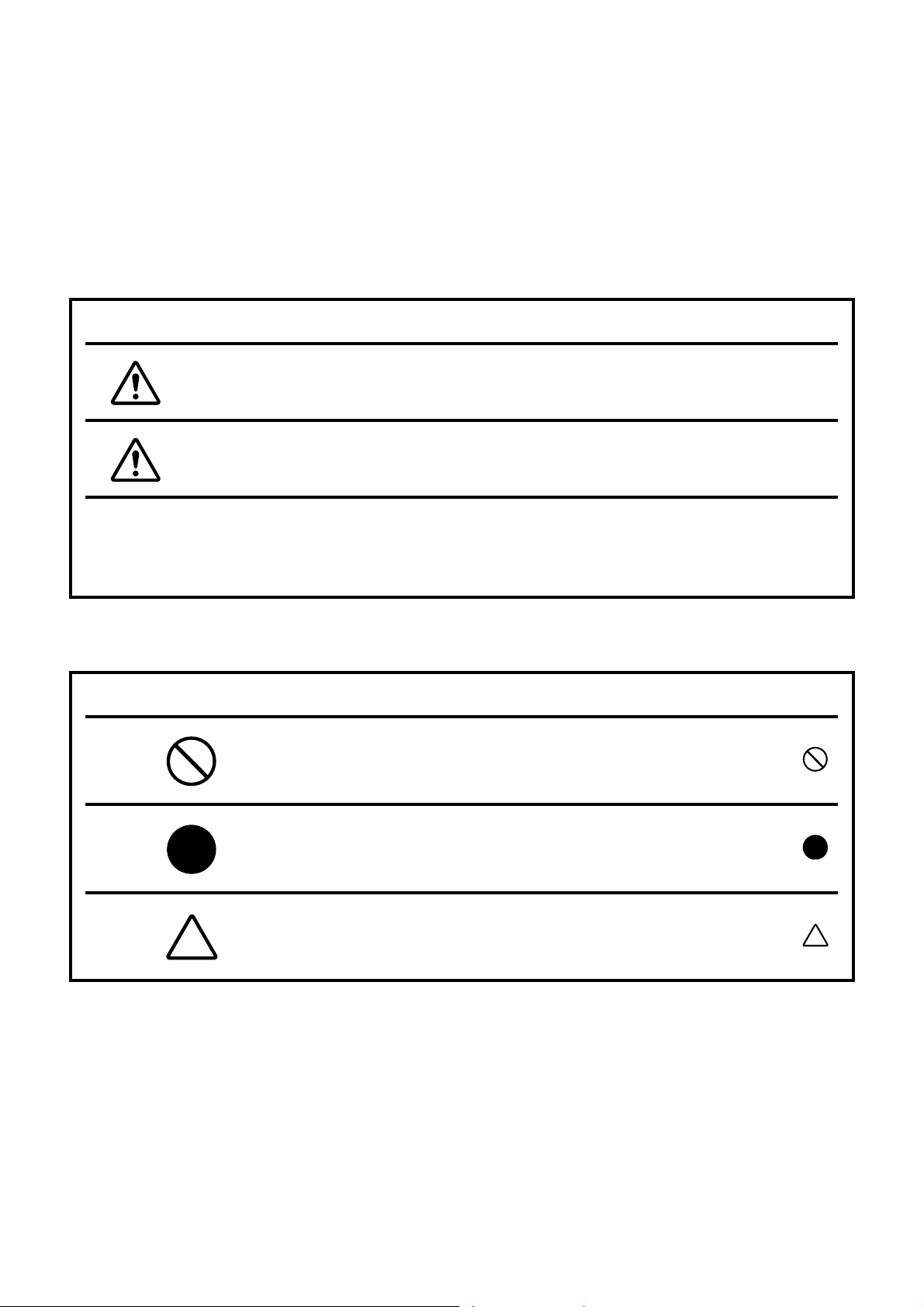
DISPLAYS
Display Meaning
Incorrect handling by ignoring this display may lead to a risk of
WARNING
CAUTION
Injury refers to cuts, bruises, burns, electric shock, etc. which do not require hospitaliza-
tion or extended medical treatment.
Physical damage refers to extensive damage to the building, nearby equipment and/or
surrounding furniture.
death or serious injury.
Incorrect handling by ignoring this display may lead to personal injury or physical damage.
ICONS
Icon Meaning
Prohibition:
Specific content is expressed with words or a picture near the
icon.
Mandatory Action:
Specific content is expressed with words or a picture near the
icon.
Caution:
Specific content is expressed with words or a picture near the
icon.
3
Page 6
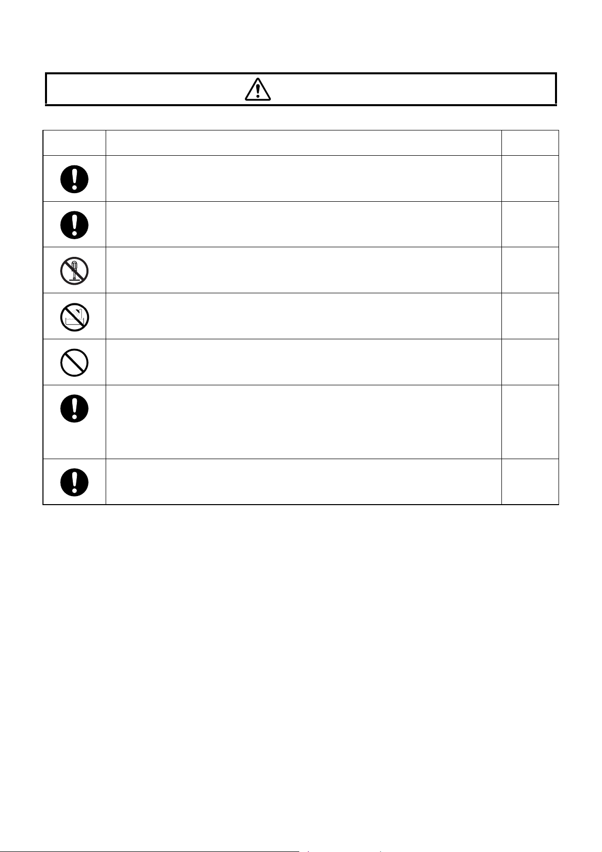
SAFETY CAUTIONS
WARNING
Icons Prevention Item Page
To avoid injury, do not touch the terminal while the AC adapter is in use. ----
To avoid fire and electric shock in case of leakage, be sure to use a grounded
outlet. Do not connect to outlets that are not grounded.
To avoid electric shock, do not remove the cover. Contact your local authorized dealer or Topcon office (listed in back cover) to repair the instrument.
To avoid fire and electric shock, install the instrument in a place free of water
and other liquids.
To avoid fire and electric shock, do not insert metal objects into any clearance,
etc.
To avoid fire in the event of an instrument malfunction, immediately turn off the
power switch and remove the power plug from the outlet if you see smoke
coming from the instrument or if you detect other problems. Don't install the
instrument where it is difficult to disconnect the power plug from the outlet.
Ask your dealer for repairs.
To avoid fire or electric shock, turn off the power of the instrument and remove
the power plug from the outlet before inspecting or cleaning the instrument.
17
38
----
----
----
40
4
Page 7
CAUTION
Icons Prevention Item Page
To avoid electric shock, do not handle the plugs with wet fingers. 17
To avoid electric shock, do not touch the external connection terminal and the
patient at the same time.
Tighten the screws securely not to be loosened. If the screw is loosened, the
instrument may fall off to cause a trouble or injure someone.
When installing the instrument on a wall, use the wall-mounting metal fixture,
which is one of the components, and install it on the strong wall that can support its weight. (Do not install it on the plaster-board wall.) The instrument may
fall off to cause a trouble or injure someone.
Fix the wall-mounting metal fixture on the wall as taking care for its direction.
The instrument may fall off to cause a trouble or injure someone. If the instrument is installed slantwise, the reliability of the measurement result may be
lowered.
When installing the instrument, keep the space of 5cm or more above and
under the instrument not to block the vents on its top and bottom surfaces.
The instrument may be heated to burn someone or cause a trouble.
When using the wall-mounting metal fixture, pass the clearance rings, which
are the accessories, through the wall-mounting screws to be installed on the
instrument body. In this condition, fix the screws securely. If not, the instrument may fall off to cause a trouble or injure someone.
12
14
15
15
14
41
Do not put substances above the vent on the top surface of the instrument.
The instrument may be heated to burn someone or cause a trouble.
----
5
Page 8

CAUTION
To prevent the reliability of the measurement result from being lowered, set the
test distance of the instrument correctly.
Be careful not to damage the liquid crystal display or stain it with fingerprint,
dust or others. The reliability of the measurement result may be lowered.
This instrument has been tested (with 100V/230V) and found to comply with
IEC60601-1-2 Ed.3.0: 2007.
This instrument radiates radio frequency energy within standard and may
affect other devices in the vicinity.
If you have discovered that turning on/off the instrument affects other devices,
we recommend you change its position, keep a proper distance from other
devices, or plug it into a different outlet. Please consult the dealer from whom
you purchased the instrument if you have any additional questions.
40
14
----
6
Page 9

MAINTAINABLE RANGE
USER MAINTENANCE
To ensure the safety and performance of this instrument, all maintenance work, unless specified in this
manual, shall be conducted by trained service engineers.
The following maintenance task may be done by the user.
For details, see "MAINTENANCE" in this manual.
CLEANING THE LIQUID CRYSTAL DISPLAY
The liquid crystal display of the instrument can be cleaned by the user. For details, refer to "Cleaning
the liquid crystal display" on page 40 in this manual.
CHECKING THE MOUNTING UNITS FOR LOOSENESS
The user can check if the mounting units of this instrument are loosened. For details, refer to "Checking the mounting screws for looseness" on page 41 in this manual.
ESCAPE CLAUSE
• TOPCON shall not take any responsibility for damage due to fire, earthquakes, actions by third persons and other accidents, or damage due to negligence and misuse by the user and any use under
unusual conditions.
• TOPCON shall not take any responsibility for damage derived from inability to properly use this
instrument, such as loss of business profit and suspension of business.
• TOPCON shall not take any responsibility for damage caused from using this instrument in a manner other than that described in this instruction manual.
• Diagnoses made shall be the responsibility of pertaining doctors and TOPCON shall not take any
responsibility for the results of such diagnoses.
7
Page 10
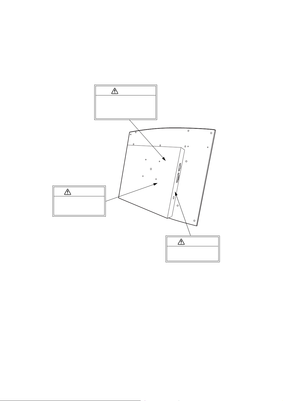
WARNING DISPLAYS AND POSITIONS
CAUTION
Tighten the screws securely not
to be loosened. If the screw is
loosened, the instrument may fall
off to cause a trouble or injure
someone.
WARNING
To avoid injury caused by
electric shock, do not open
the cover.
Ask your dealer for service.
WARNING
Do not the touch terminal
while using the AC adapter.
Doing this may cause injury.
To ensure safety, the machine provides warning displays.
Use the instrument correctly by observing the display instructions. If any of the following display labels
are missing, contact your TOPCON dealer or your local Topcon office listed on the back cover of this manual.
8
Page 11

CONTENTS
INTRODUCTION .............................................................................................................................. 1
CAUTIONS FOR USE ................................................................................................................. 2
ENVIRONMENTAL CONDITIONS FOR USE ............................................................................. 2
STORING METHOD, USAGE PERIOD AND OTHERS .............................................................. 2
CHECKPOINTS FOR MAINTENANCE ....................................................................................... 2
DISPLAY FOR SAFE USE ............................................................................................................... 3
SAFETY CAUTIONS ........................................................................................................................ 4
MAINTAINABLE RANGE ................................................................................................................. 7
USER MAINTENANCE ...............................................................................................................7
CLEANING THE LIQUID CRYSTAL DISPLAY ........................................................................... 7
CHECKING THE MOUNTING UNITS FOR LOOSENESS ......................................................... 7
ESCAPE CLAUSE ........................................................................................................................... 7
WARNING DISPLAYS AND POSITIONS ........................................................................................ 8
BEFORE USE ...............................................................................................................................11
STANDARD COMPONENTS ......................................................................................................... 11
OPTIONAL ACCESSORIES .......................................................................................................... 11
NOMENCLATURE .................................................................................................................... 12
PREPARATION BEFORE USE ....................................................................................... 14
INSTALLING THE INSTRUMENT .................................................................................................. 14
CONNECTING TO COMPU-VISION CV-5000 .............................................................................. 16
CONNECTING THE POWER CORD ............................................................................................. 17
PILOT LAMP STATUS ................................................................................................................... 18
REGISTERING THE VISUAL ACUITY CHART ............................................................................. 18
INDICATION OF CHART ...................................................................................................... 20
SETTING .......................................................................................................................................... 34
SETTING THE LIQUID CRYSTAL DISPLAY ................................................................................. 34
SETTING THE CHART .................................................................................................................. 35
TROUBLE SHOOTING .......................................................................................................... 38
TROUBLE SHOOTING GUIDE ...................................................................................................... 38
MAINTENANCE .......................................................................................................................... 40
DAILY CHECKUPS ........................................................................................................................ 40
USER MAINTENANCE ITEMS ...................................................................................................... 42
SPECIFICATIONS & PERFORMANCE ..................................................................... 43
OPERATION PRINCIPLE .............................................................................................................. 43
PURPOSE OF USE/EFFICACY OR EFFECT ............................................................................... 43
SPECIFICATIONS BY ITEMS ........................................................................................................43
PATIENT’S ENVIRONMENT ......................................................................................................... 43
9
Page 12

OTHER SPECIFICATIONS ............................................................................................................ 44
DIMENSIONS AND WEIGHT ......................................................................................................... 44
ELECTRIC RATING ....................................................................................................................... 44
ELECTROMAGNETIC COMPATIBILITY ....................................................................................... 45
Requirements for the EXTERNAL DEVICE ................................................................................... 48
SYSTEM CLASSIFICATION ..........................................................................................................49
CONVERSION OF TEST DISTANCE (REFERENCE) .................................................................. 49
SHAPE OF PLUG .......................................................................................................................... 50
SYMBOL ........................................................................................................................................ 50
AC ADAPTER ................................................................................................................................ 50
10
Page 13

BEFORE USE
INSTRUCTION MANUAL
PixelChart
PC-50
STANDARD COMPONENTS
The table below shows the standard components. Make sure that you have all of the components.
The numerical value in ( ) shows the quantity. If one of the standard components is not included in the
package, contact your dealer or TOPCON office (listed in the back cover).
Instruction manual (1) Power cord (1) AC adapter (1)
Dust cover (1) Wall-mounting metal fixture (1) Wooden screw for fixing the
wall-mounting metal fixture (4)
Wall-mounting screw (4) Clearance ring (5)
(One of them is a spare.)
Spacer for mounting the
wireless unit (2)
Use this part only when using the wall-mounting metal fixture to install the PixelChart.
Use this part only when installing the wireless unit.
Screw for the wireless unit
(commercial product) (2)
OPTIONAL ACCESSORIES
The service engineer will connect the optional accessories. When you purchase the optional
accessories, contact the service engineer.
• Image cable : This should be connected to CV-5000.
• Floor stand : This stand should be placed on the floor.
11
BEFORE USE
Page 14
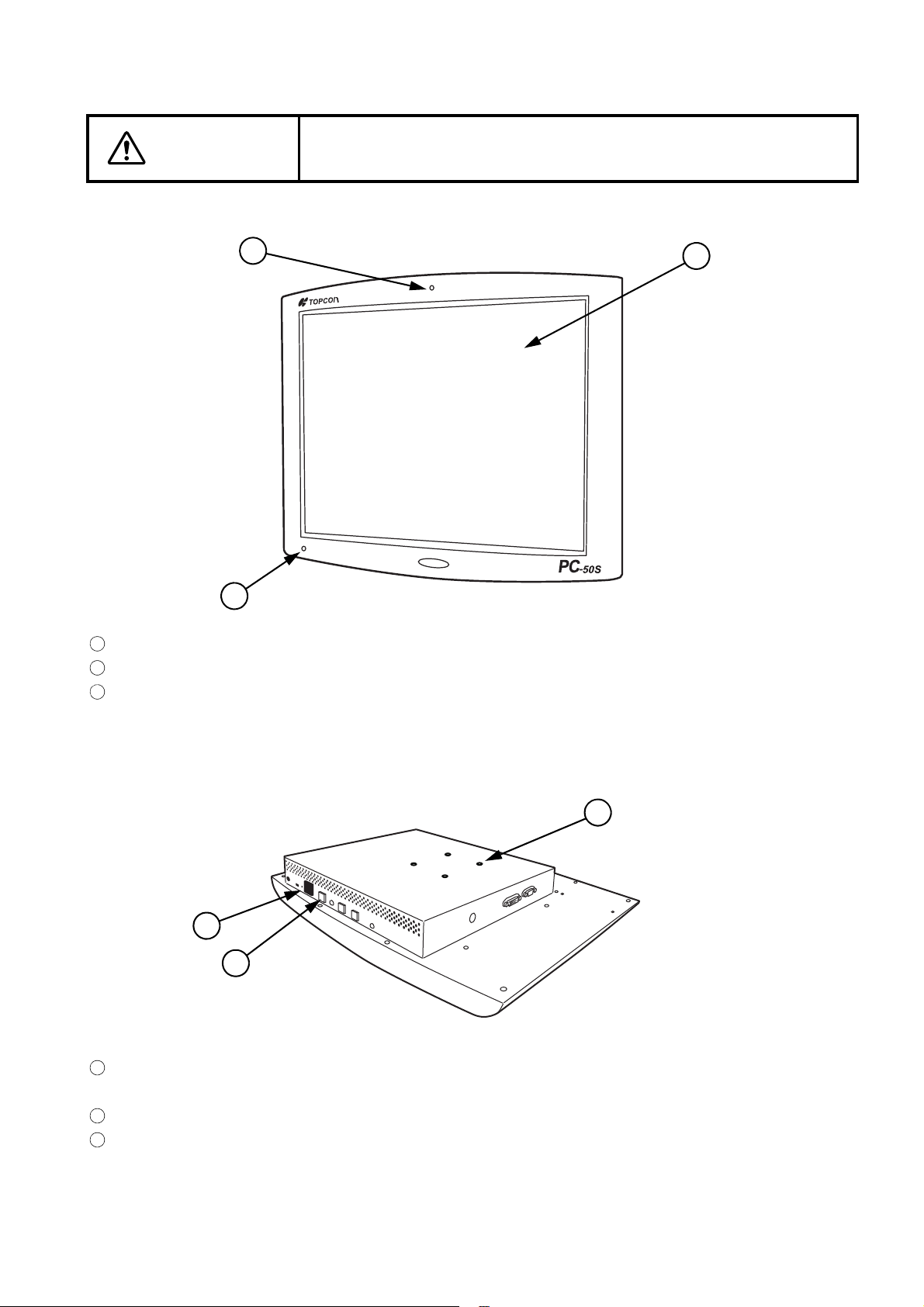
NOMENCLATURE
2
3
1
123
4
5
6
456
To avoid electric shock, do not touch the external connection terminal
CAUTION
Front surface
and the patient at the same time.
Liquid crystal display: Presents the chart.
Fixation target lamp: Used for the Maddox test and others.
Pilot lamp: Displays the power supply condition of the instrument.
Lower rear surface
Mounting hole (4 places): These screw holes are used to install the instrument on the wall-
Function switch (3 pcs.): Used to set the instrument.
Power switch: Turn on this switch. The pilot lamp is lit green and the instrument can
mounting metal fixture or the Floorstand.
receive the image signal.
12
NOMENCLATURE
Page 15
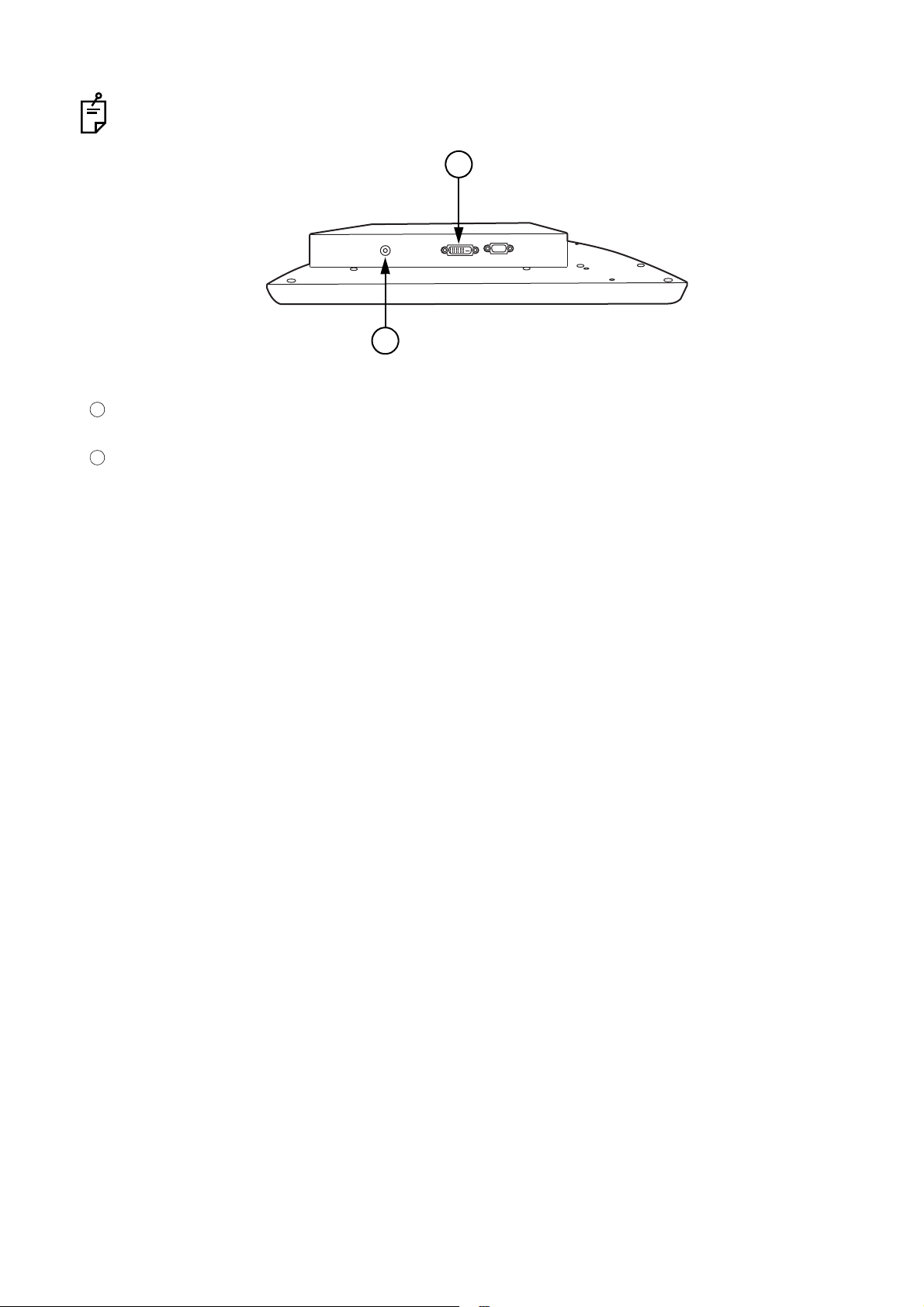
Side surface
8
7
7
8
Cover is attached to the analog VGA connector. Don't use this connector.
DVI connector: Used to connect with the external devices (CV-5000 only). Ask the
AC adapter jack: Used to connect the power plug.
serviceman to connect the instrument with the external devices.
13
NOMENCLATURE
Page 16
PREPARATION BEFORE USE
INSTALLING THE INSTRUMENT
When installing the instrument, keep the space of 5cm or more above
and under the instrument not to block the vents on its top and bottom
CAUTION
CAUTION
CAUTION
surfaces. The instrument may be heated to burn someone or cause a
trouble.
Be careful not to damage the liquid crystal display or stain it with fingerprint, dust or others. The reliability of the measurement result may be
lowered.
Tighten the screws securely not to be loosened. If the screw is loosened, the instrument may fall off to cause a trouble or injure someone.
NOTICE
Install the instrument on the wall, using the wall-mounting metal fixture.
In addition to the wall-mounting method, you can use the Floorstand, which is an optional accessory, or the stand for the commercial liquid crystal display to mount the instrument.
The interval between the screw holes in this instrument is 75mm × 75mm.
On the liquid crystal display, there is sometimes noticeably unevenness on the background due to
the disturbing light. To prevent the sunlight or disturbing light from contacting with the liquid crystal
display directly, change the installing place or direction of the instrument.
Use the accessory screws to fix the instrument.
14
PREPARATION BEFORE USE
Page 17
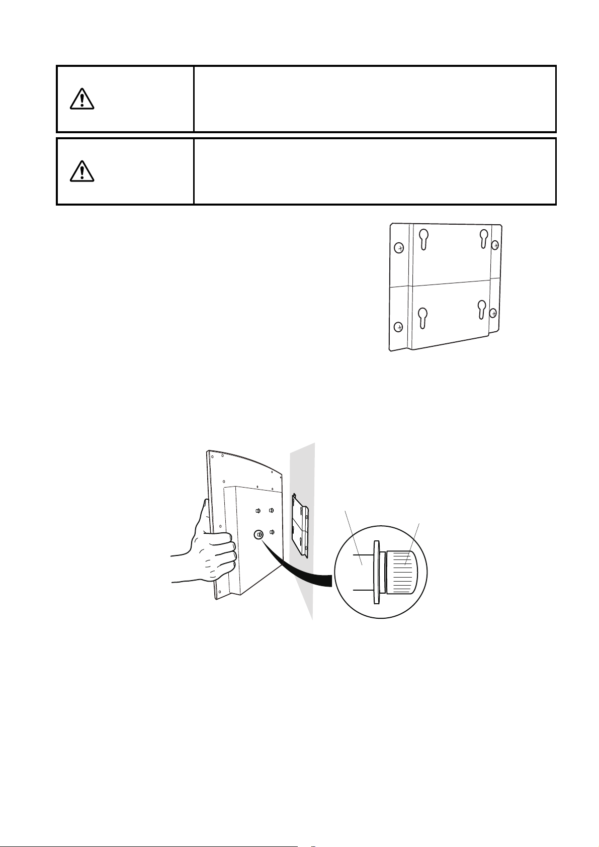
When installing the instrument on a wall, use the wall-mounting metal
Clearance ring
Wall-mounting screw
fixture, which is one of the components, and install it on the strong wall
CAUTION
CAUTION
that can support its weight. (Do not install it on the plaster-board wall.)
The instrument may fall off to cause a trouble or injure someone.
Fix the wall-mounting metal fixture on the wall as taking care for its
direction. The instrument may fall off to cause a trouble or injure someone. If the instrument is installed slantwise, the reliability of the measurement result may be lowered.
1 Decide the position to install the wall-mounting
metal fixture on the wall. The standard for position-
ing is that the horizontal line stamped on the wall-
mounting metal fixture should be aligned with the
center height of the liquid crystal display. Fix the
metal fixture on the wall securely with the four
wooden screws, which are the accessories.
2 Fix the four wall-mounting screws on which the clearance rings are set into the screw holes on
the instrument's rear surface securely.
3 Hang the instrument on the wall-mounting metal fixture.
15
PREPARATION BEFORE USE
Page 18

CONNECTING TO COMPU-VISION CV-5000
CV system
PC-50S
This instrument is connected to the CV system and is used as a visual acuity chart.
As shown below, connect the image cable to the DVI connector of this instrument.
This instrument can be connected to only the following devices: CV POWER SUPPLY UNIT WITH
BUILT-IN PERSONAL COMPUTER or the personal computer connected to CV POWER SUPPLY
UNIT WITH EXTERNAL PERSONAL COMPUTER. This instrument cannot be connected to the
CV power supply unit and the personal computer connected with the CV power supply unit.
CV-5000
Refer to the CV-5000 instruction manual for the connection method on the CV system.
16
PREPARATION BEFORE USE
Page 19

CONNECTING THE POWER CORD
To avoid fire and electric shock in case of leakage, be sure to use a
WARNING
grounded outlet. Do not connect to outlets that are not grounded.
CAUTION
To avoid electric shock, do not handle the plugs with wet fingers.
1 Set the AC adapter to the side surface of the instrument.
2 Connect the power cord to the AC adapter.
3 Insert the power cord plug into the 3-plug AC outlet with proper grounding.
PREPARATION BEFORE USE
17
Page 20

PILOT LAMP STATUS
The pilot lamp color in each instrument status is shown below.
(1) OFF: AC adapter; Not connected.
Power switch; ON/OFF
(2) Lit in orange: AC adapter; Connected.
Power switch; OFF
(3) Lit in green: AC adapter; Connected.
Power switch; ON
REGISTERING THE VISUAL ACUITY CHART
Operate this instrument through CV system. This chapter will explain the setting procedure of the
visual acuity chart that is necessary to use this instrument.
1 Turn on this instrument and the power supply unit.
* When operating through personal computer:
Turn on this instrument, the power supply unit and the personal computer to start the CV
software.
2 As pressing the [Shift] switch, press the [Menu] switch.
The "Settings" menu is displayed.
3 Touch the [Chart settings] button.
The menu to select the chart that should be connected is displayed.
18
PREPARATION BEFORE USE
Page 21

4 Set "PC-50S" for "Device" of "For far vision" and "F" for "Type" (This manual will explain the
example in which "F" is used as "Type".). Then, select "PC-50S" for "Chart monitor selection".
5 Touch the [Chart software config.] button and then the [Chart settings] button. The "CHART
SETTINGS" screen appears. Set [Examination distance] according to the real test distance.
Touch the [OK] button and then the [Exit] button. The "Chart settings" screen appears again.
Refer to "SETTING THE CHART" on P.35 for the details about setting of chart.
6 Touch the [OK] button and then the [Exit] button to save the setting and finish the procedure.
19
PREPARATION BEFORE USE
Page 22

INDICATION OF CHART
PC-50S has the functions peculiar to the image indication type. This instruction manual will explain the
charts peculiar to PC-50S. For general indication of chart, refer to the Compu-Vision CV-5000 instruction
manual.
This manual will explain the indication of chart when "F" is used as "Type".
The Compu-Vision CV-5000 instruction manual describes the tests when the charts ACP-8 is
used.
When the test distance is set to 4.25m or more, the visual acuity 0.02 cannot be indicated. When
the test distance is set to 2.75m or less, the visual acuity 2.0 cannot be indicated.
When the instrument is set to indicate the visual acuity, it is indicated at the right side of the chart.
When some large chart is indicated, the visual acuity is indicated at the upper or lower right.
Sometimes, even if the system is set to indicate the visual acuity in big size, it is forcedly indicated
in small size.
Indicating targets at random
While the visual acuity chart is indicated, touch the [Random] button among the function buttons. The
targets arrangement can be changed at random.
The example of use is shown below.
1 Indicate the tumbling E chart [0.2-0.4].
2 Touch the [Random] button.
The targets on the line of "Visual acuity 0.2" are changed at random.
3 Touch the [Random] button again.
The targets on the line of "Visual acuity 0.2" are changed at random.
4 Press the [] switch.
The targets on the line of "Visual acuity 0.3" are changed at random and are indicated.
5 Press the [] switch.
The targets on the line of "Visual acuity 0.2" are changed at random and are indicated.
The one character chart's targets can be indicated at random.
When one character is masked on the chart, you cannot use the random indication function.
20
INDICATION OF CHART
Page 23

Reversing the black-and-white condition of chart
While the visual acuity chart is indicated, press the [Shift] switch. The [Reverse] button is displayed as
the function button. Touch the [Reverse] button. The black-and-white condition of the chart being displayed is reversed.
* When operating through mouse/personal computer:
Click the button on the CV software screen, and the black-and-white condition of the chart
can be reversed.
The example of use is shown below.
1 Indicate the tumbling E chart [0.2-0.4].
2 Touch the [Reverse] button.
The black-and-white condition of the chart is reversed.
3 Touch the [Reverse] button again.
The black-and-white condition of the chart is reversed to be the normal condition.
While the black-and-white condition of the chart is reversed, it is possible to apply a mask, to indicate the targets at random and to indicate other visual acuity charts in the reverse condition.
Stereoscopic vision
Set the red and green lenses, which are the auxiliary lenses, to the right and left eyes respectively and
then perform the test. Measure the degree of stereoscopic vision. Two lines are seen in fusion to form
a single line image and floated against the central circle.
The binocular parallax is about 13'.
21
INDICATION OF CHART
Page 24

Astigmatism chart (application of the active chart)
12
1
2
3
4
5
6
7
8
9
10
11
12
1
2
3
4
5
6
7
8
9
10
11
180
12
1
2
3
4
5
6
7
8
9
10
11
45
For the astigmatism chart, two or more types of radiation can be selected by setting. Moreover, there
is the function to indicate the cylinder axis more accurately.
1 Select the astigmatism chart from the chart page and indicate it on the liquid crystal display.
You can perform the normal astigmatism test in this condition.
2 Touch the [Rotate] button among the function buttons.
The radial lines except the "12 o'clock" and "6 o'clock" lines are changed to light-color.
3 Turn the dial according to "Dial Navigation", and you can rotate the deep color line by 5°. Turn
the dial until the deep color line is seen most clearly.
Turn the dial in the "+" direction of "Dial Navigation". The cylinder axis rotates counterclockwise.
Turn the dial in the "-" direction of "Dial Navigation". The cylinder axis rotates clockwise.
* When operating through mouse/personal computer:
Operate the mouse according to "Mouse Navigation", and you can rotate the deep color
line by 5°. Operate the mouse until the deep color line is seen most clearly.
Click the right mouse button on the mouse navigation. The cylinder axis rotates clockwise.
Click the left mouse button on the mouse navigation. The cylinder axis rotates counterclockwise.
22
INDICATION OF CHART
Page 25

Special function (Single rate character contrast)
It is possible to indicate the whole chart in the single contrast rate.
The example of use is shown below.
1 Indicate the tumbling E chart [0.2-0.4].
2 Touch the [Contrast] button among the function buttons.
The contrast selection menu is displayed.
3 Select "Contrast" from the contrast selection menu. When the contrast has been changed and
you press the [] or [] switch, the chart can be changed in the changed contrast condition.
The contrast can be changed by the following stages, "100%, 50%, 25%, 12.5%, 10%, 5.0%,
2.5%".
When the contrast has been changed, touch the other visual acuity chart (excluding "screening")
button. The chart can be changed in the changed contrast condition.
Touch the [Exit] button on the contrast selection menu, and contrast is canceled.
23
INDICATION OF CHART
Page 26

Special function (Plural rate character contrast)
Different contrast rate is given to each column of the chart and, in this condition, the chart can be indicated.
The example of use is shown below.
1 Indicate the tumbling E chart [0.2-0.4].
2 Touch the [Contrast] button among the function buttons.
The contrast selection menu is displayed.
3 Touch the [Plural rate] button on the contrast selection menu.
The tumbling E chart [0.2-0.4] in which the columns are different in contrast by stages, "25%",
"12.5%", "10%", "5%" and "2.5%" from the leftmost one is displayed.
4 Press the [ ] switch.
The tumbling E chart [0.5-0.7] having the plural rate contrast is indicated.
Select the chart having 3 lines and 5 columns from the chart page. The chart can be changed in
the contrast condition. Touch the [Exit] button on the contrast selection menu, and contrast is canceled.
While the character chart or the chart having 2 lines and 3 columns is being indicated, it is not possible to select the [Plural rate] button on the contrast selection menu.
24
INDICATION OF CHART
Page 27

Picture
Icon on the chart page
Near-point image (KB-50S) Far-point image (PC-50S)
Icon on the chart page
1 Select the image from the chart page.
2 The near-point image is appeared on KB-50S and the far-point image, on the PC-50S display.
When operating through mouse/personal computer, the near-point image does not appear.
3 Touch the [Display] button among the function buttons, and the near-point image (KB-50S) is
canceled.
Select any other chart, and the selected chart is appeared on the instrument.
Slideshow
1 Select "Slideshow" from the chart page.
The image slideshow is played.
Select any other chart.
"Slideshow" is canceled and the selected chart is indicated on the instrument.
25
INDICATION OF CHART
Page 28

Movie
Icon on the chart page
ROOT
PC-50S_UC
Still
Selective
KB50S
Slide
Movie
This folder is used to save each JPEG image that is displayed on PC-50S.
This folder is used to save the BMP image related to each still image, which
is displayed on PC-50S, and this BMP image is displayed on KB-50S.
This folder is used to save the JPEG image, which is displayed on PC-50S
when executing "Slideshow".
1 Select "Movie" from the chart page.
The movie is played.
Select any other chart.
The movie is finished and the chart is appeared.
Custom chart
Still images and movies prepared by the user appear on the instrument. For slideshow, still images
can be registered up to "20" and, for displaying each of them, registered up to "20". In addition, still
images can be registered up to "20" for displaying each of them on KB-50S at the same time. The
movie file can be registered up to "2".
1 Make the folders under USB memory in the following configuration and save the file in these fold-
ers.
2 Insert the USB memory to the CV system and start the system.
3 Touch the [Chart settings] button on the "Settings" menu to display the "Chart settings" screen.
26
INDICATION OF CHART
Page 29

4 Touch the [Chart page registration] button on the "Chart settings" screen to display the "Chart
Custom still image Custom movie Custom slideshow
page registration" screen. Register the icons for the custom still image, custom movie and cus-
tom slideshow.
5 Return to the test screen. Touch the icons of the custom still image, custom movie and custom
slideshow to play back the still image and movie.
* File format and filename
• Still image to be saved in "Selective" and "Slide"
Format is JPEG and size is optional. The still image is displayed on the whole screen of PC-50S
during playback. The filename must be 01.jpeg - 20.jpeg.
• Still image to be saved in "KB50S"
Format is BMP and size is fixed at 800×600. The still image cannot be displayed in any other
size. The filename must be 01.bmp - 20.bmp. When the file saved in "Selective" is accessed
through KB-50S, the BMP file with the same number is displayed on KB-50S as a near-point
image.
When operating through mouse/personal computer, the near-point image does not appear.
INDICATION OF CHART
27
Page 30

• Movie to be saved in "Movie"
The movie conditions are as follows: It is a WMV video encoded by CODEC Windows Media
Video 7 - 9. The maximum movie size is 1280×1024. The bit rate is 10Mbps and frame rate is
30fps. (These conditions are applied when PC-50S is connected through the DVI cable.) The filename must be 01.wmv and 02.wmv.
When operating through personal computer, sometimes the playback of movie is not smooth due
to the specification of the used personal computer.
28
INDICATION OF CHART
Page 31

BALANCE TEST (POLARIZATION)
Refer to "BALANCE TEST (POLARIZATION)" in the CV-5000 instruction manual for details of the test
method.
Set the red and green lenses on the instrument, which are the auxiliary lenses, to the right and left eyes
respectively and then perform the test.
Item Description
The red lens is set to the right eye and the green
lens, to the left eye.
Auxiliary lens
(The left illustrations are the status as seen from
the operator side as shown on the CV-5000 software screen.)
BALANCE TEST (POLARIZATION: 2-COLOR)
Refer to "BALANCE TEST (POLARIZATION: 2-COLOR)" in the CV-5000 instruction manual for details
of the test method.
In this instrument, the base-up prism of "6 prism" as the auxiliary lens is set to the right eye.
The balance test (polarization: 2-color) cannot be performed for some types.
Item Description
The base-up prism of "6 prism" is set to the right
eye.
Auxiliary lens
Check the adjusted status of the right eye.
The image the patient sees is separated in the up-and-down direction by the prism inserted to the right
eye. The patient sees the R/G on the upper column with the right eye and the R/G on the lower column
with the left eye. Have the patient compare the columns and answer which column is seen better.
(The left illustrations are the status as seen from
the operator side as shown on the CV-5000 software screen.)
29
INDICATION OF CHART
Page 32

COINCIDENCE TEST (V)
Refer to "COINCIDENCE TEST (V)" in the CV-5000 instruction manual for details of the test method.
Set the red and green lenses on this instrument, which are the auxiliary lenses, to the right and left
eyes respectively and then perform the test.
Item Description
The red lens is set to the right eye and the green
lens, to the left eye.
Auxiliary lens
(The left illustrations are the status as seen from
the operator side as shown on the CV-5000 software screen.)
1 Check the vertical aniseikonia.
When the patient sees the test chart through the R/G auxiliary lenses, the center fixation target is
seen by both eyes. In addition, the left half is seen by the left eye and the right half, by the right
eye as shown below.
2 Touch the [Scale Simulate] button among the function buttons on the screen to perform the active
chart test.
3 Operate the dial to adjust the chart.
Let the patient answer whether the right and left images are different in size. If so, let the patient
watch the opening of the right and left images and answer how much the lines are disparate to
each other.
To indicate the right and left " " characters in the same size, turn the dial according to "Dial
Navigation" (*when operating through mouse/personal computer: according to "Mouse Naviga-
tion") and adjust the size of the left " " (red).
Turn the dial leftward (*when operating through mouse/personal computer: click the right mouse
button on the mouse navigation), and the left " " (red) is larger by 0.5%.
Turn the dial rightward (*when operating through mouse/personal computer: click the left mouse
button on the mouse navigation), and the left " " (red) is smaller by 0.5%.
When the right and left " " characters are indicated in the almost same size, let the patient
check the right and left images.
When anisometropia (the difference in the refractive power between the right and left eyes is very
large) causes aniseikonia, it is said that the following prescription is proper.
If the cause is axial anisometropia, the eyeglasses prescription should be adopted.
If the cause is refractive anisometropia, the contact lens prescription should be adopted.
30
INDICATION OF CHART
Page 33

PHORIA TEST (POL. CROSS)
Refer to "PHORIA TEST (POL. CROSS)" in the CV-5000 instruction manual for details of the test
method.
Set the red and green lenses on the instrument, which are the auxiliary lenses, to the right and left eyes
respectively and then perform the test.
Item Description
The red lens is set to the right eye and the green
lens, to the left eye.
Auxiliary lens
(The left illustrations are the status as seen from
the operator side as shown on the CV-5000 software screen.)
1 Check if the patient has heterophoria.
When the patient sees the test chart through the R/G auxiliary lenses, only the vertical lines are
seen with the right eye and only the horizontal lines, with the left eye.
2 Touch the [Prism Simulate] button among the function buttons on the screen to perform the
active chart test.
3 Adjust the patient's vision according to "Dial Navigation" (*when operating through mouse/per-
sonal computer: mouse navigation) until the vertical line crosses the horizontal line at the center
on the cross chart when he/she sees the chart.
The measured value of this test is not always the same as that of "PHORIA TEST (POL. CROSS)
(NORMAL)".
The reason is that fusion stimulus is different between "PHORIA TEST (POL. CROSS) (NORMAL)" and "PHORIA TEST (POL. CROSS) (ACTIVE CHART)". Use "PHORIA TEST (POL.
CROSS) (ACTIVE CHART)" for screening and explanation.
31
INDICATION OF CHART
Page 34

FIXATION DISPARITY TEST (POL. CROSS WITH FIXATION TARGET)
Refer to "FIXATION DISPARITY TEST (POL. CROSS WITH FIXATION TARGET)" in the CV-5000
instruction manual for details of the test method.
Set the red and green lenses on the instrument, which are the auxiliary lenses, to the right and left eyes
respectively and then perform the test.
Item Description
The red lens is set to the right eye and the green
lens, to the left eye.
Auxiliary lens
(The left illustrations are the status as seen from
the operator side as shown on the CV-5000 software screen.)
PHORIA TEST (CROSS RING)
Refer to "PHORIA TEST (CROSS RING)" in the CV-5000 instruction manual for details of the test
method.
Set the red and green lenses on the instrument, which are the auxiliary lenses, to the right and left eyes
respectively and then perform the test.
Item Description
The red lens is set to the right eye and the green
lens, to the left eye.
Auxiliary lens
(The left illustrations are the status as seen from
the operator side as shown on the CV-5000 software screen.)
1 Check if the patient has heterophoria.
When the patient sees the test chart through the R/G auxiliary lenses, only the cross is seen with
the right eye and only the ring, with the left eye.
2 Touch the [Prism Simulate] button among the function buttons on the screen to perform the
active chart test.
3 Adjust the patient's vision according to "Dial Navigation" (*when operating through mouse/per-
sonal computer: mouse navigation) until the centers of the cross and ring overlap each other
when he/she sees the chart.
The measured value of this test is not always the same as that of "PHORIA TEST (CROSS RING)
(NORMAL)".
The reason is that fusion stimulus is different between "PHORIA TEST (CROSS RING) (NORMAL)" and "PHORIA TEST (CROSS RING) (ACTIVE CHART)". Use "PHORIA TEST (CROSS
RING) (ACTIVE CHART)" for screening and explanation.
32
INDICATION OF CHART
Page 35

ETDRS chart
The instrument indicates the ETDRS chart where the visual acuity is changed in turn from the uppercolumn.
Select the ETDRS chart icon on the chart page, and this chart is displayed. There are two types of
ETDRS chart as shown below.
The visual acuity values in the ETDRS chart are shown below. A fraction is displayed in ( ).
Top column 0.32 (20/63) (6/18.9)
second column 0.4 (20/50) (6/15)
Third column 0.5 (20/40) (6/12)
Fourth column 0.63 (20/32) (6/9.6)
Fifth column 0.8 (20/25) (6/7.5)
Sixth column 1.0 (20/20) (6/6)
Seventh column 1.25 (20/16) (6/4.8)
Eighth column 1.6 (20/12.5) (6/3.75)
Ninth (bottom) column 2.0 (20/10) (6/3)
33
INDICATION OF CHART
Page 36

SETTING
[3] [2] [1] [Power switch]
Function switch
SETTING THE LIQUID CRYSTAL DISPLAY
You can set data for the liquid crystal display by using the function switches on the bottom of the instrument body.
Only when the image cable is connected, the setting menu of the instrument is displayed.
From the rightmost, the power switch and the function switches [1] to [3] are arranged in order.
The function switches operate as mentioned below.
Function switch [1]: Displays the setting menu of the instrument. This works as the decision button.
Function switch [2]: Moves the cursor upward on the setting menu of the instrument.
Function switch [3]: Moves the cursor downward on the setting menu of the instrument.
Press the function switch [1] to display the setting menu of the instrument. You can change "Color" and
"Misc." on the setting menu of the instrument.
Select "Color", and "Brightness" and "Back" are displayed on the menu. On "Brightness", you can
change the luminance of the liquid crystal display. Fit the cursor to "Brightness" and press the function
switch [1]. The bar is displayed.
While the bar is displayed, press the function switch [2]. The luminance is increased.
While the bar is displayed, press the function switch [3]. The luminance is decreased.
After the luminance is changed, press the function switch [1]. Then, select "Back". The setting menu
of the instrument appears again.
To perform the test of the contrast chart accurately, set "Brightness" to the default when shipped.
Changing "Brightness" in a great degree has influence on the contrast value of the low-contrast
chart from time to time.
Select "Misc.", and "Signal Source", "Reset" and "Back" are displayed on the menu.
Select "Signal Source". "RGB" and "DVI" are indicated. The arrow points out the DVI which is in use.
Select "Reset". You can return the setting in "Brightness" to the default when shipped.
34
SETTING
Page 37

SETTING THE CHART
You can set the chart through the CV system.
SETTING PROCEDURE
1 As pressing the [Shift] switch, press the [Menu] switch.
The "Settings" menu is displayed.
2 Touch the [Chart settings] button.
The menu to select the chart that should be connected is displayed. Touch the [Chart software
config.] button.
3 The chart setting menu appears.
35
SETTING
Page 38

SET ITEMS
You can set "Chart settings" and "RGB settings" on the chart setting menu.
Chart settings
The items that can be changed by [Chart settings] are shown below. After setting is finished, touch the
[OK] button.
1. Exam distance
Set the test distance. You can set the distance in the range of 2.5m to 6.0m by 25cm.
2. Slideshow interval for picture
Set the interval for the slideshow of picture images. You can set the interval within 3 to 10 seconds
at intervals of 1 second.
3. Visual acuity display
You can change the size of the visual acuity that is displayed on the chart. Select "Disable", and the
visual acuity value is not displayed.
4. Layout for mask
You can select how the mask status should be displayed when applying the mask with the [mask]
switch.
Select "Center", and the chart can be indicated at the center of the liquid crystal display.
5. Mirror turning of chart
You can select whether the chart should be turned from right to left or vice versa. Use this item
when the chart is set by folding with a mirror. "Picture" and "Movie" are not turned.
6. Language
You can check the language which is set at present.
Touch the [Default] button among the function buttons. You can return the contents changed on
the chart setting screen to the setting when shipped.
36
SETTING
Page 39

RGB setting
You can specify the color of the chart indicated by this instrument. You can set the color for the background and R/G chart on "Page 1", for the binocular function chart (black background type) on "Page
2" and for the binocular function chart (white background type) on "Page 3".
1. Background and R/G chart
You can change the background color for the visual acuity chart and astigmatism chart with RGB
full-color. In addition, you can change the red and green colors that are indicated on the red/green
test with RGB full-color.
2. Binocular function chart (black background type)
You can change the red and green colors that are indicated on the black background for the binocular function test with the RGB full-color. In addition, you can change the background color and
crossed area.
3. Binocular function chart (white background type)
You can change the red and green colors that are indicated on the white background for the binocular function test with the RGB full-color. In addition, you can change the background color and
crossed area.
Touch the [Default] button among the function buttons. You can return the contents changed on
the RGB setting screen to the setting when shipped.
37
SETTING
Page 40

TROUBLE SHOOTING
TROUBLE SHOOTING GUIDE
To avoid electric shock, do not remove the cover. Contact your local
WARNING
Refer to the following check list when you encountered problem.
If, after following the instructions below, you still cannot restore the instrument to a normal condition
or if the problem does not fall into any of the categories below, contact your dealer or TOPCON
office (listed in the back cover).
Trouble Condition Remedial measure Page
authorized dealer or Topcon office (listed in back cover) to repair the
instrument.
Check list
The liquid crystal display is suddenly
turned off.
The pilot lamp is not lit
in green.
Error message displayed on CV-5000 Remedial measure
"Fail to execute chart software. (Error Code 601)" Insert the PC adapter into 1Dial Controller and
"Fail to execute chart software. (Error Code 602)" Turn on the switch of the power supply unit again
The image signal is not input
from CV-5000.
If the pilot lamp is lit in orange,
the power switch is not turned
on.
If the pilot lamp is OFF, the
power cord or AC adapter is
not connected to the instrument.
Error check list
Check the connection with
CV-5000.
Check the power switch and
the power cord or AC adapter
connection.
turn on the switch of the power supply unit again.
or restart the CV software. *1
16
18
"Could NOT find the selected chart monitor.
Please confirm the chart monitor setting and the
connection."
or
"Fail to execute chart software. (Error Code 603)"
"Fail to execute chart software. (Error Code 604)" Set "PC-50S" in "Chart monitor selection" of
"Fail to execute chart software. (Error Code 605)" Turn on the switch of the power supply unit again
"Fail to execute chart software. (Error Code 606)" Turn on the switch of the power supply unit again
Use the image cable to connect with PC-50S.
After connecting, turn on the switch of the power
supply unit again.
Insert the device adapter into the docking base
and the PC adapter into 1Dial Controller. Then,
turn on the switch of the power supply unit again.
"Chart settings".
or restart the CV software. *1
or restart the CV software. *1
38
TROUBLE SHOOTING
Page 41

Error message displayed on CV-5000 Remedial measure
"Fail to execute chart software. (Error Code 607)" Turn on the switch of the power supply unit again
or restart the CV software. *1
Connect PC-50S to the docking base with the
"Fail to execute chart software. (Error Code 608)"
image cable correctly. Then, turn on the switch of
the power supply unit again. *2
"Fail to open chart software configuration screen
because the other task is in progress. Please try
again."
"Fail to change chart type because the other task
is in progress.
Please try again."
"Fail to change chart language setting because
the other task is in progress."
"Fail to open chart software configuration screen.
(Error Code 300)"
"Fail to open chart software configuration screen.
(Error Code 301)"
"Fail to execute chart software with selected chart
type.
Please select different chart type.
(Error Code 401)"
"IDS_CHART_LANG_TYPE_ERR
(Error Code 501)"
"Fail to save chart software configurations.
The changed parameters are canceled.
(Error Code 701)"
Display the setting screen again.
Change the type again.
Change the language again.
Turn on the switch of the power supply unit again
or restart the CV software. *1
Turn on the switch of the power supply unit again
or restart the CV software. *1
Turn on the switch of the power supply unit again
or restart the CV software. *1
The PC-50S software starts in the English mode.
Use the software as it is.
Turn on the switch of the power supply unit again
or restart the CV software. Then, change the setting again. *1
*1: If the error occurs frequently, contact the TOPCON support section.
*2: Refer to the instruction manual of the wireless unit (commercial product).
39
TROUBLE SHOOTING
Page 42

MAINTENANCE
To avoid fire or electric shock, turn off the power of the instrument and
WARNING
Dust is a formidable foe to the instrument. Cover the machine when not in use.
When not in use, turn off the power switch.
When the AC adapter is not in use for long time, disconnect the power plug.
DAILY CHECKUPS
Inspection at start
CAUTION
You can change the test distance by the setting in the instrument. Ensure that the correct distance is
set prior to performing the V. A. test not to perform measurement with a different test distance.
For the setting of the instrument, refer to "SETTING" in this manual.
remove the power plug from the outlet before inspecting or cleaning the
instrument.
To prevent the reliability of the measurement result from being lowered,
set the test distance of the instrument correctly.
Cleaning the liquid crystal display
Do not use organic solvent such as thinner. Do not leave the instrument
with water drops on its surface as it is. Keep the liquid crystal display
NOTICE
NOTICE
When the liquid crystal display is stained, wipe it lightly with absorbent cotton or a clean cloth.
When the liquid crystal display is badly stained, prepare the diluted neutral detergent and moisten a
soft cloth with it. Wring the cloth thoroughly and wipe the liquid crystal display with the cloth. After the
liquid crystal display is dried, wipe it with a dry soft cloth.
surface dry from moisture. The liquid crystal display may be deteriorated or damaged. If any liquid enters the instrument, it may malfunction.
Do not apply force when removing the dust on the liquid crystal display.
Cleaning the liquid crystal display with tissue paper may cause the
instrument to be damaged.
40
MAINTENANCE
Page 43

Checking the mounting screws for looseness
When the PC-50S instrument is fixed with the wall-mounting metal fixture or Floorstand, the loosened
fixing screws may cause an unexpected accident.
To use the instrument safely, perform the daily inspection.
When using the wall-mounting metal fixture, pass the clearance rings,
which are the accessories, through the wall-mounting screws to be
CAUTION
NOTICE
When using the wall-mounting metal fixture
Check the PC-50S mounting screws for looseness and besides, check the looseness between the
wall-mounting metal fixture and wall.
Remove the PC-50S instrument from the wall and check the four wall-mounting screws on it for
looseness.
installed on the instrument body. In this condition, fix the screws
securely. If not, the instrument may fall off to cause a trouble or injure
someone.
Check the fixing screws for looseness periodically. (Topcon recommends once a month.)
In addition, check the wooden screws, which fix the wall-mounting metal fixture on the wall, for
looseness.
41
MAINTENANCE
Page 44

USER MAINTENANCE ITEMS
Item Inspection time Contents
Inspection Before using • The instrument must operate normally.
• The liquid crystal display must be free of stain or
damage.
• The mounting screw must not be loosened.
Cleaning When the part is
stained
• Liquid crystal display
• Covers, switches, etc.
42
MAINTENANCE
Page 45

SPECIFICATIONS & PERFORMANCE
Radius 1.5m
1.5m1.5m
2.5m
Mirror
Device applicable to the use in
• USB memory
Do not use the power strip in the
patient's environment. Connect
the power supply of the device to
the commercial power supply.
patient’s environment
Essential performance
The screen display do not be disturbed.
The instrument must not reboot.
OPERATION PRINCIPLE
Receives the test chart data and indicates it on the liquid crystal display.
PURPOSE OF USE/EFFICACY OR EFFECT
This instrument displays the visual acuity chart data output by the following two units and is used as
the visual acuity chart in the visual function test.
• CV POWER SUPPLY UNIT WITH BUILT-IN PERSONAL COMPUTER, which is a component of the
Compu-Vision CV-5000
• The external personal computer connected to CV POWER SUPPLY UNIT WITH EXTERNAL PERSONAL COMPUTER
SPECIFICATIONS BY ITEMS
Liquid crystal display : 19 type
Power supply voltage : AC100 - 240V
Frequency : 50 - 60Hz
Power supply input : 135VA
PATIENT’S ENVIRONMENT
When the patient or inspector may touch the devices (including the connecting devices) or when the
patient or inspector may touch the person contacting with the devices (including the connecting
devices), the patient's environment is shown below.
In the patient's environment, use the device conforming to IEC60601-1. If you are compelled to use
any device not conforming to IEC60601-1, use an insulation transformer or make the common protective earth system.
43
SPECIFICATIONS & PERFORMANCE
Page 46

OTHER SPECIFICATIONS
Liquid crystal display : 19 type SXGA (pixels: 1280×1024)
Test distance : Standard 5m (This can be set at intervals of 25cm in the range of 2.5 - 6m;
or at intervals of 20ft.)
Luminance : 80 - 320cd/m
Contrast : 85% or more
External input/output port : DVI connector
* When the test distance is set to 4.25m or more, the visual acuity 0.02 cannot be indicated. When the
test distance is set to 2.75m or less, the visual acuity 2.0 cannot be indicated.
In the case of the chart for infants, when the test distance is set to 4.25m or more and 4.00m or less,
the visual acuity 0.03 and 0.02 cannot be indicated respectively.
* Specifications and appearance are subject to change without advance notice for the product
improvement.
* Sometimes there is a missing dot or lighting dot on the screen of the liquid crystal display. Its cause
is not the trouble but the characters of the liquid crystal panel. So, it has nothing to do with repair or
replacement. Please understand this.
* Just after PC-50S has started, the screen is a little darker than usual for a few minutes. Then, the
screen with normal brightness is kept. Its cause is not the trouble but the characteristics of inverter
or back light.
2
DIMENSIONS AND WEIGHT
Instrument body
Dimensions: 460mm (W) × 65mm (D) × 392mm (H)
Weight: 6.0kg
ELECTRIC RATING
AC adapter rating : Input: 100-240V, 50-60Hz, 1.5A
Output: 12V, 5.0A
Power supply voltage : AC 100-240V
Frequency : 50-60Hz
Power supply input : 135VA
44
SPECIFICATIONS & PERFORMANCE
Page 47

ELECTROMAGNETIC COMPATIBILITY
This product conforms to the EMC standard (IEC 60601-1-2 Ed.3.0: 2007).
a) MEDICAL ELECTRICAL EQUIPMENT needs special precautions regarding EMC and needs to be
installed and put into service according to the EMC information provided in the ACCOMPANYING
DOCUMENTS.
b) Portable and mobile RF communications equipment can affect MEDICAL ELECTRICAL EQUIPMENT.
c) The use of ACCESSORIES, transducers and cables other than those specified, with the exception of
transducers and cables sold by the manufacturer of the EQUIPMENT or SYSTEM as replacement
parts for internal components, may result in increased EMISSIONS or decreased IMMUNITY of the
EQUIPMENT or SYSTEM.
d) The EQUIPMENT or SYSTEM should not be used adjacent to or stacked with other equipment. If
adjacent or stacked use is necessary, the EQUIPMENT or SYSTEM should be observed to verify nor-
mal operation in the configuration in which it will be used.
e) The use of the ACCESSORY, transducer or cable with EQUIPMENT and SYSTEMS other than those
specified may result in increased EMISSION or decreased IMMUNITY of the EQUIPMENT or SYS-
TEM.
Item Article code Cable Shielded Ferrite Core Length (m)
Image cable 42428 5001 YES YES 10.0
AC adapter 42428 9001 NO YES 1.5
Power cord 44804 7018 NO NO 3.0
Guidance and manufacturer's declaration - electromagnetic emissions
The PC-50S is intended for use in the electromagnetic environment specified below. The customer or
the user of the PC-50S should assure that it is used in such an environment.
Emissions test Compliance Electromagnetic environment - guidance
RF emissions
CISPR 11
RF emissions
CISPR 11
Harmonic emissions
IEC61000-3-2
Voltage fluctuations/
flicker emissions
IEC61000-3-3
Group 1
Class B
Class A
Complies
The PC-50S uses RF energy only for its internal function.
Therefore, its RF emissions are very low and are not likely
to cause any interference in nearby electronic equipment.
The PC-50S is suitable for use in all establishments other
than domestic and those directly connected to the public
low-voltage power supply network that supplies buildings
used for domestic purposes.
45
SPECIFICATIONS & PERFORMANCE
Page 48

Guidance and manufacturer's declaration - electromagnetic immunity
The PC-50S is intended for use in the electromagnetic environment specified below. The customer or
the user of the PC-50S should assure that it is used in such an environment.
Immunity test
Electrostatic
discharge (ESD)
IEC 61000-4-2
Electrical fast
transient/burst
IEC 61000-4-4
Surge
IEC 61000-4-5
Voltage dips, short
interruptions and
Voltage variations
on power supply
input lines
IEC 61000-4-11
IEC 60601
test level
± 6 kV contact
± 8 kV air
± 2 kV for power
supply lines
± 1 kV for
input/output lines
± 1 kV
line (s) to line (s)
± 2 kV
line (s) to earth
<5% U
t
(>95% dip in Ut)
for 0.5 cycle
40% U
t
(60% dip in Ut)
for 5 cycles
70% U
t
(30% dip in Ut)
for 25 cycles
<5% U
t
(>95% dip in Ut)
for 5 sec
Compliance
level
± 6 kV contact
± 8 kV air
± 2 kV for power
supply lines
± 1 kV for
input/output lines
± 1 kV
line (s) to line (s)
± 2 kV
line (s) to earth
<5% U
t
(>95% dip in Ut)
for 0.5 cycle
40% U
t
(60% dip in Ut)
for 5 cycles
70% U
t
(30% dip in Ut)
for 25 cycles
<5% U
t
(>95% dip in Ut)
for 5 sec
Electromagnetic environment -
guidance
Floors should be wood, concrete or
ceramic tile. If floors are covered
with synthetic material, the relative
humidity should be at least 30%.
Mains power quality should be that
of a typical commercial or hospital
environment.
Mains power quality should be that
of a typical commercial or hospital
environment.
Mains power quality should be that
of a typical commercial or hospital
environment. If the user or the PC50S requires continued operation
during power mains interruptions, it
is recommended that the PC-50S
be powered from an uninterruptible
power supply or battery.
Power frequency
(50/60 Hz)
magnetic field
IEC 61000-4-8
NOTE U
is the a.c. mains voltage prior to application of the test level.
t
3 A/m 3 A/m
Power frequency magnetic fields
should be at levels characteristic of
a typical location in a typical commercial or hospital environment.
46
SPECIFICATIONS & PERFORMANCE
Page 49

Guidance and manufacturer's declaration - electromagnetic immunity
P
P
P
The PC-50S is intended for use in the electromagnetic environment specified below. The customer or
the user of the PC-50S should assure that it is used in such an environment.
Immunity test
Conducted RF
IEC 61000-4-6
Radiated RF
IEC 61000-4-3
IEC 60601
test level
3 Vrms
150kHz to 80MHz
3 V/m
80MHz to 2.5GHz
Compliance
level
3 V
3 V/m
Electromagnetic environment -
guidance
Portable and mobile RF communications
equipment should be used no closer to any
part of the PC-50S, including cables, than
the recommended separation distance calculated from the equation applicable to the
frequency of the transmitter.
Recommended separation distance
d = 1.2
d = 1.2 80MHz to 800MHz
d = 2.3 800MHz to 2.5GHz
where P is the maximum output power rating of the transmitter in watts (W) according
to the transmitter manufacturer and d is the
recommended separation distance in
meters (m).
Field strengths from fixed RF transmitters,
as determined by an electromagnetic site
survey,
ance level in each frequency range.
a
should be less than the compli-
b
Interference may occur in the vicinity of
equipment marked with the following symbol:
NOTE 1
NOTE 2
At 80 MHz and 800 MHz, the higher frequency range applies.
These guidelines may not apply in all situations. Electromagnetic propagation is affected by
absorption and reflection from structures, objects and people.
abField strengths from fixed transmitters, such as base stations for radio (cellular/cordless) telephones
and land mobile radios, amateur radio, AM and FM radio broadcast and TV broadcast cannot be predicted theoretically with accuracy. To assess the electromagnetic environment due to fixed RF transmitters, an electromagnetic site survey should be considered. If the measured field strength in the
location in which the PC-50S is used exceeds the applicable RF compliance level above, the PC50S should be observed to verify normal operation. If abnormal performance is observed, additional
measures may be necessary, such as reorienting or relocating the PC-50S.
Over the frequency range 150 kHz to 80 MHz, field strengths should be less than 3 V/m.
47
SPECIFICATIONS & PERFORMANCE
Page 50

Recommended separation distance between
PPP
portable and mobile RF communications equipment and the PC-50S
The PC-50S is intended for use in an electromagnetic environment in which radiated RF disturbances
are controlled. The customer or the user of the PC-50S can help prevent electromagnetic interference
by maintaining a minimum distance between portable and mobile RF communications equipment
(transmitters) and the PC-50S as recommended below, according to the maximum output power of the
communications equipment.
Separation distance according to frequency of transmitter
Rated maximum output
power of transmitter
W
0.01 0.12 0.12 0.23
0.1 0.380.380.73
1 1.2 1.2 2.3
10 3.8 3.8 7.3
100 12 12 23
For transmitters rated at a maximum output power not listed above, the recommended separation distance d in metres (m) can be estimated using the equation applicable to the frequency of the transmitter, where P is the maximum output power rating of the transmitter in watts (W) according to the
transmitter manufacturer.
150kHz to 80MHz
d = 1.2
80MHz to 800MHz
m
d = 1.2
800MHz to 2,5GHz
d = 2.3
NOTE 1
NOTE 2
At 80 MHz and 800 MHz, the separation distance for the higher frequency range applies.
These guidelines may not apply in all situations. Electromagnetic propagation is affected by
absorption and reflection from structures, objects and people.
Requirements for the EXTERNAL DEVICE
The external device connected to the analog and digital interfaces must comply with the respective IEC
or ISO standards (e.g. IEC 60950 for data processing equipment and IEC 60601-1 for medical equipment).
Anybody connecting additional equipment to medical electrical equipment configures a medical system
and is therefore responsible that the system complies with the requirements for medi-cal electrical systems. Attention is drawn to the fact that local laws take priority over the above mentioned requirements.
If in doubt, contact your dealer or TOPCON(see the back cover).
48
SPECIFICATIONS & PERFORMANCE
Page 51

SYSTEM CLASSIFICATION
Type of protection against electric shocks: This instrument is classified as Class I equipment.
Class I equipment does not depend only on basic insulation for protection against electric shocks, but
also provides a means of connection to a protective earth system of facilities so that metal parts that
come into contact do not become conductive while the basic insulation is in failure.
Degree of protection against harmful ingress of water: IPx0
The PC-50S has no protection against ingress of water. (The degree of protection against harmful
ingress of water defined in IEC 60529 is IPx0.)
Classification according to the method(s) of sterilization or disinfection recommended by the
manufacturer: not applicable.
The PC-50S has no part to be sterilized or be disinfected.
Classification according to the degree of safety of application in the presence of a flammable
anesthetic mixture with air or with oxygen or nitrous oxide:
Equipment not suitable for use in the presence of a flammable anesthetic mixture with air or with
oxygen or nitrous oxide.
The PC-50S should be used in environments where no flammable anesthetics and/or flammable gases
are present.
Classification according to the mode of operation: Continuous operation.
Continuous operation is the operation under normal load for an unlimited period, without the specified
limits of temperature being exceeded.
CONVERSION OF TEST DISTANCE (REFERENCE)
The following formula is provided to calculate the visual acuity when the instrument performs a test at
the shorter distance than the set value.
Converted visual acuity = Visual acuity (selected) × Test distance (real value)/Test distance (set
value) ----- (1)
or
Test distance (real value) = Test distance (set value) × Converted visual acuity/Visual acuity
(selected) ----- (2)
Example 1)
When the test distance is set to "5m" and the "0.03" visual acuity chart is used, the patient sees the
chart at the real test distance 2.5m. The visual acuity is calculated by the formula of (1) as shown
below.
Converted visual acuity = 0.03 x 2.5/5 = 0.015
The converted visual acuity is 0.015.
Example 2)
The inspector wants to perform the test of the visual acuity 0.01 by setting the test distance "6m" and
using the chart of visual acuity "0.03". The necessary test distance is calculated by the formula of (2)
as shown below.
Test distance = 6 x 0.01/0.03 = 2
The inspector can perform the test at the real test distance "2m".
49
SPECIFICATIONS & PERFORMANCE
Page 52

SHAPE OF PLUG
Country Voltage/frequency Shape of plug
Mexico 110V/50Hz Type C&E
Argentina 220V/60Hz Type A
Peru 220V/60Hz Type A
Venezuela 110V/50Hz Type C&E
Bolivia & Paraguay 220V/60Hz Type A (Most common)
Type H (Infrequently)
Chile 220V/60Hz Type A
Colombia 110V/50Hz Type C
Brazil 220V/60Hz
127V/60Hz
Ecuador 110V/50Hz Type C&E
USA 120V/60Hz Type A (Hospital Grade)
Canada 120V/60Hz Type A (Hospital Grade)
Type A
Type C
SYMBOL
Symbol IEC/ISO Publication Description Description (French)
IEC 60417-5032
ISO 7010-W001
Alternating Current Courant alternatif
General warning sign
Symbole d'avertissement
général
AC ADAPTER
When ordering the AC adapter, tell the product name and quantity to your dealer or TOPCON (listed in
the back cover).
• AC adapter
Part name No. : 42428 9001
Input : 100-240V, 50-60Hz, 1.5A
Output : 12V, 5.0A
50
SPECIFICATIONS & PERFORMANCE
Page 53

Please provide the following information when contacting us regarding questions about this Prod-
0
uct:
Model name: PC-50S
Serial No.: This is described on the rating nameplate on the top surface of the
instrument.
Period of use: Please inform us of the date of purchase.
State of instrument: Please provide us with as much detail as possible on the problem.
PixelChart PC-50S
INSTRUCTION MANUAL
Version of 2011 (1106-100TH )
Date of issue: June 3, 2011
Published by TOPCON CORPORATION
75-1 Hasunuma-cho, Itabashi-ku, Tokyo, 174-8580 Japan
©2011 TOPCON CORPORATION
ALL RIGHTS RESERVED
Page 54

PixelChart
0
PC-50S
42428 90050
Printed in Japan 1106-100TH
 Loading...