

Page 1

For more information contact Synergy Positioning Systems or
visit the Synergy Positioning Systems website at www.synergypositioning.co.nz
All branches: Phone 0800 867 266 Email: info@synergypositioning.co.nz
Page 2

Page 3

POSITIONING SYSTEMS
Paver System Five
Operator’s Manual
Part Number 7010-0341
Rev F
©Copyright Topcon Positioning Systems, Inc.
April, 2004
All contents in this manual are copyrighted by Topcon. All
rights reserved. The information contained herein may not be
used, accessed, copied, stored, displayed, sold, modified,
published, or distributed, or otherwise reproduced without
express written consent from Topcon.
Page 4

ECO#2223
Page 5

Table of Contents
Preface .................................................................. vii
Terms and Conditions ...................................................... vii
Manual Conventions ........................................................ x
What’s New... ........................................................ xi
Chapter 1
System Overview .................................................. 1-1
Getting Acquainted .......................................................... 1-3
Control Box ............................................................... 1-3
Sonic Tracker II ......................................................... 1-4
Slope Sensor .............................................................. 1-5
Smoothtrac Sonic Averaging System (SAS) ............. 1-6
Laser Tracker & Trackerjack ...... .............................. 1-7
Care and Preventive Maintenance ................................... 1-8
Chapter 2
Paving Principles & Control Methods ................ 2-1
Paver Components ........................................................... 2-1
How a Screed Works ....................................................... 2-2
Tow Point Force (“P”) .............................................. 2-5
Truck Exchange, Another Tow Point Force ....... 2-6
Head of Material (“M”) ............................................. 2-7
Reaction of Material Under Screed (“R”) ................. 2-9
Gradation Mix Characteristics ............................ 2-9
Mix Temperature Characteristics ....................... 2-11
Weight of Screed (“W”) ............................................ 2-12
Quality of Base Being Paved .................................... 2-13
Rolling Techniques ............................................. 2-14
i
P/N 7010-0341 www.topconpositioning.com
Page 6

Table of Contents
Controlling Mat Quality ...................................... 2-14
Control Methods .............................................................. 2-15
Sonic Control ............................................................. 2-15
Working Window and Sonic “Footprint” ........... 2-16
Sonic Tracker Operation and its Position ........... 2-18
Sonic Tracker and Temperature Changes ........... 2-22
Laser Control ............................................................. 2-24
Slope Control ............................................................. 2-26
Chapter 3
Stringline Setup ................................................... 3-1
Setting Surface Stringline ................................................ 3-2
Setting Elevated Stringline .............................................. 3-5
Making a Cut/Fill Lath .............................................. 3-7
Attaching Stringline to the Grade Stake .................... 3-9
Setting Projected Slope Stringline ................................... 3-10
Verifying Grade ............................................................... 3-12
Chapter 4
Operation & Menu Settings ................................. 4-1
Control Box ...................................................................... 4-2
LCD ........................................................................... 4-3
Light Sensor for LED Display ................................... 4-3
Power Switch ............................................................. 4-3
Grade Adjustment Knob ............................................ 4-4
Grade Adjustment Direction Arrows ........................ 4-5
Grade Adjustment LEDs ........................................... 4-5
Function Indicator LEDs ........................................... 4-6
Set/Menu Button ........................................................ 4-7
Using the Set Mode ............................................. 4-7
Using the Menu Mode ........................................ 4-8
Cross Communication Button ................................... 4-8
Slope/Elevation Button .............................................. 4-11
Slope Mode ......................................................... 4-11
ii
Elevation Mode ................................................... 4-11
Topcon Paver System Five Operator’s Manual
Page 7

Table of Contents
Survey/Indicate Button .............................................. 4-12
Using the Survey Function ................................. 4-12
Using the Indicate Function ................................ 4-12
Auto/Manual Button .................................................. 4-13
Using Automatic Mode ...................................... 4-13
Using Manual Mode ........................................... 4-13
Making Selections in the Performance Menu ..... 4-14
Jog Button ................................................................. 4-14
Other Control Box Components ................................ 4-14
Performance Menu Settings ............................................. 4-16
Gain (Elevation) ........................................................ 4-20
Gain (Slope Control) ................................................. 4-21
Valve Offset .............................................................. 4-23
Averaging .................................................................. 4-26
Deadband Elevation .................................................. 4-27
Deadband Slope ........................................................ 4-29
Beeper Alarm ............................................................ 4-31
Unit ............................................................................ 4-32
Test ............................................................................ 4-34
Chapter 5
Getting Ready to Pave ......................................... 5-1
Control Box Setup ........................................................... 5-2
Screed Setup .................................................................... 5-3
Sonic Tracker Setup ......................................................... 5-4
SAS Setup ........................................................................ 5-6
Control Box Setup for Elevation ..................................... 5-7
Control Box Setup for Cross Slope ................................. 5-11
Chapter 6
Tracker and SAS Placement ................................ 6-1
Sonic Tracker Positioning in Relation to Reference ........ 6-2
L-bar Positioning ....................................................... 6-3
Cub and Gutter Tracking .................................... 6-5
Joint Matching and Tracking Sub-grade ............ 6-5
Placement When Using a Temperature Bail ............. 6-6
P/N 7010-0341 www.topconpositioning.com
iii
Page 8

Table of Contents
Placement When Using a Mechanical Ski ................ 6-6
Placement When Using Elevated Stringline ............. 6-7
Placement When Using Surface Stringline ............... 6-8
Sonic Tracker Placement in Relation to Screed ............... 6-8
Smoothtrac SAS Placement and Setup ............................ 6-13
Positioning the SAS ......................................................... 6-16
Placement of SAS on Paver ............................................. 6-19
Chapter 7
Paving Applications ............................................. 7-1
Paving City Streets with Sonics ....................................... 7-1
Paving City Streets with Cross Slope .............................. 7-4
Paving Streets Through Intersections .............................. 7-7
Method 1 for Paving Intersections ............................ 7-7
Method 2 for Paving Intersections ............................ 7-9
Paving Intersections with Cross Slope ............................. 7-10
Chapter 8
Maintenance ......................................................... 8-1
Preventative Maintenance & Daily Care ......................... 8-1
Sonic Tracker II Transducer Cleaning ............................. 8-2
Sonic Tracker II Transducer Replacement ...................... 8-3
Chapter 9
Troubleshooting ................................................... 9-1
Control Box Symptoms .................................................... 9-1
Tracker Symptoms ........................................................... 9-11
Slope Sensor Symptoms .................................................. 9-14
SAS Symptoms .......................................... .... .................. 9-17
Appendix A
Safety Precautions ............................................... A-1
iv
Topcon Paver System Five Operator’s Manual
Page 9

Table of Contents
Appendix B
Limited Warranty .................................................. B-1
Electronic and Mechanical Components ......................... B-1
Return and Repair ............................................................ B-1
Warranty Disclaimer ........................................................ B-1
Service Information ......................................................... B-2
Glossary
Index
P/N 7010-0341 www.topconpositioning.com
v
Page 10

Table of Contents
Notes:
vi
Topcon Paver System Five Operator’s Manual
Page 11

Preface
This manual has been developed to provide the operator with
information necessary to operate and maintain TOPCON products.
Proper service and use is important to the reliable operation of the
equipment. The procedures described herein are effective methods
for performing service and operation of this system.
NOTICE
Terms and Conditions
USE – Please study this manual carefully. The benef its this product
provides can be greatly influenced by your applications knowledge.
COPYRIGHT – All information contained in this Manual is the
intellectual property of, and copyrighted material of Topcon
Positioning Systems (TPS). All rights are reserved. You may not
use, access, copy, store, display, create derivative works of, sell,
modify, publish, distribute, or allow any third party access to, any
graphics, content, information or data in this Manual without
Topcon’s express written consent and may only use such
information for the care and operation of your product. The
information and data in this Manual are a valuable asset of TPS and
are developed by the expenditure of considerable work, time and
money, and are the result of original selection, coordination and
arrangement by TPS.
NOTICE
Please read these Terms and Conditions
carefully.
vii
P/N 7010-0341 www.topconpositioning.com
Page 12

Preface
TRADEMARKS – System Five™, Topcon® and Topcon
Positioning Systems™ are trademarks or registered trademarks of
TPS. Windows® is a registered trademark of Microsoft
Corporation. Product and company names mentioned herein may be
trademarks of their respective owners.
DISCLAIMER OF WARRANTY
– EXCEPT FOR ANY
WARRANTIES IN AN APPENDIX OR A WARRANTY CARD
ACCOMPANYING THE PRODUCT , THIS MANU AL AND THE
PRODUCTS ARE PROVIDED “AS-IS.” THERE ARE NO
OTHER WARRANTIES. TPS DISCLAIMS ANY IMPLIED
WARRANTY OF MERCHANTABILITY OR FITNESS FOR
ANY PARTICULAR USE OR PURPOSE. TPS AND ITS
DISTRIBUTORS SHALL NOT BE LIABLE FOR TECHNICAL
OR EDITORIAL ERRORS OR OMISSIONS CONTAINED
HEREIN; NOR FOR INCIDENTAL OR CONSEQUENTIAL
DAMAGES RESULTING FROM THE FURNISHING,
PERFORMANCE OR USE OF THIS MATERIAL OR THE
PRODUCT. SUCH DISCLAIMED DAMAGES INCLUDE BUT
ARE NOT LIMITED TO LOSS OF TIME, LOSS OR
DESTRUCTION OF DATA, LOSS OF PROFIT, SAVINGS OR
REVENUE, OR LOSS OF THE PRODUCT’S USE. IN
ADDITION TPS IS NOT RESPONSIBLE OR LIABLE FOR
DAMAGES OR COSTS INCURRED IN CONNECTION WITH
OBTAINING SUBSTITUTE PRODUCTS OR SOFTWARE,
CLAIMS BY OTHERS, INCONVENIENCE, OR ANY OTHER
COSTS. IN ANY EVENT, TPS SHALL HAVE NO LIABILITY
FOR DAMAGES OR OTHERWISE TO YOU OR ANY OTHER
PERSON OR ENTITY IN EXCESS OF THE PURCHASE PRICE
FOR THE PRODUCT.
viii
Topcon Paver System Five Operator’s Manual
Page 13

Terms and Conditions
WEBSITE and OTHER STATEMENTS – No statement
contained at the TPS website (or any other website) or in any other
advertisements or TPS literature or made by an employee or
independent contractor of TPS modifies these Terms and
Conditions (including the Software license, warranty and limitation
of liability).
SAFETY – Improper use of the Product can lead to injury to
persons or property and/or malfunction of the product. The product
should only be repaired by authorized TPS warranty service
centers. Users should review and heed the safety warnings in
Manual.
MISCELLANEOUS – The above Terms and Conditions may be
amended, modified, superseded, or canceled, at any time by TPS.
The above Terms and Conditions will be governed by, and
construed in accordance with, the laws of the State of California,
without reference to conflict of laws.
All information, illustrations, and applications contained herein are
based on the latest available information at the time of publication.
TOPCON reserves the right to make product changes at any time
without notice.
Comments, suggestions, and questions about TOPCON products
are welcomed. Contact your local TOPCON representative or a
representative at our corporate facility.
TOPCON POSITIONING SYSTEMS, Inc.
5758 W. Las Positas Blvd.
Pleasanton, CA 94588
925 / 460 1300
925 / 460 1315 FAX
P/N 7010-0341 www.topconpositioning.com
ix
Page 14

Preface
Manual Conventions
This manual uses the following conventions:
TIP
TIP
Supplementary information that can help to
configure, maintain, or set up a system.
NOTICE
NOTICE
Supplementary information that can have an
affect on system operation, system performance,
measurements, personal safety.
CAUTION
CAUTION
Notification that an action has the potential to
adversely affect system operation, system
performance, data integrity, or personal
health.
WARNING
WARNING
Notification that an action will result in
system damage, loss of data, loss of
warranty, or personal injury.
DANGER
DANGER
x
UNDER NO CIRCUMSTANCES SHOULD THIS ACTION
BE PERFORMED.
Topcon Paver System Five Operator’s Manual
Page 15

What’s New...
This manual includes the changes for version 1.7 of the 9256
Control Box code.
In this version:
The range of the following settings has changed:
• Gain (Elevation) range is now 1–200
• Gain (Slope) range is now 1–200
See “Performance Menu Settings” on page 4-16 and Table 4-2
on page 4-16 for more information on menu settings.
P/N 7010-0341 www.topconpositioning.com
xi
Page 16

What’s New...
Notes:
xii
Topcon Paver System Five Operator’s Manual
Page 17
Chapter 1
S
ystem
F
ive
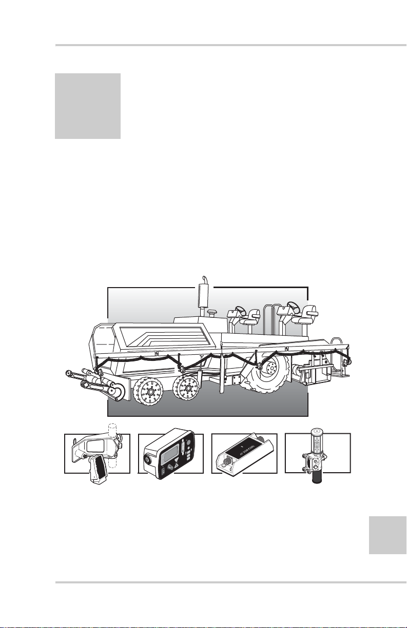
System Overview
System Five™ is a complete, non-contacting control system which
combines both elevation control and slope control into a simple,
easy to use package (Figure 1-1).
The primary function of System Five is to provide screed control so
that the paving material is placed into position at the correct
elevation and slope.
TO
AU
VEY
UR
S
y
g
o
l
o
n
h
c
e
T
e
d
a
r
G
d
e
c
AGTEK
n
a
v
d
A
II
racker
T
onic
S
)
SET
NU
E
(M
ive
F
ystem
S
D
R
A
W
R
O
F
Figure 1-1. Paver System Five Components
P/N 7010-0341 www.topconpositioning.com
1-1
Page 18
System Overview
S
yst
em
F
ive
S
ys
t
e
m
F
i
ve
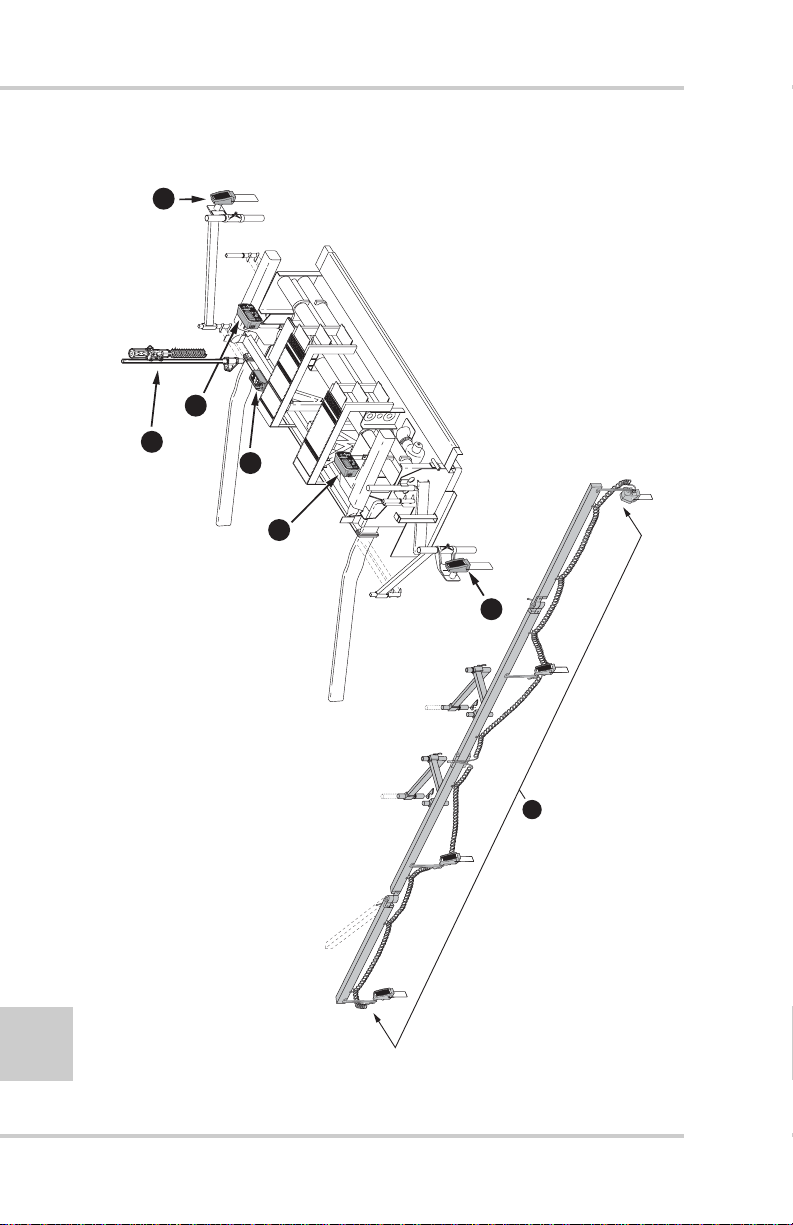
Figure 1-2 displays the setup of components on a screed.
TM
x
o
B
ol
r
t
on
C
ve
i
F
m
e
t
ys
. S
1
)
S
A
S
(
m
e
t
ys
S
TM
ging
a
r
ve
A
c
oni
. S
2
II
r
r
o
s
n
acke
e
r
T
S
c
e
oni
lop
. S
. S
3
4
ack
j
r
acke
r
T
&
r
acke
r
T
r
ase
. L
5
3
EY
V
UR
O
S
T
)
U
U
N
ET
E
S
A
M
(
e
v
i
F
m
e
t
s
y
S
FORWARD
1
5
4
VEY
UR
S
TO
)
T
U
NU
E
E
S
A
M
(
e
v
i
F
m
e
t
s
y
S
1
3
1-2
2
Figure 1-2. Paver System Five Top View
Topcon Paver System Five Operator’s Manual
Page 19
Getting Acquainted
S
ystem
F
ive
Getting Acquainted
A standard System Five Paver system includes two Control Boxes,
two Sonic Trackers and a single Slope Sensor. When setup and
connected, the Control Boxes control either the left or right side of
the machine for either elevation or slope.
Control Box
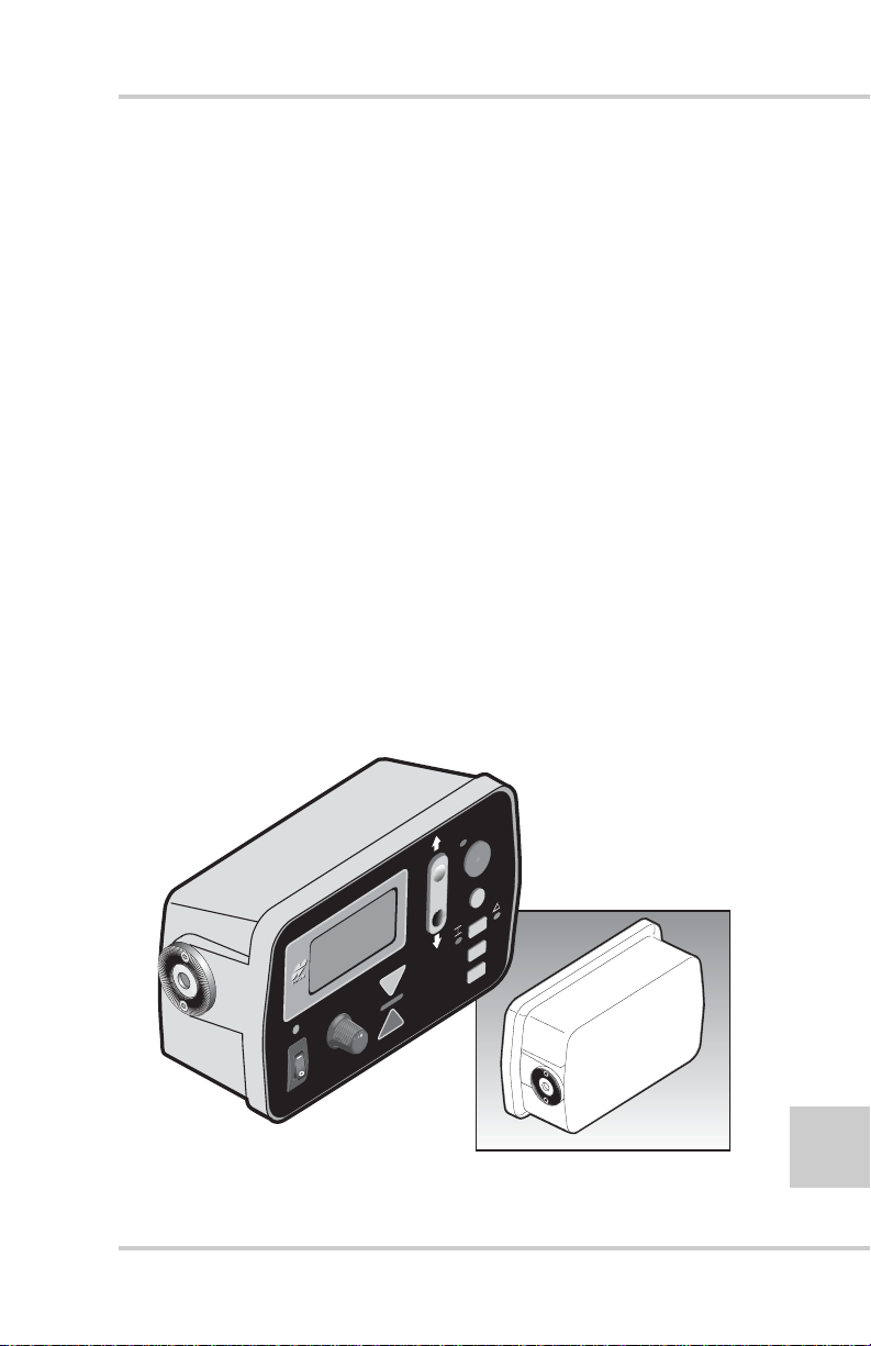
The Control Box (Figure 1-3) is the operator’s interface to
System Five. The Control Box recei ves signals from the sensors
(Sonic Tracker II™, Laser Tracker, and/or Slope Sensor), and
uses these signals to determine if grade or slope corrections are
necessary. If a change in grade or slope is required, the Control
Box sends a signal to the valve controlling the tow point
cylinder on the appropriate side of the machine to raise or
lower, thus maintaining correct mat thickness.
The Control Box connects to the Sonic Tracker II™, the Slope
Sensor, and to the paver through electrical cables. The Control
Box easily attaches to its mounting bracket with one clamp, and
at the end of the day should be removed for storage.
TO
AU
VEY
UR
S
)
SET
NU
E
M
(
ive
F
ystem
S
Figure 1-3. Control Box
P/N 7010-0341 www.topconpositioning.com
1-3
Page 20
System Overview
Sonic Tracker II
The Sonic Tracker II™ (Figure 1-4) measures and controls the
elevations of the screed. A transducer, located in the bottom of
the Sonic Tracker II™, generates sound pulses like a speaker
and listens for returned echoes like a microphone. The Tracker
measures the distance, and controls grade from a physical grade
reference, such as a curb, stringline, or existing road surface. A
bail is used to compensate for rapid air temperature changes. In
paving applications a bail should always be used.
The Sonic Tracker II attaches to the system through one quick
connect cable and attaches to the machine with a single bolt. At
the end of the day, Sonic Tracker II should be removed for
proper storage in the carrying case.
1-4
II
racker
T
onic
S
II
racker
T
onic
S
UND
SO
LSES
U
P
Figure 1-4. Sonic Tracker II
Topcon Paver System Five Operator’s Manual
Page 21

Getting Acquainted
Slope Sensor
The slope sensor (Figure 1-5) is a precision electronic sensor
which functions much like a precision carpenter's level. The
slope sensor reads the inclination (tilt) of the screed and sends
the signal to the Control Box. The slope sensor measures slopes
from +20% to -20%.
The slope sensor connects to each Control Box through an
electrical cable and requires no adjustments, and is the only
component of System Five that can be used to control either
side of the paver. The slope sensor is a sealed component, and
once attached to the Paver, should not be removed.
F
O
R
W
AR
D
-2.0
SLOPE
0.0 %
SLOPE
+2.0
%
SLOPE
%
+
+
+
CONTR
OL BOX L
ISPLAY
D
%
IND
%
IND
%
IND
CD
Figure 1-5. Slope Sensor
P/N 7010-0341 www.topconpositioning.com
1-5
Page 22
System Overview
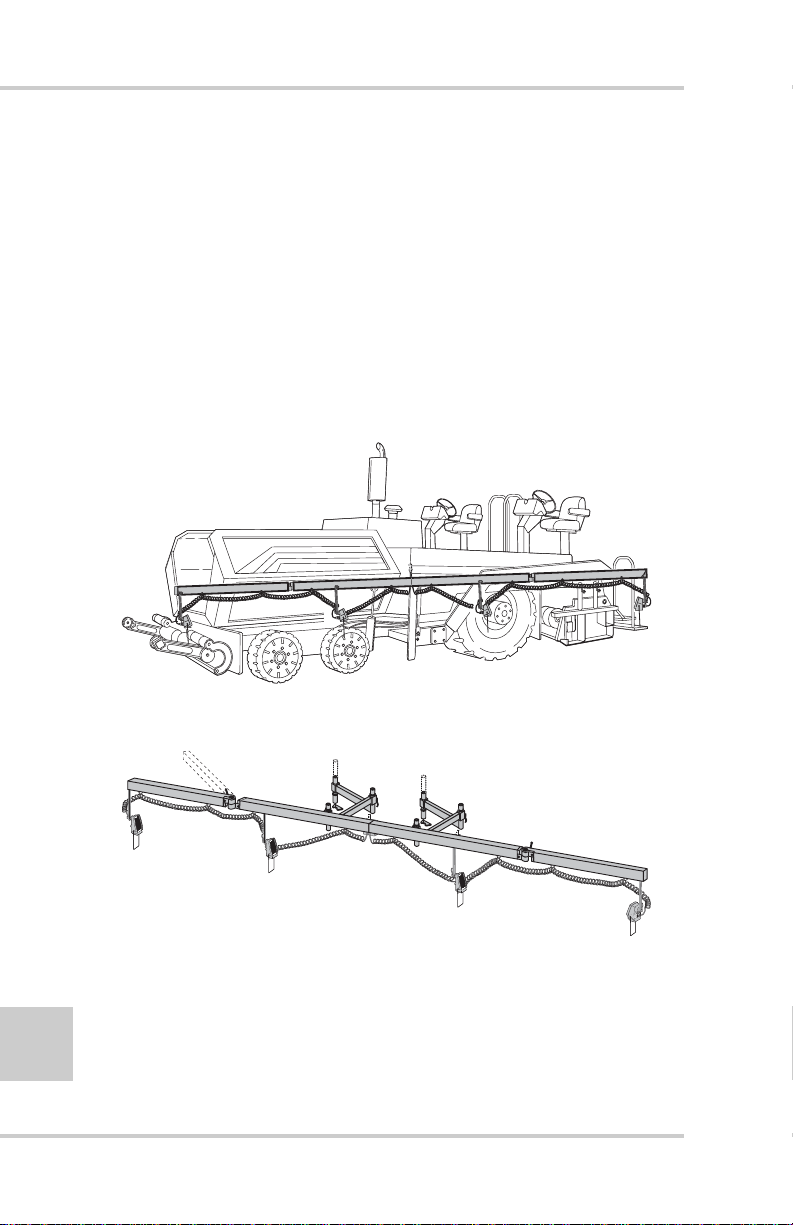
Smoothtrac Sonic Averaging System (SAS)
The Smoothtrac® SAS (Figure 1-6) is an elevation control
system that combines multiple sonic trackers to calculate an
average of the physical reference. Each tracker sends its
distance measurement to the Control Box which then averages
those measurements and sends a correction signal to the tow
point cylinder . The Smoothtrac replaces the mechanical ski that
drags on the ground.
The Smoothtrac connects to the Control Box through the
tracker cable.
1-6
Figure 1-6. Smoothtrac Sonic Averaging System (SAS)
Topcon Paver System Five Operator’s Manual
Page 23
Getting Acquainted
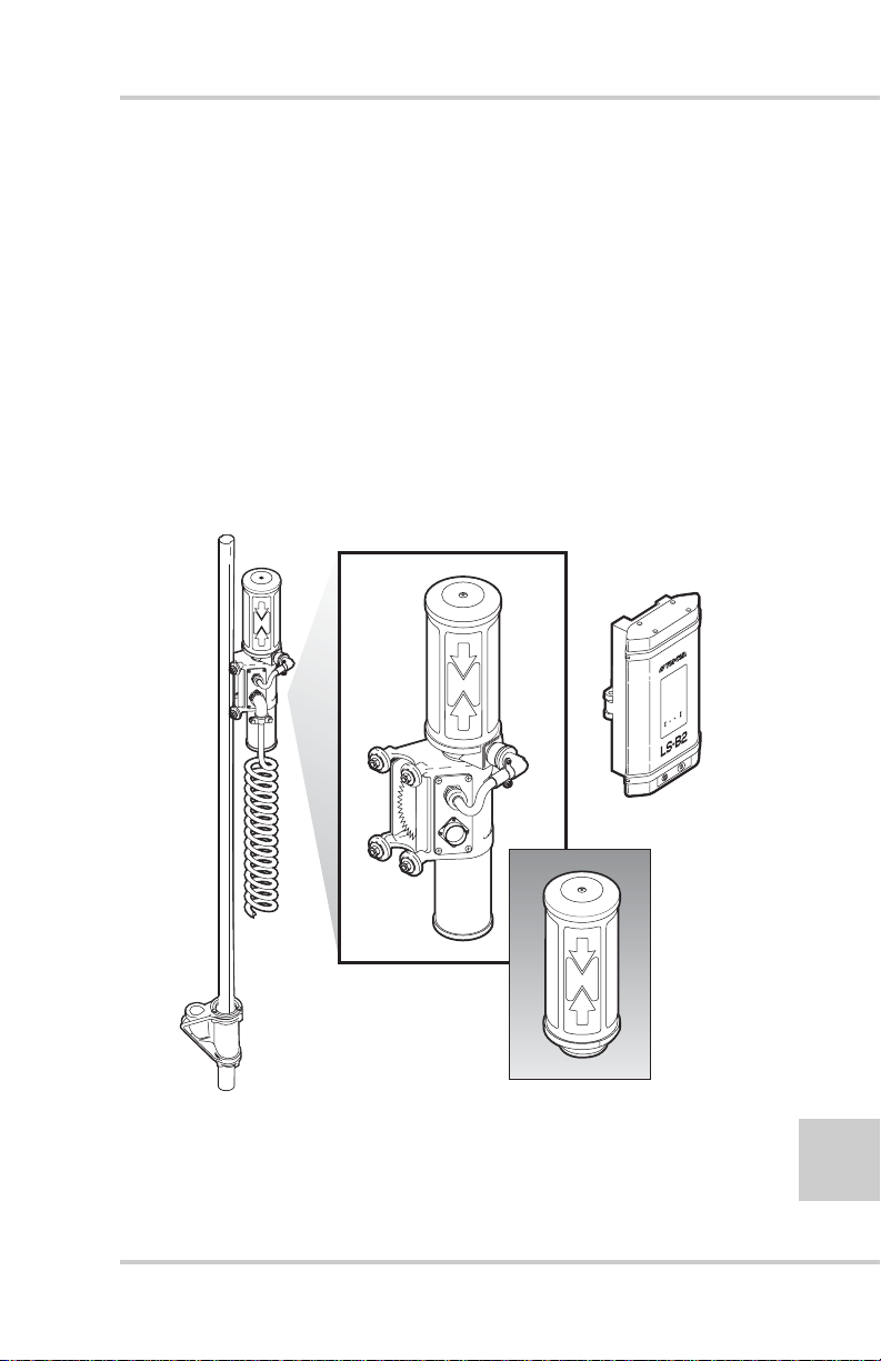
Laser Tracker & Trackerjack
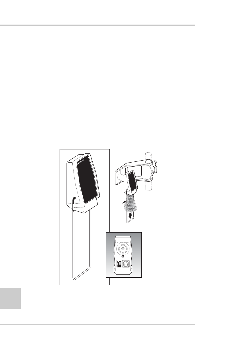
The laser tracker (Figure 1-7) is an elevation control sensor that
measures and controls the elevation of the screed. After
receiving a signal from a rotating laser, the laser tracker sends a
signal to the Control Box, which then sends a raise or lower
signal to the tow point cylinder.
The Trackerjack attaches to the laser receiver and then mounts
to a vibration pole (Figure 1-7). Use the same cable from the
Sonic Tracker II to power the laser tracker/Trackerjack system.
The laser trackerjack should be removed at the end of each day
and stored in its carrying case.
OPTIONAL
LS
-
B
2
4
1 2 3
Figure 1-7. Laser Tracker & Trackerjack
P/N 7010-0341 www.topconpositioning.com
1-7
Page 24

System Overview
Care and Preventive Maintenance
In general, follow these guidelines when using System Five:
• Always clean and thoroughly dry the removable components
before storing them in carrying cases. Use a clean, soft cloth
moistened with a neutral detergent or water.
• Keep carrying cases clean and dry. Do not leave them open and
exposed to the elements.
• Some moisture on the Control Box and its components is
acceptable during working conditions. Do not spray water or
use high pressure steam cleaner hoses directly on cables and
components.
• Use protective connector caps on cables when not using the
System Five for a period of time. Water accumulating on the
connectors can cause electrical shorts.
At the end of the day, performing general maintenance and storing
mobile parts will help to keep the System Five in top condition.
• Remove the Control Box and the Laser T racke r and dust with a
dry or damp non-abrasive, soft cloth.
1-8
• Insert cables into appropriate storage connectors after removing
the Control Box.
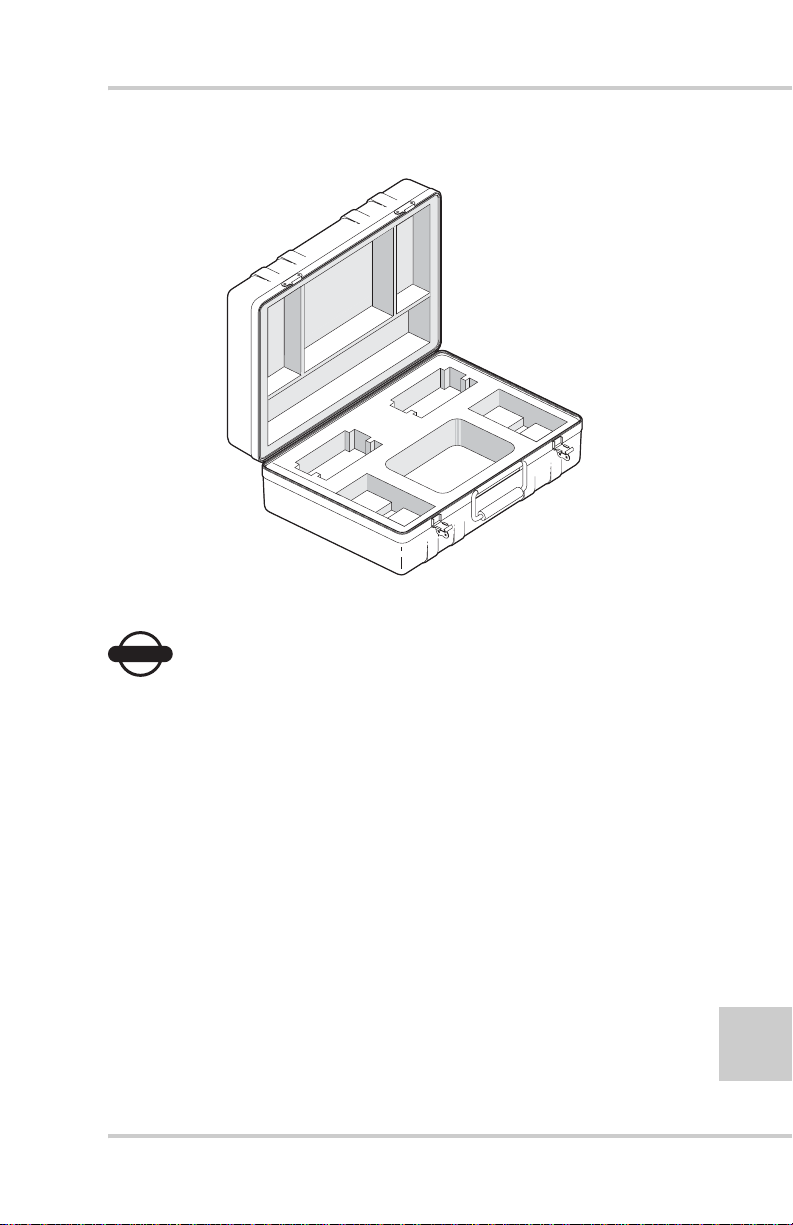
A Carrying Case is provided with each System Five. The Carrying
Case is lined and includes pre-cut sections for each Sonic Tracker II
and the Control Boxes. A cut-out section is also provided for
storing coil cords (Figure 1-8 on page 1-9).
Topcon Paver System Five Operator’s Manual
Page 25
Care and Preventive Maintenance
Figure 1-8. Carrying Case
NOTICE
NOTICE
Keep the carrying case dry and store in a dry
location. Never let the interior of the carrying
case become wet. If the case does become wet,
remove the components and let it dry.
P/N 7010-0341 www.topconpositioning.com
1-9
Page 26

System Overview
Notes:
1-10
Topcon Paver System Five Operator’s Manual
Page 27

Chapter 2
Tractor
Screed
Screed Pivot PointTow Point
Paving Principles &
Control Methods
This chapter describes the components of pavers and the basics in
paving principles, as well as control methods used for paving.
Paver Components
Modern pavers (Figure 2-1) consist of two major units: the Tractor
and the Screed.
The primary function of the tractor is to propel the truck or paver
feeding device, to convey and distribute the paving material and to
tow the screed. The function of the screed is to strike off the
material in preparation for further compaction. The screed is
mounted to the tow arms at the screed piv ot points and is attached to
the paver at the tow points.
Figure 2-1. Paver Components
P/N 7010-0341 www.topconpositioning.com
2-1
Page 28
Paving Principles & Control Methods
How a Screed Works
The screed on all modern pavers is of the “floating, self leveling”
type. As the paver tows the screed unit forward, paving material
flows under the screed. This causes the screed to float on the mat of
material, thus establishing mat thickness. Since the screed is
mounted to the paver only at the tow points, the screed is
completely free to float up or down (Figure 2-2). The screed will
always seek it's own “Planing An gle”, or angle of attack, dependen t
on the combination of forces acting upon the screed (Figure 2-2).
Tow P
oin
t Path
E
xisting
S
urf
ace
2-2
S
cree
d
A
ngl
e o
f
A
tt
ack
Figure 2-2. Tow Point Path and Planning Angle
• If the screed angle of attack is increased the screed rises,
increasing the mat thickness (Figure 2-3).
• If the angle of attack is decreased, the screed will settle,
providing a thinner mat surface (Figure 2-3).
Figure 2-3. Screed Determines Mat Thickness
Topcon Paver System Five Operator’s Manual
Page 29
How a Screed Works
Lengths Travel
Lengths Travel
Lengths Travel
Lengths Travel
Elevation
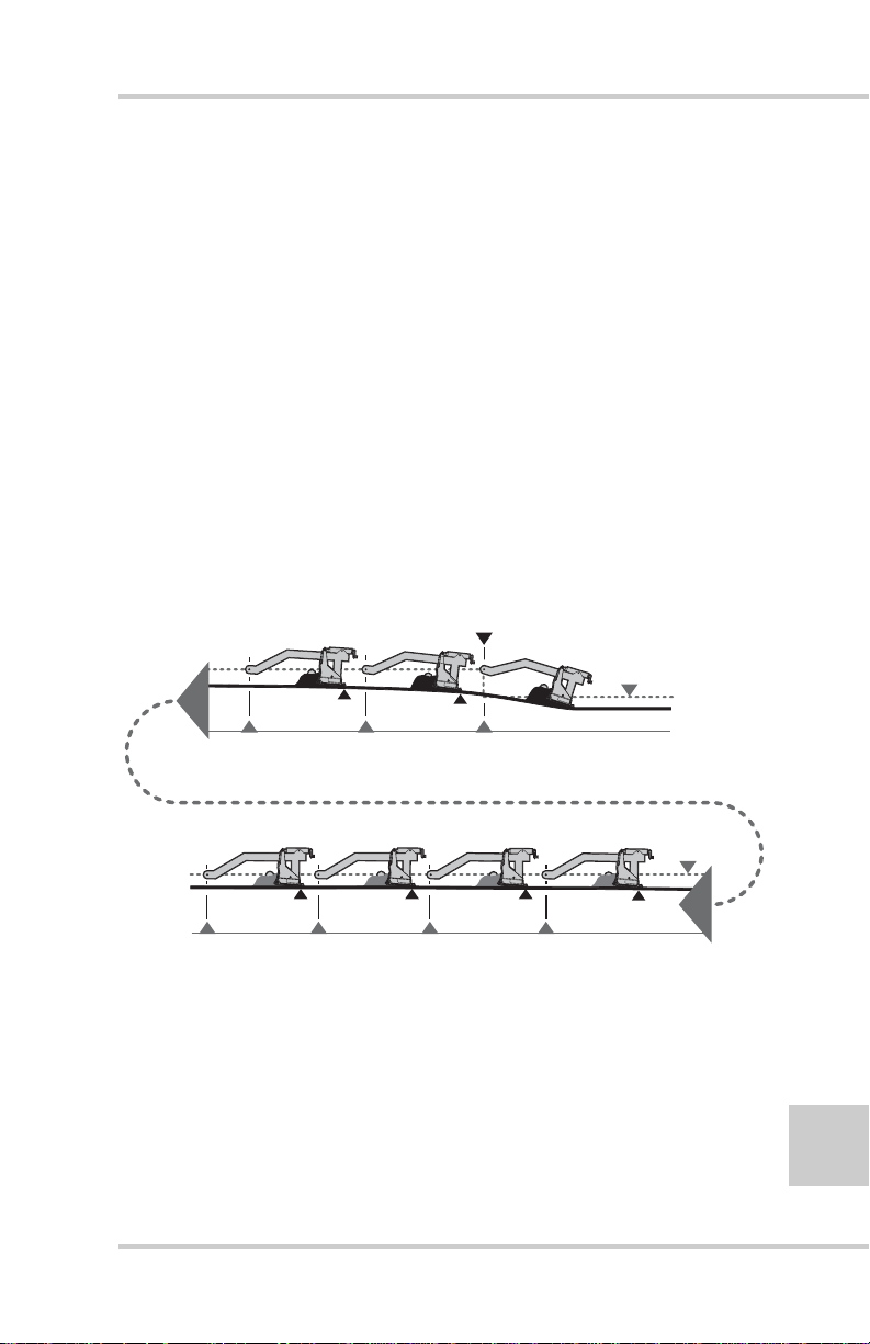
Because the screed floats, it will not immediately react to a change
in the tow point. It needs a certain amount of time or distance to
make a correction in the mat thickness (Figure 2-4).
• If the tow point is changed by a unit of one, the paver must
move one tow arm length before the screed will correct 63% of
the elev ation.
• After 2 tow arm lengths 83% of the correction is made and 3
tow arm lengths would account for 95%.
• It takes 6 tow arm lengths to achieve 100% of the elevation
change.
Considering that 95% of the change takes place after 3 tow arm
lengths, this can be used in practical applications to qualify for full
correction.
Change to
Tow Point Path
Tow Point Path
2 Tow Arm
Lengths Travel
87%
1 Tow Arm
Length Travel
63%
Tow Point Path
98%99%100%
6 Tow Arm
P/N 7010-0341 www.topconpositioning.com
5 Tow Arm
Figure 2-4. Tow Arm Travel
4 Tow Arm
95%
3 Tow Arm
2-3
Page 30
Paving Principles & Control Methods
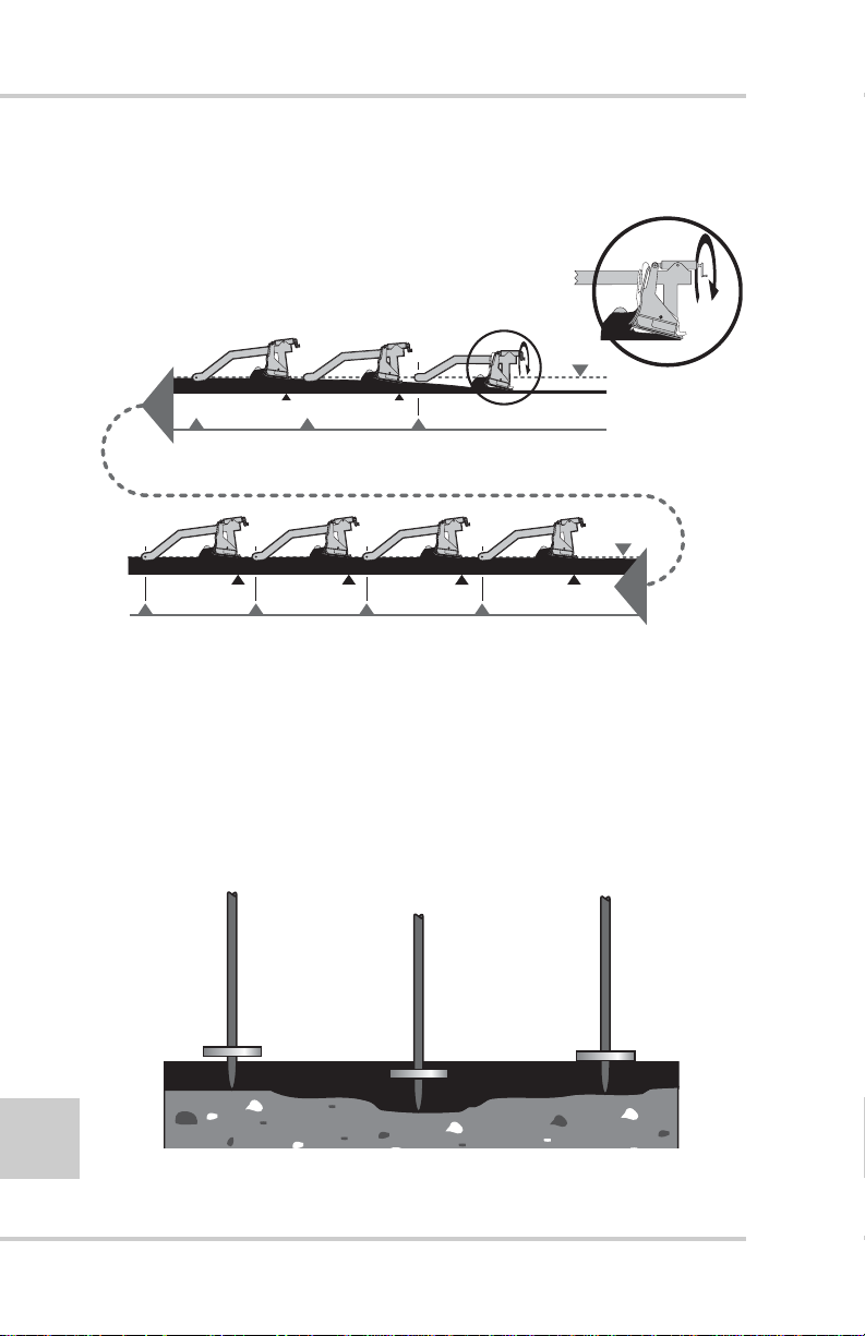
The same is true when making elevation changes with the manual
thickness cranks (Figure 2-5).
Change in Screed
Angle of Attack
from Crank
Tow Point Path
2 Tow Arm Lengths Travel
87%
100%
1 Tow Arm Length Travel
63%
Tow Point Path
99%
4 Tow Arm Lengths Travel5 Tow Arm Lengths Travel6 Tow Arm Lengths Travel
98%
3 Tow Arm Lengths Travel
95%
Figure 2-5. Manually Changing Mat Thickness
Always check mat depth in several locations before making any
elevation corrections. The surface being paved may have wheel
ruts, dips and ridges that will give an untrue indication of overall
mat depth. Check sev eral sp ots t o get an average (Figure 2-6). If an
elevation change is made, wait 3 to w arm lengths for full correction.
T oo much cranking and stabbing will cause raise and lo wer changes
that will produce an uneven mat surface.
2-4
Figure 2-6. Checking Mat Thickness
Topcon Paver System Five Operator’s Manual
Page 31

How a Screed Works
(
Weight of Screed
(Force "P")
The screed has four main forces acting on it at all times, whether
paving in manual or with automatics (Figure 2-7). A change in any
one of the forces will cause the screed to rise or fall, changing the
mat depth. The key to smoother paving is to keep these forces as
constant as possible. The following sections revie w these forces and
the factors that will have an effect on the paving.
(Force "W")
P
Tow Point
Force "P")
Head of
Material
(Force "M")
Figure 2-7. Forces Affecting the Screed
M
W
R
Reaction of Material
Under Screed
(Force "R")
Tow Point Force (“P”)
The tow point force (P) is the resistance to forward travel
(Figure 2-8).
P
Tow Point
Figure 2-8. Tow Point Force (“P”)
The P force will remain constant if the paver is kept mo ving at a
consistent speed at all times. If the paver is allowed to stop, the
screed will settle in the fresh mat and leave a mark. The mark
cannot be fully smoothed out by the roller and a bump will end
2-5
P/N 7010-0341 www.topconpositioning.com
Page 32

Paving Principles & Control Methods
up in the mat that will show up in the profilograph readings.
Changing the speed of the paver will also cause the screed to
rise and fall, affecting the mat thickness.
The optimum paving speed is determined by the depth and
width being paved and the rate at which material can be
delivered to the job . Calculate the tons/hour into feet per minute
(Figure 2-9). Do not start and stop the paver.
Figure 2-9. Travel Speed to Reduce Tow Point Force (“P”)
Truck Exchange, Another Tow Point Force
It is very important that truck exchanges be carried out as
smoothly as possible to avoid disturbing the smooth,
uninterrupted forward motion of the paver. The following
lists some steps to take to avoid disturbance of the paving
operation by trucks.
2-6
1. Stop the mix delivery truck close, but not too short of
the paver. Always allow the paver to pickup trucks on
the run.
2. Never allow the truck to bump the paver. Allowing
trucks to bump the paver when backing up, can drive
the screed into the mat and produces bumps and ridges
which may not roll out.
3. Trucks applying and holding their brakes excessively
while dumping their load may cause the paver to slow,
which in turn will cause the screed to rise. The truck
driver should apply only light pressure on the brakes,
sufficient to maintain contact with the paver.
Topcon Paver System Five Operator’s Manual
Page 33

How a Screed Works
4. Dumping of material in front of the paver as the truck
pulls away after emptying its load into the hopper, can
cause the paver to ride over the pile of material with
subsequent adverse effects on mat quality. Avoid
trucks pulling away prior to completely dumping all
material. Use a dump person to monitor and regulate
truck movements in front of the pav e r.
Head of Material (“M”)
One of the primary functions of the paver tractor is to convey
and distribute paving material onto the ground in front of the
entire width of the screed. This material, once deposited in
front of the screed is the head of material over which the screed
will pass.
One of the keys to smooth paving is to maintain this head of
material as constant as is possible. The resistance to forward
motion exerted by the head of material (M) is one of the major
component of resistance to forward motion (Figure 2-10).
Control of this force is a basic and necessary function of any
paving operation.
Head of
Material
M
(Force "M")
Figure 2-10. Head of Material Force (“M”)
The volume and consistency of the head of material determines
how much paving material flows under the screed and
influences mat thickness and surface texture.
The most common factor affecting force “M”, the head of
material, is incorrectly adjusting the Automatic Feeder
Controls.
P/N 7010-0341 www.topconpositioning.com
2-7
Page 34

Paving Principles & Control Methods
s
th
es
These systems, whether of the “hanging paddle” type or the
sonic sensor type, should be adjusted to operate the auger/
conveyor assemblies 95% to 100% of the time. On/off
operation of the auger system will cause fluctuation in the head
of material.
The highest quality mat will generally result when a constant
head of material is maintained across the entire width of the
screed and the material almost covers the auger shaft. If the
volume of paving material is too high, there is resistance to the
travel of the screed. This causes the screed to rise and can result
in ripples, auger shadows and long waves. It also results in
increased auger wear (Figure 2-11).
C
Indicates Centerline
of Auger
Correct Dep
of Mat
Correct
Head of
Material
C
Maintained
2-8
Screed Rise
Due To
Head of
Material
Too High
C
Increased
Resistance
Screed Settl
Due To
Head of
Material
C
Decreased
Resistance
Too Low
Figure 2-11. Head of Material Affects Mat
Topcon Paver System Five Operator’s Manual
Page 35

How a Screed Works
Reaction of Material Under Screed (“R”)
Ideally, every truck load of material delivered to the paver
would be exactly like every other load, with no variation.
However, as a practical matter, changes in mix characteristics
such as mix temperature, density, gradation, A.C. Content,
segregation, etc., will affect the internal stresses developed
within the mix, which in turn affects the resistance of the mix to
flow under the screed (reaction of material under screed, “R”).
The key element to bear in mind is that the screed passing over
the paving material will compact the material to a certain
degree. Variables in the resistance of the material to compactive
forces will cause changes in the screed's angle of attack, which
in turn will affect mat thickness and therefore mat smoothness
(Figure 2-12).
R
Reaction of Material
Under Screed
(Force "R")
Figure 2-12. Reaction of Material Under Screed
Gradation Mix Characteristics
This aspect of the paving material will vary according to
the intended use of the material as abase course, binder
course or the final wearing surface. Normally, maximum
aggregate size, ratio of aggregates, fines content and most
importantly, asphaltic binder content, is specified by the
contracting agency.
P/N 7010-0341 www.topconpositioning.com
2-9
Page 36

Paving Principles & Control Methods
Adherence to mix design specifications is usually the
responsibility of the material supplier.
Segregation is a material deficienc y caused by a separation
of the larger aggregate sizes from the bulk of the paving
material.
This condition is encountered especially in mixes with
relatively large maximum size aggregate (example: 1" and
larger, the so called “large-particle” mixes). When paving
material is deposited in piles, as in an asphalt plant silo, a
haul truck, a paver hopper, on the ground in front of the
paver in a windrow, or on the ground in the auger chamber,
segregation can and does frequently occur.
2-10
NOTICE
NOTICE
The areas listed above where segregation can
occur are all areas that the material may
encounter before being laid down as a mat.
Therefore, these areas of segregation must be
addressed prior to any paving. The screed
cannot rectify segregation during the paving
process.
Segregation can also be the result of improper hopper
dumping.
During normal operation, the vibration of the pavers hopper
will cause segregation. Therefore, dumping the hopper after
each truck should be avoided because material that has
rolled to the outside of the hopper (the large aggregate) will
fill the conveyors and auger chamber and result in a
segregated area behind the paver with a noticeable
difference in surface texture.
If It Doesn't Look Right, It Isn't Right:
irregularities indicate that the homogeneous characteristics
Surface and texture
Topcon Paver System Five Operator’s Manual
Page 37

How a Screed Works
of the material in the mat have been interrupted, which
usually results in bumpiness and premature failu re of the
pavement in those areas.
Segregation can also be the result of excessively worn
augers: “Center Streak” segregation can be caused by worn
“Kicker Paddles” at the center chain cause or near the
outside auger bearings. In fact center streak segregation is
frequently caused by incorrect arrangement of the auger
segments adjacent to the auger chain case. (Consult the
Manufacturers Manual).
“Center Streak” segregation is also caused by feeder gates
being set to tow. Adjust as necessary to provide sufficient
uniform material at the center of the paver.
NOTICE
NOTICE
“Center Streak” segregation can be limited and
even eliminated by slowing paving speed.
Mix Temperature Characteristics
A common paving problem is inconsistent temperatures in
the asphalt mix. As the material cools it loses its viscosity
making it more difficult to compact. If the resistance to
compaction increases, the screed will naturally increase its
angle of attack and begin to float up. This will change the
mat depth, resulting in bumps in the surface. If the mix and
or screed temperature are too low , the screed may no longer
slide smoothly over the material and a tearing of the mat
will occur.
Simple steps to take to control temperature variations:
1. Ensure that haul trucks take the shortest, most practical
route to the paver. Make certain that all trucks take the
same route to the paver.
2-11
P/N 7010-0341 www.topconpositioning.com
Page 38

Paving Principles & Control Methods
Weight of Screed
2. Make sure that the trucks arrive at the same order in
which they were loaded at the asphalt plant.
3. Ensure that no bunching of trucks occurs at the paver,
with several trucks waiting to dump their loads.
4. Match lay-down rate to material delivery rate.
NOTICE
NOTICE
Temperature problems may occur will before the
time the material is loaded into the trucks, or
during the trip to the paver. They can be the
result of temperature variations at the plant. If
this is not addressed prior to delivery of material
to the paver, waviness in the he mat will be the
result.
Weight of Screed (“W”)
For the weight of screed force “W” to remain constant, the
weight of the screed or the downward pressure exerted by the
screed on the paving material should not change (Figure 2-13).
The weight of the screed is measured in pounds per square inch.
(Force "W")
2-12
W
Figure 2-13. Weight of Screed
Members of the paving crew climbing on and off the screed
will also have some affect on the weight of screed force.
Topcon Paver System Five Operator’s Manual
Page 39

How a Screed Works
The primary factor affecting this force is changi ng the wid th of
the screed (Figure 2-14). Extendible screeds weigh the same
whether they are fully retracted or fully extended. The
difference is the wider the extension of the screed the greater
the surface area of paving material to support. An extended
screed has fewer psi, which means less compaction, causing the
screed to raise.
Figure 2-14. Width of Screed Affects Weight of Screed
Quality of Base Being Paved
There are factors other than the four main forces that can have
an effect on the quality of the mat. An important one is the
quality of the base to be paved. It makes more sense to build
smoothness from the base up, than to try to smooth a road in the
last lift of paving. However, on overlay paving jobs we have to
work with what we have.
Remember that a mat which appears smooth immediately
behind the paver, may actually contain areas of considerably
varying thickness of material as a result of undulations in the
base being paved. Due to the principle of “Differential
Compaction” high spots will not compact as much as the low,
therefore allowing some of the irregularities to be rolled back
onto the mat (Figure 2-15 on page 2-14). To minimize this
problem, lay a leveling course in the lo w spots or pa v e multiple
lifts to average out the irregularities.
P/N 7010-0341 www.topconpositioning.com
2-13
Page 40

Paving Principles & Control Methods
Mat Before Rolling
Mat Before Rolling
Figure 2-15. Differential Compaction
Rolling Techniques
A well laid mat can end up with a poor ride quality if
proper rolling methods are not followed. Consult your
compaction equipment manufacture's manuals and
handbooks on compaction techniques.
Mat After Rolling
2-14
Controlling Mat Quality
The primary purpose of the asphalt paver is to place a
smooth mat of material. The primary function of System
Five is to control the vertical position of the screed in
relation to the surface being paved. Automatic grade and
slope control systems can help tremendously in controlling
mat smoothness but mat quality is also dependent on the
following factors:
• Non-stop, continuous operation of paver
• Constant speed of paver
• Truck exchange
• Head of material
Topcon Paver System Five Operator’s Manual
Page 41

• Mix characteristics
– Gradation
– Segregation
– Mix Temperature
• Screed Compaction
• Quality of Base Being Paved
• Rolling Techniques
Control Methods
NOTICE
NOTICE
Changes in any of these factors will cause a
change in mat thickness, density, surface
appearance and mat quality. If changes must be
made, make them as gradually as possible.
Abrupt changes in any of the above factors will
produce rapid changes in mat thickness,
adversely affecting mat quality.
Control Methods
The following sections describe the three types of control possible
with the Pave System Five: sonic, laser, and slope.
Sonic Control
The Sonic Tracker II™ measures and controls the elevation of
the screed, controlling grade from a physical grade reference,
such as a curb, stringline, or existing road surface.
A transducer, located in the bottom of the T racker, generates 39
sound pulses per second and listens for returned echoes like a
microphone. As soon as the Tracker sends out a sound wave, it
starts a stop watch. The sound waves go down, bounce off of a
physical reference, and reflect back to the Tracker. The Tracker
measures the time it takes for the sound wave to return to the
2-15
P/N 7010-0341 www.topconpositioning.com
Page 42

Paving Principles & Control Methods
STOPWATCH
Tracker. Knowing the speed of sound, the Tracker accurately
calculates the exact distance to the grade reference
(Figure 2-16).
E
c
ho
B
oun
T
ransducer Generates
S
ound Pul
se
P
hysical Grad
ces Off
e
R
eference
T
r
acke
C
alculate
r
U
ses Ec
D
istan
ho's
R
ce To Grad
eturn Time To
e
R
eference
2-16
II
racker
T
onic
S
Figure 2-16. Timed Sound Pulses Determine Distance
II
racker
T
onic
S
Working Window and Sonic “Footprint”
Built into the Tracker is an operational zone, or Working
Window, 2.4 inches above and below the grade reference
(Figure 2-17 on page 2-17). The grade lights on the Sonic
Tracker and Control Box continuously display this grade
information to the operator.
Topcon Paver System Five Operator’s Manual
Page 43

E
NO CORRECTION
W
MADE
(OUT OF
ORKING WINDOW)
COARSE
CORRECTION
(AUTOMATIC)
FINE
CORRECTION
(AUTOMATIC)
2.4''
2.4''
S
onic Tracker
II
SLOW BLINKING UP ARROW
SOLID UP ARROW
BLINKING UP ARROW
BLINKING UP ARROW/ON GRADE
ON GRADE
BLINKING DOWN ARROW/ON GRAD
BLINKING DOWN ARROW
SOLID DOWN ARROW
SLOW BLINKING DOWN ARROW
Control Methods
Figure 2-17. Sonic Tracker Working Window
When setting up the Tracker o ver a grade reference, the size
of the Sonic Cone or the “footprint” needs to be considered
(Figure 2-18 on page 2-18). As an example, at about 2 feet
from the tracker, you will have a footprint or cone of about
6 inches.
As the Tracker is positioned closer to the grade reference
the working footprint decreases in size. As the Tracker is
moving farther away from the grade reference the sonic
footprint or cone will increase in size.
2-17
P/N 7010-0341 www.topconpositioning.com
Page 44

Paving Principles & Control Methods
SONIC "FOOTPRINT"
24"
S
onic Tracker
II
6.0"
2-18
Figure 2-18. Sonic Tracker “Footprint”
Sonic Tracker Operation and its Position
On the paver, the Sonic Tracker II will be positioned above
the grade reference to maintain an exact distance from the
tracker to the reference (Figure 2-19 on page 2 - 19). If the
Tracker is on-grade, the mat being laid will be at the
desired depth.
Topcon Paver System Five Operator’s Manual
Page 45

Control Methods
STOPWATCH
STOPWATCH
On
S
onic Tracker
II
II
racker
T
nic
o
S
Grade
Figure 2-19. Sonic Tracker On-Grade
If the screed and the Sonic Tracker II start to raise, the
watch stops at a longer time (Figure 2-20). The Tracker and
Control Box will indicate a down correction arrow, and
lower hydraulic valve corrections are applied to bring the
Tracker back to on-grade.
S
onic Tracker
II
II
r
ke
rac
T
onic
S
Grade
On
Figure 2-20. Sonic Tracker above Grade
P/N 7010-0341 www.topconpositioning.com
2-19
Page 46

Paving Principles & Control Methods
If the screed and Sonic Tracker II are lowered, the watch
stops at a shorter time (Figure 2-21). The Tracker and
Control Box indicate a raise correction arrow, and raise
hydraulic valve corrections are applied to bring the Tracker
back to on-grade.
S
onic Tracker
II
II
ker
rac
T
onic
S
Figure 2-21. Sonic Tracker Below Grade
Grade
STOPWATCH
On
2-20
If the Sonic Tracker II is side shifted off a stringline, the sound
waves reflect off the ground and the Tracker's stopwatch
indicate a longer time (Figure 2-22 on page 2-21). The Tracker
is out of the Working Window, and no on-grade corrections are
applied.
Topcon Paver System Five Operator’s Manual
Page 47

Control Methods
STOPWATCH
S
onic Tracker
II
II
racker
T
ic
on
S
Grade
On
Figure 2-22. Sonic Tracker Scanning Outside of Stringline
If the Tracker sees an obstruction closer than the reference
signal, such as a grade pin, the watch stops at an even
shorter time (Figure 2-23). The Tracker is out of the
Working Window, and no on-grade correction signals are
applied.
STOPWATCH
S
onic Tracker
II
II
racker
T
ic
on
S
Grade
On
Figure 2-23. Obstructions within the Sonic Tracker’s Working Window
P/N 7010-0341 www.topconpositioning.com
2-21
Page 48

Paving Principles & Control Methods
STOPWATCH
T
STOPWATCH
Sonic Tracker and Temperature Changes
Since temperature affects the speed of sound, the tracker
has a built in temperature sensor for applications with
gradual temperature changes such as on graders or dozers.
In paving applications you can get a more dramatic and
rapid change in air temperature. To compensate for these
variations a temperature bail is positioned below the
tracker.
When the Sonic Tracker’s transducer emits a sound wave,
the tracker records the time to the bail and continues to
listen for the grade reference. If a temperature variation
occurs, such as heat off a freshly paved mat, a difference in
time to the temperature bail is recorded. The correction for
the speed of sound is then applied to the grade reference
signal, preventing a change in mat depth. The tracker
corrects for temperature variations with every sound wave,
39 times per second. Figure 2-24 illustrates this concept.
2-22
On Grade
arget Reference
Temperature Bail
Target Reference
S
onic Tracker
II S
Heat Induced
Target Error
On Grade
Wind Blown Heat
Freshly Paved mat
Off of
Temperature Bail
Heat Induced
Target Error
onic Tracker
II
Figure 2-24. Working with Sonic Trackers and Temperature Changes
Topcon Paver System Five Operator’s Manual
Page 49

Control Methods
In the upper right hand corner of the Sonic Tracker II
faceplate is a small symbol used to represent the use of the
temperature bail. The LED symbol automatically
illuminate when the bail is connected to the tracker. The
tracker is cast with holes on each side for the bail to snap
and lock into place (Figure 2-25).
II
racker
T
onic
S
T
T
S
onic Tracker
II
Figure 2-25. Sonic Tracker and Components
P/N 7010-0341 www.topconpositioning.com
2-23
Page 50

Paving Principles & Control Methods
Laser Control
For Laser Control a laser transmitter is used to produce a plane
of light which becomes the grade control reference for the job
site. The laser receiver will control the screed to lay a mat
parallel to the laser beam reference.
When the laser beam is in the center of the receiver, it indicates
an on-grade signal (Figure 2-26).
+
2-24
Figure 2-26. Laser Control – On-Grade
As the screed is raised, the beam of light hits the laser receiver
below the center and a lower signal is indicated (Figure 2-27 on
page 2-25).
Topcon Paver System Five Operator’s Manual
Page 51

Control Methods
+
Figure 2-27. Laser Control – Above Grade
As screed is lowered the beam of light hits the Laser Receiver
above the center a raise signal is indicated (Figure 2-28).
+
Figure 2-28. Laser Control – Below Grade
P/N 7010-0341 www.topconpositioning.com
2-25
Page 52

Paving Principles & Control Methods
Slope Control
System Five uses a slope sensor mounted to the transducer
beam on the paver to measure and control the slope of the mat
being laid (Figure 2-29). The sensor contains an electronic level
vial, that acts as a “precision carpenter's le vel”. Slope control
with this electric level vial is very accurate and repeatable.
2-26
2% Slope
Figure 2-29. Position of Slope Control on Paving System
Topcon Paver System Five Operator’s Manual
Page 53

Control Methods
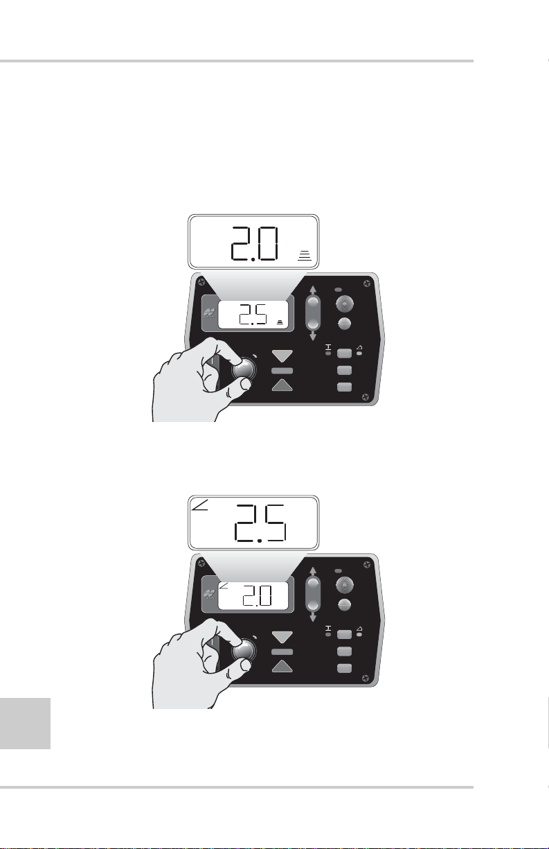
If the required slope changes, the screed operator dials the new
slope into the System Five Control Box (Figure 2-30). The tow
point cylinder on the slope side will raise or lower until the
slope sensor measures the new slope.
2.5% Slope
AU
TO
+
%
SURVEY
FiveSystem
SET
(MENU
)
Figure 2-30. System Five Box directing the Slope Sensor position
P/N 7010-0341 www.topconpositioning.com
2-27
Page 54

Paving Principles & Control Methods
Notes:
2-28
Topcon Paver System Five Operator’s Manual
Page 55

Chapter 3
Stringline Setup
Sonic Stringline provides an inexpensive, easy to set up, continuous
reference that takes the best advantage of the non-contacting feature
of the Sonic Tracker II™. Stringline takes a few minutes to setup,
and becomes a constant grade reference. The stringline also
becomes a visual reference for the job, allowing any mistakes in a
hub elevation to be quickly spotted by sighting down the string.
Sonic stringline is both a reference and an averaging solution.
• As a reference, surface and elevated stringline provides
consistent results for level and sloped surfaces.
• As an averaging solution, surface stringline takes the place of
averaging skis.
The sonic stringline setup consists of readily available materials and
up to 500 feet of nylon stringline. Topcon’s Sonic Tracker II works
with many sizes and types of stringline, for best results use an 1/8
inch diameter nylon stringline.
NOTICE
For a review of how the Sonic Tracker II works, see “Sonic
Control” on page 2-1. If the Sonic T racker tracks the ground but not
a 1/8 inch diameter stringline, clean or replace the transducer. See
Chapter 7 for this procedure.
P/N 7010-0341 www.topconpositioning.com
NOTICE
Using steel wire or a plastic coated stringline
with a smooth surface can provide erroneous
results.
3-1
Page 56

Stringline Setup
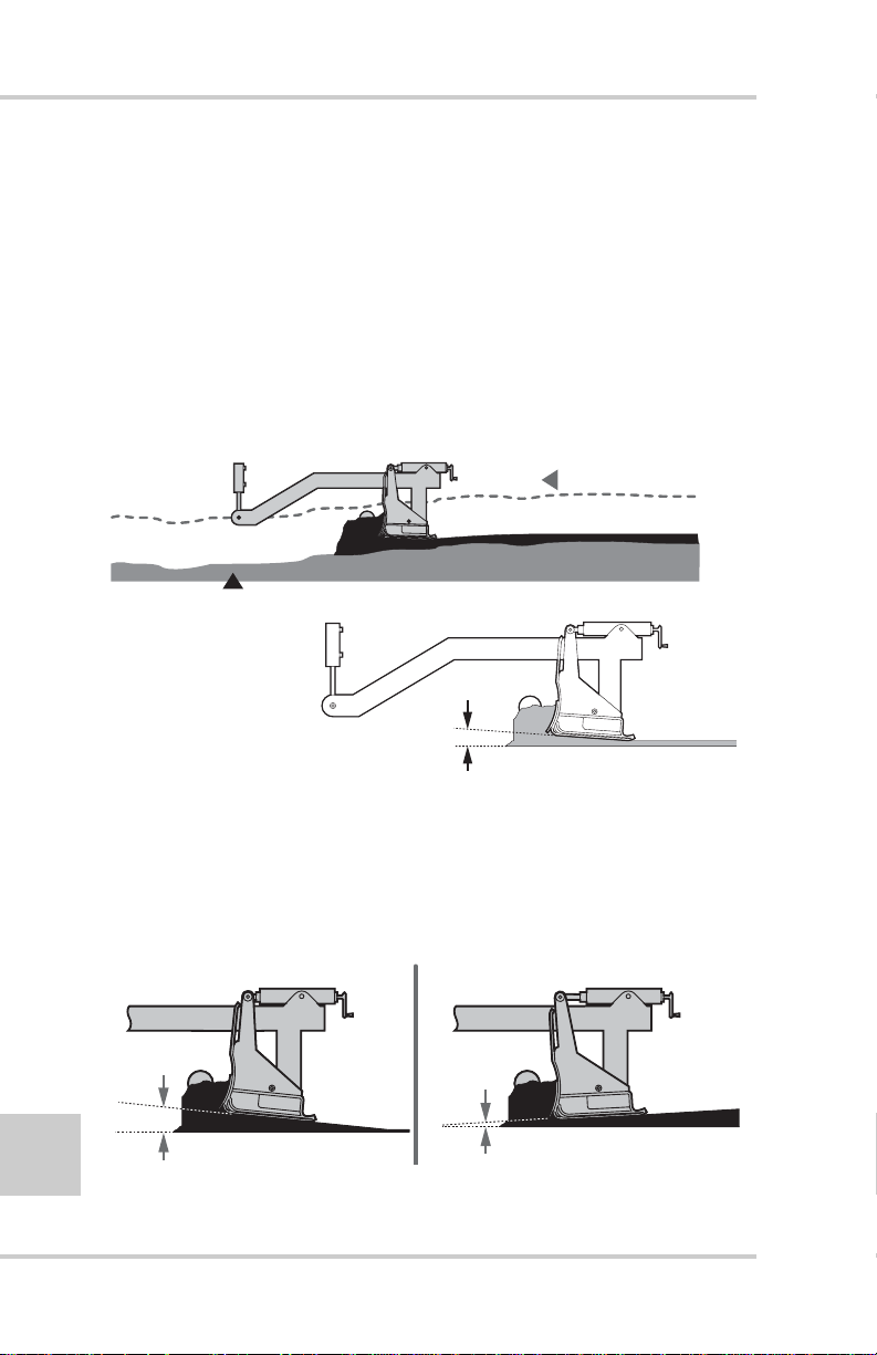
Setting Surface Stringline
Surface stringline provides a low-impact reference and averaging
solution for steering and grade control. Because it rests close to the
surface, trucks and other traffic can dri ve ov er the stringline without
causing control problems and reference damage.
As a grade reference, Pavers use the Sonic Tracker II to track the
stringline, producing a consistent and constant cut. When si ghting
down the stringline, problem areas can be spotted, and marked or
fixed, before paving begins.
Surface stringline replaces a contacting averaging ski when a
reference is unavailable or impractical. Averaging skis average out
the irregularities of the surface being cut, but can be impractical,
bulky, complex, and fragile. Surface stringline is simple, more
practical, and easier to maintain than an averaging ski. When
stretched over the ground, surface stringline levels the high places
and bridges the low (Figure 3-1), creating a natural average over a
distance as long as 500 feet.
3-2
Surface String
Low Spot High Spot
Figure 3-1. Surface String Averaging
Surface stringline is a verifiable reference for any job, replacing
cumbersome av eraging skis. In coordination with the Sonic T rack er
II, stringline acts as 5 to 500 foot long, virtual, and more accurate,
averaging ski.
Sometimes, the surface to be milled contains pot holes or surfaces
too broken to use as a joint match reference Setting elevated
stringline would be too time consuming, especially for small,
divided projects. In these applications, surface stringline pro vides a
simple, easy alternative.
Topcon Paver System Five Operator’s Manual
Page 57

Setting Surface Stringline
Position the tracker 14 to 18 inches above the stringline
(Figure 3-2).
T
S
onic Tracker
II
14"
to
18"
Figure 3-2. Position of Tracker in Correlation to Stringline
NOTICE
NOTICE
It is important to use a stringline with a diameter
at least 1/8” thick. The sonic tracker can detect a
smaller diameter stringline, but when stretched
on the surface to be paved the surface below the
stringline will be within the working window so
you want to make sure you have a strong return
signal.
P/N 7010-0341 www.topconpositioning.com
3-3
Page 58

Stringline Setup
To setup surface string in two simple steps:
1. Drive a concrete nail into the existing surface to be cut
(Figure 3-3) and tie the stringline to the concrete nail.
Figure 3-3. Setup Concrete Nails
3-4
2. Roll out the stringline to the desired length. Pull tight and
secure to another nail at the opposite end. The tightened
stringline rests on top of the existing surface (Figure 3-4).
Figure 3-4. Stringline Reference
• When the sonic tracker sends out a sound wave, the first
thing the tracker sees will be the reference stringline.
Topcon Paver System Five Operator’s Manual
Page 59

Setting Elevated Stringline
• Since the stringline is pulled tight, any small irregularities
in the existing surface will be spanned (Figure 3-5).
Figure 3-5. Stringline Spans Surface Irregularities
As a verifiable grade reference, potential problems can be pointed
out to the inspector before paving.
Setting Elevated Stringline
On some projects the asphalt must be laid to a specified elevation.
For this application an elevated stringline must be set. Elevated
stringline is positioned 1–2 feet above the finished grade using
referencing hubs or lath placed by the surveyor (Figure 3-6).
Figure 3-6. Elevated Stringline
Once positioned, the Sonic Tracker II tracks the stringline,
providing a verifiable slope and cut reference.
NOTICE
NOTICE
Do Not disturb the hubs.
P/N 7010-0341 www.topconpositioning.com
3-5
Page 60

Stringline Setup
B
S
C
Your local Topcon dealer carries the following supplies for setting
elevated stringline:
• Sonic Stringline, 1000’ roll (p/n 7020-0101)
• Sonic Grade Clips, box of 100 (p/n 7020-0121)
• Cut/fill Offset Tap, feet/tenths (p/n 7000-1026)
• Cut/fill Offset Tap, metric (p/n 7000-1027)
Although Topcon’s Sonic Tracker will work with many sizes and
types of stringline, for best results use an 1/8 inch diameter nylon
stringline. Using steel wire or a plastic coated stringline with a
smooth surface can cause erroneous results.
1. Place the Sonic Grade Clips on stakes and drive the stakes
approximately 6 to 8 inches away from, but in line with, the
hubs—Do Not disturb the hubs (Figure 3-7).
LIP
STAKE
6.0" to 8.0"
ALIGN STAKES
3-6
2. Using an anchor pin at each end, roll out the Sonic Stringline
WITH HUB
Figure 3-7. Place Clips and Position Stakes
GRADE
STAKE
HU
the length of the working area and pull the stringline tight.
Topcon Paver System Five Operator’s Manual
Page 61

Setting Elevated Stringline
M
3. After the stringline has been pulled tight, place it into the
“fingers” of each Sonic Grade Clip (Figure 3-8).
Figure 3-8. Place Stringline in Clip
4. Decide what the Sonic Stringline hike-up (the distance from
Finished Grade to the Sonic Stringline) should be; in this
example, two feet.
Making a Cut/Fill Lath
Once you have the stringline setup, fine-tune the height of the
stringline above the grade. To do this, make a cut/fill lath using
a lath and a Topcon Cut/Fill Decal.
1. Assemble the required number of laths for the job.
2. Measure from the bottom of the lath to the desired height
above grade, and make a mark at that point. Place the Cut/
Fill Decal on the lath with “0” at the marked point
(Figure 3-9).
LATH
2.0'
BOTTOM
Figure 3-9. Measure Height Above Grade and Place Cut/Fill Decal
P/N 7010-0341 www.topconpositioning.com
LATH
011
SET "0" ON DECAL
AT 2.0' MARK FRO
BOTTOM OF LATH
3-7
Page 62

Stringline Setup
3. Set the cut/fill lath on the hub and read the cut or fill from
the grade stake next to the hub. Adjust the clip up or down
until the stringline crosses the cut/fill lath at that point
(Figure 3-10).
E
A
cut o
f
.25
feet
2
CU
L
.
1
.
0
1
.
2
.
3
.
T/FILL
H
T
A
L
B
FILL
R
CU
E
U
=
D
E
=
T
G
ST
RAD
AK
CU
.
E
T
25
3-8
Figure 3-10. Adjust Clip and Stringline to Desired Cut/Fill
The stringline is now set to 2 feet above finished grade.
4. Repeat step 3 on page 3-8 at each station before starting to
cut (Figure 3-11).
2.0'
2.0%
2.0' OFFSET
Figure 3-11. Stringline Set at Desired Elevation
Topcon Paver System Five Operator’s Manual
Page 63

Setting Elevated Stringline
Hub
Attaching Stringline to the Grade Stake
Some jobs may require the stringline to be secured directly to
the grade stake rather than attached to the clip.
1. Mark the lath with the desired “hike-up” above grade
(Figure 3-12).
2
V
2. Secure an anchor pin at each end of the stringline and pull
the stringline tight.
3. At each station, staple or Ty-Wrap the stringline directly to
the witness lath at the desired “hike-up” (Figure 3-13).
2
V
2
V
Figure 3-12. Mark Lath with Hike-up Height
2
V
2
V
Hub
Hub
2
V
Figure 3-13. Stringline Attached to Lath
4. Due to the height of some stakes, raise the Tracker or cut
off the tops of the stakes.
P/N 7010-0341 www.topconpositioning.com
3-9
Page 64

Stringline Setup
2.0% SLOPE X 2.00' OFFSET = .04'
R
Setting Projected Slope Stringline
Jobs with slope transitions or super-elevations will have the
stringline set to the “projected slope. ” As the profiler cuts, the Sonic
Tracker and mill follow the slope of the job, preventing elevation
errors at the edge of the road as the slope changes.
To set the stringline to the projected slope,
1. Set up the string at the desired elevation as shown in “Setting
Elevated Stringline” on page 3-5.
2. Raise or lower the stringline to compensate for the percentage
of slope and the distance from the edge of the road to the
stringline:
Rise Run SlopePercentage×=
• If the road rises away from the stringline, the stringline will
need to be lowered (Figure 3-14).
3-10
PROJECTED SLOPE
2.0'
2.0%
2.0' OFFSET
Figure 3-14. Lower Stringline: 2% Cross Slope with 2 Foot Offset
Topcon Paver System Five Operator’s Manual
LOWE
.04'
Page 65

Setting Projected Slope Stringline
3.0% SLOPE X 2.00' OFFSET = .06'
E
• If the road slopes down from the stringline, the stringline
will need to be raised (Figure 3-15).
RAIS
PROJECTED SLOPE
2.0'
2%
.06'
3.0% SLO PE
Figure 3-15. Raise Stringline: 3% Cross Slope with 2 Foot Offset
2.0' OFFSET
3. Repeat step 2 for each station.
3-11
P/N 7010-0341 www.topconpositioning.com
Page 66

Stringline Setup
Verifying Grade
Verifying grade requires measuring the distance from the cut
ground to the Sonic Stringline. To check grade, use a Grade
Checking Lath to check the levelness and depth of cut with the
Sonic Stringline.
The following figures show an example of a hub offset of 1.5 feet
from the edge of the road, and a hike-up of 2.0 feet.
1. Construct a Grade Checking Lath using a lath, a level bubble,
nails, and standard hand tools as shown in Figure 3-16.
TY-WRAP OR TAPE
LEVEL BUBBLE TO LATH
1.5'
NAILS
1.5'
3-12
2.0'
Figure 3-16. Grade Checking Lath
Topcon Paver System Five Operator’s Manual
Page 67

Verifying Grade
2. Set the Grade Checking Lath on the edge of the newly cut
ground so the level bubble extends over the Sonic Stringline
(Figure 3-17).
'
5
.
1
STRINGLINE
STRINGLINE
FI
NISHED GRAD
APPR
OX. .05' TOO HIG
E
H
Figure 3-17. Check Finished Grade
NISHED GRADE (CORRECT
FI
)
3. Tilt the Grade Checking Lath to center the level bubble.
Finished grade is correct if the level just touches the Sonic
Stringline (Figure 3-17).
P/N 7010-0341 www.topconpositioning.com
3-13
Page 68

Stringline Setup
Notes:
3-14
Topcon Paver System Five Operator’s Manual
Page 69

Chapter 4
Operation & Menu
Settings
System Five™ uses a Control Box and Sonic Trackers to produce
exceptional paving solutions. This chapter describes using the
various components, including:
• The buttons, knobs, and switches on the Control Box.
• How to change settings, access information, and take readings
using the various buttons, knobs, and switches.
• The menus available in the Performance Menu.
• How to access, change settings, and apply features using the
Performance Menu.
• How the Sonic Tracker II™ works.
NOTICE
P/N 7010-0341 www.topconpositioning.com
NOTICE
When operating in rainy weather or in wet
conditions, the Control Box, Sonic Tracker II, and
cables must be thoroughly dried BEFORE
placing them in the Carrying Case at the end of
the day.
Any moisture in the Carrying Case will cause
condensation on the inside of the components
which may severely affect accurate operation during
the next paving application.
4-1
Page 70

Operation & Menu Settings
Control Box
The Control Box is the operator’s interface to System Five™
(Figure 4-1), receiving signals from the sensors, and using these
signals to determine if grade or slope corrections are necessary. If
the paving requires a change in grade or slope, the Control Box
sends a signal to the valve controlling the tow point cylinder on the
appropriate side of the paver to raise or lower, thus maintaining
correct mat thickness. The operator can control and monitor the
slope and thickness of the mat using the buttons and displays
located on the front panel of the Control Box.
4-2
Figure 4-1. 9256 Control Box
1. LCD
2. Light Sensor for LED Display
3. Power Switch
4. Grade Adjustment Knob
5. Grade Adjustment LED
6. Set (Menu) Button
Topcon Paver System Five Operator’s Manual
7. Cross Communication Button
8. Slope/Elevation Button
9. Survey Button
10. Auto/Manual Button
11. Jog Button
Page 71

Control Box
LCD
The LCD (Liquid Crystal Display) allows the operator to view
text and graphic symbols that represent elevation or slope
settings that System Five
TM
currently maintains for the paver
(Figure 4-2).
Figure 4-2. LCD Display
Light Sensor for LED Display
The light sensor monitors ambient light to adjust the brightness
of the LED display for better visibility.
The light sensor is located above the power switch.
Power Switch
The power switch (Figure 4-3) for the System Five Control Box
turns it on and off.
O
N
OFF
Figure 4-3. Power Switch
P/N 7010-0341 www.topconpositioning.com
4-3
Page 72
Operation & Menu Settings
Grade Adjustment Knob
The grade adjustment knob makes measured adjustments to
elevation and slope settings, or cycles through menu options.
• Knob adjusts the grade height while in elevation control
(Figure 4-4).
AU
TO
SURVEY
4-4
FiveSystem
SET
(MENU
)
Figure 4-4. Adjusting Grade Height
• Knob adjusts the percentage of slope while in cross slope
control (Figure 4-5).
+
%
AU
TO
+
FiveSystem
Figure 4-5. Adjusting Cross Slope Control
%
SURVEY
SET
(MENU
)
Topcon Paver System Five Operator’s Manual
Page 73

Control Box
Grade Adjustment Direction Arrows
The grade adjustment arrows are located at the upper left and
upper right of the grade adjustment knob.
These two arrows (Figure 4-6) light up in red to indicate the
direction to turn the knob to reach on-grade.
R
otate
K
R
eac
nob
h Grad
e
C
ounterclockwise
To
Figure 4-6. Grade Adjustment Direction Arrows
R
otate
C
lockwi
R
eac
K
nob
se To
h Grad
e
Grade Adjustment LEDs
The grade adjustment LEDs (Figure 4-7) indicate raise, ongrade, and lower information and corrections.
Figure 4-7. Grade Adjustment LEDs
Table 4-1 describes grade adjustment LED indications.
Table 4-1. LED Indications for Elevation/Slope Control
LED Display
Slowly blinking,
yellow down
arrow
Solid yellow
down arrow
Blinking yellow
down arrow
LED
Elevation
Description
Out of range;
beyond .2’ above
grade
Above grade;
between .05' and .2'
Above grade;
between .02
' and
.05'
P/N 7010-0341 www.topconpositioning.com
Slope Description
Beyond 2% above
grade
Above grade,
between 1% and 2%
Above grade,
between .5% and
1%
4-5
Page 74

Operation & Menu Settings
Table 4-1. LED Indications for Elevation/Slope Control (Continued)
LED Display
Blinking yellow
down arrow w/
green bar
Blinking green
bar
Blinking red up
arrow w/ green
bar
Blinking red up
arrow
Solid red up
arrow
Slowly blinking
red up arrow
LED
Elevation
Description
Within .02
On grade On grade
Within .02
Below grade;
between .02
.05
Below grade;
between .05
Out of range;
beyond .2
grade
' of grade
' of grade
' and
'
' and .2'
' below
Slope Description
Within .5% of grade
Within .5% of grade
Below grade,
between .5% and
1%
Below grade,
between 1% and 2%
Beyond 2% below
grade
Function Indicator LEDs
The function indicator LEDs (Figure 4-8 on page 4-7) are
located below the jog button and next to the slope/elevation,
cross communication, and set/menu buttons:
4-6
• CON – indicates the box is in Control Mode.
• SUR – indicates the box is in Survey Mode.
• ELEV – indicates the LCD displays the current elevation.
• AVG – indicates the LCD displays the calculated average
elevation.
Topcon Paver System Five Operator’s Manual
Page 75

Control Box
S
F
unct
I
ndicator
LE
D
s
ion
UR
C
O
ELEV
A
VG
N
SET
(MENU)
Figure 4-8. Function Indicator LEDs
Set/Menu Button
The Set/Menu button (Figure 4-9) has two functions:
• Set Mode – used to change the reference number vie wed on
the display to a desired value.
• Menu Mode – used to access the performance menu.
AU
TO
SURVEY
SET
(MENU)
FiveSystem
SET
NU
)
(ME
Figure 4-9. Set/Menu Button
Using the Set Mode
The Set mode is used to change the reference number
viewed on the display to a desired value. The reference
number is used to set the elev ati on or slope display number.
1. Press and hold the Set/Menu button.
2. Dial in the desired value using the Grade Adjustment
Knob. Both the grade correction indicator lights and the
double arrows light up.
P/N 7010-0341 www.topconpositioning.com
4-7
Page 76
Operation & Menu Settings
3. Release the Set/Menu button and the value will be
saved.
NOTICE
NOTICE
Using Set only changes the reference number
viewed on the display, leaving the existing
cutting depth unchanged.
Using the Menu Mode
The Menu mode assigns menu mode functions, allowing
you to set valve offsets, units of measurements, an alarm,
deadband, and other useful functions.
See “Performance Menu Settings” on page 4-16 for
information on using the menu settings.
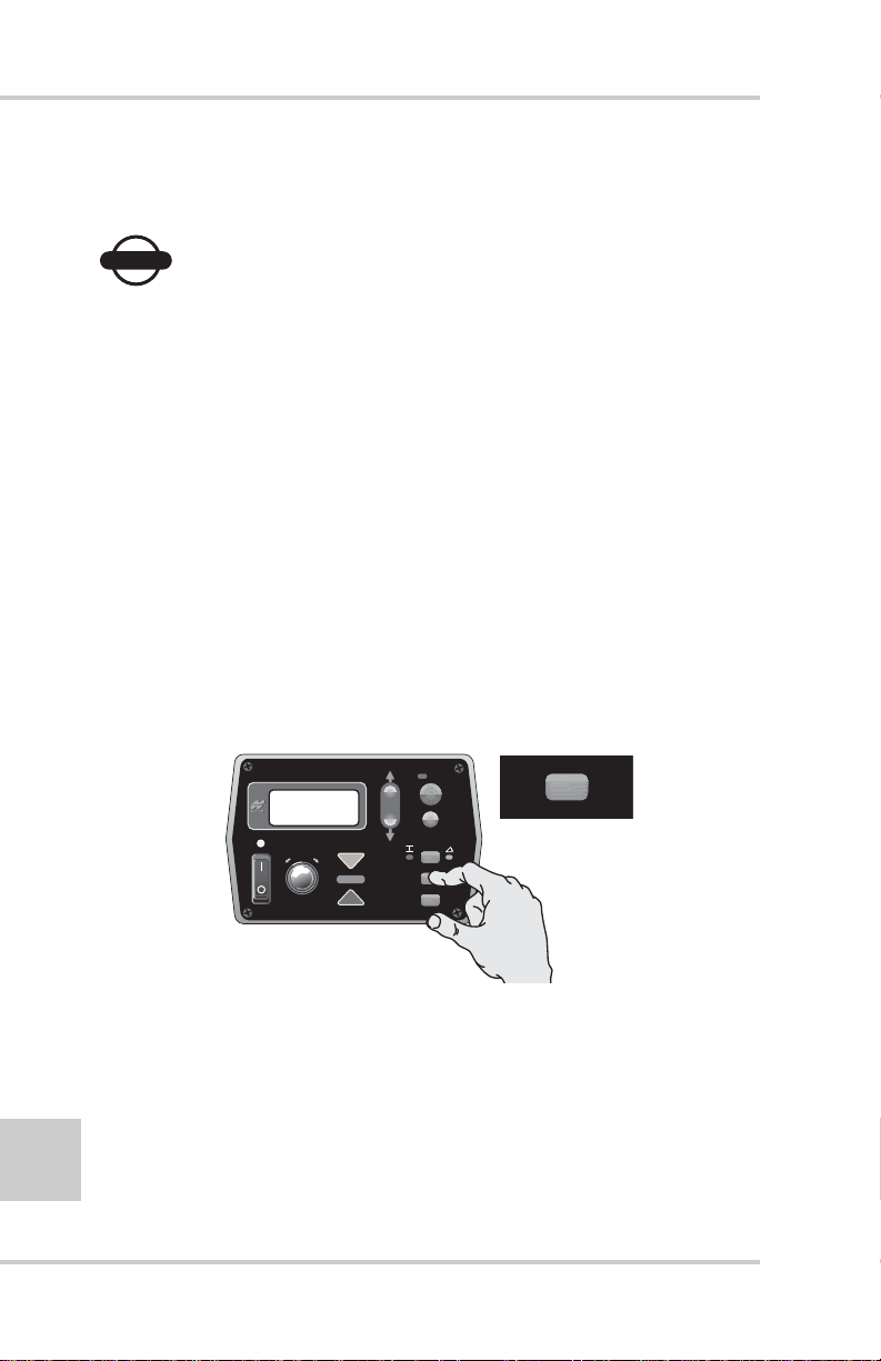
Cross Communication Button
If enabled, the Cross Communication button (Figure 4-10)
allows you to remotely control a second Control Box.
AU
TO
SURVEY
4-8
FiveSystem
Figure 4-10. Cross Communication Button
SET
NU
)
(ME
During cross communication, the Control Box that initiates the
communication (primary) displays and controls the settings of
the second Control Box.
Topcon Paver System Five Operator’s Manual
Page 77

1. Press and hold the Cross Communication button
(Figure 4-11).
AU
TO
SURVEY
Control Box
FiveSystem
(MENU
SET
)
Figure 4-11. Initiate Cross Communication
• The left arrow illuminates, indicating cross
communication has started (Figure 4-12).
AU
TO
SURVEY
FiveSystem
(MENU
SET
)
Figure 4-12. Cross Communication Started
• The right arrow illuminates once cross communication
with the second Control Box has been established. The
display now shows the settings of the second box
(Figure 4-13 on page 4-10). The cross communication
arrows on the second Control Box flash during cross
communication.
4-9
P/N 7010-0341 www.topconpositioning.com
Page 78

Operation & Menu Settings
AU
TO
SURVEY
FiveSystem
SET
(MENU
)
Figure 4-13. Cross Communication Established – Second Control Box Settings
2. Hold the cross communication button and view or make
changes to the settings in the second box (Figure 4-14).
AU
TO
SURVEY
FiveSystem
SET
(MENU
)
Figure 4-14. Remotely Change Second Control Box Settings
3. When finished, or to apply new settings to the second box,
release the cross communication button.
4-10
Topcon Paver System Five Operator’s Manual
Page 79

Control Box
Slope/Elevation Button
The elevation/slope button (Figure 4-15) is used to set the
System Five™ for slope or elevation control
AU
TO
E
l
evation
M
od
SURVEY
e
S
lop
M
od
e
e
FiveSystem
SET
(ME
NU
)
Figure 4-15. Slope/Elevation Button
Slope Mode
If the Control Box is connected to a slope sensor, the
desired cross slope can be dialed in for automatic control.
1. Press the Slope/Elevation button: the yellow LED next
to the Cross Slope Symbol illuminates.
2. Turn the Adjustment Knob to get the desired slope.
Elevation Mode
Press the Slope/Elevation b utton: the green LED next to the
Elevation Symbol illuminates.
P/N 7010-0341 www.topconpositioning.com
4-11
Page 80

Operation & Menu Settings
Survey/Indicate Button
Use the survey/indicate (Figure 4-16) button to lock on-grade
or continuously monitor the grade or slope setting on the LCD.
AU
TO
SURVEY
SURVEY
FiveSystem
Figure 4-16. Survey/Indicate Button
SET
NU
)
(ME
Using the Survey Function
Survey sets the sensor to on-grade.
Hold the Survey/Indicate button for one second until the
Control Box beeps and the on-grade light illuminates.
Using the Indicate Function
The grade or slope setting continuously displays on the
LCD during indicate mode.
NOTICE
NOTICE
Indicate puts the System Five in Manual Mode.
Press and hold the Survey/Indicate button for three
seconds, until the Control Box emits a second beep.
“IND” briefly displays on the LCD, then the grade or slope
setting. The Grade Adjustment LEDs remain dark.
To exit Indicate Mode, push either the Survey/Indicate
button or the Auto button.
4-12
Topcon Paver System Five Operator’s Manual
Page 81

Control Box
Auto/Manual Button
The auto/manual button (Figure 4-17) has three functions:
• In Automatic Mode, the tow point cylinders are
automatically adjusted as needed.
• In Manual Mode, displays grade corrections without
adjusting the tow point cylinders.
• Makes selections in the Performance Menu.
AUTO
AU
TO
SURVEY
FiveSystem
Figure 4-17. Auto/Manual Button
SET
NU
)
(ME
Using Automatic Mode
In automatic mode, the tow point cylinders are
automatically adjusted up or down to maintain proper
grade.
To enter auto mode, press the red button. The red LED
lights up showing that the Control Box is in auto mode.
Using Manual Mode
In manual mode, the LED displays grade corrections
without adjusting the tow point cylinders. In this mode, the
operator manually adjusts the tow point cylinders to reach
on-grade.
To enter manual mode, press in the red button. The red
LED will goes dark (unlit), showing that the Control Box is
in manual mode.
4-13
P/N 7010-0341 www.topconpositioning.com
Page 82

Operation & Menu Settings
r
Making Selections in the Performance Menu
When using the Performance Menu, the Auto/Manual
button selects settings and functions for the System Five
Control Box. See “Performance Menu Settings” on page 416 for information on the different menus available.
Jog Button
The jog button (Figure 4-18) manually moves the tow point up
or down, and is always active when the Control Box is turned
on.
• To raise the tow arm cylinder, push switch up.
• To lower the tow arm cylinder, push switch down.
P
r
ess t
o rai
AU
liner
TO
se
.
the cy
4-14
SURVEY
FiveSystem
SET
(ME
NU
)
Figure 4-18. Jog Button
P
r
ess t
the cy
o low
liner
.
Other Control Box Components
Other Control Box components include the following
(Figure 4-19 on page 4-15):
1. Mounting Knob – secures the Control Box to its mounting
bracket. The bracket has a jaw that matches up with the jaw
located on the side of the Box.
2. Serial Number Plate – contains Systems Five part and serial
numbers.
Topcon Paver System Five Operator’s Manual
e
Page 83

3. Audible Beeper – When the power is turned on, or
calibration selections are made, the beeper will sound. The
beeper may be turned Off or On for certain functions by
using the Beeper Alarm Mode (see the Accessing System
TM
Five
Performance Settings section).
1
2
n
P/N
S/N
Made in USA
ositas Blvd. Pleasanto
5758 W. Las P
CA 94588
3
Control Box
Figure 4-19. Other Control Box Components
P/N 7010-0341 www.topconpositioning.com
4-15
Page 84

Operation & Menu Settings
Performance Menu Settings
The System Five™ Control Box Performance Menu settings are a
series of features that allow System Five to be modif ied for operator
or performance enhancement. The Control Box automatically
stores all operating information when it is turned off.
If power is interrupted to the Control Box within two seconds after
making an adjustment, the new setting will not have had time to be
stored and the settings will revert to previous (or original) settings.
4-16
NOTICE
NOTICE
For some machine configurations, some menu
selections are inaccessible.
Table 4-2 lists the Control Box menus and their settings.
Table 4-2. Performance Menu Settings
Menu LED Symbol Range Factory Setting
Gain (Elevation) 1 – 200 25
Gain (Slope) 1 – 200 25
Valve Offset 1 – 999 135
Averaging 1 – 100 50
Elevation
Deadband
Slope Deadband .025% – .75% 0.075%
+
-
1 – 30 mm 3 mm
+
-
Topcon Paver System Five Operator’s Manual
Page 85

Performance Menu Settings
Table 4-2. Performance Menu Settings (Continued)
Menu LED Symbol Range Factory Setting
Beeper on/off off
Unit in, ft, cm in
Te st open, short, pass no setting
Factory settings are preset values that will run most pavers. If your
machine does not perform properly within those preset values,
adjust the setting accordingly until you have satisfactory machine
performance.
Follow these steps to access the Performance Menu.
1. Turn power off. While holding down the Set/Menu button turn
the box back on (Figure 4-20). The Auto LED light and Grade
Adjustment Direction arrows will flash.
AU
TO
SURVEY
FiveSystem
Figure 4-20. Accessing the Performance Menu
P/N 7010-0341 www.topconpositioning.com
(MENU
SET
)
4-17
Page 86

Operation & Menu Settings
2. Rotate the Grade Adjustment Knob to scroll through the menu
selections located on the LCD (Figure 4-21).
AU
TO
SURVEY
4-18
FiveSystem
(MENU
SET
)
Figure 4-21. Scrolling through the Performance Menu
3. Press the Auto button to select a menu item (Figure 4-22).
AU
TO
SURVEY
FiveSystem
Figure 4-22. Selecting Performance Menu Items
SET
(MENU
)
Topcon Paver System Five Operator’s Manual
Page 87

Performance Menu Settings
4. Turn the Grade Adjustment Knob to view the options available
for the Menu selection (Figure 4-23).
AU
TO
SURVEY
FiveSystem
SET
(MENU
)
Figure 4-23. View Menu Options
5. Press the Auto button again to store value (Figure 4-24).
AU
TO
SURVEY
FiveSystem
(MENU
SET
)
Figure 4-24. Storing Menu Value
6. To access other Menu settings, turn the Grade Adjustment
Knob. To exit the Performance Menu, press the Set/Menu
button.
See the following sections for greater detail on each menu item.
P/N 7010-0341 www.topconpositioning.com
4-19
Page 88

Operation & Menu Settings
Gain (Elevation)
This setting determines the speed at which System Five allows
the tow point cylinders to adjust to a change in elevation. For
faster hydraulic response, increase the gain value. For slower
hydraulic response, decrease the gain value.
The objective is to set the gain so the screed reacts to the
change in grade quickly, but without “overshooting” the new
elevation.
• Gain Elevation Value Range: 1-200
• Factory Preset: 25
Before setting the Gain, make sure the machine's hydraulic
flow controls valves are adjusted for proper cylinder speed
according to the manufacturer's recommendations. Typical
cylinder speed is 15-20 seconds for full up or down cylinder
travel.
1. From the Performance Menu, press the Auto button to
select Gain (Elevation) (Figure 4-25).
4-20
AU
TO
SURVEY
FiveSystem
Figure 4-25. Selecting Gain Elevation
(MENU
SET
)
2. Turn the Grade Adjustment Knob to select the desired
value, typically 25 for most paving applications
(Figure 4-26 on page 4-21).
Topcon Paver System Five Operator’s Manual
Page 89

Performance Menu Settings
AU
TO
SURVEY
FiveSystem
Figure 4-26. Selecting Gain Menu Option
SET
(MENU
)
3. Press the Auto button again to store value.
4. Rotate the Grade Adjustment Knob to access another item
in the Performance Menu, or press the Set/Menu button to
exit.
Gain (Slope Control)
This setting determines the speed at which System Five allows
the tow point c ylinders to adjust to a change in slope. F or f aster
hydraulic response, increase the gain value. For slower
hydraulic response, decrease the gain value.
The objective is to set the gain so the screed reacts to the
change in grade quickly but without “overshooting” on-grade.
Slope gain should not be set at a higher value than the elevation
gain on the other side of the paver.
• Gain Elevation Value Range: 1-200
• Factory Preset: 25
Before setting the Gain, ensure the machine's hydraulic flow
control valves are adjusted for proper cylinder speed according
to the manufacturer's recommendations. T ypical c ylinder speed
is 15-20 seconds for full up or down cylinder travel.
P/N 7010-0341 www.topconpositioning.com
4-21
Page 90

Operation & Menu Settings
1. From the Performance menu, press the Auto button to
select Gain (Slope Control) (Figure 4-27).
AU
TO
+
-
SURVEY
FiveSystem
SET
(MENU
)
Figure 4-27. Select Gain (Slope Control)
2. Turn the Grade Adjustment Knob to select the desired
value, typically 20% to 25% (Figure 4-28).
AU
TO
SURVEY
FiveSystem
(MENU
SET
)
Figure 4-28. Selecting the Gain Value
3. Press the Auto button again to store value.
4. Rotate the Grade Adjustment Knob to access another item
in the Performance Menu, or press the Set/Menu button to
exit.
4-22
Topcon Paver System Five Operator’s Manual
Page 91

Performance Menu Settings
NOTICE
NOTICE
Do not set slope gain at a higher value than the
elevation gain on the other side of the paver. A
higher value may cause the slope to be over
reactive.
Valve Offset
The valve offset is the minimum amount of electrical signals
sent to the valve which causes the hydraulic cylinder to move.
If the valve offset is too small, the sensor will not reach ongrade. Likewise, if the v alv e of fset v alue is too lar ge, the sensor
will move too much and overshoot On-Grade.
NOTICE
NOTICE
Valve offsets should be the first performance
menu function completed.
Valve offsets should be set before adjusting elevation and slope
gains, and averaging. The paver should be run until the
hydraulic oil is at normal operating temperature before the
value offset function is preformed. Once they are set, valve
offsets should not need to be adjusted unless the Control Box
has been moved to a new paver, or the hydraulic performance
has changed.
• Valve Offset value range – 1 to 999
• Factory preset – 135
Table 4-3 lists suggested valve offsets for different valve types.
Table 4-3. Suggested Valve Offsets
Valve Offset
Solenoid 135
Proportional 350
P/N 7010-0341 www.topconpositioning.com
4-23
Page 92

Operation & Menu Settings
1. From the Performance Menu, press the Auto button to
select Va lve Offset. This will automatically activate the
value screen for Raise Offsets. The raise grade correction
display arrow illuminates, and the Control Box will begin
sending a raise correction signal to the valve (Figure 4-29).
AU
TO
SURVEY
4-24
FiveSystem
SET
(MENU
)
Figure 4-29. Select Valve Offset
2. Turn the Grade Adjustment Knob counter clockwise,
decreasing the valve offset value until the hydraulic
cylinder no longer moves. Then slowly rotate the Grade
Adjustment Knob clockwise until the hydraulic cylinder
just begins to move up (Figure 4 -30).
AU
TO
SURVEY
FiveSystem
(MENU
SET
)
Figure 4-30. Setting the Raise Valve Offset Value
3. Press the Auto button to store the Raise Offset Value
(Figure 4-31 on page 4-25).
Topcon Paver System Five Operator’s Manual
Page 93

Performance Menu Settings
Pressing the Auto button also switches the box to Lower
Offset. The Lower Grade Correction Display arrow will
illuminate and the Control Box will begin sending a lower
correction signal to the value (Figure 4-31).
AU
TO
SURVEY
FiveSystem
SET
(MENU
)
Figure 4-31. Storing the Raise Offset Value
4. Turn the Grade Adjustment Knob counter-clockwise,
decreasing the valve offset value until the hydraulic
cylinder no longer moves. Then slowly rotate the Grade
Adjustment Knob clockwise until the hydraulic cylinder
just begins to move down (Figure 4-32).
AU
TO
SURVEY
FiveSystem
SET
(MENU
)
Figure 4-32. Setting the Lower Valve Offset Value
5. Press the Auto button to store the lower valve offset value
and return to the Performance Menu.
6. Rotate the Grade Adjustment Knob to access another item
in the Performance Menu, or press the Set/Menu button to
exit.
4-25
P/N 7010-0341 www.topconpositioning.com
Page 94

Operation & Menu Settings
Averaging
This setting changes the amount of dampening, or filtering,
applied to sonic tracker and laser receiver measurements. It can
be thought of as the time period over which a running average
of the elevation measurement is calculated. A lower value will
average fewer elevation measurements, allowing the system to
react more quickly to smaller grade changes. This will make it
more susceptible to fluctuations in temperature or small
obstructions.
A larger value will average more elevation measurements,
preventing the system from reacting to undesirable items close
to the reference. This will also make it less susceptible to
fluctuations in temperature or small obstructions.
• Averaging value range – 1 to 100
• Factory preset – 50
1. From the Performance Menu, press the Auto button to
select Averaging (Figure 4-33).
4-26
AU
TO
SURVEY
FiveSystem
Figure 4-33. Select Averaging
Topcon Paver System Five Operator’s Manual
SET
(MENU
)
Page 95

Performance Menu Settings
2. Turn the Grade Adjustment Knob to select the desired
value (Figure 4-34).
AU
TO
SURVEY
FiveSystem
Figure 4-34. Select Value
SET
(MENU
)
3. Press the Auto button again to store the value.
4. Rotate the Grade Adjustment Knob to access another item
in the Performance Menu, or press the Set/Menu button to
exit.
Deadband Elevation
Deadband is the area of the Working Window that is on-grade.
While the reference is within that area, the paver’s valves are
idle (closed). Therefore the wider the Deadband (on-grade
area), the more a reference can move up or down without a
correction being initiated. Once the signal from the reference is
out of the deadband, System Five will drive the hydraulics to
place the reference back in the CENTER of the deadband.
• Deadband Elevation value range – 1 to 30mm
• Factory preset – 3mm (01’ or 1/8”)
NOTICE
NOTICE
Select the amount of Deadband carefully
selected. Too small of a Deadband will cause the
tow point cylinder to constantly hunt up and
P/N 7010-0341 www.topconpositioning.com
4-27
Page 96

Operation & Menu Settings
down while the sensor tries to find On-Grade.
Too large of a deadband will not allow the sensor
to send grade corrections to the valves, causing
unwanted variations in the mat thickness.
1. From the Performance Menu, press the Auto button to
select Elevation Deadband (Figure 4-35).
AU
TO
SURVEY
4-28
FiveSystem
SET
(MENU
)
Figure 4-35. Select Elevation Deadband
2. Turn the Grade Adjustment Knob to select the desired
value, typically 3mm (0.01') (Figure 4-36).
AU
TO
SURVEY
FiveSystem
(MENU
SET
)
Figure 4-36. Select Value
3. Press the Auto button again to store the value.
4. Rotate the Grade Adjustment Knob to access another item
in the Performance Menu or press the Set/Menu button to
exit.
Topcon Paver System Five Operator’s Manual
Page 97

Performance Menu Settings
Deadband Slope
Deadband is the area of the Working Window that is on-grade.
While the reference is within that area, the paver’s valves are
idle (closed). Therefore the wider the Deadband (on-grade
area), the more a reference can move up or down without a
correction being initiated. Once the signal from the reference is
out of the deadband, System Five™ will dri v e the hydraulics to
place the reference back in the CENTER of the deadband.
When the Deadband is changed, it adds or takes away from the
fine correction region (1% above or below on-grade) of the
slope sensor; it does not add this distance to the overall working
range.
• Deadband Slope value range – 025 to 750%
• Factory preset – 075%
NOTICE
NOTICE
Select the amount of Deadband carefully. Too
small of a Deadband will cause the tow point
cylinder to constantly hunt up and down while
the sensor tries to find on-grade. Too large of a
deadband will not allow the sensor to send
grade corrections to the values, causing
unwanted variations in the mat thickness.
P/N 7010-0341 www.topconpositioning.com
4-29
Page 98

Operation & Menu Settings
1. From the Performance Menu, press the Auto button to
select Slope Deadband (Figure 4-37).
AU
TO
+
-
SURVEY
FiveSystem
SET
(MENU
)
Figure 4-37. Selecting Slope Deadband
2. Turn the Grade Adjustment Knob to select the desired
value, typically 075 (Figure 4-38).
AU
TO
%
FiveSystem
(MENU
SURVEY
SET
)
Figure 4-38. Select Value
3. Press the Auto button again to store the value.
4. Rotate the Grade Adjustment Knob to access another item
in the Performance Menu, or press the Set/Menu button to
exit.
4-30
Topcon Paver System Five Operator’s Manual
Page 99

Performance Menu Settings
Beeper Alarm
When in Automatic Mode and the Sonic Tracker receives a
reference signal outside of the Working Window (more than
2.0" from grade), a single audible beep will be heard.
1. From the Performance Menu, press the Auto button to
select Beeper (Figure 4-39).
AU
TO
SURVEY
FiveSystem
(MENU
SET
)
Figure 4-39. Select Beeper
2. Turn the Grade Adjustment Knob to turn the beeper ON or
OFF (Figure 4-40).
AU
TO
SURVEY
FiveSystem
SET
(MENU
)
Figure 4-40. Turning Beeper On
3. Press the Auto button again to store the choice.
4. Rotate the Grade Adjustment Knob to access another item
in the Performance Menu, or press the Set/Menu button to
exit.
4-31
P/N 7010-0341 www.topconpositioning.com
Page 100

Operation & Menu Settings
Unit
The Unit menu item sets the display to read in feet, inches, or
centimeters.
NOTICE
NOTICE
If the Unit value is changed, the working window
of the Sonic Tracker will have to be reset to
grade.
1. From the Performance Menu, press the Auto button to
select Units (Figure 4-41).
AU
TO
SURVEY
FiveSystem
Figure 4-41. Select Units
2. Rotate the Grade Adjustment Knob to select a unit for
measuring (feet, inches, or centimeters) (Figure 4-42 on
page 4-33).
SET
(MENU
)
4-32
Topcon Paver System Five Operator’s Manual
 Loading...