

Page 1

SURVEYING INSTRUMENTS
INSTRUCTION MANUAL
Onboard Station
OS series
OS-101
OS-102
OS-103
OS-105
OS-107
21406 99028
Page 2

HOW TO READ THIS MANUAL
Thank you for selecting the OS-101/102/103/105/107.
• Please read this instruction manual carefully, before using this product.
• OS has a function to output data to a connected host computer. Command operations from a host
computer can also be performed. For details, refer to "Communication manual" and ask your local
dealer.
• The specifications and general appearance of the instrument may be altered at any time and may
differ from those appearing in brochures and this manual.
• The content of this manual may be altered at any time.
• Some of the diagrams shown in this manual may be simplified for easier understanding.
Symbols
The following conventions are used in this manual.
Indicates precautions and important items which should be read before
:
operations.
[Softkey] etc. : Indicates softkeys on the display and window dialog buttons.
{Key} etc. : Indicates keys on the operation panel.
<Screen title> etc.: Indicates screen titles.
: Indicates the chapter title to refer to for additional information.
: Indicates supplementary explanation.
: Indicates an explanation for a particular term or operation.
i
Page 3

HOW TO READ THIS MANUAL
Low temperature
seal
Li-ion
S Li-ion
Notes regarding manual style
• Except where stated, “OS” means OS-101/102/103/105/107 in this manual.
• The OS Series is available in "standard", and "Low Temperature" models. Users with a "Low
Temperature Model" should read the additional precautions specific to use under low temperatures.
● Low Temperature Model
Low Temperature Models display the seal shown at right.
• Do not remove the Low Temperature Model seal from the
instrument. This seal is used for model recognition by our
engineers during maintenance.
• Screens and illustrations appearing in this manual are of OS-103 (with Bluetooth module and
display on face 1 only). Face 2 display is available as standard or as a factory option depending on
the country of purchase.
• Location of softkeys in screens used in procedures is based on the factory setting. It is possible to
change the allocation of softkeys.
Softkey allocation: "20.6 Allocating Key Functions"
• Learn basic operations in "4. PRODUCT OUTLINE" and "5. BASIC OPERATION" before you read
each measurement procedure. For selecting options and inputting figures, see "5.1 Basic Key
Operation".
• Measurement procedures are based on continuous measurement. Some information about
procedures when other measurement options are selected can be found in “Note” (
).
• KODAK is a registered trademark of Eastman Kodak Company.
• Bluetooth® is a registered trademark of Bluetooth SIG, Inc.
• Windows and Windows CE are registered trademarks of Microsoft Corporation.
• All other company and product names featured in this manual are trademarks or registered
trademarks of each respective organization.
This is the mark of the Japan Surveying
Instruments Manufacturers Association.
ii
Page 4

CONTENTS
1. PRECAUTIONS FOR SAFE OPERATION ......................... 1
2. PRECAUTIONS .................................................................. 4
3. LASER SAFETY INFORMATION ....................................... 8
4. PRODUCT OUTLINE........................................................ 10
4.1 Parts of the Instrument .............................................................. 10
4.2 Mode Structure .......................................................................... 14
4.3 Bluetooth Wireless Technology ................................................. 15
5. BASIC OPERATION ......................................................... 17
5.1 Basic Key Operation .................................................................. 17
5.2 Display Functions ...................................................................... 21
5.3 Starkey Mode ............................................................................ 25
5.4 Inputting Characters using the Input Panel ............................... 25
6. INSERTING USB MEMORY............................................. 30
7. USING THE BATTERY ..................................................... 31
7.1 Battery Charging ....................................................................... 31
7.2 Installing/Removing the Battery ................................................. 32
8. SETTING UP THE INSTRUMENT.................................... 34
8.1 Centering ................................................................................... 34
8.2 Levelling .................................................................................... 36
9. POWER ON/OFF .............................................................. 38
9.1 Resolving Software Issues ........................................................ 39
9.2 Configuring the Touch Panel ..................................................... 39
10. CONNECTING TO EXTERNAL DEVICES ....................... 41
10.1 Wireless Communication using Bluetooth Technology ............. 41
10.2 Communication between the OS and Companion Device ........ 46
10.3 Connecting to USB devices ....................................................... 48
10.4 Connection via RS232C cable .................................................. 51
11. FOCUSSING AND TARGET SIGHTING .......................... 52
12. ANGLE MEASUREMENT................................................. 53
12.1 Measuring the Horizontal Angle between Two Points
(Horizontal Angle 0°) ................................................................. 53
12.2 Setting the Horizontal Angle to a Required Value
(Horizontal Angle Hold) ............................................................. 54
12.3 Angle measurement and Outputting the Data ........................... 55
iii
Page 5

13. DISTANCE MEASUREMENT........................................... 56
13.1 Returned Signal Checking ........................................................ 56
13.2 Distance and Angle Measurement ............................................ 58
13.3 Distance Measurement and Outputting the Data ...................... 59
13.4 REM Measurement ................................................................... 60
14. COORDINATE MEASUREMENT..................................... 62
14.1 Entering Instrument Station Data .............................................. 62
14.2 Azimuth Angle Setting ............................................................... 63
14.3 3-D Coordinate Measurement ................................................... 66
15. RESECTION MEASUREMENT........................................ 68
15.1 Coordinate Resection Measurement ......................................... 69
15.2 Height Resection Measurement ................................................ 73
16. SETTING-OUT MEASUREMENT .................................... 78
16.1 Using the Guide Light ................................................................ 78
16.2 Distance Setting-out Measurement ........................................... 79
16.3 Coordinates Setting-out Measurement ..................................... 84
16.4 REM Setting-out Measurement ................................................. 87
17. OFFSET MEASUREMENT............................................... 90
17.1 Single-distance Offset Measurement ........................................ 90
17.2 Angle Offset Measurement ....................................................... 92
17.3 Two-distance Offset Measurement ........................................... 94
18. MISSING LINE MEASUREMENT..................................... 97
18.1 Measuring the Distance between 2 or more Points .................. 97
18.2 Changing the Starting Point ...................................................... 99
19. SURFACE AREA CALCULATION.................................. 101
20. CHANGING THE SETTINGS ......................................... 105
20.1 Observation Conditions ........................................................... 105
20.2 Instrument Configuration ......................................................... 108
20.3 EDM Settings .......................................................................... 110
20.4 Allocating User-defined Tabs .................................................. 114
20.5 Customizing Screen Controls .................................................. 116
20.6 Allocating Key Functions ......................................................... 118
20.7 Changing Starkey Mode Icons ................................................ 121
20.8 Units ........................................................................................ 123
20.9 Changing Password ................................................................ 124
20.10 Date and Time ......................................................................... 125
iv
Page 6

20.11 Restoring Default Settings ....................................................... 125
21. WARNING AND ERROR MESSAGES........................... 126
22. CHECKS AND ADJUSTMENTS..................................... 129
22.1 Circular Level .......................................................................... 129
22.2 Tilt Sensor ............................................................................... 130
22.3 Collimation ............................................................................... 133
22.4 Reticle ..................................................................................... 134
22.5 Optical Plummet ...................................................................... 136
22.6 Additive Distance Constant ..................................................... 137
22.7 Laser Plummet (Option) .......................................................... 139
23. POWER SUPPLY SYSTEM ........................................... 142
24. PRISM SYSTEM............................................................. 143
25. OPTIONAL ACCESSORIES........................................... 144
26. SPECIFICATIONS .......................................................... 146
27. EXPLANATIONS ............................................................ 151
27.1 Manually Indexing the Vertical Circle by Face 1/2 Measurement .. 151
27.2 Correction for Refraction and Earth Curvature ........................ 152
28. REGULATIONS .............................................................. 153
29. INDEX ............................................................................. 158
v
Page 7

1. PRECAUTIONS FOR SAFE OPERATION
For the safe use of the product and prevention of injury to operators and other persons as well as
prevention of property damage, items which should be observed are indicated by an exclamation point
within a triangle used with WARNING and CAUTION statements in this operator’s manual.
The definitions of the indications are listed below. Be sure you understand them before reading the
manual’s main text.
Definition of Indication
General
WARNING
CAUTION
This symbol indicates items for which caution (hazard warnings inclusive) is urged.
Specific details are printed in or near the symbol.
This symbol indicates items which are prohibited. Specific details are printed in or near
the symbol.
This symbol indicates items which must always be performed. Specific details are printed
in or near the symbol.
Warning
Do not use the unit in areas exposed to high amounts of dust or ash, in areas where there
is inadequate ventilation, or near combustible materials. An explosion could occur.
Do not perform disassembly or rebuilding. Fire, electric shock, burns, or hazardous
radiation exposure could result.
Never look at the sun through the telescope. Loss of eyesight could result.
Do not look at reflected sunlight from a prism or other reflecting object through the
telescope. Loss of eyesight could result.
Direct viewing of the sun using the telescope during sun observation will cause loss of
eyesight. Use a solar filter (option) for sun observation.
When securing the instrument in the carrying case make sure that all catches, including
the side catches, are closed. Failure to do so could result in the instrument falling out
while being carried, causing injury.
Ignoring this indication and making an operation error could possibly
result in death or serious injury to the operator.
Ignoring this indication and making an operation error could possibly
result in personal injury or property damage.
Caution
Do not use the carrying case as a footstool. The case is slippery and unstable so a
person could slip and fall off it.
1
Page 8

Do not place the instrument in a case with a damaged catch, belt or handle. The case or
instrument could be dropped and cause injury.
Do not wield or throw the plumb bob. A person could be injured if struck.
Secure handle to main unit with handle locks. Failure to properly secure the handle could
result in the unit falling off while being carried, causing injury.
Tighten the adjustment tribrach clamp securely. Failure to properly secure the clamp
could result in the tribrach falling off while being carried, causing injury.
Power Supply
Warning
Do not short circuit. Heat or ignition could result.
Do not place articles such as clothing on the battery charger while charging batteries.
Sparks could be induced, leading to fire.
Do not use voltage other than the specified power supply voltage. Fire or electrical shock
could result.
Do not use batteries other than those designated. An explosion could occur, or abnormal
heat generated, leading to fire.
Do not use damaged power cords, plugs or loose outlets. Fire or electric shock could
result.
1. PRECAUTIONS FOR SAFE OPERATION
Do not use power cords other than those designated. Fire could result.
Use only the specified battery charger to recharge batteries. Other chargers may be of
different voltage rating or polarity, causing sparking which could lead to fire or burns.
Do not use the battery, charger or AC (power) cable for any other equipment or purpose.
Fire or burns caused by ignition could result.
Do not heat or throw batteries into fire. An explosion could occur, resulting in injury.
To prevent shorting of the battery in storage, apply insulating tape or equivalent to the
terminals. Otherwise shorting could occur resulting in fire or burns.
Do not use batteries or the battery charger if wet. Resultant shorting could lead to fire or
burns.
Do not connect or disconnect power supply plugs with wet hands. Electric shock could
result.
Caution
Do not touch liquid leaking from batteries. Harmful chemicals could cause burns or
blisters.
2
Page 9

Tripod
Caution
When mounting the instrument to the tripod, tighten the centering screw securely. Failure
to tighten the screw properly could result in the instrument falling off the tripod, causing
injury.
Tighten securely the leg fixing screws of the tripod on which the instrument is mounted.
Failure to tighten the screws could result in the tripod collapsing, causing injury.
Do not carry the tripod with the tripod shoes pointed at other persons. A person could be
injured if struck by the tripod shoes.
Keep hands and feet away from the tripod shoes when fixing the tripod in the ground. A
hand or foot stab wound could result.
Tighten the leg fixing screws securely before carrying the tripod. Failure to tighten the
screws could lead to the tripod legs extending, causing injury.
Bluetooth wireless technology
Warning
Do not use within the vicinity of hospitals. Malfunction of medical equipment could
result.
Use the instrument at a distance of at least 22 cm from anyone with a cardiac
pacemaker. Otherwise, the pacemaker may be adversely affected by the
electromagnetic waves produced and cease to operate as normal.
Do not use onboard aircraft. The aircraft instrumentation may malfunction as a result.
Do not use within the vicinity of automatic doors, fire alarms and other devices with
automatic controls as the electromagnetic waves produced may adversely affect
operation resulting in an accident.
1. PRECAUTIONS FOR SAFE OPERATION
Use under low temperatures (Low Temperature Model only)
Caution
In temperatures around -30°C do not touch metal parts on the main unit, the
accessories and the carrying case with bare hands. Exposed skin may stick to parts
and cause burns and loss of skin.
3
Page 10
2. PRECAUTIONS
Charging Battery
• Be sure to charge the battery within the charging temperature range.
Charging temperature range: 0 to 40°C
Warranty policy for Battery
• Battery is an expendable item. The decline in retained capacity depending on the repeated charging/
discharging cycle is out of warranty.
Bluetooth Wireless Technology
• Bluetooth function may not be built in depending on telecommunications regulations of the country
or the area where the instrument is purchased. Contact your local dealer for the details.
Telescope
• Aiming the telescope at the sun will cause internal damage to the instrument. Use the solar filter
when observing the sun.
"25. Optional accessories"
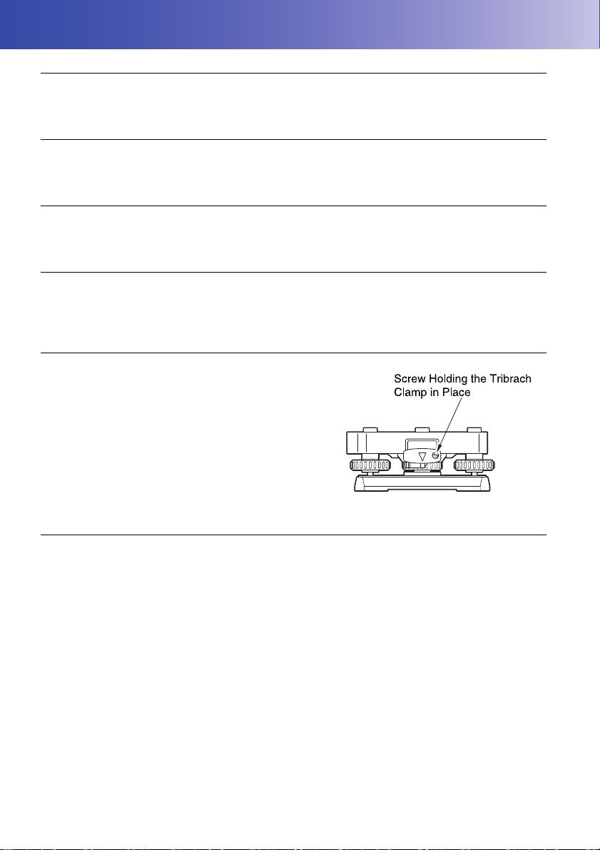
Tribrach Clamp and Handle
• When the instrument is shipped, the tribrach clamp is held
firmly in place with a locking screw to prevent the
instrument from shifting on the tribrach. Before using the
instrument the first time, loosen this screw with a
screwdriver. And before transporting it, tighten the locking
screw to fasten the tribrach clamp in place so that it will not
shift on the tribrach.
• The OS handle can be removed. When operating the OS
with the handle attached, always make sure that the handle
is securely fixed to the OS body with the handle locks.
Precautions concerning water and dust resistance
OS conforms to IP65 specifications for waterproofing and dust resistance when battery cover,
connector cap and the external interface hatch and are closed.
• Be sure to correctly attach the connector caps to protect the OS from moisture and dust particles
when the connector is not in use.
• Make sure that moisture or dust particles do not come in contact with the terminal or connectors.
Operating the instrument with moisture or dust on the terminal or connectors may cause damage to
the instrument.
• Make sure that the inside of the carrying case and the instrument are dry before closing the case. If
moisture is trapped inside the case, it may cause the instrument to rust.
• If there is a crack or deformation in the rubber packing for the battery cover or external interface
hatch, stop using and replace the packing.
• To retain the waterproof property, it is recommended that you replace the rubber packing once every
two years. To replace the packing, contact your local dealer.
4
Page 11

2. PRECAUTIONS
Speaker
• Do not press the speaker / luminance sensor / microphone hole using
something with a pointed tip. Doing so will damage an internal waterproof
sheet, resulting in a degraded waterproof property.
The Lithium Battery
• The lithium battery is used to maintain the OS Calendar & Clock function. It can back up data for
approximately 5 years of normal use and storage (Temperature = 20°, humidity = about 50%), but
its lifetime may be shorter depending on circumstances.
Vertical and horizontal clamps
• Always fully release the vertical/horizontal clamps when rotating the instrument or telescope.
Rotating with clamp(s) partially applied may adversely affect accuracy.
Backing up data
• Data should be backed up (transferred to an external device etc.) on a regular basis to prevent data
loss.
Use under low temperatures (Low Temperature Model only)
• Do not use force to scrape off frost from the lens or display unit screen. Frost is an abrasive material
and may scratch the instrument.
• If ice or snow attaches itself to the unit, wipe it off with a soft cloth, or place the unit in a warm room
until the ice melts, and then wipe off the meltwater. Operating the unit with ice or snow attached may
cause operation errors to occur.
• Wipe off condensation with a soft cloth before using the instrument. Not doing so may cause
operation errors to occur.
• The working duration of battery BDC70 will rapidly decline in cold temperatures. When using the
instrument in temperatures around -30°C, we recommend that you use an external battery (optional
accessory). However, if you unavoidably must use battery BDC70 for measurements in
temperatures around -30°C, recharge the battery in a warm room and keep the battery in a warm
place such as your pocket until it is used. (Working duration of battery will change with
environmental conditions.)
• The lens cap and lens hood may become difficult to attach in low temperatures. Keep them in a
warm place such as a pocket until attached.
• If the unit is carried between locations that have extreme temperature differences, protect the unit
from rapid temperature change by placing it in the carrying case.
• Please use the tribrach supplied as standard. If a different tribrach is used, angle measurement
errors may occur.
5
Page 12

2. PRECAUTIONS
Other precautions
• Never place the instrument directly on the ground. Sand or dust may cause damage to the screw
holes or the centering screw on the base plate.
• Do not perform vertical rotation of the telescope when using the lens hood, diagonal eyepiece, or
solar filter. Such accessories may strike the OS causing damage.
• Protect the instrument from heavy shocks or vibration.
• Protect the instrument from rain or drizzle with an umbrella or waterproof cover.
• Never carry the instrument on the tripod to another site.
• Turn the power off before removing the battery.
• Remove the battery before placing the OS in its case.
• Make sure that the instrument and the protective lining of the carrying case are dry before closing the
case. The case is hermetically sealed and if moisture is trapped inside, the instrument could rust.
• Consult your local dealer before using the instrument under special conditions such as long periods
of continuous use or high levels of humidity. In general, special conditions are treated as being
outside the scope of the product warranty.
Exporting this product (Relating EAR)
• This product is equipped with the parts/units, and contains software/technology, which are subject
to the EAR (Export Administration Regulations). Depending on countries you wish to export or bring
the product to, a US export license may be required. In such a case, it is your responsibility to obtain
the license. The countries requiring the license as of May 2013 are shown below. Please consult the
Export Administration Regulations as they are subject to change.
North Korea
Iran
Syria
Sudan
Cuba
URL for the EAR of the US: http://www.bis.doc.gov/policiesandregulations/ear/index.htm
Exporting this product (Relating telecommunications regulations)
• Wireless communication module is incorporated in the instrument. Use of this technology must be
compliant with telecommunications regulations of the country where the instrument is being used.
Even exporting the wireless communication module may require conformity with the regulations.
Contact your local dealer in advance.
Maintenance
• Wipe off moisture completely if the instrument gets wet during survey work.
• Always clean the instrument before returning it to the case. The lens requires special care. First,
dust it off with the lens brush to remove tiny particles. Then, after providing a little condensation by
breathing on the lens, wipe it with the wiping cloth.
• If the display is dirty, carefully wipe it with a soft, dry cloth. To clean other parts of the instrument or
the carrying case, lightly moisten a soft cloth in a mild detergent solution. Wring out excess water
until the cloth is slightly damp, then carefully wipe the surface of the unit. Do not use any alkaline
cleaning solutions, alcohol, or any other organic solvents on the instrument or display.
For temporal de-activating the touch panel, see "5.2 Display Functions", "20. CHANGING
THE SETTINGS"
6
Page 13

2. PRECAUTIONS
• Store the instrument in a dry room where the temperature remains fairly constant.
• Check the tripod for loose fit and loose screws.
• If any trouble is found on the rotatable portion, screws or optical parts (e.g. lens), contact your local
dealer.
• When the instrument is not used for a long time, check it at least once every 3 months.
"22. CHECKS AND ADJUSTMENTS"
• When removing the instrument from the carrying case, never pull it out by force. The empty carrying
case should be closed to protect it from moisture.
• Check the instrument for proper adjustment periodically to maintain the instrument accuracy.
Exceptions from responsibility
• The user of this product is expected to follow all operating instructions and make periodic checks
(hardware only) of the product’s performance.
• The manufacturer, or its representatives, assumes no responsibility for results of faulty or intentional
usage or misuse including any direct, indirect, consequential damage, or loss of profits.
• The manufacturer, or its representatives, assumes no responsibility for consequential damage, or
loss of profits due to any natural disaster, (earthquake, storms, floods etc.), fire, accident, or an act
of a third party and/or usage under unusual conditions.
• The manufacturer, or its representatives, assumes no responsibility for any damage (change of
data, loss of data, loss of profits, an interruption of business etc.) caused by use of the product or
an unusable product.
• The manufacturer, or its representatives, assumes no responsibility for any damage, and loss of
profits caused by usage different to that explained in the operator’s manual.
• The manufacturer, or its representatives, assumes no responsibility for damage caused by incorrect
operation, or action resulting from connecting to other products.
7
Page 14
3. LASER SAFETY INFORMATION
࣮ࣞࢨගࡢฟཱྀ
AVOID EXPOSURE-Laser radiation
is emitted from this aperture.
┠ࡢ┤᥋⿕ࡤࡃࢆ㑊ࡅࡿࡇ
ࢡࣛࢫ5࣮ࣞࢨ〇ရ
-,6&
LASER RADIATION
AVOID DIRECT EYE EXPOSURE
0$;P:/'QP
MAX 5mW LD 625-695nm
CLASS3R LASER PRODUCT
IEC 60825-1
࣮ࣞࢨග
Laster beam emitted
from here
(only when laser plummet
function is mounted)
Laster beam
emitted from
here
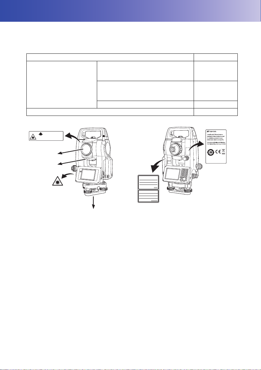
OS is classified as the following class of Laser Product according to IEC Standard Publication 608251 Ed.3.0: 2014 and United States Government Code of Federal Regulation FDA CDRH 21CFR Part
1040.10 and 1040.11 (Complies with FDA performance standards for laser products except for
deviations pursuant to Laser Notice No.50, dated June 24, 2007.)
Device Laser class
Light beam used for measurement
(When reflectorless measurement is
selected in Config mode)
EDM device in objective lens
Light beam used for measurement
(When prism or reflective sheet is
selected as target in Config mode)
Laser-pointer Class 3R
Laser plummet (option) Class 2
Class 3R
Class 1
• EDM device is classified as Class 3R Laser Product when reflectorless measurement is selected.
When target (reflector) is set to prism or reflective sheet, the output is equivalent to the safer class 1.
Warning
• Use of controls or adjustments or performance of procedures other than those specified herein may
result in hazardous radiation exposure.
• Follow the safety instructions on the labels attached to the instrument as well as in this manual to
ensure safe use of this laser product.
• Never intentionally point the laser beam at another person. The laser beam is injurious to the eyes
and skin. If an eye injury is caused by exposure to the laser beam, seek immediate medical attention
from a licensed ophthalmologist.
• Do not look directly into the laser beam source. Doing so could cause permanent eye damage.
• Do not stare at the laser beam. Doing so could cause permanent eye damage.
• Never look at the laser beam through a telescope, binoculars or other optical instruments. Doing so
could cause permanent eye damage.
• Sight targets so that the laser beam does not stray from them.
8
Page 15

3. LASER SAFETY INFORMATION
Caution
• Perform checks at start of work and periodic checks and adjustments with the laser beam emitted
under normal conditions.
• When the instrument is not being used, turn off the power and replace the lens cap.
• When disposing of the instrument, destroy the battery connector so that the laser beam cannot be
emitted.
• Operate the instrument with due caution to avoid injuries that may be caused by the laser beam
unintentionally striking a person in the eye. Avoid setting the instrument at heights at which the path
of the laser beam may strike pedestrians or drivers at head height.
• Never point the laser beam at mirrors, windows or surfaces that are highly reflective. The reflected
laser beam could cause serious injury.
• Only those who have been received training as per the following items shall use this product.
• Read the Operator’s manual for usage procedures for this product.
• Hazardous protection procedures (read this chapter).
• Requisite protective gear (read this chapter).
• Accident reporting procedures (stipulate procedures beforehand for transporting the injured and
contacting physicians in case there are laser induced injuries).
• Persons working within the range of the laser beam are advised to wear eye protection which
corresponds to the laser wavelength of the instrument being used
• Areas in which the laser is used should be posted with a standard laser warning sign.
• When using the laser-pointer function, be sure to turn OFF the output laser after distance
measurement is completed. Even if distance measurement is canceled, the laser-pointer function is
still operating and the laser beam continues to be emitted.
9
Page 16
4. PRODUCT OUTLINE
4
4
16
1
2
3
8
6
5
7A
9
10
11
13
12
15
14
17
18
4
4
19
22
20
21
23
24
26
25
27
28
29
15
7B
OS-101/102 and low temperature models only
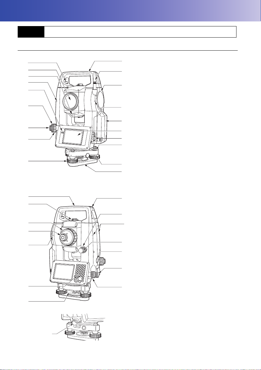
4.1 Parts of the Instrument
Parts and functions of the instrument
1 Handle
2 Bluetooth antenna
3 External interface hatch
(USB port / Reset button)
"10. CONNECTING TO EXTERNAL
DEVICES"
4 Instrument height mark
5 Battery cover
6 Display unit
7A Serial connector
7B Serial / External power source connector
8 Circular level
9 Circular level adjusting screws
10 Base plate
11 Levelling foot screw
12 Optical plummet focussing ring
13 Optical plummet eyepiece
14 Optical plummet reticle cover
15 Luminance sensor
16 Guide light
17 Objective lens
(Includes " Laser-pointer function")
18 Handle locking screw
19 Tubular compass slot
20 Vertical clamp
21 Vertical fine motion screw
22 Trigger key
23 Horizontal fine motion screw
24 Horizontal clamp
25 Tribrach clamp
26 Telescope eyepiece screw
27 Telescope focussing ring
28 Sighting collimator
29 Instrument center mark
10
Page 17
4. PRODUCT OUTLINE
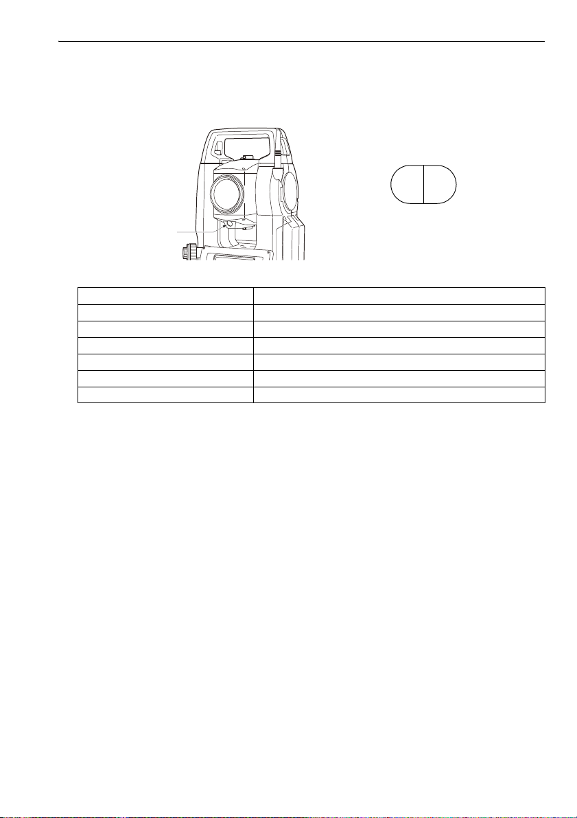
green
red
Guide light
(When seen from the objective lens side
while the instrument is in the Face 1 state)
Guide light
Setting-out measurement etc. can be carried out effectively using the guide light. The guide light
is composed of a light that is divided into green and red sections. A poleman can ascertain the
present position by checking the guide light color.
Indication for positioning target during setting-out measurement
Light status Meaning
Increased flashing speed (From position of poleman) Move target toward OS
Decreased flashing speed (From position of poleman) Move target away from OS
Fast flashing Target is at correct distance
Red (From position of poleman) Move target left
Green (From position of poleman) Move target right
Red and Green Target is at correct horizontal position
The guide light indicator is lit or flashes depending on the status of the guide light.
"16.1 Using the Guide Light"
Sighting collimator
Use sighting collimator to aim the OS in the direction of the measurement point.
Turn the instrument until the apex of the triangle in the sighting collimator is aligned with the
target. A circle surrounds the triangle to make it easier to locate.
Instrument height mark
The height of the OS is 236mm (from tribrach dish to this mark). "Instrument height" is input
when setting instrument station data and is the height from the measuring point (where OS is
mounted) to this mark.
Trigger key
When the Trigger key is pressed OS carries out the operation indicated by the softkey in bold
type on the screen. This allows the user to continue operation without having to return to the
display to press softkeys.
Laser-pointer function
A target can be sighted with a red laser beam in dark locations without the use of the telescope.
11
Page 18
4. PRODUCT OUTLINE
Handle
Handle
rocking screws
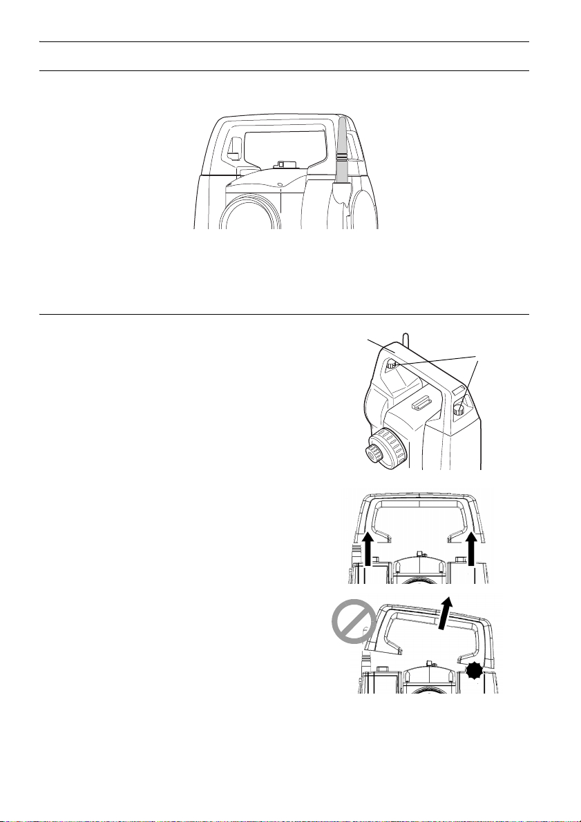
Bluetooth antenna (Models with Bluetooth module only)
The Bluetooth antenna allows communication via Bluetooth wireless technology.
• Handle the antenna with care. The antenna may be damaged if struck during operation or while
being stored in the carrying case.
Handle
The carrying handle can be removed from the
instrument. To remove it, loosen the handle
rocking screw.
• To remove the handle, hold both sides of the handle
and lift it straight above. If you hold the handle by
one hand or incline it, the contacts on the handle
may be damaged.
12
Page 19
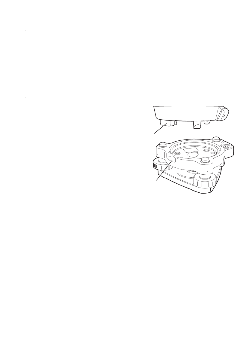
Detaching the instrument from the tribrach
(1)
(2)
1. Loosen the tribrach locking screw by turning 2
or 3 rotations in the counterclockwise
direction.
2. Turn the tribrach clamp counterclockwise to
loosen.
3. Lift the instrument to detach.
Attaching the instrument to the tribrach
1. Check that the tribrach locking screw has
been loosened.
2. Align (1) and (2) and lower the instrument onto
the tribrach.
3. Turn the tribrach clamp clockwise to tighten.
4. PRODUCT OUTLINE
13
Page 20
4. PRODUCT OUTLINE
●Program mode
●Starkey mode
Top menu
Observation mode (switching by tab)
Menu mode
Config mode
C“5.2 Display
Functions
٨”Graphic“ tab”
ÛVersionÝ
=OK?
]ڎ_
●Basic mode
C“5.4 Starkey mode”
]PRG_
]ڎ_
]ESC_
C“20.Changing the settings”
C“12. to 19”
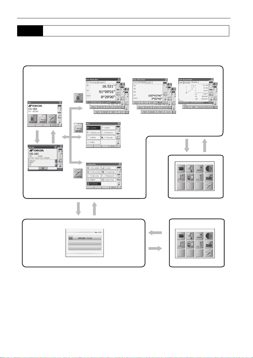
4.2 Mode Structure
The diagram below describes the different modes of the OS and key operations for navigating
between them.
• Switching between modes is not possible during distance measurement.
• Do not switch between modes by {PRG} or not turn OFF the power just after pressing {PRG}
(during displaying the message "Executing program mode").
14
Page 21

4. PRODUCT OUTLINE
4.3 Bluetooth Wireless Technology
• Bluetooth function may not be built in depending on telecommunications regulations of the country
or the area where the instrument is purchased. Contact your local dealer for the details.
• Use of this technology must be authorized according to telecommunications regulations of the
country where the instrument is being used. Contact your local dealer in advance.
"28. REGULATIONS"
• TOPCON CORPORATION is not liable for the content of any transmission nor any content related
thereto. When communicating important data, run tests beforehand to ascertain that communication
is operating normally.
• Do not divulge the content of any transmission to any third party.
Radio interference when using Bluetooth technology
Bluetooth communication with the OS uses the 2.4 GHz frequency band. This is the same band used
by the devices described below.
•Industrial, scientific, and medical (ISM) equipment such as microwaves and pacemakers.
• portable premises radio equipment (license required) used in factory production lines etc.
• portable specified low-power radio equipment (license-exempt)
•IEEE802.11b/IEEE802.11g standard wireless LAN devices
The above devices use the same frequency band as Bluetooth communications. As a result, using the
OS within proximity to the above devices may result in interference causing communication failure or
reduction of transmission speed.
Although a radio station license is not required for this instrument, bear in mind the following points
when using Bluetooth technology for communication.
Regarding portable premises radio equipment and portable specified low-power radio
equipment:
• Before starting transmission, check that operation will not take place within the vicinity of
portable premises radio equipment or specified low-power radio equipment.
• In the case that the instrument causes radio interference with portable premises radio
equipment, terminate the connection immediately and take measures to prevent further
interference (e.g. connect using an interface cable).
• In the case that the instrument causes radio interference with portable specified low-power radio
equipment, contact your local dealer.
When using the OS in proximity to IEEE802.11b or IEEE802.11g standard wireless LAN
devices, turn off all devices not being used.
• Interference may result, causing transmission speed to slow or even disrupting the connection
completely. Turn off all devices not being used.
Do not use the OS in proximity to microwaves.
• Microwave ovens can cause significant interference resulting in communication failure. Perform
communication at a distance of 3m or more from microwave ovens.
Refrain from using the OS in proximity to televisions and radios.
15
Page 22

4. PRODUCT OUTLINE
• Televisions and radios use a different frequency band to Bluetooth communications.
However, even if the OS is used within proximity to the above equipment with no adverse effects
with regard to Bluetooth communication, moving a Bluetooth compatible device (including the
OS) closer to said equipment may result in electronic noise in sound or images, adversely
affecting the performance of televisions and radios.
Precautions regarding transmission
For best results
• The usable range becomes shorter when obstacles block the line of sight, or devices such as
PDAs or computers are used. Wood, glass and plastic will not impede communication but the
usable range becomes shorter. Moreover, wood, glass and plastic containing metal frames,
plates, foil and other heat shielding elements as well as coatings containing metallic powders
may adversely affect Bluetooth communication and concrete, reinforced concrete, and metal will
render it impossible.
• Use a vinyl or plastic cover to protect the instrument from rain and moisture. Metallic materials
should not be used.
• The direction of the Bluetooth antenna can have adverse effects upon usable range.
Reduced range due to atmospheric conditions
• The radio waves used by the OS may be absorbed or scattered by rain, fog, and moisture from
the human body with the limit of usable range becoming lower as a result. Similarly, usable range
may also shorten when performing communication in wooded areas. Moreover, as wireless
devices lose signal strength when close to the ground, perform communication at as high a
position as possible.
• TOPCON CORPORATION cannot guarantee full compatibility with all Bluetooth products on the
market.
16
Page 23
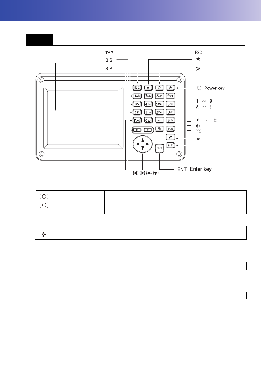
5. BASIC OPERATION
SHIFT
Display unit
Luminance sensor / Microphone
Target type
Program mode
Switching the page
Input mode
SHIFT
Illumination key
FUNC
{ }
{ }
{ }
{ }
{ }
{ }
{ }
{ }
{ }
{ }
{ }
{ }
{ }
{ }
{ }
{ }
{ }
{ }
{ }
{ }
Starkey mode
Learn basic key operations here before you read each measurement procedure.
5.1 Basic Key Operation
Power ON/OFF
{}
{} (
Press and hold: About 1
second)
Power ON
Power OFF
Lighting up the reticle/keys and selecting screen backlight brightness
{}
Switching to Starkey mode
Brightness level: "20.2 Instrument Configuration"
{
★ }
"5.4 Starkey Mode"
Switching to Program mode
{PRG} Switches to program mode/basic mode
• Do not switch between modes by {PRG} or not turn OFF the power just after pressing {PRG}
(during displaying the message "Executing program mode").
Switches the reticle illumination and key light On/Off (When Key
light is On, backlight brigthtness goes down)
Switches to Starkey mode / basic mode
17
Page 24

5. BASIC OPERATION
Switching target type
{}
"20.3 EDM Settings"
Switches between target types
Prism/Sheet/N-prism (reflectorless)
• Changes can also be made by tapping the icon on status bar or in Starkey mode.
"5.2 Display Functions", "5.4 Starkey Mode"
Switching the Laser-pointer/Guide light ON/OFF
{}
(Press and hold)
To turn the laser-pointer/guide light ON/OFF, press and hold until a
beep sounds.
• Changes can also be made by tapping the icon on status bar or in Starkey mode.
"5.2 Display Functions", "5.4 Starkey Mode"
Switching the page
{FUNC} Toggle between Observation mode screen pages
Inputting letters/figures
α}
{
{SHIFT} + {1} to {9} In alphabetic characters mode, switch between lowercase
{SHIFT} (Press and hold)
{SHIFT} + {α}
{0} to {9} Input numeral or symbol printed above the key (during numeric
{.} Input a decimal point (during numeric input mode)
±} Input a plus or minus sign (during numeric input mode)
{
{ESC}
{TAB} Shift to the next item
{B.S.}
{S.P.}
{}/{} Move the cursor left/right
{
}/{} Move the cursor up/down
{ENT}
Selecting options
}/{} Move the cursor/selection item up/down
{
{}/{} Move the cursor/selection item left/right or select other option
{TAB} Shift to the next item
{S.P.} Display other options
Switch between numerals and alphabetic characters
characters and upper case characters each time
In alphabetic characters mode, switch between lowercase
characters and upper case characters
Display/hide <Input Panel>
input mode)
Input alphabetic character in the order they are listed (in
alphabetic input mode)
Input code (in alphabetic input mode)
Input code (in alphabetic input mode)
Cancel the input data
Delete a character on the left.
Input a blank space (increments by 1 when setting the date and time)
Select/accept input word/value
18
Page 25

5. BASIC OPERATION
P1
{ENT}
Selecting tabs
}/{} Move tab/cursor in tab up/down
{
Select/accept the option
{}/{} Display next tab at left/right
Tabs: "5.2 Display Functions"
Others
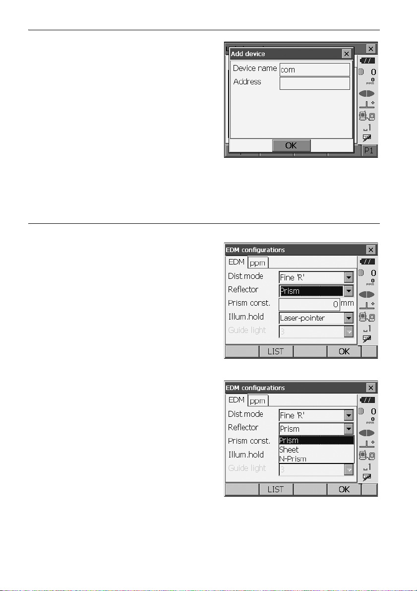
{ESC} Return to previous screen
Example: Entering "computer" (lower case) as the name of a new device
1. Tap the input mode icon in the status bar (second
from bottom) until "_a" is displayed.
2. Press {7} three times.
"c" is displayed.
3. Press {5} three times.
"o" is displayed.
19
Page 26
4. Press {}.
Press {5}. "m" is displayed.
5. Continue to input letters. Press {ENT} to
complete inputting.
Example: selecting a reflector type
(Method 1)
1. Select [EDM] in the first page of Observation
mode or "EDM" in Config mode/Configuration
mode.
Observation mode screen (P.22)
5. BASIC OPERATION
2. Move to "Reflector" using {}/{}/{TAB}.
3. Press {SPACE} to display a list of all options.
4. Select an option using {}/{}.
5. Press {ENT} to confirm selection.
20
Page 27

5. BASIC OPERATION
(Method 2)
1. Select [EDM] in the first page of Measure mode
or "EDM" in Config mode/Configuration mode.
2. Move to "Reflector" using {}/{}/{TAB}.
3. Switch between Prism, Sheet, and N-Prism using
{}/{}.
4. Press {ENT} to confirm selection.
5.2 Display Functions
Screens can be selected/operated using the keys on the keyboard or the touch panel. The touch panel
can be operated using either the stylus pen provided or your fingers.
It is also possible to de-activate the touch panel temporarily.
"20. CHANGING THE SETTINGS"
• Do not scratch the display or use any sharp implement other than the stylus pen to operate the touch
panel.
Using the stylus
The stylus pen can be used to select menus and buttons on the screen and operate the scroll bar.
Temporarily de-activating the touch panel
The touch panel can be temporarily de-activated. This is especially useful when cleaning the display.
To de-activate, tap on the status bar. <Touch panel temporarily de-activated> is displayed.
The touch panel cannot be operated while the above message is displayed. Press {ESC} to cancel
the message and re-activate the touch panel.
21
Page 28
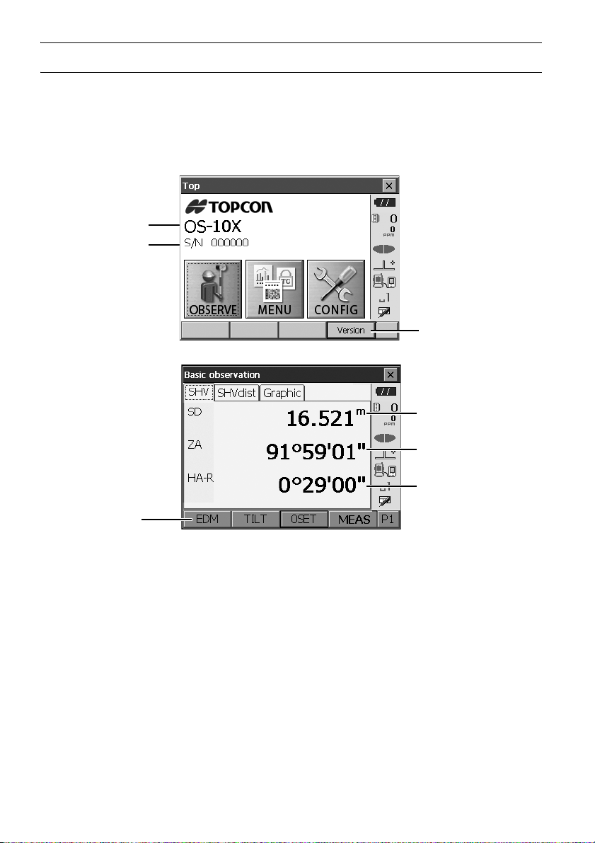
5. BASIC OPERATION
Instrument name
Serial Number
Application software
version
(1) Distance
(2) Vertical angle
(3) Horizontal angle
Softkey
Displaying and operating screens
• To close a screen, tap the cross in the top right corner, or press {ESC}.
• Tabs, softkey allocations, displayed tab items, and character sizes can all be changed in accordance
with user preferences.
"20. CHANGING THE SETTINGS"
Top menu
Observation mode screen SHV tab
(1) Distance
Display status can be switched between SD (slope distance)/HD (horizontal distance)/VD
(vertical distance).
"20.1 Observation Conditions"
(2) Vertical angle
The Vertical angle display can be switched between Zenith (Z=0°)/Horiz (H=0°)/Horiz (H=±90°)
To switch vertical angle/slope in %, press [ZA/%] when allocated to the Observation mode screen.
"20.1 Observation Conditions"
The capitalized letter in the softkey indicates the currently selected mode.
Allocating [ZA/%]: "20.6 Allocating Key Functions"
22
Page 29
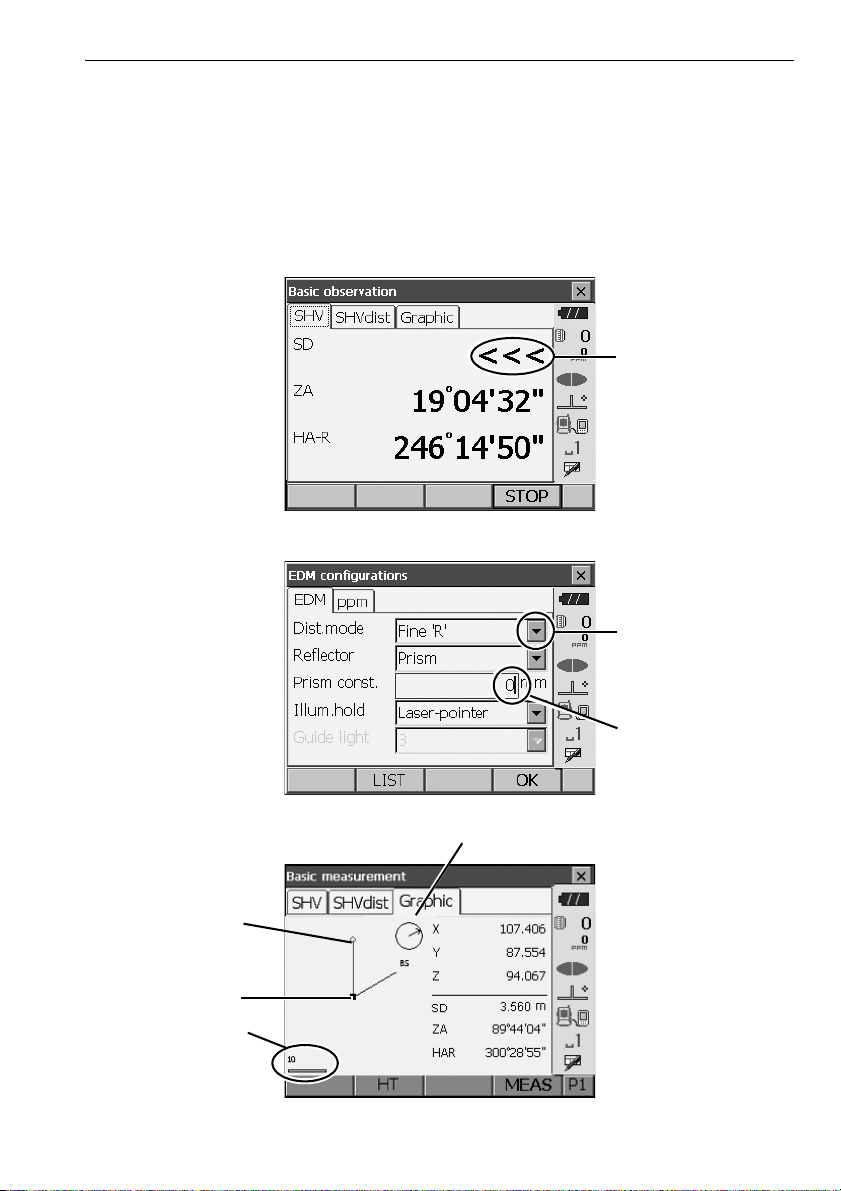
5. BASIC OPERATION
Laser is emitted
Display all options
Values can be input/
edited
Scale
(units: m)
Arrow indicates north as set backsight
Instrument station
Target point
(3)Horizontal angle
Press [R/L] to switch the display status between HA-R (horizontal angle right)/HA-L (horizontal
angle left). The capitalized letter in the softkey indicates the currently selected mode.
Allocating [R/L]: "20.6 Allocating Key Functions"
• Horizontal distance and height difference are also displayed in "SHVdist" tab.
Measuring screen
Input screen/configuration screen
Observation mode screen Graphic tab
23
Page 30
5. BASIC OPERATION
Number
Status bar
The "Graphic" tab display can be modified using the softkeys in the second page.
[CNFG]: In <Graphic configuration> the user can specify the orientation of the "graphic" tab
display and which point, target or station, to set at the center of the display.
[DEF.]: Returns to the original orientation display.
[ZoomIn]: Zooms in.
[ZoomOut]:Zooms out.
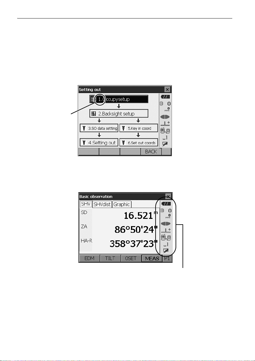
Selecting menus
To select a menu, tap the touch panel or press the relevant number key.
Status bar
Indicates the current status of the instrument. Tapping icons will switch between the relevant
options for that item. Tapping and holding will display a list of all available options for that item and,
in certain cases, a link to the configuration screen for that item.
Allocation of the icons of the status bar corresponds with that of Starkey mode.
About icons: "5.4 Starkey Mode"
24
Page 31

5.3 Inputting Characters using the Input Panel
5. BASIC OPERATION
To d i sp la y <Input Panel>, tap of status bar/Starkey mode or while pressing
keyboard can be used to input numeric and alphabetic characters as well as symbols. Tap the icon
again to close.
{SHIFT} press {α}. This
• When <Input Panel> is covering the icon of the status bar, use the stylus pen to drag the input
panel to another part of the screen so that you can access the icon.
Input panel
Esc : Deletes all input characters
Tab : Moves the cursor to the next text box
CAP : Alternates between upper and lower case alphabetic characters and numbers/
symbols
Shift : Alternates between upper and lower case alphabetic characters and numbers/
symbols. Is canceled after inputting a single character.
Ctl : No function
Del/ : Delete the character to the left/right or deletes the entire text in the active section
←→ : Move the cursor left/right
ENT : Accept input characters
Space : Input a blank space
áü : Accesses further Latin/Germanic characters/symbols. Is canceled after inputting a
single character.
5.4 Starkey Mode
Via Starkey mode, you can jump from each basic mode screen to the screen of checking/changing the
various settings directly. Press starkey {
pressed and hold in the same way with status bar.
• 12 icons allocated in Starkey mode and the above 8 icons correspond with that status bar
• Allocation of the icons can be changed.
★ } to enter Starkey mode. Each icon can be tapped or
Changing allocation of Starkey mode: "20.7 Changing Starkey Mode Icons"
25
Page 32
5. BASIC OPERATION
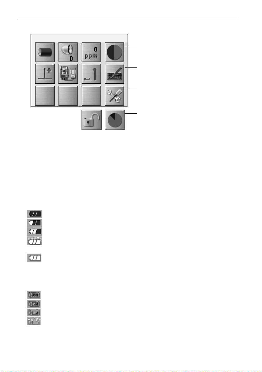
(1) (2) (3) (4)
(5) (6) (7) (8)
(9)
(10) (11)
when instrument was shipped.
10 and 11 are not allocated
Indicates the current status of the instrument.
Tapping icons will switch between the relevant options for that item. Tapping and holding will display
a list of all available options for that item and, in certain cases, a link to the configuration screen for
that item.
Details of each icon are described below. (The numbers correspond to above icons).
(1) Battery icon
Remaining battery power indicator (BDC70/external battery BT-73Q and BT-73QA, Temperature
= 20°C, EDM on).
The remaining battery power displayed when distance measurement is in progress may differ to
that displayed at other times.
: Level 3 Full power
: Level 2 Plenty of power remains
: Level 1 Half or less power remains
Level 0 Little power remains Prepare a replacement battery.
(Flashes red and black)
: No power Stop operation and charge the battery.
(Red display in the center of the screen)
"7.1 Battery Charging"
When using external battery
: Level 3 Full power
: Level 2 Plenty of power remains
: Level 1 Half or less power remains
: Level 0 Little power remains. Prepare a replacement battery.
"7.1 Battery Charging"
26
Page 33
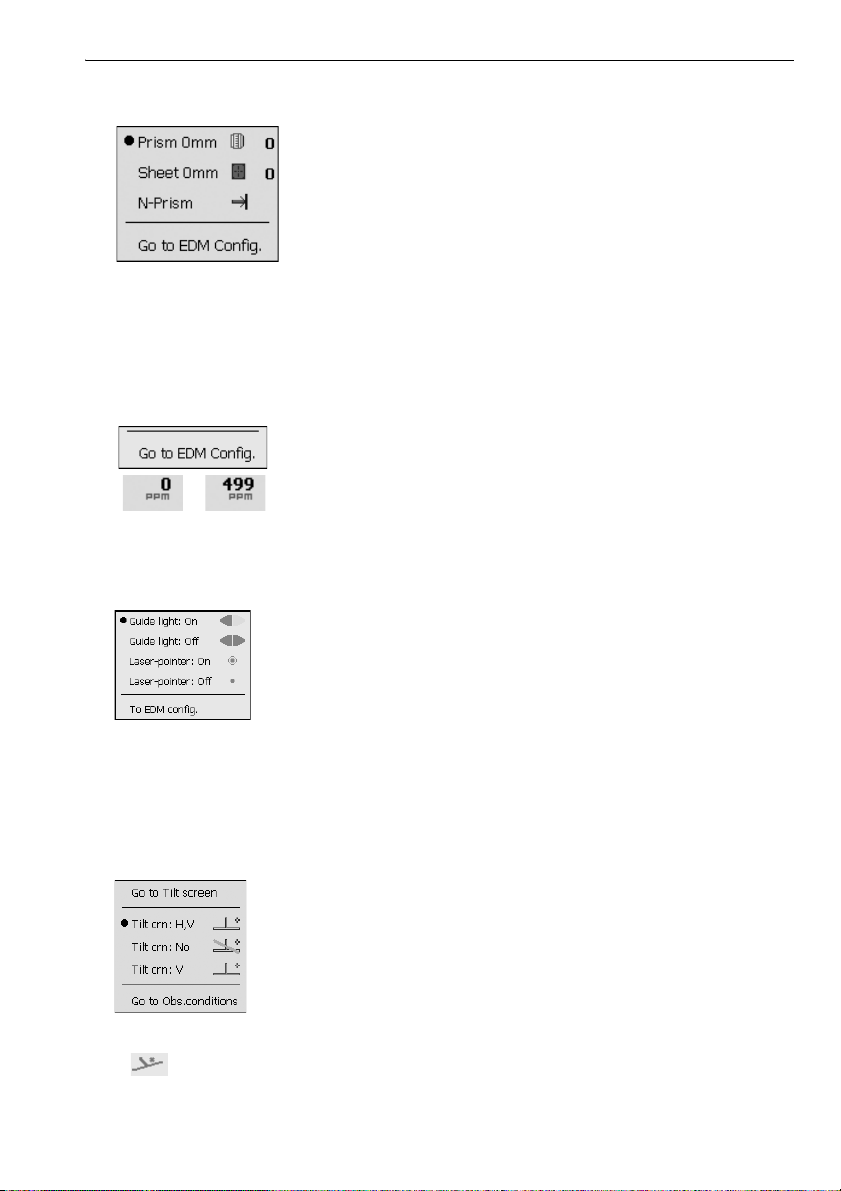
(2) Target type icon
/
Selection of target type and configuration of prism constant.
: Prism (0mm)
: Sheet (0mm)
: N-Prism
Target information can be edited/recorded in <Reflector setting>.
"20.3 EDM Settings"
(3) PPM setting icon
Current atmospheric correction factor setting is displayed.
Configuration of EDM.
(4) Laser-pointer/guide light icon
Configuration of laser-pointer/guide light status.
Switching the laser-pointer/guide light ON/OFF: "5.1 Basic Key Operation"
: Guide light ON
: Guide light OFF
: Laser-pointer ON
: Laser-pointer OFF
5. BASIC OPERATION
• The laser-pointer will be automatically switched OFF during distance measurement.
(5) Tilt angle compensation icon
The vertical and horizontal angles are automatically compensated for small tilt errors using the
OS's dual-axis tilt sensor. This icon displays the status of this function.
: Horizontal and vertical tilt angles compensated (blue)
: No compensation
: Only vertical tilt angle compensated (green)
• is displayed when the instrument is out of level.
27
Page 34
5. BASIC OPERATION
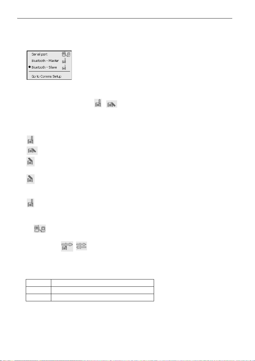
(6) Communication status with external devices icon
Selection and configuration of communication status with external devices. This icon is not
displayed in Program mode. Bluetooth settings can only be selected when using instruments
incorporating the Bluetooth module.
: Connection via RS232C cable
: Connection via Bluetooth wireless technology (OS set as "Master"
device) (blue antenna)
: Connection via Bluetooth wireless technology (OS set as "Slave" device)
(green antenna)
• When Bluetooth communication is selected (OS set as "Master" device) a connection can be
initiated/canceled by tapping / .
Connection status to external devices is displayed as follows.
i) Connection via Bluetooth wireless technology
When OS is set as the "Master" device the antenna icon is blue. When the OS is set as the
"Slave" device the antenna icon is green.
: Connecting
: Canceling connection
: (Antenna is purple - moving)
Inquiring about other Bluetooth devices
: (Antenna is purple - stationary)
Communication settings in progress/Preparing for communication (Instrument just
powered ON or just switched to "Slave")
: Connection error (icon flashes) (the color depends on the setting)
ii) : Connection via RS232C cable
• An arrow (e.g. / ) is displayed to indicate that data transmission is in progress. A red
arrow indicates that data transmission has failed and data needs to be sent again.
(7) Input mode icon
Selection of input mode
_1 Inputting numbers and symbols
_a Inputting lower case alphabetic characters
_A Inputting upper case alphabetic characters
"5.3 Inputting Characters using the Input Panel Inputting letters/figures"
(8) Input panel icon
"5.3 Inputting Characters using the Input Panel"
28
Page 35
5. BASIC OPERATION
(9) Config mode icon
Switch to Config mode.
"20. CHANGING THE SETTINGS"
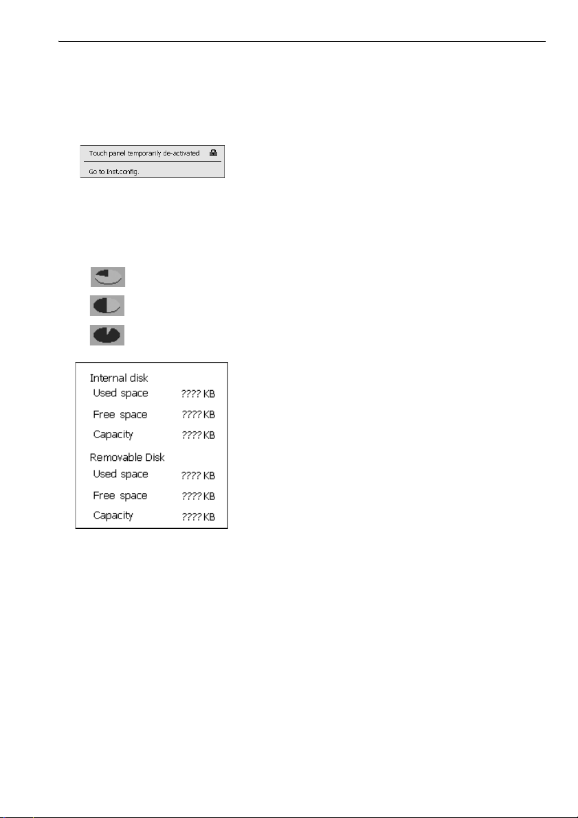
(10) Touch panel icon
De-activate the touch panel temporarily or go to Inst.config.
: Touch panel temporarily de-activated.
• This icon cannot be operated during distance measurement, or during data transmission.
(11) Disk usage icon
Tap and hold disk icon to check the detail of the disk usage.
:Less than 20%
:20 to 50%
:More than 50%
Internal Disk
Used space: Usage space of disk capacity of the instrument
Free space: Free space of disk capacity of the instrument
Capacity: Disk capacity of the instrument
Removable Disk
Used space: Usage space of disk capacity of the external disk connected to the
instrument
Free space: Free space of disk capacity of the external disk connected to the
Capacity: Disk capacity of the external disk connected to the instrument
instrument
• "Removable Disk" is displayed only when an external disk is connected to the instrument.
29
Page 36
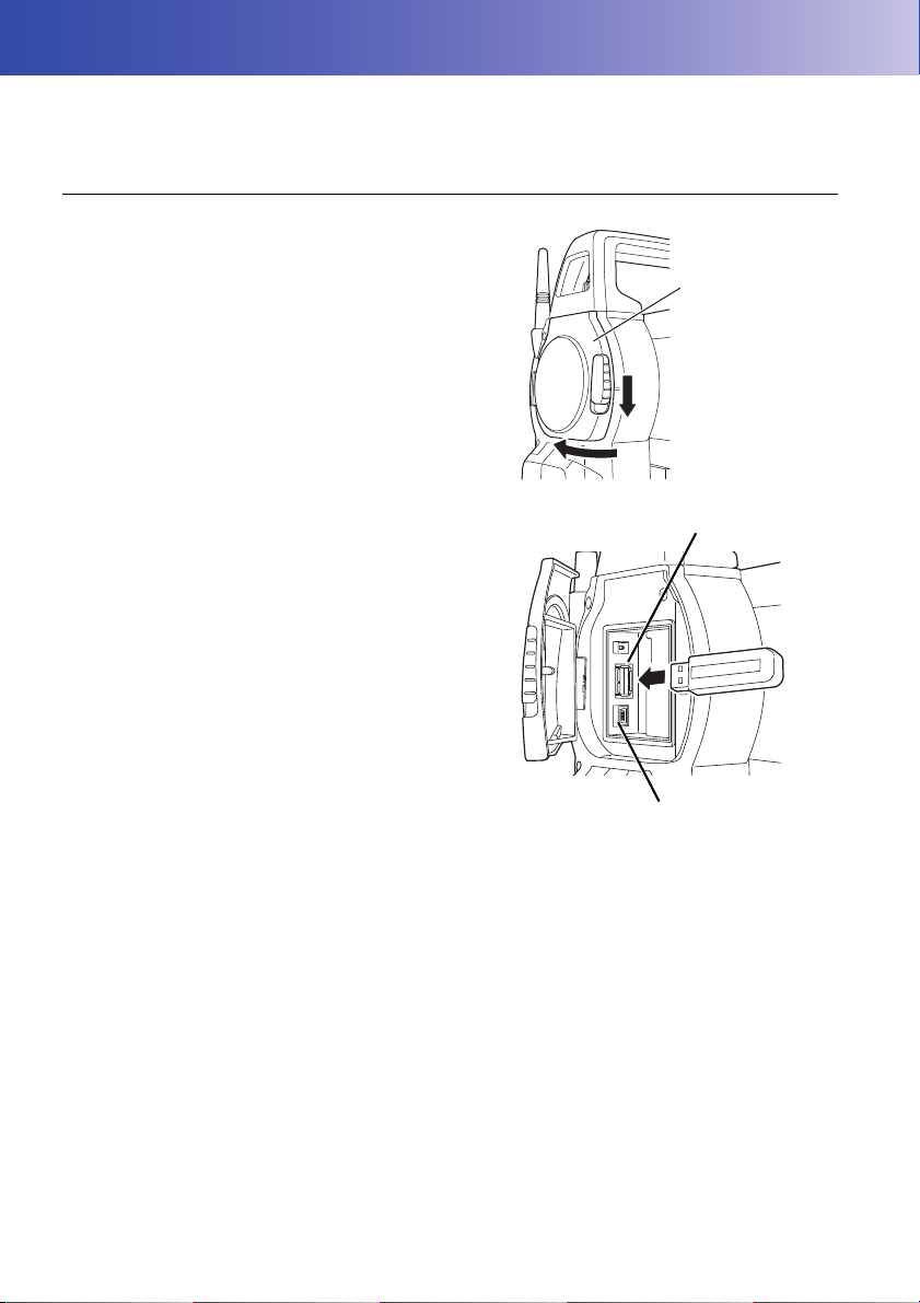
6. INSERTING USB MEMORY
External interface
hatch
USB Port 1
USB Port 2
• When reading/writing data, do not remove the USB memory.
PROCEDURE
1. Open the external interface hatch by sliding its
button.
2. Insert the USB memory into the USB port 1.
• When using a USB memory with 4 metal
terminals on the surface, insert it with the
terminal facing backwards to avoid damaging
the USB port.
3. Close the external interface hatch until a click
is heard.
30
Page 37
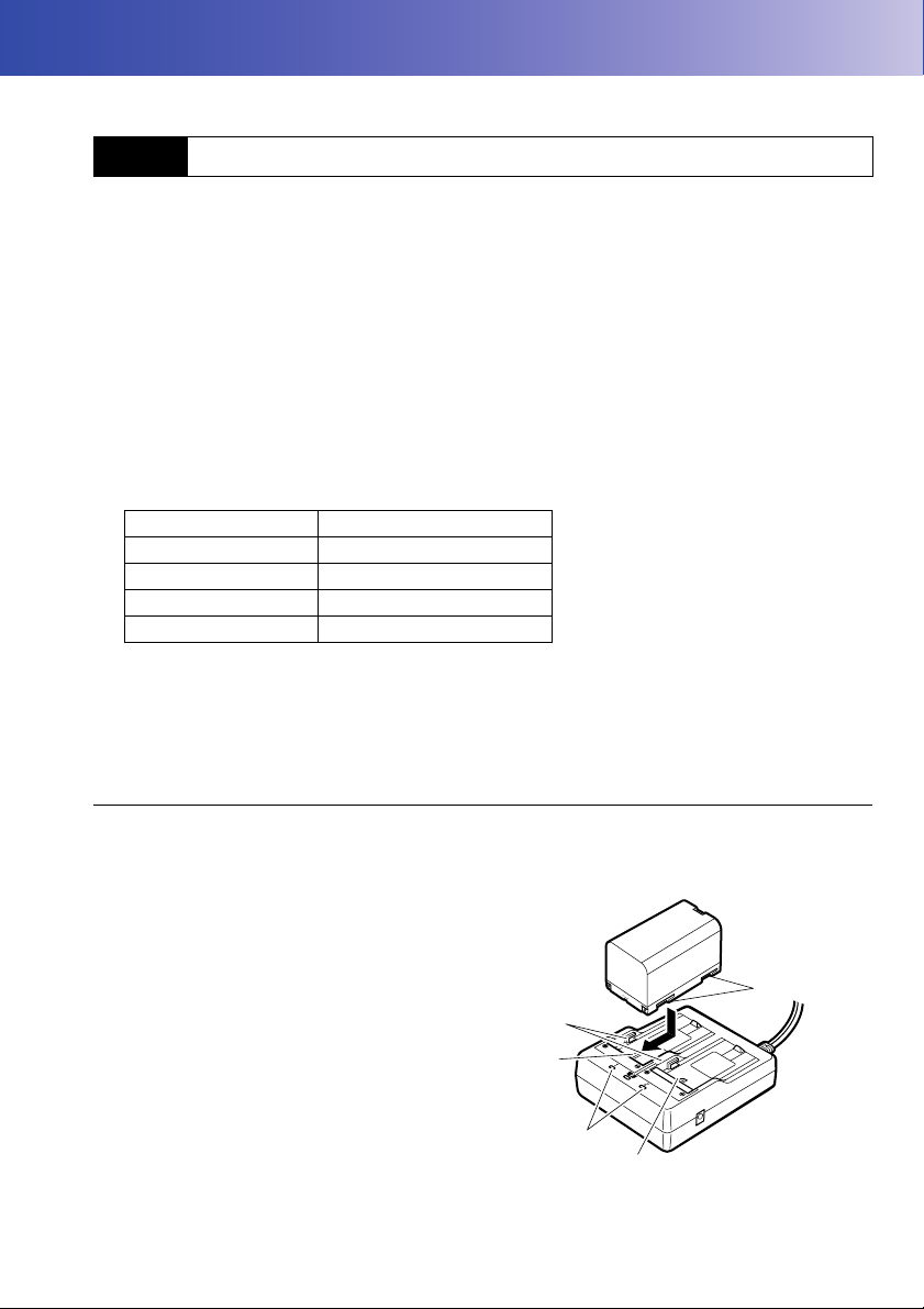
7. USING THE BATTERY
Guides
Slot 1
Slot 2
Charging
lamp
Grooves
Types of power source: "23. POWER SUPPLY SYSTEM"
7.1 Battery Charging
The battery was not charged at the factory. Charge the battery fully before using the OS.
• The charger will become rather hot during use. This is normal.
• Do not use to charge batteries other than those specified.
• The charger is for indoor use only. Do not use outdoors.
• Batteries cannot be charged, even when the charging lamp is flashing, when the temperature is
outside the charging temperature range.
• Do not charge the battery just after charging is completed. Battery performance may decline.
• Remove batteries from the charger before putting into storage.
• When not in use, disconnect the power cable plug from the wall outlet.
• Store the battery in a dry room where the temperature is within the following ranges.
Storage period Temperature range
1 week or less -20 to 50°C
1 week to 1 month -20 to 45°C
1 month to 6 months -20 to 40°C
6 months to 1 year -20 to 35°C
For long-term storage, the battery should be charged at least once every six months.
• Batteries generate power using a chemical reaction and as a result have a limited lifetime. Even
when in storage and not used for long periods, battery capacity deteriorates with the passage of
time. This may result in the operating time of the battery shortening despite having been charged
correctly. In this event, a new battery is required.
PROCEDURE
1. Connect the power cable to the charger and
plug the charger into the wall outlet.
2. Mount the battery in the charger by matching
the grooves on the battery with the guides on
the charger.
31
Page 38
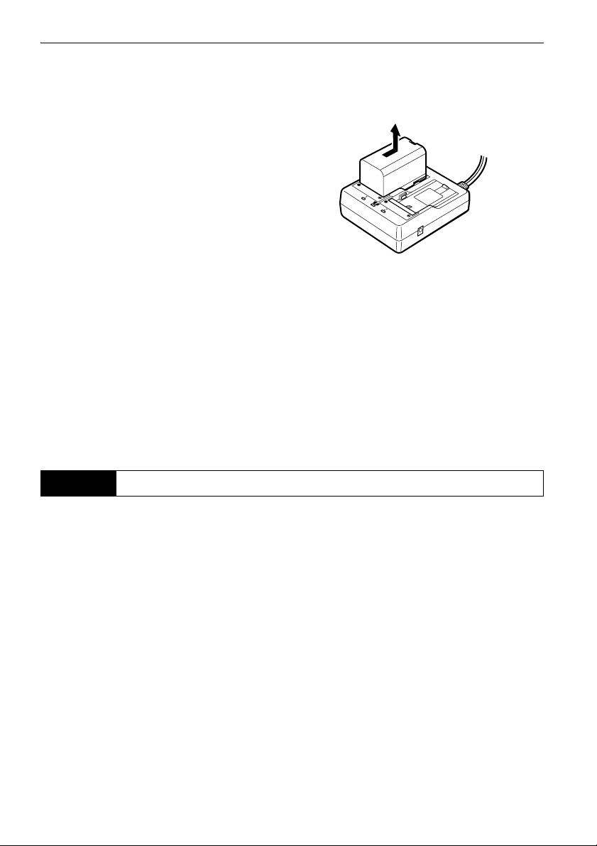
7. USING THE BATTERY
3. When charging starts, the lamp starts blinking.
4. The lamp lights when charging is finished.
5. Remove the battery and unplug the charger.
• Slots 1 and 2:
The charger starts charging the battery mounted first. If you place two batteries in the charger, the
battery in slot 1 is charged first, and then the battery in slot 2. ( step 2)
• Charging lamp:
The charging lamp is off when the charger is outside the charging temperature range or when the
battery is mounted incorrectly. If the lamp is still off after the charger falls within its charging
temperature range and the battery is mounted again, contact your local dealer. (steps 2 and 3)
• Charging time per battery:
BDC70:about 5.5 hours (at 25°C)
(Charging can take longer than the times stated above when temperatures are either especially high
or low).
7.2 Installing/Removing the Battery
Mount the charged battery.
• Use the attached battery (BDC70).
• Before removing the battery, turn off the power to the instrument. If the battery is removed while the
power is switched on, a warm boot may occur. File and folder data may be lost as a result.
• Do not open the battery cover while the power is on.
• When installing/removing the battery, make sure that moisture or dust particles do not come in
contact with the inside of the instrument.
• Remove batteries from the surveying instrument or charger before putting into storage.
32
Page 39
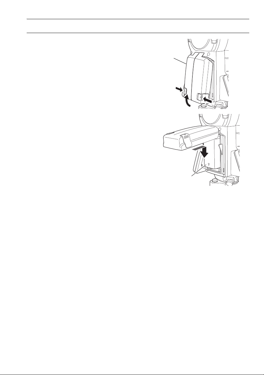
PROCEDURE Mounting the battery
Battery cover
Battery
1. Slide down the catches on the battery cover to
open.
2. Insert the battery in the direction of the arrow
on the side of the battery.
• Do not insert the battery inclined. Doing so
may damage the instrument or battery
terminals.
3. Close the battery cover. A click is heard when
the cover is secure.
7. USING THE BATTERY
33
Page 40
8. SETTING UP THE INSTRUMENT
Centering screw
Focussing on the survey point
Focussing on
the reticle
• Mount the battery in the instrument before performing this operation because the instrument will tilt
slightly if the battery is mounted after levelling.
8.1 Centering
PROCEDURE Centering with the optical plummet eyepiece
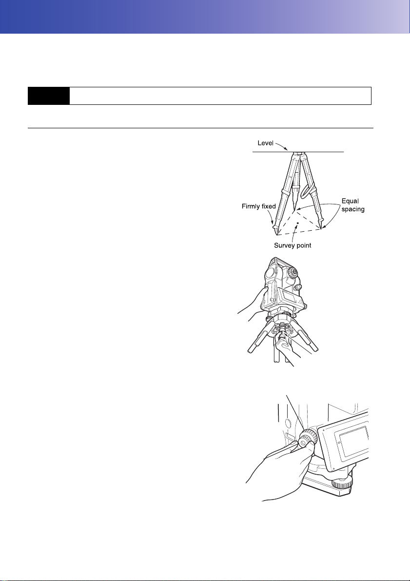
1. Make sure the legs are spaced at equal intervals
and the head is approximately level.
Set the tripod so that the head is positioned over
the survey point.
Make sure the tripod shoes are firmly fixed in the
ground.
2. Place the instrument on the tripod head.
Supporting it with one hand, tighten the centering
screw on the bottom of the unit to make sure it is
secured to the tripod.
3. Looking through the optical plummet eyepiece, turn
the optical plummet eyepiece to focus on the
reticle.
Turn the optical plummet focussing ring to focus on
the survey point.
34
Page 41
8. SETTING UP THE INSTRUMENT
PROCEDURE Centering with the laser plummet (Option)
1. Set up the tripod and affix the instrument on the
tripod head.
"8.1 Centering"
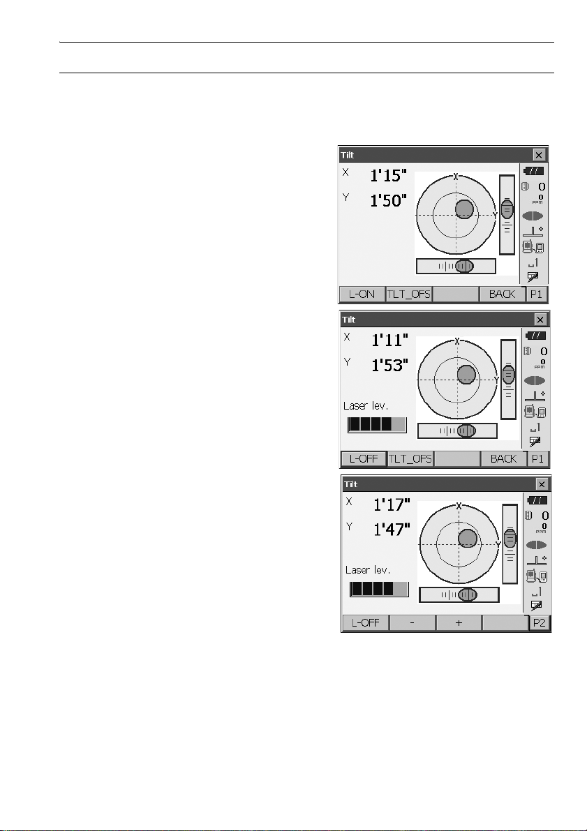
2. Press {ON} to power on
"9. POWER ON/OFF"
The electric circular level (tilt) is displayed on the
screen.
3. Press [L-ON].
The laser plummet beam will be emitted from the
bottom of the instrument.
4. Use [-]/[+] on the second page to adjust the
brightness of the laser.
5. Adjust the position of the instrument on the tripod
until the laser beam is aligned with the center of the
survey point.
6. Press [L-OFF] to turn the laser plummet off.
Alternatively, press {ESC} to return to another
screen. The laser plummet will switch off
automatically.
35
Page 42

8. SETTING UP THE INSTRUMENT
Tripod legs
adjustment
• Visibility of the laser spot may be affected when operating in direct sunlight. In this event, provide
shade for the survey point.
8.2 Levelling
PROCEDURE
1. Adjust the levelling foot screws to center the
survey point in the optical plummet reticle.
2. Center the bubble in the circular level by either
shortening the tripod leg closest to the offcenter
direction of the bubble or by lengthening the
tripod leg farthest from the offcenter direction of
the bubble. Adjust one more tripod leg to center
the bubble.
Turn the levelling foot screws while checking the
circular level until the bubble is centered in the
center circle.
3. Press {} to power on.
"9. POWER ON/OFF"
The electric circular level is displayed on the
<Tilt>.
“” indicates the bubble in circular level. The
range of the inside circle is ±1.5' and the range of
the outside circle is ±6'.
4. Center “” in the circular level.
When the bubble is in the center, proceed to
step 7.
36
Page 43

5. Turn the instrument until the telescope is parallel
to a line between levelling foot screws A and B.
6. Set the tilt angle to 0° using foot screws A and B
for the X direction and levelling screw C for the Y
direction.
7. Loosen the centering screw slightly.
Looking through the optical plummet eyepiece, slide
the instrument over the tripod head until the survey
point is exactly centered in the reticle.
Retighten the centering screw securely.
If the instrument is levelled using laser plummet,
emit the laser plummet beam and check it again.
"8.1 Centering PROCEDURE Centering with
the laser plummet (Option)"
8. Check again to make sure the bubble in the electric
circular level is centered.
If not, repeat the procedure starting from step 6.
9. Press {ESC} to return to Observation mode.
8. SETTING UP THE INSTRUMENT
37
Page 44

9. POWER ON/OFF
• When the power cannot be switched ON or the power is soon turned OFF even though the battery
is mounted, there may be almost no battery power remaining. Replace it with a fully charged battery.
"21. WARNING AND ERROR MESSAGES"
PROCEDURE Power ON
1. Press {}.
When the power is switched on, the <Tilt> is
displayed.
"8.2 Levelling" step 3
Press {ESC} to go to Observation mode.
If "Out of range" is displayed, the instrument tilt
sensor is indicating that the instrument is out of level.
Level the instrument once again using circular level,
then display <Tilt>.
Press and hold Tilt angle compensation icon on
status bar or in Starkey mode, then select "Go to Tilt
screen".
"5.4 Starkey Mode" (5) Tilt angle compensation
icon
• "Tilt crn." in "Obs. condition" should be set to "No" if the display is unsteady due to vibration or strong
wind.
"20.1 Observation Conditions"
Resume function
The Resume function redisplays the screen appearing before the instrument was powered OFF
when the instrument is powered back ON. All parameter settings are also saved. Even if
remaining battery power is completely depleted, this function will remain active for 1 minute,
after which it is canceled. Replace a depleted battery as soon as possible.
PROCEDURE Power OFF
Press {} and hold (about 1sec).
• When there is almost no battery power remaining,
the battery icon in the status bar will start to blink.In
this event, stop measurement, switch off the power
and charge the battery or replace with a fully
charged battery.
• To save power, power to the OS is automatically cut
off if it is not operated for a fixed period of time. This
time period can be set in "Power off" in
<Inst.config.>.
"20.2 Instrument Configuration"
38
Page 45

9. POWER ON/OFF
9.1 Configuring the Touch Panel
When using for the first time, or after performing a cold
boot, the screen for configuring the touch panel will be
displayed.
Follow the instructions on the screen. Tap the crosshairs at the center of the display with the stylus pen.
Tap 5 times. Press {ENT} to complete touch panel
configuration. Press {ESC} to retain previous settings.
• Touch panel configuration can be performed at any
time during normal operation by pressing [PNL
CAL] in <Inst.config.>.
"20.2 Instrument Configuration"
9.2 Resolving Software Issues
If you are experiencing problems with the OS and suspect a fault in the program, you should try a
warm boot. If the problem is not resolved with a warm boot the next step is to perform a cold boot.
A warm boot will not erase surveying data in OS but will cancel the resume function. Whenever
possible transmit the data to a personal computer before rebooting.
PROCEDURE
1. Power OFF the instrument.
2. Press { } while pressing {ENT}.
The instrument is reset and powers ON as
normal.
Cold boot
If the problem is not resolved with a warm boot the next step is to perform a cold boot. A cold
boot will not erase surveying data in OS but all the parameters will be changed to the factory
settings. If the data in the memory is necessary, BE SURE TO TRANSFER IT TO A
PERSONAL COMPUTER BEFORE PERFORMING A COLD BOOT.
To perform a cold boot, while holding {}, and {S.P.}, press
The instrument is reset and powers ON as normal.
"20.11 Restoring Default Settings"
39
{}
.
Page 46

9. POWER ON/OFF
Reset button
Problems Powering OFF
When the instrument cannot be powered OFF as normal, depress the reset button with the tip
of the stylus pen.
• Pressing the Reset button may result in file and folder data being lost.
40
Page 47

10.CONNECTING TO EXTERNAL DEVICES
The OS supports Bluetooth wireless technology, USB and RS232C for communication with data
collectors etc. Inputting/outputting data is also possible by inserting a USB memory or by connecting
to a USB device.
Read this manual in conjunction with the operator’s manual for the relevant external device.
• Bluetooth communication is only possible with instruments incorporating the Bluetooth module.
• When doing Bluetooth communication, read "4.3 Bluetooth Wireless Technology"
10.1 Wireless Communication using Bluetooth Technology
The Bluetooth module incorporated in the OS can be used for communication with Bluetooth devices
such as data collectors.
Bluetooth connection mode
Communication between a pair of Bluetooth devices requires one device to be set as the
"Master" and the other as the "Slave". To initiate connections from the OS side, set the OS as
the "Master" device. To initiate connections from the paired device side, set the OS as the
"Slave" device. Always set the OS to "Slave" when connecting with a data collector to perform
measurements and to record the data. Only "Slave" can be selected when the instrument is
shipped.
PROCEDURE Set Bluetooth communication mode to "Slave"
1. Select "Comms" in Config mode.
41
Page 48
10. CONNECTING TO EXTERNAL DEVICES
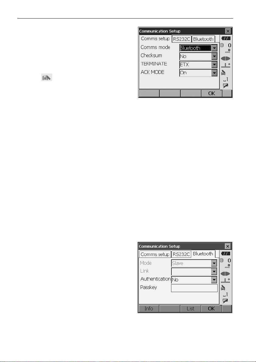
Set Comms mode in the "Comms setup" tab to
"Bluetooth".
• Changing communication settings during
Bluetooth communication will cancel the
connection.
• The status bar icon cannot be tapped in
<Communication Setup>.
• No changes for the setting' (2) to (4) from the
factory setting are necessary as long as
connecting to a recommended program on the
data collector. If connection can not be
established, check the communication settings
of OS and the data collector.
• Setting’ (3) and (4) are for an instrument using
GTS commands.
Items set and options (*: Factory setting)
(1) Communication mode RS232C*/Bluetooth
(2) Check sum yes/No*
(3) Terminate ETX*/ETX+CR/ETX+CR+LF
(4) Ack mode Off/On*
Termina te
Select the option Off or On for carrige return (CR) and line feed when collecting measurement
data with a computer.
ACK mode
When communicating to an external device, the protocol for handshaking can omit the [ACK]
coming from the external device so data is not sent again.
On: Standard
Off: Omit the [ACK]
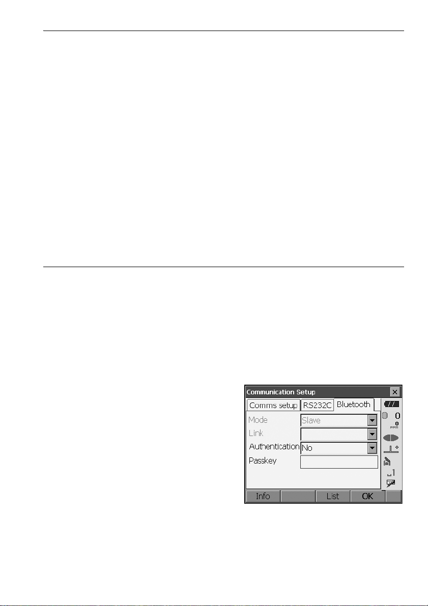
2. Check that "Mode" in the "Bluetooth" tab is set to
"Slave".
• Only "Slave" can be selected when the
instrument is shipped.
42
Page 49
10. CONNECTING TO EXTERNAL DEVICES
3. Set "Authentication" to "Yes" or "No".
If "Authentication" is set to "Yes" for the OS the
passkey will also need to be input on the
companion device.
4. When "Authentication" is set to "Yes", input the
same passkey as that for the intended companion
device. Even if "Authentication" is set to "No", a
passkey is requested when authentication is set
on the companion device being used.
• Up to 16 numeral characters can be input. Input
characters will be displayed as asterisks (e.g.
"*****"). The passkey was set to "0123" at the
factory.
5. Press [OK] to finish settings. Move on to the
Bluetooth communication.
"10.2 Communication between the OS and
Companion Device"
PROCEDURE Set Bluetooth communication mode to "Master"
• When setting communication mode to "Master", companion devices should be registered first. If
companion devices have already been registered, proceed to step 6.
1. Power on the companion device to be registered.
2. Select "Bluetooth" in "Comms mode".
"PROCEDURE Set Bluetooth
communication mode to "Slave"" Step1
3. Press [LIST] to display a list of all registered
devices (no devices are registered when the
instrument is shipped).
43
Page 50
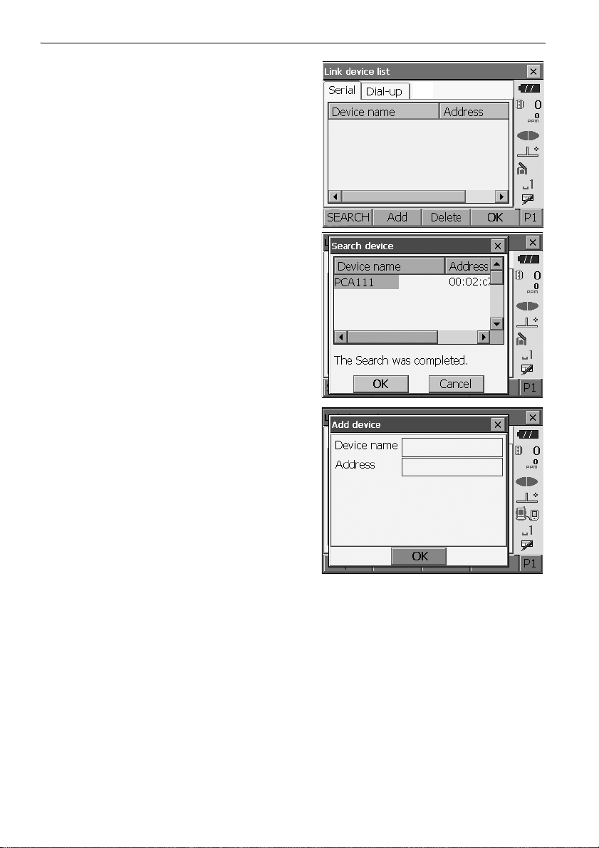
4. Press [SEARCH] in the "Serial" tab to search
about communication-ready Bluetooth devices in
the immediate vicinity of the instrument.
When the search is completed, their device name
and address are displayed in a list. Select a device
from this list and press [OK] to add to the Link
device list.
• Maximum number of devices registered: 6
press
When registering a device manually,
to display <Add device>. Input the device name
and Bluetooth address and press [OK]
should be 12 characters (numbers 0 to 9 and
letters from A to F) in length
.
[Add]
.
Address
10. CONNECTING TO EXTERNAL DEVICES
•Press [Delete] to delete the selected device
name. Deleted device names cannot be
retrieved.
• Select a device and press [Edit] in the second
page to update the device name and/or device
address.
5. Press [OK] to complete registration.
44
Page 51
10. CONNECTING TO EXTERNAL DEVICES
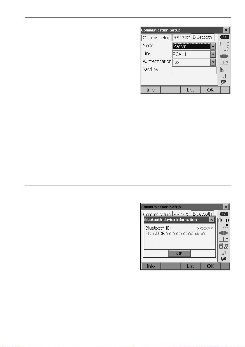
6. Set "Mode" in the "Bluetooth" tab to "Master".
7. Select a companion device from among the
Bluetooth devices already registered in "Link".
8. Set "Authentication" to "Yes" or "No".
"PROCEDURE Set Bluetooth
communication mode to "Slave"" Steps 3 to
4
9. Press [OK] to finish settings. Move on to the
Bluetooth communication.
"10.2 Communication between the OS and
Companion Device"
PROCEDURE Displaying Bluetooth information for the OS
1. Select "Comms" in Config mode.
2. Press [Info] in the "Bluetooth" tab to display
information for the OS. Register the Bluetooth
address (BD ADDR) displayed here in the paired
device set as "Master".
Bluetooth device address
This is a number unique to one particular Bluetooth device used to identify devices during
communication. This number consists of 12 characters (numbers 0 to 9 and letters from A to F).
Some devices may be referred to by their Bluetooth device address.
45
Page 52

10. CONNECTING TO EXTERNAL DEVICES
10.2 Communication between the OS and Companion Device
• Bluetooth communication causes OS battery power to be depleted at a rate higher than that for
normal operation.
• Check that the companion device (data collector, computer, or cellular phone etc.) is turned on and
the relevant Bluetooth settings are complete.
• All communication settings will be changed to factory settings when a cold boot is performed.
Comms setup will need to be performed again.
"10.1 Wireless Communication using Bluetooth Technology"
• Always set the OS to "Slave" when connecting with a data collector to perform measurements and
to record the data. When the OS is set as the "Slave" device, the establishing of a connection can
only be initiated/canceled by the companion device set as "Master".
PROCEDURE Bluetooth communication as "Slave"
1. Complete the necessary OS settings for
Bluetooth communication.
"10.1 Wireless Communication using
Bluetooth Technology" " PROCEDURE Set
Bluetooth communication mode to "Slave""
2. Start communication by the data collector.
Manual of the program mounted on the data
collector
3. Terminate the connection by the data collector.
PROCEDURE Bluetooth communication as "Master"
1. Complete the necessary OS settings for
Bluetooth communication.
"10.1 Wireless Communication using
Bluetooth Technology "PROCEDURE Set
Bluetooth communication mode to "Master""
46
Page 53

2. Start communication
When OS is set as the "Master" device, the
[Connect] softkey is allocated to the fourth page
of Observation mode. When [Connect] is pressed
the OS searches for the device selected in "Link"
and a connection starts. When a connection has
been successfully established is displayed in
the status bar.
The establishing of a connection can also be
initiated by tapping in the status bar or in
Starkey mode.
Communication status:"5.4 Starkey Mode"
3. Press [Cancel] in the fourth page of Observation
mode to terminate the connection.
A connection can also be terminated by tapping
in the status bar.
10. CONNECTING TO EXTERNAL DEVICES
47
Page 54
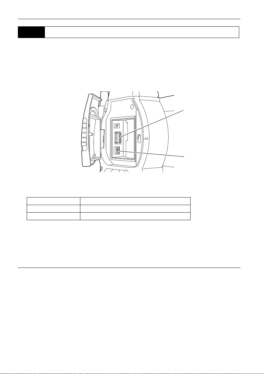
10. CONNECTING TO EXTERNAL DEVICES
USB port 1
USB port 2
10.3 Connecting to USB devices
OS has two different USB ports.
• TOPCON CORPORATION cannot guarantee that all USB devices are compatible with the OS USB
ports.
• Use a computer WindowsXP/Vista/7 is based and USB connection is capable.
Each port is used for connection to different types of devices.
Port name Device type
USB port 1 USB memory devices
USB port 2 (mini-B) computers etc.
Using USB port 2, the instrument and a computer can be communicated. There are USB mode and
Mobile mode.
• Remove the USB cable from USB port 2 carefully to avoid damaging the cable.
Connecting the OS to a computer to transfer data from OS
• As for the download and install of "exFat file system driver"/ActiveSync/Windows Mobile Device
Center, please access to Microsoft support site.
USB mode connection
When connecting Windows XP, "exFat file system driver" needs to be installed to the computer.
48
Page 55
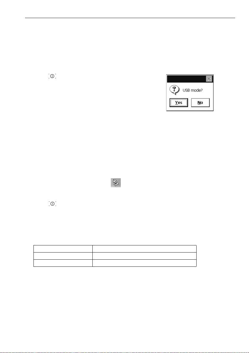
1. Power OFF the OS. Connect the OS and
computer using the USB cable.
"9. POWER ON/OFF"
• The computer does not need to be turned OFF
before connection.
2. Press { } while pressing {ENT} to display a
message box asking whether to boot USB mode,
then press [YES].
The screen of the instrument will be <USB Mode>.
• OS may not be displayed as <Removable Disk>.
It depends on Windows settings.
Follow the instructions below to ensure that the
OS continues to operate normally during USB
transfer.
• Do not change the folder hierarchy or folder
names in <Removable Disk>.
• Do not format the "removable disk" on the
computer.
3. Perform "Safely Remove Hardware" in the
task bar and disconnect the USB cable.
10. CONNECTING TO EXTERNAL DEVICES
4. Press {} and hold (about 1sec) to turn off the
instrument to exit USB mode connection.
Mobile mode connection
A synchronous software needs to be installed to the computer depending on the Windows
version.
Computer to connect Synchronous software
Windows XP ActiveSync
Windows vista/7 Windows Mobile Device Center
1. Power OFF the OS. Connect the OS and
computer using the USB cable.
"9. POWER ON/OFF"
• The computer does not need to be turned OFF
before connection.
49
Page 56

2. Press { } while pressing {ENT} to display a
message box asking whether to boot USB mode,
then press [NO].
The synchronous software is effective.
• OS may not be displayed as <Removable Disk>.
It depends on Windows settings.
Follow the instructions below to ensure that the
OS continues to operate normally during USB
transfer.
• Do not change the folder hierarchy or folder
names in <Removable Disk>.
• Do not format the "removable disk" on the
computer.
3. If synchronous software displays a partner setting
screen on the computer and asks whether to set a
partner device, press [NO].
• A partner setting screen may not be displayed
depending on the synchronous software
settings.
10. CONNECTING TO EXTERNAL DEVICES
4. Disconnect the USB cable to exit mobile mode
connection.
50
Page 57
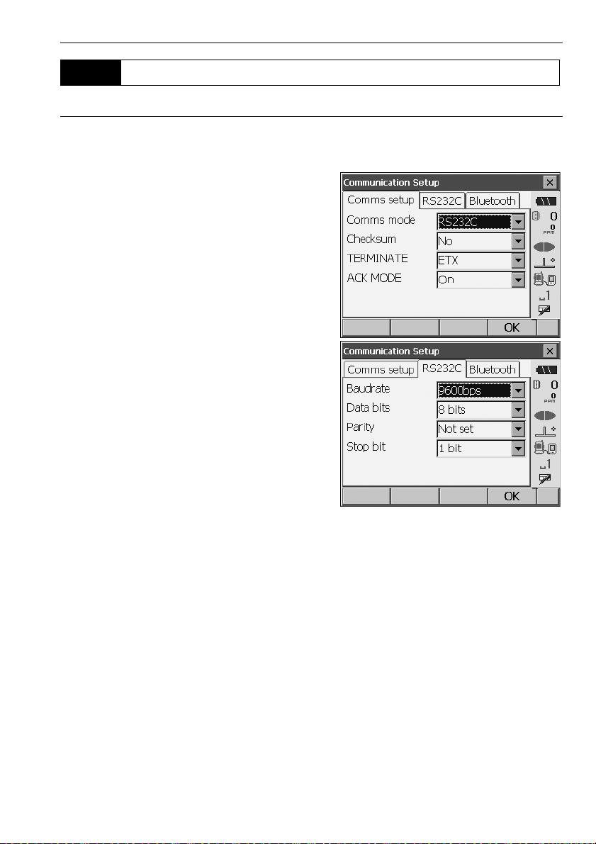
10.4 Connection via RS232C cable
PROCEDURE Basic cable settings
1. Connect the cable.
Cables: "25. OPTIONAL ACCESSORIES"
2. Select "Comms" in Config mode.
Set communication conditions in the "Comms
setup" tab. Set "Comms mode" to "RS232C".
3. Set options in the "RS232C" tab according to the
selection made in the "Comms setup" tab.
*: factory settings
Baud rate: 1200/2400/4800/
9600*/19200/
38400bps
Data bits: 7/8* bits
Parity: Not set*/Odd/Even
Stop bit: 1*/ 2 bits
10. CONNECTING TO EXTERNAL DEVICES
51
Page 58

11.FOCUSSING AND TARGET SIGHTING
• When sighting the target, strong light shining directly into the objective lens may cause the
instrument to malfunction. Protect the objective lens from direct light by attaching the lens hood.
Observe to the same point of the reticle when the telescope face is changed.
PROCEDURE
1. Focus on the reticle
Look through the telescope eyepiece at a bright
and featureless background.
Turn the eyepiece screw clockwise, then
counterclockwise little by little until just before
the reticle image becomes focussed.
Using these procedures, frequent reticle
refocussing is not necessary since your eye is
focussed at infinity.
2. Sight the target
Loosen the vertical and horizontal clamps, then
use the sighting collimator to bring the target
into the field of view. Tighten both clamps.
3. Focus on the target
Turn the telescope focussing ring to focus on
the target.
Turn the vertical and horizontal fine motion
screws to align the target with the reticle.
The last adjustment of each fine motion screw
should be in the clockwise direction.
4. Readjust the focus until there is no parallax
Readjust the focus with the focussing ring until
there is no parallax between the target image
and the reticle.
Eliminating parallax
This is the relative displacement of the target image with respect to the reticle when the
observer’s head is moved slightly before the eyepiece.
Parallax will introduce reading errors and must be removed before observations are taken.
Parallax can be removed by refocussing the reticle.
52
Page 59

12.ANGLE MEASUREMENT
This section explains the procedures for basic angle measurement in Observation mode.
• It is possible to allocate softkeys in measurement menus to suit various applications and the ways
that different operators handle the instrument.
"20.6 Allocating Key Functions"
12.1 Measuring the Horizontal Angle between Two Points
(Horizontal Angle 0°)
Use the “0SET” function to measure the included angle between two points. The horizontal angle can
be set to 0 at any direction.
PROCEDURE
1. Sight the first target as at right.
"11. FOCUSSING AND TARGET SIGHTING"
2. In the first page of Observation mode, press
[0SET].
[0SET] will flash, so press [0SET] again.
The horizontal angle at the first target becomes 0°.
3. Sight the second target.
The displayed horizontal angle (HA-R) is the
included angle between two points.
53
Page 60

12. ANGLE MEASUREMENT
Current angle
12.2 Setting the Horizontal Angle to a Required Value
(Horizontal Angle Hold)
You can reset the horizontal angle to a required value and use this value to find the horizontal angle
of a new target.
PROCEDURE
1. Sight the first target.
2. In the second page of Observation mode, press
[H-SET]. <Set H angle> is displayed.
3. Enter the angle you wish to set, then press [OK].
The value that is input as the horizontal angle is
displayed.
• The same setting can also be performed with
coordinate and azimuth input.
"14.2 Azimuth Angle Setting"
4. Press [OK] to confirm the input value and display
the new horizontal angle.
5. Sight the second target.
The horizontal angle from the second target to the
value set as the horizontal angle is displayed.
• Pressing [HOLD] performs the same function as above.
•Press [HOLD] to set the displayed horizontal angle. Then, set the angle that is in hold status to the
direction you require.
Allocating [HOLD]: "20.6 Allocating Key Functions"
54
Page 61

12. ANGLE MEASUREMENT
12.3 Angle measurement and Outputting the Data
The following explains angle measurement and the features used to output measurement results to a
computer or other external devices.
"10. CONNECTING TO EXTERNAL DEVICES", Cables: "25. OPTIONAL ACCESSORIES",
Output format and command operations: "Communication manual"
PROCEDURE
1. Connect OS and external device.
2. Allocate the [HVOUT-T] or [HVOUT-S] softkey to
the Observation mode screen.
"20.6 Allocating Key Functions"
• Pressing the softkey outputs data in the following
format.
[HVOUT-T] : GTS format
[HVOUT-S] : SET format
3. Sight the target point.
4. Press [HVOUT-T] or [HVOUT-S].
Output measurement data to peripheral
equipment.
55
Page 62

13.DISTANCE MEASUREMENT
Perform the following settings as preparation for distance measurement in Observation mode.
• Distance measurement mode
• Target type
• Prism constant correction value
•ppm
•EDM ALC
"20.2 Instrument Configuration"
• It is possible to allocate softkeys in measurement menus to suit various applications and the ways
that different operators handle the instrument.
"20.6 Allocating Key Functions"
Caution
• When using the laser-pointer function, be sure to turn OFF the output laser after distance
measurement is completed. Even if distance measurement is canceled, the laser-pointer function is
still operating and the laser beam continues to be emitted.
• Make sure that the target setting on the instrument matches the type of target used. OS
automatically adjusts the intensity of the laser beam and switches the distance measurement
display range to match the type of target used. If the target does not correspond to the target
settings, accurate measurement results cannot be obtained.
• Accurate measurement results cannot be obtained if the objective lens is dirty. Dust it off with the
lens brush first, to remove minute particles. Then, after providing a little condensation by breathing
on the lens, wipe it off with the wiping cloth.
• During reflectorless measurement, if an object obstructs the light beam used for measurement or an
object with a high reflective factor (metal or white surface) is positioned behind the target, accurate
measurement results may not be received.
• Scintillation may affect the accuracy of distance measurement results. Should this occur, repeat
measurement several times and use the averaged value of the obtained results.
13.1 Returned Signal Checking
Check to make sure that sufficient reflected light is returned by the target sighted by the telescope.
Checking the returned signal is particularly useful when performing long distance measurements.
Caution
• The laser beam is emitted during returned signal checking.
• When the light intensity is sufficient even though the center of the reflective prism and the reticle
are slightly misaligned (short distance etc.), “
measurement is impossible. Therefore make sure that the target center is sighted correctly.
” will be displayed in some cases, but in fact, accurate
56
Page 63

PROCEDURE
1. Accurately sight the target.
2. Press [S-LEV] in Observation mode.
<Aiming> is displayed.
Allocating [S-LEV]: "20.6 Allocating Key
Functions"
When [S-LEV] is pressed, a gauge indicating light
intensity is displayed.
• The more displayed, the greater the
quantity of reflected light.
• If “” is displayed, only enough light for the
measurement is returned.
• When “” is not displayed, accurately resight
the target.
[BEEP]/[OFF]: Sets a buzzer sound when
measurement is possible. Press to switch on
and off.
[MEAS]: Returns to Observation mode and
starts angle and distance measurement.
13. DISTANCE MEASUREMENT
3. Press [OFF] to finish signal checking.
Press {ESC} or tap the cross in the top-right
corner to return to the previous screen.
• When is displayed persistently, but “” is not, contact your local dealer.
• If no key operations are performed for two minutes, the display automatically returns to the previous
screen.
57
Page 64
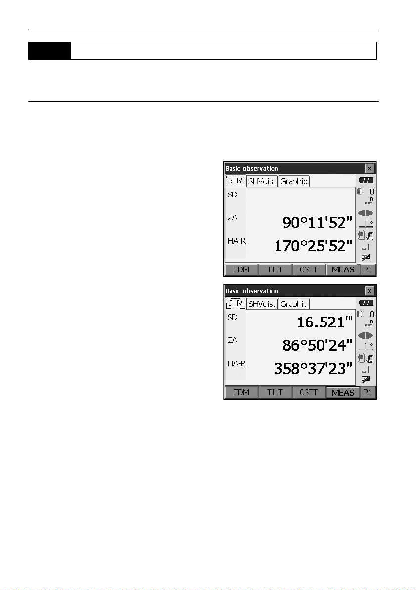
13.2 Distance and Angle Measurement
An angle can be measured at the same time as distance.
PROCEDURE
1. Face the OS in the direction of the target
Use the sighting collimator to aim the OS and
telescope toward the target.
"11. FOCUSSING AND TARGET SIGHTING"
2. Start measurement.
Press [MEAS] in the first page of Observation
mode to start measurement.
The measured distance data (SD), vertical angle
(ZA), and horizontal angle (HA-R) are displayed.
13. DISTANCE MEASUREMENT
3. Press [STOP] to quit distance measurement.
• If the single measurement mode is selected, measurement automatically stops after a single
measurement.
• During fine average measurement, the distance data is displayed as SD1, SD2,... to SD9. When the
designated number of measurements has been completed, the average value of the distance is
displayed in the "SDA" line.
• If the tracking measurement is conducted with the target type "N-Prism", the measured data for a
distance exceeding 250m is not displayed.
• The distance and angle that are most recently measured remain stored in the memory until the
power is off and can be displayed at any time by pressing [CALL].
Allocating [CALL]: "20.6 Allocating Key Functions"
58
Page 65

13. DISTANCE MEASUREMENT
13.3 Distance Measurement and Outputting the Data
The following explains distance measurement and the features used to output measurement data to
a computer or external devices.
"10. CONNECTING TO EXTERNAL DEVICES", Communication cables: "25. OPTIONAL
ACCESSORIES". Output format and command operations: "Communication manual"
PROCEDURE
1. Connect OS and external device.
2. Sight the target point.
3. Press [HVDOUT-T] or [HVDOUT-S] to measure
the distance and output the data to the external
device.
4. Press [STOP] to stop outputting data and return
to Observation Mode.
59
Page 66
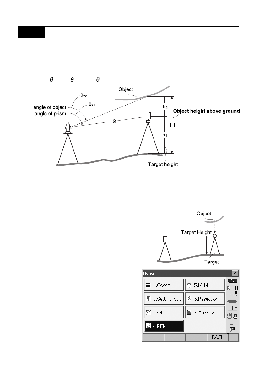
13. DISTANCE MEASUREMENT
Zenith
Zenith
13.4 REM Measurement
An REM measurement is a function used to measure the height to a point where a target cannot be
directly installed such as power lines, overhead cables and bridges, etc.
The height of the target is calculated using the following formula.
Ht = h
+ h
1
h2 = S sinz1 x cotz2 - S cos
• It is possible to allocate softkeys in measurement menus to suit various applications and the ways
that different operators handle the instrument.
2
z1
"20.6 Allocating Key Functions"
PROCEDURE
1. Set the target directly under or directly over the
object and measure the target height with a tape
measure etc.
Press [HT] and enter the target height.
2. Select "REM" in <Menu>.
60
Page 67
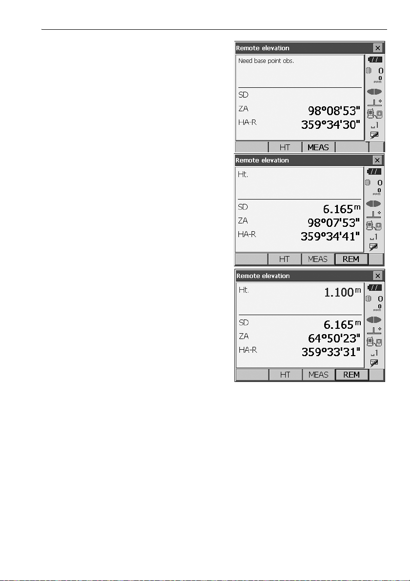
3. Sight the target and press [MEAS] to start
measurement. Press [STOP] to stop the
measurement.
The measured distance data, vertical angle and
horizontal angle are displayed.
4. Sight the object, then press [REM] to start REM
measurement is started. The height from the
ground to the object is displayed in "Ht.".
Press [STOP] to stop the measurement.
13. DISTANCE MEASUREMENT
• To re-observe the target, sight the target then
press [MEAS].
• To continue REM measurement, press [REM].
• When measurement data already exists, select
"REM" in <Menu> as in step 2 to proceed to step 4 and start REM measurement. Press [STOP] to
stop the measurement.
61
Page 68
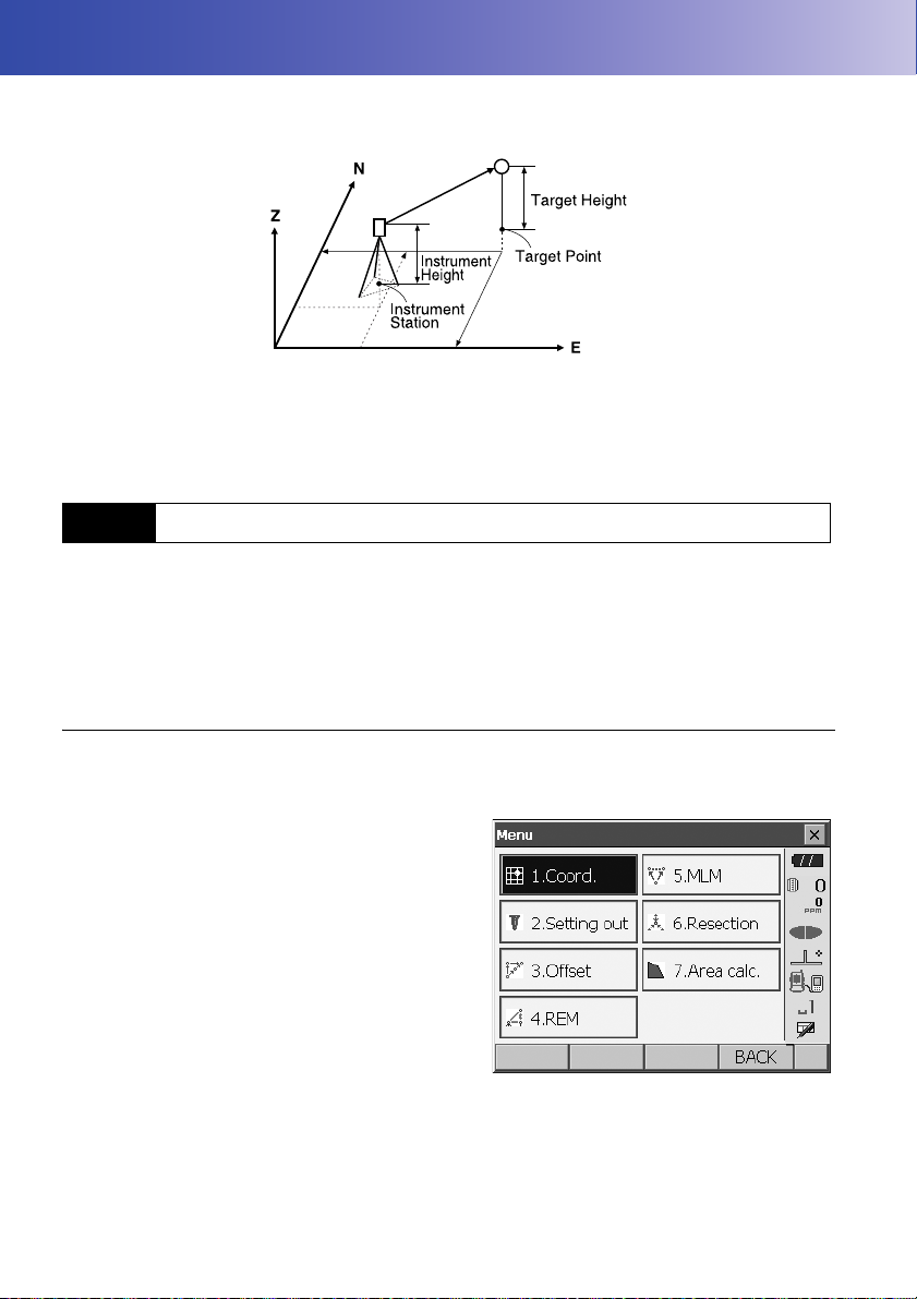
14.COORDINATE MEASUREMENT
By performing coordinate measurements it is possible to find the 3-dimensional coordinates of the
target based on station point coordinates, instrument height, target height, and azimuth angles of the
backsight station which are entered in advance.
• It is possible to allocate softkeys in measurement menus to suit various applications and the ways
that different operators handle the instrument.
"20.6 Allocating Key Functions"
14.1 Entering Instrument Station Data
Before performing coordinate measurement, enter instrument station coordinates and instrument
height.
• "Occupy" on the software represents instrument station.
PROCEDURE
1. First measure the instrument height with a tape
measure, etc.
2. Select "Coord." in <Menu>.
62
Page 69
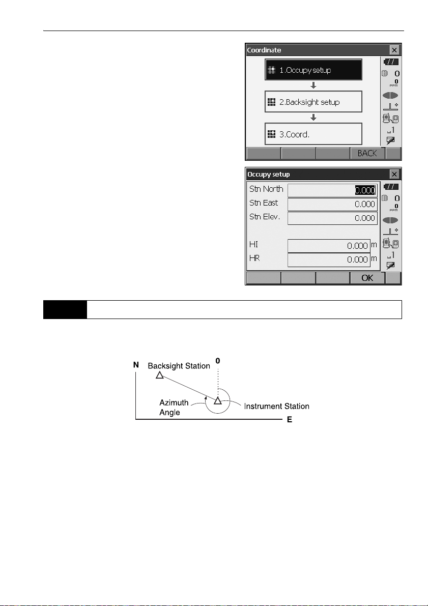
3. Select "Occupy setup" and enter instrument
station coordinates,instrument height (HI) and
target height (HR).
4. Press [OK] to set the input values. <Set H angle>
is displayed again.
14.2 Azimuth Angle Setting
14. COORDINATE MEASUREMENT
Based on the instrument station coordinates and backsight station coordinates which have already
been set, the azimuth angle of the backsight station is calculated.
63
Page 70
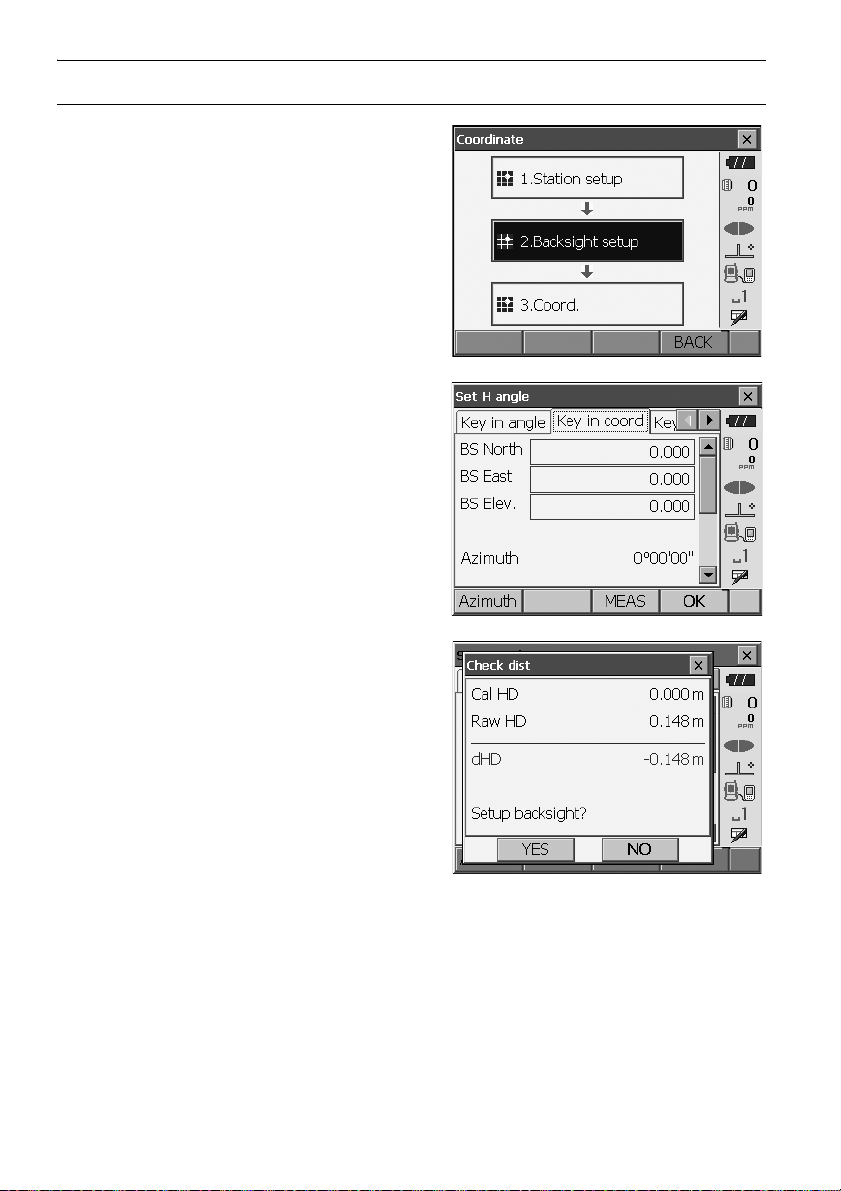
PROCEDURE Entering coordinates
1. Select "Backsight setup" in <Coordinate>. <Set
H angle> is displayed.
• <Set H angle> can also be displayed from the
screen in step 4 of "14.1 Entering Instrument
Station Data".
2. Select the "Key in coord" tab and enter the
backsight station coordinates.
14. COORDINATE MEASUREMENT
• When checking backsight distance, sight the
backsight station and press [MEAS]. Press
[STOP] to display the distance calculated from
coordinates, the measured distance, and the
difference between the two. Press [YES] to set
the azimuth angle and display <Coord.
measurement>.
• [Azimuth]: Switches horizontal angle setting
method.
"
Horizontal angle settings
3. Press [OK] to set the azimuth angle. <Coord.
measurement> is displayed.
"
64
Page 71
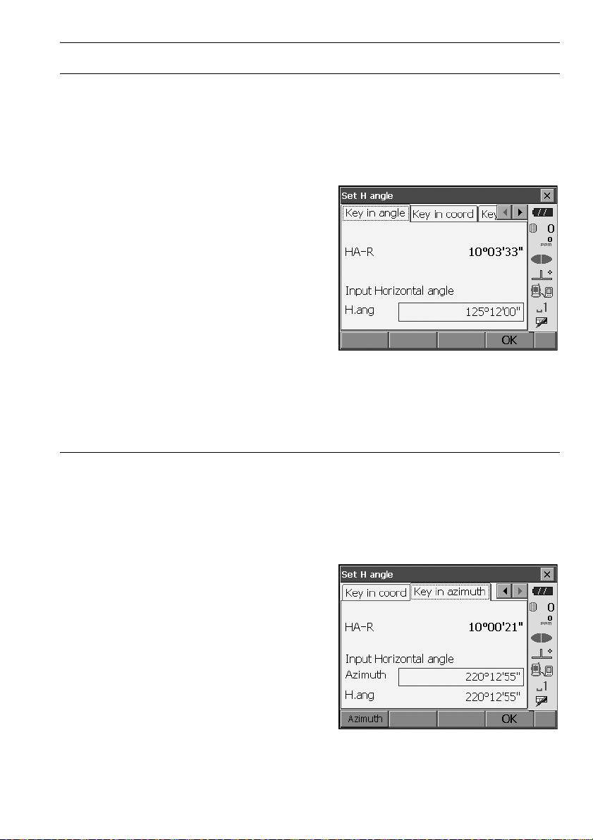
PROCEDURE Entering angle
1. Select "Backsight setup" in <Coordinate>. <Set
H angle> is displayed.
. <Set H angle> can also be displayed from the
screen in step 4 of "14.1 Entering Instrument
Station Data".
2. Select the "Key in angle" tab and enter the
desired angle in "H.ang".
3. Press [OK] to set the input values. <Coord.
measurement> is displayed.
14. COORDINATE MEASUREMENT
PROCEDURE Entering azimuth
1. Select "Backsight setup" in <Coordinate>. <Set
H angle> is displayed.
<Set H angle> can also be displayed from the
screen in step 4 of "14.1 Entering Instrument
Station Data".
2. Select the "Key in azimuth" tab and enter the
desired angle in "Azimuth".
• [Azimuth]: Switches horizontal angle setting
method.
"
Horizontal angle settings
"
65
Page 72
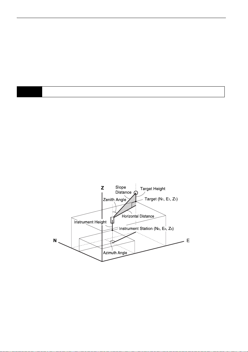
14. COORDINATE MEASUREMENT
3. Press [OK] to set the input values. <Coord.
measurement> is displayed.
Horizontal angle settings
Azimuth (set both horizontal and azimuth angles to the same value)/H.ang (input both horizontal
and azimuth angles)/None (input azimuth angle only)/0 SET (horizontal angle set to 0°)
14.3 3-D Coordinate Measurement
The coordinate values of the target can be found by measuring the target based on the settings of the
instrument station and backsight station.
The coordinate values of the target are calculated using the following formulae.
N1 Coordinate = N0 + S x sinZ x cosAz
E1 Coordinate = E0 + S x sinZ x sinAz
Z1 Coordinate = Z0 + S x cosZ + ih - th
N0: Station point N coordinate S: Slope distance ih: Instrument height
E0: Station point E coordinate Z: Zenith angle th: Target height
Z0: Station point Z coordinate Az: Direction angle
"Null" coordinates will not be included in calculations. "Null" is not the same as zero.
66
Page 73

PROCEDURE
1. Sight the target at the target point.
2. Select "Coord." in <Coordinate>.
Press [MEAS] to start measurement. Press
[STOP] to stop the measurement. The
coordinates of the target point are displayed.
Select the "Graphic" tab to display coordinates on
a graph.
14. COORDINATE MEASUREMENT
3. Sight the next target and press [MEAS] to begin
measurement. Continue until all targets have
been measured.
4. When coordinate measurement is completed,
press {ESC} or tap the cross in the top-right
corner to return to <Coordinate>.
67
Page 74

15.RESECTION MEASUREMENT
Resection is used to determine the coordinates of an instrument station by performing multiple
measurements of points whose coordinate values are known. Registered coordinate data can be
recalled and set as known point data. Residual of each point can be checked, if necessary.
Entry Output
Coordinates of
known point
Observed
horizontal angle
Observed vertical
angle
Observed distance : Di
: (Ni, Ei, Zi) Station point coordinates : (N0,E0, Z0)
:Hi
:Vi
• Between 2 and 10 known points can be measured by distance measurement, and between 3 and
10 known points by angle measurement.
• The more known points there are and the more points there are whose distance can be measured,
the higher the precision of the coordinate value calculation.
• It is possible to allocate softkeys in measurement menus to suit various applications and the ways
that different operators handle the instrument.
"20.6 Allocating Key Functions"
68
Page 75

15. RESECTION MEASUREMENT
15.1 Coordinate Resection Measurement
N, E, Z of an instrument station is determined by the measurement.
PROCEDURE
1. Select "Resection" in <Menu>.
2. Select "NEZ" to display <Resection/Known
point>.
3. Input the known point.
After setting the coordinates and target height for
the first known point press [NEXT] to move to the
second point.
•Press
[PREV] to return to settings for the
previous point.
When all required known points have been set,
press [OK].
69
Page 76

4. Sight the first known point and press [MEAS] to
begin measurement.
The measurement results are displayed on the
screen.
• When [ANGLE] has been selected, the distance
cannot be displayed.
5. Press [YES] to use the measurement results of
the first known point.
• You can also input target height here.
•Press [NO] to return to the screen in step 4 and
perform measurement again.
6. Repeat procedures 4 to 5 in the same way from
subsequent points.
When the minimum quantity of observation data
required for the calculation is present, [CALC] is
displayed.
15. RESECTION MEASUREMENT
7. Press
[CALC] or [YES] to automatically start
calculations after observations of all known points
are completed.
• Instrument station coordinates, station elevation,
and standard deviation, which describes the
measurement accuracy, are displayed.
70
Page 77

Standard deviation for the northing, easting and
2nd
elevation coordinates of each point are displayed
in the "Detail" tab.
8. If there are problems with the results of a point,
align the cursor with that point and press [OMIT].
“OMIT” is displayed to the right of the point.
Repeat for all results that include problems.
9. Press [RE_CALC] to perform calculation again
without the point designated in step 8. The result
is displayed.
If there are no problems with the result, go to step
10.
If problems with the result occur again, perform
the resection measurement from step 4.
•
Press
[RE OBS]
designated in step 8.
If no points are designated in step 8, all the
points or only the final point can be observed
again.
to measure the point
15. RESECTION MEASUREMENT
71
Page 78

• Press [ADD] in the second page when there is a
known point that has not been observed or when
a new known point is added.
10.
Press [OK] in <Resection/result> to display
<Resection/Set h angle>.
15. RESECTION MEASUREMENT
[YES]
11. Select an angle mode and press
azimuth angle of the first known point as the
backsight point and return to <Resection/Menu>.
12. Press [NO] to return to <Resection/Menu>
without setting the azimuth angle.
to set the
Horizontal angle settings
H (set horizontal angle to measured value)/H=Az (set horizontal angle to the same value as
azimuth angle)/Az (set azimuth angle only)
• It is also possible to perform resection measurement by pressing [RESEC] in the third page of
Observation mode.
72
Page 79

15. RESECTION MEASUREMENT
15.2 Height Resection Measurement
Only Z (height) of an instrument station is determined by the measurement.
• Known points must be measured by distance measurement only.
• Between 1 and 10 known points can be measured.
PROCEDURE
1. Select "Resection" in <Menu>.
2. Select "Elevation" to display <Resection/Known
point>.
3. Input the known point.
After setting the elevation and target height for the
first known point press [NEXT] to move to the
second point.
• Press
[PREV] to return to settings for the
previous point.
When all required known points have been set,
press [OK].
73
Page 80
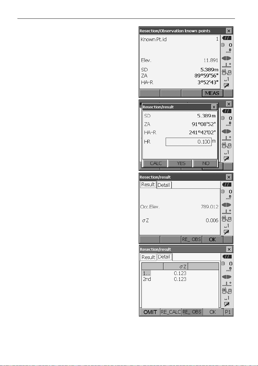
4. Sight the first known point and press [MEAS] to
begin measurement.
The measurement results are displayed on the
screen.
5. If measuring two or more known points, repeat
procedures 4 in the same way from the second
point.
6. Press [CALC] or [YES] to automatically start
calculations after observations of all known points
are completed.
• Instrument station elevation and standard
deviation, which describes the measurement
accuracy, are displayed in the "Result" tab.
15. RESECTION MEASUREMENT
Standard deviation values for each point are
displayed in the "Detail" tab.
74
Page 81
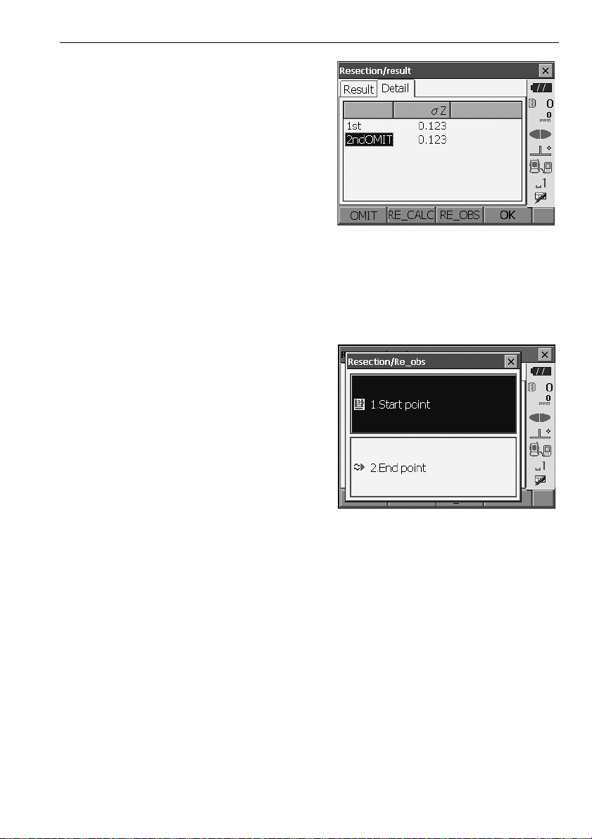
7. If there are problems with the results of a point,
align the cursor with that point and press [OMIT].
“OMIT” is displayed to the right of the point.
Repeat for all results that include problems.
8. Press [RE CALC] to perform calculation again
without the point designated in step 7 The result
is displayed.
If there are no problems with the result, go to step
9.
If problems with the result occur again, perform
the resection measurement from step 4.
•Press [RE_OBS] to measure the point
designated in step 7.
If no points are designated in step 7, all the
points or only the final point can be observed
again.
15. RESECTION MEASUREMENT
•Press [ADD] in the second page when there is a
known point that has not been observed or when
a new known point is added.
9. Press [OK] to finish resection measurement and
return to <Resection/Menu>. Only Z (elevation) of
the instrument station coordinate is set. N and E
values are not overwritten.
75
Page 82
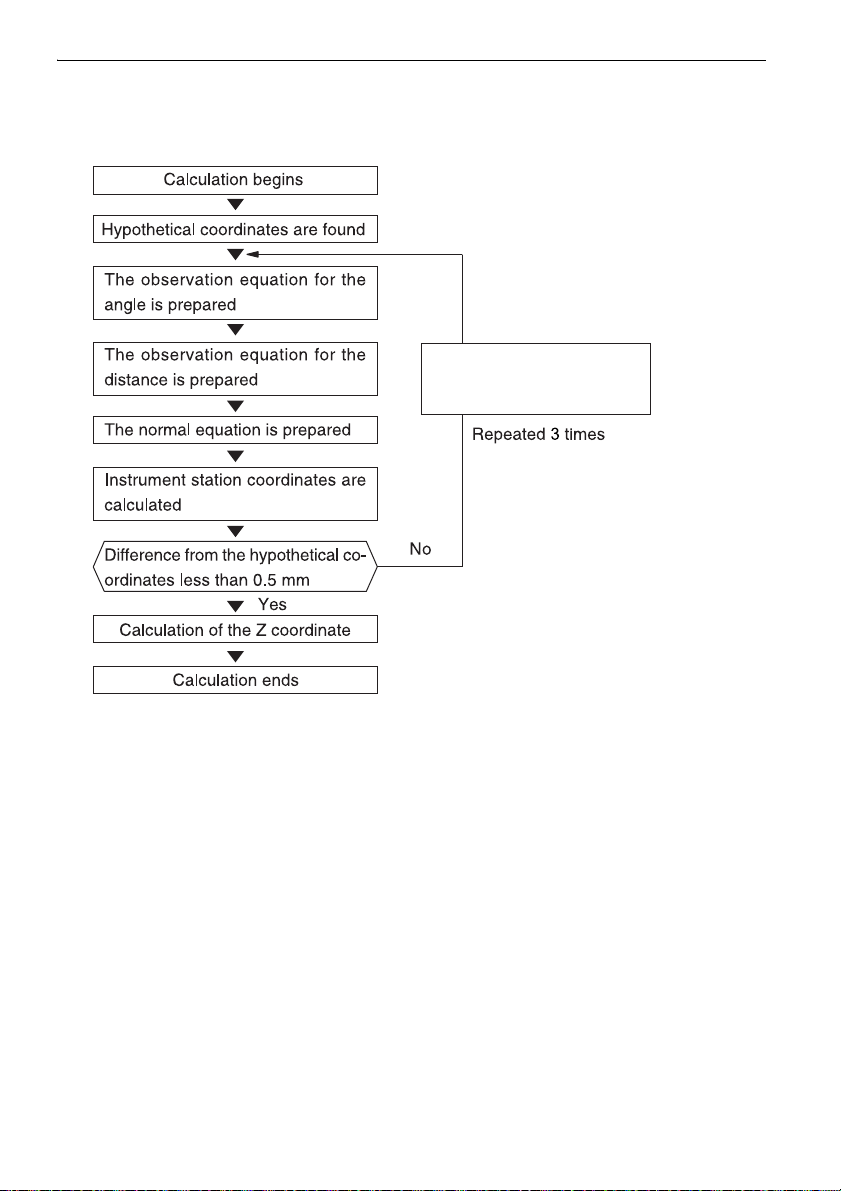
15. RESECTION MEASUREMENT
Calculated instrument
station coordinates set
as hypothetical coordinates
Resection calculation process
The NE coordinates are found using angle and distance observation equations, and the
instrument station coordinates are found using the method of least squares. The Z coordinate
is found by treating the average value as the instrument station coordinates.
76
Page 83
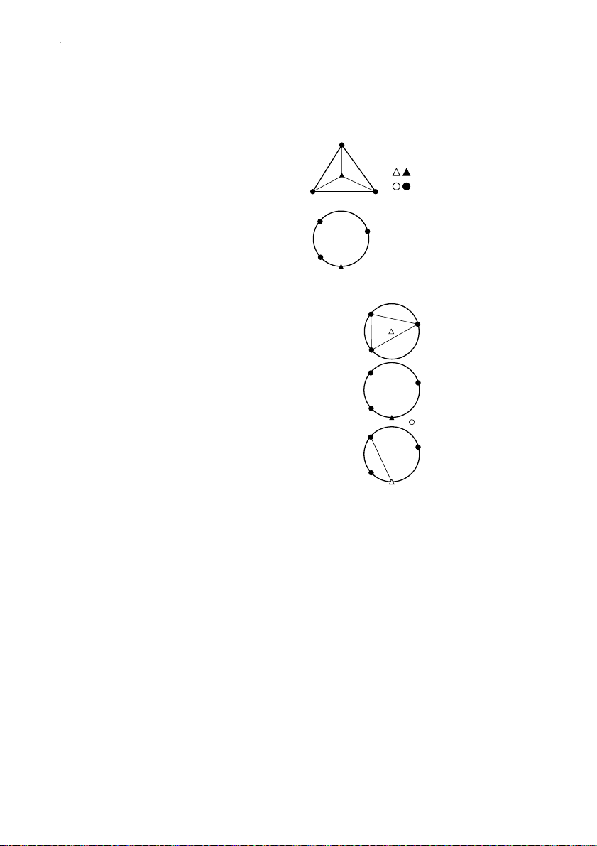
15. RESECTION MEASUREMENT
: Unknown point
: Known point
Precaution when performing resection
In some cases it is impossible to calculate the coordinates of an unknown point (instrument
station) if the unknown point and three or more known points are arranged on the edge of a
single circle.
An arrangement such as that shown below is desirable.
It is sometimes impossible to perform a correct calculation in a case such as the one below.
When they are on the edge of a single circle, take one of the following measures.
(1) Move the instrument station as close as possible
to the center of the triangle.
(2) Observe one more known point which is not on the
circle.
(3) Perform a distance measurement on at least one
of the three points.
• In some cases it is impossible to calculate the coordinates of the instrument station if the included
angle between the known points is too small. It is difficult to imagine that the longer the distance
between the instrument station and the known points, the narrower the included angle between the
known points. Be careful because the points can easily be aligned on the edge of a single circle.
77
Page 84

16.SETTING-OUT MEASUREMENT
Setting-out measurement is used to set out the required point.
The difference between the previously input data to the instrument (the setting-out data) and the
measured value can be displayed by measuring the horizontal angle, distance or coordinates of the
sighted point.
The horizontal angle difference distance difference, and coordinate difference are calculated and
displayed using the following formulae.
Horizontal difference
Displayed value (angle) = Horizontal angle of setting-out data - measured horizontal angle
Displayed value (distance) = measured horizontal distance x tan (horizontal angle of setting out data
Slope distance difference
Displayed value (slope distance) * = measured slope distance - slope distance setting-out data
* Horizontal distance or height difference can be input in the above formula.
Coordinate difference
Displayed value (coordinates)* measured N setting-out coordinates - N coordinates of setting-out data
* E or Z coordinates can be input in the above formula
Height difference (REM setting out measurement)
Displayed value (height) = measured REM data - REM data of setting out data
• Setting out data can be input in various modes: slope distance, horizontal distance, height
difference, coordinates and REM measurement.
• It is possible to allocate softkeys in the Setting-out measurement menu to suit various applications
and the ways that different operators handle the instrument.
"20.6 Allocating Key Functions"
- measured horizontal angle)
16.1 Using the Guide Light
When the guide light is set to ON, the flashing speed of the light indicates the status of the OS and
can be known when the user is located at a distance from the instrument. Also, the flashing colors
relative to the target indicate the direction of the instrument and allow the user to reposition the target.
Turning the Guide light ON/OFF: "5.1 Basic Key Operation"
• The pattern of the guide light can be changed.
"20.2 Instrument Configuration"
78
Page 85
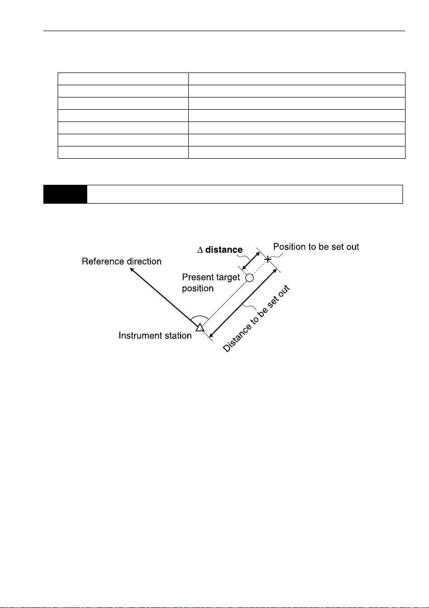
Guide light status and meaning
16. SETTING-OUT MEASUREMENT
Indication for positioning target during setting-out measurement
Increased flashing speed (From position of poleman) Move target toward OS
Decreased flashing speed (From position of poleman) Move target away from OS
Fast flashing Target is at correct distance
Red (From position of poleman) Move target left
Green (From position of poleman) Move target right
Red and Green Target is at correct horizontal position
Light status Meaning
16.2 Distance Setting-out Measurement
The point is to be found based on the horizontal angle from the reference direction and the distance
from the instrument station.
79
Page 86
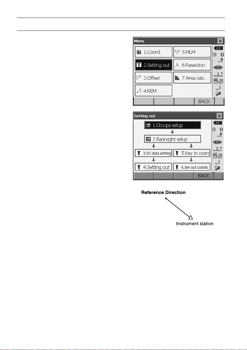
PROCEDURE
1. Select "Setting out" in <Menu> to display <Setting
out>.
16. SETTING-OUT MEASUREMENT
2. Select "Occupy setup" to display <Occupy
setup>. Enter data for the instrument station and
press [OK] to move to Backsight setup.
"14.1 Entering Instrument Station Data"
3. Set the azimuth angle for the backsight station.
Press [OK] to return to <Setting out>.
"14.2 Azimuth Angle Setting"
80
Page 87
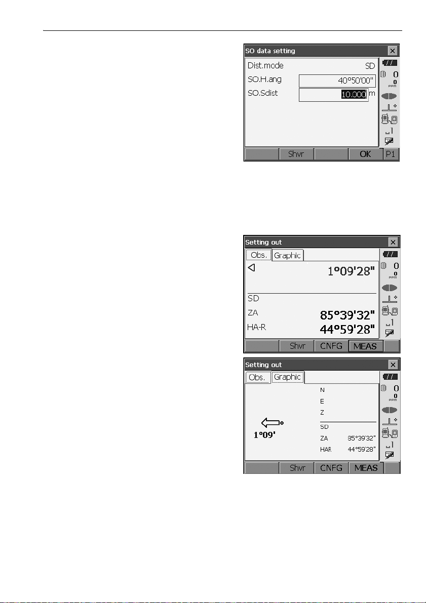
4. Select "SO data setting" In <Setting out> to
display <SO data setting>. In the distance mode
that conforms to your measurement
requirements, enter the included angle between
the reference point and the setting-out point in
"SO.H.ang", and the distance (slope distance,
horizontal distance or height difference) from the
instrument station to the position to be set out in
"SO.Sdist".
• Each time [Shvr] is pressed, the distance mode
changes from "SD" (slope distance), "HD"
(horizontal distance), "VD" (height difference),
and "Ht." (REM).
•Press [COORD] in the second page and input
coordinates in <Key in coord>. The angle and
distance from these coordinates to the position
to be set out will be calculated.
5. Enter values and press [OK] to display the
screen at right.
16. SETTING-OUT MEASUREMENT
81
Page 88
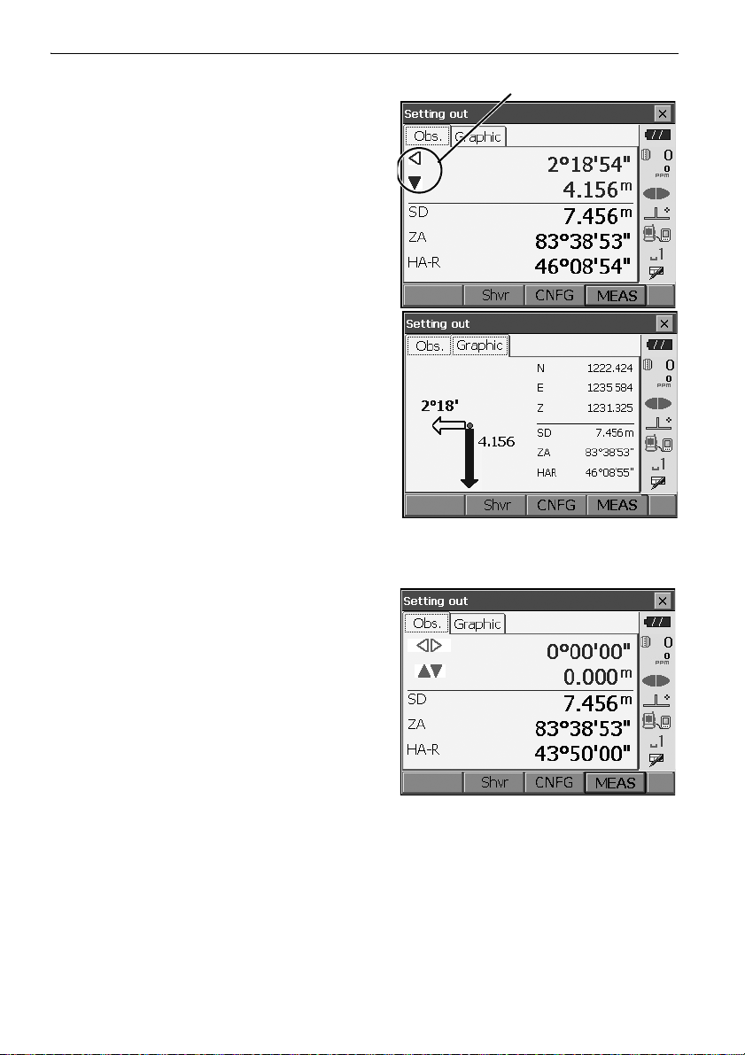
6. Position the target on the line of sight and press
Arrows indicate direction to move
[MEAS] to begin distance measurement.
The distance and direction to move the target until
the setting out point is located is displayed on the
OS. The sighting point measurement results
(currently installed position of the target) are
displayed.
• Movement indicator (Red indicates that target
position is correct)
: (Viewed from OS) Move target to the left
: (Viewed from OS) Move target to the right
: Target position is correct
: (Viewed from OS) Move target closer
: (Viewed from OS) Move target away
: (Viewed from OS) Target position is correct
: Move target upward
: Move target downward
: Target position is correct
• Each time [Shvr] is pressed, the distance mode
changes from horizontal distance, height
difference, slope distance (REM), and (slope
distance).
• Press [CNFG] to set setting out accuracy. When
the position of the target is within this range both
arrows will be displayed to indicate that the
target position is correct.
7. Move the target until the distance to the settingout point reads 0m. When the target is moved
within the allowed range, all distance and position
arrows are displayed.
16. SETTING-OUT MEASUREMENT
82
Page 89
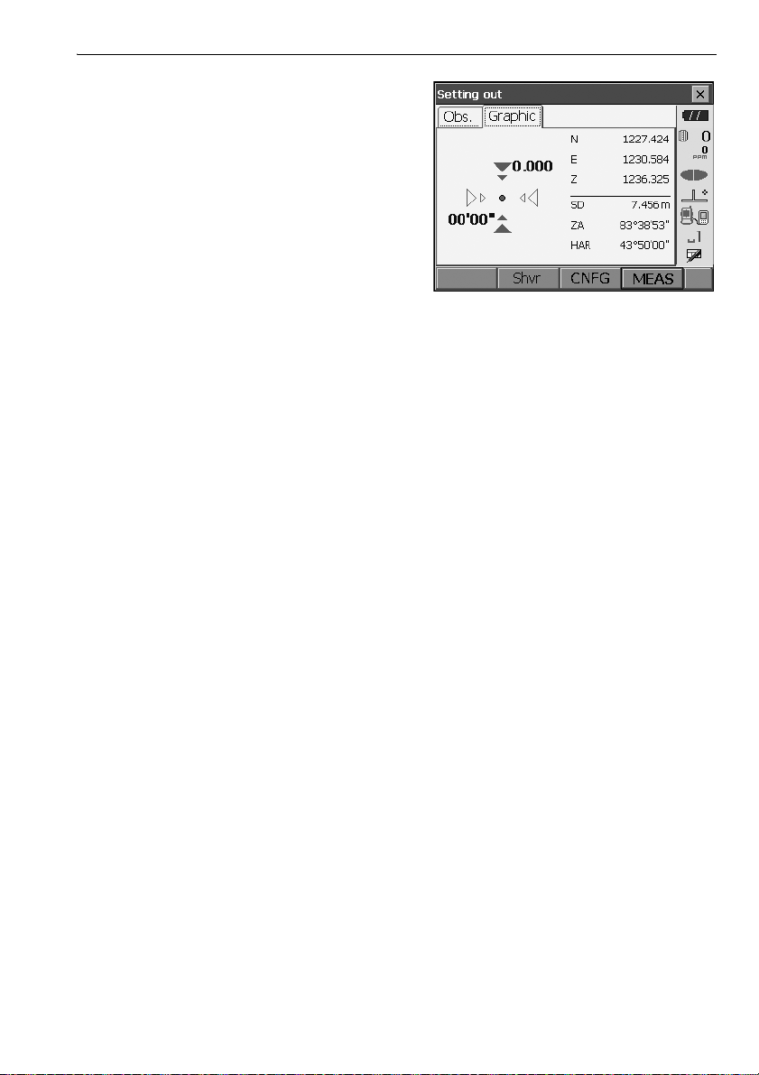
8. Press {ESC} to return to <Setting out>. Set the
next setting out point to continue setting out
measurement.
16. SETTING-OUT MEASUREMENT
83
Page 90

16. SETTING-OUT MEASUREMENT
16.3 Coordinates Setting-out Measurement
After setting the coordinates for the point to be set out, the OS calculates the setting-out horizontal
angle and horizontal distance. By selecting the horizontal angle and then the horizontal distance
setting-out functions, the required coordinate location can be set out.
• Previously recorded setting-out points can be placed in order. Up to 50 points can be recorded.
•To find the Z coordinate, attach the target to a pole etc. with the same target height.
PROCEDURE
1. Select "Setting out" in <Menu> to display <Setting
out>.
2. Select "Occupy setup" to display <Occupy
setup>. If necessary, enter data for Backsight
setup.
"16.2 Distance Setting-out Measurement"
steps 2 to 3
84
Page 91
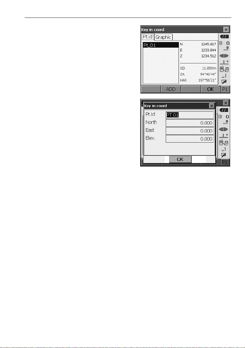
16. SETTING-OUT MEASUREMENT
Select "Key in coord" in <Setting out>.
3.
the setting-out points (includes setting-out points
you will measure from now).
Press [ADD] to record new data.
•Press [DEL] in the second page to delete the
selected setting out point.
•Press [DELALL] in the second page to delete all
setting out points.
4. Select a setting-out point in the first screen of step
3 and press [OK] to display <Set out Coords>.
Record all
85
Page 92

5. Position the target on the line of sight and press
Height difference direction
Position of poleman
[MEAS] to begin distance measurement.
The distance and direction to move the target until
the setting out point is located is displayed on the
OS. The sighting point measurement results
(currently installed position of the target) are
displayed.
• Switch between the tabs to display different sets
of information.
The Graph 1 tab shows the current position of
the mirror and the direction to the setting out
point from this position.
The Graph 2 tab shows the position of the setting
out point (square) and the current location of the
mirror (circle).
16. SETTING-OUT MEASUREMENT
Move the target to find the correct distance (0 is
displayed) to the setting out point.
Movement indicators: "16.2 Distance Setting-
out Measurement" step 6
86
Page 93

6. Press [OK] to return to <Key in coord>. Set the
next setting out point to continue setting out
measurement.
16. SETTING-OUT MEASUREMENT
16.4 REM Setting-out Measurement
To find a point where a target cannot be directly installed, perform REM setting-out measurement.
"13.4 REM Measurement"
PROCEDURE
1. Install a target directly below or directly above the
point to be found. Then use a measuring tape etc.
to measure the target height (height from the
survey point to the target).
2. Select "Occupy setup" in <Setting out> to display
<Occupy setup>. If necessary, enter data for
Backsight setup.
"16.2 Distance Setting-out Measurement"
steps 2 to 3
87
Page 94

3. Select "SO data setting" In <Setting out> to
display <SO data setting>. Press [Shvr] until the
distance input mode is "SO.Height.". Input height
from the surveying point to the position to be set
out in "SO.Height". If necessary, input the angle to
the point to be set out.
4. Enter values and press [OK] in step 3 to display
the screen at right.
5. Sight the target and press [MEAS]. Measurement
begins and the measurement results are
displayed.
16. SETTING-OUT MEASUREMENT
88
Page 95

6. Press [REM] to start REM measurement.
Arrows indicate direction to move
The distance (height difference) and direction to
move the target until the sighting point and setting
out point are located is displayed on the OS.
Press [STOP] to stop measuring.
Find the setting-out point by moving the telescope
until the distance to the setting-out point reads 0m.
• Movement indicator (Red indicates that target
position is correct)
: Move the telescope near the zenith
: Move the telescope near the nadir
: Telescope direction is correct
For details of other movement indicators:
"16.2 Distance Setting-out Measurement"
step 6
•Press [CNFG] to set setting out accuracy. When
the position of the target is within this range both
arrows will be displayed to indicate that the
target position is correct.
16. SETTING-OUT MEASUREMENT
7. Press {ESC} to return to <SO data setting>.
89
Page 96
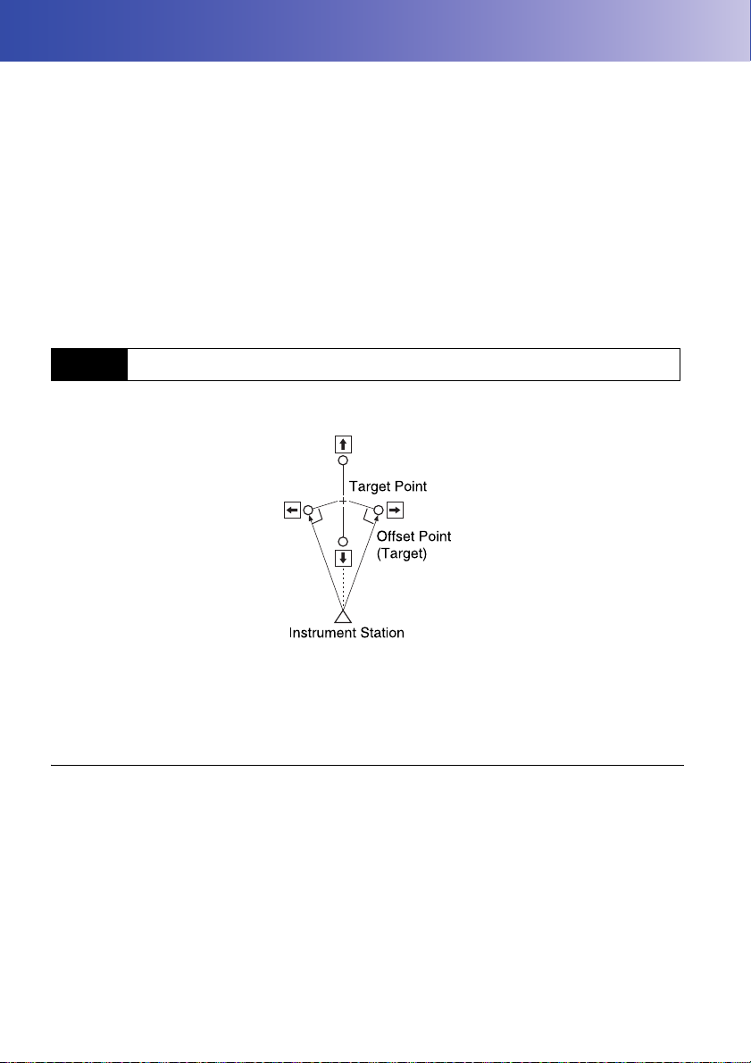
17.OFFSET MEASUREMENT
Offset measurements are performed in order to find a point where a target cannot be installed directly
or to find the distance and angle to a point which cannot be sighted.
• It is possible to find the distance and angle to a point you wish to measure (target point) by installing
the target at a location (offset point) a little distance from the target point and measuring the distance
and angle from the survey point to the offset point.
• The target point can be found in the three ways explained in this chapter.
• The instrument station and backsight must be set before the coordinates of an offset point can be
found. Station and backsight setup can be performed in the Offset menu.
Occupy setup: "14.1 Entering Instrument Station Data", Backsight setup: "14.2 Azimuth Angle
Setting" .
• It is possible to allocate softkeys in measurement menus to suit various applications and the ways
that different operators handle the instrument.
"20.6 Allocating Key Functions"
17.1 Single-distance Offset Measurement
Finding it by entering the horizontal distance from the target point to the offset point.
• When the offset point is positioned to the left or right of the target point, make sure the angle formed
by lines connecting the offset point to the target point and to the instrument station is almost 90°.
• When the offset point is positioned in front of or behind the target point, install the offset point on a
line linking the instrument station with the target point.
PROCEDURE
1. Set the offset point close to the target point and
measure the distance between them, then set up
a prism on the offset point.
90
Page 97
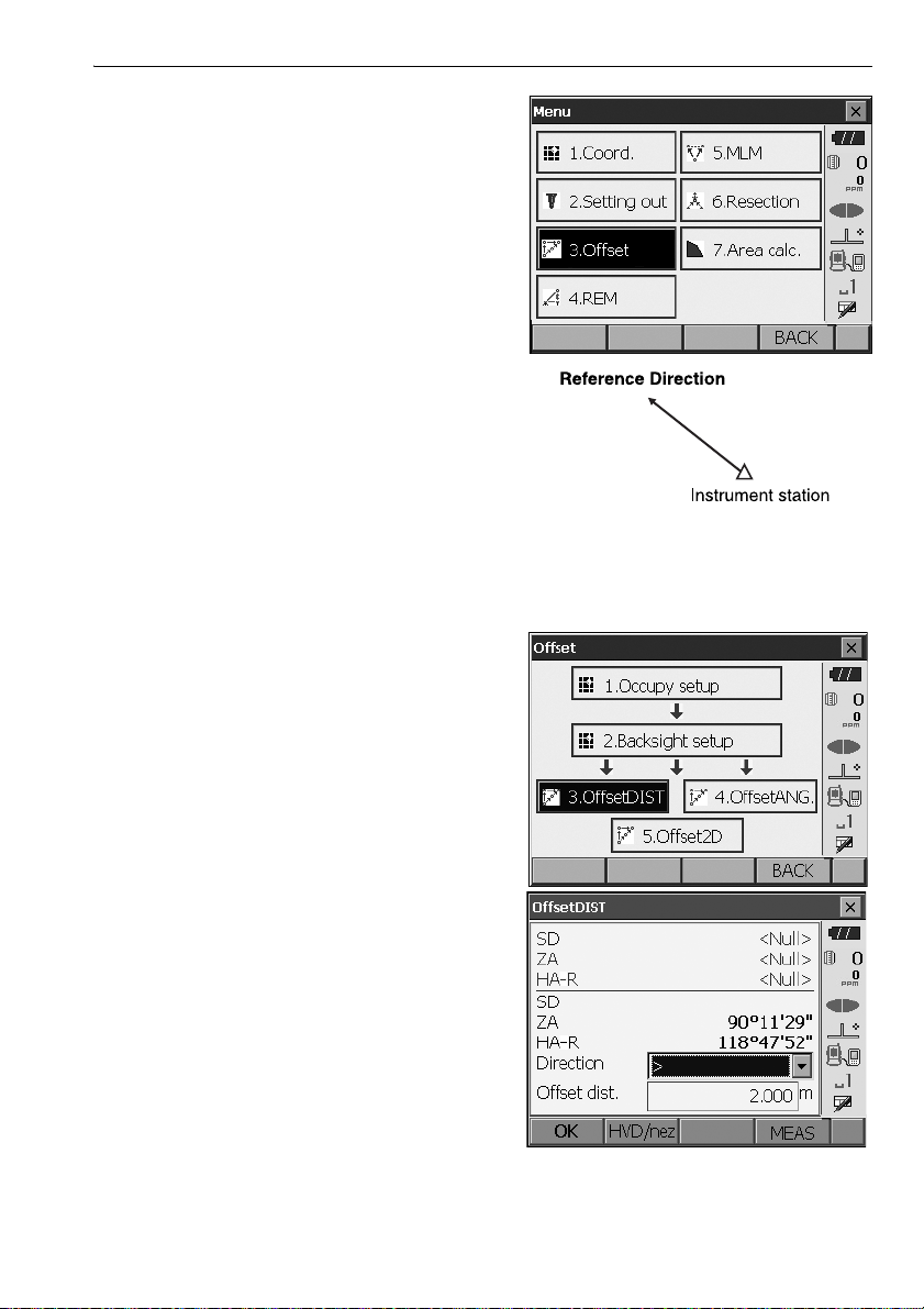
2. Select "Offset" in <Menu> to display .
3. Select "Occupy setup" to display <Occupy
setup>. Enter data for the instrument station and
press [OK] to move to Backsight setup.
"14.1 Entering Instrument Station Data"
4. Set the azimuth angle for the backsight station.
Press [OK] to return to <Offset>.
"14.2 Azimuth Angle Setting"
5. Select “OffsetDIST”.
Input the following items.
(1) Direction of the offset point.
(2) Horizontal distance from the target point to
the offset point.
17. OFFSET MEASUREMENT
• Direction of offset point
← : On the left of the target point.
→ : On the right of the target point.
↓ : Closer than the target point.
↑ : Beyond the target point.
91
Page 98
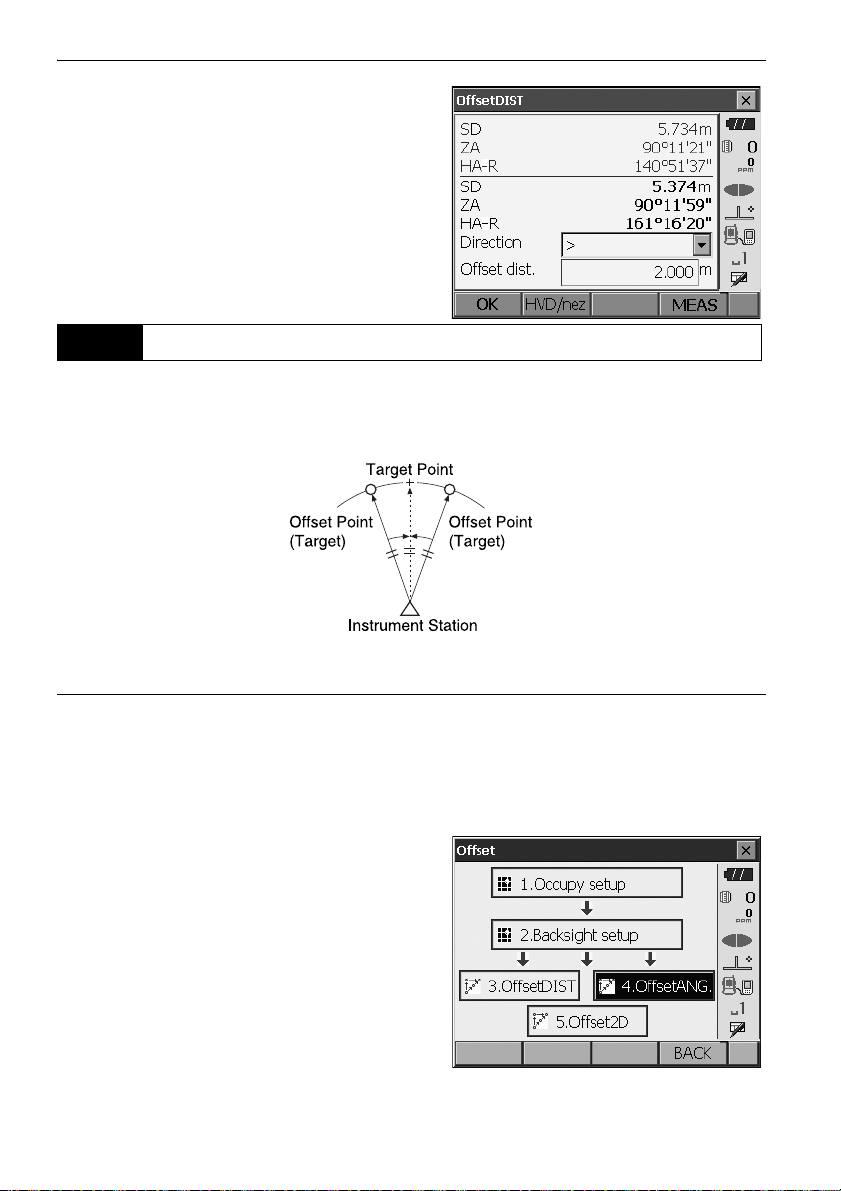
17. OFFSET MEASUREMENT
6. Sight the offset point and press [MEAS] in the
screen of step 5 to start measurement.
Press [STOP] to stop the measurement.
The measurement results are displayed.
•Press [HVD/nez] to switch results for the target
point between distance/angle values and
coordinate/elevation values.
17.2 Angle Offset Measurement
Sighting the direction of the target point to find it from the included angle.
Install offset points for the target point on the right and left sides of and as close as possible to the
target point and measure the distance to the offset points and the horizontal angle of the target point.
PROCEDURE
1. Set the offset points close to the target point
(making sure the distance from the instrument
station to the target point and the height of the
offset points and the target point are the same),
then use the offset points as the target.
2. Select "Offset" in <Menu> to display <Offset>.
Select "OffsetANG.".
92
Page 99
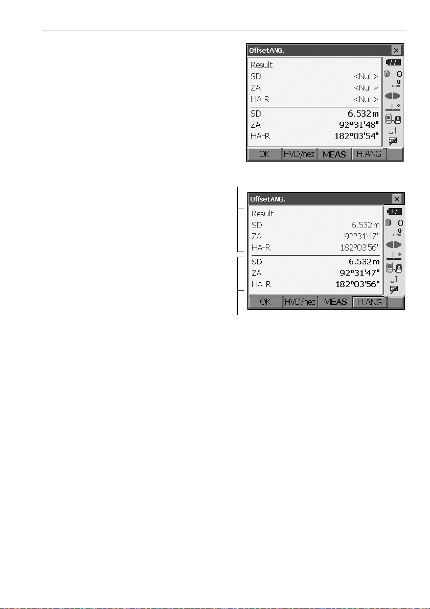
3. Sight the offset point and press [MEAS] to start
Results for offset point
Results for target point
measurement.
Press [STOP] to stop the measurement.
4. Sight the target point and press [H.ANG].
•Press [HVD/nez] to switch results for the
target point between distance/angle values
and coordinate/elevation values.
17. OFFSET MEASUREMENT
5. Press [OK] in the screen in step 4 to return to
<Offset>.
93
Page 100
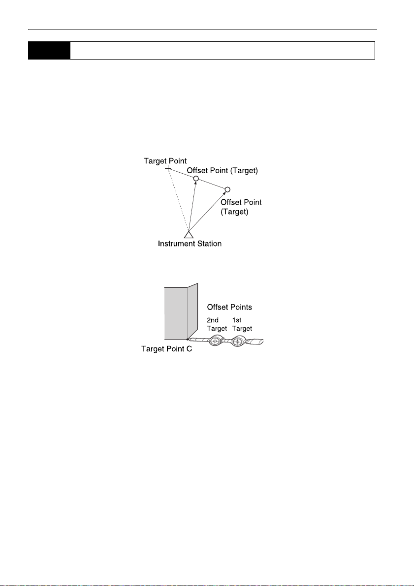
17. OFFSET MEASUREMENT
17.3 Two-distance Offset Measurement
By measuring the distances between the target point and the two offset points.
Install two offset points (1st target and 2nd target) on a straight line from the target point, observe the
1st target and 2nd target, then enter the distance between the 2nd target and the target point to find
the target point.
• It is possible to make this measurement easily using the optional equipment: the 2-point target
(2RT500-K). When using this 2-point target, be sure to set prism constant to 0.
"25. OPTIONAL ACCESSORIES"
How to use 2-point target (2RT500-K)
• Install the 2-point target with its tip at the target point.
• Face the targets toward the instrument.
• Measure the distance from the target point to the 2nd target.
• Set the prism constant to 0mm.
94
 Loading...