

Page 1
INSTRUCTION MANUAL
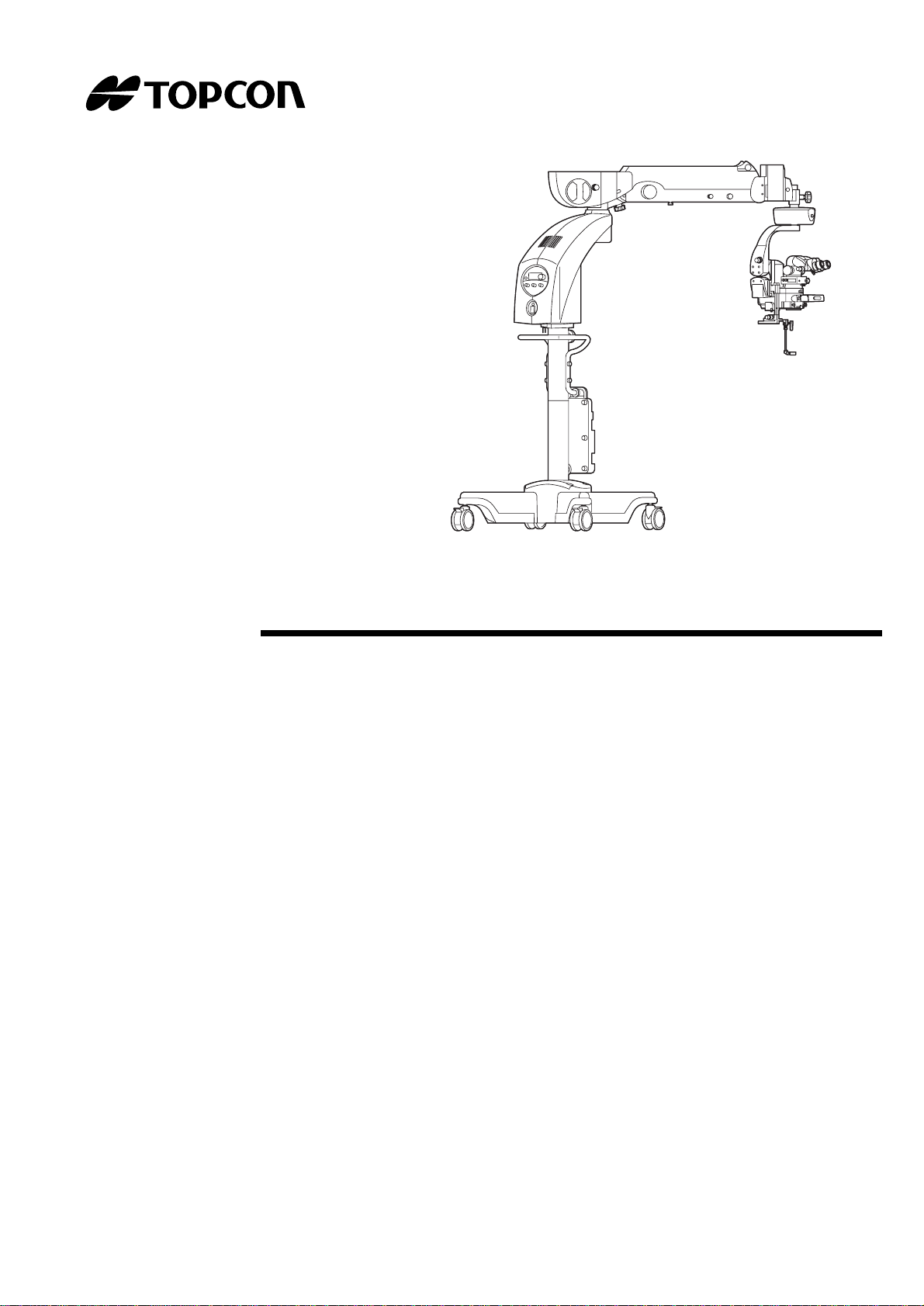
OPERATION MICROSCOPE
OMS-800
Page 2

INTRODUCTION
Thank you for purchasing the TOPCON OMS-800 Operation Microscope.
This product is an operation microscope for operations, treatment or observation.
This product is classified in five types according to the difference in the combination of the
microscope unit with the base unit. Each of five types is cla ssified int o two dif ferent types : one
type is equipped with a beam splitter of the fixed spectral ratio and the other with a
changeable beam splitter which can alternate two spectral ratios to each other.
• OFFISS : The microscope unit with the front lens is combined with the inverter and the
base unit with the electromagnetic lock and the rou gh focusing unit.
• OFFISS Lite : The microscope unit with the front lens is combined with the inverter and the
base unit with the electromagnetic lock and without the rough focusing unit.
• Pro : The microscope unit without the front lens is combined with the base unit
with the electromagnetic lock and the rough focusi ng unit.
• Pro Lite : The microscope unit without the front lens is combined with the base unit
with the electromagnetic lock and without the rough focusing unit.
• Standard : The microscope unit without the front lens is combined with the base unit
without the electromagnetic lock and the rough focusing unit.
This product has the following features.
• OFFISS* is mounted to greatly enhan ce the glass body operation. (Only i n OFFISS, OFFISS Lite.)
• Compact base and long arm provide a comfortable and extensive operation area.
• Electromagnetic lock is used to set it correctly at the required position. (Only in OFFISS,
OFFISS Lite, Pro and Pro Lite.)
• The 45°~90° variable eyepiece lens is used to set the optimum operation position.
This Instruction Manual describes the TOPCON OMS-800 Operation Microscope, and
includes outline, operations, troubleshooting, maintenance and cleaning.
To get the best use from the instrument, read "DISPLAY FOR SAFE USE" and "SAFETY
CAUTIONS". Keep this manual at hand for future reference.
[Warning]
Before using this instrument, make sure tha t th e components are set and fixed securely .
[Falling components may cause injury or death.]
Before using this instrum ent, adjust the balance of the 2nd arm.
[The microscope may move up and down suddenly, leading to injury.]
When using the coaxial illumination in the ophthalmic operation, use the minimum
illumination sufficient for operation.
[Exposing the patient’s retina to excessive light may lead to retinal trouble.]
To reduce or prevent retinal trouble, use the front lens within 40 minutes (illumination
light intensity display: 0.7)/within 70 minutes (illumination light intensity display: 0.4).
[Using the front lens for a long time may lead to retinal trouble. ]
When using the front lens, make sure it does not come into contact with the patient.
[Injury may result from a unit coming into contact with a patient.]
*OFFISS is an abbreviation of Optical Fiber Free Intr avitreal Surgery System.
1
Page 3

CAUTIONS FOR USE
Basic caution
Before using, sterilize the sterilized cap, the front lens unit, the peripheral observation prism and the
anterior eye section observation lens.
Disposal
Dispose of the instrument according to the local government's laws regarding disposal and recycling.
ENVIRONMENT FOR USE
Temperature : 10°C~40°C
Humidity : 30%~75% (without dew condensation)
Air pressure : 700~1060hPa
STORAGE, PERIOD OF USE AND OTHERS
1. Environmental conditions
Temperature: 10°C~40°C
Humidity: 30%~75% (without dew condensation)
Air pressure: 700~1060hPa
2. Storage requirements.
(1)Do not splash this instrument with water.
(2)Make sure this instrument is stored under safe conditions with regard to air pressure,
temperature, humidity, ventilation, sunlight or salty/s ulfurous air.
(3)T his ins trument must be kept st able, without i nclinati on, vibrat ion or shock ( not only in storage,
but also during transportation).
(4) Do not store this instrument in a location where chemicals are stored or gas is generated.
3. Limit of period of use
8 years following delivery, only if regular inspection and maintenance have been carried out
(according to self-certification [Topcon's data]).
2
Page 4

POINTS FOR INSPECTION AND MAINTENANCE
1. After using this instrument, immediately remove any remaining blood, body fluids, tissues, etc.,
and clean and sterilize it.
2. Check the instrument and its pa rts periodically.
3. When using the instrument again after a long time in storage, make sure beforehand that it is
operating safely and normally.
4. Do not soil the objective lens and the eyepiece lens with fingerprints or dust.
5. Cover the instrument when not in use.
6. If the objective lens or the eyepiece lens is soiled, clean it according to the instructions under
"CLEANING THE OBJECTIVE LENS / THE EYEPIECE LENS" in the instruction manual.
The terms below apply to this manual as follows.
Term Application
OFFISS : Applies to OFFISS only.
OFFISS Lite : Applies to OFFISS Lite only.
Pro : Applies to Pro only.
Pro Lite : Applies to Pro Lite only.
Standard : Applies to Standard only.
OFFISS, OFFISS Lite : Applies to OFFISS and OFFISS Lite.
OFFISS, OFFISS Lite, Pro, Pro Lite : Applies to OFFISS, OFFISS Lite, Pro and Pro Lite.
OFFISS, Pro : Applies to OFFISS and Pro.
OFFISS Lite, Pro Lite, Standard : Applies to OFFISS Lite, Pro Lite and Standard.
Pro, Pro Lite :Applies to Pro and Pro Lite.
Pro, Pro Lite, Standard : Applies to Pro,Pro Lite and Standard.
Common : Applies to OFFISS, OFFISS Lite, Pro, Pro Lite and Standard.
3
Page 5
DISPLAY FOR SAFE USE
In order to encourage the safe use of the product and prevent any danger to the operator and others or
damage to properties, important warnings are placed on the products and included in the instruction
manuals.
We recommend everyone to grasp the meaning of the following displays and icons before reading the
"SAFETY CAUTIONS" and text.
DISPLAY
Display Meaning
Ignoring or disregarding this display may lead to death or
WARNING
CAUTION
• Injury refers to cuts, bruises, burns, electric shocks, etc.
serious injury.
Ignoring or disregarding this display may lead to personal
injury or physical damage.
• Physical damage refers to extensive damage to the building and/or the equipment and
furniture.
ICON
Icon Meaning
This icon indicates a Prohibition:
The specific contents are expressed wit h an icon or with words, ei the r
inserted in the icon its e lf, or located close to the icon.
This icon indicates a Mandatory Action.
The specific contents are expressed wit h an icon or with words, ei the r
inserted in the icon its e lf, or located close to the icon.
This icon indicates a Hazard Alert (Warning).
The specific contents are expressed wit h an icon or with words, ei the r
inserted in the icon its e lf, or located close to the icon.
4
Page 6
SAFETY CAUTIONS
WARNING
Icons Prevention Item Page
Make sure no-one is too close to the instrument before moving the arm.
Anyone touching the instrument may be injured.
Use only the specified lamp.
Otherwise, overheating may cause a fire.
Before installing the accessories, make sure all the arms are securely locked.
The 2nd arm may move suddenly, causing an injury.
Release the 2nd arm lower limit lock while holding it at the end.
The 2nd arm may move up and down suddenly, causing an injury.
Before using this instrument, adjust the balance of the 2nd arm.
The 2nd arm may move up and down suddenly during an operation, causing
an injury.
Do not install/remove the accessories above the patient.
An accessory falling off could cause i n jury or even death.
After installing/removing the accessories, make sure that handles, levers,
knobs and rings are securely tightened.
Any of these falling off could cause injury or even death.
32
59
83
8 33
79 97
34 36 41
42 44 48
50
34 36 48
50
34 36 42
44 48 50
67 70 103
34
36
34
36
Hold the microscope operation handle while pressing the electromagnetic lock
release switch to unlock it.
The arm may rotate or move up and down suddenly, causing an injury.
The gas spring in the 2nd arm contains high-pressure gas. Do not
disassemble the 2nd arm or expose it to fire.
You may be injured.
Always hold the microscope operation handle when loosening either the 2nd
arm vertical movement fixing handle, the 2nd arm rotation fixing handle or the
1st arm rotation fixing handle.
The arm may rotate or move up and down suddenly, causing an injury.
If you need to use the coaxial illumination during an ophthalmic operation,
make sure you use the minim um illumination sufficient for the operation.
Exposing the patient’s retina to excessive light may lead to retinal trouble.
To reduce or prevent retinal trouble, use the front lens within 40 minutes
(illumination light intensity display: 0.7)/within 70 minutes (illumination light
intensity display: 0.4). Using the front lens for a long time may lead to retinal
trouble.
41 42
48 70
83
42 44 48
50 103
44 50
85
55 68
69 76
55
5
Page 7

Icons Prevention Item Page
When installing the front lens uni t, make sure th at the front lens unit f ixin g lever
is fixed securely at the LOC side.
An injury may be caused by the front lens unit falling off.
Before setting the front lens, move the microscope at least 200mm upwards.
Otherwise, the components may come into contact with each other and cause
an injury.
Adjust the front lens and the treat ment section, taki ng care not to hi t the pa tient
with the front lens.
This could injure the patient.
When setting/storing the front le ns unit, make sure that the front lens unit fixi ng
lever is fixed securely at the LOC side.
An injury may be caused by the front lens unit falling off.
Make sure that the front lens unit is securely attached to the optical unit after
connecting the two.
The front lens may move suddenly, causing an injury.
Before moving the instrument, m ake sure that no-one is near. Then, move it
carefully.
Injury could be caused by the instrument touching anything.
Before using this instrument, make sure that the handles, levers, knobs and
rings with red marks are securely tightened.
Any of these falling off could cause injury or even death.
57
70
70
70
70
83
85
103
Make sure no error code is displayed in the light intensity display window.
If errors are displayed, the instrument may not operate normally, causing
problems during an operation.
While the anterior eye section observation lens is in use, do not operate the
front lens IN/OUT lever and the front lens connec ting/d isc onnectin g kno b. The
anterior eye section observation lens may fall off, causing an injury.
While the peripheral observation prism is in use, do not operate the front lens
IN/OUT lever and the front lens connecting/disconnecting knob.
The peripheral observation prism may fall off, causing an injury.
103
77
77
6
Page 8
CAUTION
Icons Prevention Item Page
Handle the lamp house with care during and immediately following oper ation.
The lamp house heats up while in operation and can cause burns.
Before moving the instrument, make sure there is no-one and nothing within
collision range.
Injury may result from the instrument colliding wit h anyone/anything.
Take care when moving this instrument through a door or in a room with a low
ceiling.
If the top of this instrument collides with something, it could break.
Watch out for devices, beds, walls, etc. in the room.
If the instrument collides with anything, serious breakage could result.
Watch out for stairs and uneven floors.
The instrument may tip over.
Watch out for slopes.
Due to its increased speed, the instrument may get away from you on a slope.
Do not open the instrument as an electric shock may ensue. Ask qualified
service personnel to repair the instrument.
8 33
79 97
46
47
83
85
83
85
83
85
83
85
-----
Do not open the instrument, as this may lead to an electric shock. 8 34 36
79 98
102 103
Do not install this instrument on an incline.
This may cause it to move unexpectedly.
Do not use a strong cleaning agent, etc.
This may damage the instrument.
The lamp is still hot just after turning off the illumination. Therefore, use heatresistant gloves, etc. to replace a lamp.
Otherwise, you may be burned.
83
85
102
87
97
7
Page 9
MAINTENANCE
USER MAINTENANCE
In order to maintain the safety and performance of the equipment, never attempt to carry out
maintenance of parts other than those specified herein: all other maintenance should be carr ied out
only by our service pers onnel. The par t s t hat can be r ep aire d by users ar e d isplay ed bel ow; f or det ails,
refer to the proper text in this manual.
Use only the specified lamp.
W ARNING
Otherwise, overheating may cause a fire.
CAUTION
CAUTION
Ask your distributor or the Topcon offices stated on the back cover to repair the
NOTE
Replacing with the spare lamp
The illumination lamp can be replaced. (Refer to " REPLACING WITH THE SPARE LAMP" on P.79 in
this manual.)
Operating the circuit breaker
The circuit breaker can be reset. (Refer to "OPERATING THE CIRCUIT BREAKER" on P.98 in this
manual.)
instrument.
Do not open the instrument, as this may lead to an electric shock.
Handle the lamp house with care during and immediately following
operation.
The lamp house heats up while in operation and can cause burns.
ESCAPE CLAUSE
• TOPCON shall take no responsibility for damage due to fire, earthquakes, actions by third persons
and other accidents, or the negligence and misuse of the user and use under unusual conditions.
• TOPCON shall take no responsibility for damage resulting from the inability to use this equipment,
such as a loss of business profits or the suspension of busi ness.
• TOPCON shall take no responsibility for damage caused by operations other than those described
in this instruction manual.
8
Page 10
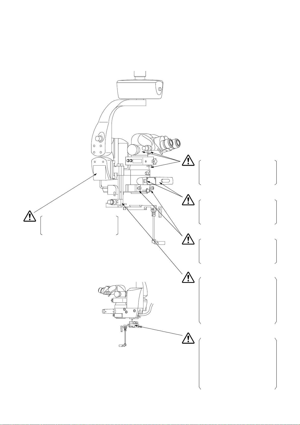
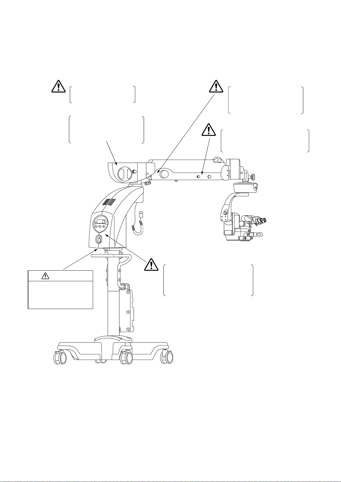
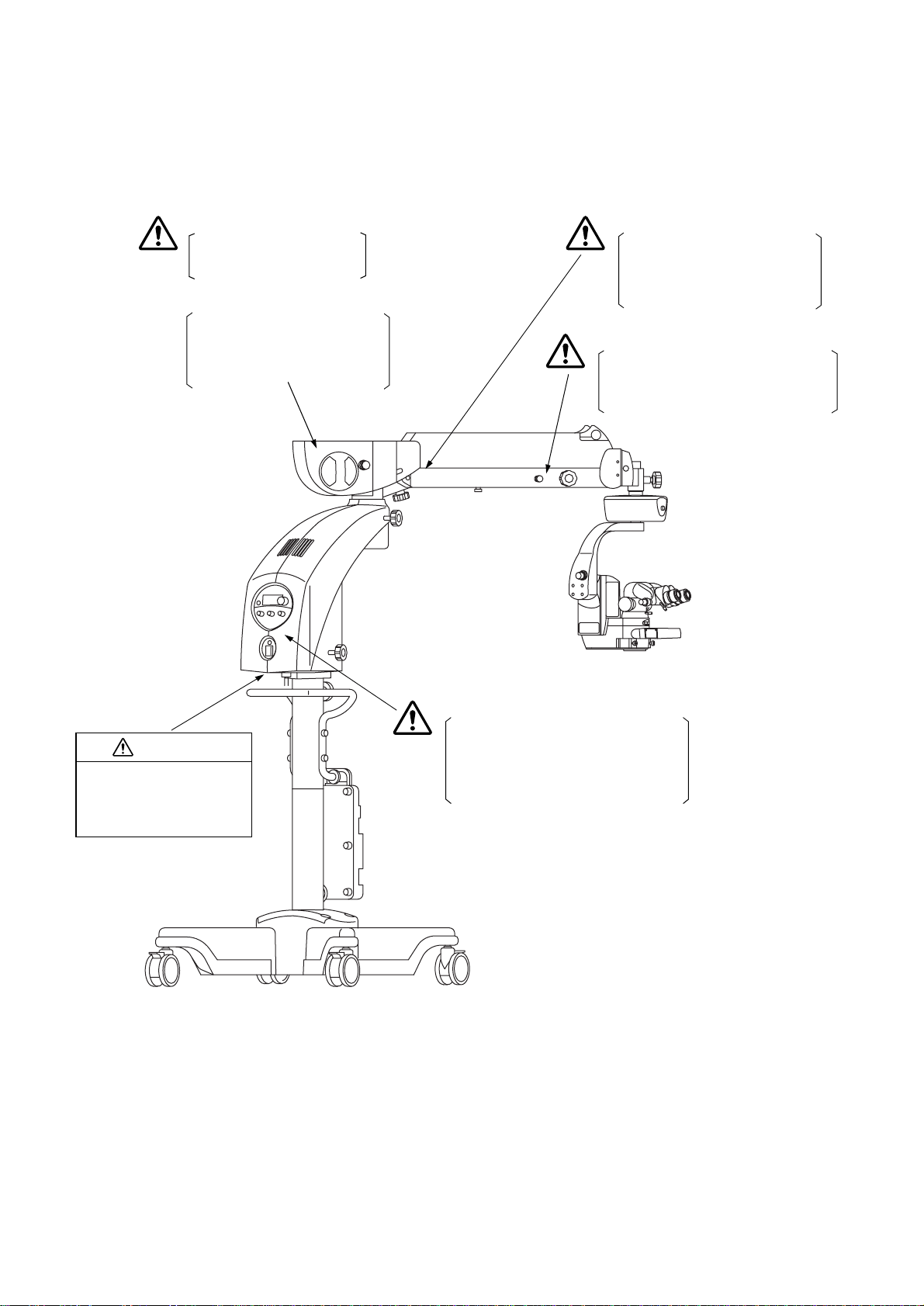
WARNING INDICATIONS AND POSITIONS: OFFISS
This instrument provides warnin gs to ensure safety.
Use this instrument correctly, following those warning instructions. If any of the following marking labels
are missing, contact your distri butor.
WARNING
Before using this instrument, make sure
that the handles, levers, knobs and
rings with red marks are securely
tightened. Any of these falling off could
cause injury or even death.
WARNING
Adjust the front lens and the treatment
section, taking care not to hit the patient
with the front lens. This could injure the
patient.
WARNING
Hold the microscope operation handle
while pressing the electromagnetic lock
release switch to unlock it. The arm
may rotate or move up and down
suddenly, causing an injury.
WARNING
Before using this instrument, make sure
that the handles, levers, knobs and
rings with red marks are securely
tightened. Any of these falling off could
cause injury or even death.
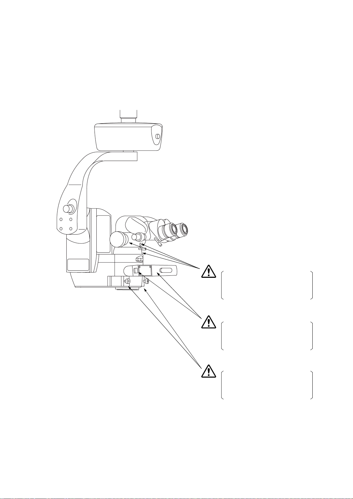
WARNING
Before setting the front lens, move the
microscope at least 200mm upwards.
Otherwise, the components may come
into contact with each other and cause
an injury.
Make sure that the front lens unit is
securely attached to the optical unit
after connecting the two. The front lens
may move suddenly, causing an injury.
WARNING
When installing the front lens unit, make
sure that the front lens unit fixing lever is
fixed securely at the LOC side. An
injury may be caused by the front lens
unit falling off.
When setting/storing the front lens unit,
make sure that the front lens unit fixing
lever is fixed securely at the LOC side.
An injury may be caused by the front
lens unit falling off.
9
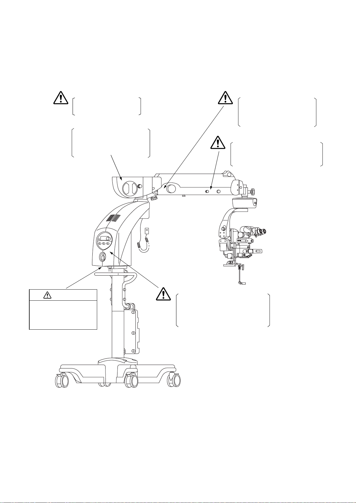
Page 11
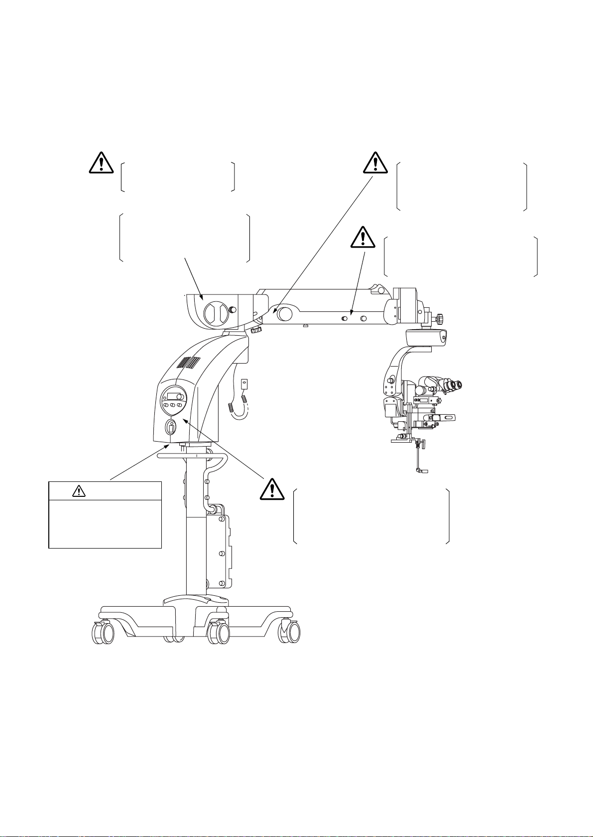
WARNING
Use only the specified lamp.
Otherwise, overheating may
cause a fire.
CAUTION
Handle the lamp house with care
during and immediately following
operation. The lamp house heats
up while in operation and can
cause burns.
WARNING
Before using this instrument,
adjust the balance of the 2nd arm.
The 2nd arm may move up and
down suddenly during operation,
causing an injury.
WARNING
Release the 2nd arm lower limit lock
while holding it at the end. The 2nd arm
may move up and down suddenly,
causing an injury.
CAUTION
Do not open the instrument as
an electric shock may ensue.
Ask qualified service
personnel to repair the
instrument.
WARNING
If you need to use the coaxial illumination
during an ophthalmic operation, make
sure you use the minimum illumination
sufficient for operation. Exposing the
patient’s retina to excessive light may
lead to retinal trouble.
10
Page 12

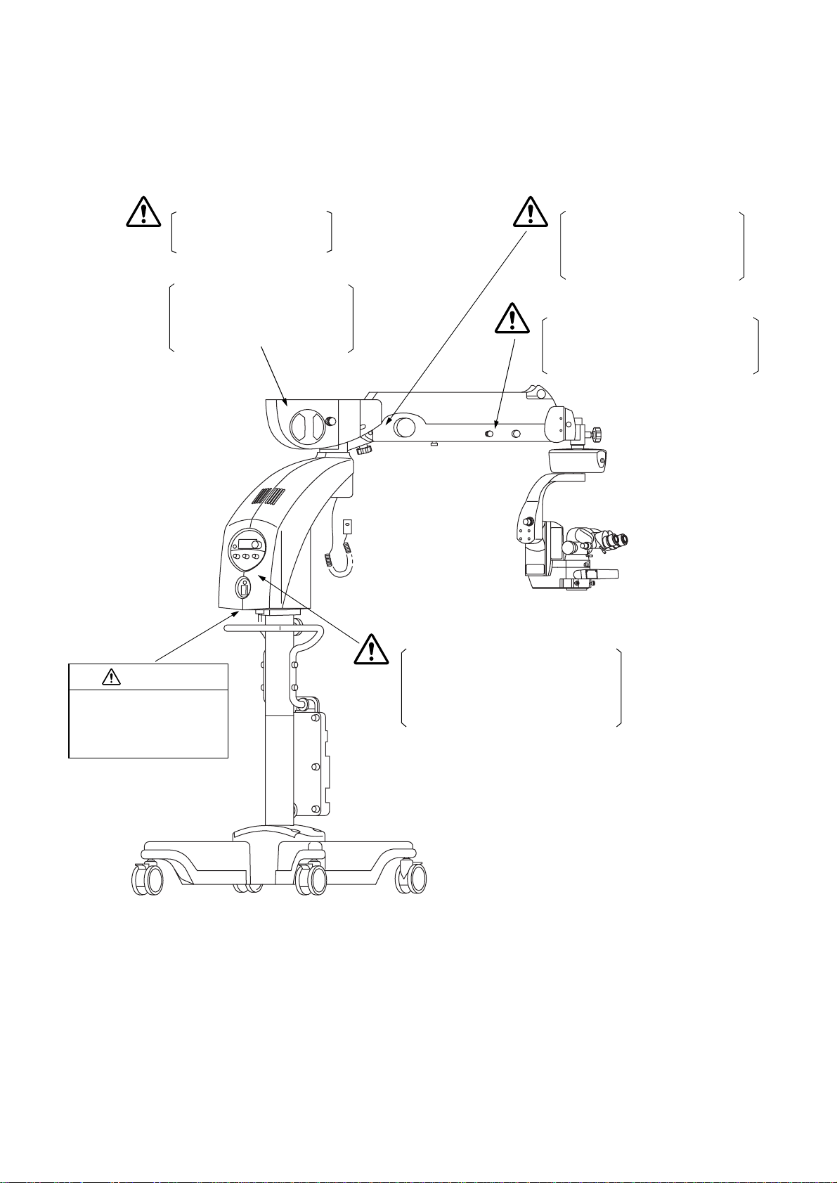
WARNING INDICATIONS AND POSITIONS: OFFISS Lite
This instrument provides warnin gs to ensure safety.
Use this instrument correctly, following those warning instructions. If any of the following marking labels
are missing, contact your distri butor.
WARNING
Before using this instrument, make sure
that the handles, levers, knobs and
rings with red marks are securely
tightened. Any of these falling off could
cause injury or even death.
WARNING
Adjust the front lens and the treatment
section, taking care not to hit the patient
with the front lens. This could injure the
patient.
WARNING
Hold the microscope operation handle
while pressing the electromagnetic lock
release switch to unlock it. The arm
may rotate or move up and down
suddenly, causing an injury.
WARNING
Before using this instrument, make sure
that the handles, levers, knobs and
rings with red marks are securely
tightened. Any of these falling off could
cause injury or even death.
WARNING
Before setting the front lens, move the
microscope at least 200mm upwards.
Otherwise, the components may come
into contact with each other and cause
an injury.
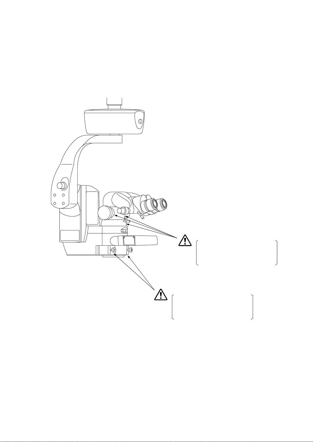
Make sure that the front lens unit is
securely attached to the optical unit
after connecting the two. The front lens
may move suddenly, causing an injury.
WARNING
When installing the front lens unit, make
sure that the front lens unit fixing lever is
fixed securely at the LOC side. An
injury may be caused by the front lens
unit falling off.
When setting/storing the front lens unit,
make sure that the front lens unit fixing
lever is fixed securely at the LOC side.
An injury may be caused by the front
lens unit falling off.
11
Page 13
WARNING
Use only the specified lamp.
Otherwise, overheating may
cause a fire.
CAUTION
Handle the lamp house with care
during and immediately following
operation. The lamp house heats
up while in operation and can
cause burns.
WARNING
Before using this instrument,
adjust the balance of the 2nd arm.
The 2nd arm may move up and
down suddenly during operation,
causing an injury.
WARNING
Release the 2nd arm lower limit lock
while holding it at the end. The 2nd arm
may move up and down suddenly,
causing an injury.
CAUTION
Do not open the instrument as
an electric shock may ensue.
Ask qualified service
personnel to repair the
instrument.
WARNING
If you need to use the coaxial illumination
during an ophthalmic operation, make
sure you use the minimum illumination
sufficient for operation. Exposing the
patient’s retina to excessive light may
lead to retinal trouble.
12
Page 14

WARNING INDICATIONS AND POSITIONS: Pro
This instrument provides warnin gs to ensure safety.
Use this instrument correctly, following those warning instructions. If any of the following marking labels
are missing, contact your distri butor.
WARNING
Before using this instrument, make sure
that the handles, levers, knobs and
rings with red marks are securely
tightened. Any of these falling off could
cause injury or even death.
WARNING
Hold the microscope operation handle
while pressing the electromagnetic lock
release switch to unlock it. The arm
may rotate or move up and down
suddenly, causing an injury.
WARNING
Before using this instrument, make sure
that the handles, levers, knobs and
rings with red marks are securely
tightened. Any of these falling off could
cause injury or even death.
13
Page 15
WARNING
Use only the specified lamp.
Otherwise, overheating may
cause a fire.
CAUTION
Handle the lamp house with care
during and immediately following
operation. The lamp house heats
up while in operation and can
cause burns.
WARNING
Before using this instrument,
adjust the balance of the 2nd arm.
The 2nd arm may move up and
down suddenly during operation,
causing an injury.
WARNING
Release the 2nd arm lower limit lock
while holding it at the end. The 2nd arm
may move up and down suddenly,
causing an injury.
CAUTION
Do not open the instrument as
an electric shock may ensue.
Ask qualified service
personnel to repair the
instrument.
WARNING
If you need to use the coaxial illumination
during an ophthalmic operation, make
sure you use the minimum illumination
sufficient for operation. Exposing the
patient’s retina to excessive light may
lead to retinal trouble.
14
Page 16
WARNING INDICATIONS AND POSITIONS: Pro Lite
This instrument provides warnin gs to ensure safety.
Use this instrument correctly, following those warning instructions. If any of the following marking labels
are missing, contact your distri butor.
WARNING
Before using this instrument, make sure
that the handles, levers, knobs and
rings with red marks are securely
tightened. Any of these falling off could
cause injury or even death.
WARNING
Hold the microscope operation handle
while pressing the electromagnetic lock
release switch to unlock it. The arm
may rotate or move up and down
suddenly, causing an injury.
WARNING
Before using this instrument, make sure
that the handles, levers, knobs and
rings with red marks are securely
tightened. Any of these falling off could
cause injury or even death.
15
Page 17
WARNING
Use only the specified lamp.
Otherwise, overheating may
cause a fire.
CAUTION
Handle the lamp house with care
during and immediately following
operation. The lamp house heats
up while in operation and can
cause burns.
WARNING
Before using this instrument,
adjust the balance of the 2nd arm.
The 2nd arm may move up and
down suddenly during operation,
causing an injury.
WARNING
Release the 2nd arm lower limit lock
while holding it at the end. The 2nd arm
may move up and down suddenly,
causing an injury.
CAUTION
Do not open the instrument as
an electric shock may ensue.
Ask qualified service
personnel to repair the
instrument.
WARNING
If you need to use the coaxial illumination
during an ophthalmic operation, make
sure you use the minimum illumination
sufficient for operation. Exposing the
patient’s retina to excessive light may
lead to retinal trouble.
16
Page 18
WARNING INDICATIONS AND POSITIONS: Standard
This instrument provides warnin gs to ensure safety.
Use this instrument correctly, following those warning instructions. If any of the following marking labels
are missing, contact your distri butor.
WARNING
Before using this instrument, make sure
that the handles, levers, knobs and
rings with red marks are securely
tightened. Any of these falling off could
cause injury or even death.
WARNING
Before using this instrument, make sure
that the handles, levers, knobs and
rings with red marks are securely
tightened. Any of these falling off could
cause injury or even death.
17
Page 19
WARNING
Use only the specified lamp.
Otherwise, overheating may
cause a fire.
CAUTION
Handle the lamp house with care
during and immediately following
operation. The lamp house heats
up while in operation and can
cause burns.
WARNING
Before using this instrument,
adjust the balance of the 2nd arm.
The 2nd arm may move up and
down suddenly during operation,
causing an injury.
WARNING
Release the 2nd arm lower limit lock
while holding it at the end. The 2nd arm
may move up and down suddenly,
causing an injury.
CAUTION
Do not open the instrument as
an electric shock may ensue.
Ask qualified service
personnel to repair the
instrument.
WARNING
If you need to use the coaxial illumination
during an ophthalmic operation, make
sure you use the minimum illumination
sufficient for operation. Exposing the
patient’s retina to excessive light may
lead to retinal trouble.
18
Page 20

CONTENTS
INTRODUCTION ................ ...... ....... ...... ... ...... ...... ....... ...... ...... ... ...... ....... ...... ...... ... ...... ....... ...... ...... ..........1
DISPLAY FOR SAFE USE .............. .................. ................... ................ .................. ................... .............4
SAFETY CAUTIONS ...............................................................................................................................5
MAINTENANCE ........... ................... .................. ................ .................. ................... ................... ................8
USER MAINTENANCE ............................ ... ... ...................... ... ... ...................... ... ... ... ..........................8
ESCAPE CLAUSE ...................................................................................................................................8
WARNING INDICATIONS AND POSITIONS: OFFISS ................................................................... 9
WARNING INDICATIONS AND POSITIONS: OFFISS Lite ..................... ...................... ..............11
WARNING INDICATIONS AND POSITIONS: Pro ......................................................................... 13
WARNING INDICATIONS AND POSITIONS: Pro Lite .......... ................... ................... ............... .. 15
WARNING INDICATIONS AND POSITIONS: Standard .............................................................. 17
NOMENCLATURE
OFFISS .............................................................................................................................................22
STANDARD ACCESSORIES: OFFISS .............................................................................................23
OFFISS Lite ... ... ..................... .... ..................... ... ...................... ... ...................... ... ..............................24
STANDARD ACCESSORIES: OFFISS Lite ......................................................................................25
Pro .......... ................... ................ .................. ................... ................... .................. ..............................26
STANDARD ACCESSORIES: Pro ....................................................................................................27
Pro Lite ..............................................................................................................................................28
STANDARD ACCESSORIES: Pro Lite .............................................................................................29
Standard .... ...................... ...................... ...................... ...................... .................. ..............................30
STANDARD ACCESSORIES: Standard ...........................................................................................31
PREPARATIONS BEFORE USE
STERILIZED CAP: Common .............................................................................................................32
PREPARATIONS FOR STERILIZING THE FRONT LENS UNIT: OFFISS, OFFISS Lite ................32
TURNING ON THE POWER: Common ............................................................................................32
CHECKING THE SPARE LAM P: Com m o n .............. ... ... ... ... ...................... ... ... ...................... ... ... .....33
SETTING ACCESSORIES: OFFISS, OFFISS Lite, Pro, Pro Lite .....................................................34
SETTING THE ACCESSORIES: Standard .......................................................................................36
INSTALLING THE INVERTER: OFFISS, OFFISS Lite .....................................................................38
REMOVING THE INVERTER: OFFISS, OFFISS Lite .......................................................................39
ADJUSTING THE 2ND ARM BALANCE: OFFISS, OFFISS Lite, Pro, Pro Lite ................................41
ADJUSTING THE 2ND ARM BALANCE: Standard ..........................................................................41
SETTING THE 2ND ARM LOWER LIMIT POSITION: OFFISS, OFFISS Lite, Pro, Pro Lite ............42
SETTING THE 2ND ARM LOWER LIMIT POSITION: Standard ......................................................44
INITIALIZATIO N: O FF ISS, Pro ................... ... ... .... ... ..................... .... ..................... ... ........................46
INITIALIZATION: OFFISS Lite, Pro Lite, Standard ...........................................................................47
LOCKING/UNLOCKING THE 2ND ARM LOWER LIMIT: OFFISS, OFFISS Lite, Pro, Pro Lite .......48
LOCKING/UNLOCKING THE 2ND ARM LOWER LIMIT: Standard .................................................50
ADJUSTING THE DIOPTRIC POWER: Common ............................................................................52
INSTALLING THE STERILIZED CAP: OFFISS, OFFISS Lite ..........................................................53
INSTALLING THE STERILIZED CAP: Pro, Pro Lite .........................................................................53
INSTALLING THE STERILIZED CAP: Standard ..............................................................................54
ADJUSTING THE PUPIL LA RY DISTANCE: Common ........................ ... ... ... ... ...................... ... ... ... ..54
19
Page 21

ADJUSTING THE OBSERVATION ANGLE: Common .....................................................................54
ADJUSTING THE LIGHT INTENSITY: OFFISS, OFFISS Lite ..........................................................55
ADJUSTING THE LIGHT INTENSITY: Pro, Pro Lite, Standard ........................................................55
OPERATION PANEL: Common ........................................................................................................56
FOOT SWITCH: OFFISS, OFFISS Lite ............................................................................................56
FOOT SWITCH: Pro, Pro Lite ...........................................................................................................57
FOOT SWITCH: Stand a rd .. ... ...................... ... ...................... ... ... ...................... ... ...................... ........57
INSTALLING THE FRONT LENS UNIT: OFFISS, OFFISS Lite .......................................................57
OPERATIONS IN USE
OPERATION OF FOOT SWITCH: OFFISS ......................................................................................59
OPERATION OF FOOT SWITCH: OFFISS Lite ...............................................................................60
OPERATION OF FOOT SWITCH: Pro .............................................................................................61
OPERATION OF FOOT SWITCH: Pro Lite .......................................................................................62
OPERATION OF FOOT SWITCH: Standard ....................................................................................63
OPERATION OF MANUAL KNOBS: OFFISS, OFFISS Lite .............................................................64
OPERATION OF MANUAL KNOBS: Pro, Pro Lite ............................................................................64
OPERATION OF MANUAL KNOBS: Standard .................................................................................65
SETTING OF MICROSCOPE INCLINATION POSITION: Common .................................................65
SPEED ADJUSTMENT OF ZOOM/FOCUS/X-Y TRANSLATOR: Common .....................................66
ADJUSTMENT OF FOCUS: OFFISS, OFFISS Lite, Pro, Pro Lite ....................................................67
ADJUSTMENT OF FOCUS: Standard .............. .... ..................... ... .... ..................... ... .... ....................67
ADJUSTMENT OF ZOOM MAGNIFICATION: Common ..................................................................68
CHANGE OF ILLUMINATION ANGLE: OFFISS, OFFISS Lite .........................................................68
CHANGE OF ILLUMINATION ANGLE: Pro, Pro Lite, Standard .......................................................69
CHANGE OF SPECTRAL RATIO FOR BEAM SPLITTER: Common ..............................................70
OPERATION OF THE FRONT LENS: OFFISS, OFFISS Lite ..........................................................70
OPERATION OF THE STEREO VARIATOR: OFFISS, OFFISS Lite ...............................................75
OPERATION OF THE VARIABLE ILLUMINATION APERTURE: OFFISS, OFFISS Lite .................76
HOW TO USE THE ANTERIOR EYE SECTION OBSERVATION LENS: OFFISS, OFFISS Lite ....77
HOW TO USE THE PERIPHERAL OBSERVATION PRISM: OFFISS, OFFISS Lite .......................77
OPERATION OF INVERTER: OFFISS, OFFISS Lite .......................................................................78
REPLACING WITH THE SPARE LAMP: Common ...........................................................................79
PROCEDURE IN EMERGENCY: OFFIS S, OFFISS Lite ........... ... .... ... ... ... ... ...................... ... ... ... ... ..80
PROCEDURE IN EMERGENCY: Pro, Pro Lit e ................. ... ... ...................... ... ... ... ... ...................... ..81
PROCEDURE IN EMERGENCY: Stan d ard ............. ..................... .... ... ... ... ...................... ... ... ... ... .....82
AFTER USE
AFTER USE: Common . ...................... ... ... ...................... ... ... ...................... ... ... ...................... ...........83
MOVING AND STORING: OFFISS, OFFISS Lite, Pro, Pro Lite ... ............................ ................. 83
MOVING AND STORING: Standard ................................................................................................. 85
TROUBLESHOOTING
TROUBLESHOOTING GUIDE ........... ... ...................... ... ...................... ... ...................... ... ... ..............87
ERROR CODES ..... ... ...................... ... ... ...................... ... ... ... ...................... ... ... .................................88
CONSUMABLE PARTS: OFFISS, OFFISS Lite ...............................................................................89
CONSUMABLE PARTS: Pro, Pro Lite ..............................................................................................89
CONSUMABLE PARTS: Standard ....................................................................................................90
20
Page 22

SPECIFICATIONS
BASIC SPECIFICATIONS: Common ................................................................................................91
ELECTROMAGNET IC CO M PA TIBILITY ................. ... ... ... ...................... ... ... ... ...................... ... ... .....91
ELECTRIC RATING ..........................................................................................................................95
CLASSIFICATI ON ................. ...................... ...................... ...................... ...................... ....................95
DIMENSIONS AND WEIGHT ............................................................................................................96
PURPOSE OF USE ........... ... .... ... ... ...................... ... ... ...................... ... ... ...................... ... .................96
OPERATION PRINCIPLE .................................................................................................................96
MAINTENANCE AND INSPECTION: Common
REPLACEMENT OF THE SPARE LAMP .........................................................................................97
OPERATING THE CIRCUIT BREAKER ...........................................................................................98
CHECKING THE POWER OU TL ET ........ ... ...................... ... ... ...................... ... ... ...................... ... ...100
CHECKING INPUT VOLT AG E ................. ... ... ...................... ... ... ...................... ... ... ...................... ...100
CLEANING THE OBJECTIVE LENS / THE EYEPIECE LENS .......................................................101
CLEANING THE FRONT LENS STORING UNIT: OFFISS, OFFISS Lite ......................................101
CLEANING THE REST APART FROM THE OPTICAL SYSTEM ..................................................102
ENSURING THE SAFETY WO RK ........ ... ...................... ... ... ...................... ... ... ...................... ... ... ...102
DAILY CHECK ............. ... ... ... .... ..................... ... .... ..................... ... .... ..................... ... .... ..................103
DISPOSITION .................................................................................................................................103
SYSTEM OUTLINE ......... ... ... ...................... ... ...................... ... ... ...................... ... ................... .........104
PERMITTED WEIGHT FO R ACCE SSO R IES TO BE INS TAL L ED .................. ... ...................... ... ...106
WEIGHT OF OPTIONAL A CCES SO RI ES ..................... ... ...................... ... ... ...................... ... ... ......106
21
Page 23
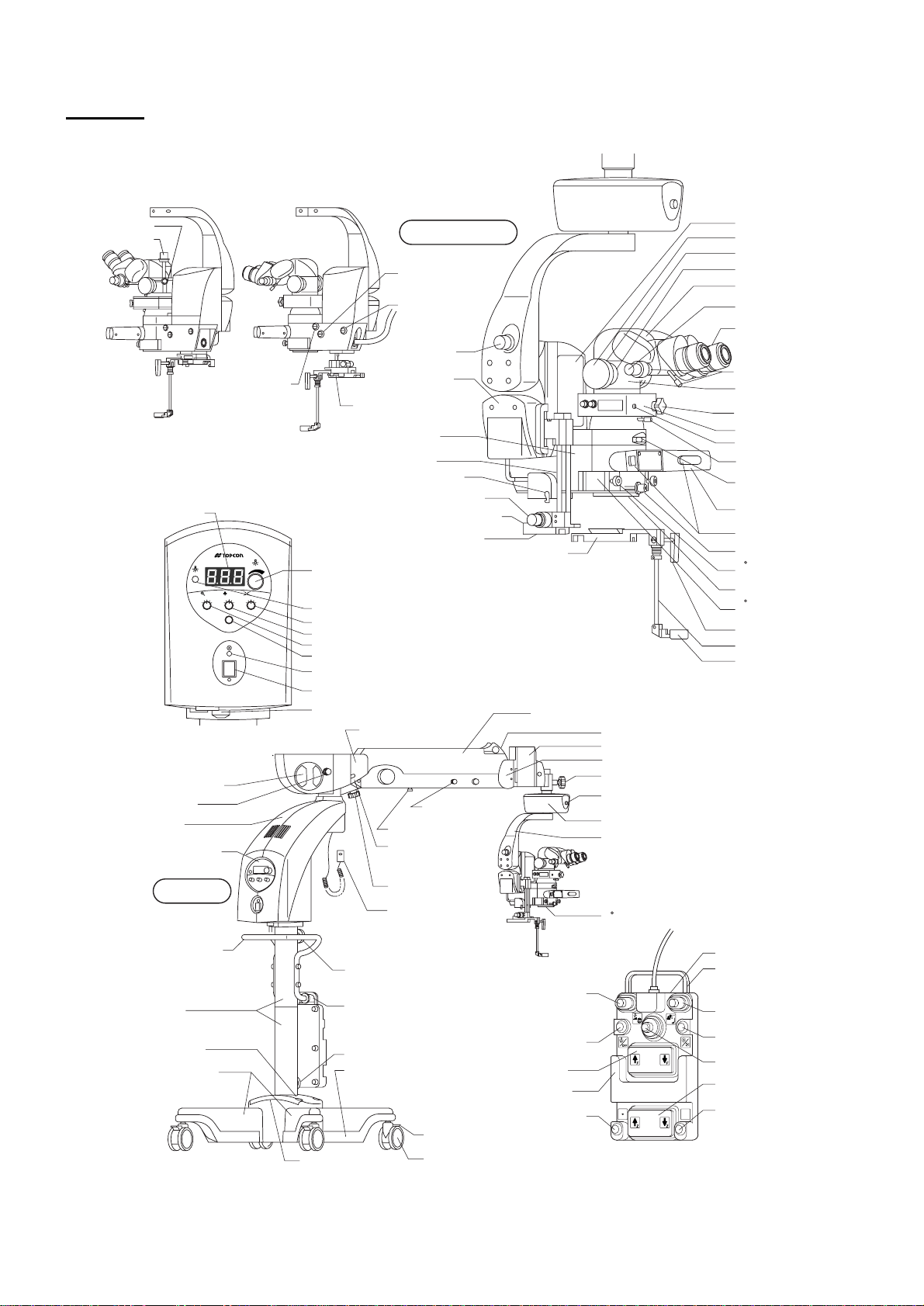
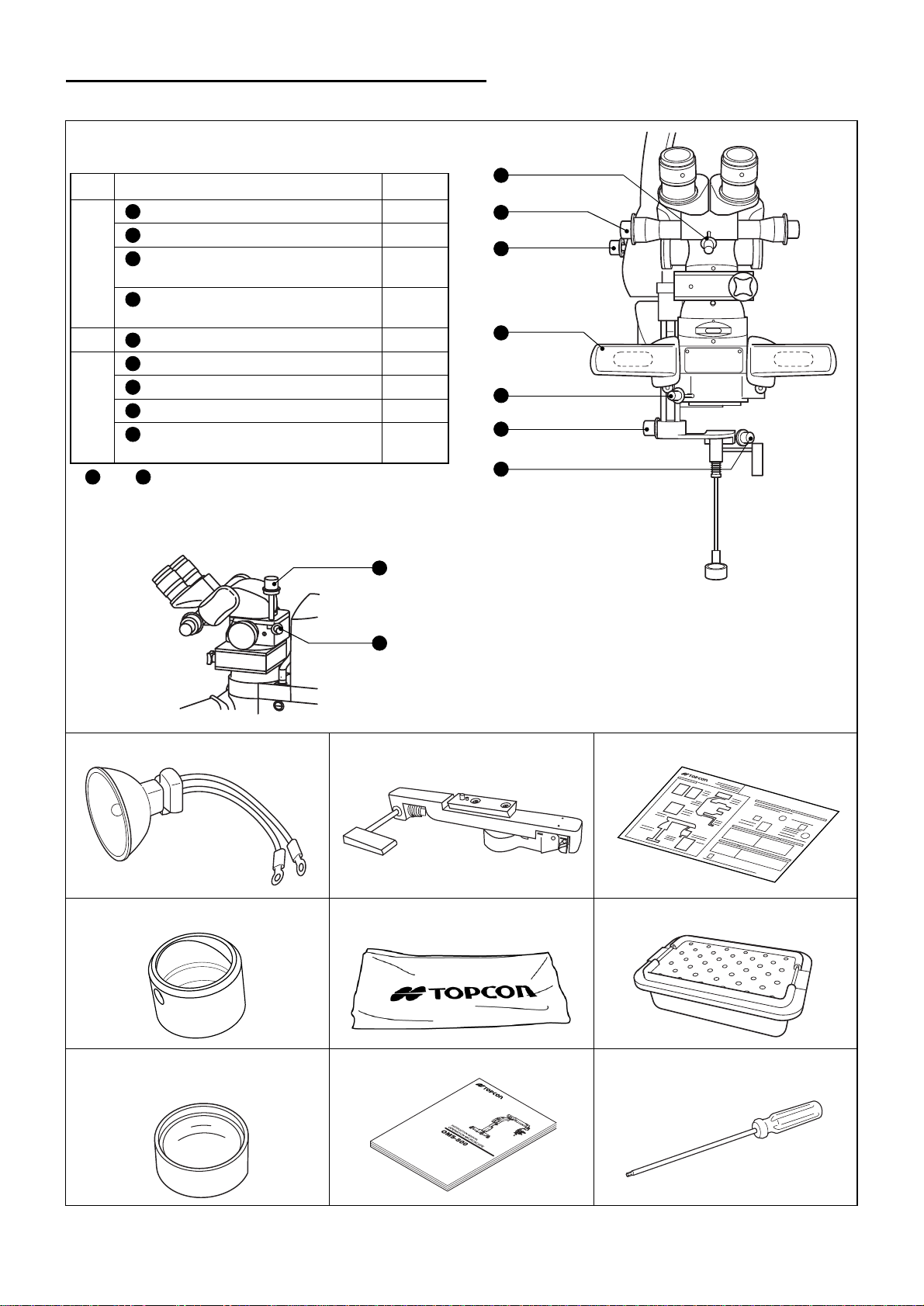
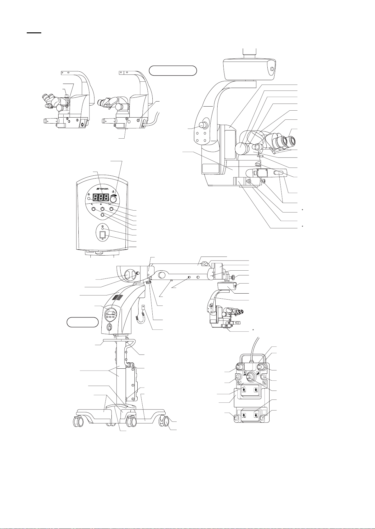
NOMENCLATURE
OFFISS
Type with the changeable beam splitter
Spectral ratio lever
Spectral ratio knob
Light intensity
display window
Zoom manual knob
(for emergency)
SPARE
ZOOM
3
2
1
Lamp house unit
Filter knob
1st arm
Operation panel
Microscope unit
Variable illumination
aperture manual knob
(for emergency)
Illumination angle
manual knob
(for emergency)
Optical unit
inclination knob
Front lens fine
movement unit
Front lens unit
fixing lever
Optical unit
Slide shaft
Connecting hook
Front lens connecting/
disconnecting knob
Front lens connecting unit
Front lens storing unit
MAIN
XY
FOCUS
3
3
2
2
4
4
4
1
1
5
5
5
EXIT
Illumination light intensity
adjustment knob
Spare lamp indicator light
X-Y translator speed knob
Focusing unit speed knob
Zoom speed knob
EXIT switch
Power indicator light
Front lens unit
Focusing unit
Accessories mount cap
Accessories mounting ring
Accessories mount
Variable eyepiece lens
Pupillary distance
adjustment knob
Eyepiece lens
Observation angle handle
Beam splitter or
changeable beam splitter
Manual IN/OUT knob
(for emergency)
Inverter
IN indicator LED
Eyepiece lens/beam
splitter fixing knob
Zoom magnification
display window
Microscope operation
handle
Electromagnetic lock
release switch
Stereo variator lever
0 assistant’s microscope
fixing knob
Objective lens
0 assistant’s microscope
mount
Front lens IN/OUT lever
Front lens holding shaft
Front lens
Power switch
Circuit breaker
2nd arm side-rear cover
2nd arm
End rubber cover
Rough focusing unit
2nd arm side-front cover
X-Y translator rotation fixing handle
2nd arm lower limit
lock release knob
2nd arm lower limit knob
Balance display window
Initial switch
X-Y translator
Focusing unit arm
Base unit
Base movement
handle
Column
Center base
Right/left bases
22
NOMENCLATURE
Bubble level
Cord hanger
Foot switch
hanger
Foot switch
support
Protector
2nd arm balance
adjustment handle
Electromagnetic lock
release switch
Caster lock lever
Caster
Illumination light
intensity adjustment
switch/
variable illumination
operture switch
Illumination blinking
switch
Focus up/down
switch
Foot rest
Invereter in/out switch
0 assistant’s microscope mount cover
Foot switch
Carrying handle
Rough focusing switch/
front lens focusing switch
Illumination angle switch
X-Y translator lever switch
Zoom up/down switch
R
R
Spare switch
*Switch layout when shipped
Page 24
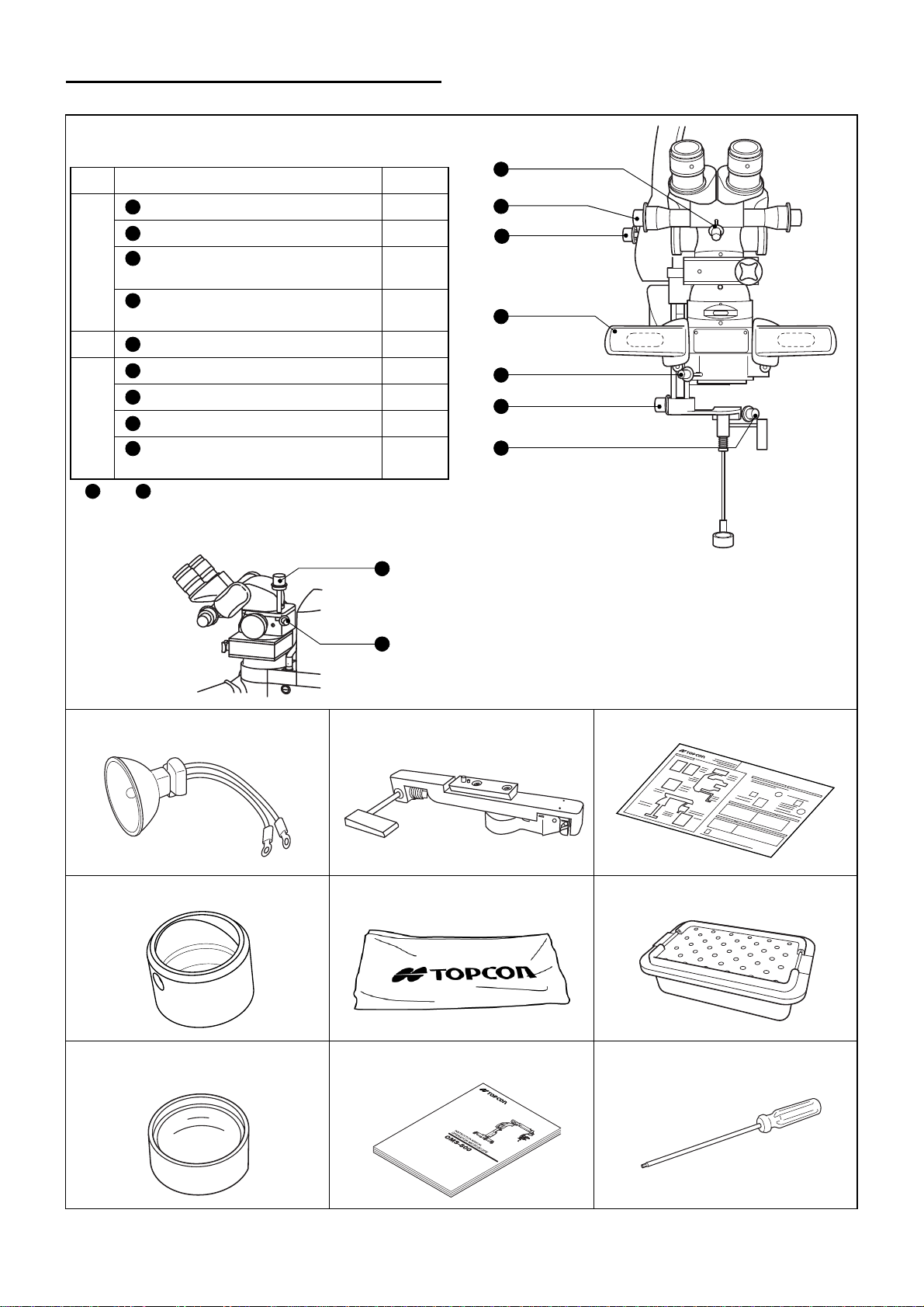
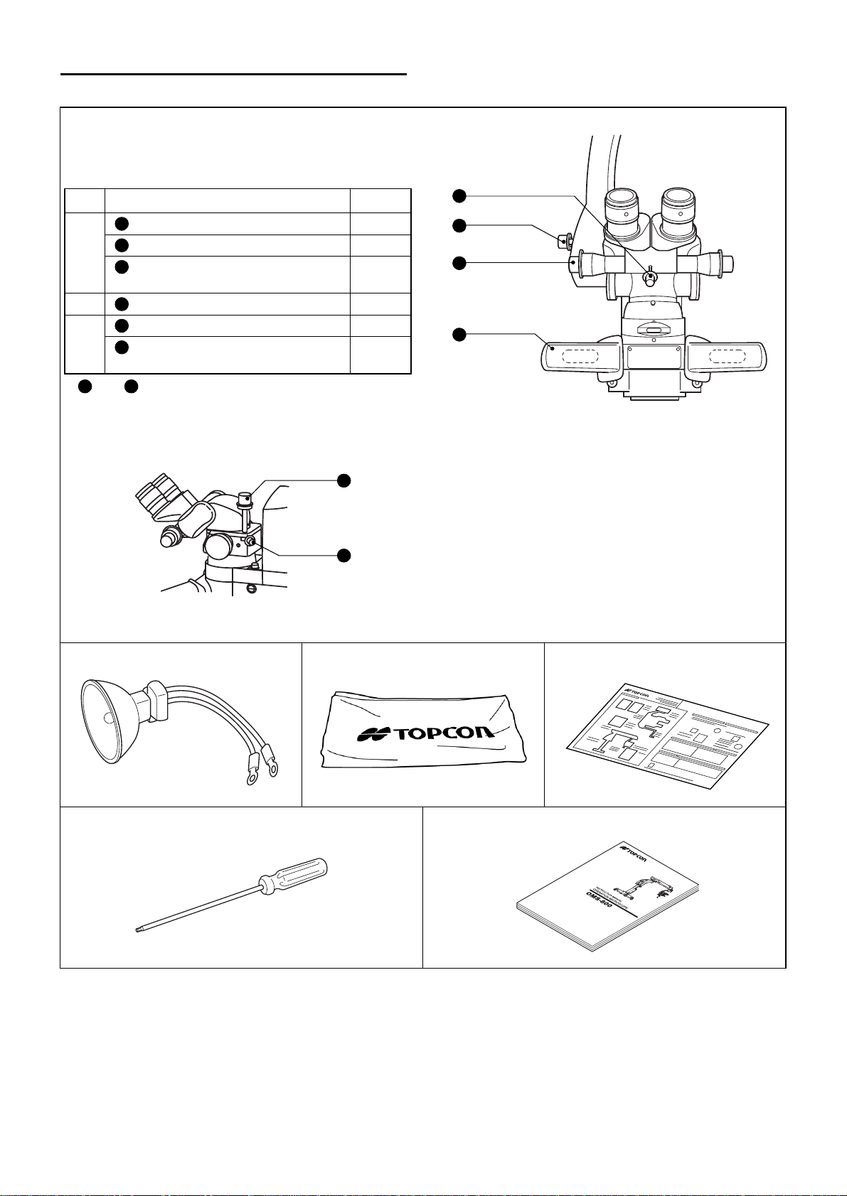
STANDARD ACCESSORIES: OFFISS
e
Sterilized cap
Material : Silicon (Latex free)
Type Position Quantity
4
1
Optical unit inclination knob
2
Pupillary distance adjustment knob
6
A
B
C
8 9
* and are attached to only the type equipped with th
changeable beam splitter.
Front lens connecting/disconnecting
knob
8
Spectral ratio knob of changeable
beam splitter
3
Microscope operation handle
4
Observation angle handle
5
Stereo va riat or leve r
7
Front lens unit fixing lever
9
Spectral ratio lever of changeable
beam splitter
1
2
1
1
2
1
1
1
1
Type with the changeable beam splitter
8
9
2
1
3
5
6
7
Lamp (2): Already installed. Front lens unit (1) Quick reference (2)
Peripheral observation prism (1) Cover (1) Sterilized tray (1)
Anterior eye section observation
In st r uc t i o n m a n ua l (1 ) : Th i s ma n ua l Hexagonal wrench (1)
lens (1)
23
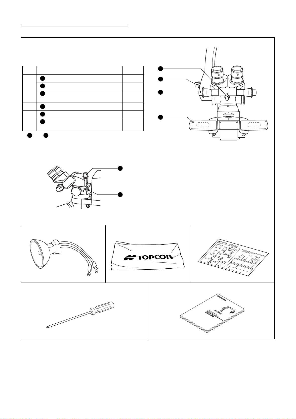
NOMENCLATURE
Page 25
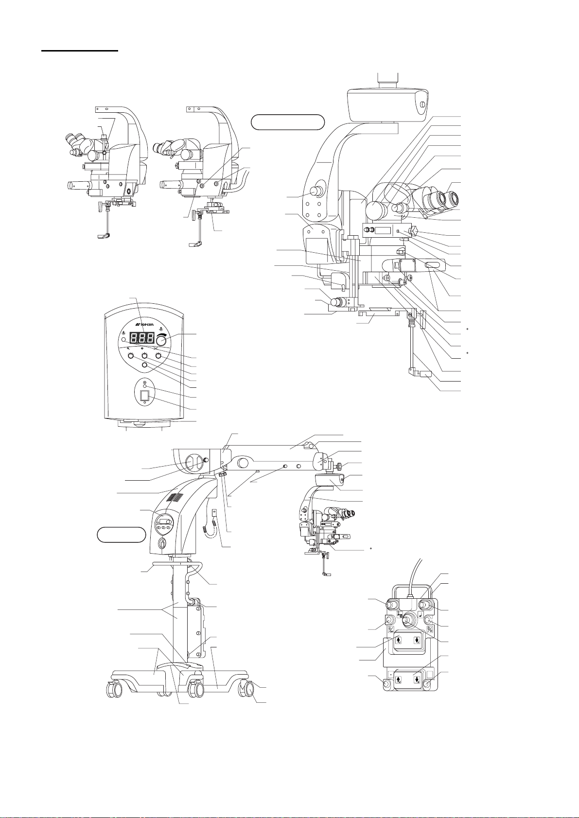
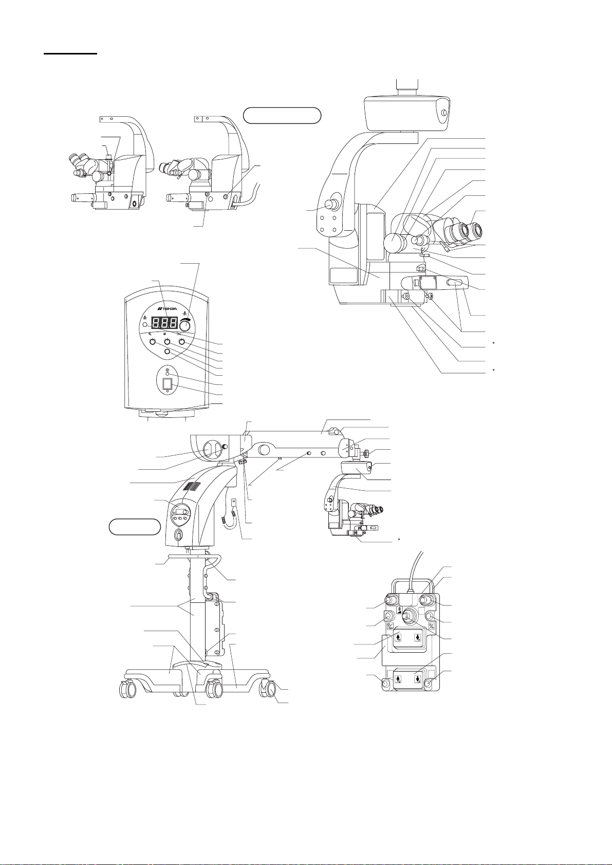
OFFISS Lite
Type with the changeable beam splitter
Spectral ratio lever
Spectral ratio knob
Light intensity
display window
Zoom manual knob
(for emergency)
SPARE
ZOOM
3
2
1
Lamp house unit
Filter knob
1st arm
Operation panel
Microscope unit
Variable illumination
aperture manual knob
(for emergency)
Illumination angle
manual knob
(for emergency)
Optical unit
inclination knob
Front lens fine
movement unit
Front lens unit
fixing lever
Optical unit
Slide shaft
Connecting hook
Front lens connecting/
disconnecting knob
Front lens connecting unit
Front lens storing unit
MAIN
XY
FOCUS
3
3
2
2
4
4
4
1
1
5
5
5
EXIT
Illumination light intensity
adjustment knob
Spare lamp indicator light
X-Y translator speed knob
Focusing unit speed knob
Zoom speed knob
EXIT switch
Power indicator light
Front lens unit
Focusing unit
Accessories mount cap
Accessories mounting ring
Accessories mount
Variable eyepiece lens
Pupillary distance
adjustment knob
Eyepiece lens
Observation angle handle
Beam splitter or
changeable beam splitter
Manual IN/OUT knob
(for emergency)
Inverter
IN indicator LED
Eyepiece lens/beam
splitter fixing knob
Zoom magnification
display window
Microscope operation
handle
Electromagnetic lock
release switch
Stereo variator lever
0 assistant’s microscope
fixing knob
Objective lens
0 assistant’s microscope
mount
Front lens IN/OUT lever
Front lens holding shaft
Front lens
Power switch
Circuit breaker
2nd arm side-rear cover
2nd arm
End rubber cover
2nd arm side-front cover
X-Y translator rotation fixing handle
2nd arm lower limit
lock release knob
2nd arm lower limit knob
Balance display window
Initial switch
X-Y translator
Focusing unit arm
Base unit
Base movement
handle
Column
Center base
Right/left bases
24
NOMENCLATURE
Bubble level
2nd arm balance
adjustment handle
Electromagnetic lock
release switch
Cord hanger
Foot switch
hanger
Foot switch
support
Protector
Caster lock lever
Caster
Illumination light
intensity adjustment
switch/
variable illumination
operture switch
Illumination blinking
switch
Focus up/down
switch
Foot rest
Inverter in/out switch
0 assistant’s microscope mount cover
Foot switch
Carrying handle
Front lens focusing switch
Illumination angle switch
X-Y translator lever switch
Zoom up/down switch
R
R
Spare switch
*Switch layout when shipped
Page 26
STANDARD ACCESSORIES: OFFISS Lite
e
Sterilized cap
Material : Silicon (Latex free)
Type Position Quantity
1
Optical unit inclination knob
2
Pupillary distance adjustment knob
6
A
B
C
8 9
* and are attached to only the type equipped with th
changeable beam splitter.
Front lens connecting/disconnecting
knob
8
Spectral ratio knob of changeable
beam splitter
3
Microscope operation handle
4
Observation angle handle
5
Stereo va riat or leve r
7
Front lens unit fixing lever
9
Spectral ratio lever of changeable
beam splitter
1
2
1
1
2
1
1
1
1
4
2
1
3
5
6
7
Type with the changeable beam splitter
8
9
Lamp (2): Already installed. Front lens unit (1) Quick reference (2)
Peripheral observation prism (1) Cover (1) Sterilized tray (1)
Anterior eye section observation
lens (1)
In st r uc t i o n m a n ua l (1 ) : Th i s ma n ua l Hexagonal wrench (1)
NOMENCLATURE
25
Page 27
Pro
Type with the changeable beam splitter
Spectral ratio lever
Spectral ratio knob
Zoom manual knob
(for emergency)
Illumination light intensity
adjustment knob
Light intensity
display window
SPARE
ZOOM
1
Lamp house unit
Filter knob
1st arm
Operation panel
Microscope unit
Focusing unit
Accessories mount cap
Illumination angle
manual knob
(for emergency)
Optical unit
inclination knob
Optical unit
MAIN
XY
FOCUS
3
3
2
3
2
2
4
4
4
1
1
5
5
5
EXIT
Spare lamp indicator light
X-Y translator speed knob
Focusing unit speed knob
Zoom speed knob
EXIT switch
Power indicator light
Power switch
Circuit breaker
2nd arm side-rear cover
2nd arm
End rubber cover
Rough focusing unit
2nd arm side-front cover
X-Y translator rotation fixing handle
2nd arm lower limit
lock release knob
2nd arm lower limit knob
Initial switch
X-Y translator
Focusing unit arm
Balance display window
Accessories mounting ring
Accessories mount
Variable eyepiece lens
Pupillary distance
adjustment knob
Eyepiece lens
Observation angle handle
Beam splitter or
changeable beam splitter
Eyepiece lens/beam
splitter fixing knob
Zoom magnification
display window
Microscope operation
handle
Electromagnetic lock
release switch
0 assistant’s microscope
fixing knob
Objective lens
0 assistant’s microscope
mount
Base unit
Base movement
handle
Column
Center base
Right/left bases
Bubble level
2nd arm balance
adjustment handle
Electromagnetic lock
release switch
Cord hanger
Foot switch hanger
Foot switch support
Protector
Illumination light
intensity adjustment
switch
Illumination blinking
switch
Focus up/down
switch
Foot rest
Spare switch
Caster lock lever
Caster
0 assistant’s microscope mount cover
Foot switch
Carrying handle
Rough focusing switch
Illumination angle switch
X-Y translator lever switch
Zoom up/down switch
Spare switch
*Switch layout when shipped
26
NOMENCLATURE
Page 28
STANDARD ACCESSORIES: Pro
e
Sterilized cap
Material : Silicon (Latex free)
Type Position Quantity
1
Optical unit inclination knob
2
A
B
C
8 9
* and are attached to only the type equipped with th
changeable beam splitter.
Pupillary distance adjustment knob
8
Spectral ratio knob of changeable
beam splitt er
3
Microscope operation handle
4
Observation angle handle
9
Spectral ratio lever of changeable
beam splitt er
Type with the changeable beam splitter
1
2
1
2
1
1
8
4
1
2
3
9
Lamp (2): Already installed. Cover (1) Quick reference (2)
Hexagonal wrench (1) Instruction manual (1): This manual
27
NOMENCLATURE
Page 29
Pro Lite
Type with the changeable beam splitter
Spectral ratio lever
Spectral ratio knob
Zoom manual knob
(for emergency)
Illumination light intensity
adjustment knob
Light intensity
display window
SPARE
ZOOM
1
Lamp house unit
Filter knob
1st arm
Operation panel
Microscope unit
Focusing unit
Accessories mount cap
Illumination angle
manual knob
(for emergency)
Optical unit
inclination knob
Optical unit
MAIN
XY
FOCUS
3
3
2
3
2
2
4
4
4
1
1
5
5
5
EXIT
Spare lamp indicator light
X-Y translator speed knob
Focusing unit speed knob
Zoom speed knob
EXIT switch
Power indicator light
Power switch
Circuit breaker
2nd arm side-rear cover
2nd arm
End rubber cover
2nd arm side-front cover
X-Y translator rotation fixing handle
2nd arm lower limit
lock release knob
2nd arm lower limit knob
Initial switch
X-Y translator
Focusing unit arm
Balance display window
Accessories mounting ring
Accessories mount
Variable eyepiece lens
Pupillary distance
adjustment knob
Eyepiece lens
Observation angle handle
Beam splitter or
changeable beam splitter
Eyepiece lens/beam
splitter fixing knob
Zoom magnification
display window
Microscope operation
handle
Electromagnetic lock
release switch
0 assistant’s microscope
fixing knob
Objective lens
0 assistant’s microscope
mount
Base unit
Base movement
handle
Column
Center base
Right/left bases
Bubble level
2nd arm balance
adjustment handle
Electromagnetic lock
release switch
Cord hanger
Foot switch hanger
Foot switch support
Protector
Illumination light
intensity adjustment
switch
Illumination blinking
switch
Focus up/down
switch
Foot rest
Spare switch
Caster lock lever
Caster
0 assistant’s microscope mount cover
Foot switch
Carrying handle
Spare switch
Illumination angle switch
X-Y translator lever switch
Zoom up/down switch
Spare switch
*Switch layout when shipped
28
NOMENCLATURE
Page 30
STANDARD ACCESSORIES: Pro Lite
e
Sterilized cap
Material : Silicon (Latex free)
Type Position Quantity
1
Optical unit inclination knob
2
A
B
C
8 9
* and are attached to only the type equipped with th
changeable beam splitter.
Pupillary distance adjustment knob
8
Spectral ratio knob of changeable
beam splitt er
3
Microscope operation handle
4
Observation angle handle
9
Spectral ratio lever of changeable
beam splitt er
Type with the changeable beam splitter
1
2
1
2
1
1
8
4
1
2
3
9
Lamp (2): Already installed. Cover (1) Quick reference (2)
Hexagonal wrench (1) nstruction manual (1): This manual
29
NOMENCLATURE
Page 31

Standard
Type with the changeable beam splitter
Spectral ratio lever
Spectral ratio knob
Zoom manual knob
(for emergency)
Illumination light intensity
adjustment knob
Light intensity
display window
Microscope unit
Focusing unit
Accessories mount cap
Illumination angle
manual knob
(for emergency)
Optical unit
inclination knob
Optical unit
SPARE
ZOOM
3
2
1
MAIN
XY
FOCUS
3
3
2
2
4
4
4
1
1
5
5
5
EXIT
Spare lamp indicator light
X-Y translator speed knob
Focusing unit speed knob
Zoom speed knob
EXIT switch
Power indicator light
Accessories mounting ring
Accessories mount
Variable eyepiece lens
Pupillary distance
adjustment knob
Eyepiece lens
Observation angle handle
Beam splitter or
changeable beam splitter
Eyepiece lens/beam
splitter fixing knob
Zoom magnification
display window
Microscope operation
handle
0 assistant’s microscope
fixing knob
Objective lens
0 assistant’s microscope
mount
Lamp house unit
Filter knob
1st arm
Operation panel
Base unit
Base movement
handle
Column
Center base
Right/left bases
Power switch
Circuit breaker
Bubble level
2nd arm side-rear cover
2nd arm lower
limit knob
Balance display
window
2nd arm balance
adjustment handle
2nd arm rotation
fixing handle
1st arm rotation fixing handle
Cord hanger
Foot switch hanger
Foot switch support
Protector
2nd arm
lower limit lock
release knob
Illumination light
intensity adjustment
switch
Illumination blinking
switch
Focus up/down
switch
Foot rest
Spare switch
Caster lock lever
Caster
2nd arm
End rubber cover
2nd arm vertical movement fixing handle
2nd arm side-front cover
X-Y translator rotation fixing handle
Initial switch
X-Y translator
Focusing unit arm
0 assistant’s microscope mount cover
*Switch layout when shipped
Foot switch
Carrying handle
Spare switch
Illumination angle switch
X-Y translator lever switch
Zoom up/down switch
Spare switch
30
NOMENCLATURE
Page 32

STANDARD ACCESSORIES: Standard
e
Sterilized cap
Material : Silicon (Latex free)
Type Position Quantity
1
Optical unit inclination knob
2
A
B
C
8 9
* and are attached to only the type equipped with th
changeable beam splitter.
Pupillary distance adjustment knob
8
Spectral ratio knob of changeable
beam splitt er
3
Microscope operation handle
4
Observation angle handle
9
Spectral ratio lever of changeable
beam splitt er
1
2
1
2
1
1
Type with the changeable beam splitter
8
9
4
1
2
3
Lamp (2): Already installed. Cover (1) Quick reference (2)
Hexagonal wrench (1) Instru ction manual (1): This manual
31
NOMENCLATURE
Page 33

PREPARATIONS BEFORE USE
Make sure no-one is too close to the instrument before moving the arm.
W ARNING
Before using this instrument, carry out the daily check. (Refer to "DAILY CHECK" on P.103.)
STERILIZED CAP: Common
Sterilize caps as follow s:
Method: High pressure steam sterilization
Condition: Leave cap in the saturated steam (134±4°C) for 20 minutes.
PREP ARATIONS FOR STERILIZING THE FRONT LENS UNIT: OFFISS, OFFISS Lite
Place the front lens unit, peri pheral pris m and anteri or eye section o bservati on lens in th e sterili zed tray
and sterilize them as follows:
Method: EOG (ethylene oxide gas) sterilization
Condition: Make sure the devices used are properly sterilized.
Anyone touching the instrum ent may be injured.
TURNING ON THE POWER: Common
NOTE
Make sure the electricity is properly grounded.
1 Connect the power plug to a wall-outlet.
2 Switch the power switch " " (ON).
MAIN
SPARE
XY
FOCUS
ZOOM
3
3
3
2
2
2
4
4
4
1
1
1
5
5
5
EXIT
On the light intensity display wind ow, the version information of the softwar e insta lled in thi s
instrument is displayed for several seconds. (Display example: 1.03) If the software of
Version 1.02 or previous is installed, the version information will not be displayed.
3 Make sure that the power indicator lights up green.
4 Make sure that no error code is displayed on the light intensity display window. (Refer to
"ERROR CODES" on P.88.)
32
PREPARATIONS BEFORE USE
Page 34

CHECKING THE SPARE LAMP: Common
W ARNING
Use only the specified lamp. Otherwise, overheating may cause a fire.
Handle the lamp house with care during and immediately following
CAUTION
operation.
The lamp house heats up while in operation and can cause burns.
NOTE
Check whether the spare lamp indicator is lit up before using this instrument.
1 Make sure that the spare lamp indicator li ght is OFF on the operation panel.
SPARE
ZOOM
3
2
4
1
5
MAIN
XY
FOCUS
3
3
2
2
4
4
1
1
5
5
EXIT
2 If the spare lamp indicator li ght is lit up, then the lamp has not been installed or has burned out.
Install a lamp or replace the old lamp with a new one. (Refer to "REPLACEMENT OF THE
SPARE LAMP" on P.97 and "CONSUMABLE PARTS" on P.89~P.90.)
3 Make sure that the spare lamp indicator light is OFF following instal lation or replacement.
SPARE
ZOOM
3
2
4
1
5
If the illumination lamp has burned out during operation, change the lamp selector unit from
"LAMP A" to "LAMP B" and vice versa. A one-touch operation activates the sp are lamp.
MAIN
XY
FOCUS
3
3
2
2
4
4
1
1
5
5
EXIT
33
PREPARATIONS BEFORE USE
Page 35

SETTING ACCESSORIES: OFFISS, OFFISS Lite, Pro, Pro Lite
The illustrations display the OFFISS type.
Do not install/remove the accessories above the patient. An accessory
W ARNING
W ARNING
W ARNING
W ARNING
W ARNING
falling off could cause injury or even death.
Before installing the accessories, make sure all the arms are securely
locked. The 2nd arm may move suddenly, causing an injury.
After installing/removing the accessories, make sure that handles,
levers, knobs and rings are securely tightened. Any of these falling off
could cause injury or even death.
Before using this instrument, adjust th e balance of the 2nd arm. The 2nd
arm may move up and down suddenly during an operation, causing an
injury.
Release the 2nd arm lower li mit lock while holding it at the end. The 2nd
arm may move up and down suddenly, causing an injury.
CAUTION
NOTE
Ask your distributor or the Topcon offices stated on the back cover to repair the
instrument.
Do not open the instrument, as this may lead to an electric shock.
1 While pressing the electromagnetic lock release switch of the microscope operation handle,
move the 2nd arm to the upper limit position.
2 Tighten and fix the 2nd arm lower limit knob by turning it clockwise at the lower limit lock position
(FIX position).
34
PREPARATIONS BEFORE USE
Page 36

3 While pressing the electromagnetic lock release switch of the microscope operation handle,
move the 2nd arm to the lower limit position. The 2nd arm is locked.
FIX
Apply the 2nd arm lower limit lock. (Refer to "LOCKING/UNLOCKING THE 2ND ARM
LOWER LIMIT: OFFISS, OFFISS Lite, Pro, Pro Lite" on P.48.)
4 Set the assistant's microscope (optional accessory), invert er, TV camera, TV relay lens (optional
accessory) assistant’s coaxial binocular tube (optional accessory), FAG filter unit (optional
accessory) and laser protection filter according to the operation details.
Set the inverter. (Refer to "INSTALLING THE INVERTER: OFFISS, OFFISS Lite" on P.38.)
5 Release the 2nd arm lower limit lock as follows: while pressing the electromagnetic lock release
switch of the microscope operation handle, pus h down the 2nd arm and at the same time pul l the
2nd arm lower limit lock release knob.
Release the lower limit lock. (Refer to "LOCKING/UNLOCKING THE 2ND ARM LOWER
LIMIT: OFFISS, OFFISS Lite, Pro, Pro Lite" on P.48.)
FREE
6 While pulling the 2nd arm lower limit loc k rel ease knob, raise t he 2nd ar m somewhat. The loc k i s
released.
FREE
35
PREPARATIONS BEFORE USE
Page 37

7 Adjust the balance of the 2nd arm.
After installing or removing the accessories, the 2nd arm balance must be readjusted.
Refer to "ADJUSTING THE 2ND ARM BALANCE: OFFISS, OFFISS Lite, Pro, Pro Lite" on
P.41.
SETTING THE ACCESSORIES: Standard
Do not install/remove the accessories above the patient. An accessory
W ARNING
W ARNING
W ARNING
falling off could cause injury or even death.
Before installing the accessories, make sure all the arms are securely
locked. The 2nd arm may move suddenly, causing an injury.
After installing/removing the accessories, make sure that handles,
levers, knobs and rings are securely tightened. Any of these falling off
could cause injury or even death.
Before using this instrument, adjust th e balance of the 2nd arm. The 2nd
W ARNING
W ARNING
CAUTION
NOTE
Ask your distributor or the Topcon offices stated on the back cover to repair the
instrument.
arm may move up and down suddenly during an operation, causing an
injury.
Release the 2nd arm lower li mit lock while holding it at the end. The 2nd
arm may move up and down suddenly, causing an injury.
Do not open the instrument, as this may lead to an electric shock.
1 While loosening the 2nd arm vertical movement fixing handle, hold the microscope operation
handle and move the 2nd arm to the upper limit position.
36
PREPARATIONS BEFORE USE
Page 38

2 Tighten and fix the 2nd arm lower limit knob by turning it clockwise at the lower limit lock position
(FIX position).
3 While loosening the 2nd arm vertical movement fixing handle, hold the microscope operation
handle and move the 2nd arm to the lower limit position. The 2nd arm is locked.
FIX
Apply the 2nd arm lower limit lock. (Refer to "LOCKING/UNLOCKING THE 2ND ARM
LOWER LIMIT: Standard" on P.50.)
4 Set the assistant's microscope (optional accessory), invert er, TV camera, TV relay lens (optional
accessory), assistant’s coaxial binocular tube (optional accessory), FAG filter unit (optional
accessory) and laser protection filter according to the operation details.
5 Release the 2nd arm lower limit lock as follows: while loosening the 2nd arm vertical movement
fixing handle, hold the microscope operation handle, push down the 2nd arm and at the same
time pull the 2nd arm lower limit lock release knob.
Release the lower limit lock. (Refer to "LOCKING/UNLOCKING THE 2ND ARM LOWER
LIMIT: Standard" on P.50.)
FREE
37
PREPARATIONS BEFORE USE
Page 39

6 While pulling the 2nd arm lower limit loc k rel ease knob, raise t he 2nd ar m somewhat. The loc k i s
released.
FREE
7 Adjust the balance of the 2nd arm.
After installing or removing the accessories, the 2nd arm balance must be readjusted.
Refer to "ADJUSTING THE 2ND ARM BALANCE: Standard" on P.41.
INSTALLING THE INVERTER: OFFISS, OFFISS Lite
1 Loosen the eyepiece lens/beam splitter fixing knob on the microscope unit and then remove the
eyepiece lens/beam splitter from the microscope.
2 Fit the groove of the inverter to t he pin on the to p side of the mic roscope and t ighten the eye piece
lens/beam splitter fixing knob to fix the i n verter.
We recommend using a hexagonal screwdriver.
38
PREPARATIONS BEFORE USE
Page 40

3 Fit the groove of the beam splitter to the pin on the top side of the inverter and tighten the
eyepiece lens/beam splitter fixi ng knob to fix the eyepiece lens/beam splitter.
We recommend using a hexagonal screwdriver.
4 Mount the connectors of the connecting cable onto the two connection sections (5 pins/3 pins) of
the inverter. Tighten the connector to its root securely and fix it with a ring.
5 Mount the connector on the opposite side of the connecting cable onto the connection section of
the lens barrel. Push in the connector to it s root until it clicks, and fix i t.
REMOVING TH E IN VE RTER: OFFISS, O FFI SS Lit e
1 Loosen the eyepiece lens/beam sp lit ter fi xing kno b on th e inv erter a nd then remove t he eyep iece
lens/beam splitter from the inverter.
We recommend using a hexagonal screwdriver.
39
PREPARATIONS BEFORE USE
Page 41

2 Remove the connector (on the lens barrel side) of t he connecting cabl e. Pull up the connector as
sliding its end section (shadowed section as shown below) upward.
3 Remove the connector (on the inverter side) of the connecting cable. Loosen the tightening ring
at the connector's end section and then remove the connector.
We recommend storing the removed connecting cable in the inverter's carry case.
4 Loosen the eyepiece lens/beam splitter fixing knob on the operation microscope OMS-800 and
then remove the inverter from the microscope.
We recommend using a hexagonal screwdriver.
We recommend storing the removed inverter in the inverter's carry case.
40
PREPARATIONS BEFORE USE
Page 42

ADJUSTING THE 2ND ARM BALANCE: OFFISS, OFFISS Lite, Pro, Pro Lite
Hold the microscope operation handle while pressing the
W ARNING
W ARNING
electromagnetic lock release switch to unlock it. The arm may rotate or
move up and down suddenly, causing an injury.
Before installing the accessories, make sure all the arms are securely
locked. The 2nd arm may move suddenly, causing an injury.
1 While pressing the electromagnetic lock release switch, move the 2nd arm equally far up and
down.
If the arm moves upward too lightly, turn the 2nd arm balance adjustment handle clockwise(A).
The arm will move heavily.
A number will be displayed on the balance disp lay window. The higher the number , the large r the
balance mass.
A
If the arm moves down too heavily, turn the 2nd arm balance adjustment handle counterclockwise (B). The arm will move lightly.
B
Installing or removing accessories will change the arm balance setting. Therefore, always
reset the balance in the vertical di rection, according to the instructions above.
ADJUSTING THE 2ND ARM BALANCE: Standard
Hold the microscope operation handle while pressing the
W ARNING
electromagnetic lock release switch to unlock it. The arm may rotate or
move up and down suddenly, causing an injury.
W ARNING
Before installing the accessories, make sure all the arms are securely
locked. The 2nd arm may move suddenly, causing an injury.
41
PREPARATIONS BEFORE USE
Page 43

1 Loosen the 2nd arm vertical movement fixing handle and hold the microscope operation handle.
Then move the 2nd arm equally far up and down.
If the arm moves upward too lightly, turn the 2nd
arm balance adjustment handle clockwise(A).
The arm will move heavily.
A
If the arm moves down too heavily, turn the 2nd
arm balance adjustment handle counterclockwise (B). The arm will move lightly.
Installing or removing accessories will
change the arm balance setting.
Therefore, always reset the balance in the
vertical direction, according to the
instructions above.
B
SETTING THE 2ND ARM LOWER LIMIT POSITION: OFFISS, OF FISS Lite, Pro,
Pro Lite
The illustrations display the OFFISS type.
Limit unnecessary downward movement in order to prevent or reduce accidents caused by a
downward movement of the 2nd arm.
Hold the microscope operation handle while pressing the
W ARNING
W ARNING
electromagnetic lock release switch to unlock it. The arm may rotate or
move up and down suddenly, causing an injury.
Before installing the accessories, make sure all the arms are securely
locked. The 2nd arm may move suddenly, causing an injury.
W ARNING
W ARNING
42
PREPARATIONS BEFORE USE
The gas spring in the 2nd arm contains high-pressure gas. Do not
disassemble the 2nd arm or expose it to fire. You may be injured.
Before using this instrument, adjust th e balance of the 2nd arm. The 2nd
arm may move up and down suddenly during an operation, causing an
injury.
Page 44

1 While pressing the electromagnetic lock release switch of the microscope operation handle,
move the 2nd arm to the upper limit position.
2 Loosen the 2nd arm lower limit knob by turning it counterclockwise and sliding it between 0~8. (0: Up ~
8: Down)
The position of the 2nd arm lower limit knob is a new lower limit position.
3 Move the 2nd arm downward to check the lower limit position.
FIX
4 After reaching the correct lower limit position, tighten and fix the 2nd arm lower limit knob by
turning it clockwise.
If the lower limit position is not correct, car ry out the procedure above again, from "1".
43
PREPARATIONS BEFORE USE
Page 45

SETTING THE 2ND ARM LOWER LIMIT POSITION: Standard
Limit unnecessary downward movement in order to prevent or reduce accidents caused by a
downward movement of the 2nd arm.
Always hold the microscope operation handle when loosening either the
W ARNING
2nd arm vertical movement fixing handle, the 2nd arm rotation fixing
handle or the 1st arm rotat ion fixi ng handle. The arm may rot ate or move
up and down suddenly, causing an injury.
W ARNING
W ARNING
W ARNING
Before installing the accessories, make sure all the arms are securely
locked. The 2nd arm may move suddenly, causing an injury.
The gas spring in the 2nd arm contains high-pressure gas. Do not
disassemble the 2nd arm or expose it to fire. You may be injured.
Before using this instrument, adjust th e balance of the 2nd arm. The 2nd
arm may move up and down suddenly during an operation, causing an
injury.
1 While loosening the 2nd arm vertical movement fixing handle, hold the microscope operation
handle and move the 2nd arm to the upper limit position.
2 Loosen the 2nd arm lower limit knob by turning it counterclockwise and sliding it between 0~8. (0: Up ~
8: Down)
The position of the 2nd arm lower limit knob is a new lower limit position.
44
PREPARATIONS BEFORE USE
Page 46

3 Move the 2nd arm downward to check the lower limit position.
FIX
4 After reaching the correct lower limit position, tighten and fix the 2nd arm lower limit knob by
turning it clockwise.
If the lower limit position is not correct, car ry out the procedure above again, from "1".
45
PREPARATIONS BEFORE USE
Page 47

INITIALIZATION: OFFISS, Pro
The illustrations display the OFFISS type.
Before moving the instrument, make sure there is no-one and nothing
CAUTION
within collision range. Injur y may res ult fr om th e inst rument co lli din g with
anyone/anything.
1 Press the initial switch on the front of the X-Y translator. The instrument is in the initial set condition.
Initial setting
Unit Setting
1
X-Y translator Center position
2
Focusing unit
3
ZOOM Minimum magnification
4
Rough focusing unit
Initialization cannot be carried out except the X-Y translator if the front lens is in use (or
after it has been removed). (Refer to "OPERATION OF THE FRONT LENS: OFFISS,
OFFISS Lite" on P.70.)
Approx. 35mm from the upper limit
Approx. 25mm from the lower limit
Approx. 40mm from the upper limit
Approx. 20mm from the lower limit
4
1
2
3
Initialization can also be carried out with the foot switch. If you wish to use this foot switch
operation, you must change the sett ing. Please ask y our distri butor to car ry out the change.
46
PREPARATIONS BEFORE USE
Page 48

INITIALIZATION: OFFISS Lite, Pro Lite, Standard
The illustrations display the Standard type.
Before moving the instrument, make sure there is no-one and nothing
CAUTION
within collision range. Injur y may res ult fr om th e inst rument co lli din g with
anyone/anything.
1 Press the initial switch on the front of the X-Y translator. The instrument is in the initial set condition.
Initial setting
Unit Setting
1
X-Y translator Center position
2
Focusing unit
3
ZOOM Minimum magnification
Initialization cannot be carried out except the X-Y translator if the front lens is in use (or
after it has been removed). (Refer to "OPERATION OF THE FRONT LENS: OFFISS,
OFFISS Lite" on P.70.)
Initialization can also be carried out with the foot switch. If you wish to use this foot switch
operation, you must change the sett ing. Please ask y our distri butor to car ry out the change.
Approx. 35mm from the upper limit
Approx. 25mm from the lower limit
1
2
3
47
PREPARATIONS BEFORE USE
Page 49

LOCKING/UNLOCKING THE 2ND ARM LOWER LIMIT: OFFISS, OFFISS Lite,
Pro, Pro Lite
The illustrations display the OFFISS type.
Use this lock when moving/storing this instrument or when installi ng/removing the accessories.
Release the 2nd arm lower li mit lock while holding it at the end. The 2nd
W ARNING
W ARNING
W ARNING
W ARNING
W ARNING
arm may move up and down suddenly, causing an injury.
Hold the microscope operation handle while pressing the
electromagnetic lock release switch to unlock it. The arm may rotate or
move up and down suddenly, causing an injury.
Before installing the accessories, make sure all the arms are securely
locked. The 2nd arm may move suddenly, causing an injury.
The gas spring in the 2nd arm contains high-pressure gas. Do not
disassemble the 2nd arm or expose it to fire. You may be injured.
Before using this instrument, adjust th e balance of the 2nd arm. The 2nd
arm may move up and down suddenly during an operation, causing an
injury.
2nd arm lower limit lock
1 While pressing the electromagnetic lock release switch of the microscope operation handle,
move the 2nd arm to the upper limit position.
2 Loosen the 2nd arm lower limit knob by turning it counterclockwise and slide it to the FIX
position.
48
PREPARATIONS BEFORE USE
Page 50

3 Tighten and fix the 2nd arm lower li mit knob by turning it clockwise.
4 While pressing the electromagnetic lock release switch of th e microscope operation handl e, push
the 2nd arm down to the lower limit position. The 2nd arm is locked.
FIX
Releasing the 2nd arm lower limit lock
1 While pressing the electromagnetic lock release switch of th e microscope operation handl e, push
down the 2nd arm and at the same time pull the 2nd arm lower limit lock release knob.
FREE
2 While pulling the 2nd arm lower limit lock release knob, raise the 2nd arm somewhat. Lock is
released.
FREE
49
PREPARATIONS BEFORE USE
Page 51

LOCKING/UNLOCKING THE 2ND ARM LOWER LIMIT: Standard
Use this lock when moving/storing this instrument or when installi ng/removing the accessories.
Release the 2nd arm lower li mit lock while holding it at the end. The 2nd
W ARNING
W ARNING
W ARNING
W ARNING
W ARNING
arm may move up and down suddenly, causing an injury.
Always hold the microscope operation handle when loosening either the
2nd arm vertical movement fixing handle, the 2nd arm rotation fixing
handle or the 1st arm rotat ion fixi ng handle. The arm may rot ate or move
up and down suddenly, causing an injury.
Before installing the accessories, make sure all the arms are securely
locked. The 2nd arm may move suddenly, causing an injury.
The gas spring in the 2nd arm contains high-pressure gas. Do not
disassemble the 2nd arm or expose it to fire. You may be injured.
Before using this instrument, adjust th e balance of the 2nd arm. The 2nd
arm may move up and down suddenly during an operation, causing an
injury.
2nd arm lower limit lock
1 While loosening the 2nd arm vertical movement fixing handle, hold the microscope operation
handle and move the 2nd arm to the upper limit position.
2 Loosen the 2nd arm lower limit knob by turning it counterclockwise and slide it to the FIX
position.
50
PREPARATIONS BEFORE USE
Page 52

3 Tighten and fix the 2nd arm lower li mit knob by turning it clockwise.
4 While loosening the 2nd arm vertical movement fixing handle, hold the microscope operation
handle and move the 2nd arm to the lower limit position. The 2nd arm is locked.
FIX
Releasing the 2nd arm lower limit lock
1 While loosening the 2nd arm vertical movement fixing handle, hold the microscope operation
handle, push d ow n th e 2 nd a r m and at th e sam e t ime p ull th e 2nd a r m low er l im i t l ock rel e ase k n ob.
FREE
2 While pulling th e 2nd arm lower limit lock r elease knob , raise the 2nd arm somewhat . Lock is re leased.
FREE
51
PREPARATIONS BEFORE USE
Page 53

ADJUSTING THE DIOPTRIC POWER: Common
1 Operate the zoom up/down switch of the foot switch to set the observation magnification at
maximum value.
2 Turn the diopter adjustment ring counterclockwise to its maximum value and gently move the
microscope unit up and down with the focus up/down switch until the object i s in focus.
3 Operate the zoom up/down switch of the foot switch to set the observation magnification at
minimum value.
4 While looking through the eyepiece lens for each eye, turn its diopter adjustment ring clockwise
until the object is in focus and can be clearly seen. The dioptric power is now properly adjusted.
The scale of the diopter adjustment ring displays the correct dioptric power.
Record the correct dioptric power for each eye. Then adjust the dioptric power to the
value.
52
PREPARATIONS BEFORE USE
Page 54

INSTALLING THE STERILIZED CAP: OFFISS, OFFISS Lite
Steri lize the sterilized caps and then place them in the specified positions. The following tabl e displays
the setting positions of the sterilized caps.
4
Type Position Quantity
1
Optical unit inclination knob
2
Pupillary distance adjustment knob
A
6
Front lens connecting/disconnecting knob
8
Spectral ratio knob of changeable beam
splitter
B
3
Microscope operation handle
4
Observation angle handle
5
Ster eo vari ato r leve r
C
7
Front lens unit fixing lever
9
Spectral ratio lever of changeable beam
splitter
8 9
* and are attached to only the type equipped with the
1
2
1
1
2
1
1
1
1
changeable beam splitter.
Type with the changeable beam splitter
8
9
2
1
3
5
6
7
INSTALLING THE STERILIZED CAP: Pro, Pro Lite
Steri lize the sterilized caps and then place them in the specified positions. The following tabl e displays
the setting positions of the sterilized caps.
Type Position Quantity
1
Optical unit inclination knob
2
A
Pupillary distance adjustment knob
8
Spectral ratio knob of changeable beam
splitter
B
3
Microscope operation handle
4
Observation angle handle
C
9
Spectral ratio lever of changeable beam
splitter
8 9
* and are attached to only the type equipped with the
1
2
1
2
1
1
changeable beam splitter.
Type with the changeable beam splitter
8
4
1
2
3
9
53
PREPARATIONS BEFORE USE
Page 55

INSTALLING THE STERILIZED CAP: Standard
Steri lize the sterilized caps and then place them in the specified positions. The following tabl e displays
the setting positions of the sterilized caps.
Type Position Quantity
1
Optical unit inclination knob
2
A
B
C
8 9
* and are attached to only the type equipped with the
changeable beam splitter.
Pupillary distance adjustment knob
8
Spectral ratio knob of changeable beam
splitter
3
Microscope operation handle
4
Observation angle handle
9
Spectral ratio lever of changeable beam
splitter
1
2
1
2
1
1
Type with the changeable beam splitter
8
9
4
1
2
3
ADJUSTING THE PUPILLARY DISTANCE: Common
1 Adjust the pupillary distance by looking through the eyepiece lenses and turning the pupillary
distance adjustment knob until both eyes are able to see correctly.
Record the read value. Then set the pupillary distance at the value.
ADJUSTING THE OBSERVATION ANGLE: Common
1 Hold the observation angle handle and adjust it to the required observation angle.
54
PREPARATIONS BEFORE USE
Page 56

ADJUSTING THE LIGHT INTENSITY: OFFISS, OFFISS Lite
The light intensity can be adjusted by the 1st arm operati on panel or the foot switch.
If you need to use the coaxial illumination during an ophthalmic
operation, make sure you use the minimum illumination sufficient for the
W ARNING
Illumination light intens ity display:
The illumination li ght int ensity displ ay is based on ISO10936- 2 to r educe or p reven t re ti nal i njur y
caused by the operation microscope's illuminator. (When the radiance (LB value) weighted in
the wavelength 380~700nm is 500mW/(cm
W ARNING
The use time is determined on the assumption that the limit value of radiation against the retina in
the aphakic eye is 10J/cm
Reference data:
International Commission on Non-lonizinng Radiation Protection, Guidelines on limits of exposure
to broadband incoherent optical radiation (0, 38 to 3µm). Health Phys. 73 (3): 539-554; 1997.
operation. Exposing the patient’s retina to excessive light may lead to
retinal trouble.
2
•sr), it is displayed as 1.0.)
To reduce or prevent retinal trouble, use the front lens within 40 minutes
(illumination light intensity display: 0.7)/within 70 minutes (illumination
light intensity display: 0.4). Using the front lens for a long time may lead
to retinal trouble.
2
.
ADJUSTING THE LIGHT INTENSITY: Pro, Pro Lite, Standard
The light intensity can be adjusted by the 1st arm operati on panel or the foot switch.
If you need to use the coaxial illumination during an ophthalmic
operation, make sure you use the minimum illumination sufficient for the
W ARNING
Illumination light intens ity display:
The illumination light intensit y display is based on ISO10936-2 to reduce or prevent retinal injury
caused by the operation microscope's illuminator. (When the radiance (LB value) weighted in the
wavelength 380~700nm is 500mW/(cm
operation. Exposing the patient's retina to excessive light may lead to
retinal trouble.
2
•sr), it is displayed as 1.0.)
55
PREPARATIONS BEFORE USE
Page 57

OPERATION PANEL: Common
1 Adjust the brightness as required with the illumination light intensity adjustment knob. Turn the
knob counterclockwise to decrease the light intensity, and clockwise to increase it.
The light intensity can be adjusted to 0~0.7
UP
SPARE
XY
FOCUS
ZOOM
3
3
3
2
2
2
4
4
1
1
1
5
5
EXIT
DOWN
MAIN
4
5
The light intensity can also be adjusted by the foot switch. (Refer to "OPERATION OF
FOOT SWITCH" on P.59~P.63.)
In OFFISS, OFFISS Lite, if the front lens is used, the variable illumination aperture is in
operation; therefore, the li ght intensity cannot be adjusted by the foot swi tch.
FOOT SWITCH: OFFISS, OFFISS Lite
1 Move the illumination light intensity adjustment switch/variable illumination aperture switch of the
foot switch to the left to increase the light intensity. Move the switch to the right to decrease the
light intensity.
The values of 0.1~0.7 are displayed for the light intensity.
If the front lens is used, the variable i llumi nation aper ture is in oper ation; therefor e, the li ght
intensity cannot be adjusted by the foot switch. (Refer to "OPERATION OF THE FRONT
LENS: OFFISS, OFFISS Lite" on P.70.)
56
PREPARATIONS BEFORE USE
Page 58

FOOT SWITCH: Pro, Pro Lite
1 Move the illumination light intensity adjustment switch of the foot switch to the left to increase the
light intensity. Move the switch to the right to decrease the light intensity.
The values of 0.1~0.7 are displayed for the light intensity.
FOOT SWITCH: Standard
1 Move the illumination light intensity adjustment switch of the foot switch to the left to increase the
light intensity. Move the switch to the right to decrease the light intensity.
The values of 0.1~0.7 are displayed for the light intensity.
INSTALLING THE FRONT LENS UNIT: OFFISS, OFFISS Lite
Steri lize the front lens in advance. Place it in the specified position right before operation.
When installing the front lens unit, make sure that the front lens unit
W ARNING
fixing lever is fixed securely at the LOC side. An injury may be caused
by the front lens unit falling off .
1 Move the front lens connecting unit down to prepare for connection.
LOC FRE
57
PREPARATIONS BEFORE USE
Page 59

2 Place the front lens unit fixing lever at the FRE side in advance.
LOC FRE
3 Insert the sterilized front lens unit in the slot. Push in the unit until it stops.
LOC FRE
4 Place the front lens unit fixing lever at the LOC side and fix it there.
LOC FRE
5 Move up the front lens unit and make sure that connection is carried out correctly.
58
PREPARATIONS BEFORE USE
LOC FRE
Page 60

OPERATIONS IN USE
Make sure no-one is too close to the instrument before moving the arm.
W ARNING
OPERATION OF FOOT SWITCH: OFFISS
The following illustration disp lays the adjustment of the foot switch.
1 Zoom up/down switch Adjusts the zoom magnification. Magnificati on can be changed
2 Focus up/down switch The focusing unit moves the microscope unit up and down in
Anyone touching the instrum ent may be injured.
continuously. Magnification is increased with
and is decreased with .
order to adjust the focus. The microscope can be moved up
with and down with .
3 Illumination light
intensity
adjustment switch/
Variable
illumination
aperture switch
4 Rough focusing
switch/
Front lens
focusing switch
5 X-Y translator lever switch Moves the microscope in the X and Y directions.
6 Illumination angle switch The illumination is changed in the following order: +2° & -2°
7 Illumination blinking switch Turns on/off the illumination.
8 Inverter in/out switch Set to in/out the inverter.
For normal
use
For use with
the front
lens
For normal
use
For use with
the front lens
Illumination light intensity adjustment :
Move to the left to increase the light intensity. Move to the right to
decrease the light intensity.
Variable illumination aperture :
Move to the left to set the illumination aperture at IN. Move it
further to the left to move up the illumination aperture. Move to
the right to move down the illumination apertur e.
Moves the microscope up and down. Move to the left to move up
the microscope. Move to the left t o move down the mic roscope.
Moves the front lens up and down. Move to the left to move up
the front lens. Move to the right to move down the front lens.
+2° & +4° & -2° → Yellow filter → +2° & -2° ...
→
3
7
2
8
* Adjustment for the shipping of the product.
4
6
5
1
59
OPERATIONS IN USE
Page 61

OPERATION OF FOOT SWITCH: OFFISS Lite
The following illustration disp lays the adjustment of the foot switch.
1 Zoom up/down switch Adjusts the zoom magnification. Magnificati on can be changed
continuously. Magnification is increased with
and is decreased with .
2 Focus up/down switch The focusing unit moves the microscope unit up and down in
order to adjust the focus. The microscope can be moved up
with and down with .
3 Illumination light
intensity
adjustment switch/
Variable
illumination
aperture switch
4 Front lens
focusing switch
5 X-Y translator lever switch Moves the microscope in the X and Y directions.
6 Illumination angle switch The illumination is changed in the following order: +2° & -2°
7 Illumination blinking switch Turns on/off the illumination.
8 Inverter in/out switch Set to in/out the inverter.
For normal
use
For use with
the front
lens
For normal
use
For use with
the front lens
Illumination light intensity adjustment :
Move to the left to increase the light intensity. Move to the right to
decrease the light intensity.
Variable illumination aperture :
Move to the left to set the illumination aperture at IN. Move it
further to the left to move up the illumination aperture. Move to
the right to move down the illumination apertur e.
Nothing is not moved.
Moves the front lens up and down. Move to the left to move up
the front lens. Move to the right to move down the front lens.
+2° & +4° & -2° → Yellow filter → +2° & -2° ...
→
60
OPERATIONS IN USE
3
7
2
8
* Adjustment for the shipping of the product.
4
6
5
1
Page 62

OPERATION OF FOOT SWITCH: Pro
The following illustration disp lays the adjustment of the foot switch.
1 Zoom up/down switch Adjusts the zoom magnification. Magnification can be changed
continuously. Magnification is increased with
and is decreased with .
2 Focus up/down switch The focusing unit moves the microscope unit up and down in
order to adjust the focus. The microscope can be moved up with
and down with .
3 Illumination light intensity
adjustment switch
4 Rough focusing switch Moves the microscope up and down. Move to the left to move up
5 X-Y translator lever switch Moves the microscope in the X and Y directions.
6 Illumination angle switch The illumination is changed in the following order: +2° & -2°
7 Illumination blinking switch Turns on/off the illumination.
3
7
2
Move to the left to increase the light intensity. Move to the right to
decrease the light intensity.
the microscope. Move to the right to move down the microscope.
→
+2° & +4° & -2° → Yellow filter → +2° & -2° ...
4
6
5
1
* Adjustment for the shipping of the product.
61
OPERATIONS IN USE
Page 63

OPERATION OF FOOT SWITCH: Pro Lite
The following illustration disp lays the adjustment of the foot switch.
1 Zoom up/down switch Adjusts the zoom magnification. Magnification can be changed
continuously. Magnification is increased with
and is decreased with .
2 Focus up/down switch The focusing unit moves the microscope unit up and down in
order to adjust the focus. The microscope can be moved up with
and down with .
3 Illumination light intensity
adjustment switch
5 X-Y translator lever switch Moves the microscope in the X and Y directions.
6 Illumination angle switch The illumination is changed in the following order: +2° & -2°
7 Illumination blinking switch Turns on/off the illumination.
3
7
2
Move to the left to increase the light intensity. Move to the right to
decrease the light intensity.
+2° & +4° & -2° → Yellow filter → +2° & -2° ...
6
5
→
62
OPERATIONS IN USE
1
* Adjustment for the shipping of the product.
Page 64

OPERATION OF FOOT SWITCH: Standard
The following illustration disp lays the adjustment of the foot switch.
1 Zoom up/down switch Adjusts the zoom magnification. Magnification can be changed
continuously. Magnification is increased with
and is decreased with .
2 Focus up/down switch The focusing unit moves the microscope unit up and down in
order to adjust the focus. The microscope can be moved up with
and down with .
3 Illumination light intensity
adjustment switch
5 X-Y translator lever switch Moves the microscope in the X and Y directions.
6 Illumination angle switch The illumination is changed in the following order: +2° & -2°
7 Illumination blinking switch Turns on/off the illumination.
3
7
2
Move to the left to increase the light intensity. Move to the right to
decrease the light intensity.
+2° & +4° & -2° → Yellow filter → +2° & -2° ...
6
5
→
1
* Adjustment for the shipping of the product.
63
OPERATIONS IN USE
Page 65

OPERATION OF MANUAL KNOBS: OFFISS, OFFISS Lite
1 Zoom manual knob If the zoom mechanism is not working, adjust the zoom manual knob (in
an emergency) with a coin, etc.
2 Illumination angle
manual knob
3 Variable illumination
aperture manual knob
If the illumination angle change mechanism is not working, adjust the
illumination angle manual knob (in an emergency) with a coin, etc.
If the variable illumination aperture is not working, adjust the variable
illumination ap ert ure manua l knob ( in an emer genc y) wit h a coin , etc.
2
1
3
OPERATION OF MANUAL KNOBS: Pro, Pro Lite
1 Zoom manual knob If the zoom mechanism is not working, adjust the zoom manual knob (in
an emergency) with a coin, etc.
2 Illumination angle
manual knob
If the illumination angle change mechanism is not working, adjust the
illumination angle manual knob (in an emergency) with a coin, etc.
1
2
64
OPERATIONS IN USE
Page 66

OPERATION OF MANUAL KNOBS: Standard
1 Zoom manual knob If the zoom mechanism is not working, adjust the zoom manual knob (in
an emergency) with a coin, etc.
2 Illumination angle
manual knob
If the illumination angle change mechanism is not working, adjust the
illumination angle manual knob (in an emergency) with a coin, etc.
1
2
SETTING OF MICROSCOPE INCLINATION POSITION: Co mm on
1 Turn the optical unit inclination knob to adjust the forward/backward inclination angle.
The microscope is in the v ertical position when the lines on the side of the arm are aligned.
65
OPERATIONS IN USE
Page 67

SPEED ADJUSTMENT OF ZOOM/FOCUS/X-Y TRANSLATOR: Common
The zoom speed, focus speed and X-Y translator speed can be set individually.
Each speed can be adjusted in five steps, 1~5.
1 Adjust the zoom speed with the zoom speed knob.
DOWNUP
SPARE
MAIN
XY
FOCUS
ZOOM
3
3
3
2
2
2
4
4
4
1
1
1
5
5
5
EXIT
2 Adjust the focus speed with the focusing unit speed knob.
DOWNUP
SPARE
MAIN
XY
FOCUS
ZOOM
3
3
3
2
2
2
4
4
4
1
1
1
5
5
5
EXIT
3 Adjust the X-Y translator speed with the X-Y translator speed knob.
DOWNUP
SPARE
MAIN
XY
FOCUS
ZOOM
3
3
3
2
2
2
4
4
4
1
1
1
5
5
5
EXIT
66
OPERATIONS IN USE
Page 68

ADJUSTMENT OF FOCUS: OFFISS, OFFISS Lite, Pro, Pro Lite
The illustration displays the OFFISS type.
Before using this instrument, adjust th e balance of the 2nd arm. The 2nd
W ARNING
arm may move up and down suddenly during an operation, causing an
injury.
1 Hold the microscope operation handle and press the electrom agnetic lock release switch. Then
roughly adjust the focus.
2 Adjust the focus up and down gently with the focus up/down switch of the foot switch to obtain
the correct focus.
ADJUSTMENT OF FOCUS: Standard
Before using this instrument, adjust th e balance of the 2nd arm. The 2nd
W ARNING
arm may move up and down suddenly during an operation, causing an
injury.
1 When loosening the 2nd arm vertical movement fixing handle, hold the microscope operation
handle and roughly adjust the focus. Then, tighten the 2nd arm vert ical movement fixing handle.
2 Adjust the focus up and down gently with the focus up/down switch of the foot switch to obtain
the correct focus.
67
OPERATIONS IN USE
Page 69

ADJUSTMENT OF ZOOM MAGNIFICATION: Common
The illustration displays the OFFISS type.
1 Adjust the zoom magnification with the zoom up/down switch of the foot switch.
CHANGE OF ILLUMINATION ANGLE: OFFISS, OFFISS Lite
The illustrations display the OFFISS type.
If you need to u se t h e c o ax ial i l lumination during an o ph th almic operation,
W ARNING
make sure you use the minimum illumination sufficient for the operation.
Exposing the patient’s retina to excessive light may lead to retinal trouble.
The illumination type can be changed by the illumination angl e switch of the foot switch.
1 Press the illumination angle switch.
2 The illumination type is changed in the following order: +2° & -2° → +2° & +4° & -2° →
Yellow filter
→ +2° & -2° ...
+2° & -2°
+2° & +4° & -2°
Yellow filter
switch
Illumination angle
You can check the status of the illumination type against the position of the illumination
angle manual knob on the side of the microscope.
68
OPERATIONS IN USE
+2° & -2° +2° & +4° & -2°
Yellow filter
Use of front lens
Page 70

Light intensity can be set for each illumination type (+2° & -2°/+2° & +4° & -2°/Yellow filter/Use
of front lens). The following table shows the initial set values when the power is turned on.
Illumination type Illumination light intensity value
+2° & -2° 0.5
+2° & +4° & -2° 0.3
Yellow filter 0.4
Use of front lens 0.4
The illumination angle cannot be changed by the foot switch if the front lens is being used
(or after it has been removed). (Refer to "OPERATION OF THE FRONT LENS: OFFISS,
OFFISS Lite" on P.70.)
CHANGE OF ILLUMINATION ANGLE: Pro, Pro Lite, Standard
The illustrations display the Pro type.
If you need to use the coaxial illumination during an ophthalmic
operation, make sure you use the minimum illumination sufficient for the
W ARNING
operation. Exposing the patient’s retina to excessive light may lead to
retinal trouble.
The illumination type can be changed by the illumination angl e switch of the foot switch.
1 Press the illumination angle switch.
2 The illumination type is changed in the following order: +2° & -2° → +2° & +4° & -2° → Yellow
→ +2° & -2° ...
filter
+2° & -2°
+2° & +4° & -2°
Yellow filter
switch
Illumination angle
You can check the status of the illumination type against the position of the illumination
angle manual knob on the side of the microscope.
+2° & -2° +2° & +4° & -2°
Yellow filter
69
OPERATIONS IN USE
Page 71

Light intensity can be set for each illumination type (+2° & -2°/+2° & +4° & -2°/Yellow filter).
The following table shows the ini ti al set values when the power is turned on.
Illumination type Illumination light intensity value
+2° & -2° 0.5
+2° & +4° & -2° 0.3
Yellow filter 0.4
CHANGE OF SPECTRAL RATIO FOR BEAM SPLITTER: Common
• Only in the type with changeable beam splitter
1 Turn the spectral ratio knob or tilt the spectral ratio lever to the right or left, and the spectral ratio
is changed.
OPERATION OF THE FRONT LENS: OFFISS, OFFISS Lite
The illustrations display the OFFISS type.
Hold the microscope operation handle while pressing the
W ARNING
W ARNING
W ARNING
W ARNING
W ARNING
electromagnetic lock release switch to unlock it. The arm may rotate or
move up and down suddenly, causing an injury.
Before setting the front lens, move the microscope at least 200mm
upwards. Otherwise, the components may come into contact with each
other and cause an injury.
Adjust the front lens and the treatment section, taking care not to hit the
patient with the front lens. This could injure the patient.
Make sure that the front lens unit is securely attached to the optical unit
after connecting the two. The front lens may move suddenly, causing an
injury.
When setting/storing the fron t lens uni t, make su re t hat the f ront l ens unit
fixing lever is fixed securely at the LOC side.
An injury may be caused by the front lens unit falling off.
W ARNING
70
OPERATIONS IN USE
Before using this instrument, adjust th e balance of the 2nd arm. The 2nd
arm may move up and down suddenly during an operation, causing an
injury.
Page 72

Setting the front lens
1 Hold the microscope operation handle and press the electrom agnetic lock release switch. Then
raise the microscope by approx. 200mm or more.
2 Turn the front lens IN/OUT lever clockwise to rotate the front lens toward the bottom of the
objective lens. Then, take out the fron t lens.
It is impossible to perform initialization (except X-Y translator) and to change the illumination
angle. The variable illumination aperture is used instead of the illumination light intensity
adjustment of the foot switch, and the front lens fine movement unit is used instead of the
rough focusing unit. In OFFISS, the front lens fine movement unit is used instead of the
rough focusing unit. In OFFISS Lite, it is possible to operate the front lens fine movement
unit.
When observing the eye ground through the front lens, the illumination angle and light
intensity are automatically changed to proper values.
The inverter is aut omatical ly s et to IN an d t he IN ind ica tor LED on it s front s urface li ght s up.
3 Turn the front lens connecting/disconnecting knob counterclockwise to move the front lens
downward.
71
OPERATIONS IN USE
Page 73

4 Setting has been completed.
It is impossible to perform initialization (except X-Y translator), to change the illumination
angle, to perform the rough focusing operation or to adjust the illumination light intensity
with the foot switch.
It is possible to operate the variable illumination aperture and to perform the front lens
focusing operation.
Operating the front lens
1 Hold the microscope operation handle and press the electrom agnetic lock release switch. Then
adjust the microscope position to condense the illumination light on the surface of cornea.
The distance between the cornea and the bottom of the front lens is approx. 20mm.
2 Let the illumination light enter through the cente r of cornea by using t he X-Y translat or lever swi tch.
3 If you see a flare (reflected light) in the observation visual field through the microsc ope, move the
front lens up and down with the front lens focusing switch until the flare disappears. The flare may
not disappear because of the difference between eyes or because of the IOL transplantation eye.
Operating the variable illumination aperture provides an observation image with better
contrast and less flare. (Refer to "OPERATION OF THE VARIABLE ILLUMINATION
APERTURE: OFFISS, OFFISS Lite" on P. 76.)
72
OPERATIONS IN USE
Page 74

4 Bring the observation section into focus by operating the focus up/down switch.
Adjusting the stereo variator to IN provides an acute stereo angle for bino cular observation.
This reduces the shading caused by the cornea, even for microcoria patients. (Refer to
"OPERATION OF THE STEREO VARIATOR: OFFISS, OFFISS Lite" on P. 75.)
Storing the front lens
1 Hold the microscope operation handle and press the electrom agnetic lock release switch. Then
raise the microscope by 200mm or more.
2 Move the front lens IN/OUT lever upward until it clicks and make sure that it is securely
connected.
3 Turn the front lens counterclockwise to store it.
73
OPERATIONS IN USE
Page 75

4 The front lens fine movement unit moves to the center automatically. The variable illumination
aperture is automatically set to OUT. (Refer to "OPERATION OF THE VARIABLE
ILLUMINATION APERTURE: OFFISS, OFFISS Lite" on P. 76.)
5 The front lens is in the stored condition.
6 The angle and light intensity of illuminatio n are automat icall y res et to the last values befor e usin g
the front lens.
7 The inverter is automatically set to OUT and the IN indicator LED on it s front surface is turned of f.
8 It is now possible to perform init ialization, to change the illumination angle, to perform the rough
focusing operation or to adjust the ill umination light intensity with the foot switch.
74
OPERATIONS IN USE
Page 76

OPERATION OF THE STEREO VARIATOR: OFFISS, OFFISS Lite
Binocular observation of observing the eye ground through the front lens may be difficult, as the
patient’s cornea is small. In such a case, use the variator.
1 Move the stereo variator lever to the right to set the stereo variator to IN.
Adjusting the stereo variator to IN provi des an acute stereo angl e for binocular observ ation.
This reduces the shading caused by the cornea, even for microcoria patients.
While the stereo variator is under the IN condition, the -2° illumination cannot be used.
When the front lens is not used, set the stereo variator to OUT.
2 Move the stereo variator lever to the left to set the stereo variator to OUT.
75
OPERATIONS IN USE
Page 77

OPERATION OF THE VARIABLE ILLUMINATION APERTURE: OFFISS,
OFFISS Lite
If you need to use the coaxial illumination during an ophthalmic
operation, make sure you use the minimum illumination sufficient for the
W ARNING
When observing the eye ground through the front lens, flare is reduced by using the variable
illumination aperture.
operation. Exposing the patient’s retina to excessive light may lead to
retinal trouble.
1 Move the variable illum ination aperture switch to the left to set the illumination aperture to IN.
2 The illumination aperture moves up by moving the variable illumination aperture switch to the left.
3 The illumination aperture moves down by moving the variable illumination aperture switch to the right.
4 Moving the variable illumination aperture switch as far as possible to the right will set the
illumination aperture to OUT at the lowest position. On the contrary, moving it as far as possible
to the left will set the illumination aperture to OUT at the top position.
If the front lens is stored with the variable illumination aperture set to IN (with the
illumination aperture appearing in the observation visual field), it will automatically go OUT
(the aperture disappears fr om the obser vati on visua l fie ld and the i llumi nation light int ensit y
can be adjusted). (Refer to "Storing the front lens" on P.73.)
76
OPERATIONS IN USE
Page 78

HOW TO USE THE ANTERIOR EYE SECTION OBSERVATION LENS: OFFISS,
OFFISS Lite
Use this lens to observe the anterior eye secti on whil e the front lens is in use.
Sterilize the anterior eye section observation lens before operation.
While the anterior eye section observation lens is in use, do not operate
the front lens IN/OUT lever and the front lens connecting/disconnecting
W ARNING
knob. The anterior eye section observation lens may fall off, causing an
injury.
1 Set the D cut surface of the anterior eye section observation lens at the back and the engraved
surface at the front. Then fit the anterior eye section observation lens onto the front lens.
Putting the anterior eye section observation lens on the front lens changes the observation
focus position of the microscope from the eye ground to the anterior eye section.
HOW TO USE THE PERIPHERAL OBSERVATION PRISM: OFFISS, OFFISS Lite
Use this prism to observe the periphery of the eye ground while the front lens is in use.
Sterilize the peripheral observation prism before operation.
While the peripheral observation prism is in use, do not operate the front
W ARNING
lens IN/OUT lever and the front lens connecting/disconnecting knob.
The peripheral observation prism may fall off, causing an injury.
1 Fit the peripheral observation prism onto the front lens.
This greatly alters the condensing point of the il lumination light just under the front lens.
77
OPERATIONS IN USE
Page 79

2 Turn the peripheral observation prism so that its slope surface direction is opposite to the
direction of the periphery to be observed.
Turning the peripheral observation prism greatly alters the condensing point of the
illumination light emitted from the front lens.
3 Move the microscope horizontally with the X-Y translator so that the condensing point of the
illumination light emitted from the front lens is aimed at the pupil of the patient's eye.
For safety’s sake, carry out the above adjustment watching the patient’s eye directly,
without using the microscope.
4 While watching the patient's eye through the microscope, remove flare (fine movement of the
front lens) and perform focusing (focus up/down swit ch operation).
5 When you change the position of the periphery to be observed, also perform the above 2 ~ 4.
OPERATION OF INVERTER: OFFISS, OFFISS Lite
You can set the inverter to IN/OUT with the inverter in/out switch of the foot switch regardless of the
front lens status.
1 Press the inverter in/out switch of the foot switch.
R
R
2 Each time the switch is pressed, the IN/OUT change is repeated. The IN indicator LED lights up
for the inverter IN status and switches off for its OUT status.
78
OPERATIONS IN USE
Page 80

REPLACING WITH THE SPARE LAMP: Common
W ARNING
CAUTION
CAUTION
Ask your distributor or the Topcon offices stated on the back cover to repair the
NOTE
If the illumination lamp has burned out during operation, the spare lamp can be fitted easily by rotating
the lamp house unit.
instrument.
Use only the specified lamp. Otherwise, overheating may cause a fire.
Handle the lamp house with care during and immediately following
operation. The lamp house heats up while in operation and can cause
burns.
Do not open the instrument, as this may lead to an electric shock.
If either "LAMP A" or "LAMP B" has burned out, replace it with a new one. (Refer to
"REPLACEMENT OF THE SPARE LAMP" on P.97 and "CONSUMABLE PARTS" on P. 89~P.90.)
79
OPERATIONS IN USE
Page 81

PROCEDURE IN EMERGENCY: OFFISS, OFFISS Lite
In an emergency, follow the check list below and contact your distributor. If you do not encounter your
problem in the "Status" column, please contact your distributor.
Status Procedure
Zoom mechanism does not work. Adjust the zoom manual knob with a coin, etc.
The variable illumination aperture
switch does not work.
Adjust the variable illumination aperture manual knob with a
coin, etc.
An error is displayed. Press the EXIT switch on the 1st arm panel to reset.
MAIN
SPARE
XY
FOCUS
ZOOM
3
3
3
2
2
2
4
4
4
1
1
1
5
5
5
EXIT
The focusing unit does not work. Move the 2nd arm up and down for focusing.
Electromagnetic lock is not released. Push each arm firmly to move it.
The illumination angle swit ch does
Adjust the illumination angle manual knob with a coin, etc.
not work.
80
OPERATIONS IN USE
Page 82

Status Procedure
The inverter does not work. The manual IN/OUT knob (with sterilized cap) is located on the
front of the inverter. Turn this knob clockwise to the “click”
position.
PROCEDURE IN EMERGENCY: Pro, Pro Lite
In an emergency, follow the check list below and contact your distributor. If you do not encounter your
problem in the "Status" column, please contact your distributor.
Status Procedure
Zoom mechanism does not work. Adjust the zoom manual knob with a coin, etc.
An error is displayed. Press the EXIT switch on the 1st arm panel to reset.
MAIN
SPARE
XY
FOCUS
ZOOM
3
3
3
2
2
2
4
4
4
1
1
1
5
5
5
EXIT
The focusing unit does not work. Move the 2nd arm up and down for focusing.
Electromagnetic lock is not released. Push each arm firmly to move it.
The illumination angle swit ch does
Adjust the illumination angle manual knob with a coin, etc.
not work.
81
OPERATIONS IN USE
Page 83

PROCEDURE IN EMERGENCY: Standard
In an emergency, follow the check list below and contact your distributor. If you do not encounter your
problem in the "Status" column, please contact your distributor.
Status Procedure
Zoom mechanism does not work. Adjust the zoom manual knob with a coin, etc.
An error is displayed. Press the EXIT switch on the 1st arm panel to reset.
MAIN
SPARE
XY
FOCUS
ZOOM
3
3
3
2
2
2
4
4
4
1
1
1
5
5
5
EXIT
The focusing unit does not work. Move the 2nd arm up and down for focusing.
The illumination angle swit ch does
Adjust the illumination angle manual knob with a coin, etc.
not work.
82
OPERATIONS IN USE
Page 84

AFTER USE
Make sure no-one is too close to the instrument before moving the arm.
W ARNING
AFTER USE: Common
1 Turn of f the power switch.
2 Remove the power plug from the power outlet.
3 Carry out cleaning.
Refer to "CLEANING THE OBJECTIVE LENS / THE EYEPIECE LENS" on P.101.
Refer to “CLEANING THE FRONT LENS STORING UNIT” on P.101.
Refer to "CLEANING OTHERS EXCEPT OPTICAL SYSTEM" on P.102.
Anyone touching the instrum ent may be injured.
MOVING AND STORING: OFFISS, OFFISS Lite, Pro,
Pro Lite
Before moving the instrument, make sure that no-one is near. Then,
W ARNING
W ARNING
CAUTION
CAUTION
CAUTION
move it carefully. Injury could be caused by the instrument touching
anything.
Hold the microscope operation handle while pressing the
electromagnetic lock release switch to unlock it. The arm may rotate or
move up and down suddenly, causing an injury.
Take care when moving this instrument through a door or in a room with
a low ceiling. If the top of this i nstrument coll ides with somet hing, it co uld
break.
Watch out for devices, beds, walls, etc. in the room. If the instrument
collides with anything, serious breakage coul d result.
Watch out for stairs and uneven floors. This instrument may tip over.
CAUTION
CAUTION
Watch out for slopes. Due to its increased speed, the instrument may
get away from you on a slope.
Do not install this instrument on an incline. This may cause it to move
unexpectedly.
83
AFTER USE / MOVING AND STORING: OFFISS OFFISS Lite, Pro, Pro Lite
Page 85

Please carry out the following procedures for the moving and storing of this instrument.
1 Connect the power plug to the power outlet.
2 Turn on the power switch.
MAIN
SPARE
XY
FOCUS
ZOOM
3
3
3
2
2
2
4
4
4
1
1
1
5
5
5
EXIT
3 Press the electromagnetic lock release switch and move the 1st and 2nd arms so as not to
hinder storing.
The 2nd arm can be fixed at the lower limit position by setting the 2nd arm lower limit lock.
(Refer to "LOCKING/UNLOCKING THE 2ND ARM LOWER LIMIT: OFFISS, OFFISS Lite,
Pro, Pro Lite" on P.48.)
4 Turn of f the power switch.
MAIN
SPARE
XY
FOCUS
ZOOM
3
3
3
2
2
2
4
4
4
1
1
1
5
5
5
EXIT
5 Remove the power plug from the power outlet.
6 Hang the foot switch on the foot switch hanger.
7 Hang the foot switch cord and the power cord on the cord hanger.
8 Raise the caster lock lever to unlock.
84
MOVING AND STORING: OFFISS, OFFISS Lite, Pro, Pro Lite
Page 86

9 Hold the base movement handle and move the instrument gently.
10 Lower the caster lock lever to lock it when reaching the destination or storing place.
MOVING AND STORING: Standard
Before moving the instrument, make sure that no-one is near. Then,
W ARNING
move it carefully. Injury could be caused by the instrument touching
anything.
W ARNING
CAUTION
CAUTION
CAUTION
CAUTION
CAUTION
Always hold the microscope operation handle when loosening either the
2nd arm vertical movement fixing handle, the 2nd arm rotation fixing
handle or the 1st arm rotat ion fixi ng handle. The arm may rot ate or move
up and down suddenly, causing an injury.
Take care when moving this instrument through a door or in a room with
a low ceiling. If the top of this i nstrument coll ides with somet hing, it co uld
break.
Watch out for devices, beds, walls, etc. in the room. If the instrument
collides with anything, serious breakage coul d result.
Watch out for stairs and uneven floors. This instrument may tip over.
Watch out for slopes. Due to its increased speed, the instrument may
get away from you on a slope.
Do not install this instrument on an incline. This may cause it to move
unexpectedly.
Please carry out the following procedures when moving and storing this instrument.
1 Loosen the 2nd arm vertical movement fixing handle, the 2nd arm rotation fixing handle and the
1st arm rotation fi xing handle. Move the 1st and 2nd arms so as not to hinder storing and then
tighten and fix them.
The 2nd arm can be fixed at the lower limit position by setting the 2nd arm lower limit lock.
(Refer to "LOCKING/UNLOCKING THE 2ND ARM LOWER LIMIT: Standard" on P.50.)
MOVING AND STORING: OFFISS, OFFISS Lite, Pro, Pro Lite / MOVING AND STORING: Standard
85
Page 87

2 Hang the foot switch on the foot switch hanger.
3 Hang the foot switch cord and the power cord on the cord hanger.
4 Raise the caster lock lever to unlock.
5 Hold the base movement handle and move the instrument gently.
6 Lower the caster lock lever to lock it when reaching the destination or storing place.
86
MOVING AND STORING: Standard
Page 88

TROUBLESHOOTING
TROUBLESHOOTING GUIDE
The lamp is still hot just after turning off the illumination. Therefore, use
CAUTION
If there seems to be a malfunction, first check the cause, following the steps in the check-list below. If
the problem cannot be resolved or the malfunction is not listed in the "Problem" section of the checklist, contact your dist ributor.
heat-resistant gloves, etc. to replace a lamp. Otherwise, you may be
burned.
Check-list
Problem Possible causes Remedy
The spare lamp indicator
light is blinking on the panel.
The illumination lamp does
not light up.
The image remains out of
focus, even after focusing.
The illumination field is
uneven (shade) or dark.
The initial switch does not
work except for the X-Y
translator.
The light c annot be adjus ted
with the illumination light
intensity adjustm ent sw itch of
the foot switch.
The illumination an gle c annot
be changed.
Reference
page
The spare lamp has burned out or
has not been installed.
The light intensity is adjusted to "0". Adjust the illumination light intensity
The input power plug is not
connected to the power outlet.
The power switch is not ON (or at " "
position).
The illumination lamp has burned out. Replace the illumination lamp. 33, 97
The terminal screw is not tightened
securely.
The circuit breaker is in operation. Reset the end of the c ircuit bre aker a s
The illumination blinking switch of the
foot switch is switched to OFF.
LAMP A has not been completely
changed over to LAMP B.
The lamp house unit has not been
fully pushed into the instrument.
The weight of the 2nd arm vertical
movement is not balanced.
The lamp has not been inserted
correctly.
The specified lamp has not been
used.
The instrument is in the front lens use
ready condition (disconnected or
take-out condition).
The instrument is in the front lens use
ready condition (disconnected or
take-out condition).
The instrument is in the front lens use
ready condition (disconnected or
take-out condition).
Replace the spare lamp or install a
new one.
as required.
Connect the power plug to the power
outlet secur ely.
Put the power switch ON (or " "). -----
Re-tighten the terminal screw. 97
before.
Press the illumination blinking switch
of the foot switch again.
Turn the lamp house unit correctly to
change it.
Push in the lamp house unit until it fits
snugly.
Adjust the balance with the 2nd arm
balance adjustment handle.
Insert it correctly. 97
Replace the lamp with the specified
lamp.
Store the front lens. 46, 47, 70
Store the front lens. Adjust the light
on the 1st arm panel.
Store the front lens. 68, 69, 70
33, 97
55
-----
98
59, 60, 61
62, 63
33, 79, 97
33, 97
41
97
72, 73
55, 56, 57
72, 73
87
TROUBLESHOOTING
Page 89

ERROR CODES
Code Error Cause Remedy
E1 Centering error "NG" of centering is detected for one of
ZOOM, FOCUS and vertical rough
OFFISS
Pro
movement.
"NG" of centering is detected for ZOOM
Standard
or FOCUS.
E2 Illumination angle
changing error
Zero position detection error of
illumination angle change
OFFISS
Pro
Standard
E4 Front lens
initializing error
"NG" of initializing is detected for front
lens fine movement or variable
OFFISS
illumination aperture.
EP EEPROM error Data reading of EEPROM is not good. OFFISS
Pro
Standard
LP Lamp house error The lamp position detection switch is not
functioning properly or the lamp house
has not been set correctly.
FE Fan error The fan has stopped. If the instrument
continues to operate after the fan has
stopped, the power supply may
OFFISS
Pro
Standard
OFFISS
Pro
Standard
malfunction within about 1 hour.
Press the EXIT
switch on the panel.
Press the EXIT
switch on the panel.
1 Press the EXIT switch on the panel, and the error code is canceled.
MAIN
SPARE
XY
FOCUS
ZOOM
3
3
3
2
2
2
4
4
4
1
1
1
5
5
5
EXIT
An error code is canceled by pressing the EXIT switch. Write the error details of the error code
and contact your distributor.
88
TROUBLESHOOTING
Page 90

CONSUMABLE PARTS: OFFISS, OFFISS Lite
8
9
The sterilized cap and the specified lamp are consumable parts. Order them from your distributor or
the Topcon offices stated on the back cover.
Sterilized cap Q’ty Parts No.
1
Optical unit inclination knob 1
2
Pupillary distance adjustment
knob
Type A
6
Front lens connecting/
disconnecting kno b
8
Spectral ratio knob of changeable
beam splitter
Type B Microscope operati on han dle 2 455464004
Type C
3
4
Observation angle handle 1
5
Stereo variator lever 1
7
Front lens unit fixing le ver 1
9
Spectral ratio lever of changeable
beam splitter
2
455201059
1
1
457951018
1
Lamp Parts No.
Halogen lamp, 12V, 100W, Philips Type 6834 Lamp
456254021
Socket
4562671200
4
2
1
3
5
6
7
Type with changeable
beam splitter
8 9
* and are attached to only the type equipped with the
changeable beam splitter.
CONSUMABLE PARTS: Pro, Pro Lite
The sterilized cap and the specified lamp are consumable parts. Order them from your distributor or
the Topcon offices stated on the back cover.
Sterilized cap Q’ty Parts No.
1
Optical unit inclination knob 1
2
Pupillary distance adjustment
Type A
knob
8
Spectral ratio knob of changeab le
beam splitter
Type B Microscope operation handle 2 455464004
Type C
3
4
Observation angle handle 1
9
Spectral ratio lever of changeable
beam splitter
2
455201059
1
457951018
1
Lamp Parts No.
Halogen lamp, 12V, 100W, Philips Type 6834 Lamp
456254021
Socket
4562671200
4
1
2
3
Type with changeable
beam splitter
8
9
8 9
* and are attached to only the type equipped with the
changeable beam splitter.
89
TROUBLESHOOTING
Page 91

CONSUMABLE PARTS: Standard
The sterilized cap and the specified lamp are consumable parts. Order them from your distributor or
the Topcon offices stated on the back cover.
Sterilized cap Q’ty Parts No.
1
Optical unit inclination knob 1
2
Pupillary distance adjustment
Type A
Type B Microscope operation handle 2 455464004
Type C
Halogen lamp, 12V, 100W, Philips Type 6834 Lamp
8 9
* and are attached to only the type equipped with the
changeable beam splitter.
knob
8
Spectral ratio knob of changeab le
beam splitter
3
4
Observation angle handle 1
9
Spectral ratio lever of changeable
beam splitter
Lamp Parts No.
2
455201059
1
457951018
1
456254021
Socket
4562671200
1
2
4
3
Type with changeable
beam splitter
8
9
90
TROUBLESHOOTING
Page 92

SPECIFICATIONS
BASIC SPECIFICATIONS: Common
Item Description
Microscope type Galileo type
Magnification change type Elect ri c zoom continuous change
Eyepiece (Eyepiece magnification) 12.5×
Objective lens f = 200mm
Display magnification (×) 4.2/5/6/7/8/9/10/11/13/15/17/19/21
Total magnification (× ) 4.2 ~ 21×
1st arm length (Distance between shafts) 375mm
1st arm rotation range 300°
2nd arm length (Distance between shafts) 990mm : OFFISS, Pro
875mm : OFFISS Lite, Pro Lite, Standard
2nd arm rotation range 300°
2nd arm vertical movement range 600mm
2nd arm mounting weight 6 ~18kg : OFFISS, Pro
9 ~21kg : OFFISS Lite, Pro Lite, Standar d
* Subject to change in specifications and appearance for future improvement without advance noti ce.
ELECTROMAGNETIC COMPATIBILITY
This instrument complies with IEC60601-1-2: 2001.
a) MEDICAL ELECTRICAL EQUIPMENT needs special precautions regarding EMC and needs to be
installed and put into service according to the EMC information provided in the ACCOMPANYING
DOCUMENTS.
b) Portable and mobile RF communications equipment can affect MEDICAL ELECTRICAL EQUIPMENT.
c) The use of ACCESSORIES, transducers and cables other than those specified, with the exception of
transducers and cables sold by the manufacturer of the EQUIPMENT or SYSTEM as replacement
parts for internal components, may result in increased EMISSIONS or decreased IMMUNITY of the
EQUIPMENT or SYSTEM.
d) The EQUIPMENT or SYSTEM should not be used adjacent to or stacked with other equipment. If
adjacent or stacked use is necessary, the EQUIPMENT or SYSTEM should be observed to verify
normal operation in the configuration in which it will be used.
e) The use of the ACCESSORY, transducer or cable with EQUIPMENT and SYSTEMS other than those
specified may result in increased EMISSION or decreased IMMUNITY of the EQUIPMENT or
SYSTEM.
Inverter 4582610000 MS-IN01-BU
Cable 4582615100 INV CABLE
91
SPECIFICATIONS
Page 93

Guidance and manufacturer's declaration - electromagnetic emissions
The OMS-800 is intended for use in the electromagnetic environment specified below.
The customer or the user of the OMS-800 should assure that it is used in such an environment.
Emissions test Compliance Electromagnetic environment - guidance
RF emissions
CISPR 11
RF emissions
CISPR 11
Harmonic emissions
IEC61000-3-2
Voltage fluctuations/
flicker emissions
IEC61000-3-3
Group 1
Class A
Class A
Complies
The OMS-800 uses RF energy only for its internal function.
Therefore, its RF emissions are very low and are not likely to
cause any interference in nearby electronic equipment.
The OMS-800 is suitable for use in all establishments other
than domestic and those directly connected to the public lowvoltage power supply network that supplies buildings used for
domestic purposes.
92
SPECIFICATIONS
Page 94

Guidance and manufacturer's declaration - electromagnetic immunity
The OMS-800 is intended for use in the electromagnetic environment specified below.
The customer or the user of the OMS-800 should assure that it is used in such an environment.
Immunity test
Electrostatic
discharge (ESD)
IEC 61000-4-2
Electrical fast
transient/burst
IEC 61000-4-4
Surge
IEC 61000-4-5
Voltage dips, short
interruptions and
Voltage variations
on power supply
input lines
IEC 61000-4-11
IEC 60601
test level
± 6 kV contact
± 8 kV air
± 2 kV for power
supply lines
± 1 kV for
input/output lines
± 1 kV
differential mode
± 2 kV
common mode
<5% U
t
(>95% dip in Ut)
for 0, 5 cycle
40% U
t
(60% dip in Ut)
for 5 cycles
70% U
t
(30% dip in Ut)
for 25 cycles
<5% U
t
(>95% dip in Ut)
for 5 sec
Compliance
level
± 6 kV contact
± 8 kV air
± 2 kV for power
supply lines
± 1 kV for
input/output lines
± 1 kV
differential mode
± 2 kV
common mode
<5% U
t
(>95% dip in Ut)
for 0, 5 cycle
40% U
t
(60% dip in Ut)
for 5 cycles
70% U
t
(30% dip in Ut)
for 25 cycles
<5% U
t
(>95% dip in Ut)
for 5 sec
Electromagnetic environment -
guidance
Floors should be wood, concrete or
ceramic tile. If floors are covered with
synthetic material, the relative humidity
should be at least 30%.
Mains power quality should be that of a
typical commercial or hospital
environment.
Mains power quality should be that of a
typical commercial or hospital
environment.
Mains power quality should be that of a
typical commercial or hospital
environment. If the user or the OMS800 requires continued oper ati on duri ng
power mains interruptions, it is
recommended that the OMS-800 be
powered from an uninterruptible power
supply or battery.
Power frequency
(50/60 Hz)
magnetic field
IEC 61000-4-8
NOTE U
is the a.c. mains voltage prior to appl ication of the test level.
t
3 A/m 3 A/m
Power frequency magnetic fields should
be at levels characteristic of a typical
location in a typical commercial or
hospital environment.
93
SPECIFICATIONS
Page 95

Guidance and manufacturer's declaration - electromagnetic immunity
P
P
P
The OMS-800 is intended for use in the electromagnetic environment specified below.
The customer or the user of the OMS-800 should assure that it is used in such an environment.
Immunity test
Conducted RF
IEC 61000-4-6
Radiated RF
IEC 61000-4-3
IEC 60601
test level
3 Vrms
150kHz to 80MHz
3 V/m
80MHz to 2, 5GHz
Compliance
level
3 V
3 V/m
Electromagnetic environment - guidance
Portable and mobile RF communications
equipment should be used no closer to any
part of the OMS-800, including cables, than
the recommended separation distance
calculated from the equation applicable to
the frequency of the transmitter.
Recommended separation distance
d = 1.2
d = 1.2 80MHz to 800MHz
d = 2.3 800MHz to 2, 5GHz
where P is the maximum output power
rating of the transmitter in watts (W)
according to the transmitter manufacturer
and d is the recommended separation
distance in mete rs (m ) .
Field strengths from fixed RF transmitters,
as determined by an electromagnetic site
survey,
level in each frequency range.
Interference may occur in the vicinity of
equipment marked with the following
symbol:
NOTE 1
NOTE 2
abField strengths from fixed t rans mitters, such as base s ta tions f or radio ( cellul ar/cor dless) te leph ones
and land mobile radios, amateur radio, AM and FM radio broadcast and TV broadcast cannot be
predicted theoretically with accuracy. To assess the electromagnetic environment due to fixed RF
transmitters, an electr omagnetic site survey should be considered. If the measured field strength in
the location in which the OM S-800 is used exceeds the applicable RF compliance level above, the
OMS-800 should be observed to verify normal operation. If abnormal performance is observed,
additional measures may be necessary, such as reorienting or relocating the OMS-800.
At 80 MHz and 800 MHz, the higher frequency range applies.
These guidelines may not apply in all situations. Electromagnetic propagation is affected by
absorption and reflection from structures, objects and people.
a
should be le ss t han th e co mpli ance
b
Over the frequency range 150 kHz to 80 MHz, field strengths should be less than 3 V/m.
94
SPECIFICATIONS
Page 96

Recommended separation distance between
PPP
portable and mobile RF communications equipment and the OMS-800
The OMS-800 is intended for use in an electromagne tic envi ronment i n which ra diat ed RF dist urbanc es
are controlled. The custo mer or the us er of the OMS-800 ca n help pr event el ectro magneti c int erfer ence
by maintaining a minimum distance between portable and mobile RF communications equipment
(transmitters) and the OMS-800 as recommended below, according to the maximum output power of
the communications equipment.
Separation distance according to frequency of transmitter
Rated maximum output power
of transmitter
W
0, 01 0, 12 0, 12 0, 23
0, 1 0, 38 0, 38 0, 73
1 1.2 1.2 2.3
10 3.8 3.8 7.3
100 12 12 23
150kHz to 80MHz
d = 1.2
80MHz to 800MHz
m
d = 1.2
800MHz to 2,5GHz
d = 2.3
For transmitters rated at a maximum output power not listed above, the recommended separation
distance d in metres (m) can be estimated using the equation applicable to the frequency of the
transmitter, where P is the maximum output power rating of the tr ansmitt er in wat t s ( W) acc ording t o the
transmitter manufacturer.
NOTE 1
NOTE 2
At 80 MHz and 800 MHz, the separation distance for the higher frequency range applies.
These guidelines may not apply in all situations. Electromagnetic propagation is affected by
absorption and reflection from structures, objects and people.
ELECTRIC RATING
Power supply voltage : AC100V~120V, 220~240V, 50/60Hz
Power supply input : 280VA
CLASSIFICATION
• The type of protection against electric shock: Class I equipment
This instrument is classified as Class I. Class I equipment does not depend only on basic insulati on
against electric shock. It cont ains a mechanism that connects with the protective grounding system
of the facilities, so that the metal parts with which you come into contact cannot electrify you if the
basic insulation malfunctions.
• The degree of protection against water damage: IPX0 (Main body), IPX8 (Foot switch)
• The mode of operation: Continuous operation
95
SPECIFICATIONS
Page 97

DIMENSIONS AND WEIGHT
Dimensions:Base (Base unit): 715 (W) × 715mm (D)
Base (Total height): 1,865mm
Weight: 250kg: OFFISS
247kg: OFFISS Lite
247kg: Pro
244kg: Pro Lite
244kg: Standard
PURPOSE OF USE
Microscope to be used for operation, treatment or observation
OPERATION PRINCIPLE
The illuminator lights the section to be observed. The binocular real-im age microscope magnifies the
section to enable observation.
96
SPECIFICATIONS
Page 98

MAINTENANCE AND INSPECTION: Common
REPLACEMENT OF THE SPARE LAMP
W ARNING
Use only the specified lamp. Otherwise, overheating may cause a fire.
Handle the lamp house with care during and immediately following
CAUTION
operation.
The lamp house heats up while in operation and can cause burns.
The lamp is still hot just after turning off the illumination. Therefore, use
CAUTION
heat-resistant gloves, etc. to replace a lamp. Otherwise, you may be
burned.
NOTE
Turn the lamp house unit until it stops with a "Click".
Use the spare lamp to replace a burned-out lamp after operation following the steps below.
If LAMP A or LAMP B has burned out, replace the burned-out lamp with a new one following
the steps below.
1 Turn of f ( ) the power switch.
MAIN
SPARE
XY
FOCUS
ZOOM
3
3
3
2
2
2
4
4
4
1
1
1
5
5
5
EXIT
2 Turn the lamp house unit and set it at the
position. Then pull the lamp house unit forward.
3 The lamp house unit has two lamps ( and ).
Remove the terminal screws and terminal cord from
socket of the burned-out lamp.
97
MAINTENANCE AND INSPECTION: Common
Page 99

4 Remove the burned-out lamp (with socket and terminal cord) from the lamp holder.
Lamp holder
Terminal cord
Socket
Burned-out lamp
Lamp house unit
Terminal screws
5 Replace with a new lamp and socket by reversing Step 4 → 3.
6 Replace the lamp house unit in its original position.
Insert the three guide pins o f the lamp ho use unit into the gu ide hole on the in strument, to fix th e
unit index in the position. Then return the lamp house unit to the A or B position.
Make sure that the new lamp lights up.
The new lamp can now be considered as the spare lamp.
The lamp is a consumable p art . Contact your distributor or the Topcon offices stated on the
back cover to order the lamp. (Refer to "CONSUMABLE PARTS" on P.89~P.90.)
OPERATING THE CIRCUIT BREAKER
CAUTION
Do not open the instrument, as this may lead to an electric shock.
98
MAINTENANCE AND INSPECTION: Common
Page 100

If the circuit breaker does not operate after resetting, the instrument m ay have a
NOTE
problem. Contact you r distr ibutor or t he Topcon offices stat ed on t he b ack cover.
Even if the instrument operates normally after resetting the circuit breaker,
NOTE
contact your distributor or the Topcon offices stated on the back cover.
The capacity of the circuit breaker on the primary side is 5A. "5A" is indicated at the center.
1 When the circuit breaker is operating, ma ke sure that the breaker end pops out.
2 Turn of f the power switch.
3 Push in the circuit breaker end.
4 Turn on the power switch again.
MAIN
SPARE
XY
FOCUS
ZOOM
3
3
3
2
2
2
4
4
4
1
1
1
5
5
5
EXIT
MAIN
SPARE
XY
FOCUS
ZOOM
3
3
3
2
2
2
4
4
4
1
1
1
5
5
5
EXIT
99
MAINTENANCE AND INSPECTION: Common
 Loading...