

Page 1

TomTom LINK 410
User Manual
Page 2

Contents
What’s in the box 4
Read me first 5
Congratulations .................................................................................................................................. 5
What you need for the installation .................................................................................................... 5
Safety first 6
Important safety notices and warnings ............................................................................................. 6
Updating the LINK 410 8
System Requirements ........................................................................................................................ 8
Preparations ........................................................................................................................................ 8
Updating the firmware on your LINK 410 ......................................................................................... 8
Using the XP Compatibility mode ................................................................................................... 11
Activating the LINK 410 12
Connection overview 15
Choosing the correct position 16
Connecting to power 17
Mounting the LINK 410 18
Attaching the holder using the adhesive strips .............................................................................. 18
Attaching the holder using self-tapping screws ............................................................................. 19
Attaching the holder using cable ties .............................................................................................. 19
Testing operation 21
Power or Ignition test ....................................................................................................................... 21
Mobile network reception test ......................................................................................................... 21
Connecting to PRO and WEBFLEET 22
Diagnostics 23
Monitoring operation ....................................................................................................................... 23
Support ............................................................................................................................................. 24
2
Page 3

Resetting the LINK 410 25
Restarting your LINK ........................................................................................................................ 25
Resetting your LINK to factory settings ........................................................................................... 25
Technical data 26
Addendum 27
3
Page 4
TomTom LINK 410
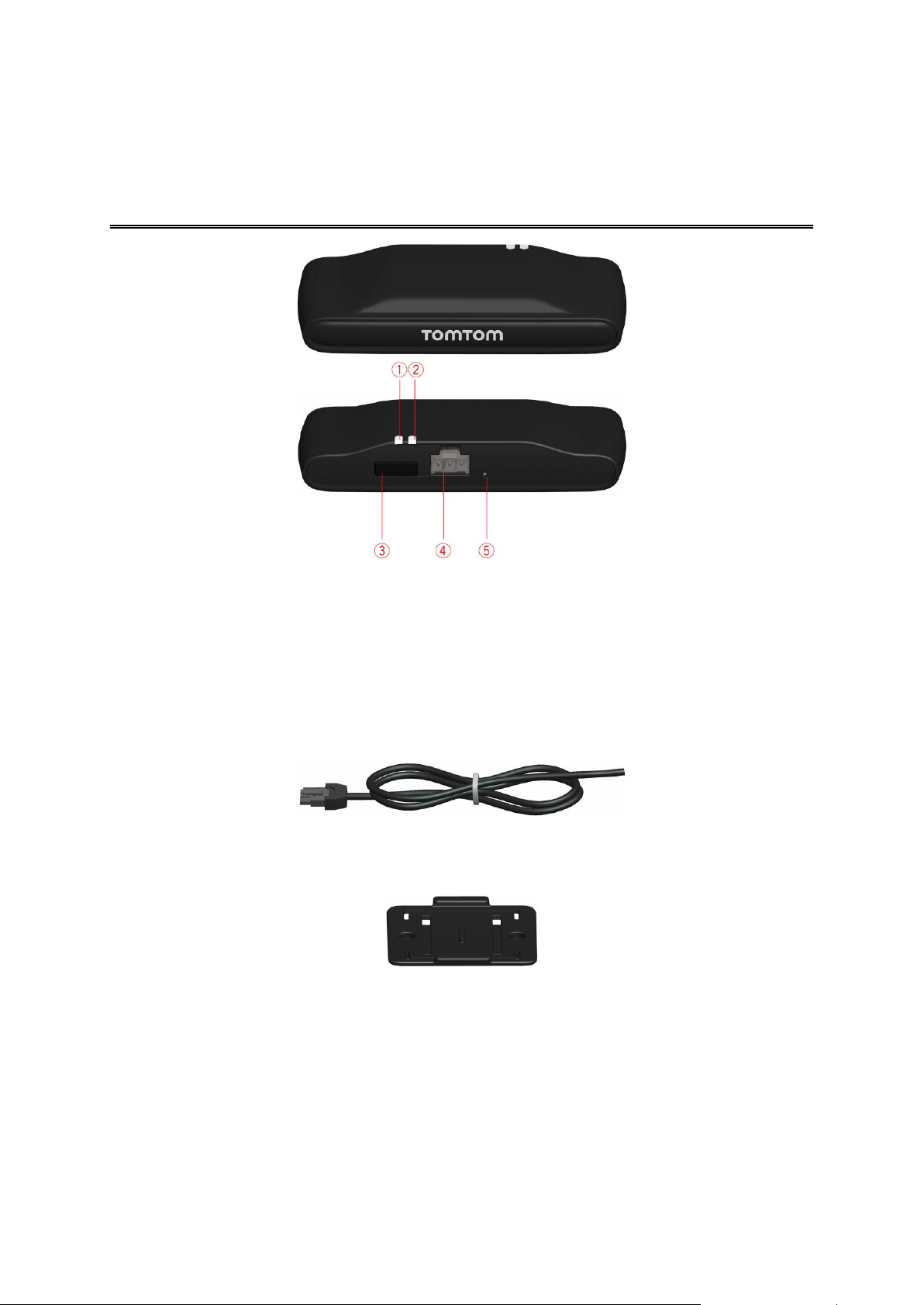
What’s in the box
1. Yellow LED - connection status indicator.
2. Green LED - system status indicator.
3. Service/Update Mini-USB-cable connector.
4. Power cable connector.
5. Reset button.
Power cable
Holder
Fixings - 2 adhesive strips and a cleaning tissue
4
Page 5

Congratulations
Read me first
You have chosen the TomTom LINK 410, a core hardware component from WEBFLEET. With
WEBFLEET from TomTom Telematics you are always connected to your people out on the road in
a smart and easy way.
TomTom LINK 410 is a GPS receiver and mobile network module in one unit, always providing the
vehicle’s current position.
When used with a compatible Driver Terminal*, you can easily handle orders, as well as text and
status messages. You can receive traffic information, and you are warned when you are driving or
cornering too fast. And you can get information about how much fuel you have used.
What you need for the installation
Before starting the installation of your TomTom LINK 410, read the installation instructions and the
safety notices and warnings carefully and make sure you have the following:
The WEBFLEET Contract Confirmation letter including the Activation Code.
All parts contained in the box.
A connection to the vehicle’s power supply that is fused with max. 10A.
A place with a clear view of the sky where you can move your vehicle to check GPS
reception.
A TomTom navigation device that is compatible with TomTom LINK 410* - optional.
* To check compatibility please visit telematics.tomtom.com/products
5
Page 6

Important safety notices and warnings
Safety first
Important: Read the following safety instructions carefully. Read the instructions in this document
carefully.
TomTom Telematics accept no liability for damage that results from disregarding the safety
instructions. This document is part of the product. Keep it in a safe place. If you pass the unit on to
a new user, make sure you give them this document as well.
Use of this product is restricted in some areas
The TomTom LINK 410 contains a mobile network module which can interfere with electrical
devices such as cardiac pacemakers, hearing aids and aviation equipment. Interference with these
devices may endanger the health or life of you or others. If your device includes a mobile network
module, do not use it near unprotected electrical units or in areas where the use of mobile
telephones is prohibited, such as hospitals and aircraft.
Danger of explosion
Parts of the TomTom LINK 410 can cause sparks that can lead to explosions. This may endanger
human health and life. Do not use the unit in areas with high risk of explosion. When using a
TomTom LINK 410 in a vehicle fuelled by liquefied gas, follow the safety regulations of the country
in which the vehicle is operated.
Damage caused through improper installation
The installation and initial operation of the unit must be performed by authorised personnel only
for example, a qualified radio dealer or an automotive electronics workshop.
Risk of injury in case of accidents
Do not mount the unit or accessories in the inflation area of airbags or in the impact area for the
head or knees. Choose an installation location that will avoid interference with displays, safety
equipment and controls.
Damage to the chassis
Make sure you do not drill into parts of the chassis that have structural or security-related
functions. This is because you cannot be certain that they will function properly after modification.
Risk of fire
Make sure you do not drill into covered wiring harnesses, fuel lines or similar components. Drilling
into these can cause fire.
6
Page 7

Repair and replacement
Repairs must be carried out by authorised and qualified personnel only. Never replace damaged
parts of the unit yourself. Send the defective unit to TomTom Telematics for repair. Only the
qualified staff of TomTom Telematics are authorised to repair or replace parts.
Damage to the device
Short-circuits inside the unit can be caused by contact with water or other liquids. The unit may be
damaged by contact with water. Use and store the unit in an area protected from water.
Risk of accidents
Do not use the digital output to cut the engine power, to remotely stop the engine or to otherwise
remotely immobilise the vehicle.
7
Page 8

We recommend updating the firmware on your LINK 410. You can do this by using the Firm-
Updating the LINK 410
ware-Update Tool and a Microsoft Windows® computer. A connection to the Internet or
WEBFLEET is not required.
System Requirements
Before you can use the LINK 410 Firmware-Update Tool, you need the following:
The TomTom LINK 410 Service Set.
A Microsoft Windows computer.
The latest LINK 410 Firmware-Update Tool (firmware is embedded).
The USB driver for TomTom LINK 410 devices.
Preparations
1. Install the USB driver.
This is required to establish a connection between your computer and your LINK 410 using the
USB cable.
You can download the USB driver from the Partner Portal. Install the driver on your computer
by double clicking the .exe file and following the instructions.
2. Install the latest Firmware-Update Tool version.
You can download the latest Firmware-Update Tool from the Partner Portal under Software
and Firmware. You must be logged in to the Partner Portal to download the Tool. The downloadable ZIP file contains the tool with the firmware update file embedded. Unzip the downloaded file to your local hard disk.
Updating the firmware on your LINK 410
To update the firmware on your LINK 410 using the Firmware Update Tool, do the following:
1. Connect your LINK 410 to a Microsoft Windows® computer using USB.
The first time you connect a LINK 410 to your computer’s USB port, a pop-up window tells you
about the installation of the hardware. Follow the instructions and select automatic installation.
A virtual COM port named TomTom LINK followed by a port number is assigned.
To find out the port number, do the following: Open the Windows Control Panel. Select the
Hardware tab. Select Device Manager. Open the list for Ports (COM & LPT).
2. Start the Firmware-Update Tool by double clicking on the .exe file.
On a computer with Microsoft Windows® Vista or Windows® 7, you must run the tool in
Windows© XP compatibility mode.
8
Page 9
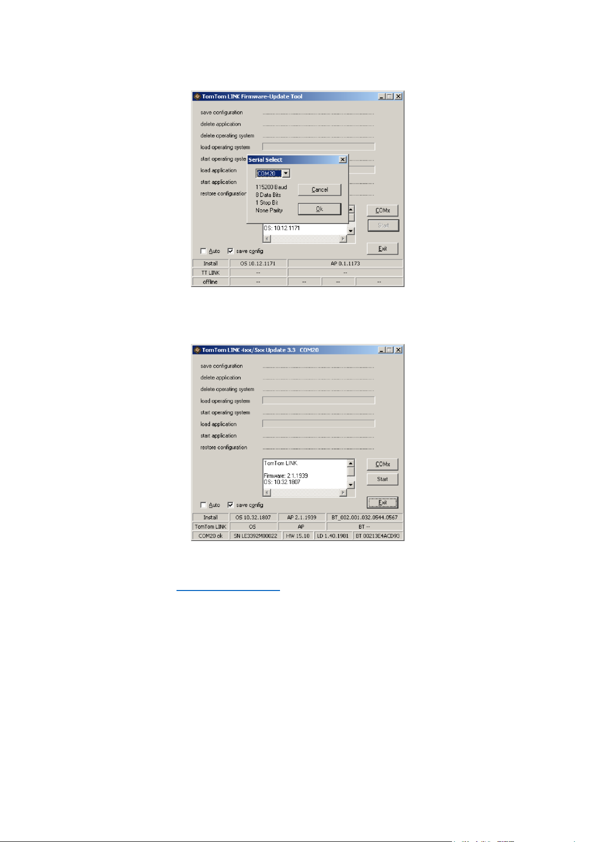
3. Select the COM port that was assigned to your LINK 410 from the list and click OK.
At the bottom of the window you can find information about the operating system installed on
the LINK 410, the serial number of the LINK 410 and which COM Port number was assigned, as
well as the operating system that will be installed with this update.
If the version number of the firmware installed on your LINK 410 is lower than the one included in the Firmware-Update Tool, continue with the next ystep. If it is up-to-date, disconnect
your LINK 410 and activate your LINK 410.
4. Select Start to initiate the firmware update installation process.
9
Page 10

The old firmware is deleted and the new firmware is installed on the device. During the installation process the upper part of the window displays the installation progress.
5. When the firmware installation is complete, click OK to confirm.
6. To close the Firmware-Update Tool click Exit.
10
Page 11

Exit closes the application. If you want to install the firmware on multiple devices, disconnect
the USB cable from the updated device and connect it to another LINK 410. The tool automatically recognises the new connection and you can repeat the installation as described above.
Using the XP Compatibility mode
If you want to use the LINK 410 Firmware-Update Tool on a computer with Microsoft Windows
Vista or Windows 7, you must run the tool in Windows XP compatibility mode as it is not
compatible with newer versions of Microsoft Windows.
To run the Firmware-Update Tool in XP compatibility mode, do the following:
1. Go to the installation folder of the Firmware-Update Tool on your computer and locate the
.exe file.
2. Right click on the .exe file and select Properties.
3. Select the Compatibility tab.
4. Select the checkbox for Run the program in compatibility mode for:.
5. Select Windows XP from the list and then click OK.
The tool can now be used on a computer with Microsoft Windows Vista or Windows 7.
11
Page 12

After you have updated your LINK 410 with the latest firmware version you need to activate the
Activating the LINK 410
LINK 410 using the TomTom LINK Activation Tool. You can also activate your LINK 410 using a
PRO navigation device.
To activate your LINK 410 using a computer you need to connect it using a USB cable. Download
the USB driver from the Partner Portal and install the driver on your computer by double clicking
the exe file.
To activate your LINK 410 do the following:
1. Install the latest version of the TomTom LINK Activation Tool.
You can download the Activation Tool from the Partner Portal at
http://telematics.tomtom.com/partners/. Go to Technical Support and select Activation and
Diagnostics.
2. Connect your LINK 410 to supply voltage.
3. Connect your LINK 410 to your computer using the Mini USB cable.
4. Start the TomTom LINK Activation Tool by double clicking the icon.
5. Click Serial Connect and select the COM port to which you have connected your LINK 410.
6. Monitor the yellow connection LED on your LINK 410 until it indicates that the device has
established a connection to WEBFLEET.
12
Page 13

When the connection to WEBFLEET has been established the Activation Tool asks you to enter
your activation code.
7. Click Activate.
8. Enter the Activation Code, which you can find in your WEBFLEET contract confirmation.
9. Click OK.
13
Page 14

The progress of the activation is shown.
You have now successfully activated your TomTom LINK 410.
14
Page 15

* Make sure this wire is fused with max. 10A.
Connection overview
15
Page 16

First you need to choose the correct position in which to install your LINK 410.
Choosing the correct position
Take the following into consideration:
Do not expose the LINK 410 to direct sunlight and/or high temperature for long periods to
ensure proper operation.
To ensure GPS reception using the integrated GPS receiver, the top of the device must not be
obstructed by metal items.
To ensure GSM/GPRS reception using the integrated GSM/GPRS antenna, the device must not
be placed on or surrounded by metal items such as the vehicle’s coachwork closer than 5 cm
(2 inches) and the top side must not be obstructed by metal items.
1. Top side of the device must not be obstructed by metal items.
2. Keep minimum distance of 5 cm (2 inches) to metal items.
16
Page 17

Connect the LINK 410 to the vehicle power supply with the standard vehicle voltage (12 V/24 V).
Connecting to power
Do not connect to a voltage converter. The three wires GND, IGN and PWR+ (supply voltage)
must be connected.
Important: Follow the order of connecting the wires as described below. First connect the wires
then insert the plug into the LINK 410.
If you have inserted the plug into the LINK 410 first, you must connect the GND wire before you
connect the PWR+ wire and the IGN wire as described below.
1. Connect the GND wire (brown) to ground (clamp 31).
2. Connect the PWR+ wire (red) to the carry current (clamp 30).
The connection must be fused with max. 10A. If not, fuse the the PWR+ wire with one 2A fast
blow fuse.
3. Connect the IGN wire (black) to ignition (clamp 15).
The connection must be fused with max. 10A. If not, fuse the the IGN wire with one 2A fast
blow fuse.
4. Insert the 3-pin plug into the power cable connector.
If you need to disconnect the wires while the 3-pin plug is plugged in the LINK 410 make sure
you disconnect the GND wire last.
17
Page 18

Your LINK 410 comes with an integrated GSM antenna and an integrated GPS antenna.
Mounting the LINK 410
The device must be positioned so that it is unobstructed by metal objects.
The device must not interfere with clear vision for the driver.
Tinted metallised windscreens or those with integrated filament heating may block GPS
reception.
Place the unit a minimum of 5 cm (2 inches) distance to the coachwork or other metal items,
so that optimal mobile network transmission and GPS reception is ensured.
The unit must be placed on an oil free, dry and clean surface, when using the adhesive strips.
Extreme temperature changes/differences can affect the adhesive property of the strips.
Before installing the device, please consider the safety instructions and choose the correct
position.
The LINK 410 can be attached with the two adhesive strips, the two tapping screws or the cable
ties.
Attaching the holder using the adhesive strips
You can use the two adhesive strips to fix the LINK 410 to your vehicle. Follow the safety
instructions in this document.
1. Choose a flat surface for accurate positioning of the unit.
Remember, when the LINK 410 is in the holder, it must not be obstructed by metal objects.
2. Clean the surface with the supplied cleaning tissue, so that the surface is oil free, dry and
clean.
3. Remove the protective film from one side of the strips.
4. Stick the strips to the bottom side of the holder as shown below.
Important: Use the strips only in combination with the holder. Do NOT place the strips on the
serial number sticker of the device.
5. Remove the protective film from the other side of both strips.
6. Place the holder with the adhesive strips on the prepared surface. Press it gently for a few
seconds until it sticks.
Note: The full strength of the strips will be reached after approximately 72 hours depending
on the temperature.
18
Page 19

7. Insert the LINK 410 into the holder. Press gently until it clicks into place.
Attaching the holder using self-tapping screws
You can use two self-tapping screws to fix the holder to your vehicle.
Please refer to the list of what's in the box, to check that the self-tapping screws (3.5 x 16 mm,
1/7 x 5/8 inches) are included in your product package.
1. Choose a flat surface for the LINK 410.
Remember, when the LINK 410 is in the holder, it must not be obstructed by metal objects.
2. Insert the two screws into the corresponding holes in the holder.
3. Tighten the screws.
4. Carefully place the LINK 410 in the holder until it clicks into place.
Attaching the holder using cable ties
You can use two cable ties to fix the holder to your vehicle. Using cable ties might have an impact
on the accuracy of the driving event reporting if the device is not fixed properly.
Please refer to the list of what's in the box, to check that the cable ties (205 x 3.5 mm, 8 x 1/7
inches) are included in your product package.
1. Choose a position where the LINK 410 is not obstructed by metal objects when it is in the
holder.
2. Insert the cable ties into the corresponding holes in the holder.
3. Wrap the cable ties around the object where you want to place the holder.
4. Pull the cable ties through the corresponding holes of the holder and insert them in the noose
at the other end of the cable ties.
19
Page 20

5. Pull the cable ties tight so that the holder cannot move.
6. Insert the LINK 410 into the holder. Press gently until it clicks into place.
20
Page 21

In addition to the tests described below you can also test the operation of your LINK 410 using the
Testing operation
TomTom Telematics Diagnostic Tool with Bluetooth.
Power or Ignition test
Before testing the connection to power and to the ignition make sure you have properly carried
out the installation.
1. Check all connections to your LINK 410 device (wires, fuses etc.).
2. Turn off the ignition.
The green LED should be off and then go on every 3 seconds.
3. Turn on the ignition.
The green LED should be on and then go off every 3 seconds. If the device is already activat-
ed, the green LED should be on all the time.
If the LED does not perform as described, monitor the LEDs for diagnostics .
Mobile network reception test
For this test, you may need to move the vehicle to a location with a clear view of the sky, to make
sure that you have adequate GPS and mobile network reception.
For this test put your LINK 410 device in the position where you want to fix it.
1. Turn on the ignition.
2. Look at the yellow LED. It should be on and then go off every 3 seconds.
As soon as the device has established a connection to WEBFLEET the yellow LED stays on all the
time.
If the LED keeps flashing for longer than 10 minutes, monitor the LEDs for diagnostics .
21
Page 22

Connect your PRO Driver Terminal to your LINK 410 to fully enjoy the benefits of your WEBFLEET
Connecting to PRO and WEBFLEET
solution.
To use a Driver Terminal in combination with the LINK 410 a corresponding WEBFLEET
subscription is required.
When you first switch on your Driver Terminal, you are asked to connect it with the LINK 410
installed in your vehicle. You can do this immediately or at any time later by doing the following:
1. Make sure that the LINK 410 is connected to power and has a mobile network connection.
2. Switch on your PRO Driver Terminal.
3. Tap the Main Menu button in the lower left corner.
Note: If you have a PRO 51xx/71xx tap the screen to bring up the Main Menu.
4. Tap WEBFLEET.
Note: If you have a PRO 51xx/71xx tap WORK.
You are asked to start the activation process. After you have started the activation process
your Driver Terminal starts searching for Bluetooth devices.
If your Driver Terminal finds more than one Bluetooth device, it shows a list of the available
devices. Continue with step 5.
If your Driver Terminal finds only one LINK 410, continue with step 6.
5. Select your LINK 410 from the list.
The name starts with LINK followed by the serial number of your LINK 410 or the licence plate
number of your vehicle. You can find the serial number on the outside of your LINK 410.
6. Enter the Activation Code, which you can find in your WEBFLEET contract confirmation.
Select the appropriate subscription from the list, if there are several subscriptions to choose
from. Enter a name for your LINK 410 if you are asked to do so.
Note: If you have a PRO 51xx/71xx you are asked to enter the licence plate number of the
vehicle and to select the appropriate vehicle type. If you select Truck or Bus, you have to enter
your vehicle dimensions.
If you have properly connected the two devices, you receive a welcome message from WEBFLEET
confirming the activation. In future the connection is established automatically.
To check the connection status between the two devices, bring up the Main Menu. Then tap
Settings, then tap Help and select WEBFLEET connection status from the list.
Note: If you have a PRO 51xx/71xx, check the connection status between the two devices by
tapping WORK in the Main Menu, then tap Connection status.
22
Page 23

Monitoring operation
GREEN LED mode
OFF
Unit is in standby mode or is not connected to power.
Switch on ignition.
Check if the device is properly connected to power.
OFF and short ON
every 3sec
Ignition off.
Rapidly flashing
No operating system and/or no application available or application
failed.
Install latest firmware application using the TomTom Telematics
Firmware Update Tool.
ON and short OFF
every 3sec
Ignition on. Application is running, device is not activated.
Activate device.
ON
Application is running, device is activated.
YELLOW LED mode
OFF
Not connected - No mobile network coverage.
Check if device is connected to power. Switch on ignition.
Move the vehicle as you may be in a mobile network dead spot.
OFF and short ON
every 3sec
Not connected - Correct mobile network operator not avaialable.
Check WEBFLEET subscription for mobile network roaming support.
Move the vehicle as you may be in a mobile network dead spot.
Rapidly flashing
SIM not in place; SIM defective; Modem problem.
Use TomTom Telematics Diagnostics Tool for detailed diagnostics
and contact TomTom Telematics Customer support at telemat-
ics.tomtom.com/support. Enclose the log file provided by the Diag-
nostics Tool.
ON and short OFF
Connecting. No mobile network available.
Diagnostics
You can monitor the system operation of your LINK 410 by looking at the green system LED and
referring to the table below.
For detailed diagnostics use the TomTom Telematics Diagnostic Tool. You can download the
Diagnostic Tool from the Partner Portal at telematics.tomtom.com/10001/areas/reseller/index.xml
Go to Technical Support and select Activation and Diagnostics.
You can monitor the connection of your LINK 410 to the mobile network and to WEBFLEET by
looking at the yellow connection LED and referring to the table below. For detailed diagnostics
always use the TomTom Telematics Diagnostics Tool.
23
Page 24

every 3sec
Move the vehicle as you may be in a mobile network dead spot.
ON
Connected.
Support
If you cannot find the answer to your question with the help of the tables above, please contact
the TomTom Telematics support team at telematics.tomtom.com/support.
24
Page 25

If your LINK 410 does not operate properly or signals a system error you may need to restart or
Resetting the LINK 410
reset the unit. Only restart or reset the LINK 410 after you have made sure you have carried out all
previously described steps without success.
Restarting your LINK
To restart your LINK 410, press the reset button with a thin pointed object until it clicks and keep it
pressed down for 1 to 2 seconds. The LINK 410 restarts immediately after releasing the button.
If restarting the device does not succeed remove the power cable from the LINK 410. Then plug it
into the power cable connector again.
Resetting your LINK to factory settings
To reset the LINK 410 to factory settings, press the reset button with a thin pointed object until it
clicks and keep it pressed for 8 seconds. The LINK 410 reboots immediately after releasing the
reset button. You can count the seconds with the help of the flashing of the green LED, that
flashes once per second.
Important: All information stored on the LINK 410 is deleted during a factory reset.
If resetting the device does not succeed, do the following:
1. Remove the power cable from the device.
2. Press the reset button with a thin pointed object until it clicks and keep it pressed.
3. Insert the power cable while keeping the reset button pressed for 8 seconds.
You can count the seconds with the help of the flashing of the green LED, that flashes once
per second.
The LINK 410 reboots immediately after releasing the reset button.
25
Page 26

Dimensions
Body: 121 x 56.5 x 21.5 mm / 4.76 x 2.22 x 0.85 inches
Body with Holder: 121 x 68 x 25.5 mm / 4.76 x 2.68 x 1.00 inches
Weight
Body: 84 g / 3 ounces
Holder: 12 g / 0.5 ounces
Material
Body and holder: Injection moulded plastic PC/ABS
Protection class
IP 30
Supply voltage
12 V / 24 V (min. 9 V to max. 30 V)
Current / power
consumption
(average values)
At 14 V: typically < 0.05 A / < 0.7 W
At 28 V: typically < 0.03 A / < 0.84 W
Standby: typically < 0.001 A / < 0.03 W
During data transmission
14 V < 0.15 A / < 2.1 W
28 V < 0.1 A < 2.8 W
Fuse protection
Operating voltage* 9 - 30 V to be fused with max. 10A
Ignition to be fused with max. 10A
* Internally fused with 2A, fuse is not resettable or replaceable, fuse must
be replaced by TomTom Telematics only
Temperature
Operation: -30 °C to +70 °C / -22 °F to +158 °F
Storage: -40 °C to +80 °C / -40 °F to +176 °F
Mobile networks
Integrated mobile network module intended for connection to one or
more of the following mobile network frequencies:
800/850/900/1800/1900/2100 MHz
GPS
Integrated GPS antenna and GPS receiver
BluetoothTM
Integrated BluetoothTM (class 2) for connection to navigation device
Ignition input
To be connected to the ignition clamp to switch on/off device together
with ignition
Primary battery
3 V non-rechargeable, this device cannot be operated with this battery
Technical data
26
Page 27

CE marking
Addendum
The unit described in this document is in accordance with the official European directives. A copy
of the declaration of conformity can be provided on request. This equipment complies with the
essential requirements of EU Directive 99/5/EC. The GPRS-modem integrated in this product has
been pre-certified separately and is marked with CE0168.
WEEE directive
The wheelie bin symbol on the product or its packaging indicates that this product shall not be
treated as household waste. In line with EU Directive 2012/19/EU for waste electrical and
electronic equipment (WEEE), this electrical product must not be disposed of as unsorted
municipal waste. Please dispose of this product by returning it to the point of sale or to your local
municipal collection point for recycling. By doing this you will help conserve the environment.
Exposure limits
This device complies with radiation exposure limits set forth for an uncontrolled environment. In
order to avoid the possibility of exceeding the radio frequency exposure limits, human proximity
to the antenna shall not be less than 20cm (8 inches) during normal operation.
Mobile networks
Devices that contain a mobile network module are intended for connection to one or more of the
following mobile network frequencies:
800/850/900/1800/1900/2100 MHz
Notice for New Zealand
This product displays R-NZ to show it complies with relevant New Zealand regulations.
This document
Great care was taken in preparing this document. Constant product development may mean that
some information is not entirely up to date. The information in this document is subject to change
without notice.
27
Page 28

TomTom shall not be liable for technical or editorial errors or omissions contained herein, nor for
incidental or consequential damages resulting from the performance or use of this document. This
document contains information protected by copyright. No part of this document may be
photocopied or reproduced in any form without prior written consent from TomTom N.V.
Copyright notices
© 2016 TomTom. All rights reserved. TomTom and the "two hands" logo are registered trademarks of TomTom N.V. or one of its subsidiaries. Please see tomtom.com/legal for limited
warranty and end user licence agreements applying to this product.
28
 Loading...