

Page 1

TomTom LINK 300/310 Installation Guide
EN
DE
FR
NL
IT
ES
PT
DA
SV
PL
CS
English 4
Deutsch 30
Français 56
Nederlands 82
Italiano 108
Español 134
Português 160
Danske 186
Svenska 212
Polska 238
České 264
Page 2
EN
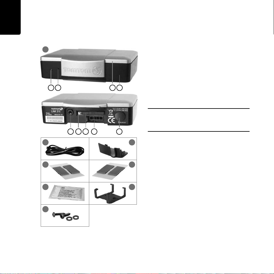
What’s in the box
1
C G
F I H D E
2
A B
What’s in the
box
a TomTom LINK 300/310
A Top side
B Bottom side
C LED
D Power cable connector
E GPS antenna connector (SMB) for
optional use of an external GPS antenna
F Service/Update cable connector
G Reset button
H SIM card holder
I Release button for SIM card holder
Important: Do not remove the SIM card from the
TomTom LINK 310. Only use the SIM card provided
in the TomTom LINK 310. Other SIM cards may
damage the LINK device.
b Power cable
3
c Plastic seal
4
d Two adhesive strips (transparent, for
5
windscreen mounting)
e Two adhesive strips (grey, for dashboard
mounting)
6
7
f Cleaning tissue
g Holder
8
h Two self-tapping screws and washers
4
Page 3

Before the Installation
Congratulations
You have chosen the TomTom LINK 300/310,
a core hardware component of TomTom
WORKsmart fleet management solutions.
With WORKsmart from TomTom Business
Solutions you are always connected to your
people on the road in a smart and easy way.
TomTom LINK 300/310 is a GPS receiver and
GSM/GPRS module in one unit, always
providing the vehicle’s current position. When
used with a compatible TomTom navigation
device*, you will be able to easily handle
orders, as well as text and status messages.
Before the Installation
What you need for the installation
Before starting the installation of your
TomTom LINK 300/310, read the safety
notices and warnings carefully and make sure
you have the following things:
•The TomTom WEBFLEET Contract
Confirmation letter including the
Activation Code and the SIM Card*.
• All parts mentioned in the chapter What’s
in the box on page 4 and two 2 A / fast
blow fuses (not included in the box).
•A place with clear view of the sky where
you can move your vehicle to check GPS
reception.
•A TomTom navigation device that is
compatible to TomTom LINK 300/310**.
* SIM Card are sent separately only for TomTom
LINK 300.
** Compatible devices to the LINK 300/310:
TomTom GO 7000 or any device of the PRO 7xxx
series
EN
5
Page 4

EN
Safety first
Safety
first
Important safety notices and warnings
Important: Read the following safety
instructions carefully
TomTom Business Solutions accept no
liability for damage that results from disregard
for the safety instructions.
This document is part of the product. Keep it in
a safe place. If you pass the unit on to a new
user, make sure you give them this document
as well.
• Important - damage caused through
improper installation
The installation and initial operation of the
unit must be performed by authorised
personnel only, e.g. a qualified radio dealer
or an automotive electronics workshop.
Consider the quality standards of the motor
vehicle trade.
• Caution - risk of injury in case of accidents
Do not mount the unit or accessories in the
inflation area of airbags or in the impact
area of the head or knees. Search carefully
for an installation location that will avoid
interference with displays, safety
equipment and controls.
• Caution - damage to the chassis
Make sure you do not drill into parts of the
chassis that have structural or securityrelated functions. You cannot be certain
that they will function properly after
modification.
• Caution - risk of fire
Make sure you do not drill into covered
wiring harnesses, fuel lines or similar
components. Drilling into these can cause
fire.
• Caution - use of this product is restricted
in some areas
The GSM module of the TomTom LINK
300/310 is likely to interfere with electric
devices such as cardiac pacemakers,
hearing aids, electric devices used in
intensive medicine, and aviation
equipment. The interference with these
devices can endanger the health or life of
the users. Do not use near unprotected
electrical units nor in areas where the use
of mobile telephones is prohibited, such as
hospitals and airplanes! Switch off the unit
if there is a danger of interference with such
equipment.
6
Page 5

• Caution - danger of explosion
Parts of TomTom LINK 300/310 can cause
sparks, which can lead to explosions. This
may endanger human health and life. Do
not use the unit in areas with high risk of
explosion. When using TomTom LINK 300/
310 in a vehicle fueled by liquefied gas,
follow the safety regulations of the country
in which the vehicle is operated.
• Warning - repair and replacement
Repairs must be carried out by authorised
and qualified personnel only. Never replace
damaged parts of the unit yourself. Give
the defective unit to TomTom Business
Solutions. Only the qualified staff of
TomTom Business Solutions are
authorised to repair or replace parts.
• Warning - damage to the device
Short-circuits inside the unit can be caused
by contact with water or other liquids. The
unit may be damaged by contact with
water. Use and store the unit in an area
protected from water.
• Caution - risk of accidents
Using the unit while driving is distracting
and can cause accidents. To ensure road
safety, only enter information in the unit
when the vehicle is not being driven.
EN
Safety first
7
Page 6

EN
Find the right Place
Find the
right
Place
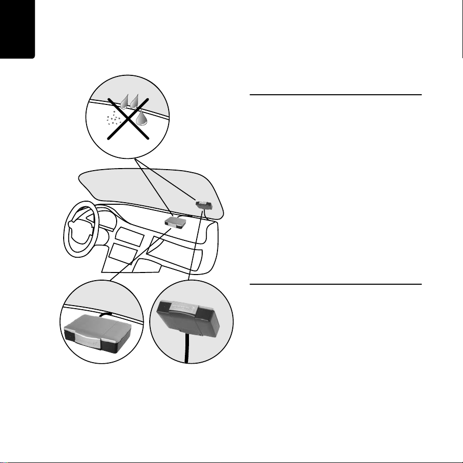
First you need to find the right place to install
your LINK 300/310. You can either decide for a
hidden or for a non hidden installation.
If you are using the LINK 300/310 together with
a TomTom navigation device, then keep a
distance bigger than 30 cm between the two
devices to ensure optimal operation.
Hidden installation
If you prefer to keep the LINK 300/310 in a
hidden place, to protect it from high
temperatures or for safety reasons (to not
obstruct the driver’s view e.g. in the
windscreen) you can place the device beneath
the dashboard e.g. in the glove compartment.
Non hidden installation
If you do not want to use an external GPS
antenna and always have free access to the
device you can simply affix it to the dashboard
or to the windscreen of your vehicle. (see
Mounting LINK 300/310 on page 14)
If the vehicle is often parked for longer periods
exposed to direct sunlight and/or to high
outside temperature, without the utilisation of
an aircondition, the device might not work
properly. In those cases TomTom Business
Solutions recommends a hidden installation.
For this you need to find a place where the top
side of the device is not obstructed by metal
items. Also, you need the external GPS
antenna (see Alternative Mounting on
page 21). Use only the external GPS antenna
from TomTom Business Solutions. This is an
optional accessory which is not included in the
box.
8
Page 7

Find the right Place
EN
9
Page 8

EN
GPS
Connection overview
Connection
overview
TomTom GO 7000
TomTom PRO 7xxx
Bluetooth
TomTom LINK 300/310
TM
GPS Antenna
MB
SMB
Antenna
F1 2Af*
(red)
(brown)
F2 2Af*
(black)
F3 2Af*
* See Technical data on page 27
** Make sure this wire is fused with 15 A.
IGN
10
+9-30VClamp 30**
GNDClamp 31
(+9-30V)Clamp 15**
Power Cable
IN 1+9-30V (green/blue)
Optional
Page 9

For the transmission process
The following instructions apply for the LINK 300
only. The LINK 310 already comes with a built-in SIM
card.
To prepare the LINK 300 for data exchange
with TomTom WEBFLEET you need to insert
the SIM Card in the unit.
1. Press the release button for the SIM Card
holder with a pointed object until it
releases.
2. Pull out the SIM card holder.
3. Gently press the SIM card into the SIM card
holder until it clicks into place.
4. Hold the SIM card holder with the SIM card
facing down, then insert the holder into
LINK 300 as shown in the figure.
Insert the SIM
Card
EN
Insert the SIM Card
11
Page 10

EN
Connecting to power
Connecting to
power
Connect LINK 300/310 to the vehicle power
supply with the standard vehicle voltage (12 V
/ 24 V). Do not connect to a voltage converter.
The three wires GND, IGN and PWR+ (supply
voltage) must be connected.
1. Connect the GND wire (brown) to ground
(clamp 31).
2. Fuse the PWR+ wire (red) and the IGN wire
(black) with one 2 A / fast blow fuse
(Technical data on page 27) each.
3. Connect the fused PWR+ wire (red) to the
carry current (clamp 30).
4. Then connect the fused IGN wire (black) to
ignition (clamp 15).
5. The IN1 wire can be used for multiple
purposes, e.g. connecting a digital
tachograph, reporting idle times or
recording other digital inputs. See Using
the digital input on page 19 for details. If
you do not make use of the input IN1,
please connect the IN1 wire (green/blue) to
GND.
6. Insert the 4-pin plug into the power cable
connector.
12
Page 11

Testing operation
Power/Ignition test
Before testing the connection to power and to
ignition make sure you have carried out the
steps described in the previous chapters.
1. Please check all connections to LINK 300/
310 (wires, fuses etc.).
2. Turn on the ignition. The LED must be on
with occasional (100ms) periods off.
3. Turn off the ignition. The LED must now be
off with occasional (100ms) periods on.
If the LED does not perform accordingly see
Diagnostics on page 24.
EN
Testing operation
GPRS / GPS reception test
For this test, you may need to move the
vehicle to a location with a clear view of the
sky, to make sure that you have adequate GPS
and GPRS reception.
For this test put the LINK 300/310 into the
place where you want to affix it (please see
Mounting LINK 300/310 on page 14).
1. Turn on the ignition.
2. Monitor the LED. It must be on with
occasional (100ms) periods off.
3. Please wait until the LED stops flashing.
If the LED keeps flashing longer than 10 min see
Diagnostics on page 24.
13
Page 12
EN
OIL
Mounting LINK 300/310
OIL
Mounting LINK
300/310
Your LINK 300/310 comes with an integrated
GSM antenna and an integrated GPS antenna.
• LINK 300/310 must be placed unobstructed
by metal objects and with the top side
having clear view of the sky.
• The device must not interfere with clear
vision for the driver.
• Tinted metallised windscreens or those
with integrated filament heating may
obstruct GPS reception.
• Place the unit on the dashboard or on the
windscreen with min. 5 cm distance to the
coachwork, so that optimal GSM
transmission and GPS reception is
ensured.
• The unit must be placed on an oil free, dry
and clean surface. Extreme temperature
changes/differences can affect the
adhesive property of the strips.
• Optimally find a place with a distance
bigger than 30cm to the TomTom
navigation device.
The LINK 300/310 can be affixed to the
windscreen or the dashboard with the two
adhesive strips. For information about a
hidden installation such as in the glove
compartment, see Alternative Mounting on
page 21.
Use the two adhesive strips to affix LINK 300/
310 to the dashboard (grey strips) or the
windscreen (transparent strips). Follow the
safety instructions in this document.
14
Page 13

1. Choose a flat surface for accurate
positioning of the unit.
2. Clean the surface with the provided
cleaning tissue, so that the surface is oil
free, dry and clean.
3. Remove the protective film from one side
of the strips.
4. For dashboard mounting (see figure) stick
the strips to the bottom side. For
windscreen mounting stick the strips to the
top side.
5. Remove the protective films from the other
side of both strips.
6. Place the unit with the adhesive strips on
the prepared surface. Press it gently for a
few seconds until it sticks.
Note: The full strength of the strips will be reached
after approx. 72 hours depending on the
temperature.
EN
Mounting LINK 300/310
15
Page 14

EN
Connecting to GO/PRO and WEBFLEET
Connecting to
GO/PRO
and
WEB-
Connect your navigation device to your LINK
FLEET
300/310 to fully enjoy the benefits of your
WORKsmart solution.
When you first switch on your navigation
device, you are asked to connect it with the
LINK 300/310 installed in your vehicle. You can
do this immediately or at any time later.
1. Make sure that the LINK 300/310 is
connected to power and has a GPRS
connection.
2. Switch on your navigation device.
3. Tap the screen to bring up the Main Menu.
4. Tap WORK.
You are asked to start the activation
process. After you have started the
activation process your navigation device
starts searching for Bluetooth devices.
If your navigation device finds more than
one Bluetooth device, it shows a list of the
available devices. Continue with step 5.
If your navigation device finds only one
LINK 300/310, continue with step 6.
5. Select your LINK 300/310 from the list.
The name starts with LINK followed by the
serial number of your LINK 300/310 or the
license plate number of your vehicle. You
can find the serial number on the outside of
your LINK 300/310.
6. Enter the Activation Code, which you find
in your WEBFLEET contract confirmation.
16
Page 15

Connecting to GO/PRO and WEBFLEET
EN
7. Enter the licence plate number of the
vehicle.
8. Select the appropriate vehicle type.
If you select Truck or Bus, you have to enter
your vehicle dimensions.
If you have properly connected the two
devices, you will receive a welcome message
from WEBFLEET confirming the activation. In
future the connection is established
automatically.
To check the connection status between the
two devices, tap Settings in the WORK menu
on your navigation device, then tap
Connection status.
17
Page 16

EN
Closing the LINK 300/310
Closing the
LINK 300/310
After you have successfully tested the
operation of the LINK 300/310 (see Testing
operation on page 13) and connected to the
TomTom navigation device and TomTom
WEBFLEET (see Connecting to GO/PRO and
WEBFLEET on page 16), you can now close
the LINK 300/310 with the plastic seal.
IMPORTANT: Once you have closed the LINK 300/
310 with the plastic seal, the device cannot be
opened again without damaging the seal.
For this, slide the plastic seal over the plug of
the power cable into the housing and press
gently until it engages.
18
Page 17
Using the digit-
GND
Tachograph
15
26
37
48
C
15
26
37
4
8
D
15
26
37
48
B
15
26
37
48
A
LINK 300/310
IN 1 GND
al input
The input IN 1 can be used for reading
information from a digital tachograph,
recording digital inputs e.g. for a digital
logbook with the help of a switch, and much
more. In TomTom WEBLEET you can select to
use the input either for a logbook or for other
digital input.
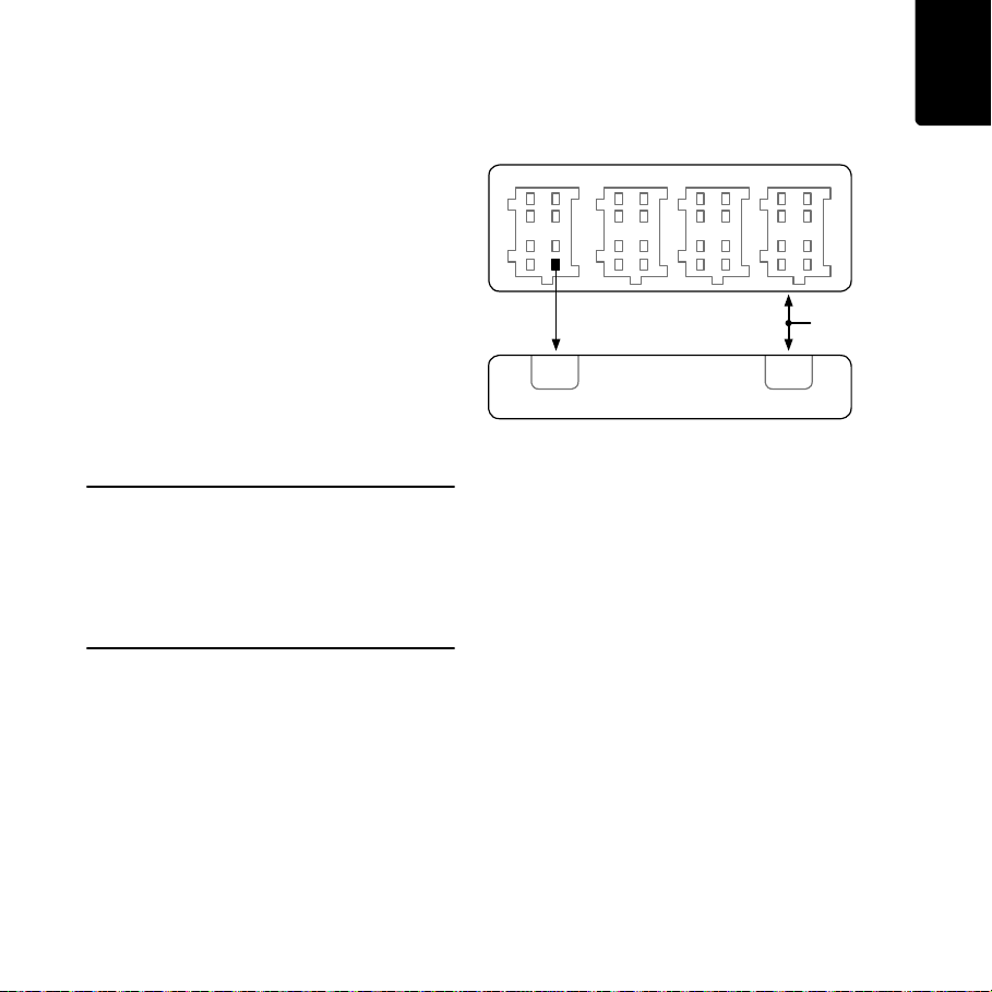
Connecting to digital tachograph
You can collect the time spent driving, resting
and working from a digital tachograph by
connecting it to your LINK 300/310 via the
digital input IN 1. Connect the input IN 1 of the
LINK 300/310 to PIN D 8 of the digital
tachograph.
Important!
Make sure that the ground potential of the LINK 300/
310 is identical to the gound potential of the digital
tachograph.
If the tachograph with the covered connectors is
sealed, the seal must only be removed by an
authorised tachograph installer.
EN
Using the digital input
Using the input for idle time reporting
LINK 300/310 can report idle times to
WEBFLEET when the engine is running for
longer than five minutes and the vehicle is not
moving. This requires configuration in
TomTom WEBFLEET.
The input IN 1 must be connected to a signal
indicating the activity of the engine, e.g.
alternator, engine, etc. The input IN 1must be
active when the engine is running. See section
“Wiring the input” for detailed information on
how to connect the relevant signal to IN 1.
Wiring the input
The Input IN 1 of the LINK 300/310 operates
according to the principle of a voltage
detector. Voltages below 2 Volts are
definitively interpreted as being low and
voltages higher than 3 Volts are definitively
interpreted as being high. The maximum
19
Page 18

EN
IN 1
(LINK 300/310)
+9 ... 30V
IN 1
(LINK 300/310)
+9 ... 30V
GND
Load resistor ≤ 10 KOhm
IN 1
(LINK 300/310)
+9 ... 30V
GND
Load resistor ≤ 10 KOhm
IN 1
(LINK 300/310)
+9 ... 30V
GND
Using the digital input
permissible input voltage is 30 Volts. Low/high
switching (increasing input voltage) typically
occurs at 2.8 Volts. High/low switching
(decreasing input voltage) typically occurs at
2.1 Volts. The hysteresis of 0.7 Volts is to avoid
rapid switching.
Interference voltages at the input IN 1 must
remain below 2 Volts. In order to guarantee
this, the input wire of the connecting cable
should never remain unconnected. If the input
IN 1 is not being used, the input wire must be
connected to ground (GND). To evaluate a
switch, this switch needs to be designed as a
change-over switch, switching input IN 1
between plus and minus (ground GND) of the
vehicle electrical system voltage (+9 ... 30V).
If no change-over switch is available, an
electric load (e.g. indicator light, resistor)
between input IN 1 and ground (GND) or
between input IN 1 and the vehicle voltage (+9
... 30V) can offer defined levels.
When using inductive loads, a free-wheeling
diode must be used in parallel with the load.
For more information and examples see http:/
/business.tomtom.com/in1
20
Page 19

Alternative
Mounting
Using the holder
You can also choose to mount the LINK 300/
310 using the holder. The holder can be
affixed either with the the two self-tapping
screws or with the adhesive strips. To use the
self-tapping screws, see the description
below. To use the adhesive strips please, see
Mounting LINK 300/310 on page 14. Follow
the safety instructions in this document.
1. Choose a flat surface for LINK 300/310.
Remember, when LINK 300/310 is in the
holder, it must have a clear view of the sky.
2. Insert the two screws into the
corresponding holes in the holder.
3. Tighten the screws.
4. Carefully place the LINK 300/310 in the
holder until it clicks into place.
EN
Alternative Mounting
21
Page 20

EN
Alternative Mounting
Mounting external GPS antenna
If you install the LINK 300/310 in a place where
it is not visible, so that it does not have a clear
view of the sky, you need to use the external
GPS antenna accessory (part number
9L09.001) from TomTom Business Solutions
which comes with an integrated magnet and
an adhesive pad. The external GPS antenna
from TomTom Business Solutions is not part
of the standard LINK 300/310 product
package.
Important!
• Only use the GPS antenna from TomTom
Business Solutions, else GPS performance
will be bad or not work at all.
• Tinted metallised windscreens or those
with integrated filament heating may
prevent good GPS reception. In this case,
place the GPS antenna in the rear window
or on the outside of the vehicle.
• The magnet of the antenna will remain
attached to the outside of the car at speeds
of up to 180 km/h.
• Install the GPS antenna in a place where it
has a clear view of the sky and is
unobstructed by metal objects.
• The GPS antenna must be placed with the
adhesive pad on an oil free, dry and clean
surface.
•Extreme temperature changes / differences
can affect the adhesive property of the pad.
• To grant GSM/GPRS reception choose a
place where the top side of the LINK 300/
310 is unobstructed by metal objects.
22
Page 21

1. Remove the rubber cap from the GPS
OILOIL
antenna connector.
2. Insert the plug of the GPS antenna into the
GPS antenna connector on the LINK 300/
310.
3. Prepare a smooth, clean, oil free and dry
surface in the windscreen.
4. Attach the antenna to the prepared surface
so that the top side has clear view of the
sky. Either locate a smooth metal surface or
use the extra adhesive pad.
EN
Alternative Mounting
23
Page 22

EN
Diagnostics
Diagnostics
Monitoring operation
Monitor the operation of LINK 300/310 according to the table below.
LED mode
OFF Unit is in Standby mode
1sec on, 100ms off, 100ms on,
100ms off
1sec on, 100ms off Waiting for GPS
ON Normal operation (GPS and GPRS are available)
4sec off, 100ms on Ignition is off (unit is not yet in Standby mode)
Rapidly flashing: 500ms on,
500ms off
Troubleshooting
Find solutions for malfunctions with the help of the LED and the table below.
Waiting for GPRS
System error (see Reset LINK 300/310 on page 26)
LED is active when ignition is
turned on and is off when ignition
is turned off
LED is off when ignition is either
turned on or off
LED is neither constantly off nor off
with occasional periods (100ms) on
when ignition is turned off
LED shows that the device is
waiting for GPRS for longer than 10
minutes after turning on the
ignition
PWR+ wire is connected to ignition and the IGN wire
is connected to power (see Connecting to power on
page 12)
Unit is not connected to the power supply (see
Connecting to power on page 12)
IGN wire and the PWR+ wire are both connected to
power. (see Connecting to power on page 12)
GSM reception may be obstructed by metal objects
(see Mounting LINK 300/310 on page 14)
24
Page 23

Diagnostics
EN
LED is 1sec on, 100ms off for
longer than 10 minutes after
turning on the ignition
Support
If you cannot find the answer to your question with the help of the tables above, please contact
the TomTom Business Solutions support team under http://business.tomtom.com/support.
GPS reception may be obstructed, check whether you
have clear view of the sky
GPS antenna might not be connected properly (in
case of a hidden installation), check the connection to
the external GPS antenna and its position. It must be
the original TomTom Business Solutions GPS
antenna. (see Alternative Mounting on page 21)
25
Page 24

EN
Reset LINK 300/310
Reset LINK
300/310
If the LINK 300/310 does not operate properly
or signals a system error (see Diagnostics on
page 24) you may need to reset the unit. Only
reset the LINK 300/310 after you have made
sure you have carried out all previously
described steps without success.
To reset the LINK 300/310 press the reset
button with a thin pointed object until it clicks
and keep it pressed for 5 seconds. The unit
reboots immediately after releasing the reset
button.
26
Page 25

Technical data
Technical data
Dimensions Body: 85 x 67 x 24 mm / Holder: 55 x 66 x 30 mm
Weight Body: 95 g / Holder: 10 g
Material Body and holder: Injection moulded plastic PC/ABS
Protection class IP 20
Supply voltage 12 V / 24 V (min. 9 V to max. 30 V)
Current consumption
(average values)
Fuse protection Operating voltage 9 - 30 V with 2 A / fast blow fuse*
Temperature Operation: -30 °C to +70 °C
GSM Integrated GSM antenna and GSM module
GPS Integrated GPS antenna and GPS receiver
Bluetooth
Ignition input To be connected to the ignition clamp to switch on/off device together with
Digital input 1 input switchable to supply voltage
GPS antenna
connector for
external GPS antenna
(optional accessory)
TM
At 14 V: typically < 50 mA
At 28 V: typically < 30 mA
Standby: typically < 1 mA
During data transmission
14V < 180mA
28V < 100mA
Ignition with 2 A / fast blow fuse*
* Mini Fuse Fast-Acting 2A (manufacturer Littelfuse, Part No. 297 002) and
Mini Fuse Easy-Crimp In-Line Fuseholder (manufacturer Littelfuse, Part No.
153002)
Storage: -40 °C to +80 °C
Dualband GSM 900/1800
Integrated BluetoothTM (class 2) for connection to navigation device
ignition
SMB (male) - (antenna - female)
Supply voltage range 3 V to 5 V
Minimum antenna gain at 3 V: 20 dB
Maximum antenna gain: 40 dB
Maximum noise rating: 1.5 dB
EN
27
Page 26

EN
Addendum
Addendum
CE-Declaration of Conformity
The unit described in this
document is in accordance with
the official European directives. A
copy of the declaration of
request. This equipment complies with the
essential requirements of EU Directive 99/5/
EC. The GPRS-modem integrated in this
product has been pre-certified separately and
is marked with CE0681.
WEEE Directive
it to the point of sale or to your local municipal
collection point for recycling.
ICASA - Declaration of Conformity
This product displays the ICASA logo to show
it complies with all relevant South African
radio equipment certifications.
conformity can be provided on
In line with EU Directive 2002/96/EC
for waste electrical and electronic
equipment (WEEE), this electrical
product must not be disposed of as
unsorted municipal waste. Please
dispose of this product by returning
Exposure limits
This device complies with radiation exposure
limits set forth for an uncontrolled
environment. In order to avoid the possibility
of exceeding the radio frequency exposure
limits, human proximity to the antenna shall
not be less than 20cm (8 inches) during normal
operation.
A-tick
N14644
The TomTom LINK 310 product
displays the A-tick to show it
complies with relevant Australian regulations.
Warning for Australia
The user needs to switch off the device when
exposed to areas with potentially explosive
atmospheres such as petrol stations, chemical
storage depots and blasting operations.
Customer Support contact
Australia: 1300135 604
Legal Information
©2011 TomTom N.V., The Netherlands.
TomTom®, The “two hands”® logo, among
others, are Trademarks owsened by TomTom
N.V. or one of its subsidiaries. Our End User
License Agreement and limited warranty
apply to this product. You can review it at
www.tomtom.com/legal
28
Page 27

TomTom
LINK
300/310
Installation
Guide
Page 28

DE
Packungsinhalt
1
C G
F I H D E
2
A B
Packungsinhalt
a TomTom LINK 300/310
A Oberseite
B Unterseite
C LED
D Anschluss für Spannungsversorgung
E GPS-Antennenbuchse (SMB) zur
optionalen Verwendung einer externen
GPS-Antenne
F Service/Update-Anschluss
G Reset-Taste
H SIM-Kartenhalter
I Auswurfknopf für SIM-Kartenhalter
Wichtig: Entnehmen Sie die SIM-Karte nicht aus
dem TomTom LINK 310. Verwenden Sie
ausschließlich die SIM-Karte, die mit dem TomTom
LINK 310 geliefert wurde. Andere SIM-Karten können
das LINK-Gerät beschädigen.
3
b Netzkabel
4
c Kunststoffsiegel
5
d Zwei Klebestreifen (transparent, zur
Befestigung an der Windschutzscheibe)
6
e Zwei Klebestreifen (grau, zur Befestigung
7
am Armaturenbrett)
f Reinigungstuch
8
g Gerätehalterung
h Zwei Gewindeschneidschrauben und U-
Scheiben
30
Page 29

Vor der Installation
Herzlichen Glückwunsch
Sie haben sich für den TomTom LINK 300/310
entschieden, eine Hardware-Kernkomponente
der TomTom WORKsmartFlottenmanagementlösungen. Mit
WORKsmart von TomTom Business Solutions
verfügen Sie jederzeit über eine schnelle und
einfache Verbindung zu Ihren mobilen
Einsatzkräften.
Der TomTom LINK 300/310 bietet einen GPSEmpfänger und ein GSM/GPRS-Modul in
einem Gerät, das laufend die aktuelle Position
des Fahrzeugs meldet. Bei Verwendung mit
einem kompatiblen TomTomNavigationsgerät* lassen sich Befehle sowie
Text- und Statusmeldungen leicht verwalten.
Vor der Installation
Vorbereitung der Installation
Lesen Sie sich vor der Installation Ihres
TomTom LINK 300/310 die Sicherheits- und
Warnhinweise sorgfältig durch, und
überprüfen Sie, ob Sie über Folgendes
verfügen:
•die TomTom WEBFLEET-
Auftragsbestätigung einschließlich des
Aktivierungscodes und der SIM-Karte*
• alle in Kapitel Packungsinhalt auf Seite30
aufgeführten Teile sowie zwei 2 A/flink-
Sicherungen (nicht im Lieferumfang
enthalten)
• einen Ort mit freier Sicht zum Himmel, an
dem Sie den GPS-Empfang in Ihrem
Fahrzeug prüfen können
• ein TomTom-Navigationsgerät, das mit
dem TomTom LINK 300/310 kompatibel
ist**
* Die SIM-Karte wird nur für den TomTom LINK 300
separat versendet.
** Mit dem LINK 300/310 kompatible Geräte:
TomTom GO 7000 oder jedes beliebige Gerät der
PRO 7xxx-Reihe
DE
31
Page 30

DE
Sicherheit geht vor
Sicherheit geht
vor
Wichtige Sicherheits- und Warnhinweise
Wichtig: Bitte lesen Sie die folgenden
Sicherheitsbestimmungen sorgfältig.
TomTom Business Solutions haftet nicht für
Schäden, die aus der Nichtbeachtung der
Sicherheitsanweisungen resultieren.
Dieses Dokument ist Bestandteil des Produkts.
Bewahren Sie es an einem sicheren Ort auf.
Wenn Sie das Gerät an einen neuen Benutzer
weitergeben, geben Sie bitte auch dieses
Handbuch an ihn weiter.
• Wichtig – Eine unsachgemäße Installation
kann zu Schäden führen
Die Installation und Inbetriebnahme des
Geräts darf ausschließlich durch
autorisiertes Personal erfolgen, z. B. durch
ein zugelassenes Rundfunkfachgeschäft
oder eine Fachwerkstatt für
Automobilelektronik. Die
Qualitätsrichtlinien des
Automobilgewerbes sind einzuhalten.
• Achtung - Verletzungsgefahr bei Unfällen
Installieren Sie das Gerät oder dessen
Zubehörteile nicht im Entfaltungsbereich
von Airbags oder im Kopf- oder
Kniebereich. Wählen Sie den
Installationsort so aus, dass das Ablesen
von Anzeigegeräten, die Funktion von
Sicherheitsausrüstungen und die
Betätigung von Bedienelementen nicht
beeinträchtigt wird.
• Achtung - Gefahr von Karosserieschäden
Achten Sie darauf, keine Löcher in
strukturelle oder sicherheitsrelevante Teile
der Karosserie zu bohren! Es kann nicht
sichergestellt werden, dass diese nach
einer Modifikation weiterhin korrekt
funktionieren werden.
• Achtung - Brandgefahr
Achten Sie darauf, keine verdeckten
Kabelbäume, Kraftstoffleitungen oder
ähnliche Komponenten anzubohren!
Dadurch kann Feuer entstehen.
• Achtung - Die Verwendung dieses
Produkts ist in manchen Bereichen
eingeschränkt
Das GSM-Modul des TomTom LINK 300/
310 kann elektrische Geräte wie z. B.
Herzschrittmacher, Hörgeräte, in der
Intensivmedizin eingesetzte elektrische
Geräte sowie flugtechnische Anlagen
stören. Die bei diesen Geräten
verursachten Störungen können die
Gesundheit oder das Leben der Nutzer
gefährden. Verwenden Sie das Gerät nicht
in der Nähe ungeschützter elektrischer
Geräte oder an Orten, an denen die
Benutzung von Mobiltelefonen verboten
ist, zum Beispiel in Krankenhäusern und
Flugzeugen! Schalten Sie das Gerät ab,
32
Page 31

Sicherheit geht vor
falls solche Ausrüstungen gestört werden
könnten.
• Achtung - Explosionsgefahr
Teile des TomTom LINK 300/310 können
Funken verursachen, die zu Explosionen
führen können. Dies bedeutet Verletzungsund Lebensgefahr. Verwenden Sie das
Gerät nicht in Umgebungen mit hoher
Explosionsgefahr. Beachten Sie bei
Verwendung des TomTom LINK 300/310 in
einem mit Autogas betriebenen Fahrzeug
die Sicherheitsvorschriften des Landes, in
dem das Fahrzeug betrieben wird.
• Warnung - Reparatur und Austausch
Reparaturen dürfen ausschließlich von
autorisiertem Fachpersonal durchgeführt
werden. Tauschen Sie defekte Teile des
Geräts niemals selbst aus. Übergeben Sie
das defekte Gerät an TomTom Business
Solutions. Nur die geschulten Mitarbeiter
von TomTom Business Solutions sind
berechtigt, Reparaturen durchzuführen
oder Teile auszuwechseln.
• Warnung – Gefahr von Geräteschäden
Kontakt mit Wasser oder anderen
Flüssigkeiten kann zu Kurzschlüssen im
Inneren des Geräts führen. Durch Kontakt
mit Wasser kann das Gerät beschädigt
werden. Betreiben und lagern Sie das Gerät
in wassergeschützter Umgebung.
• Achtung – Unfallgefahr
Die Bedienung des Geräts während der
Fahrt lenkt ab und kann zu Unfällen führen.
Im Sinne der Verkehrssicherheit dürfen nur
bei stillstehendem Fahrzeug Informationen
in das Gerät eingegeben werden.
DE
33
Page 32

DE
Passenden Einbauort bestimmen
Passenden Einbauort
bestimmen
Suchen Sie zuerst den passenden Einbauort
für den LINK 300/310. Das Gerät kann offen
oder versteckt installiert werden.
Bei Verwendung des LINK 300/310 in
Verbindung mit einem TomTomNavigationsgerät muss zwischen den beiden
Geräten ein Abstand von mehr als 30 cm
liegen, um eine optimale Funktionsweise zu
gewährleisten.
Offener Einbau
Wenn Sie keine externe GPS-Antenne
verwenden und die Box immer griffbereit
haben möchten, befestigen Sie sie einfach am
Armaturenbrett oder an der
Windschutzscheibe Ihres Fahrzeugs (siehe
Einbau des LINK 300/310 auf Seite40)
Wenn Sie Ihr Fahrzeug oft über einen längeren
Zeitraum in der Sonne und/oder in einer
Umgebung mit hoher Außentemperatur ohne
Klimatisierung parkt, kann dies den Betrieb
des Geräts beeinträchtigen. In solchen Fällen
empfiehlt TomTom Business Solutions einen
versteckten Einbau.
Versteckter Einbau
Wenn Sie den LINK 300/310 zum Schutz vor
Hitze oder aus Sicherheitsgründen (z. B. um
die Sicht des Fahrers durch die
Windschutzscheibe nicht zu behindern)
versteckt einbauen möchten, können Sie das
Gerät unter dem Armaturenbrett platzieren –
z. B. im Handschuhfach.
Bei der Wahl des Einbauorts müssen Sie
sicherstellen, dass die Box von oben nicht
durch Metallobjekte abgeschirmt wird. Sie
brauchen ebenfalls eine externe GPS-Antenne
(siehe Alternativer Einbau auf Seite47).
Verwenden Sie ausschließlich die externe
GPS-Antenne von TomTom Business
Solutions. Dieses Zubehörteil ist nicht im
Lieferumfang enthalten.
34
Page 33

Passenden Einbauort bestimmen
DE
35
Page 34

DE
Übersicht der Verbindungen
Übersicht der
Verbindungen
TomTom GO 7000
TomTom PRO 7xxx
Bluetooth
TM
TomTom LINK 300/310
GPS-Antenne
GPS-Antenne
MB
SMB
F1 2Af*
(rot)
(braun)
F2 2Af*
(schwarz)
F3 2Af*
* Siehe Technische Daten auf Seite53
** Sichern Sie diese Leitung mit einer 15 ASicherung.
IGN
36
+9-30VKlemme 30**
Stromkabel
GNDKlemme 31
(+9-30V)Klemme 15**
IN 1+9-30V (grün/blau)
Optional
Page 35

Für den Übertragungsvorgang
Die folgenden Anweisungen gelten nur für den LINK
300. Der LINK 310 wird bereits mit einer integrierten
SIM-Karte geliefert.
Legen Sie die SIM-Karte in den LINK 300 ein,
um das Gerät auf den Datenaustausch mit
TomTom WEBFLEET vorzubereiten.
1. Drücken Sie mit einem spitzen Gegenstand
auf die Entriegelungstaste des SIMKartenhalters, bis dieser sich löst wird.
2. Ziehen Sie den SIM-Kartenhalter heraus.
3. Drücken Sie die SIM-Karte vorsichtig in den
SIM-Kartenhalter, bis sie einrastet.
4. Die SIM-Karte sollte nach unten zeigen,
während Sie den SIM-Kartenhalter nun in
den LINK 300 schieben (siehe Abbildung).
Einlegen der SIM-Karte
Einlegen der
SIM-Karte
DE
37
Page 36

DE
Anschluss an die Stromversorgung
Anschluss an
die Stromversorgung
Schließen Sie den LINK 300/310 an die
Bordstromversorgung des Fahrzeugs (12 V/
24 V) an. Verwenden Sie keinen
Spannungswandler. Die drei Kabel GND
(Masse), IGN (Zündung) und PWR+
(Versorgungsspannung) müssen stets
angeschlossen sein..
1. Verbinden Sie das Massekabel (braun) mit
der Masse (Klemme 31).
2. Versehen Sie das PWR+-Kabel (rot) und
das IGN-Kabel (schwarz) mit je einer 2 A/
flink-Sicherung (siehe Technische Daten
auf Seite53).
3. Verbinden Sie das gesicherte PWR+-Kabel
(rot) mit dem stromführenden Anschluss
(Klemme 30).
4. Verbinden Sie anschließend das gesicherte
IGN-Kabel (schwarz) mit der Zündung
(Klemme 15).
5. Das IN1-Kabel kann zu verschiedenen
Zwecken eingesetzt werden, z. B. zum
Anschließen eines digitalen
Fahrtenschreibers, zur Dokumentation von
Ruhezeiten oder zum Aufzeichnen anderer
digitaler Daten. Zu weiteren Details siehe
Digitaleingang verwenden auf Seite45.
Falls Sie den Eingang IN1 nicht nutzen
möchten, verbinden Sie das IN1-Kabel
(grün/blau) mit der Masse.
6. Den 4-poligen Stecker in den
Netzkabelanschluss stecken.
38
Page 37

Funktionsprüfung
Prüfung von Stromversorgung/Zündung
Bevor Sie die Anschlüsse an
Stromversorgung und Zündung prüfen,
vergewissern Sie sich bitte, dass Sie die in den
vorhergehenden Abschnitten beschriebenen
Schritte durchgeführt haben.
Funktionsprüfung
Prüfung GPRS-/GPS-Empfang
Für diese Prüfung müssen Sie das Fahrzeug
unter Umständen an einen Ort fahren, der
Ihnen eine unbehinderte Sicht zum Himmel
bietet, um einen einwandfreien GPS- und
GSM-Empfang zu gewährleisten
DE
1. Prüfen Sie bitte alle Verbindungen am LINK
300/310 (Kabel, Sicherungen usw.).
2. Schalten Sie die Zündung ein. Die LED
leuchtet mit gelegentlichen
Unterbrechungen (100 ms).
3. Schalten Sie die Zündung aus. Die LED ist
jetzt aus und blinkt gelegentlich (100 ms).
Wenn die LED-Leuchte nicht korrekt leuchtet, siehe
Fehlerdiagnose auf Seite50.
Platzieren Sie den LINK 300/310 für diesen
Test an der Stelle, an der Sie ihn anbringen
möchten (siehe Einbau des LINK 300/310 auf
Seite40).
1. Schalten Sie die Zündung ein.
2. Beobachten Sie die LED-Leuchte. Sie
leuchtet nun und erlischt gelegentlich
(100 ms).
3. Warten Sie, bis die LED nicht mehr blinkt.
Wenn die LED länger als 10 Min. blinkt, siehe
Fehlerdiagnose auf Seite50.
39
Page 38

DE
OIL
Einbau des LINK 300/310
OIL
Einbau des
LINK 300/310
Der LINK 300/310 wird mit integrierter GSMAntenne und integrierter GPS-Antenne
geliefert.
• An seinem Einbauort darf der LINK 300/310
nicht von Metallteilen verdeckt sein, und
seine Oberseite muss freie Sicht auf den
Himmel haben.
• Das Gerät darf die Sicht des Fahrers nicht
behindern.
• Durch Metallschichtbedampfung getönte
oder mit Heizfäden versehene
Windschutzscheiben können den GPSEmpfang behindern.
• Um einen optimalen GSM-und GPSEmpfang zu gewährleisten, befestigen Sie
das Gerät am Armaturenbrett oder an der
Windschutzscheibe mit mindestens 5 cm
Abstand zum Karosserierahmen.
• Die Box auf einer fettfreien, trockenen und
sauberen Oberfläche platzieren. Extreme
Temperaturschwankungen und unterschiede können die
Hafteigenschaften der Klebestreifen
beeinträchtigen.
• Idealerweise sollte der Einbauort über
30 cm vom TomTom-Navigationsgerät
entfernt sein.
Der LINK 300/310 kann mit zwei Klebestreifen
an der Windschutzscheibe oder am
Armaturenbrett befestigt werden.
Informationen zum versteckten Einbau, z. B.
im Handschuhfach, finden Sie im Abschnitt
Alternativer Einbau auf Seite47.
40
Page 39

Mit den zwei grauen Klebestreifen befestigen
Sie den LINK 300/310 am Armaturenbrett bzw.
mit den zwei durchsichtigen Klebestreifen an
der Windschutzscheibe. Bitte beachten Sie
die Sicherheitsbestimmungen in diesem
Dokument..
1. Platzieren Sie das Gerät auf einer ebenen
Oberfläche.
2. Säubern Sie die Oberfläche mit dem
mitgelieferten Reinigungstuch, so dass
eine fettfreie, trockene und saubere
Oberfläche entsteht.
3. Ziehen Sie den Schutzfilm von einer Seite
der Klebestreifen ab.
4. Für eine Installation am Armaturenbrett
(siehe Abb.) kleben Sie die Streifen auf die
Unterseite des Geräts. Zur Installation an
der Windschutzscheibe die Streifen an der
Oberseite ankleben.
5. Ziehen Sie jetzt den Schutzfilm von der
anderen Seite der Klebestreifen ab.
6. Platzieren Sie das Gerät mit den
Klebestreifen auf der vorbereiteten
Oberfläche. Drücken Sie es vorsichtig ein
paar Sekunden fest, bis es haftet.
Einbau des LINK 300/310
DE
Hinweis: Ihre vollständige Haftkraft erreichen die
Klebestreifen nach etwa 72 Stunden (je nach
Temperatur).
41
Page 40

DE
Verbinden mit GO/PRO und WEBFLEET
Verbinden mit
GO/PRO
und
WEB-
Ihre WORKsmart-Lösung bietet viele Vorteile,
FLEET
die Sie durch die Verbindung Ihres
Navigationsgeräts mit dem LINK 300/310
nutzen können.
Wenn Sie Ihr Navigationsgerät zum ersten Mal
einschalten, werden Sie aufgefordert, eine
Verbindung mit dem LINK 300/310 in Ihrem
Fahrzeug herzustellen. Dies können Sie sofort
oder zu einem beliebigen späteren Zeitpunkt
tun.
1. Stellen Sie sicher, dass der LINK 300/310 an
die Stromversorgung angeschlossen ist
und über eine GPRS-Verbindung verfügt.
2. Schalten Sie Ihr Navigationsgerät ein.
3. Tippen Sie auf das Display, um das
Hauptmenü aufzurufen.
4. Tippen Sie auf WORK.
Sie werden aufgefordert, den
Aktivierungsprozess zu starten. Wenn Sie
den Aktivierungsprozess gestartet haben,
beginnt Ihr Navigationsgerät, nach
Bluetooth-Geräten zu suchen.
Falls Ihr Navigationsgerät mehr als ein
Bluetooth-Gerät findet, zeigt es eine Liste
der verfügbaren Geräte an. Fahren Sie mit
Schritt 5 fort.
5. Wählen Sie Ihren LINK 300/310 aus der
Liste aus.
Die Bezeichnung beginnt mit LINK, gefolgt
von der Seriennummer Ihres LINK 300/310
oder dem amtlichen Kennzeichen Ihres
Fahrzeugs. Die Seriennummer befindet
sich auf der Außenseite Ihres LINK 300/310.
6. Geben Sie den Aktivierungscode aus Ihrer
WEBFLEET-Vertragsbestätigung ein.
Falls Ihr Navigationsgerät nur einen LINK
300/310 findet, fahren Sie bitte mit Schritt 6
fort.
42
Page 41

Verbinden mit GO/PRO und WEBFLEET
7. Geben Sie das amtliche Kennzeichen Ihres
Fahrzeugs ein.
8. Wählen Sie den entsprechenden
Fahrzeugtyp aus.
Wenn Sie LKW oder Bus wählen, müssen
Sie Ihre Fahrzeugmaße eingeben.
Wenn Sie die beiden Geräte richtig verbunden
haben, erhalten Sie eine
Willkommensnachricht von WEBFLEET, in der
die Aktivierung bestätigt wird. In Zukunft wird
die Verbindung automatisch hergestellt.
Um den Verbindungsstatus zwischen den
beiden Geräten zu überprüfen, tippen Sie im
WORK-Menü Ihres Navigationsgeräts auf
Einstellungen und dann auf
Verbindungsstatus.
DE
43
Page 42

DE
Verschließen des LINK 300/310
Verschließen
des LINK 300/
310
Nachdem Sie den LINK 300/310 auf
ordnungsgemäße Funktion geprüft (siehe
Funktionsprüfung auf Seite39) sowie mit
dem TomTom-Navigationsgerät und TomTom
WEBFLEET (siehe Verbinden mit GO/PRO
und WEBFLEET auf Seite42) verbunden
haben, können Sie den TomTom LINK 300/310
mit dem Kunststoffsiegel schließen.
WICHTIG: Nachdem Sie den LINK 300/310 mit dem
Kunststoffsiegel geschlossen haben, können Sie das
Gerät nicht mehr öffnen, ohne das Siegel zu
beschädigen.
Schieben Sie zum Schließen das
Kunststoffsiegel über den Stecker des
Netzkabels in das Gehäuse, und drücken Sie
vorsichtig darauf, bis es einrastet.
44
Page 43

Digitaleingang
GND
Tachograph
15
26
37
48
C
15
26
37
4
8
D
15
26
37
48
B
15
26
37
48
A
TomTom LINK 310
IN 1 GND
verwenden
Der Eingang IN 1 kann u. a. dazu verwendet
werden, Daten eines digitalen
Fahrtenschreibers zu lesen oder über einen
Schalter digitale Eingangssignale, z. B. für ein
digitales Fahrtenbuch, aufzuzeichnen. In
TomTom WEBFLEET können Sie auswählen,
ob Sie den Eingang für ein Fahrtenbuch oder
für andere digitale Eingangssignale
verwenden möchten.
Digitalen Fahrtenschreiber anschließen
Über den digitalen Eingang IN 1 können Sie
einen digitalen Fahrtenschreiber an Ihren LINK
300/310 anschließen, um Lenk-, Ruhe- und
Arbeitszeiten zu erfassen. Schließen Sie den
Eingang IN 1 des LINK 300/310 an PIN D 8 des
digitalen Fahrtenschreibers an.
Wichtig!
Stellen Sie sicher, dass die Massepotentiale des
LINK 300/310 und des digitalen Fahrtenschreibers
identisch sind.
Nach Versiegelung des Fahrtenschreibers und
seiner Anschlüsse darf das Siegel nur von einem
zum Installieren von Fahrtenschreibern autorisierten
Techniker entfernt werden.
Digitaleingang verwenden
DE
Verwenden des Eingangs zur Erfassung von
Standzeiten mit laufendem Motor
Wenn der Motor länger als fünf Minuten läuft,
ohne dass sich das Fahrzeug bewegt, kann der
LINK 300/310 dies als Stillstandzeit an
WEBFLEET übermitteln. Hierfür ist eine
entsprechende Konfiguration in TomTom
WEBFLEET erforderlich.
Am Eingang IN 1 muss ein Signal anliegen,
das den Betrieb des Motors anzeigt, z. B.
Lichtmaschine, Motor o. ä. Der Eingang IN 1
muss bei laufendem Motor aktiv sein.
Detaillierte Informationen zum Anschluss des
entsprechenden Signals an IN 1 finden Sie im
Abschnitt »Eingang anschließen«.
Eingang anschließen
Der Eingang IN 1 des LINK 300/310
funktioniert nach dem Prinzip eines
Spannungsdetektors. Spannungen unter 2 V
45
Page 44

DE
IN 1
(TomTom LINK 310)
+9 ... 30V
IN 1
(TomTom LINK 310)
+9 ... 30V
GND
Lastwiderstand ≤ 10 KOhm
IN 1
(TomTom LINK 310)
+9 ... 30V
GND
Lastwiderstand ≤ 10 KOhm
IN 1
(TomTom LINK 310)
+9 ... 30V
GND
Digitaleingang verwenden
werden eindeutig als »low«, Spannungen über
3 V eindeutig als »high« interpretiert. Die
maximal zulässige Eingangsspannung beträgt
30 V. Die Umschaltung von low zu high bei
steigender Eingangsspannung erfolgt in der
Regel bei 2,8 V. Die Umschaltung von high zu
low bei fallender Eingangsspannung erfolgt in
der Regel bei 2,1 V. Durch die Hysterese von
0,7 V werden zu häufige Zustandswechsel
vermieden.
Störspannungen am Eingang IN 1 müssen
unter 2 V liegen. Zu diesem Zweck muss die
Eingangsleitung des Verbindungskabels
jederzeit angeschlossen sein. Wenn der
Eingang IN 1 nicht verwendet wird, muss die
Eingangsleitung an Masse (GND)
angeschlossen werden. Um einen Schalter
auswerten zu können, muss dieser als
Umschalter ausgelegt sein, der den Eingang
IN 1 zwischen Plus und Minus (Masse GND)
der Fahrzeugbordspannung umschaltet (+9 ...
30 V).
Steht kein Umschalter zur Verfügung, kann
eine elektrische Last (Kontrollleuchte,
Widerstand o.ä.) zwischen Eingang IN 1 und
Masse (GND) oder zwischen Eingang IN 1 und
der Bordspannung (+9 ... 30 V) für definierte
Pegel sorgen.
Bei der Verwendung induktiver Lasten muss
eine Freilaufdiode parallel zur Last vorhanden
sein. Weitere Informationen und Beispiele
finden Sie unter http://business.tomtom.com/
in1
46
Page 45

Alternativer
Einbau
Mit Gerätehalterung
Sie können den LINK 300/310 auch mithilfe der
Gerätehalterung befestigen. Die
Gerätehalterung kann entweder mithilfe der
beiden Gewindeschneidschrauben oder der
Klebestreifen befestigt werden. Die Anleitung
zur Verwendung der
Gewindeschneidschrauben finden Sie weiter
unten. Zur Befestigung mit Klebestreifen siehe
Einbau des LINK 300/310 auf Seite40. Bitte
beachten Sie die Sicherheitsbestimmungen
in diesem Dokument..
1. Wählen Sie eine ebene Fläche zum
Anbringen des LINK 300/310.
Achten Sie darauf, dass der LINK 300/310
so in der Gerätehalterung sitzt, dass eine
ungehinderte Sicht auf den Himmel
gewährleistet ist.
2. Setzen Sie die beiden Schrauben in die
dafür vorgesehenen Bohrungen an der
Gerätehalterung ein.
3. Ziehen Sie die Schrauben fest.
4. Schieben Sie den LINK 300/310 vorsichtig
in die Gerätehalterung, bis er einrastet.
Alternativer Einbau
DE
47
Page 46

Alternativer Einbau
DE
Installation der externen GPS-Antenne
Wenn der LINK 300/310 an einem verdeckten
Ort ohne freie Sicht auf den Himmel eingebaut
wird, muss die externe GPS-Antenne von
TomTom Business Solutions (Zubehör,
Artikelnummer 9L09.001) eingebaut werden.
Die Antenne ist magnetisch und wird
zusätzlich mit Klebestreifen geliefert. Die
externe GPS-Antenne von TomTom Business
Solutions ist nicht im Lieferumfang des LINK
300/310-Standardproduktpakets enthalten.
Wichtig!
• Verwenden Sie nur die GPS-Antenne von
TomTom Business Solutions, da
andernfalls kein einwandfreier GPSEmpfang garantiert werden kann.
• Getönte, metallisierte Windschutzscheiben
und Scheiben mit integrierten Heizfäden
können den GPS-Empfang
beeinträchtigen. Bringen Sie die GPSAntenne in diesem Fall an der Heckscheibe
oder an der Außenseite des Fahrzeugs an.
• Der Magnet der GPS-Antenne sorgt für
sicheren Halt bis zu einer Geschwindigkeit
von 180 km/h
• Installieren Sie die GPS-Antenne so, dass
sie nicht durch Metallobjekte abgeschirmt
wird und eine unbehinderte Sicht zum
Himmel gewährleistet ist.
• Befestigen Sie die GPS-Antenne mit dem
Klebestreifen auf einer fettfreien, trockenen
und sauberen Oberfläche.
• Extreme Temperaturschwankungen und unterschiede können die
Hafteigenschaften des Klebestreifens
beeinträchtigen.
• Wählen Sie zur Gewährleistung eines
optimalen GSM/GPRS-Empfangs eine
Stelle, an der die Oberseite des LINK 300/
310 nicht von Metallteilen verdeckt ist.
48
Page 47

1. Nehmen Sie die Gummikappe vom GPS-
OILOIL
Antennenanschluss ab.
2. Schließen Sie den Stecker der GPSAntenne an den GPS-Antennenanschluss
des LINK 300/310 an.
3. Sorgen Sie für eine glatte, saubere, fettfreie
und trockene Fläche an der
Windschutzscheibe.
4. Befestigen Sie die Antenne auf der
vorbereiteten Oberfläche, so dass die
Oberseite unbehinderten Blick zum
Himmel hat. Suchen Sie entweder eine
glatte Metalloberfläche, oder verwenden
Sie den zweiten Klebestreifen.
Alternativer Einbau
DE
49
Page 48

DE
Fehlerdiagnose
Fehlerdiagnose
Überwachung des Betriebs
Kontrollieren Sie den Betrieb des LINK 300/310 entsprechend der untenstehenden Tabelle.
LED-Modus
AUS Gerät im Standby-Modus
1 s an, 100 ms aus, 100 ms an,
100 ms aus
1 Sek. an, 100 ms aus Auf GPS warten
Leuchtet Normalbetrieb (GPS und GPRS werden empfangen)
4s aus, 100ms an Zündung ist aus (Gerät ist noch nicht im Standby-
Schnelles Blinken: 500 ms an,
500 ms aus
Problemsuche und -behebung
Suchen Sie anhand der LED-Leuchte und der untenstehenden Tabelle nach Lösungen für die
aufgetretenen Störungen.
Auf GPRS warten
Modus)
Systemfehler (siehe Zurücksetzen des LINK 300/310
auf Seite52)
LED ist an, wenn die Zündung
eingeschaltet ist. LED ist aus, wenn
die Zündung abgeschaltet ist.
LED ist bei an- und abgeschalteter
Zündung aus
LED ist weder aus noch blinkt sie
gelegentlich auf (100 ms), wenn die
Zündung abgeschaltet ist
Der PWR+-Draht wird mit der Zündung verbunden
und der IGN-Draht mit der Stromversorgung (siehe
Anschluss an die Stromversorgung auf Seite38)
Gerät ist nicht an Stromversorgung angeschlossen
(siehe Anschluss an die Stromversorgung auf
Seite38)
IGN-Draht und PWR+-Draht sind miteinander
verbunden. (siehe Anschluss an die
Stromversorgung auf Seite38)
50
Page 49

Fehlerdiagnose
LED signalisiert für länger als 10
Minuten nach Einschalten der
Zündung dass das Gerät auf GPRS
wartet
LED blinkt (1 Sek. an, 100 ms aus)
länger als 10 Minuten, nachdem
die Zündung abgeschaltet wurde
Support
Sollte sich Ihre Frage nicht mithilfe der obigen Tabellen beantworten lassen, wenden Sie sich
bitte unter http://business.tomtom.com/support an den Kundensupport von TomTom Business
Solutions.
GSM-Empfang durch Metallobjekte abgeschirmt
(siehe Einbau des LINK 300/310 auf Seite40)
GPS-Empfang möglicherweise abgeschirmt,
überprüfen Sie, ob eine unbehinderte Sicht zum
Himmel besteht
Die externe GPS-Antenne ist möglicherweise nicht
korrekt angeschlossen (bei verstecktem Einbau),
überprüfen Sie den Anschluss der externen GPSAntenne und ihre Position. Es darf nur eine originale
TomTom Business Solutions GPS-Antenne verwendet
werden. (siehe Alternativer Einbau auf Seite47)
DE
51
Page 50

DE
Zurücksetzen des LINK 300/310
Zurücksetzen
des LINK 300/
310
Wenn der LINK 300/310 nicht ordnungsgemäß
funktioniert oder eine Systemstörung meldet
(siehe Fehlerdiagnose auf Seite50), müssen
Sie das Gerät möglicherweise zurücksetzen.
Setzen Sie den LINK 300/310 nur dann zurück,
wenn Sie alle vorstehend beschriebenen
Schritte ohne Erfolg durchgeführt haben.
Drücken Sie zum Zurücksetzen des LINK 300/
310 die Reset-Taste mit einem dünnen, spitzen
Gegenstand, bis ein Klicken zu hören ist, und
halten Sie die Taste fünf Sekunden lang
gedrückt. Das Gerät startet neu, sobald die
Reset-Taste losgelassen wird.
52
Page 51

Technische Daten
Technische
Daten
Abmessungen Gehäuse: 85 x 67 x 24 mm / Gerätehalterung: 55 x 66 x 30 mm
Gewicht Gehäuse: 95 g / Gerätehalterung: 10 g
Material Gehäuse und Gerätehalterung: Kunststoffspritzguss PC/ABS
Schutzart IP 20
Versorgungsspannung 12 V/24 V (min. 9 V bis max. 30 V)
Stromverbrauch
(Durchschnittswerte)
Schutzsicherungen Betriebsspannung 9-30 V mit 2 A/flink-Sicherung*
Temperatur Betrieb: -30 °C bis +70 °C
GSM GSM-Antenne und GSM-Modul integriert
GPS GPS-Antenne und GPS-Empfänger integriert
Bluetooth
TM
Zündungseingang Zum Anschluss an die Zündungsklemme, um das Gerät mit der Zündung
Digitaleingang 1 Eingang, auf Versorgungsspannung einstellbar
GPS-
Antennenanschluss
für externe GPSAntenne
(optional erhältliches
Zubehör)
Bei 14 V: < 50 mA (typisch)
Bei 28 V: < 30 mA (typisch)
Standby: < 1 mA (typisch)
Während der Übertragung
14 V < 180 mA
28 V < 100 mA
Zündung mit 2 A/flink-Sicherung*
* Mini Fuse Fast-Acting 2A (Hersteller Littelfuse, Part No. 297 002) und
Mini Fuse Easy-Crimp- In-Line Fuseholder (Hersteller Littelfuse, Part No. 153002)
Lagerung: -40 °C bis +80 °C
Dualband GSM 900/1800
BluetoothTM (Klasse 2) zur Verbindung mit dem Navigationsgerät integriert
ein- und auszuschalten
SMB (male) - (Antenne - female)
Versorgungsspannungsbereich 3 V bis 5 V
Mindestantennengewinn bei 3 V: 20 dB
Maximaler Antennengewinn: 40 dB
Maximaler Rauschwert: 1,5 dB
DE
53
Page 52

DE
Anhang
Anhang
CE-Konformitätserklärung
Das in diesem Dokument
beschriebene Gerät entspricht
den geltenden europäischen
Richtlinien. Eine Kopie der
Anfrage vorgelegt. Dieses Gerät erfüllt die
Anforderungen der EU-Richtlinie 99/5/EG. Das
in diesem Produkt integrierte GPRS-Modem
wurde separat vorzertifiziert und ist
zugelassen gemäß CE0681.
WEEE-Richtlinie
dieses Produkt bitte, indem Sie es dort
zurückgeben, wo Sie es erworben haben, oder
bei einer kommunalen RecyclingSammelstelle in Ihrer Nähe.
ICASA – Konformitätserklärung
Konformitätserklärung wird auf
In Übereinstimmung mit EURichtlinie 2002/96/EG über Elektround Elektronik-Altgeräte (EEAG)
darf dieses Elektrogerät nicht als
unsortierter Siedlungsabfall
entsorgt werden. Entsorgen Sie
Dieses Produkt erfüllt die Bedingungen aller
relevanten südafrikanischen Richtlinien für
Funkausrüstungen und trägt daher das ICASALogo.
Belastungsgrenzen
Dieses Gerät entspricht den
Strahlenbelastungsgrenzen, die für eine
unkontrollierte Umgebung festgelegt wurden.
Um eine Überschreitung der Grenzwerte für
Hochfrequenzstrahlung zu vermeiden, ist bei
normalem Betrieb ein Mindestabstand von 20
cm zur Antenne einzuhalten.
Rechtliche Hinweise
©2011 TomTom N.V., Niederlande.
TomTom®, das »Zwei Hände«®-Logo usw.
sind registrierte Marken von TomTom N.V.
oder seiner Tochterunternehmen. Für dieses
Produkt gelten unsere EndbenutzerLizenzvereinbarung und unsere beschränkte
Garantie. Abrufbar sind diese Dokumente
unter www.tomtom.com/legal
54
Page 53

TomTom
LINK
300/310
Installation
Guide
Page 54

FR
Contenu du coffret
1
C G
A B
Contenu du
coffret
a TomTom LINK 300/310
A Face supérieure
B Face inférieure
C Voyant
D Connecteur du câble d'alimentation
E Connecteur d'antenne GPS (SMB) pour
l'utilisation en option d'une antenne GPS
externe
F Connecteur du câble de maintenance /
mise à jour
G Bouton de réinitialisation
H Support de carte SIM
I Bouton de déblocage du support de
carte SIM
F I H D E
2
Important : ne pas retirer la carte SIM du TomTom
LINK 310. Utilisez uniquement la carte SIM fournie
avec le TomTom LINK 310. L'utilisation d'autres
3
cartes SIM risque d'endommager l'appareil LINK.
b Câble d'alimentation
4
5
c Cache en plastique
d Deux bandes adhésives (transparentes,
6
7
pour la fixation au pare-brise)
e Deux bandes adhésives (grises, pour la
fixation sur le tableau de bord)
8
f Lingette nettoyante
g Support
h Deux vis autotaraudeuses avec rondelles
56
Page 55

Avant l'installation
Félicitations !
Vo us ave z choi si le TomTom LINK 300/310, un
composant matériel central des solutions de
gestion de flotte TomTom WORKsmart. Grâce
à WORKsmart de TomTom Business
Solutions, vous êtes sans cesse relié de façon
simple et efficace à vos employés sur la route.
Le TomTom LINK 300/310 intègre un
récepteur GPS et un module GSM/GPRS dans
le même boîtier et vous indique en
permanence la position actuelle du véhicule.
Quand vous l'utilisez avec un appareil de
navigation TomTom compatible*, vous
pouvez gérer facilement des ordres de
missions et d'interventions ainsi que des
messages texte et d'état.
Avant l'installation
Éléments nécessaires à l'installation
Avant de commencer l'installation de votre
TomTom LINK 300/310, lisez attentivement les
consignes de sécurité et les avertissements, et
assurez-vous de disposer des éléments
suivants :
• La lettre de confirmation de contrat
TomTom WEBFLEET comprenant le code
d'activation et la carte SIM*.
• Toutes les pièces indiquées au chapitre
Contenu du coffret en page56 et deux
fusibles à fusion rapide de 2A (non inclus
dans le coffret).
•Un endroit bénéficiant une vue dégagée
du ciel où sera stationné le véhicule
pendant l'installation et permettant de
vérifier la réception GPS.
•Un appareil de navigation TomTom
compatible avec le TomTom LINK 300/
310**.
* La carte SIM est envoyée séparément
uniquement pour le TomTom LINK 300.
** Appareils compatibles avec le LINK 300/310 :
TomTom GO 7000 ou tout appareil de la gamme
PRO 7xxx.
FR
57
Page 56

FR
La sécurité avant tout
La sécurité avant
tout
Conseils de sécurité et avertissements importants
Important : lisez attentivement les consignes
de sécurité suivantes
TomTom Business Solutions ne peut être tenu
responsable des dommages liés au non
respect des consignes de sécurité.
Ce document fait partie du produit. Conservezle en lieu sûr. Si vous cédez cet appareil à un
nouvel utilisateur, assurez-vous de lui
transmettre également le présent document.
• Important : dommages causés par une
installation inadéquate
L'installation et la mise en service de
l'appareil doivent être effectuées
uniquement par un personnel qualifié, tel
qu'un revendeur agréé ou un installateur
électrique automobile. Tenez compte des
standards de qualité en vigueur dans
l'industrie automobile.
• Attention : risques de blessures en cas
d'accidents
N'installez pas l'appareil ou ses accessoires
dans la zone de gonflage des airbags ou
dans la zone d'impact correspondant à la
tête ou aux genoux. Sélectionnez
soigneusement un emplacement
d'installation qui ne puisse pas causer
d'interférences avec des écrans, des
équipements de sécurité et de commande.
• Attention: dommages sur le châssis
Assurez-vous de ne pas percer dans des
parties de châssis ayant des fonctions
structurelles ou sécuritaires. Vous ne
pouvez jamais être sûr qu'ils
fonctionneront normalement après
modification.
• Attention : risque d'incendie
Assurez-vous de ne pas percer dans les
faisceaux de fils couverts, les conduits
d'essence ou d'autres composants
similaires. Ceci pourrait causer un incendie.
• Attention: l'utilisation de cet appareil est
réglementée dans certaines zones
Le module GSM du TomTom LINK 300/310
peut interférer avec des équipements
électriques tels que des stimulateurs
cardiaques, des appareils auditifs, des
appareils électriques de soins intensifs et
des équipements aéronautiques.
L'interférence avec ces appareils peut
mettre en danger la santé ou la vie des
utilisateurs. Ne pas utiliser à proximité
d'unités électriques non protégées, ni dans
des zones où l'utilisation des téléphones
portables est interdite comme les hôpitaux
et les avions ! Éteignez l'appareil s'il existe
un risque d'interférence avec de tels
équipements.
58
Page 57

La sécurité avant tout
• Attention : risque d'explosion
Certains éléments du TomTom LINK 300/
310 peuvent créer des étincelles
susceptibles de provoquer une explosion.
Ceci risque de mettre en danger la santé et
la vie d'autrui. N'utilisez pas l'unité dans des
zones à fort risque d'explosion. Lorsque
vous utilisez le TomTom LINK 300/310
dans un véhicule alimenté au gaz liquéfié,
veuillez respecter les règles de sécurité
applicables dans le pays d'utilisation du
véhicule.
• Attention: réparations et remplacement
Les réparations doivent être effectuées
exclusivement par un personnel agréé et
qualifié. N'essayez jamais de remplacer
vous-même des pièces endommagées de
l'appareil. Veuillez retourner l'appareil
défectueux à TomTom Business Solutions.
Seul le personnel qualifié TomTom
Business Solutions est autorisé à réparer
ou remplacer des pièces.
• Attention : dommages à l'appareil
Le contact avec l'eau ou d'autres liquides
peut provoquer un court-circuit dans
l'appareil. En règle générale, tout contact
avec l'eau peut endommager l'appareil.
Utilisez et entreposez l'unité dans un
endroit à l'abri de l'eau.
• Attention: risques d'accidents
L'utilisation de l'appareil en conduisant peut
distraire et entraîner des accidents. Pour
assurer votre sécurité routière, entrez les
informations dans l'appareil uniquement
lorsque vous ne conduisez pas.
FR
59
Page 58

FR
Trouver le bon endroit
Trouver
le bon
endroit
Tout d'abord, vous devez trouver l'endroit
approprié pour installer votre LINK 300/310.
Vous pouvez opter pour une installation
visible ou non.
Si vous utilisez le LINK 300/310 avec un
appareil de navigation TomTom, maintenez
une distance supérieure à 30 cm entre les
deux appareils pour assurer un
fonctionnement optimal.
Installation visible
Si vous ne souhaitez pas utiliser une antenne
GPS externe, mais désirez avoir toujours libre
accès à votre appareil, vous pouvez
simplement le fixer sur le tableau de bord ou
pare-brise de votre véhicule. (voir Fixation du
LINK 300/310 en page66)
Si le véhicule est souvent garé au soleil et/ou
exposé à des températures extérieures
élevées pendant de longues périodes sans
climatisation, il risque de ne pas fonctionner
correctement. Dans ces cas-là, TomTom
Business Solutions conseille une installation
non visible.
Installation non visible
Si vous préférez garder votre LINK 300/310
dans un endroit dissimulé, afin de le protéger
des températures élevées ou pour des raisons
de sécurité (ne pas gêner la vue du conducteur
avec une installation sur le pare-brise par ex.),
vous pouvez l'installer en dessous du tableau
de bord ou dans la boîte à gants, par exemple.
À cette fin, vous devez trouver un endroit où le
sommet de l'appareil ne sera pas gêné par des
éléments métalliques. Vous aurez également
besoin de l'antenne GPS externe (voir Fixation
alternative en page73). Utilisez uniquement
l'antenne GPS externe référencée par
TomTom Business Solutions. Il s'agit d'un
accessoire optionnel qui n'est pas inclus dans
le coffret.
60
Page 59

Trouver le bon endroit
FR
61
Page 60

FR
A
S
Schéma de connexion
Schéma
de connexion
TomTom GO 7000
TomTom PRO 7xxx
Bluetooth
TomTom LINK 300/310
TM
Antenne GPS
ntenne GP
MB
SMB
F1 2Af*
F2 2Af*
(rouge)
(marron)
(noir)
IGN
+9-30VBorne 30**
GNDBorne 31
(+9-30V)Borne 15**
Câble d’alimentation
F3 2Af*
IN 1+9-30V (vert/bleu)
Optionnel
* Reportez-vous à Données techniques en
page79
** Assurez-vous que ce câble est protégé par
un fusible de 15A.
62
Page 61

Pour la transmission
Les instructions suivantes s'appliquent uniquement
au LINK 300. Le LINK 310 dispose d'une carte SIM
intégrée.
Insertion de la carte SIM
Insertion de la
carte SIM
Avant d'échanger des données avec TomTom
WEBFLEET, vous devez insérer la carte SIM
dans le LINK 300.
1. Appuyez sur le bouton de déverrouillage
du support de carte SIM avec un objet
pointu jusqu'au déverrouillage.
2. Retirez le support de carte SIM.
3. Appuyez légèrement sur la carte SIM afin
de la placer dans le support de carte SIM.
4. Tenez le support de carte SIM avec la carte
SIM vers le bas, puis insérez-le dans le
LINK 300 tel qu'indiqué sur l'illustration.
FR
63
Page 62

FR
Raccordement à l'alimentation
Raccordement
à l'alimentation
Raccordez le LINK 300/310 à l'alimentation du
véhicule avec une tension automobile
standard (12 V / 24 V). Ne le branchez pas sur
un transformateur. Les trois fils - terre,
allumage et alimentation - doivent être
raccordés.
1. Raccordez le fil de masse (marron) au
neutre (borne 31).
2. Raccordez chacun des fils d'alimentation
(rouge) et de contact (noir) à un fusible à
fusion rapide (Données techniques en
page79) de 2 A.
3. Raccordez le fil d'alimentation (rouge)
équipé d'un fusible au courant
d'alimentation (borne 30).
4. Puis, raccordez le fil d'allumage (noir)
équipé d'un fusible à l'allumage (borne 15).
5. Le fil IN1 peut avoir plusieurs utilisations :
connexion à un tachygraphe numérique,
fonction de report des temps d'arrêt
moteur tournant ou enregistrement
d'autres signaux d'entrées numériques.
Voir Utilisation de l'entrée numérique en
page71 pour de plus amples informations.
Si vous n'utilisez pas l'entrée IN1, veuillez
raccorder le fil IN1 (vert/bleu) à la masse
(GND).
6. Insérez la fiche à 4 broches dans le
connecteur du câble d'alimentation.
64
Page 63

Tests de fonctionnement
Test d'alimentation/d'allumage
Avant de tester le raccordement à
l'alimentation et à l'allumage, assurez-vous
d'avoir suivi toutes les étapes décrites dans les
chapitres précédents.
1. Veuillez vérifier toutes les connexions au
LINK 300/310 (fils, fusibles, etc.).
2. Mettez le contact : la LED doit être allumée
et clignoter régulièrement (100 ms).
3. Coupez le contact : la LED doit être éteinte
mais clignoter régulièrement (100 ms).
Si la LED ne fonctionne pas de manière conforme,
voir Diagnostics en page76.
Tests de fonctionnement
Test de réception GPRS / GPS
Pour ce test, il se peut que vous deviez
déplacer le véhicule vers un endroit
bénéficiant d'une vue dégagée sur le ciel afin
de disposer d'une réception GPS et GPRS
adéquate.
Pour ce test, placez le LINK 300/310 à l'endroit
où vous souhaitez le fixer (voir Fixation du
LINK 300/310 en page66).
1. Mettez le contact.
2. Contrôlez la LED. Elle doit être allumée et
clignoter régulièrement (100 ms).
3. Veuillez attendre que la LED s'arrête de
clignoter.
FR
Si la LED continue à clignoter pendant plus de 10
minutes, reportez-vous aux Diagnostics en page76.
65
Page 64

FR
OIL
Fixation du LINK 300/310
Fixation du
LINK3 00/310
OIL
Le LINK 300/310 est fourni avec une antenne
GSM et une antenne GPS intégrées.
• Le LINK 300/310 doit être installé de façon
à ne pas être gêné par des objets
métalliques et de façon à ce que sa partie
supérieure bénéficie d'une vue dégagée du
ciel.
• L'appareil ne doit pas gêner la vue du
conducteur.
• Les pare-brises athermiques teintés ou
chauffants peuvent perturber la réception
GPS.
• Installez l'unité sur le tableau de bord ou le
pare-brise à plus de 5 cm de la carrosserie
afin de garantir une transmission GSM et
une réception GPS optimales.
• L'unité doit être installée sur une surface
dégraissée, sèche et propre. Les écarts/
changements de température extrêmes
peuvent affecter la capacité d'adhérence
des bandes.
• Choisissez préférablement un
emplacement distant de plus de 30 cm de
l'appareil de navigation TomTom.
Le LINK 300/310 peut être fixé sur le pare-brise
ou le tableau de bord à l'aide de deux bandes
adhésives. Pour en savoir plus sur les
installations non visibles, comme dans la boîte
à gants, voir Fixation alternative en page73.
Utilisez les deux bandes adhésives pour fixer
le LINK 300/310 au tableau de bord (bandes
grises) ou sur le pare-brise (bandes
transparentes). Respectez les consignes de
sécurité contenues dans ce document.
66
Page 65

1. Choisissez une surface plane pour
positionner l'unité avec précision.
2. Nettoyez la surface avec la lingette
nettoyante fournie, afin qu'elle soit
dégraissée, sèche et propre.
Fixation du LINK 300/310
3. Retirez le film de protection sur une face
des bandes.
4. Pour une fixation sur le tableau de bord
(voir schéma), collez les bandes sur la face
inférieure. Pour une fixation sur le parebrise, collez les bandes sur la face
supérieure.
5. Retirez les films de protection de l'autre
face des deux bandes.
6. Placez l'unité avec les bandes adhésives
sur la surface préparée. Appuyez
doucement pendant quelques secondes
jusqu'à ce qu'elle adhère.
Remarque : les bandes atteignent leur résistance
maximale après 72 heures environ, selon la
température.
FR
67
Page 66

FR
Connexion à l'appareil GO/PRO et à WEBFLEET
Connexion à l'appareil
GO/PRO
et à
Connectez votre appareil de navigation à votre
WEBFLEET
LINK 300/310 pour profiter pleinement des
avantages de la solution WORKsmart.
Lorsque vous allumez votre appareil de
navigation pour la première fois, vous êtes
invité à le connecter au LINK 300/310 installé
dans votre véhicule. Vous pouvez le faire à
tout moment : immédiatement ou
ultérieurement.
1. Assurez-vous que le LINK 300/310 est
raccordé à l'alimentation et dispose d'une
connexion GPRS.
2. Allumez votre appareil de navigation.
3. Touchez l’écran pour afficher le menu
principal.
4. Touchez WORK.
Vous êtes invité à lancer le processus
d'activation. Une fois le processus
d'activation commencé, votre appareil de
navigation commence à rechercher des
appareils Bluetooth.
Si votre appareil de navigation identifie
plusieurs appareils Bluetooth disponibles,
il affiche une liste des appareils
disponibles. Passez à l'étape 5.
5. Sélectionnez votre LINK 300/310 dans la
liste.
Le nom commence par LINK suivi du
numéro de série de votre LINK 300/310 ou
du numéro d'immatriculation de votre
véhicule. Vous trouverez le numéro de
série sur l'extérieur du LINK 300/310.
6. Saisissez le Code d'activation que vous
trouverez dans votre confirmation de
contrat WEBFLEET.
Si votre appareil de navigation identifie un
seul LINK 300/310, passez à l'étape 6.
68
Page 67

Connexion à l'appareil GO/PRO et à WEBFLEET
7. Saisissez le numéro d'immatriculation de
votre véhicule.
8. Sélectionnez le type de véhicule approprié.
Si vous sélectionnez Camion ou Bus, vous
devez entrer les dimensions de votre
véhicule.
Si la connexion entre les deux appareils est
correcte, un message de bienvenue de
WEBFLEET s'affiche, confirmant l'activation. À
l'avenir, la connexion s'établit
automatiquement.
Pour vérifier l'état de connexion des deux
appareils, touchez Paramètres dans le menu
WORK de votre appareil de navigation, puis
État de connexion.
FR
69
Page 68

FR
Verrouillage du LINK 300/310
Verrouillage du
LINK3 00/310
Après avoir vérifié le bon fonctionnement du
LINK 300/310 (voir Tests de fonctionnement
en page65) et l'avoir connecté à l'appareil de
navigation TomTom et à TomTom WEBFLEET
(voir Connexion à l'appareil GO/PRO et à
WEBFLEET en page68), vous pouvez finaliser
l'installation du TomTom LINK 300/310 avec le
cache plastique.
IMPORTANT : une fois verrouillé avec le cache
plastique, le LINK 300/310 ne peut plus être ouvert
sans endommager le cache.
À cet effet, glissez le cache en plastique au
dessus de la fiche du câble d'alimentation
dans son logement et appuyez légèrement
jusqu'à ce qu'il s'emboîte.
70
Page 69

Utilisation de
GND
Tachygraphe
15
26
37
48
C
15
26
37
4
8
D
15
26
37
48
B
15
26
37
48
A
TomTom LINK 310
IN 1 GND
l'entrée
numérique
L'entrée IN1 peut être utilisée pour lire les
informations fournies par un tachygraphe
numérique, pour enregistrer un signal d'entrée
numérique - par exemple en mode carnet de
bord numérique à l'aide d'un commutateur - et
plus encore. Dans TomTom WEBFLEET, vous
pouvez choisir d'utiliser l'entrée soit pour le
mode carnet de bord (logbook), soit pour
d'autres types d'informations numériques.
Connexion au tachygraphe numérique
Vous pouvez enregistrer les temps de
conduite, de pause et de travail à partir d'un
tachygraphe numérique en le connectant
directement à votre LINK 300/310 par
l'intermédiaire de l'entrée numérique IN 1.
Connectez l'entrée IN 1 du LINK 300/310 à la
broche D8 du tachygraphe numérique.
Important !
Assurez-vous que le LINK 300/310 est relié à la même
masse que le tachygraphe numérique.
Si les connecteurs du tachygraphe sont scellés,
veuillez consulter un installateur de tachygraphe
agréé afin de pouvoir accéder aux connecteurs.
Utilisation de l'entrée numérique
FR
Utilisation de l'entrée pour les données de
temps d'arrêt moteur tournant
Le LINK 300/310 permet d'indiquer les temps
d'arrêt moteur tournant, lorsque le moteur
tourne depuis plus de cinq minutes et que le
véhicule est toujours à l'arrêt. Il est nécessaire
de configurer TomTom WEBFLEET afin de
profiter de cette fonctionnalité.
L'entrée IN1 doit être connectée à un signal
indiquant l'activité du moteur, tel que
l'alternateur, le moteur, etc. L'entrée IN1 doit
être active lorsque le moteur tourne. Voir la
section « Connexion de l'entrée » pour en
savoir plus sur le câblage du signal approprié
à l'entrée IN1
Connexion de l'entrée
L'entrée IN 1 du LINK 300/310 respecte les
principes de fonctionnement d'un détecteur
de tension. Les tensions d'entrée inférieures à
71
Page 70

Utilisation de l'entrée numérique
IN 1
(TomTom LINK 310)
+9 ... 30V
IN 1
(TomTom LINK 310)
+9 ... 30V
GND
Résistance de charge ≤ 10 KOhms
IN 1
(TomTom LINK 310)
+9 ... 30V
GND
Résistance de charge ≤ 10 KOhms
IN 1
(TomTom LINK 310)
+9 ... 30V
GND
FR
2 volts sont interprétées comme étant basses
et celles supérieures à 3 volts comme hautes.
La tension maximum d'entrée autorisée est de
30 volts. La commutation basse/haute
(élévation de tension d'entrée) se produit
normalement à 2,8 volts. La commutation
haute/basse (lors de la baisse de la tension
d'entrée) se produit normalement à 2,1 volts.
L'hystérésis de 0,7 volt permet d'éviter les
commutations rapides.
Les tensions d'interférence sur l'entrée IN 1
doivent rester inférieures à 2 volts. Pour ce
faire, le fil d'entrée du câble de connexion ne
doit jamais rester déconnecté. Si l'entrée IN 1
n'est pas utilisée, le fil d'entrée doit être
connecté à la terre (GND). Pour être évalué, un
interrupteur doit être de type commutateur
afin de commuter l'entrée IN 1 entre le plus et
le moins (terre - GND) de la tension du circuit
électrique du véhicule (+9 ... 30 V).
En l'absence de commutateur, une charge
électrique (par ex. voyant, résistance, etc.)
entre l'entrée IN 1 et la terre (GND) ou entre
l'entrée IN 1 et la tension du véhicule (+9 ...
30 V) peut offrir les niveaux définis.
Si vous utilisez des charges inductives, utilisez
une diode montée en parallèle à la charge.
Pour de plus amples informations et des
exemples, rendez-vous sur http://
business.tomtom.com/in1.
72
Page 71

Fixation alternative
Utilisation du support
Vous pouvez également choisir d'installer le
LINK 300/310 à l'aide du support. Le support
peut être fixé soit avec les deux vis
autotaraudeuses, soit avec les bandes
adhésives. Pour utiliser les vis
autotaraudeuses, reportez-vous à la
description ci-dessous. Pour utiliser les
bandes adhésives, voir Fixation du LINK 300/
310 en page66. Respectez les consignes de
sécurité contenues dans ce document.
1. Choisissez une surface plane pour le
LINK 300/310.
N'oubliez pas que lorsque le LINK 300/310
est installé dans son support, il doit
bénéficier d'une vue dégagée du ciel.
2. Insérez les deux vis dans les trous
correspondants du support.
3. Serrez les vis.
4. Placez soigneusement le LINK 300/310
dans le support en vous assurant qu'il est
bien enclenché (clic).
Fixation alternative
FR
73
Page 72

Fixation alternative
FR
Fixation de l'antenne GPS externe
Si vous installez le LINK 300/310 dans un
endroit dissimulé et n'offrant pas une vue
dégagée du ciel, vous devez utiliser l'antenne
GPS externe de TomTom Business Solutions,
disponible en tant qu'accessoire (référence
9L09.001). Elle est fournie avec un aimant
intégré et une pastille adhésive. L'antenne GPS
externe de TomTom Business Solutions n'est
pas incluse dans le coffret du produit
LINK 300/310 standard.
Important !
• Utilisez uniquement l'antenne GPS
TomTom Business Solutions, sinon les
performances GPS seront mauvaises, voire
inexistantes.
• Les pare-brise athermiques teintés ou les
pare-brise chauffants peuvent entraver la
réception GPS. Dans ce cas, installez
l'antenne GPS sous la vitre arrière ou à
l'extérieur du véhicule.
• L'aimant de l'antenne - prévu pour une
installation à l'extérieur du véhicule - est
conçu pour supporter une vitesse
maximum de 180 km/h.
• Installez l'antenne GPS afin qu'elle bénéficie
d'une vue dégagée du ciel et ne soit pas
gênée par des objets métalliques.
• L'antenne GPS doit être installée sur une
surface dégraissée, sèche et propre avec le
disque adhésif.
• Les écarts/changements de température
extrêmes peuvent affecter la capacité
d'adhérence du disque.
• Pour garantir la réception GSM/GPRS,
choisissez un endroit où la partie
supérieure du LINK 300/310 ne sera pas
obstruée par des objets métalliques.
74
Page 73

1. Retirez la protection en caoutchouc du
OILOIL
connecteur de l'antenne GPS.
2. Insérez la fiche de l'antenne GPS dans le
connecteur d'antenne GPS du LINK 300/
310.
Fixation alternative
3. Préparez une surface lisse, propre,
dégraissée et sèche sur le pare-brise.
4. Fixez l'antenne sur la surface préparée pour
que sa partie supérieure bénéficie d'une
vue dégagée du ciel. Choisissez une
surface métallique lisse ou utilisez le disque
adhésif supplémentaire.
FR
75
Page 74

FR
Diagnostics
Diagnostics
Contrôle du fonctionnement
Contrôlez le fonctionnement du LINK 300/310 à l'aide du tableau ci-dessous.
Mode LED
ÉTEINT L'unité est en mode veille
allumé 1s, éteint 100ms, allumé
100ms, éteint 100ms
Allumé pendant 1 sec, éteint
pendant 100 ms
ALLUMÉ Fonctionnement normal (GPS et GPRS sont
Éteint pendant 4 sec, allumé
pendant 100 ms
Clignotement rapide: allumé
500ms, éteint 500ms
Résolution de problèmes
Trouvez des solutions aux dysfonctionnements à l'aide de la LED et du tableau ci-dessous.
En attente de GPRS
En attente du GPS
disponibles)
L'allumage est éteint (l'unité n'est pas encore en mode
veille)
Erreur système (voir Réinitialisation du LINK 300/310
en page78)
La LED est allumée lorsque
l'allumage est allumé et est éteinte
lorsque l'allumage est éteint
La LED est éteinte, que l'allumage
soit allumé ou éteint
Lorsque le contact est coupé, la
LED n'est pas constamment éteinte
ni allumée avec un clignotement de
100ms
Le fil d'alimentation est connecté au contact et le fil de
contact est connecté à l'alimentation (voir
Raccordement à l'alimentation en page64)
L'unité n'est pas connectée à l'alimentation (voir
Raccordement à l'alimentation en page64)
Le fil de contact et le fil d'alimentation sont tous deux
connectés à l'alimentation. (voir Raccordement à
l'alimentation en page64)
76
Page 75

Diagnostics
La LED indique que l'appareil est en
attente du signal GPRS depuis plus
de 10 minutes après avoir mis le
contact
Si la LED est allumée pendant 1s,
puis éteinte pendant 100ms depuis
plus de dix minutes après avoir mis
le contact
Support
Si les tableaux ci-dessus n'apportent pas de réponse à votre question, contactez l'équipe de
support TomTom Business Solutions à l'adresse http://business.tomtom.com/support.
La réception GSM peut être perturbée par des objets
métalliques (voir Fixation du LINK 300/310 en
page66)
La réception GPS peut être gênée. Vérifiez si la vue du
ciel est dégagée
Il se peut que l'antenne GPS ne soit pas correctement
raccordée (dans le cas d'une installation in visible) ;
vérifiez le raccordement à l'antenne GPS externe et
son emplacement. Il est impératif d'utiliser une
antenne GPS TomTom Business Solutions d'origine
(voir Fixation alternative en page73).
FR
77
Page 76

FR
Réinitialisation du LINK 300/310
Réinitialisation
du LINK 300/
310
Si le LINK 300/310 ne fonctionne pas
correctement ou indique une erreur système
(voir Diagnostics en page76), il se peut que
vous deviez réinitialiser l'appareil. Réinitialisez
le LINK 300/310 uniquement après vous être
assuré d'avoir suivi toutes les étapes
précédentes sans succès.
Pour réinitialiser le LINK 300/310, enfoncez le
bouton de réinitialisation avec un petit objet
pointu jusqu'à ce que vous entendiez un clic et
maintenez-le enfoncé pendant 5 secondes.
L'appareil redémarre automatiquement après
le relâchement du bouton de réinitialisation.
78
Page 77

Données techniques
Données techniques
Dimensions Appareil: 85 x 67 x 24 mm / Support: 55 x 66 x 30 mm
Poids Appareil: 95 g / Support: 10 g
Matériaux Appareil et support: plastique PC/ABS moulé par injection
Classe de protection IP 20
Te ns i o n
d'alimentation
Consommation
électrique (valeurs
moyennes)
Protection par fusible Alimentation 9-30V avec fusible à fusion rapide de 2A*
Température Fonctionnement: -30°C à +70°C
GSM Antenne GSM et module GSM intégrés
GPS Antenne GPS et récepteur GPS intégrés
Bluetooth
TM
Entrée contact À brancher sur la borne de contact pour allumer/éteindre l'appareil
Entrée numérique 1 entrée commutable vers une source d'alimentation
Connecteur d'antenne
GPS pour antenne
externe
(accessoire en
option)
12V / 24V (min. 9V - max. 30V)
À 14V: typiquement < 50 mA
À 28V: typiquement < 30 mA
En veille : typiquement < 1 mA
Pendant la transmission de données
14V < 180 mA
28V < 100 mA
Contact avec fusible à fusion rapide de 2A*
* Mini fusible à fusion rapide de 2A (fabricant Littelfuse, référence 297 002) et
porte-fusible droit sertissable pour mini fusible (fabricant Littelfuse, référence 153002)
Stockage: -40°C à +80°C
Bi-bande GSM 900/1800
BluetoothTM (classe 2) intégré pour la connexion à l'appareil de navigation
simultanément avec le contact
SMB (mâle) - (antenne - femelle)
Plage de tension d'alimentation: entre 3V et 5V
Gain d'antenne minimum à 3V: 20dB
Gain d'antenne minimum : 40dB
Rapport signal / bruit maximal : 1,5dB
FR
79
Page 78

FR
Addendum
Addendum
Déclaration de conformité CE
Le produit décrit dans ce
document est conforme aux
directives européennes
officielles. Une copie de la
être fournie sur demande. Cet équipement est
conforme aux principales exigences de la
Directive UE 99/5/CE. Le modem GPRS intégré
à ce produit a été pré-certifié séparément et
porte la référence CE0681.
Directive DEEE
municipal non trié. Veuillez à recycler ce
produit en le renvoyant à son point de vente
ou au point de ramassage local dans votre
municipalité, à des fins de recyclage.
Déclaration de conformité ICASA
déclaration de conformité peut
Conformément à la directive
européenne 2002/96/CE relative aux
déchets d'équipements électriques
et électroniques (DEEE), ce produit
électrique ne doit en aucun cas être
mis au rebut sous forme de déchet
Le logo ICASA figure sur ce produit afin de
certifier que celui-ci est conforme à toutes les
certifications sud-africaines relatives aux
équipements radio.
Limites d'exposition
Cet appareil est conforme aux limites
d'exposition aux rayonnements définies pour
un environnement non contrôlé. Afin d'éviter
tout dépassement potentiel des limites
d'exposition aux fréquences radioélectriques,
tout être humain doit rester éloigné d'au moins
20 cm de l'antenne dans le cadre d'un
fonctionnement normal.
Mention légale
©2011 TomTom N.V., Pays-Bas. TomTom® et
le logo composé de « deux mains »®, entre
autres, font partie des marques commerciales
appartenant à TomTom N.V. ou l'une de ses
filiales. Notre contrat de licence d'utilisateur
final et la garantie limitée s'appliquent à ce
produit. Vous pouvez les consulter sur
www.tomtom.com/legal
80
Page 79

TomTom
LINK
300/310
Installation
Guide
Page 80

Wat zit er in de doos
1
C G
A B
Wat zit er in de
doos
a TomTom LINK 300/310
A Bovenkant
B Onderkant
C LED
D Connector voedingskabel
E GPS-antenneaansluiting (SMB) voor
optioneel gebruik met een externe GPSantenne
F Connector service/update-kabel
G Resetknop
H SIM-kaarthouder
I Vrijgaveknop voor SIM-kaarthouder
NL
Belangrijk: verwijder de SIM-kaart niet uit de
TomTom LINK 310. Gebruik alleen de SIM-kaart die
F I H D E
2
bij de TomTom LINK 310 wordt geleverd. Andere
SIM-kaarten kunnen het LINK-apparaat beschadigen.
3
b Stroomkabel
c Plastic sluiting
4
5
d Twee zelfklevende strips (doorzichtig, voor
bevestiging op de voorruit)
e Twee zelfklevende strips (grijs, voor
6
7
bevestiging op het dashboard)
f Schoonmaakdoekje
8
g Houder
h Twee zelftappers en ringetjes
82
Page 81

Voordat je het apparaat installeert
Voordat je het
apparaat installeert
Gefeliciteerd,
Je hebt de TomTom LINK 300/310 gekozen.
Dit is een belangrijke hardwarecomponent van
TomTom WORKsmartwagenparkbeheeroplossingen. Met
WORKsmart van TomTom Business Solutions
ben je altijd op een slimme en gemakkelijke
manier verbonden met je mensen op de weg.
De TomTom LINK 300/310 is een GPSontvanger en GSM-/GPRS-module in één,
waardoor je altijd de huidige positie van het
voertuig kunt zien. In combinatie met een
compatibel TomTom-navigatiesysteem* kun
je alle orders, evenals tekst- en
statusberichten, eenvoudig verwerken.
Wat heb je nodig voor de installatie
Voordat je de TomTom LINK 300/310
installeert, moet je de veiligheidsvoorschriften
en -waarschuwingen zorgvuldig doorlezen en
ervoor zorgen dat je beschikt over het
volgende:
•De TomTom WEBFLEET
Contractbevestigingsbrief inclusief de
Activeringscode en de SIM-kaart*.
• Alle onderdelen die zijn vermeld in
hoofdstuk Wat zit er in de doos op
pagina82, en twee 2 A-zekeringen (niet
meegeleverd).
•Een plaats met vrij zicht op de lucht waar
je de GPS-ontvangst in je voertuig kunt
testen.
•Een TomTom-navigatiesysteem dat
compatibel is met TomTom LINK 300/
310**.
* SIM-kaart wordt alleen afzonderlijk verzonden
voor de TomTom LINK 300.
** Systemen die compatibel zijn met de LINK 300/
310: TomTom GO 7000 of elk systeem uit de PRO
7xxx-serie
NL
83
Page 82

NL
Veiligheid vóór alles
Veiligheid
vóór
alles
Belangrijke veiligheidsvoorschriften en
waarschuwingen
Belangrijk: lees de volgende
veiligheidsvoorschriften goed door!
TomTom Business Solutions accepteert geen
aansprakelijkheid voor schade die het
resultaat is van het niet naleven van de
veiligheidsinstructies.
Dit document hoort bij het product. Bewaar
het op een veilige plaats. Indien het apparaat
op een nieuwe gebruiker overgaat, moet je
ervoor zorgen dat deze het document ook
ontvangt.
• Belangrijk - schade als gevolg van onjuiste
installatie
De installatie en eerste ingebruikneming
van het apparaat moeten uitsluitend door
bevoegd personeel worden uitgevoerd,
bijvoorbeeld een erkende radio-installateur
of een bedrijf gespecialiseerd in autoelektronica. Let op de kwaliteitseisen die
gelden voor de voertuigenbranche.
• Let op - risico op letsel bij ongevallen
Monteer het apparaat of de accessoires
niet op de plaats waar een opgeblazen
airbag zich zou bevinden, of in het bereik
van je hoofd of knieën. Zoek met zorg een
installatielocatie uit die geen
storingsproblemen oplevert voor displays,
veiligheidsapparatuur en
bedieningselementen.
• Let op - schade aan het chassis
Zorg ervoor dat je niet boort in delen van
het chassis die een dragende of een aan
veiligheid gerelateerde functie hebben. Na
wijziging kun je er niet geheel van op aan
dat deze naar behoren zullen functioneren.
• Let op - brandgevaar
Let op dat je geen gaten boort in verborgen
kabels, brandstofleidingen of vergelijkbare
onderdelen. Dit kan brand tot gevolg
hebben.
• Waarschuwing - het gebruik van dit
product is in sommige gebieden niet
toegestaan
De GSM-module van de TomTom LINK
300/310 kan interferentie veroorzaken bij
elektrische apparaten zoals pacemakers en
gehoortoestellen, en elektrische
apparatuur die wordt gebruikt op
intensivecareafdelingen en in vliegtuigen.
Interferentie met deze apparaten kan de
gezondheid of het leven van de gebruikers
van dergelijke apparatuur in gevaar
brengen. Gebruik niet in de nabijheid van
onbeschermde elektrische apparaten of op
plaatsen waar het gebruik van mobiele
telefoons verboden is, zoals in
ziekenhuizen en vliegtuigen! Zet het
apparaat uit als er gevaar op interferentie
bestaat met dergelijke apparatuur.
84
Page 83

Veiligheid vóór alles
• Waarschuwing - explosiegevaar
Bepaalde onderdelen van de TomTom
LINK 300/310 kunnen vonken veroorzaken
die explosiegevaar opleveren. Dit kan de
gezondheid en veiligheid van mensen in
gevaar brengen. Gebruik het apparaat niet
op plaatsen met een hoog explosiegevaar.
Wanneer de TomTom LINK 300/310 wordt
gebruikt in voertuigen die op vloeibaar gas
rijden, moet je de veiligheidsvoorschriften
volgen van het land waarin het voertuig
wordt bestuurd.
• Waarschuwing - reparatie en vervanging
Reparaties mogen alleen worden
uitgevoerd door geautoriseerd en
gekwalificeerd personeel. Vervang
beschadigde onderdelen van het apparaat
nooit zelf. Lever defecte apparaten in bij
TomTom Business Solutions. Uitsluitend
bevoegd personeel van TomTom Business
Solutions mag onderdelen repareren en
vervangen.
• Waarschuwing - schade aan het apparaat
Contact met water of andere vloeistoffen
kan kortsluiting in het apparaat
veroorzaken. Het apparaat kan worden
beschadigd als het in aanraking komt met
water. Gebruik en bewaar het apparaat op
een plaats waar het niet in aanraking kan
komen met water.
• Waarschuwing - ongevallenrisico
Bedien het apparaat niet tijdens het rijden.
Dit leidt af en hierdoor kunnen ongevallen
ontstaan. Ten behoeve van de
verkeersveiligheid moet je alleen
informatie in het apparaat invoeren
wanneer je het voertuig niet bestuurt.
NL
85
Page 84

De juiste plaats zoeken
De juiste
plaats
zoeken
Eerst moet je de juiste plaats vinden waar je de
LINK 300/310 kunt installeren. Je kunt het
apparaat in of uit zicht installeren.
Als je de LINK 300/310 in combinatie met een
TomTom-navigatiesysteem gebruikt, moet je
voor een optimale werking een afstand van
meer dan 30 cm tussen beide apparaten
aanhouden.
Uit het zicht installeren
Als je de LINK 300/310 om veiligheidsredenen
(bijvoorbeeld om vrij zicht door de voorruit te
houden) of om het apparaat te beschermen
tegen hoge temperaturen uit het zicht wilt
installeren, kun je het apparaat onder het
dashboard bevestigen, bijvoorbeeld in het
handschoenenvakje.
NL
In het zicht installeren
Als je geen externe GPS-antenne wilt
gebruiken en altijd vrijelijk toegang wilt
hebben tot het apparaat, kun je het apparaat
gewoon op het dashboard of de voorruit van
je voertuig bevestigen. (Zie De LINK 300/310
bevestigen op pagina92.)
Als je het voertuig vaak voor langere tijd
parkeert op een plaats waar het is blootgesteld
aan direct zonlicht en/of hoge
buitentemperaturen, zonder gebruik van
airconditioning, kan dit een goede werking
van het apparaat belemmeren. In die gevallen
raadt TomTom Business Solutions aan het
apparaat uit het zicht te installeren.
Kies hiervoor een plaats waar de bovenkant
van het apparaat geen metalen voorwerpen
raakt. Daarnaast heb je de externe GPSantenne nodig (zie Alternatieve montage op
pagina99). Gebruik alleen de externe GPSantenne van TomTom Business Solutions. Dit
is een optioneel accessoire dat niet in de
verpakking wordt meegeleverd.
86
Page 85

De juiste plaats zoeken
NL
87
Page 86

NL
GPS
e
Aansluitschema
Aansluitschema
TomTom GO 7000
TomTom PRO 7xxx
Bluetooth
TomTom LINK 300/310
TM
GPS-antenne
MB
SMB
-antenn
F1 2Af*
F2 2Af*
F3 2Af*
* Zie Technische gegevens op pagina105
** Controleer of deze draad is voorzien van
een 15 A-zekering.
(rood)
(bruin)
(zwart)
IGN
88
+9-30VKlem 30**
GNDKlem 31
(+9-30V)Klem 15**
Voedingskabel
IN 1+9-30V (groen/blauw)
Optioneel
Page 87

Voor het zendproces
De volgende instructies zijn alleen van toepassing op
de LINK 300. De LINK 310 wordt al met een
ingebouwde SIM-kaart geleverd.
Als je de LINK 300 wilt voorbereiden op het
uitwisselen van gegevens met TomTom
WEBFLEET moet je de SIM-kaart in het
systeem plaatsen.
1. Druk met een dun voorwerp op de
ontgrendelknop voor de SIM-kaarthouder
tot deze vrijkomt.
2. Neem de SIM-kaarthouder uit het systeem.
3. Druk de SIM-kaart voorzichtig in de SIMkaarthouder tot deze op zijn plaats klikt.
4. Houd de SIM-kaarthouder met de SIMkaart naar beneden vast en plaats de
houder zoals aangegeven in de afbeelding
in de LINK 300.
Plaats de SIMkaart
Plaats de SIM-kaart
NL
89
Page 88

NL
Aansluiten op de voeding
Aansluiten op
de voeding
Sluit de LINK 300/310 aan op de
standaardvoeding in het voertuig (12/24 V).
Gebruik geen transformator. De drie draden
GND (aarde), IGN (ontsteking) en PWR+
(voedingsspanning) moeten zijn aangesloten.
1. Sluit de GND-draad (aarde/bruin) aan op de
aarde (klem 31).
2. Sluit de PWR+ -draad (rood) en de IGNdraad (zwart) beide aan op een 2 Azekering (Technische gegevens op
pagina105).
3. Sluit de gezekerde PWR+-draad (rood) aan
op de +-draad (klem 30).
4. Sluit daarna de IGN-draad (zwart) aan op de
contactsensordraad (klem 15).
5. De IN1-draad kan voor diverse doeleinden
worden gebruikt, bijvoorbeeld voor het
aansluiten van een digitale tachograaf, het
melden van stilstandtijden of het opnemen
van andere digitale gegevens. Zie Digitale
ingang gebruiken op pagina97 voor meer
informatie. Als je de ingang IN1 niet
gebruikt, sluit de IN1-draad (groen/blauw)
dan aan op de AARDE.
6. Steek de vierpolige plug in de
voedingskabel.
90
Page 89

De werking
testen
Testen van stroomtoevoer/contact
Voordat je de verbinding met de
stroomtoevoer en het contact uittest, moet je
eerst alle stappen in de voorgaande
hoofdstukken hebben uitgevoerd.
De werking testen
GPRS/GPS-ontvangst testen
Voor deze test moet je het voertuig wellicht
verplaatsen naar een locatie met vrij zicht op
de lucht, zodat je zeker weet dat de GPS- en
GPRS-ontvangst optimaal is.
1. Zorg dat je alle aansluitingen naar de LINK
300/310 (draden, zekeringen, enz.) hebt
gecontroleerd.
2. Schakel het contact in. Het LED-lampje
moet aan zijn en met tussenpozen (100 ms)
uit.
3. Schakel het contact uit. Het LED-lampje
moet uit zijn en met tussenpozen (100 ms)
aan.
Zie Diagnostische test op pagina102 als het LEDlampje niet op deze manier reageert.
Plaats de LINK 300/310 voor deze test op de
plaats waar je deze wilt bevestigen (zie De
LINK 300/310 bevestigen op pagina92).
1. Schakel het contact in.
2. Kijk naar het LED-lampje. Het LED-lampje
moet aan zijn en met regelmatige
tussenpozen (100 ms) uit.
3. Wacht totdat het LED-lampje niet meer
knippert.
Zie Diagnostische test op pagina102 als het LEDlampje langer dan tien minuten blijft knipperen.
NL
91
Page 90

NL
OIL
De LINK 300/310 bevestigen
De LINK 300/
310 bevestigen
De LINK 300/310 wordt geleverd inclusief
geïntegreerde GSM-antenne en geïntegreerde
GPS-antenne .
• De LINK 300/310 moet zodanig worden
OIL
• Het apparaat mag het vrije zicht van de
• Getinte, zonwerende voorruiten of
• Plaats het apparaat op het dashboard of de
• Plaats het apparaat op een vetvrij, droog en
• Zoek voor optimale ontvangst een plaats
Je kunt de LINK 300/310 op de voorruit of het
dashboard bevestigen met behulp van de
twee zelfklevende strips. Zie Alternatieve
montage op pagina99 voor meer informatie
over een installatie uit het zicht, bijvoorbeeld
in het handschoenenvakje.
Gebruik de twee zelfklevende strips om de
LINK 300/310 op het dashboard te bevestigen
(grijze strips) of op de voorruit (doorzichtige
strips). Houd de veiligheidsvoorschriften in
dit document aan.
geplaatst dat de bovenkant van het
apparaat naar de lucht wijst en er zich geen
metalen voorwerpen tussen het apparaat
en de lucht bevinden.
bestuurder niet belemmeren.
voorruiten met geïntegreerde verwarming
kunnen de GPS-ontvangst blokkeren.
voorruit op ten minste vijf centimeter afstand
van de carrosserie voor een optimale GSMverbinding en GPS-ontvangst.
schoon oppervlak. Extreme
temperatuurschommelingen of verschillen kunnen van invloed zijn op de
zelfklevende eigenschappen van de strips.
op meer dan 30 cm afstand van het
TomTom-navigatiesysteem.
92
Page 91

De LINK 300/310 bevestigen
1. Kies een vlakke ondergrond voor een
nauwkeurige plaatsing van het apparaat.
2. Maak het oppervlak vetvrij, droog en
schoon met het bijgeleverde
schoonmaakdoekje.
3. Verwijder de beschermfolie aan één kant
van de strips.
4. Voor montage op het dashboard (zie
afbeelding) plak je de strips aan de
onderkant. Plak de strips aan de bovenkant
voor montage op de voorruit.
5. Verwijder de beschermfolie van de andere
kant van beide strips.
6. Plaats het apparaat met de zelfklevende
strips op het schoongemaakte oppervlak.
Druk het apparaat een paar tellen
voorzichtig aan totdat het vastzit.
Opmerking: de maximale kleefkracht van de strips
wordt pas na ongeveer 72 uur bereikt, afhankelijk
van de temperatuur.
NL
93
Page 92

NL
Verbinding maken met de GO/PRO en WEBFLEET
Verbinding maken met
de GO/
PRO en
Sluit het navigatiesysteem aan op de LINK
WEBFLEET
300/310 zodat je de voordelen van de
WORKsmart-oplossing volledig kunt
benutten.
Wanneer je je navigatiesysteem de eerste keer
inschakelt, word je gevraagd om het systeem
aan te sluiten op de LINK 300/310 die in je
voertuig is geïnstalleerd. Je kunt dit direct
doen of in een later stadium.
1. Zorg ervoor dat de TomTom LINK 300/310
van voeding wordt voorzien en een GPRSverbinding heeft.
2. Schakel je navigatiesysteem in.
3. Raak het scherm aan om het Hoofdmenu
weer te geven.
4. Raak WORK aan.
Je wordt gevraagd het activeringsproces te
starten. Nadat je het activeringsproces hebt
gestart, gaat het navigatiesysteem op zoek
naar Bluetooth-apparaten.
Als het navigatiesysteem meer dan één
Bluetooth-apparaat vindt, krijg je een lijst
met beschikbare apparaten te zien. Ga
verder met stap 5.
5. Selecteer de LINK 300/310 in de lijst.
De naam begint met LINK gevolgd door het
serienummer van je LINK 300/310 of het
kentekennummer van je voertuig. Het
serienummer vind je aan de buitenkant van
je LINK 300/310.
6. Voer de activeringscode in, die je in je
contractbevestiging voor WEBFLEET kunt
vinden.
Als het navigatiesysteem maar één LINK
300/310 vindt, ga dan verder met stap 6.
94
Page 93

Verbinding maken met de GO/PRO en WEBFLEET
7. Voer het kentekennummer van het voertuig
in.
8. Selecteer het toepasselijke voertuigtype.
Als je Vrachtwagen of Bus selecteert, moet
je de afmetingen van het voertuig opgeven.
Als je de twee apparaten correct hebt
verbonden, ontvang je een welkomstbericht
van WEBFLEET waarin de activering wordt
bevestigd. De verbinding wordt voortaan
automatisch tot stand gebracht.
Als je de verbindingsstatus tussen de twee
apparaten wilt controleren, raak dan
Instellingen aan in het menu WORK op je
navigatiesysteem, gevolgd door
Verbindingsstatus.
NL
95
Page 94

De LINK 300/310 sluiten
De LINK 300/
310 sluiten
Als je de werking van de LINK 300/310 (zie De
werking testen op pagina91) met succes
hebt getest en het apparaat hebt aangesloten
op het TomTom-navigatiesysteem en
TomTom WEBFLEET (zie Verbinding maken
met de GO/PRO en WEBFLEET op
pagina94), kun je de TomTom LINK 300/310
sluiten met de plastic sluiting.
Belangrijk: als je de LINK 300/310 eenmaal met de
plastic sluiting hebt gesloten, kan het apparaat niet
meer worden geopend zonder de plastic sluiting te
beschadigen.
NL
Schuif de plastic sluiting over de plug van de
voedingskabel heen in de behuizing en druk
voorzichtig op de sluiting totdat deze vastklikt.
96
Page 95

Digitale ingang
GND
Tachograaf
15
26
37
48
C
15
26
37
4
8
D
15
26
37
48
B
15
26
37
48
A
TomTom LINK 310
IN 1 GND
gebruiken
Ingang IN 1 kun je gebruiken voor het uitlezen
van een digitale tachograaf, het opnemen van
digitale gegevens in bijvoorbeeld een digitaal
logboek met behulp van een schakelaar en
nog veel meer. In TomTom WEBFLEET kun je
opgeven of de ingang voor een logboek of
andere digitale gegevens moet worden
gebruikt.
Verbinding maken met een digitale tachograaf
Een digitale tachograaf bevat gegevens over je
rij-, rust- en werktijden. Je kunt deze gegevens
via de digitale ingang IN 1 in je LINK 300/310
uitlezen. Sluit de ingang IN 300/310 van de
LINK 310 aan op PIN D 8 van de digitale
tachograaf.
Belangrijk!
Controleer of de aarding van de LINK 300/310
identiek is met de aarding van de digitale tachograaf.
Als de tachograaf verzegelde aansluitingen heeft,
mag het zegel alleen door een erkende installateur
worden verwijderd.
Digitale ingang gebruiken
NL
De ingang gebruiken om een stationair draaiende motor te melden
Met de LINK 300/310 kun je gegevens over
stilstandtijd sturen naar WEBFLEET wanneer
de motor langer dan vijf minuten draait en het
voertuig niet beweegt. Hiertoe moet je
bepaalde instellingen maken in TomTom
WEBFLEET.
De ingang IN 1 moet zijn verbonden met een
signaal dat de activiteit van de motor aangeeft,
zoals een dynamo, toerenteller, enz. De
ingang IN 1 moet actief zijn wanneer de motor
draait. Zie de sectie "Bedrading voor de ingang
aansluiten" voor meer informatie over het
toewijzen van een relevant signaal aan IN 1.
97
Page 96

NL
IN 1
(TomTom LINK 310)
+9 ... 30 V
IN 1
(TomTom LINK 310)
+9 ... 30 V
GND
Belastingsweerstand ≤ 10 kOhm
IN 1
(TomTom LINK 310)
+9 ... 30 V
GND
Belastingsweerstand ≤ 10 kOhm
IN 1
(TomTom LINK 310)
+9 ... 30 V
GND
Digitale ingang gebruiken
Bedrading voor de ingang aansluiten
Ingang IN 300/310 van de LINK 310 werkt
volgens het principe van een
spanningsdetector. Een spanning lager dan 2
volt wordt beslist geïnterpreteerd als laag en
een spanning hoger dan 3 volt wordt beslist
geïnterpreteerd als hoog. De maximaal
toegestane ingangsspanning is 30 volt. Laag/
hoog-schakeling (verhoging van de
ingangsspanning) vindt doorgaans plaats bij
2,8 volt. Hoog/laag-schakeling (verlaging van
de ingangsspanning) vindt doorgaans plaats
bij 2,1 volt. De hysteresis van 0,7 volt is ter
preventie van snelle schakeling.
De storingsspanning bij ingang N1 moet lager
dan 2 volt blijven. Om dit te waarborgen mag
de ingangsdraad van de verbindingskabel
nooit onaangesloten blijven. Als ingang IN 1
niet wordt gebruikt, moet de ingangsdraad
worden geaard op de aarding (AARDE). Om
een schakeling te kunnen beoordelen, moet
deze schakeling zijn ontworpen als een
omschakelaar, waarmee ingang IN 1 tussen
plus en min (aarding, AARDE) van de spanning
van het elektrische systeem van het voertuig
(+9 ... 30 V) wordt geschakeld.
Als er geen omschakelaar beschikbaar is, kan
een elektrische belasting (bijv. indicatielamp,
weerstand) tussen ingang IN 1 en de aarding
(AARDE) of tussen ingang IN 1 en de
voertuigspanning (+9 ... 30 V) de
gedefinieerde niveaus opleveren.
Bij gebruik van een inductieve belasting moet
er een vrijloopdiode worden gebruikt parallel
aan de belasting. Zie http://
business.tomtom.com/in1 voor meer
informatie en voorbeelden.
98
Page 97

Alternatieve
montage
De houder gebruiken
Je kunt de LINK 300/310 ook monteren door
gebruik te maken van de houder. Je kunt de
houder bevestigen met twee zelftappers of
met de zelfklevende strips. Volg onderstaande
instructies voor het gebruik van de
zelftappers. Zie De LINK 300/310 bevestigen
op pagina92 voor het gebruik van de
zelfklevende strips. Houd de
veiligheidsvoorschriften in dit document aan.
1. Kies een vlakke ondergrond voor de LINK
300/310.
Vergeet hierbij niet dat de bovenkant van
de LINK 300/310 zonder obstructies in een
rechte lijn naar de lucht moet wijzen.
2. Plaats de twee schroeven in de
corresponderende gaten in de houder.
3. Draai de schroeven aan.
4. Plaats de LINK 300/310 voorzichtig in de
houder totdat deze vastklikt.
Alternatieve montage
NL
99
Page 98

Alternatieve montage
NL
Externe GPS-antenne monteren
Wanneer je de LINK 300/310 installeert op een
niet-zichtbare plaats, dus zodat de bovenkant
niet onbelemmerd naar de lucht wijst, moet je
de externe GPS-antenne van TomTom
Business Solutions gebruiken
(onderdeelnummer 9L09.001). Dit accessoire
is voorzien van een ingebouwde magneet en
zelfklevend plaatje. De externe GPS-antenne
van TomTom Business Solutions maakt geen
deel uit van de standaard LINK 300/310productverpakking.
Belangrijk!
• Gebruik alleen de GPS-antenne van
TomTom Business Solutions omdat je
anders een slechte of helemaal geen GPSontvangst hebt.
• Getinte, zonwerende voorruiten of
voorruiten met geïntegreerde verwarming
kunnen de GPS-ontvangst blokkeren.
Installeer de GPS-antenne in dat geval op
de achterruit of aan de buitenkant van het
voertuig.
• De magneet houdt de antenne aan de
buitenkant op z'n plaats tot een snelheid
van maximaal 180 km per uur.
• Plaats de GPS-antenne zodanig dat de
bovenkant naar de lucht wijst en er zich
geen metalen voorwerpen tussen de
antenne en de lucht bevinden.
• De GPS-antenne moet met behulp van het
zelfklevende plaatje worden geplaatst op
een vetvrij, droog en schoon oppervlak.
• Extreme temperatuurschommelingen of verschillen kunnen van invloed zijn op de
zelfklevende eigenschappen van het
plaatje.
• Kies voor een goede GSM-/GPRSontvangst een plaats waar de bovenkant
van de LINK 300/310 niet door metalen
voorwerpen wordt afgeschermd.
100
Page 99

1. Verwijder de rubberen dop van de GPS-
OILOIL
antenneaansluiting.
2. Steek de stekker van de GPS-antenne in de
GPS-antenne aansluiting op de LINK 300/
310.
3. Maak een montagepositie vetvrij, schoon
en droog.
4. Bevestig de antenne zodanig op deze
plaats dat de bovenkant van de antenne
naar de lucht wijst en er zich geen metalen
voorwerpen tussen de antenne en de lucht
bevinden. Kies hiervoor een glad metalen
oppervlak uit of gebruik het extra
zelfklevende plaatje.
Alternatieve montage
NL
101
Page 100

NL
Diagnostische test
Diagnostische
test
Controleren of alles werkt
Aan de hand van onderstaande tabel kun je de werking van de LINK 300/310 controleren.
LED-lampje
UIT Apparaat staat in de stand-by stand.
1 sec aan, 100 ms uit, 100 ms aan,
100 ms uit
1 sec aan, 100 ms uit Wachten op GPS
AAN Normale werking (GPS en GPRS zijn beschikbaar).
4 sec uit, 100 ms aan Contact is uit (apparaat staat nog niet in de stand-
LED-lampje knippert snel: 500 ms
aan, 500 ms uit
Problemen oplossen
Zoek een oplossing voor storingen aan de hand van het LED-lampje en de onderstaande tabel.
Wachten op GPRS.
bystand).
Systeemfout (zie De LINK 300/310 opnieuw instellen
op pagina104).
Het LED-lampje is aan wanneer het
contact is ingeschakeld en uit
wanneer het contact is
uitgeschakeld
Het LED-lampje is uit wanneer het
contact wordt in- of uitgeschakeld
Bij uitschakelen van het contact is
het LED-lampje niet uit, en ook niet
met regelmatige tussenpozen aan
(100 ms)
PWR+-draad is aangesloten op het contact en de
IGN-draad is aangesloten op de voeding (zie
Aansluiten op de voeding op pagina90).
Apparaat is niet aangesloten op de voeding (zie
Aansluiten op de voeding op pagina90).
De IGN-draad en de PWR+-draad zijn allebei op de
voeding aangesloten. (Zie Aansluiten op de voeding
op pagina90.)
102
 Loading...