

Page 1

Installation Guide
Page 2
TomTom LINK installation guide
2
Tom
Tom
LIN
K
inst
allat
ion
guid
e
Contents
Inhalt
Sommaire
Inhoudsopgave
Introduction 4
Safety first 5
Technical data 7
Directives 8
Connection overview 9
What’s in the box 11
Inserting the SIM Card 12
Connecting to power 13
Connecting GPS antenna 14
Connecting GSM antenna 15
Testing operation 16
Linking to TomTom WEBFLEET 17
Diagnostics 18
Connecting TomTom GO 19
Permanent mounting 20
Input and output 22
Einführung 23
Sicherheit geht vor! 24
Technische Daten 26
Richtlinien 27
Anschlussübersicht 28
Lieferumfang 30
SIM-Karte einsetzen 31
Anschluss an die Stromversorgung 32
GPS-Antenne anschließen 33
GSM-Antenne anschließen 34
Funktionsprüfung 35
Verbinden mit TomTom WEBFLEET 36
Funktionsanalyse 37
Verbindung mit TomTom GO herstellen 38
Festeinbau 39
Eingänge und Ausgänge 41
EN
DE
Introduction 43
La sécurité d'abord 44
Données techniques 46
Directives 47
Schéma de connexion 48
Contenu du coffret 50
Insertion de la carte SIM 51
Raccordement à l'alimentation 52
Connexion de l'antenne GPS 53
Connexion de l'antenne GSM 54
Tests 55
Liaison avec TomTom WEBFLEET 56
Diagnostic 57
Connexion du TomTom GO 58
Fixation permanente 59
Entrée et sortie 61
Inleiding 63
Veiligheid 64
Technische gegevens 66
Richtlijnen 67
Aansluitschema 68
Wat zit er in de doos 70
De SIM-kaart plaatsen 71
Aansluiten van voedingsspanning 72
De GPS-antenne aansluiten 73
De GSM-antenne aansluiten 74
Testen van het apparaat 75
Verbinden met TomTom WEBFLEET 76
Diagnostiek 77
De TomTom GO aansluiten 78
Permanente montage 79
Ingang en uitgang 81
FR
NL
Page 3

3
Plan your day the easy way
Sommario
Contenido
Índice
Introduzione 83
Regole principali per la sicurezza 84
Dati tecnici 86
Direttive 87
Panoramica del collegamento 88
Contenuto della confezione 90
Inserimento della carta SIM 91
Collegamento all'alimentazione 92
Collegamento dell'antenna GPS 93
Collegamento dell'antenna GSM 94
Test di funzionamento 95
Collegamento a TomTom WEBFLEET 96
Diagnostica 97
Collegamento di TomTom GO 98
Montaggio permanente 99
Ingressi e uscite 101
Introducción 103
La seguridad es lo primero 104
Datos técnicos 106
Directivas 107
Resumen general de conexiones 108
Contenido de la caja 110
Inserción de la tarjeta SIM 111
Conexión a la alimentación 112
Conexión de la antena GPS 113
Conexión de la antena GSM 114
Pruebas de funcionamiento 115
Conexión a TomTom WEBFLEET 116
Diagnóstico 117
Conexión de TomTom GO 118
Montaje permanente 119
Entrada y salida 121
IT
ES
Introdução 123
Segurança acima de tudo 124
Dados técnicos 126
Directivas 127
Esquema geral das ligações 128
Conteúdo da embalagem 130
Inserir o cartão SIM 131
Ligar a alimentação 132
Ligar a antena GPS 133
Ligar a antena GSM 134
Testes de funcionamento 135
Ligar ao TomTom WEBFLEET 136
Diagnósticos 137
Ligar o TomTom GO 138
Montagem permanente 139
Entradas e saídas 141
PT
Page 4
EN
Introduction
4
Intr
odu
ctio
n
Congratulations
You have chosen one of the most established
and proven telematics devices on the market.
TomTom LINK provides a large variety of
functionalities.
TomTom LINK is a GPS receiver and GSM/
GPRS module in one unit. With TomTom LINK
you can easily obtain the current vehicle
position including the mileage as read from
the odometer.
All data is transmitted via GPRS. The data can
also be stored for transmission after a
temporary loss of GPRS reception.
Together with the TomTom GO 510/710/910
you will be able to easily handle orders, text
and status messages.
You can receive orders with destination
coordinates on your TomTom LINK, and
navigation to your destination will be provided
at the touch of a button.
Your daily business will become much
simpler.
Page 5

EN
Safety first
5
Safety
first
Important safety notices and warnings
Read the following safety instructions
carefully!
TomTom WORK accepts no liability for
damage that results from disregard for the
safety instructions.
This document is part of the product. Keep it
in safe custody and hand it to the new owner
of the unit.
• Important - damage caused through
improper installation!
The installation and initial operation of the
unit must be performed by authorised
personnel only, e.g. a qualified radio
dealer or an automotive electronics
workshop! Consider the quality standards
of the motor vehicle trade.
• Caution - risk of injury in case of
accidents!
Do not mount the unit or accessories in the
inflation area of airbags or in the impact
area of the head or knees! Search carefully
for an installation location that will avoid
interference with gauges, safety equipment
and controls.
• Caution - damage to the chassis!
Make sure you do not drill into parts of the
chassis that have structural or securityrelated functions! You cannot be certain
that they will function properly after
modification.
• Caution - risk of fire!
Make sure you do not drill into covered
wiring harnesses, fuel lines or similar
components! Drilling into these can cause
fire.
• Caution - danger through use in
prohibited areas!
The GSM module of the TomTom LINK is
likely to cause interference to electric
devices such as cardiac pacemakers,
hearing aids, electric devices used in
intensive medicine, and aviation
equipment. The interference with these
devices may endanger the health or life of
the users. Do not use near unprotected
electrical units nor in areas where the use
of mobile telephones is prohibited, such as
hospitals and airplanes! Switch off the unit
if there is a danger of interference with such
equipment.
• Caution - danger of explosion!
Parts of the TomTom LINK can cause
sparks, which can lead to explosions. This
may endanger human health and life. Do
not use the unit in areas with high risk of
explosion! When using the TomTom LINK
in a vehicle fueled by liquefied gas, follow
the safety regulations of the country in
which the vehicle is operated.
• Warning - repair and replacement!
Repairs must be performed by authorised
and qualified personnel only! Never
replace damaged parts of the unit yourself.
Hand over the defective unit to TomTom
WORK. Only the qualified staff of TomTom
Page 6

EN
Safety first
6
WORK is authorised to perform repairs or
replacement of parts
• Warning - damage to the device!
Short-circuits inside the unit can be caused
by contact with water or other liquids. The
unit may be damaged by contact with
water. Operate and store the unit in an area
protected from water.
• Caution - risk of accidents!
Operation of the unit while driving is
distracting and can cause accidents. To
ensure road safety, only enter information
in the unit when the vehicle is not being
driven.
Page 7

EN
Technical data
7
Techni
cal data
Dimensions Body: 145 x 75 x 36 mm
Holder: 162 x 88 x 28 mm
Weight Body: 200 g (without battery)
Holder: 120 g
Material Body: Injection moulded plastic body PC/ABS
Holder: Santoprene
Protection class IP 20
Supply voltage 12 V / 24 V / 36 V (min.9 V to max. 48 V)
Current consumption At 14 V: typically < 120 mA
At 28 V: typically < 60 mA
Standby: typically < 1 mA
Fuse protection Operating voltage 9 - 48 V with 2 A / fast blow
Ignition with 2 A / fast blow
Temperature -20 °C to +55 °C operation
-40 °C to +70 °C storage
GSM Integrated module, dual band GSM 900, GSM 1800
GSM antenna connector FAKRA 2 code D (male - bordeaux) - (antenna - female)
GPS antenna connector FAKRA 2 code C (male - blue) - (antenna - female)
Supply voltage range 3 V to 5 V
Minimum antenna gain at 3 V: 15 dB
Maximum antenna gain: 40 dB
Maximum noise rating: 1.5 dB
Ignition input To be connected to the ignition clamp to switch on/off
device together with ignition
Digital inputs 5 inputs switchable to GND
1 input tachometer pulse
D i g i t a l o u t p u t s 2 o u t p u t s , c o n s u m e r l o a d t o G N D ( 0 V ) , m a x . 0 . 5 A
Other interfaces CAN-bus, ID-bus
Page 8
EN
Directives
8
Dire
ctiv
es
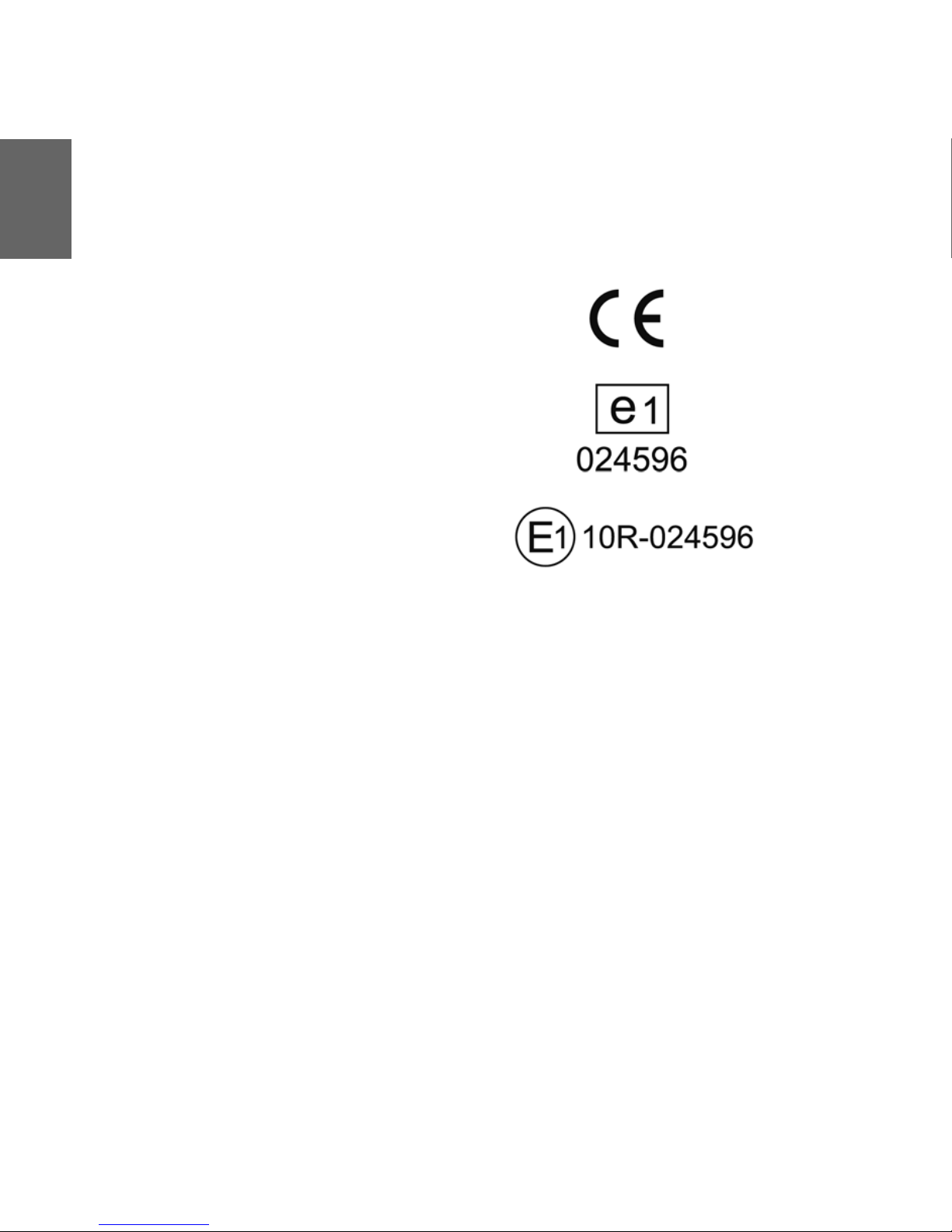
Declaration of conformity
The unit described in this document is in
accordance with the official European
directives. A copy of the declaration of
conformity can be provided.
Type approval
The telematics unit described in this
document has received a type approval from
the German Federal Bureau of Motor Vehicles
and Drivers.
Page 9
EN
Connection overview
9
Connec
tion
overvie
w
Page 10

EN
Connection overview
10
Page 11

EN
What’s in the box
11
What’s
in the
box
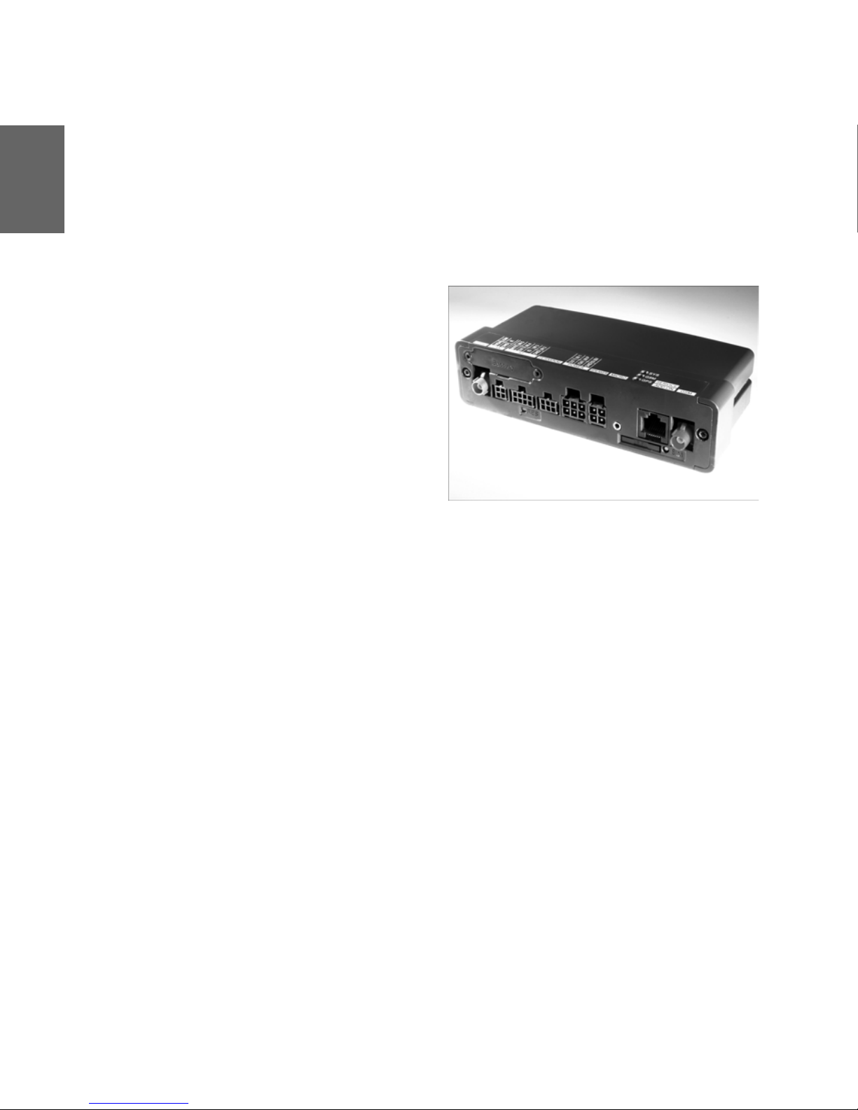
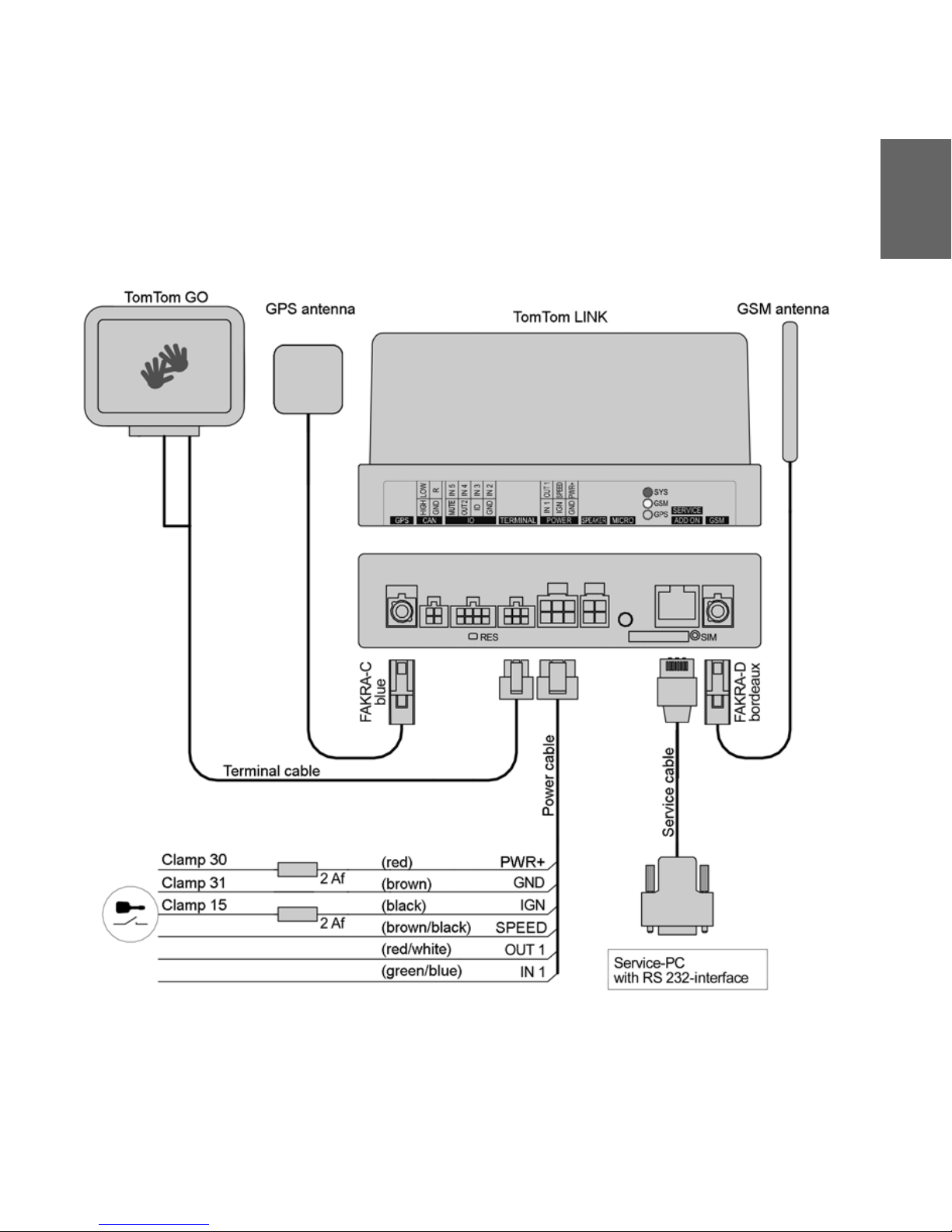
a TomTom LINK black box
A GPS antenna connector (FAKRA blue)
B CAN bus cable connector
C Reset button
D Terminal cable connector
E Power cable connector
F SIM Card holder
G Release button for SIM Card holder
H GSM antenna connector (FAKRA
bordeaux)
I IO cable connector
J 3 LED’s (SYS, GSM, GPS)
K Service/Update cable connector
b Holder
c External GPS antenna with sticky pad and
cleaning cloth
d External GSM antenna with cleaning cloth
e Power cable
f Terminal cable
g Fixatives - 3 self-tapping screws and
washers, 2 sticky pads
h 2 fast-blow 2A motor vehicle fuses with
holders
i Self-adhesive disc (to fix the TomTom GO
windscreen dock on the dashboard)
Page 12

EN
Inserting the SIM Card
12
Inse
rting
the
SIM
Car
d
For the transmission process
To prepare the TomTom LINK for data
exchange with TomTom WEBFLEET you need
to insert the SIM Card in the unit.
1. Press the release button for the SIM Card
holder with a pointed object until it
releases.
2. Now pull out the SIM Card holder.
3. Afterwards gently press the SIM Card into
the SIM Card holder until it engages.
4. Insert the holder with the SIM Card as
shown in the figure.
Page 13

EN
Connecting to power
13
Connec
ting to
power
Important! Connect TomTom LINK to vehicle
voltage (12 V / 24 V / 36 V). Do not connect to
a voltage converter. The three wires GND, IGN
and PWR+ (supply voltage) must be
connected.
1. Connect IGN (ignition) and PWR+ (supply
voltage) to separate 2 A / fast blow fuses.
2. Connect the GND wire (brown) to ground
(clamp 31).
3. Then connect the IGN wire (black) to
ignition (clamp 15).
4. Afterwards connect the PWR+ wire (red) to
carry current (clamp 30).
5. Now connect the SPEED wire (brown/
black) to the odometer pulse (optional).
6. Then insert the 6-pin plug into the multiconnector for the power cable.
Page 14
EN
Connecting GPS antenna
14
Con
nect
ing
GPS
ante
nna
To obtain current position information, the
GPS antenna (supplied with an integrated
magnet and an extra sticky pad) must be
connected to the TomTom LINK.
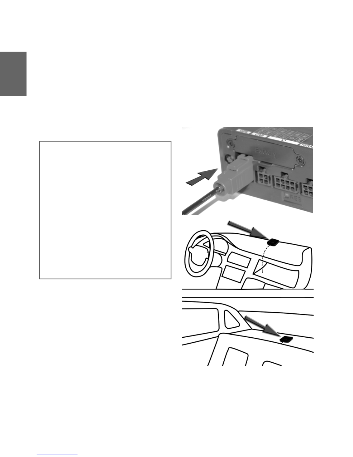
1. Insert the plug of the GPS antenna into the
blue connector for the GPS antenna on the
TomTom LINK.
2. Prepare a smooth, clean, oil free and dry
surface on the dashboard behind the
windscreen.
3. Attach the GPS antenna to a smooth
surface on the dashboard near the
windscreen with the top side pointing to
the sky. Either locate a smooth metal
surface or use the extra sticky pad.
Important note
• Tinted metallised windscreens or those
with integrated filament heating may
obstruct GPS reception. Install the GPS
antenna behind the rear window or on
the outside of the vehicle. The magnet
of the GPS antenna will remain attached
to the outside at speeds up to 180 km/h.
• For installation find a place
unobstructed by metal objects with
clear view of the sky.
• The GPS antenna must be placed with
the sticky pad on an oil free, dry and
clean surface. Keep a minimum
distance of 30 cm between the GSM
antenna and the GPS antenna. Extreme
temperature changes/differences can
affect the adhesive property of the
sticky pad.
Page 15

EN
Connecting GSM antenna
15
Connec
ting
GSM
antenn
a
The GSM antenna with sticky pad must be
connected to TomTom LINK to provide
communication with TomTom WEBFLEET.
1. Insert the plug of the GSM antenna into the
bordeaux connector for the GSM antenna
on the TomTom LINK.
2. Prepare a clean, oil free and dry surface on
the inner side of your windscreen.
3. Remove the protective film from the sticky
side of the GSM antenna.
4. Press the GSM antenna, in the vertical
position, against the inside of your
windscreen until it sticks.
Important note
• The bottom side of the GSM antenna
must have a clear view of the sky.
• Do not interfere with clear vision for the
driver.
• Do not stick the GSM antenna to metal
or any surface other than the
windscreen of your vehicle.
• Place the GSM antenna on the
windscreen with min. 5 cm distance to
the coachwork, so that optimal GSM
transmission is ensured. Keep a
minimum distance of 30 cm between
the GSM antenna and the GPS antenna.
• The GSM antenna must be placed on an
oil free, dry and clean surface. Extreme
temperature changes/differences can
affect the adhesive property of the GSM
antenna.
Note: The sticky, bottom side of the antenna has
to face the outside of the vehicle.
Page 16

EN
Testing operation
16
Test
ing
oper
atio
n
Power/Ignition test
Here you test the connection to power and to
ignition. Before testing make sure you have
carried out the steps described in the previous
chapters.
1. Please check all connections to TomTom
LINK (wires, fuses and antennas).
2. Check that the SIM Card is inserted
correctly.
3. Make sure the ignition is turned off.
4. Disconnect the terminal cable (and IO cable
if used).
5. Disconnect the power supply for a few
seconds.
6. Reconnect the power supply.
7. Now turn on the ignition.
GSM / GPS antenna test
For this test, you may need to move the
vehicle to a location with a clear view of the
sky to facilitate adequate GPS and GSM
reception. For details see the table under
’Diagnostics’.
1. Turn on the ignition.
2. Monitor the yellow GSM LED and green the
GPS LED. Both will start flashing.
3. The yellow GSM LED will switch off if the
device is successfully registered with the
GSM network. The green GPS LED will
switch on if the device has obtained a valid
GPS position.
4. After 10 minutes the yellow GSM LED must
be off and the green GPS LED must be on.
The green GPS LED must not be off. After
about 60 seconds all LED’s must switch off.
At least the green GPS LED must not be off.
Otherwise, check all connections and
repeat the test.
If the yellow GSM LED keeps flashing,
check if the SIM-card is inserted correctly
and if the GSM antenna is connected and
installed in a proper position. If the green
GPS LED keeps flashing, check the GPS
antenna connection and position.
Page 17

EN
Linking to TomTom WEBFLEET
17
Linking
to
TomTo
m
WEBFL
EET
After you have successfully performed the
basic test and the GSM / GPS antenna test you
are ready to start the TomTom WEBFLEET
linking process. After successful linking, the
vehicle will be available in the customer’s
TomTom WEBFLEET account with a valid first
position report.
Before starting the linking process, the
TomTom LINK serial number and the SIM ID
must have been registered. Visit
www.tomtomwork.com/activate and follow
the instructions to register. To start the linking
process:
1. Turn on the ignition and monitor the LED’s.
2. Wait until the yellow GSM LED is off and
the green GPS LED is on.
3. Press the reset button.
4. If the red SYS LED is switched off, the
linking process is completed.
5. If the red SYS LED stops flashing and
remains on, an error occurred during
linking. Make sure the TomTom LINK serial
number and the SIM ID have been
registered with TomTom WEBFLEET and
the basic tests were completed
successfully.
The red SYS LED will be permanently on,
yellow and green will start flashing.
The red SYS LED will start flashing. During
the linking process, the yellow GSM LED
will be switched on to indicate GPRS
connection.
Page 18

EN
Diagnostics
18
Diag
nost
ics
Monitoring operation
Monitor the operation of the TomTom LINK
according to the table below.
Off Flashing (permanently) On
Red
(SYS)
Successfully linked to
TomTom WEBFLEET
In linking mode Not linked to TomTom
WEBFLEET
Yellow
(GSM)
GSM registered, but
no GPRS connection
Not registered, trying to
register
GPRS established, GSM
registered
Green
(GPS)
TomTom LINK is off,
has no connection to
power or is defective
Trying to get a fix (if
flashing rapidly, antenna
failure)
GPS fix
Page 19

EN
Connecting TomTom GO
19
Connec
ting
TomTo
m GO
If you want to use the TomTom GO (510/710/
910) together with TomTom LINK for receiving
orders, text messages and navigation orders,
and for communicating with the office, you
need to connect the TomTom GO to TomTom
LINK.
1. Insert the jack plug of the terminal cable
into the terminal socket.
2. Then insert the other two jack plugs into
the corresponding jacks on the TomTom
GO firmly.
If you have properly connected the two
devices, the connection will be established
automatically. Additional menu items will
appear on your TomTom GO. On the main
navigation view of your TomTom GO the two
red crossed arrows must not be displayed.
Both jack plugs must be inserted properly.
Page 20

EN
Permanent mounting
20
Per
man
ent
mou
ntin
g
Using the holder and tapping screws
To permanently mount the TomTom LINK in a
vehicle use the three self-tapping screws to
mount the holder. Follow the safety
instructions in this document.
1. Choose a flat surface for accurate
positioning stand of the TomTom LINK.
2. Insert the three screws into the
corresponding holes in the holder.
3. Tighten the screws.
4. Insert the TomTom LINK in the holder until
it fully engages.
Important
Make sure you do not damage the TomTom LINK.
Follow the safety instructions in this document.
Page 21
EN
Permanent mounting
21
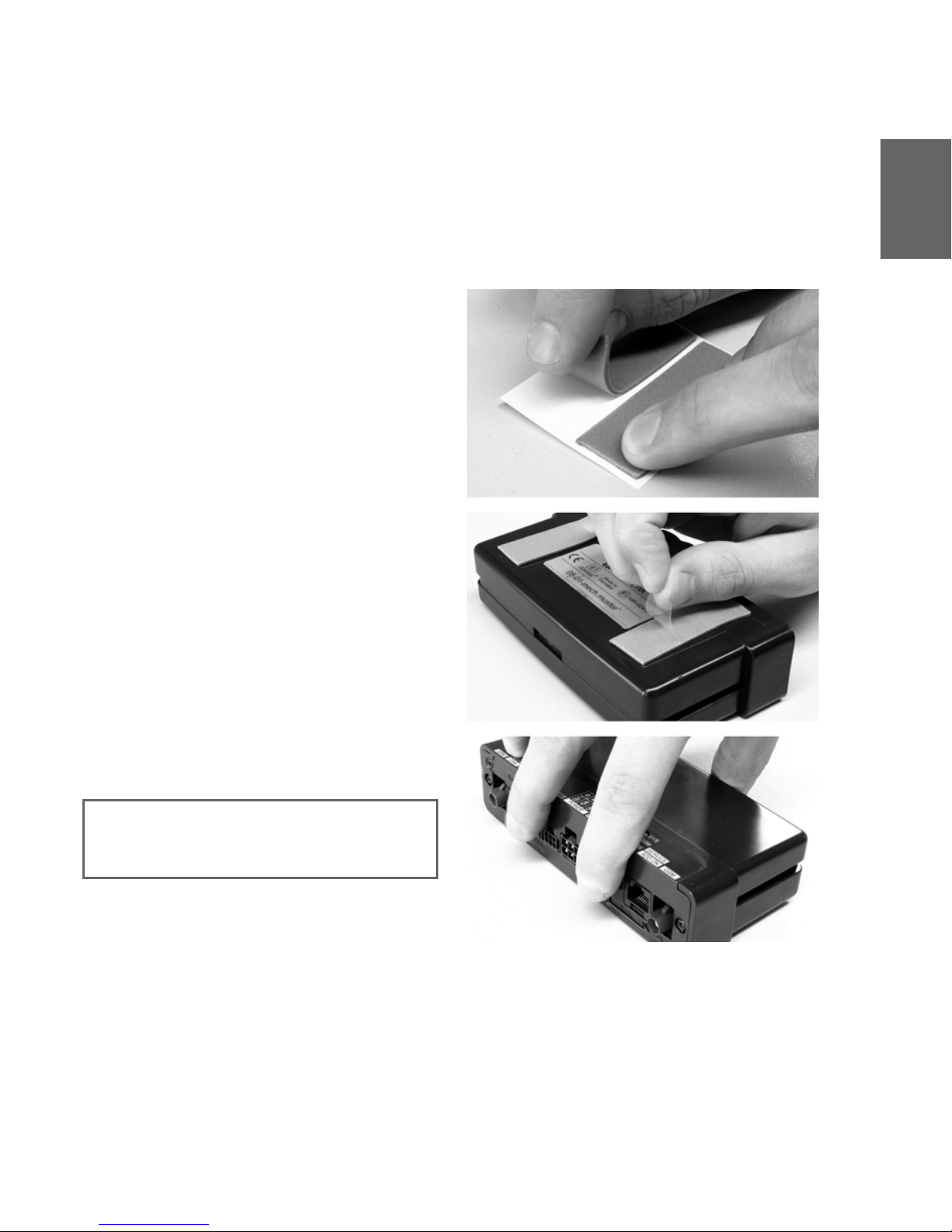
Using sticky pads
You can also affix the TomTom LINK with the
two sticky pads. Follow the safety
instructions in this document.
1. Choose a flat surface for accurate
positioning of the TomTom LINK.
2. Clean the surface with a clean and dry
cloth, so that the surface is oil free, dry and
clean.
3. Remove the protective film from one side
of the pad and stick it to the bottom side of
the TomTom LINK. Repeat the same
procedure with the second sticky pad.
4. Remove the protective films from the other
side of both pads.
5. Place the TomTom LINK with the sticky
pads downwards on the prepared surface.
Press it gently and hold it for a few seconds
until it sticks.
Important
Make sure you do not damage the TomTom LINK.
Follow the safety instructions in this document.
Page 22
EN
Input and output
22
Inpu
t
and
outp
ut
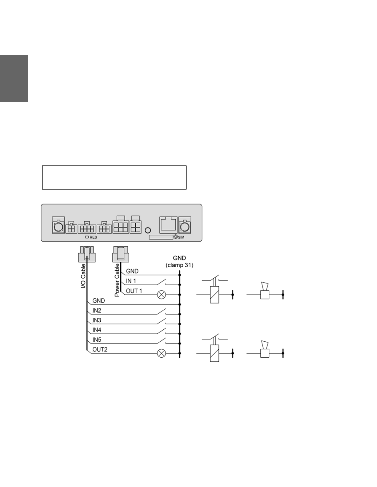
Output OUT 1 is active high (provides power
when active). The connected load must be
connected between GND and OUT 1. Loads
requiring more than 0.5 A must be controlled
with relays. The power provided by the
outputs complies with the supply voltage.
To use inputs they must be connected to
ground. With the inputs of TomTom LINK, up
to five inputs (on/off) can be recorded. It is
possible, for instance, to monitor digital
events like the opening of a loading tail-lift or
the switching of aggregates and to transfer
corresponding status messages.
Caution
Do not switch safety relevant vehicle functions.
Page 23

Einführung
23
DE
Einführ
ung
Herzlichen Glückwunsch!
Sie haben sich für eines der
meistverwendeten und meistbewährten
Telematikgeräte auf dem Markt entschieden.
TomTom LINK bietet Ihnen eine
eindrucksvolle Funktionsvielfalt.
TomTom LINK vereint einen GPS-Empfänger
und ein GSM/GPRS-Modul in einem einzigen
Gerät. Mit TomTom LINK können Sie sich
problemlos über die aktuelle Position Ihres
Fahrzeuges einschließlich der vom Tacho
übermittelten Kilometerleistung informieren.
Alle Daten werden per GPRS übertragen. Die
Daten können bei einer vorübergehenden
Störung des GPRS-Empfangs auch für einen
späteren Versand archiviert werden.
In Kombination mit einem TomTom GO 510/
710/910 können Sie auf einfache Art und
Weise Aufträge, Textnachrichten und
Statusmeldungen verarbeiten.
Sie können auf Ihrem TomTom LINK Aufträge
mit Zielkoordinaten empfangen und auf
Tastendruck zum gewünschten Zielort
navigieren.
Ihre täglichen Geschäftsabläufe werden
dadurch wesentlich vereinfacht.
Page 24

Sicherheit geht vor!
24
DE
Sich
erhei
t
geht
vor!
Wichtige Sicherheitshinweise und
Warnungen
Bitte lesen Sie sich die nachfolgenden
Sicherheitsbestimmungen sorgfältig durch!
TomTom WORK übernimmt keine Haftung für
Schäden, die durch Missachtung der
Sicherheitsbestimmungen entstehen.
Dieses Dokument ist Bestandteil des Produkts.
Verwahren Sie es an einem sicheren Ort, und
übergeben Sie es beim Weiterverkauf an den
neuen Besitzer.
• Wichtig – Eine unsachgemäße Installation
kann Schäden verursachen!
Die Installation und Inbetriebnahme des
Geräts darf ausschließlich durch
autorisiertes Personal erfolgen,
z. B. durch ein qualifiziertes
Rundfunkfachgeschäft oder eine
Fachwerkstatt für Automobilelektrik! Die
Qualitätsrichtlinien des
Automobilgewerbes sind einzuhalten.
• Achtung - Verletzungsgefahr bei Unfällen!
Installieren Sie das Gerät oder dessen
Zubehörteile nicht im Entfaltungsbereich
von Airbags oder im Kopf- oder
Kniebereich! Suchen Sie den
Installationsort so aus, dass das Ablesen
von Anzeigegeräten, die Funktion von
Sicherheitsausrüstungen und die
Betätigung von Bedienelementen nicht
beeinträchtigt wird.
• Achtung – Gefahr von Karosserieschäden!
Achten Sie darauf, dass sie keine
tragenden oder sicherheitsrelevanten Teile
der Karosserie anbohren! Es kann nicht
gewährleistet werden, dass diese nach
einer Modifikation weiterhin korrekt
funktionieren werden.
• Achtung – Brandgefahr!
Achten Sie darauf, keine verdeckten
Kabelbäume, Kraftstoffleitungen oder
ähnliche Komponenten anzubohren!
Dadurch können Brände entstehen.
• Achtung – Gefahr beim Betrieb in
unzulässiger Umgebung!
Das GSM-Modul des TomTom LINK kann
bei elektrischen Geräten – z. B.
Herzschrittmachern, Hörgeräten,
medizinischen Geräten für die
intensivmedizinische Versorgung und
Luftfahrtausrüstungen – Störungen
verursachen. Die in diesen Geräten
verursachten Störungen können die
Gesundheit oder das Leben der Nutzer
gefährden. Verwenden Sie das Gerät nicht
in der Nähe von nicht abgeschirmten
elektrischen Geräten oder in Umgebungen,
in denen der Betrieb von Mobiltelefonen
verboten ist, z. B. in Krankenhäusern und
Flugzeugen! Schalten Sie das Gerät ab,
falls solche Ausrüstungen gestört werden
könnten.
• Achtung – Explosionsgefahr!
In bestimmten Teilen des TomTom LINK
können Funken entstehen, die Explosionen
verursachen können. Dies bedeutet
Page 25

Sicherheit geht vor!
25
DE
Verletzungs- und Lebensgefahr.
Verwenden Sie das Gerät daher nicht in
hoch explosionsgefährdeten Bereichen!
Wenn Sie Ihren TomTom LINK in einem
flüssiggasbetriebenen Fahrzeug
verwenden, beachten Sie die
Sicherheitsvorschriften des Landes, in dem
das Fahrzeug betrieben wird.
• Warnung – Reparatur und Austausch!
Reparaturen dürfen nur von autorisiertem
und qualifiziertem Personal durchgeführt
werden! Tauschen Sie defekte Teile des
Geräts niemals selbst aus. Übergeben Sie
das defekte Gerät an TomTom WORK. Nur
das qualifizierte Personal von TomTom
WORK ist zur Durchführung von
Reparaturen und zum Austausch von
Teilen autorisiert.
• Warnung – Gefahr von Geräteschäden!
Kontakt mit Wasser oder anderen
Flüssigkeiten kann zu Kurzschlüssen im
Inneren des Geräts führen. Durch Kontakt
mit Wasser kann das Gerät beschädigt
werden. Das Gerät darf nur in
wassergeschützter Umgebung betrieben
und gelagert werden.
• Achtung – Unfallgefahr!
Die Bedienung des Geräts während der
Fahrt lenkt ab und kann zu Unfällen führen.
Im Sinne der Verkehrssicherheit dürfen Sie
nur bei stehendem Fahrzeug Informationen
in das Gerät eingeben.
Page 26

Technische Daten
26
DE
Tec
hnis
che
Date
n
Abmessungen Gehäuse: 145 x 75 x 36 mm
Halterung: 162 x 88 x 28 mm
Ge wi ch t G eh äu se : 2 00 g ( oh ne Ba tt eri e)
Halterung: 120 g
Material Gehäuse: Kunststoffspritzguss PC/ABS
Halterung: Santoprene
Schutzklasse IP 20
Versorgungsspannung 12 V / 24 V / 36 V (min. 9 V – max. 48 V)
Stromverbrauch Bei 14 V: < 120 mA (typisch)
Bei 28 V: < 60 mA (typisch)
Bereitschaft: < 1 mA (typisch)
Schutzsicherungen Betriebsspannung 9 – 48 V mit 2 A/flink
Zündung mit 2 A/flink
Temperatur Betrieb: -20 °C bis +55 °C
Lagerung: -40 °C bis +70 °C
GSM Integriertes Modul, Dual-Band GSM 900, GSM 1800
GSM-Antennenanschluss FAKRA 2 code D (Stecker – bordeaux) – (Antenne –
Buchse)
GPS-Antennenanschluss FAKRA 2 code C (Stecker – blau) – (Antenne – Buchse)
Betriebsspannungsbereich 3 V bis 5 V
Mindestantennengewinn bei 3 V: 15 dB
Maximaler Antennengewinn: 40 dB
Maximaler Rauschwert: 1,5 dB
Zündungseingang Zum Anschluss an die Zündungsklemme, um das Gerät
mit der Zündung ein- und auszuschalten
Digitaleingänge 5 Eingänge auf Masse schaltbar
1 Eingang für Tachometer-Impulse
Dig it ala us gä ng e 2 Au sg än ge, La st auf Ma sse (0 V) , ma x. 0, 5 A
Weitere Schnittstellen Can-Bus, ID-Bus
Page 27

Richtlinien
27
DE
Richtlin
ien
Konformitätserklärung
Das in diesem Dokument beschriebene Gerät
entspricht den geltenden europäischen
Richtlinien. Eine Kopie der
Konformitätserklärung kann zur Verfügung
gestellt werden.
Bauartzulassung
Das in diesem Dokument beschriebene
Telematikgerät besitzt eine vom Deutschen
Kraftfahrtbundesamt vergebene
Bauartzulassung.
Page 28

Anschlussübersicht
28
DE
Ansc
hluss
über
sicht
Page 29

Anschlussübersicht
29
DE
Page 30

Lieferumfang
30
DE
Lief
eru
mfa
ng
a TomTom LINK Black Box
A GPS-Antennenanschluss (FAKRA blau)
B CAN-Bus-Anschluss
C Rückstellknopf (RESET)
D Anschluss für Terminal-Kabel
E Spannungsversorgungsanschluss
F SIM-Kartenhalter
G Auswurfknopf für SIM-Kartenhalter
H GSM-Antennenanschluss (FAKRA
dunkelrot)
I IO-Anschluss
J 3 LEDs (SYS, GSM, GPS)
K Service/Update-Anschluss
b Halterung
c Externe GPS-Antenne, selbstklebend, mit
Reinigungstuch
d Externe GSM-Antenne mit Reinigungstuch
e Stromkabel
f Terminal-Kabel
g Befestigungsmaterial – 3
Gewindeschneidschrauben mit
Unterlegscheiben, 2 Klebestreifen
h 2 Kfz-Sicherungen 2A/flink mit
Sicherungshalterungen
i Selbstklebende Scheibe (zur Anbringung
der TomTom GO Frontscheibenhalterung
auf dem Armaturenbrett)
Page 31

SIM-Karte einsetzen
31
DE
SIMKarte
einsetz
en
SIM-Karte für die Übertragung einsetzen
Um den TomTom LINK für den
Datenaustausch mit TomTom WEBFLEET
vorzubereiten, müssen Sie die SIM-Karte in
das Gerät einsetzen.
1. Drücken Sie mit einem spitzen Gegenstand
auf den Auswurfknopf des SIMKartenhalters, bis die Arretierung des
Kartenhalters gelöst wird.
2. Ziehen Sie den SIM-Kartenhalter heraus.
3. Drücken Sie die SIM-Karte sorgfältig in den
SIM-Kartenhalter hinein, bis sie einrastet.
4. Schieben Sie den Kartenhalter zusammen
mit der SIM-Karte wie abgebildet in das
Gerät hinein.
Page 32

Anschluss an die Stromversorgung
32
DE
Ans
chlu
ss
an
die
Stro
mve
rsor
gun
g
Wichtig! Schließen Sie den TomTom LINK an
die Bordstromversorgung (12 V/24 V/36 V) an.
Verwenden Sie keinen Spannungswandler.
Die drei Leitungen GND (Masse), IGN
(Zündung) und PWR+
(Versorgungsspannung) müssen alle
angeschlossen werden.
1. Schließen Sie das IGN-Kabel (Zündung)
und das PWR+ Kabel (Versorgungsspannung) über getrennte, 2 A/flink
Sicherungen an.
2. Verbinden Sie das Massekabel (braun) mit
der Masse (Klemme 31).
3. Verbinden Sie anschließend das IGN-Kabel
(schwarz) mit der Zündung (Klemme 15).
4. Verbinden Sie danach das PWR+ Kabel
(rot) mit dem stromführenden Anschluss
(Klemme 30).
5. Schließen Sie nun das SPEED-Kabel an den
Tacho-Impulsgeber an (optional).
6. Schließen Sie danach den 6-poligen
Stecker an den mehrpoligen
Stromanschluss an.
Page 33

GPS-Antenne anschließen
33
DE
GPSAntenne
anschlie
ßen
Schließen Sie für die Positionserfassung die
GPS-Antenne (ausgestattet mit Klebestreifen
und integriertem Magnet) an den TomTom
Link an.
1. Stecken Sie den Stecker der GPS-Antenne
an den blauen GPS-Antennenanschluss
des TomTom LINK an.
2. Bereiten Sie eine ebene, saubere, fettfreie
und trockene Befestigungsfläche auf dem
Armaturenbrett hinter der
Windschutzscheibe vor.
3. Befestigen Sie die GPS-Antenne mit der
Oberseite zum Himmel gerichtet auf einer
glatten Oberfläche am Armaturenbrett in
der Nähe der Windschutzscheibe.
Benutzen Sie dazu entweder eine glatte
Metalloberfläche oder den zusätzlichen
Klebestreifen.
Wichtiger Hinweis
•Durch Metallschichtbedampfung
getönte oder mit Heizfäden versehene
Windschutzscheiben können den GPSEmpfang behindern. Befestigen Sie die
GPS-Antenne hinter der Heckscheibe
oder außen am Fahrzeug. Der Magnet
der GPS-Antenne gibt sicheren Halt bis
zu einer Geschwindigkeit von 180 km/h.
• Installieren Sie die Antenne so, dass sie
nicht durch metallische Gegenstände
abgeschirmt wird und eine freie Sicht
zum Himmel gewährleistet wird.
•Die GPS-Antenne muss mit der
Haftseite auf einer fettfreien, trockenen
und sauberen Oberfläche befestigt
werden. Achten Sie auf einen
Mindestabstand von 30 cm zwischen
der GSM- und der GPS-Antenne.
Extreme Temperaturwechsel und unterschiede können die
Hafteigenschaften des Klebestreifens
beeinträchtigen.
Page 34

GSM-Antenne anschließen
34
DE
GS
MAnt
enn
e
ansc
hlie
ßen
Die selbstklebende GSM-Antenne muss an
den TomTom LINK angeschlossen werden,
um die Verbindung zu TomTom WEBFLEET zu
ermöglichen.
1. Schließen Sie den Kabelstecker der GSMAntenne an den bordeaux-farbenen GSMAntennenanschluss des TomTom LINK an.
2. Bereiten Sie eine saubere, fettfreie und
trockene Befestigungsfläche auf der
Innenseite der Windschutzscheibe vor.
3. Entfernen Sie die Schutzfolie von der
Haftfläche der GSM-Antenne.
4. Drücken Sie die senkrecht ausgerichtete
GSM-Antenne gegen die Innenseite der
Windschutzscheibe, bis die Antenne an der
Scheibe haftet.
Wichtiger Hinweis
• Die Unterseite der GSM-Antenne muss
über freie Sicht zum Himmel verfügen.
• Das Sichtfeld des Fahrers darf nicht
beeinträchtigt werden.
• Befestigen Sie die GSM-Antenne
ausschließlich an der
Windschutzscheibe Ihres Fahrzeugs;
insbesondere sollte die Antenne nicht
auf einer Metalloberfläche befestigt
werden.
• Um einen optimalen GSM-Empfang zu
gewährleisten, befestigen Sie die GSMAntenne mit einem Mindestabstand von
5 cm zum Karosserierahmen auf der
Windschutzscheibe. Achten Sie auf
einen Mindestabstand von 30 cm
zwischen der GSM- und der GPSAntenne.
• Die GSM-Antenne muss auf einer
fettfreien, trockenen und sauberen
Oberfläche befestigt werden. Extreme
Temperaturwechsel und -unterschiede
können die Hafteigenschaften der GSMAntenne beeinträchtigen.
Hinweis: Die selbstklebende Unterseite der GSMAntenne muss nach außen gerichtet sein.
Page 35

Funktionsprüfung
35
DE
Funktio
nsprüfu
ng
Stromversorgungs-/Zündungtest
Hier prüfen Sie die Verbindung zur
Stromversorgung und zur Zündung. Bevor Sie
den Test starten stellen Sie sicher, dass Sie die
in den vorigen Kapiteln beschriebenen
Schritte ordnungsgemäß ausgeführt haben.
1. Bitte überprüfen Sie alle Verbindungen
zum TomTom LINK (Kabel, Sicherungen
und Antennen).
2. Überprüfen Sie, dass die SIM-Karte korrekt
eingelegt ist.
3. Überprüfen Sie, dass die Zündung
ausgeschaltet ist.
4. Ziehen Sie das Terminal-Kabel (und das IOKabel, falls verwendet) ab.
5. Trennen Sie die Stromversorgung für
einige Sekunden.
6. Schließen Sie die Stromversorgung wieder
an.
7. Schalten Sie nun die Zündung ein.
Überprüfen der GSM-/GPS-Antenne
Für diese Überprüfung müssen Sie das
Fahrzeug an einen Ort fahren, der freie Sicht
zum Himmel bietet, um einen einwandfreien
GPS- und GSM-Empfang zu gewährleisten.
Details entnehmen Sie der Tabelle unter
’Funktionsanalyse’.
1. Schalten Sie die Zündung ein.
2. Beobachten Sie die gelbe GSM-LED und
die grüne GPS-LED. Beide werden
zunächst blinken.
3. Die gelbe GSM-LED erlischt, wenn sich das
Gerät erfolgreich im GSM-Netz angemeldet
hat. Die grüne GPS-LED beginnt dauerhaft
zu leuchten, wenn das Gerät eine gültige
GPS-Position empfangen hat.
4. Nach 10 Minuten muss die gelbe GSM LED
aus und die grüne GPS LED an sein.
Die grüne GPS-LED darf nicht aus sein. Nach ca.
60 Sekunden müssen alle LEDs erlöschen.
Zumindest die grüne GPS-LED darf nicht aus
sein. Andernfalls überprüfen Sie bitte alle
Verbindungen und wiederholen Sie den Vorgang.
Wenn die gelbe GSM-LED weiterhin blinkt,
überprüfen Sie, ob die SIM-Karte korrekt
eingesetzt und die GSM-Antenne
ordnungsgemäß installiert und angeschlossen
ist. Wenn die grüne GPS-LED weiterhin blinkt,
überprüfen Sie, ob die GPS-Antenne korrekt
angeschlossen und positioniert ist.
Page 36

Verbinden mit TomTom WEBFLEET
36
DE
Ver
bind
en
mit
Tom
Tom
WE
BFL
EET
Nach der erfolgreichen Durchführung der
Grundprüfung und der GSM-/GPSAntennenüberprüfung können Sie eine
Verbindung zu TomTom WEBFLEET
herstellen. Nach dem Herstellen der
Verbindung erscheint das Fahrzeug mit einem
ersten gültigen Positionsbericht im TomTomWEBFLEET-Konto des Kunden.
Die Verbindung kann nur hergestellt werden,
wenn die TomTom-LINK-Seriennummer und
die SIM-ID zuvor registriert wurden. Zur
Registrierung besuchen Sie bitte die Seite
www.tomtomwork.com/activate und folgen
den dort zu sehenden Anweisungen. Um die
Verbindung herzustellen, gehen Sie wie folgt
vor:
1. Schalten Sie die Zündung ein und
beobachten Sie die LEDs.
2. Warten Sie, bis die gelbe GSM-LED erlischt
und die grüne GPS-LED dauerhaft leuchtet.
3. Drücken Sie den Rückstellknopf (RESET).
4. Wenn die rote SYS-LED erlischt, ist die
Verbindung hergestellt.
5. Wenn die rote SYS-LED statt zu blinken
permanent leuchtet, ist beim
Verbindungsaufbau ein Fehler aufgetreten.
Überprüfen Sie, ob die TomTom-LINKSeriennummer und die SIM-ID bei
TomTom WEBFLEET registriert wurden
und die Grundprüfung erfolgreich
durchgeführt wurde.
Die rote SYS-LED leuchtet kontinuierlich; die
gelbe und die grüne LED beginnen zu blinken.
Während des Verbindungsprozesses wird die
GPRS-Verbindung durch das Aufleuchten der
gelben GSM-LED signalisiert.
Page 37

Funktionsanalyse
37
DE
Funktio
nsanaly
se
Betriebsüberwachung
Der Betrieb des TomTom LINK kann anhand
der nachfolgenden Tabelle überwacht
werden.
Aus Blinkt (dauerhaft) Leuchtet
Rot
(SYS)
Verbindung zu
TomTom WEBFLEET
hergestellt
Verbindungsversuch im
Gange
Nicht mit TomTom
WEBFLEET verbunden
Gelb
(GSM)
Im GSM-Netz
angemeldet, jedoch
ohne GPRSVerbindung
Nicht angemeldet,
Anmeldeversuch im
Gange
GPRS-Verbindung
hergestellt, im GSM-Netz
angemeldet
Grün
(GPS)
TomTom LINK ohne
Stromversorgung,
ausgeschaltet oder
defekt
Ortungsversuch im
Gange (bei schnellem
Blinken: Antenne defekt)
Gültige GPS-Position
Page 38

Verbindung mit TomTom GO herstellen
38
DE
Ver
bind
ung
mit
Tom
Tom
GO
hers
telle
n
Sie können einen TomTom GO (510/710/910)
mit Ihrem TomTom LINK verbinden, um
Aufträge, Textnachrichten und
Navigationsanweisungen zu empfangen und
mit Ihrer Zentrale zu kommunizieren.
1. Schließen Sie den Stecker des TerminalKabels an den Anschluss für das TerminalKabel an.
2. Schließen Sie danach die anderen beiden
Kabelstecker an die entsprechenden
Anschlüsse des TomTom GO fest an.
Wenn Sie das Kabel korrekt mit beiden
Geräten verbunden haben, wird die
Verbindung automatisch hergestellt. Auf
Ihrem TomTom GO werden nun zusätzliche
Menüpunkte erscheinen. Auf der
Navigationshauptansicht Ihres TomTom GO
darf der rot durchgestrichene Doppelpfeil
nicht angezeigt werden.
Beide Stecker müssen fest angeschlossen sein.
Page 39

Festeinbau
39
DE
Festein
bau
Mit Halterung und
Gewindeschneidschrauben
Zum Festeinbau des TomTom LINK können
Sie die Halterung mit den drei
Gewindeschneidschrauben im Fahrzeug
befestigen. Bitte beachten Sie die
Sicherheitshinweise in diesem Dokument.
1. Wählen Sie eine ebene Oberfläche, auf der
Ihr TomTom LINK korrekt aufgestellt
werden kann.
2. Führen Sie die drei Schrauben in die
Bohrungen der Halterung ein.
3. Ziehen Sie die Schrauben fest.
4. Legen Sie Ihren TomTom LINK so in die
Halterung ein, dass er einrastet.
Wichtig
Achten Sie darauf, Ihren TomTom LINK nicht zu
beschädigen. Bitte beachten Sie die
Sicherheitshinweise in diesem Dokument.
Page 40

Festeinbau
40
DE
Mit Klebestreifen
Sie können Ihren TomTom LINK auch mit den
zwei Klebestreifen befestigen. Bitte beachten
Sie die Sicherheitshinweise in diesem
Dokument.
1. Wählen Sie eine ebene Oberfläche, auf der
Ihr TomTom LINK korrekt aufgestellt
werden kann.
2. Reinigen Sie die Oberfläche mit einem
sauberen, trockenen Tuch und stellen Sie
sicher, dass die Oberfläche fettfrei, trocken
und sauber ist.
3. Entfernen Sie die Schutzfolie auf einer
Seite des Klebestreifens, und kleben Sie
ihn auf die Unterseite des TomTom LINK
auf. Kleben Sie auf die gleiche Art und
Weise den zweiten Klebestreifen auf.
4. Entfernen Sie die Schutzfolie von der
anderen Seite der beiden Klebestreifen.
5. Legen Sie den TomTom LINK mit den
Klebestreifen nach unten auf die
vorbereitete Oberfläche. Drücken Sie das
Gerät vorsichtig für einige Sekunden an,
bis es an der Oberfläche haften bleibt.
Wichtig
Achten Sie darauf, Ihren TomTom LINK nicht zu
beschädigen. Bitte beachten Sie die
Sicherheitsbestimmungen in diesem Dokument.
Page 41

Eingänge und Ausgänge
41
DE
Eingän
ge und
Ausgän
ge
Der Ausgang OUT 1 ist vom Typ „active high“
(im aktiven Zustand stromführend). Der
angeschlossene Verbraucher muss zwischen
der Masse (GND) und dem Ausgang 1 (OUT 1)
angeschlossen werden. Bei einem
Strombedarf über 0,5 A müssen Verbraucher
über Relais geschaltet werden. Die an den
Ausgängen anliegende Spannung entspricht
der Versorgungsspannung.
Um Eingänge zu nutzen, müssen sie auf Masse
gelegt werden. Die Eingänge von TomTom
LINK können bis zu fünf Eingangssignale (Ein/
Aus) erfassen. So lassen sich digitale
Ereignisse, wie z. B. die Öffnung einer
Laderaumtür bzw. der Kofferraumklappe oder
das Schalten von Aggregaten überwachen
und entsprechende Statusmeldungen
verschicken.
Achtung
Sicherheitsrelevante Fahrzeugfunktionen dürfen
nicht mit diesem Ausgang geschaltet werden.
Page 42

Page 43

Introduction
43
FR
Introdu
ction
Félicitations
Vous avez choisi l'un des appareils de
télématique les plus réputés et fiables du
marché. Le TomTom LINK vous offre un large
éventail de fonctionnalités.
Il intègre dans une seule et même unité un
récepteur GPS et un module GSM/GPRS. Avec
le TomTom LINK, vous obtenez facilement la
position courante du véhicule, y compris le
kilométrage tel qu'indiqué sur le compteur
kilométrique.
Toutes les données sont transmises via le
GPRS. Celles-ci peuvent également être
stockées pour être transmises après une perte
temporaire de la réception GPRS.
Associé au TomTom GO 510/710/910, le
TomTom LINK vous permet de gérer
facilement les commandes, les messages
texte et les messages d'état.
Vous pouvez recevoir vos commandes avec
l'adresse de destination sur votre TomTom
LINK et les instructions de navigation vers
cette destination vous sont communiquées
par simple appui d’un bouton.
Votre activité quotidienne s'en trouvera
largement simplifiée.
Page 44

La sécurité d'abord
44
FR
La
séc
urité
d'ab
ord
Conseils de sécurité et avertissements
importants
Lisez attentivement les instructions de
sécurité ci-dessous!
TomTom WORK ne peut être tenu
responsable des dommages résultant du nonrespect des instructions de sécurité.
Ce document fait partie du produit. Conservezle en lieu sûr et remettez-le à tout nouveau
propriétaire du produit.
• Important: une mauvaise installation peut
provoquer des dommages!
L'installation et la première utilisation de
l'unité peuvent uniquement être effectuées
par un personnel agréé, c'est-à-dire un
revendeur radio qualifié
ou un atelier d'électronique automobile!
Prenez en compte des normes de qualité
de l'industrie automobile.
• Attention: risque de blessures en cas
d'accident!
N'installez pas l'unité ou ses accessoires
dans la zone de gonflage des airbags ou
dans la zone d'impact de la tête et des
genoux! Cherchez soigneusement un
emplacement qui évitera toute interférence
avec les instruments, l'équipement de
sécurité et les commandes.
• Attention: risque d'endommager le
châssis!
Assurez-vous de ne pas percer dans des
endroits du châssis ayant des fonctions
structurelles ou liées à la sécurité! Vous ne
pouvez jamais être sûr qu'ils
fonctionneront normalement après
modification.
• Attention: risque d'incendie!
Assurez-vous de ne pas percer dans les
faisceaux de fils couverts, les conduits
d'essence ou d'autres composants
similaires! Ceci risquerait de provoquer un
incendie.
• Attention: danger en cas d'utilisation dans
les zones interdites!
Le module GSM du TomTom LINK peut
provoquer des interférences avec les
dispositifs électroniques comme les
pacemakers cardiaques, les appareils
auditifs, les appareils électroniques utilisés
en soins intensifs ou le matériel
aéronautique. L'interférence avec ces
appareils risque de mettre en danger la
santé ou la vie de leurs utilisateurs. Veuillez
éviter d'utiliser votre TomTom LINK à
proximité des unités électriques non
protégées ou dans les zones où les
téléphones portables sont interdits comme
les hôpitaux et les avions! Éteignez
l'appareil s'il y a un risque d'interférence
avec ces équipements.
• Attention: risque d'explosion!
Certaines pièces du TomTom LINK peuvent
provoquer des étincelles susceptibles
d'entraîner des explosions. Ceci risque de
mettre en danger la santé et la vie des
personnes. Veuillez ne pas utiliser le
TomTom LINK dans les zones où il y a un
Page 45

La sécurité d'abord
45
FR
grand risque d'explosion! Si vous utilisez le
TomTom LINK dans un véhicule alimenté
au gaz liquéfié (GPL), veuillez suivre les
règlements de sécurité du pays où le
véhicule est utilisé.
• Attention: réparation et remplacement!
Les réparations peuvent uniquement être
effectuées par du personnel agréé et
qualifié! N'essayez jamais de remplacer
vous-même des pièces endommagées de
l'appareil. Remettez l'appareil défectueux à
TomTom WORK. Seul le personnel qualifié
de TomTom WORK est autorisé à changer
ou à remplacer des pièces.
• Attention: appareil endommagé!
Le contact avec l'eau ou d'autres liquides
peut provoquer un court-circuit dans
l'appareil. En règle générale, tout contact
avec l'eau peut endommager l'appareil.
Veuillez utiliser et conserver votre appareil
dans un lieu à l'abri de l'humidité.
• Attention: risque d'accidents!
L'utilisation de l'appareil en conduisant
peut distraire le conducteur et provoquer
ainsi des accidents. Pour assurer votre
sécurité routière, n'entrez les informations
dans l'appareil que lorsque vous ne
conduisez pas.
Page 46

Données techniques
46
FR
Don
née
s
tech
niqu
es
Dimensions Appareil : 145 x 75 x 36 mm
Support : 162 x 88 x 28 mm
Poids Appareil : 200 g (sans batterie)
Support : 120 g
Matières Appareil : Corps en plastique PC/ABS moulé par injection
Support : santoprène
Classe de protection IP 20
Tension d'alimentation 12 V / 24 V / 36 V (min.9 V - max. 48 V)
Consommation d'énergie À 14 V : normalement < 120 mA
À 28 V : normalement < 60 mA
En veille : normalement < 1 mA
Protection par fusible Tension de fonctionnement 9 - 48 V avec fusible rapide 2 A
Contact avec fusible rapide 2 A
Température -20 à +55 °C (fonctionnement)
-40 à +70°C (stockage)
GSM Module intégré, bi-bande GSM 900, GSM 1800
Connecteur d'antenne GSM FAKRA 2 code D (mâle - bordeaux) - (antenne femelle)
Connecteur d'antenne GPS FAKRA 2 code C (mâle - bleu) - (antenne femelle)
Tension d'alimentation 3 V à 5 V
Gain minimum de l'antenne à 3 V : 15 dB
Gain maximum de l'antenne : 40 dB
Bruit maximum : 1,5 dB
Entrée contact À brancher sur la borne de contact pour allumer/éteindre
l'appareil simultanément avec le contact
Entrées numériques 5 entrées commutables à la terre
1 entrée pour les impulsions du tachymètre
Sorties numériques 2 sorties, charge à la terre (0 V), max. 0,5 A
Autres interfaces Bus CAN, bus ID
Page 47

Directives
47
FR
Directiv
es
Déclaration de conformité
Le produit décrit dans ce document est
conforme aux directives européennes
officielles. Une copie de la déclaration de
conformité peut vous être délivrée.
Homologation de type
Le produit de télématique décrit dans ce
document a reçu une homologation de type
de l'Office Fédéral allemand pour la circulation
routière.
Page 48

Schéma de connexion
48
FR
Sché
ma
de
conn
exio
n
Page 49

Schéma de connexion
49
FR
Page 50

Contenu du coffret
50
FR
Con
tenu
du
coffr
et
a Boîte noire TomTom LINK
A Connecteur d'antenne GPS (FAKRA
bleu)
B Connecteur du câble bus CAN
C Bouton de réinitialisation
D Connecteur du câble du terminal
E Connecteur du câble d'alimentation
F Support carte SIM
G Bouton d'ouverture du support carte
SIM
H Connecteur d'antenne GSM (FAKRA
bordeaux)
I Connecteur du câble entrée/sortie
J 3 témoins lumineux (SYS, GSM, GPS)
K Connecteur de câble de Maintenance/
Mise à jour
b Support
c Antenne GPS externe avec adhésif de
fixation et chiffon de nettoyage
d Antenne GSM externe avec chiffon de
nettoyage
e Câble d'alimentation
f Câble du terminal
g Éléments de fixation: 3 vis autotaraudeuses
et rondelles, 2 adhésifs de fixation
h 2 fusibles à fusion rapide, 2 A (ampères),
avec porte-fusibles
i Disque auto-adhésif (pour attacher le Socle
pour pare-brise du TomTom GO au tableau
de bord)
Page 51

Insertion de la carte SIM
51
FR
Insertio
n de la
carte
SIM
Pour le processus de transmission
Afin de préparer le TomTom LINK à l'échange
de données avec TomTom WEBFLEET, vous
devez insérer la carte SIM dans l'appareil.
1. Appuyez sur le bouton d'ouverture du
support de carte SIM avec un objet pointu.
2. Retirez-le de l'unité.
3. Ensuite, insérez délicatement la carte SIM
dans son support jusqu'à ce qu'elle
s'enclenche.
4. Insérez le support avec la carte SIM comme
indiqué sur le schéma.
Page 52

Raccordement à l'alimentation
52
FR
Rac
cord
eme
nt à
l'ali
men
tatio
n
Important! Raccordez votre TomTom LINK à
une tension automobile (12 V / 24 V / 36 V). Ne
le branchez pas sur un transformateur. Les
trois fils - terre, contact et phase PWR+
doivent être branchés.
1. Raccordez les fils de contact et de phase
PWR+ à deux fusibles rapides séparés 2 A.
2. Raccordez le fil de terre (marron) à la terre
(borne 31).
3. Puis raccordez le fil contact (noir) au
contact (borne 15).
4. Raccordez maintenant le fil PWR+ (rouge)
pour véhiculer le courant (borne 30).
5. Raccordez le fil SPEED (marron/noir) au
compteur kilométrique (facultatif).
6. Puis, insérez la prise à 6 broches dans le
multiconnecteur du câble d'alimentation.
Page 53

Connexion de l'antenne GPS
53
FR
Connex
ion de
l'anten
ne GPS
Pour obtenir des informations sur votre
position courante, l'antenne GPS (livrée avec
un aimant intégré et un adhésif de fixation
supplémentaire) doit être connectée au
TomTom LINK.
1. Insérez la prise de l'antenne GPS dans le
connecteur bleu pour antenne GPS du
TomTom LINK.
2. Choisissez une surface propre, lisse, sèche
et non grasse sur le tableau de bord
derrière le pare-brise.
3. Fixez l'antenne GPS sur une surface lisse du
tableau de bord près de votre pare-brise, la
partie du haut dirigée vers le ciel.
Choisissez une surface métallique lisse ou
utilisez l'adhésif de fixation supplémentaire.
Important!
• Les pare-brises athermiques teintés ou
les pare-brises chauffants peuvent
entraver la réception GPS. Installez
l'antenne GPS derrière la vitre arrière ou
à l'extérieur du véhicule. L'aimant de
l'antenne GPS placé à l'extérieur résiste
jusqu'à une vitesse de 180 km/h.
• Pour installer l'antenne, choisissez un
endroit non obstrué par des objets
métalliques offrant une vue dégagée sur
le ciel.
• L'antenne GPS doit être fixée avec
l'adhésif de fixation sur une surface
sèche, propre et non grasse. Gardez au
moins une distance de 30 cm entre
l’antenne GPS et l’antenne GSM. Les
écarts/changements de température
extrêmes peuvent affecter la capacité
d'adhésion de la fixation.
Page 54

Connexion de l'antenne GSM
54
FR
Con
nexi
on
de
l'ant
enn
e
GS
M
L'antenne GSM avec son support adhésif doit
être connectée au TomTom LINK pour assurer
la communication avec TomTom WEBFLEET.
1. Insérez la prise de l'antenne dans le
connecteur bordeaux pour l'antenne GSM
du TomTom LINK.
2. Préparez une surface propre, sèche et non
grasse sur la face intérieure de votre parebrise.
3. Ôtez le film protecteur du côté adhésif de
l'antenne GSM.
4. Appuyez l'antenne GSM en position
verticale contre l'intérieur de votre parebrise jusqu'à ce qu'elle adhère à celui-ci.
Important!
• Le dos de l'antenne GSM doit être dirigé
vers le ciel et la vue entre les deux doit
être dégagée.
• Veillez à ne pas obstruer la vision du
conducteur.
• Évitez de fixer l'antenne sur du métal ou
sur une surface autre que le pare-brise
de votre véhicule.
• Placez l'antenne GSM sur le pare-brise à
5 cm au moins de la carrosserie de
façon à assurer une transmission
optimale. Gardez au moins une distance
de 30 cm entre l’antenne GPS et
l’antenne GSM.
• L'antenne GSM doit être placée sur une
surface propre, sèche et non grasse.
Les écarts/changements de
température extrêmes peuvent affecter
ses propriétés adhésives.
Remarque: La partie adhésive au dos de
l'antenne doit être dirigée vers l'extérieur du
véhicule.
Page 55

Tests
55
FR
Tests
Test d’alimentation/d’allumage
Ici vous testez la connexion avec
l’alimentation et avec l’allumage. Avant de
tester, vérifiez que vous avez effectué les
actions décrites dans les chapitres
précédents.
1. Veuillez vérifier toutes les connexions au
TomTom LINK (câbles, fusibles et
antennes).
2. Assurez-vous que la carte SIM est
correctement insérée.
3. Assurez-vous que le contact est coupé.
4. Débranchez le câble du terminal (et le câble
entrée/sortie le cas échéant).
5. Débranchez l'alimentation pendant
quelques secondes.
6. Rebranchez l'alimentation.
7. Maintenant, mettez le contact.
Test des antennes GSM / GPS
Pour ce test, placez votre voiture dans un
endroit offrant une vue dégagée sur le ciel
pour une meilleure réception GPS et GSM.
Pour obtenir des détails supplémentaires
référez-vous au tableau dans ’Diagnostic’.
1. Mettez le contact.
2. Surveillez le témoin lumineux GSM jaune et
le témoin lumineux GPS vert. Tous deux
commencent à clignoter.
3. Le témoin lumineux GSM jaune s'éteindra
si l'appareil est enregistré sur le réseau
GSM. Le témoin lumineux GPS vert
s'allumera si l'appareil a obtenu une
position GPS valide.
4. Après 10 minutes le témoin GSM jaune doit
être éteint et le témoin GPS vert doit être
allumé.
Le témoin lumineux GPS vert ne doit pas être
éteint. Après 60 secondes environ, tous les
témoins lumineux doivent s'éteindre.
Au moins le témoin lumineux GPS vert ne doit
pas être éteint. Sinon, vérifiez toutes les
connexions et recommencez le test.
Si le témoin GSM jaune clignote encore, vérifiez
que la carte SIM est correctement insérée et que
l'antenne GSM est connectée et installée dans la
bonne position. Si le témoin GPS vert clignote
encore, vérifiez la connexion et la position de
l'antenne GPS.
Page 56

Liaison avec TomTom WEBFLEET
56
FR
Liais
on
ave
c
Tom
Tom
WE
BFL
EET
Après avoir effectué le test de base et le test
des antennes GSM / GPS, vous pouvez
entamer la procédure de liaison avec TomTom
WEBFLEET. Une fois la liaison établie, le
véhicule sera disponible dans le compte
TomTom WEBFLEET du client avec un
premier rapport valide sur sa position.
Avant de commencer la procédure de liaison,
le numéro de série TomTom LINK et l'identité
de la carte SIM doivent être enregistrés. Pour
les enregistrer, rendez-vous sur
www.tomtomwork.com/activate et suivez les
instructions. Pour entamer la procédure de
liaison:
1. Mettez le contact et surveillez les témoins
lumineux.
2. Attendez jusqu'à ce que le témoin lumineux
GSM jaune soit éteint et que le témoin GPS
vert s'allume.
3. Appuyez sur le bouton de réinitialisation.
4. Si le témoin lumineux SYS rouge s'éteint, la
liaison est établie.
5. S'il s'arrête de clignoter et reste allumé, une
erreur s'est produite pendant la liaison.
Assurez-vous d'avoir enregistré le numéro
de série TomTom LINK et l'identité de la
carte SIM auprès de TomTom WEBFLEET
et d'avoir effectué les tests de base.
Le témoin lumineux SYS rouge sera toujours
allumé et les témoins jaune et vert se mettront à
clignoter.
Le témoin lumineux SYS rouge commence à
clignoter. Pendant la procédure de liaison, le
témoin lumineux GSM jaune est allumé pour
indiquer la connexion GPRS.
Page 57

Diagnostic
57
FR
Diagno
stic
Contrôle du fonctionnement
Contrôlez le fonctionnement du TomTom
LINK comme indiqué dans le schéma cidessous.
Eteint Clignotant (permanent) Allumé
Rouge
(SYS)
Relié correctement à
TomTom WEBFLEET
En mode liaison Non relié correctement à
TomTom WEBFLEET
Jaune
(GSM)
GSM enregistré, mais
pas de connexion
GPRS
Non enregistré, essai
d'enregistrement en cours
GPRS établi, GSM
enregistré
Vert
(GPS)
Le TomTom LINK est
éteint, sans connexion
avec alimentation ou
défectueux
Essai d'obtention d'un fix
en cours (s'il clignote
rapidement, problème
d'antenne)
Fix GPS
Page 58

Connexion du TomTom GO
58
FR
Con
nexi
on
du
Tom
Tom
GO
Si vous souhaitez utiliser le TomTom GO (510/
710/910) avec le TomTom LINK pour recevoir
des commandes, des messages texte et des
ordres de navigation ou pour communiquer
avec votre bureau, vous devez le connecter au
TomTom LINK.
1. Insérez la fiche jack du câble de terminal
dans la prise du terminal.
2. Puis insérez les deux autres fiches jack
fermement dans les prises
correspondantes du TomTom GO.
Si vous avez correctement relié les deux
dispositifs, la connexion s'établira
automatiquement. Vous verrez des icônes
additionelles dans le menu de votre TomTom
GO. Sur l’écran de navigation les deux flèches
barrées ne doivent pas apparaître.
Les deux fiches jack doivent être insérées
proprement.
Page 59

Fixation permanente
59
FR
Fixatio
n
perma
nente
Installation du support avec les vis
autotaraudeuses
Pour installer votre TomTom LINK dans un
véhicule de façon permanente, fixez son
support avec les trois vis autotaraudeuses.
Veuillez suivre les instructions de sécurité
indiquées dans ce document.
1. Choisissez une surface plane pour assurer
une position précise au TomTom LINK.
2. Insérez les trois vis dans les trous
correspondants du support.
3. Serrez les vis.
4. Insérez le TomTom LINK dans le support
jusqu'à ce qu'il soit entièrement engagé.
Important
Attention de ne pas endommager votre TomTom
LINK. Veuillez suivre les instructions de sécurité
indiquées dans ce document.
Page 60

Fixation permanente
60
FR
Utilisation des adhésifs de fixation
Vous pouvez aussi fixer votre TomTom LINK
avec les deux adhésifs de fixation. Veuillez
suivre les instructions de sécurité indiquées
dans ce document.
1. Choisissez une surface plane pour assurer
une position précise au TomTom LINK.
2. Nettoyez-la avec un chiffon sec et propre
de façon à ce qu'elle soit nette, sèche et
non grasse.
3. Ôtez le film protecteur de l'une des faces de
l'adhésif et collez-le au dos du TomTom
LINK. Réitérez l'opération avec le second
adhésif de fixation.
4. Ôtez les films protecteurs de l'autre face
des deux adhésifs.
5. Placez le TomTom LINK avec ses adhésifs
de fixation sur la surface préparée.
Appuyez délicatement et maintenez-le ainsi
pendant quelques secondes jusqu'à ce qu'il
adhère.
Important
Attention de ne pas endommager votre TomTom
LINK. Veuillez suivre les instructions de sécurité
indiquées dans ce document.
Page 61

Entrée et sortie
61
FR
Entrée
et
sortie
La sortie OUT 1 fournit l'alimentation quand
elle est active. La charge connectée doit l'être
entre la terre et OUT 1. Les charges requérant
plus de 0,5 A doivent être contrôlées par des
relais. L’alimentation des sorties correspond à
la tension d'alimentation reliée à TomTom
LINK.
Pour utiliser les entrées, celles-ci doivent être
reliées à la terre. Le TomTom LINK peut
enregistrer jusqu'à cinq entrées (marche/
arrêt). Il est possible, par exemple, de
surveiller des événements digitaux comme
l'ouverture d'un hayon élévateur ou le
couplage d’un groupe électrogène et de
transférer les messages d'état
correspondants.
Attention!
Ne changez pas les fonctions de votre véhicule
relatives à la sécurité.
Page 62

Page 63

Inleiding
63
NL
Inleidin
g
Gefeliciteerd
U hebt gekozen voor een van de degelijkste en
best geteste telematica-apparaten die
momenteel verkrijgbaar zijn. TomTom LINK
biedt een groot aantal verschillende functies.
Het apparaat bevat zowel een GPS-ontvanger
als een GSM/GPRS-module. Met TomTom
LINK kunt u gemakkelijk de positie van een
voertuig bepalen en de afgelegde afstand
aflezen van de kilometerteller.
Alle gegevens worden verzonden via GPRS.
De gegevens kunnen ook worden opgeslagen
en later verzonden als er tijdelijk geen GPRSontvangst is geweest.
In combinatie met de TomTom GO 510/710/
910 kunt u eenvoudig orders verwerken en
tekst- en statusberichten verzenden.
U kunt via TomTom LINK orders ontvangen
met bestemmingscoördinaten en zodoende
als het ware met een druk op de knop naar uw
bestemming navigeren.
Uw dagelijkse werk zal een stuk gemakkelijker
worden.
Page 64

Veiligheid
64
NL
Veili
ghei
d
Belangrijke opmerkingen en
waarschuwingen in verband met de
veiligheid
Lees de volgende veilgheidsvoorschriften
goed door!
TomTom WORK is niet aansprakelijk voor
schade die is ontstaan door het negeren van
de veiligheidsvoorschriften.
Deze handleiding hoort bij het product.
Bewaar de handleiding op een veilige plaats
en geef hem door aan een eventuele nieuwe
eigenaar van het product.
• Belangrijk - schade veroorzaakt door
onjuiste installatie!
De installatie en eerste bediening van het
apparaat mogen alleen worden uitgevoerd
door geautoriseerd personeel, zoals een
gekwalificeerde dealer
van radioapparatuur of een ervaren
monteur van auto-inbouwapparatuur! Let
op de kwaliteitseisen die gelden voor de
voertuigenbranche.
• Let op - risico op letsel bij ongevallen!
Monteer het apparaat of de accessoire niet
op een plaats waar het de airbag kan
blokkeren of op een plaats waar het hoofd
of knieën kan raken! Kies voor de installatie
zorgvuldig een plaats uit waar het apparaat
geen hinder ondervindt van andere meet-,
veiligheids- en bedieningsapparatuur.
• Let op - schade aan het chassis!
Zorg ervoor dat u niet boort in delen van
het chassis die een dragende of een aan
veiligheid gerelateerde functie hebben! Het
juist functioneren van deze delen kan niet
worden gegarandeerd als ze worden
beschadigd.
• Let op - brandgevaar!
Zorg ervoor dat u niet boort in delen die de
bedrading beschermen,
brandstofleidingen of vergelijkbare
onderdelen! Hierdoor kan brand ontstaan.
• Let op - gevaar door gebruik in gebieden
waar dit niet is toegestaan!
De GSM-module van de TomTom LINK kan
interferentie veroorzaken bij elektrische
apparaten zoals pacemakers en
hoortoestellen en elektrische apparatuur
die wordt gebruikt op intensive-careafdelingen en in vliegtuigen. Interferentie
met deze apparaten kan de gezondheid of
het leven van de gebruikers van dergelijke
apparatuur in gevaar brengen. Gebruik de
GSM-module ook niet vlak bij
onbeschermde elektrische apparaten of in
gebieden waar het gebruik van mobiele
telefoons is verboden, zoals in
ziekenhuizen en vliegtuigen! Zet het
apparaat uit als er gevaar op interferentie
bestaat met dergelijke apparatuur.
• Let op - explosiegevaar!
Sommige onderdelen van de TomTom
LINK kunnen vonken veroorzaken die
kunnen leiden tot explosies. Hierdoor kan
de gezondheid en het leven van mensen in
Page 65

Veiligheid
65
NL
gevaar komen. Gebruik het apparaat niet
op plaatsen met een hoog explosiegevaar!
Wanneer u de TomTom LINK gebruikt in
een voertuig dat op gas rijdt, moet u de
veiligheidsvoorschriften volgen van het
land waarin het voertuig wordt gebruikt.
• Waarschuwing - reparatie en vervanging!
Reparaties mogen alleen worden
uitgevoerd door geautoriseerd en
gekwalificeerd personeel! Vervang
beschadigde onderdelen van het apparaat
nooit zelf. Lever het beschadigde apparaat
in bij TomTom WORK. Alleen het
gekwalificeerde personeel van TomTom
WORK is geautoriseerd om reparaties uit te
voeren of onderdelen te vervangen.
• Waarschuwing - schade aan het apparaat!
Kortsluiting in het apparaat kan worden
veroorzaakt door contact met water of
andere vloeistoffen. Het apparaat kan
worden beschadigd als het in aanraking
komt met water. U dient het apparaat alleen
te gebruiken en op te bergen in een ruimte
waar geen water kan komen.
• Let op - gevaar voor ongevallen!
U dient het apparaat niet te bedienen
tijdens het rijden. Dit leidt af en hierdoor
kunnen ongevallen ontstaan. In verband
met de verkeersveiligheid dient u alleen
gegevens in te voeren als het voertuig
stilstaat.
Page 66

Technische gegevens
66
NL
Tech
nisch
e
gege
vens
Afmetingen Apparaat: 145 x 75 x 36 mm
Houder: 162 x 88 x 28 mm
Ge wi ch t Ap par aa t: 2 00 g ( zon de r ba tt eri j)
Houder: 120 g
Materiaal Apparaat: Spuitgegoten kunststof behuizing PC/ABS
Houder: Santopreen
Veiligheidsklasse IP 20
Voedingsspanning 12 V / 24 V / 36 V (min. 9 V tot max. 48 V)
Stroomverbruik Bij 14 V: typisch < 120 mA
Bij 28 V: typisch < 60 mA
Standby: typisch < 1 mA
Zekering Voedingsspanning 9 - 48 V met 2 A / fast blow Contact/
Ontsteking met 2 A / fast blow
Temperatuur -20 °C tot +55 °C tijdens bedrijf
-40 °C tot +70 °C tijdens opslag
GSM Geïntegreerde module, dual band GSM 900, GSM 1800
Connector GSM-antenne FAKRA 2 code D (stekker - bordeaux) - (antenne - bus)
Connector GPS-antenne FAKRA 2 code C (stekker - blauw) - (antenne - bus)
Voedingsspanningbereik van 3 V tot 5 V
Minimale antenneversterking bij 3 V: 15 dB
Maximale antenneversterking: 40 dB
Maximale signaalruis: 1,5 dB
Contact-ingang Moet worden aangesloten op het contact van het voertuig
om het apparaat tegelijkertijd aan/uit te zetten.
D i g i t a l e i n g a n g e n 5 i n g a n g e n , o m t e s c h a k e l e n n a a r G N D ( m a s s a )
1 ingang tachometer puls
D i g i t a l e u i t g a n g e n 2 u i t g a n g e n , g e z e k e r d a a n G N D ( m a s s a ) ( 0 V ) , m a x . 0 , 5 A
Overige interfaces CAN-bus, ID-bus
Page 67

Richtlijnen
67
NL
Richtlij
nen
Conformiteitsverklaring
Het in deze handleiding beschreven apparaat
voldoet aan de officiële Europese richtlijnen.
Een kopie van de conformiteitsverklaring kan
worden opgevraagd.
Typegoedkeuring
Aan het telematica-apparaat dat wordt
beschreven in deze handleiding is een
typegoedkeuring verleend door het Duitse
KBA (Kraftfahrt-Bundesamt).
Page 68

Aansluitschema
68
NL
Aans
luits
che
ma
Page 69

Aansluitschema
69
NL
Page 70

Wat zit er in de doos
70
NL
Wat
zit
er in
de
doo
s
a TomTom LINK black box
A Connector GPS-antenne (FAKRA blauw)
B Connector CAN-buskabel
C Reset-knop
D Connector terminalkabel
E Connector voedingskabel
F SIM-kaarthouder
G Vrijgaveknop voor de SIM-kaarthouder
H Connector GSM-antenne (FAKRA
bordeaux)
I Connector IO-kabel
J 3 LED’s (SYS, GSM, GPS)
K Connector service/update-kabel
b Houder
c Externe GPS-antenne met zelfklevende
sticker en schoonmaakdoekje
d Externe GSM-antenne met
schoonmaakdoekje
e Voedingskabel
f Terminalkabel
g Bevestigingsmateriaal - 3 zelftappende
schroeven en tussenringen, 2
dubbelzijdige stickers
h 2 snelle glaszekeringen (2 A, fast-blow) met
houders voor motorvoertuigen
i Zelfklevende schijf (voor bevestiging van
de TomTom GO voorruitdock op het
dashboard)
Page 71

De SIM-kaart plaatsen
71
NL
De
SIMkaart
plaatse
n
Voor de gegevensoverdracht
Om gegevensoverdracht mogelijk te maken
tussen de TomTom LINK en TomTom
WEBFLEET moet u de SIM-kaart in het
apparaat plaatsen.
1. Druk met een puntig voorwerp op de
vrijgaveknop van de SIM-kaarthouder,
zodat deze vrij komt.
2. Trek de SIM-kaarthouder nu naar buiten.
3. Druk daarna de SIM-kaart voorzichtig in de
SIM-kaarthouder tot deze stevig vast zit.
4. Schuif de houder met de SIM-kaart in het
apparaat, zoals aangegeven op de foto.
Page 72

Aansluiten van voedingsspanning
72
NL
Aan
sluit
en
van
voe
ding
sspa
nnin
g
Belangrijk! Sluit de TomTom LINK aan op de
accuspanning van het voertuig (12 V / 24 V / 36
V). Gebruik geen transformator. De drie
draden GND (aarde), IGN (ontsteking) en
PWR+ (voedingsspanning) moeten zijn
aangesloten.
1. Sluit IGN (ontsteking) en PWR+
(voedingsspanning) aan op aparte 2 A / fast
blow zekeringen.
2. Sluit de GND-draad (aarde/bruin) aan op de
aardeklem (klem 31).
3. Sluit daarna de IGN-draad (ontsteking/
zwart) aan op de ontstekingsklem (klem
15).
4. Sluit daarna de PWR+ draad (rood) aan
voor stroomtoevoer (klem 30).
5. Sluit nu de SPEED-draad (bruin/zwart) aan
op de pulskilometerteller (optioneel).
6. Sluit daarna de 6-pins plug aan op de
multiconnector voor de voedingskabel.
Page 73

De GPS-antenne aansluiten
73
NL
De
GPSantenn
e
aanslui
ten
Om actuele positiegegevens te kunnen
ontvangen moet de GPS-antenne (geleverd
met een geïntegreerde magneet en een extra
zelfklevende sticker) worden aangesloten op
de TomTom LINK.
1. Plaats de plug van de GPS-antenne in de
blauwe connector voor de GPS-antenne op
de TomTom LINK.
2. Zorg voor een glad, schoon, vetvrij en
droog oppervlak op het dashboard achter
de voorruit.
3. Bevestig de GPS antenne op een glad
oppervlak op het dashboard vlakbij de
voorruit met de bovenkant naar buiten
gericht. Kies hiervoor een glad metalen
oppervlak uit of gebruik de extra sticker.
Belangrijke opmerking
• Getinte, zonwerende voorruiten of
voorruiten met geïntegreerde
verwarmingsbedrading kunnen de GPSontvangst blokkeren. Installeer de GPSantenne in dat geval achter de achterruit
of aan de buitenkant van het voertuig.
De magneet houdt de GPS-antenne aan
de buitenkant op zijn plaats bij een
snelheid van maximaal 180 km per uur.
• Kies voor de installatie een plaats waar
de ontvangst niet wordt gehinderd door
metalen voorwerpen en met een vrij
zicht naar buiten.
• De GPS-antenne moet met behulp van
de zelfklevende sticker worden
geplaatst op een vetvrij, droog en
schoon oppervlak. Houd een minimale
afstand van 30 cm aan tussen de GSM
antenne en de GPS antenne. Extreme
temperatuurverschillen kunnen ervoor
zorgen dat de plakkracht van de sticker
nadelig wordt beïnvloed.
Page 74

De GSM-antenne aansluiten
74
NL
De
GS
Mante
nne
aan
sluit
en
De GSM-antenne met zelfklevende sticker
moet worden aangesloten op de TomTom
LINK om te kunnen communiceren met
TomTom WEBFLEET.
1. Plaats de plug van de GSM-antenne in de
bordeaux-rode connector voor de GSMantenne op de TomTom LINK.
2. Zorg voor een schoon, vetvrij en droog
oppervlak aan de binnenkant van de
voorruit.
3. Verwijder de beschermfolie van de
plakkant van de GSM-antenne.
4. Druk de GSM-antenne in verticale positie
tegen de binnenkant van de voorruit, tot
deze blijft zitten.
Belangrijke opmerking
• De onderkant van de GSM-antenne
moet ongehinderd zicht naar de lucht
hebben.
• Let op dat het zicht van de bestuurder
niet wordt gehinderd.
• Plak de GSM-antenne alleen tegen de
voorruit van het voertuig en niet op
metaal of enig ander oppervlak.
• Houd bij het bevestigen van de GSMantenne tegen de voorruit minimaal 5
cm afstand van de carrosserie voor een
optimale GSM-ontvangst. Houd een
minimale afstand van 30 cm aan tussen
de GSM antenne en de GPS antenne.
• De GSM-antenne moet worden
geplaatst op een vetvrij, droog en
schoon oppervlak. Extreme
temperatuurverschillen kunnen de
plakkracht van de sticker van de GSMantenne nadelig beïnvloeden.
Opmerking: De onderkant van de antenne, met
plaklaag, moet naar buiten gericht zijn.
Page 75

Testen van het apparaat
75
NL
Testen
van het
appara
at
Voeding-/contacttest
U test nu de verbinding met de voeding en het
contact. Zorgt u voordat u begint met testen,
dat u de stappen beschreven in voorgaande
hoofdstukken heeft uitgevoerd.
1. Controleer of alle onderdelen zijn
aangesloten op de TomTom LINK
(bedrading, zekeringen en antennes).
2. Controleer of de SIM-kaart op de juiste
manier is aangesloten.
3. Zorg ervoor dat het voertuig niet is gestart.
4. Maak de terminalkabel los (en de IO-kabel
als u die gebruikt).
5. Haal hierna de voedingskabel los zodat de
stroomvoorziening gedurende een paar
seconden is onderbroken.
6. Sluit de voedingskabel weer aan.
7. Start nu de motor.
Testen van de GSM/GPS-antenne
Voor deze test moet u het voertuig wellicht
verplaatsen naar een locatie met vrij zicht naar
de lucht om een goede ontvangst van het
GPS- en GSM-signaal mogelijk te maken. Voor
meer gedetailleerde informatie zie de tabel in
het hoofdstuk ’Diagnostiek’.
1. Start de motor.
2. Let op de gele GSM-LED en de groene
GPS-LED. Beide beginnen te knipperen.
3. De gele GSM-LED gaat uit zodra het
apparaat is aangemeld op het GSMnetwerk. De groene GPS-LED gaat aan
zodra het apparaat een geldige GPS-positie
heeft ontvangen.
4. Na 10 minuten moet de gele GSM-LED uit
en de groene GPS-LED aan zijn.
De groene GPS-LED moet niet uit zijn. Na
ongeveer 60 seconden moeten alle LED’s uitgaan.
De groene GPS-LED moet nu in ieder geval niet
uit zijn. Controleer alle aansluitingen als dit niet
het geval is en herhaal daarna de test.
Als de gele GSM-LED blijft knipperen, controleer
dan of de SIM-kaart correct is geïnstalleerd en of
de GSM-antenne is aangesloten en op een juiste
plaats is geïnstalleerd. Als de groene GPS-LED
blijft knipperen, controleer dan de verbinding met
en de positie van de GPS-antenne.
Page 76

Verbinden met TomTom WEBFLEET
76
NL
Ver
bind
en
met
Tom
Tom
WE
BFL
EET
Wanneer u de basistest en de test van de
GSM/GPS-antenne met succes hebt afgerond,
bent u klaar om verbinding te maken met
TomTom WEBFLEET. Nadat de verbinding tot
stand is gebracht, komt het voertuig
beschikbaar in het TomTom WEBFLEET
account van de klant met een geldig rapport
over de eerste positie.
Voordat u begint met het verbindingsproces
moet u het TomTom LINK serienummer en de
SIM-ID registreren. Ga naar
www.tomtomwork.com/activate en volg de
instructies om ze te registreren. Om
verbinding te maken doet u het volgende:
1. Start de motor en let op de LED's.
2. Wacht totdat de gele GSM-LED uit is en de
groene GPS-LED aan.
3. Druk op de reset-knop.
4. Zodra de rode SYS-LED is uitgegaan, is de
verbinding tot stand gekomen.
5. Als de rode SYS-LED stopt met knipperen
en blijft branden, is er een fout opgetreden
tijdens het verbindingsproces. Controleer
of het TomTom LINK serienummer en de
SIM-ID zijn geregistreerd en of het testen
van de apparatuur is gelukt.
De rode SYS-LED brandt continu, de gele en
groene beginnen te knipperen.
De rode SYS-LED begint te knipperen. Tijdens het
verbindingsproces gaat de gele GSM-LED
branden om aan te geven dat er een GPRSverbinding is.
Page 77

Diagnostiek
77
NL
Diagno
stiek
Controleren of alles werkt
Controleer of de TomTom LINK goed werkt
aan de hand van de onderstaande tabel.
Uit Knipperend (constant) Aan
Rood
(SYS)
Verbonden met
TomTom WEBFLEET
In verbindingsmodus Niet verbonden met
TomTom WEBFLEET
Geel
(GSM)
GSM geregistreerd,
maar geen GPRSverbinding
Niet geregistreerd, bezig
met registreren
GPRS-verbinding tot
stand gebracht, GSM
geregistreerd
Groen
(GPS)
De TomTom LINK is
uit, is niet verbonden
met de voeding of is
defect
Bezig met ophalen van
een fix (indien snel
knipperend, geen
ontvangst via antenne)
GPS-fix
Page 78

De TomTom GO aansluiten
78
NL
De
Tom
Tom
GO
aan
sluit
en
Als u de TomTom GO (510/710/910) samen
met de TomTom LINK wilt gebruiken voor het
ontvangen van instructies, tekstberichten,
navigatieaanwijzingen en als u wilt
communiceren met kantoor, dient u de
TomTom GO aan te sluiten op de TomTom
LINK.
1. Steek de plug van de terminalkabel in de
aansluiting van de TomTom LINK.
2. Steek daarna de andere twee pluggen
volledig in de corresponderende
aansluitingen van de TomTom GO.
Als u de twee apparaten correct op elkaar hebt
aangesloten, wordt de verbinding
automatisch tot stand gebracht. Er verschijnen
nu extra menu-items op uw TomTom GO. In
de hoofdnavigatieweergave van uw TomTom
GO moet het icoon met twee pijlen en een
rood kruis niet weergegeven zijn.
Beide pluggen moeten correct aangesloten zijn.
Page 79

Permanente montage
79
NL
Perma
nente
montag
e
Met gebruik van de houder en
zelftappende schroeven
Als u de TomTom LINK permanent wilt
bevestigen in een voertuig, gebruikt u de drie
zelftappende schroeven om de houder te
monteren. Volg de veiligheidsvoorschriften in
deze handleiding.
1. Kies een vlak oppervlak voor een juiste
opstelling van de TomTom LINK.
2. Plaats de drie schroeven in de
bijbehorende gaten in de houder.
3. Draai de schroeven aan.
4. Plaats de TomTom LINK in de houder tot
deze stevig vastzit.
M
e
t
g
e
b
r
u
i
k
v
a
n
Z
e
l
f
Belangrijk
Let op dat u de TomTom LINK niet beschadigt.
Volg de veiligheidsvoorschriften in deze
handleiding.
Page 80

Permanente montage
80
NL
Zelfklevende stickers
De TomTom LINK kan ook bevestigd worden
met gebruik van de dubbelzijdig klevende
stickers. Volg de veiligheidsvoorschriften in
deze handleiding.
1. Kies een vlakke ondergrond voor een juiste
opstelling van de TomTom LINK.
2. Maak het oppervlak schoon met een
schone en droge doek, zodat het oppervlak
vetvrij, droog en schoon is.
3. Verwijder de beschermfolie van één kant
van de sticker en plak de sticker tegen de
onderkant van de TomTom LINK. Doe
hetzelfde met de tweede sticker.
4. Verwijder de beschermfolie van de andere
kant van beide stickers.
5. Plaats de TomTom LINK met de stickers
naar beneden op het geprepareerde
oppervlak. Druk hem voorzichtig aan en
houd hem een paar seconden vast totdat
hij vast blijft zitten.
Belangrijk
Let op dat u de TomTom LINK niet beschadigt.
Volg de veiligheidsvoorschriften in deze
handleiding.
Page 81

Ingang en uitgang
81
NL
Ingang
en
uitgang
Uitgang OUT 1 is "active high" (levert stroom
indien ingeschakeld). De stroomverbinding
moet gelegd worden tussen GND (aarde) en
OUT 1. Elektrische spanning die meer dan 0,5
A vereist, moet worden geregeld via een
relais. De voedingsspanning op de uitgangen
komt overeen met de ingangsspanning op de
TomTom LINK.
Als u een ingang wilt gebruiken, moet u ervoor
zorgen dat deze geaard is. Met de ingangen op
de TomTom LINK kunnen maximaal vijf
ingangen (aan/uit) worden geregistreerd. Het
is bijvoorbeeld mogelijk om digitale
gebeurtenissen te monitoren zoals het openen
van een laadklep of het schakelen van een
aggregaat, en bijbehorende statusberichten te
verzenden.
Let op
Schakel geen voertuigfuncties die van belang zijn
voor de veiligheid.
Page 82

Page 83

Introduzione
83
IT
Introdu
zione
Congratulazioni
Avete scelto uno dei migliori dispositivi
telematici, il più affermato sul mercato e di
comprovata affidabilità. TomTom LINK è
dotato di moltissime funzionalità.
TomTom LINK contiene in un'unico
dispositivo un ricevitore GPS e un modulo
GSM/GPRS. Con TomTom LINK è possibile
ottenere facilmente la posizione corrente del
veicolo, compreso il chilometraggio indicato
dall'odometro.
Tutti i dati vengono trasmessi via GPRS. I dati
possono anche essere memorizzati per essere
trasmessi dopo la perdita temporanea della
ricezione GPRS.
Con TomTom GO 510/710/910 sarete in grado
di gestire facilmente ordini, messaggi di testo
e messaggi di stato.
Potrete ricevere ordini con le coordinate di
destinazione su TomTom LINK e con la
semplice pressione di un pulsante sarà attivata
la navigazione che guiderà l'autista fino alla
destinazione.
Il lavoro di tutti i giorni diventerà molto più
semplice.
Page 84

Regole principali per la sicurezza
84
IT
Reg
ole
prin
cipa
li
per
la
sicu
rezz
a
Avvisi e avvertenze importanti per la
sicurezza
Leggere attentamente le seguenti istruzioni
per la sicurezza!
TomTom WORK non accetta alcuna
responsabilità relativa a danni provocati dalla
mancata osservanza delle istruzioni per la
sicurezza.
Questo documento fa parte del prodotto.
Conservarlo in una custodia sicura e
consegnarlo al nuovo proprietario dell'unità.
• Importante - danni causati da
un'installazione non corretta!
L'installazione e il funzionamento iniziale
dell'unità devono essere eseguiti
esclusivamente da personale autorizzato,
come ad esempio un tecnico radio
qualificato o un'officina di elettrauto.
Considerare gli standard di qualità del tipo
di veicolo.
• Attenzione - rischio di lesioni in caso di
incidenti!
Non montare l'unità o gli accessori nell'area
di gonfiaggio degli airbag o nell'area di
impatto di testa o ginocchia! Cercare
attentamente un posizione di installazione
che eviti interferenze con strumenti di
misura, apparecchiature di sicurezza e
comandi.
• Attenzione - danni al telaio!
Non perforare le parti del telaio dotate di
funzioni strutturali o relative alla sicurezza!
Dopo la modifica, probabilmente non
funzioneranno correttamente.
• Attenzione - rischio di incendio!
Non perforare i cablaggi coperti, i condotti
per carburante o componenti simili! La
perforazione di questi elementi può
causare incendi.
• Attenzione - uso pericoloso nelle aree
proibite!
Il modulo GSM di TomTom LINK può
causare interferenze con i dispositivi
elettrici quali pacemaker cardiaci,
apparecchi acustici, dispositivi elettrici
utilizzati in medicina intensiva e
apparecchiature aeronautiche.
L'interferenza con tali dispositivi può
mettere a rischio la salute o la vita degli
utenti. Non utilizzare vicino ad unità
elettriche non protette né in aree in cui
l'utilizzo dei telefoni cellulari è proibito,
come in ospedali e negli aerei. Spegnere
l'unità in caso di pericolo di interferenza
con tali apparecchiature.
• Attenzione - pericolo di esplosione!
Le parti di TomTom LINK possono causare
scintille, le quali possono provocare
un'esplosione. Ciò può mettere a rischio la
salute e la vita umana. Non utilizzare l'unità
in aree con un elevato rischio di
esplosione! Quando si utilizza TomTom
LINK in un veicolo alimentato a gas liquido,
seguire le norme per la sicurezza del paese
in cui si utilizza il veicolo.
Page 85

Regole principali per la sicurezza
85
IT
• Avvertenza - riparazione e sostituzione!
Le riparazioni devono essere eseguite
esclusivamente da personale autorizzato e
qualificato! Non sostituire assolutamente le
parti danneggiate dell'unità da soli.
Consegnare l'unità difettosa a TomTom
WORK. Solo lo staff qualificato di TomTom
WORK è autorizzato a eseguire le
riparazioni o la sostituzione delle parti.
• Avvertenza - danni al dispositivo!
I cortocircuiti all'interno dell'unità possono
essere causati dal contatto con acqua o altri
liquidi. L'unità può essere danneggiata dal
contatto con acqua. Azionare e conservare
l'unità in un'area protetta dall'acqua.
• Attenzione - rischio di incidenti!
Il funzionamento dell'unità durante la guida
causa distrazione e, pertanto, incidenti. Per
garantire la sicurezza per strada, inserire le
informazioni nell'unità solamente quando il
veicolo è fermo.
Page 86

Dati tecnici
86
IT
Dati
tecn
ici
Dimensioni Corpo: 145 x 75 x 36 mm
Supporto: 162 x 88 x 28 mm
Peso Corpo: 200 g (senza batteria)
Supporto: 120 g
Materiale Corpo: corpo in plastica stampata ad iniezione PC/ABS
Supporto: Santoprene
Classe di protezione IP 20
Tensione di alimentazione 12 V / 24 V / 36 V (da min. 9 V a max. 48 V)
Consumo energetico A 14 V: di solito < 120 mA
A 28 V: di solito < 60 mA
In standby: di solito < 1 mA
Protezione fusibili Tensione di funzionamento 9 - 48 V con 2 A ad azione rapida
Accensione veicolo con 2 A ad azione rapida
Temperatura Funzionamento da -20 °C a +55 °C
Conservazione da -40 °C a +70 °C
GSM Modulo integrato, dual band GSM 900, GSM 1800
Connettore antenna GSM FAKRA 2 codice D (maschio-bordeaux) - (antenna-femmina)
Connettore antenna GPS FAKRA 2 codice C (maschio-blu) - (antenna-femmina)
Gamma di tensione da 3 V a 5 V
Guadagno antenna minimo a 3 V: 15 dB
Guadagno antenna massimo: 40 dB
Rumore massimo nominale: 1,5 dB
Ingresso accensione Da collegare al morsetto di accensione del veicolo per
accendere/spegnere il dispositivo con l'accensione del
veicolo
Ingressi digitali 5 ingressi commutabili a GND
1 impulso tachimetro di ingresso
U sc it e d i gi ta l i 2 u sc it e, c ar ic o c o ns um at or e a G ND (0 V ), ma x. 0, 5 A
Altre interfacce CAN-bus, ID-bus
Page 87

Direttive
87
IT
Direttiv
e
Dichiarazione di conformità
L'unità descritta nel presente documento
soddisfa le direttive ufficiali europee. Può
essere fornita una copia della dichiarazione di
conformità.
Omologazione
L'unità telematica descritta nel presente
documento ha ricevuto un'omologazione
dall'ufficio della motorizzazione civile.
Page 88

Panoramica del collegamento
88
IT
Pan
ora
mic
a
del
coll
ega
men
to
Page 89

Panoramica del collegamento
89
IT
Page 90

Contenuto della confezione
90
IT
Con
tenu
to
dell
a
conf
ezio
ne
a Scatola nera di TomTom LINK
A Connettore antenna GPS (FAKRA blu)
B Connettore cavo CAN bus
C Pulsante di reimpostazione
D Connettore cavo terminale
E Connettore cavo di alimentazione
F Supporto carta SIM
G Pulsante di rilascio per supporto carta
SIM
H Connettore antenna GSM (FAKRA
bordeaux)
I Connettore cavo di I/O
J 3 LED (SYS, GSM, GPS)
K Connettore cavo di assistenza/
aggiornamento
b Supporto
c Antenna GPS esterna con cuscinetto
adesivo e panno per pulizia
d Antenna GSM esterna con panno per
pulizia
e Cavo di alimentazione
f Cavo terminali
g Dispositivi di fissaggio - 3 viti autofilettanti
e rondelle, 2 cuscinetti adesivi
h 2 fusibili ad azione rapida da 2 A per veicoli
a motore con supporti
i Disco autoadesivo (per fissare il supporto
per parabrezza di TomTom GO sul
cruscotto)
Page 91

Inserimento della carta SIM
91
IT
Inserim
ento
della
carta
SIM
Per il processo di trasmissione
Per preparare TomTom LINK per lo scambio
dei dati con TomTom WEBFLEET, occorre
inserire la carta SIM nell'unità.
1. Premere il pulsante di rilascio del supporto
della carta SIM con un oggetto appuntito
finché non si sblocca.
2. Ora estrarre il supporto della carta SIM.
3. Successivamente, premere delicatamente
la carta SIM nel relativo supporto finché
non si incastra.
4. Inserire il supporto con la carta SIM come
mostrato nella figura.
Page 92

Collegamento all'alimentazione
92
IT
Coll
ega
men
to
all'al
ime
ntazi
one
Importante! Collegare TomTom LINK alla
tensione del veicolo (12 V / 24 V / 36 V). Non
collegare a un convertitore di tensione.
Devono essere collegati i tre fili GND, IGN e
PWR+ (tensione di alimentazione).
1. Collegare IGN (accensione) e PWR+
(tensione) a fusibili da 2 A ad azione rapida
separati.
2. Collegare il filo GND (marrone) alla massa
(morsetto 31).
3. Dopodiché, collegare il filo IGN (nero)
all'accensione (morsetto 15).
4. Successivamente, collegare il filo PWR+
(rosso) per portare corrente (morsetto 30).
5. Ora collegare il filo SPEED (marrone/nero)
all'impulso dell'odometro (opzionale).
6. Inserire infine la spina da 6 pin nel
connettore multiplo per il cavo di
alimentazione.
Page 93

Collegamento dell'antenna GPS
93
IT
Collega
mento
dell'ant
enna
GPS
Per ottenere le informazioni sulla posizione
attuale, l'antenna GPS (fornita con un magnete
integrato e un cuscinetto extra adesivo) deve
essere collegata a TomTom LINK.
1. Inserire la spina dell'antenna GPS
nell'apposito connettore blu che si trova sul
TomTom LINK.
2. Preparare una superficie liscia, pulita, non
unta e asciutta sul cruscotto dietro il
parabrezza.
3. Installare l’antenna GPS in posizione
verticale su una superficie liscia sul
cruscotto, vicino al parabrezza.
Posizionare una superficie metallica liscia
oppure utilizzare il cuscinetto extra
adesivo.
Importante
• I parabrezza metallizzati o quelli con
filamenti integrati che si riscaldano
possono ostruire la ricezione GPS.
Installare l'antenna GPS dietro il lunotto
oppure all'esterno del veicolo. Il
magnete dell'antenna GPS rimarrà
attaccato all'esterno procedendo a
velocità fino a 180 km/h.
• Per l'installazione trovare una posizione
non ostruita da oggetti di metallo e con
una chiara visione del cielo.
• L'antenna GPS deve essere posizionata
con il cuscinetto adesivo su una
superficie pulita, asciutta e non unta.
Fare in modo che vi sia una distanza
minima di 30 cm tra l’antenna GSM e
l’antenna GPS. Cambiamenti estremi di
temperatura possono influire sulla
proprietà adesiva del cuscinetto.
Page 94

Collegamento dell'antenna GSM
94
IT
Coll
ega
men
to
dell'
ante
nna
GS
M
L'antenna GSM dotata di cuscinetto adesivo
deve essere collegata a TomTom LINK per
abilitarne la comunicazione con TomTom
WEBFLEET.
1. Inserire la spina dell'antenna GSM
nell'apposito connettore bordeaux che si
trova su TomTom LINK.
2. Preparare una superficie pulita, non unta e
asciutta sulla parte interna del parabrezza.
3. Rimuovere la pellicola di protezione dal lato
adesivo dell'antenna GSM.
4. Premere l'antenna GSM, in posizione
verticale, contro la parte interna del
parabrezza finché non aderisce
completamente.
Importante
• Il lato inferiore dell'antenna GSM deve
disporre di una chiara visione del cielo.
• Non interferire con la chiara visuale del
conducente.
• Non attaccare l'antenna GSM al metallo
o a qualsiasi altra superficie non
appartenente al parabrezza del veicolo.
• Posizionare l'antenna GSM sul
parabrezza con una distanza minima di
5 cm dalla carrozzeria, in modo da
garantire un'ottima trasmissione GSM.
Fare in modo che vi sia una distanza
minima di 30 cm tra l’antenna GSM e
l’antenna GPS.
• L'antenna GSM deve essere posizionata
su una superficie pulita, asciutta e non
unta. Sbalzi di temperatura estremi
possono influire sulla proprietà adesiva
dell'antenna GSM.
Nota: il lato inferiore adesivo dell'antenna deve
essere rivolto verso l'esterno del veicolo.
Page 95

Test di funzionamento
95
IT
Test di
funzion
amento
Test di alimentazione/accensione
Questo test esegue la prova del collegamento
all'alimentazione e all'accensione. Prima del
test, verificare di avere eseguito i passaggi
descritti nei capitoli precedenti.
1. Controllare tutti i collegamenti a TomTom
LINK (fili, fusibili e antenne).
2. Controllare che la carta SIM sia inserita
correttamente.
3. Verificare che il quadro del veicolo non sia
acceso.
4. Scollegare il cavo terminale (e il cavo di I/O
se utilizzato).
5. Scollegare l'alimentazione per qualche
secondo.
6. Ricollegare l'alimentazione.
7. Ora accendere il veicolo.
Test per antenna GSM/GPS
Per questo test può essere necessario
spostare il veicolo in una posizione con una
chiara visione del cielo per facilitare
un'adeguata ricezione GPS e GSM. Per
ulteriori dettagli vedere la tabella riportata nel
capitolo "Diagnostica".
1. Accendere il veicolo.
2. Monitorare il LED giallo GSM e il LED verde
GPS. Entrambi inizieranno a lampeggiare.
3. Il LED giallo GSM si spegnerà se il
dispositivo è registrato con successo con la
rete GSM. Il LED verde GPS si accenderà se
il dispositivo ha ottenuto una posizione
GPS valida.
4. Dopo 10 minuti il LED giallo GSM deve
essere spento e il LED verde GPS deve
essere acceso.
Il LED verde GPS non deve essere spento.
Dopo circa 60 secondi tutti i LED devono
essere spenti.
Almeno il LED verde GPS non deve essere
spento. Diversamente, controllare tutti i
collegamenti e ripetere il test.
Se il LED giallo GSM continua a
lampeggiare, controllare se la carta SIM è
inserita correttamente e se l'antenna GSM è
collegata e installata nella posizione
corretta. Se il LED verde GPS continua a
lampeggiare, controllare il collegamento e
la posizione dell'antenna GPS.
Page 96

Collegamento a TomTom WEBFLEET
96
IT
Coll
ega
men
to a
Tom
Tom
WE
BFL
EET
Dopo aver eseguito con successo il test base
e il test dell'antenna GSM/GPS, si è pronti per
iniziare il processo di collegamento a TomTom
WEBFLEET. Dopo aver eseguito un
collegamento con successo, il veicolo sarà
disponibile nell'account TomTom WEBFLEET
del cliente con una prima comunicazione di
posizione valida.
Prima di avviare il processo di collegamento,
occorre registrare il numero seriale di
TomTom LINK e l'ID della SIM. Visitare il sito
www.tomtomwork.com/activate e seguire le
istruzioni per la registrazione. Per avviare il
processo di collegamento:
1. Accendere il veicolo e monitorare i LED.
2. Attendere finché il LED giallo GSM non si
spegne e il LED verde GPS non rimane
acceso.
3. Premere il pulsante di reimpostazione.
4. Se il LED rosso SYS si spegne, il processo
di collegamento è completato.
5. Se il LED rosso SYS smette di lampeggiare
e rimane acceso, si è verificato un errore
durante il collegamento. Verificare che il
numero seriale di TomTom LINK e l'ID della
SIM siano stati registrati con TomTom
WEBFLEET e che i test di base siano stati
completati con successo.
Il LED rosso SYS rimarrà costantemente
acceso, quello giallo e quello verde
inizieranno a lampeggiare.
Il LED rosso SYS inizierà a lampeggiare.
Durante il processo di collegamento, il LED
giallo GSM si accenderà per indicare il
collegamento GPRS.
Page 97

Diagnostica
97
IT
Diagno
stica
Monitoraggio del funzionamento
Monitorare il funzionamento di TomTom LINK
in base alla tabella sottostante.
Spento
Lampeggiante
(in modo continuo)
Acceso
Rosso
(SYS)
Collegato con
successo a TomTom
WEBFLEET
In modalità di
collegamento
Non collegato a
TomTom WEBFLEET
Giallo
(GSM)
GSM registrato, ma
nessun collegamento
GPRS
Non registrato, tentativo
di registrazione in corso
GPRS stabilito, GSM
registrato
Verde
(GPS)
TomTom LINK è
spento, non dispone
di collegamenti
all'alimentazione
oppure è difettoso
Tentativo di ottenere un
punto rilevato in corso
(se lampeggia
velocemente c'è un
guasto all'antenna)
Punto rilevato GPS
Page 98

Collegamento di TomTom GO
98
IT
Coll
ega
men
to di
Tom
Tom
GO
Per utilizzare TomTom GO (510/710/910)
unitamente a TomTom LINK per ricevere
ordini, messaggi di testo e ordini di
navigazione, nonché per comunicare con
l'ufficio, è necessario collegare TomTom GO a
TomTom LINK.
1. Inserire la spina jack del cavo terminali
nella presa terminali.
2. Dopodiché, inserire saldamente le altre due
prese jack nei jack corrispondenti sul
TomTom GO.
Se i due dispositivi sono stati collegati
correttamente, la connessione sarà stabilita
automaticamente. Su TomTom GO
appariranno altre voci di menu. Sulla
visualizzazione principale di navigazione di
TomTom GO non devono apparire le due
frecce rosse incrociate.
Entrambe le prese jack devono essere inserite
correttamente.
Page 99

Montaggio permanente
99
IT
Montag
gio
perma
nente
Utilizzo del supporto e delle viti
autofilettanti
Per montare in modo permanente TomTom
LINK in un veicolo, utilizzare le tre viti
autofilettanti per montare il supporto. Seguire
le istruzioni per la sicurezza riportate nel
presente documento.
1. Scegliere una superficie piana per un
posizionamento preciso di TomTom LINK.
2. Inserire le tre viti nei fori corrispondenti del
supporto.
3. Serrare le viti.
4. Inserire TomTom LINK nel supporto finché
non si incastra completamente.
Importante
Non danneggiare TomTom LINK. Seguire le
istruzioni per la sicurezza riportate nel presente
documento.
Page 100

Montaggio permanente
100
IT
Utilizzo dei cuscinetti adesivi
È possibile attaccare TomTom LINK anche con
due cuscinetti adesivi. Seguire le istruzioni
per la sicurezza riportate nel presente
documento.
1. Scegliere una superficie piana per un
posizionamento preciso di TomTom LINK.
2. Pulire la superficie con un panno morbido
e asciutto, in modo da rendere la superficie
non untuosa, asciutta e pulita.
3. Rimuovere la pellicola di protezione da un
lato del cuscinetto e attaccarla al lato
inferiore di TomTom LINK. Ripetere la
stessa procedura con il secondo cuscinetto
adesivo.
4. Rimuovere le pellicole di protezione
dall'altro lato dei due cuscinetti.
5. Posizionare TomTom LINK con i cuscinetti
adesivi rivolti verso il basso sulla superficie
preparata. Tenerlo delicatamente premuto
per qualche secondo finché non aderisce
completamente.
Importante
Non danneggiare TomTom LINK. Seguire le
istruzioni per la sicurezza riportate nel presente
documento.
 Loading...