

Page 1
Tata Indica - V2
XETXET
XET
XETXET
A LPGA LPG
A LPG
A LPGA LPG
Owner's Manual & Service Book
Passenger Car Business Unit
• Mumbai • Pune •
( This owner's manual is advised to be kept in the vehicle at all times )
1
Page 2

z Should any question or query exist regarding any
aspect of your car, please cont act the nearest TATA
MOTORS dealers, who will be pleased to assist
wherever possible.
z The recommended routine maintenance servicing along
with any running repairs that may be required, should
be entrusted to T AT A MOTORS dealerships or to TATA
MOTORS Authorised Service Centres (T ASCs) or
T A TA MOTORS Authorised Service Point s (T ASPs)
to ensure that only latest methods and genuine TATA
MOTORS replacement parts are used for the
continued reliability, safely and performance of the
vehicle.
© Copyright 2004 T A T A MOTORS '
All rights reserved. The material in this manual may
not be reproduced or copied, in whole or in part, in
any form without written permission from TATA
MOTORS.
z In the event of the vehicle being sold, please ensure
that this manual is left in the vehicle for the reference
of the new owner.
z This Owner's manual and service book includes
information of the operation and maintenance of various
equipment installed on the different versions of Tata
Indica V2 car. Please note that this manual applies
to all the models and explains all equipment including
options not installed on your car .
2
Page 3
Dear Customer,Dear Customer,
Dear Customer,
Dear Customer,Dear Customer,
Thank you for selecting Tata Indica V2 XETA LPG - an Eco Friendly car of your choice
We welcome you to the world of advanced automotive engineering in a form especially suited to your operating
conditions. Tata indica LPG incorporates the latest generation LPG Injection Technology.
This Supplement gives you all the information necessary for making your ownership of this car a thoroughly
satisfying and enjoyable experience.
To assist you in maintaining your car as per recommended schedule, we have a widespread network of dealers
and service centres. The list is included in this book for your convenience.
If you need any special assistance, please call on our Regional / Zonal level offices which are also listed
in this book.
Please note that by adhering to the correct operating procedures and by availing the scheduled maintenance
services at our authorised service centres, you can obtain the maximum performance from your car.
We request you to go through the book and derive many miles of motoring pleasure.
We wish you Safe and Happy DrivingWe wish you Safe and Happy Driving
We wish you Safe and Happy Driving
We wish you Safe and Happy DrivingWe wish you Safe and Happy Driving
3
Page 4

4
Page 5
CONTENTS
INTRODUCTION 7
VALUE ADDED SERVICE 9
T AKING CARE OF THE ENVIRONMENT
We request you to spend a few minutes in going
through our environmental concern
17
WARRANTY 19
INFORMATION AT A GLANCE 21
• Filling Station Information
• Car Dimensions
INTRODUCTION - LPG 23
• Know your Indica LPG • Safety
• Compliance to Motor V ehicle rules
• Location of LPG system • Location of fuses
BEFORE DRIVING 33
• Controls • Instrument Panel
• Heating, V entilation & Air Conditioning
• Interiors and Accessories
STARTING & DRIVING THE CAR 75
• Check List • Starting & Stopping
• Preparing to Drive • Fuel Economy
• Driving in adverse conditions
• Driving Petrol cars • Driving safety
MAINTENANCE & CAR CARE 91
• Engine Compartment Lamp
• Windshield Washer
• Air Filter • Engine Cooling System
• Engine Belt Tension • Oil & Oil Filter
• Fuel Filter • Transaxle • Fuel Filling Cap
• Clutch & Brakes • Power S teering
• Battery • Catalytic Converter
• Spark Plug • EGR System (Diesel Engine)
• Fuses & Relays • Wheels & Tyres
EMERGENCY SERVICE TIPS 129
• Engine • Clutch • Transaxle • Brakes
• Steering System • Electrical • Suspension
IMPORTANT INFORMATION 137
• Location of Aggregate Numbers
• Fuel, Coolants & Lubricants
• Technical Specifications
• Service Schedule
• Car Record Sheet
LIST OF LPG FILLING STATIONS 155
CUSTOMER SUPPORT NETWORK
175
• Tata Motors Offices & Network
• Names & Address of Tata Motors Main Dealers
(MDs), T ata Motors Authorised Service Centres
(TASCs), Tata Motors Authorised Service
Points (T ASPs)
5
Page 6
1-800-209-6688
6
Page 7
INTRODUCTIONINTRODUCTION
INTRODUCTION
INTRODUCTIONINTRODUCTION
Congratulations on acquiring the Tata Indica V2 XETA
LPG and welcome to the family of Ta ta Indica car owners.
This owner's manual has been prepared to acquaint you
with the operation and maintenance of your new T ata Indica
V2 XETA LPG and to provide you with important safety
information and tips for effective driving. Please refer to it
from time to time for enjoyable, safe and troublefree driving
pleasure.
This manual is an essential part of your car and should
always be kept in the car.
Regular servicing of your car ensures its road worthiness
and troublefree operation.
To assist you in maintaining your Tata Indica V2 XETA
LPG we have a network of dealers and Service Centres
throughout the country . The list is included in this manual
for your convenience.
Happy motoring
Tata Indica V2 XETA LPG is a safe car designed for
quality performance. In order to maintain the level of
performance and reliability, it is important that only Tata
Motors genuine accessories are to be fitted. Any accessory
that is fitted or modification that is carried out without
authorisation can hamper the safety & performance of
the car besides depriving you of your warranty benefits.
Use of genuine parts, designed and manufactured to our
exacting standards, is the best way to maintain your Tata
Indica V2 XET A LPG in peak operating condition. Please
do not use substitutes. They always prove costlier in the
long run.
Failure to use genuine parts can invalidate warranty
claims.
The information and specifications given in this book are
valid as on the date of printing. Tata Motors reserves the
right to make changes in design and specifications and/
or to make additions to or improvements in this product
without obligation to install them on products previously
sold.
Indicates "CAUTION"
7
Page 8

8
Page 9
VALUE ADDED SERVICE
Dear Customer,
It is our never ending responsibility and endeavor to ensure that our customer’s expectations are fulfilled
comprehensively. To fulfill your vehicle service needs, we recommend the following :
1) Extended Warranty
2) Anti Rust / Sound Deadening / Engine waxing treatment
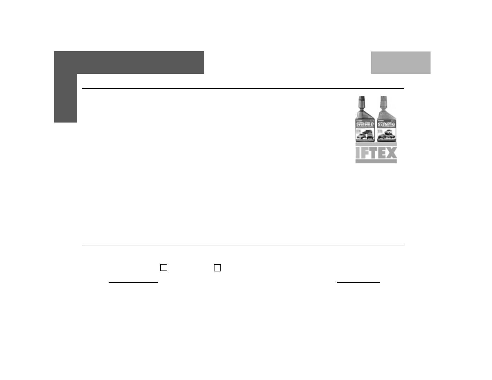
3) Iftex Fuel Additive : System D (For diesel) and System G (For Petrol)
4) Car detailing programming : Exterior Enrichment and Interior Enrichment Program
These products shall help maintain optimum vehicle performance and shall enhance vehicle life.
We have tied up with best in the Class companies, who would bring you the above world class products at
affordable prices. The above products are available with all our Dealers, TASCs and TASPs.
Our Dealer Service marketing executive shall explain to you the benefits of the above mentioned products.
9
Page 10

EXTENDED WARRANTY
T at a Motors recommends the purchase of Extended W arranty,a product of M/s Global Administration Services and
United India Insurance.
Coverage : Mechanical + Electrical + Emission
Benifits :
z Insures you against unforeseen break down repair bills.
z Documentation is simple and hassle free.
z Near cashless & speedy claim settlement.
Term :
z 18 + 18 or 150000 kms whichever occurs first (For Indica, Indigo & Sumo).
z 18 + 30 or 150000 kms whichever occurs first (For Indica, Indigo, Sumo and Safari Dicor).
z 50000 kms + 50000 kms or 36 months whichever occurs first (For Taxis).
z 50000 kms + 100000 kms or 36 months whichever occurs earlier (for T axis-Indica,Indigo,Marina).
EMISSION WARRANTY : Emission warranty is limited to the period of the Extended Warranty or 80,000 kms whichever is earlier.
Extended Warranty available in the dealership from where you have purchased your vehicle. We strongly recommend
purchase of Extended Warranty at time of purchase of your vehicle. Surcharge applicable on purchase of Extended
Warranty after 30 days of purchase of vehicle. The Dealer Service Marketing Executive shall explain to you the Terms
and conditions, Coverage and Owner’s responsibility .
Extended Warranty Booklet & Cover Note :
The Extended Warranty booklet and cover note is the basis of the contract between United India Insurance Co. and the
Owner of the vehicle shown on the Extended Warranty Cover note. The Customer to retain this booklet and the same to be
produced to the dealer while claiming benefits under Extended Warranty .
10
Page 11
EXTENDED WARRANTY
Note :
z The 18 / 30 month extended warranty does not follow the 18 month Manufacturer's warranty.
z The extended warranty comes into force once the manufacturer’s warranty expires e.g. after 18 Months.
z It is more restrictive as by the time it comes into force the vehicle is already 18 months old.
What is covered ?
z Mechanical / Emission / Electrical break down as defined in this warranty and confirmed by the dealer within the stipulated
terms and conditions.
z Tata Motors dealer shall either repair or replace any part found to be defective with a new part or an equivalent at no
cost to the owner for parts or labour.
z Such defective parts which have been replaced will become property of United India Insurance Company.
z Comprehensive list of parts covered is mentioned in the page 9-12 of the Extended Warranty Booklet.
What is not covered ?
Pages 6 – 7 of the Extended Warranty Booklet provided details of the exclusion list.
Owner’s Responsibility :
z Proper use, maintenance and care of the vehicle in accordance with the instructions contained in the Owner’s
Manual and Service Booklet. The records of the same to be ensured in Owner’s Manual.
z Retention of maintenance service bills.
z Always produce extended warranty booklet while servicing & claim in a waaranty ..
I / We have been explained the Terms and conditions, Coverage and Owner’s responsibility by the Dealer Service
Marketing Executive.
I wish to avail / Do not wish to avail extended warranty
Customer’s Sign Dealer’s Sign
11
Page 12
FUEL ADDITIVES
IFTEX: Triple action diesel additive :
One Additive, multiple benefits
z For diesel cars: Iftex System D z For Petrol cars: Iftex System G
Benefits:
z Cleans injector and fuel system.
z Maintains peak engine performance.
z Saves diesel / petrol and maintenance cost.
z Reduces smoke and harmful emission.
z Helps Smooth running of the engine
z Reduces deposit on intake manifold and combustion chamber .
z Reduces deposit on injector tips.
Approved for use in TA T A INDICA, INDIGO, SUMO & SAF ARI
TREA T YOUR CAR TO EXPERIENCE, THE UL TIMA TE PERFORMANCE
Directions of use :
z Remove cap, squeeze lightly till dispenser fills to 10 ml mark. Add before filling up the tank.
z Use at the rate of 1 ml per litre of fuel. For best results, regular use is recommended.
I / We have been explained the Terms and conditions, Coverage and Owner’s responsibility by the Dealer Service
Marketing Executive.
I wish to use / Do not wish to use this treatment
12
Customer’s Sign Dealer’s Sign
Page 13

ANTI RUST , SOUND DEADENING & ENGINE WAXING
Why are Corrosion Protection Waxes necessary?
Corrosion is caused by:
Water / salt water acid rain & atmospheric fallouts.
Critical areas are:
Cavities: joints, crevices, spot welds, underbody
z Corrosion is the most important factor when we talk about the vehicle life. If you treat your car you can
prolong the life.
z It is very dangerous to drive around in a corroded car .
z The corrosion creeps onto the car from the inside and from the outside. The most dangerous kind of
corrosion is often not discovered until it is too late.
Benefits of Anti -Rust treatment :
z A professionally applied range of world class products offering real value to the new and used car customer .
z The treatment has been developed to withstand the harshest environmental and climatic conditions (rst.
Pollutants, stone and gravel impact, etc)
z Insulate cabin space from external noises.
z Expensive tin work and Denting / Painting avoided.
z Higher resale value for the car .
z Higher safety – uncorroded vehicle
z Upto 60 months warranty & 10 free checkups available
13
Page 14

ANTI RUST , SOUND DEADENING & ENGINE WAXING
Engine Wax Treatment :
Engine Wax is a beige coloured transparent lacquer coating on the engine compartment.
z Corrosion Prevention for the Engine compartment
z Neat, clean and New Look to Engine compartment
z No effect on MPFI vehicles
z Engine wax can withstand upto 200 degrees temp
z No need of cleaning the engine compartment with diesel once engine wax is sprayed
z Life of over a year
Sound Deadening System :
Door vibration deadeners - These pads when stuck on the insides of the sheet metal increase sheet metal rigidity,
reduce vibrations and increase riding comfort.
z Used for reducing the sheet metal vibration in a vehicle.
z Product to be used once in the life of the vehicle - Life Time Warranty
z Effect is Life long i.e. until & unless pads are physically removed.
z Negligible increase in Weight & hence no effect on fuel consumption.
z Areas covered - four doors, rear quarter panels & dicky. In case of diesel vehicles, can be used in the bonnet.
Tata Motors has tied up with M/s Wuerth and M/s STS Chemicals (Dinitrol for this world class treatment at affordable prices. This treatment is available in all authorized workshops. The Dealer Service Marketing Executive will
explain to you the benefits and terms and conditions of this treatment.
I / We have been explained the Terms and conditions, Coverage and Owner’s
responsibility by the Dealer Service Marketing Executive.
I wish to avail / Do not wish to avail these treatment
14
Customer’s Sign Dealer’s Sign
Page 15
EXTERIOR AND INTERIOR ENRICHMENT PROGRAM
Vehicle Exterior Enrichment :
Why vehicles are painted?
z For Corrosion protection of the metal surfaces.
z Ease of application from other corrosion protection treatments.
z Cheaper than other corrosion protection methods eg.galvanizing, anodizing.
z For decoration and identification.
Various Environment al Hazards affecting p aint s :
z Environmental hazards: destroy your vehicle's finish.
z Even as your new vehicle rolls off the assembly line, the paint is not protected.
The enemy :
Ultraviolet Rays, Pollution, Tree Sap, Bird Droppings, Car W ash Chemicals, Road Salt, Acid Rain.
Benefits: Vehicle Exterior Enrichment
z Removal of medium scratches, orange peel, oxidation , dust nibs etc & swirl marks from painted surface.
z Restoration of original gloss levels UV protection after gloss is restored.
z Cleaning & dressing of tyres, Bumpers & all exterior plastic moldings/trims.
T at a Motors has tied up with M/s Opulent (W axoyl brand) and M/s 3M for this world class treatment at af fordable
prices. This treatment is available in all authorized workshops. The Dealer Service Marketing Executive will explain to
you the benefits and terms and conditions of this treatment.
15
Page 16

EXTERIOR AND INTERIOR ENRICHMENT PROGRAM
Vehicle Interior Enrichment
Why protect your new car’s fabric interior ?
z Someone will soil your vehicle's fabric carpet or seats.
z A significant detractor from your vehicle's resale value.
z A permanent stain on your vehicle's interior fabric.
The enemy :
Drink Spills - Food S t ains - Mud - Ultraviolet Rays Pets - Traf fic
Benefits: V ehicle Interior Enrichment
z Removal of medium stains and dirt from all interior parts of the car i.e carpet, upholstery and roof lining.
z Cleaning of windshield and all windows (inside and outside)
z Dressing of all internal plastics (eg: door pad trims )and rubber parts.
z The treatment involves cleaning and dressing of All parts of the exposed interiors.
z S pecialised protection for seat fabric from liquid spills.
T at a Motors has tied up with M/s Opulent (W axoyl brand and M/s 3M for this world class treatment at af fordable
prices. This treatment is available in all authorized workshops. The Dealer Service Marketing Executive will explain to
you the benefits and terms and conditions of this treatment.
I / We have been explained the Terms and conditions, Coverage and Owner’s responsibility by the Dealer Service
Marketing Executive.
I wish to avail / Do not wish to avail these treatment
16
Customer’s Sign Dealer’s Sign
Page 17

ENVIRONMENTAL PROTECTION Taking Care of the Environment
T aking care of the Environment
Tata Motors is committed to producing cars using
environmental friendly technology. A number of features
have been incorporated in our passenger cars which are
specifically designed to ensure environmental compatibility
throughout the life cycle of the car. W e would like to inform
you that your car meets Emission norms and is being
regularly validated at the manufacturing stages to keep up
with the stringent emission norms.
As a user you too can protect the environment by operating
your car in a proactive manner. A lot depends on your
driving style and the way you maintain your car. Listed
below are few tips that will help you do so.
WHILE DRIVING :
Avoid frequent and violent acceleration.
¾
Do not carry any unnecessary weight on the vehicle
¾
as it overloads the engine.
Avoid using devices requiring high power consumption
¾
during slow traffic condition.
It is not advisable to warm up the engine during the
¾
first start of the day by idling, as cold temperatures
within the engine could cause rise in the emission
such as CO & HC particulate.
Monitor the car’s fuel consumption regularly . If it shows
¾
a rising trend get the car immediately attended to at
the T A T A MOTORS Authorised Service Centre.
Switch off the engine during long stops at traffic jams
¾
or signals. If you need to keep the engine running,
avoid unnecessarily revving or stopping and starting.
Use only unleaded fuel in petrol cars.
¾
It is not necessary to rev up the engine before turning
¾
it off as it unnecessarily burns the fuel.
For petrol cars switch off the ignition only when engine
¾
is at idling and when the vehicle is stationary , not when
the vehicle is running.
Shift to higher gears as soon as it is possible. Use
¾
each gear upto 2/3rd of it’s maximum engine speed. A
chart indicating gear shifting speeds is given in this
book.
MAINTENANCE OF THE CAR :
Ensure that recommended maintenance is carried out
¾
on the car regularly at the T A T A MOTORS Authorised
Service Outlets.
17
Page 18

ENVIRONMENTAL PROTECTION Taking Care of the Environment
As soon as you notice any leakage of oil or fuel in the
¾
car we recommend that you get it attended
immediately .
Use only recommended brands and grades of
¾
lubricants & coolants and clean/uncontaminated fuels.
Get your vehicle checked for emission periodically
¾
by our authorised dealer and regularly renew the
P.U.C. Certificate.
Ensure that fuel filter, oil filter , breathers are periodically
¾
checked and if required, replace the same using only
genuine recommended brands.
Do not pour used oils or coolants into sewage drains,
¾
garden soil or open streams. Dispose of the used filters
and batteries in compliance with the current legislation.
Do not allow any unauthorised person to tamper with
¾
the engine settings or to carry out modifications on
the car.
Never allow the vehicle to run out of fuel. This will
¾
result in misfiring of the engine and could cause harm
to the catalytic converter .
Parts like brake liners and clutch disc should be
¾
vacuum cleaned. Do not use compressed air for
cleaning these parts which may spread the dust in
the atmosphere.
While carrying out the servicing or repairs of your car,
you should pay keen attention to some of the important
engine aggregates which greatly affect emission. These
components are :-
1. Fuel pump, Injectors / LPG Fuel System
2. Air intake & Exhaust system especially for leakages
3. Cylinder head for valve leakage
4. All filters such as air, oil & fuel filters (check
periodically)
5. Catalytic converter
6. Ignition system - Spark plug gap
This Owner’s Manual & Service Book contains further
information on driving precautions and maintenance care
leading to environment protection. Please familiarise
yourself with these aspects before driving.
18
Page 19

WARRANTY Terms and Conditions
We WARRANT each Tata Indica Xeta
LPG car and parts thereof manufactured
by us to be free from defect in material
and workmanship subject to the following
conditions -
1. This warranty shall be for 18 months
from the date of sale of the car
irrespective of the distance covered.
However, for the cars used for
commercial applications (used for
hire or reward viz those operating
with a yellow number plate), the
warranty shall be limited to 18
months or 50,000 kms, whichever
occurs earlier.
2. Our obligation under this warranty
shall be limited to repairing or
replacing, free of charge, such parts
of the car which, in our opinion, are
defective, on the car being brought
to us or to our dealers within the
warranty period. The parts so
repaired or replaced shall also be
warranted for quality and
workmanship but such warranty shall
be co-terminus with this original
warranty .
3. Any part which is found to be
defective and is replaced by us
under the warranty shall be our
property .
4. As for such parts as tyres,
batteries, electrical equipment, fuel
injection equipment,etc.not
manufactured by us but supplied
by other parties, this warranty shall
not apply, but buyers of the car
shall be entitled to, so far as
permissible by law, all such right s
as we may have against such
parties under their warranties in
respect of such parts.
5. This warranty shall not apply if the
car or any part thereof is repaired
or altered otherwise than in
accordance with our standard
repair procedure or by any person
other than from our sales or
service establishments, our
authorised dealers, service
centres or service points in any
way so as, in our judgement which
shall be final and binding, to affect
its reliability, nor shall it apply if,
in our opinion which shall be final
and binding, the car is subjected
to misuse, negligence, improper
or inadequate maintenance or
accident or loading in excess of
such carrying capacity as
certified by us, or such services
as prescribed in our Owner's
Manual and Service Book are not
carried out by the buyer through
our sales or service
establishments, our authorised
dealers, service centres or service
points.
6. This warranty shall not cover
normal wear and tear or any
inherent normal deterioration of
the car or any of its parts arising
from the actual use of the car or
any damage due to negligent or
improper operation or storage of
the car. This warranty shall not
apply to normal maintenance
services like oils & fluid changes,
19
Page 20
WARRANTY Terms and Conditions
head lamps focussing, fastener
retightening, wheel balancing, tyre
rotation, adjustment of valve
clearance, fuel timing, ignition
timing and consumables like bulbs,
fuel filters & oil filters, etc. This
warranty shall not apply to any
damage or deterioration caused
by environmental pollution or bird
droppings. This warranty shall not
apply to V-belts, hoses and gas
leaks in case of air conditioned
cars.Slight irregularities not
recognised as affecting the
function or quality of the vehicle
or parts, such as slight noise or
vibration, defects appearing only
under particular or irregular
operations are items considered
characteristic of the vehicle.
7. This warranty shall be null and
void if the car is subjected to
abnormal use such as rallying,
racing or participation in any other
competitive sport. This warranty
20
shall not apply to any repair or
replacements as a result of
accident or collision.
8. This warranty is expressly in lieu
of all warranties, whether by law
or otherwise, expressed or implied,
and all other obligations or
liabilities on our part and we neither
assume, nor authorise any person
to assume on our behalf, any
other liability arising from the sale
of the car or any agreement in
relation thereto.
9. The buyer shall have no other
rights except those set out above
and have, in particular , no right to
repudiate the sale, or any
agreement or to claim any
reduction in the purchase price
of the car, or to demand any
damages or compensation for
losses, incidental or indirect, or
inconvenience or consequential
damages, loss of car, or loss of
time, or otherwise, incurred or
accrued.
10. Any claim arising from this
warranty shall be recognised only
if it is notified in writing to us or
to our authorised dealer without
any delay soon after such defects
as covered and ascertained under
this warranty.
11. This warranty shall stand
terminated if the car is transferred
or otherwise alienated by the
buyer without our prior written
consent.
12. We reserve our rights to make
any change or modification in
design of the car or its parts or
to introduce any improvement
therein or to incorporate in the
car any additional part or
accessory at any time without
incurring any obligation to
incorporate the same in the cars
previously sold.
Page 21

INFORMA TION AT A GLANCE Filling S t ation Information
ENGINE OIL UPTO DIPSTICK MAX.MARK ~ 4.0 Ltrs.
FUEL T ANK CAP ACITY PETROL 37 Ltrs.
LPG 31 Ltrs.
* *
* Premixed ready
* *
to use Engine
Coolant = 6 Litres
Windshield Washer
reservior Capacity= 3.5
Litres (for GLX) and 1.5 Litre
(for GL/GLE/GLS/GLG)
Brake fluid = 0.265 Lires
TRANSAXLE OIL 3.3 Ltrs.
IMPORTANT : For petrol cars fitted with catalytic converter always use only unleaded petrol with an octane rating not
TYRE PRESSURE 33 PSI (2.3 bar) / 30 PSI (2.1 bar)
FRONT / REAR
less than RON 87.
For recommended oil grades and change intervals, refer lubricants chart and service schedule
21
Page 22

INFORMA TION AT A GLANCE Dimension s
22
Page 23
INTRODUCTION - LPG
INTRODUCTION - LPG
••
•
••
KNOW YOUR INDICA LPG
••
•
••
St arting the engine
Fuel (LPG) filling
Running on LPG
Fuel Selector Switch
Shifting the fuel mode
Do’s and Dont’s
SAFETY
••
•
••
In case of gas leakage
Fire Extinguisher
Manual shut off knob / lever
Level Indicator
COMPLIANCE TO MOTOR VEHICLE RULES
••
•
••
LOCATION OF LPG SYSTEM COMPONENTS
••
•
••
LOCA TION OF FUSES
••
•
••
23
Page 24

INTRODUCTION
In addition to the full capacity of petrol the Indica Xeta now
comes with LPG as additional fuel choice.
WHAT IS LPG?
LPG or Liquefied Petroleum Gas is a safe and environment
friendly fuel. It is a liquid under pressure and turns into
gaseous state when exposed to the atmospheric pressure.
LPG is a non-toxic, non-corrosive; lead-free gas and is
produced by refinery fractionation of oil or is stripped from
naturally occurring Natural Gas.
LPG fuel system and the components are as safe as those
in other fuel systems.
For LPG operation, press the Fuel Selector Switch provided
on the dashboard, for approximately 3 seconds. The fuel
change over happens automatically .
The switching between fuels (Petrol-LPG-Petrol) can be done
at any time, even on the move.
Your car always starts in petrol / auto mode only. Hence it
is a must to have petrol at all times during running.
WARNING
DO NOT USE DOMESTIC GAS CYLINDERS IN CAR
because…
• Domestic cylinders are NOT designed for Car
application and this makes them vulnerable in a crash
situation.
• The chemical composition of domestic LPG is different
from that of Auto LPG, which may lead to premature
failure of engine and its related components
• The gas outlet ‘valve’ arrangement on the domestic
cylinder doesn’t meet the car fuel supply standards
and hence makes them more dangerous in the car.
For example the valve is not provided with excess flow
protection.This means that if the valve or supply line
gets disconnected in a crash situation, there will be an
uncontrolled flow of LPG into the car interior.
• When using domestic gas cylinder, your car’s engine
gets less supply of fuel when load on engine is
increased (e.g. while climbing a ghat). This is because
the cylinder cannot supply adequate LPG from the tank
to the engine.
24
Page 25
ST ARTING THE ENGINE
Irrespective of the position of the Selector switch (Petrol
or LPG), your car’s engine will always starts using petrol
by default and switch over to LPG later incase of LPG
mode.
To start, turn the ignition “ON” and crank without pressing
accelerator pedal.
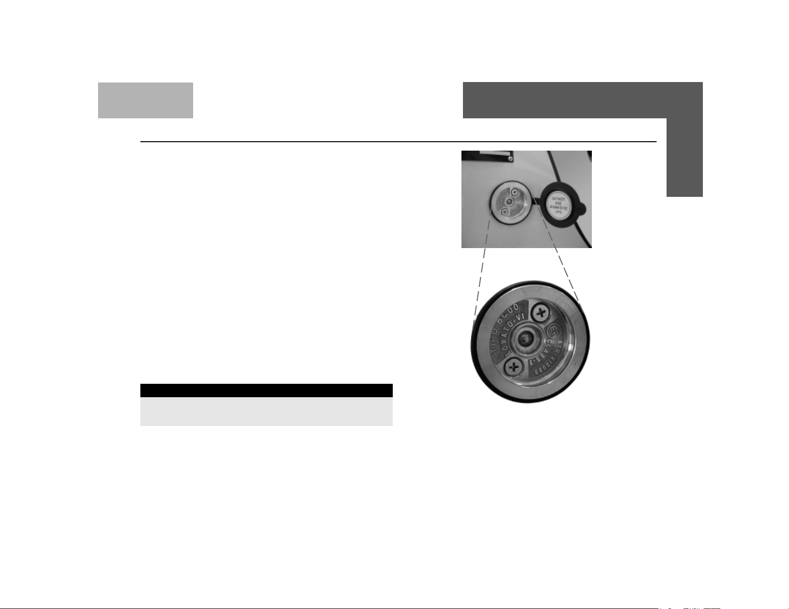
LPG FILLING
LPG filler valve is located at the rear on the right hand body
side of your car. LPG filling will stop automatically once the
LPG tank is filled to 80% of its capacity.
LPG TANK CAP ACITY
The LPG cylinder capacity of your car is 31 litres. If the
LPG is filled after service / repairs of the LPG system, please
check all joints for leakage by applying soap solution or by
using an electronic instrument, (Example: Leakator - 10’).
NOTICE
Keep the Ignition switch in “OFF” condition during
LPG refilling
KNOW YOUR INDICA LPG
LPG Fuel Filling Cap
PETROL T ANK CAP ACITY
Your car has a petrol tank having a capacity of 37 litres
25
Page 26

KNOW YOUR INDICA LPG Running on LPG
RUNNING ON LPG
A Fuel Selector Switch is provided on the dashboard. By
operating this switch you can choose your fuel option for running.
The Fuel Selector Switch has following functions :
1. Fuel mode request (Petrol, LPG).
2. LPG level indication
3. Fuel mode indication
4. LPG System fault indication
The Fuel Selector Switch has two modes :
Fuel Selector Switch
1. Petrol Mode : The Red LED comes ON
2. LPG Mode: The Amber LED comes ON
In Petrol Mode Engine starts and runs by using petrol as the fuel.
In LPG Mode, the engine starts by using Petrol and switches to
LPG automatically .
IMPORTANT
Ensure that your car has sufficient Petrol in the tank as petrol
is used for starting always
26
LPG
( Amber)
Petrol Mode : Only Red light is ON
LPG Mode : Amber light is ON
Green
Fuel Selector Switch
PETROL
( Red )
Page 27

KNOW YOUR INDICA LPG Fuelling Modes
HOW TO SHIFT THE FUELLING MODES :
Petrol to LPG Mode :
Y ou can switch to LPG fuel mode by pressing and holding
the Fuel Selector Switch at least for 3 seconds till the LED
on the Switch starts toggling between two LEDs. On
completion of the successful transition to the LPG mode,
the Amber (LPG) LED glows permanently, indicating that
the car is now in LPG mode
LPG to Petrol Mode:
Similarly you can switch from LPG to petrol mode by
pressing the Fuel Selector Switch until the red light (Petrol)
on the Fuel Selector Switch starts glowing permanently.
This indicates that car is now running in petrol mode
Sr.No. Approximate LPG LED indication on Change Equivalent quantity
Volume (Litres) Over Switch (COS) of LPG in tank (%)
1 Up to 1 1 Litres Amber Below 25%
2 12 - 15 Litres Amber + 1 Green LED 25%
3 16 - 20 Litres Amber + 2 Green LED 50%
4 20+ Litres Amber + 3 Green LED 80%
NOTICE
1. In case of fuel mode switching from Petrol to LPG
mode during normal running, initially the LEDs toggle
indicating the transition and when the LED glows
permenantly, this indicates the completion of the
transition to the required fuel mode.
2. Fast toggling of the LEDs (amber to red) indicates
fault in the LPG system. Car will automatically switch
to Petrol mode. Please get car checked/repaired at
the nearest Authorised T ATA service center.
3. Very slow toggling of the LEDs (amber to red) indicates
the empty tank / no LPG supply (loss of pressure).
Get the LPG tank re-filled.
27
Page 28

KNOW YOUR INDICA LPG Do’s & Dont’s
DO’S
• Always get the car repaired/serviced at the Authorised
T ATA Service center only .
• Never carry out any repair work on your own or from
any other personnel other than from Authorised T A TA
Service center.
• Check LPG fuel system periodically for leakages
Even though the Safety Solenoid valve (on tank &
pressure regulator) closes automatically when you switch
off Ignition, it is recommended to close the manual
service valves during any service/repair activity on the
car.
• Ensure adequate ventilation around the car during repair
works.
• Ensure the LPG in the pipe lines is consumed by running
the engine with closed manual service valves before any
repair work on the gas lines/joints.
• Remove the LPG tank during the welding/brazing work
on the Car.
• Fast toggling of fuel mode LED’s on the Fuel Selector
Switch means fault in the LPG system, please get the
car repaired at the nearest Authorised TATA Service
center.
• Immediately repair/replace any damaged fuel or system
component.
• Use the fire extinguishers provided with the car in case
of unlikely event of fire. These are provided, one near
driver seat and the other one in the boot. Read
instructions on Fire extinguisher to know how to use it.
DON’TS
• Over filling the LPG Tank can cause safety issues
like gas leakage . Please DONOT over fill the tank
beyond its capacity of 31 litres.
• Keep the car away from any Fire source.
• Never use naked flame/fire to check gas leakages.
• Never carry out any welding/brazing on the LPG tanks.
• Avoid direct contact with LPG as it may cause frost
burns.
• Wash instructions - Do not direct high pressure washer
fluid/water jets at electrical devices & their connectors
during washing. This is to prevent malfunction / failure
of electrical system due to water ingress.
• Do not tamper any electrical or mechanical settings.
• Do not scrap / gas cut the LPG cylinder as it contains
pressurised gas which is flamable.
• Do not leave the LPG tank cover open.
For any clarifications please contact the Authorised
T A T A Service center
28
Page 29
KNOW YOUR INDICA LPG Safety
IN CASE OF GAS LEAKAGE :
• Do not panic.
• The ECU automatically switches-off the LPG supply from
the tank.
• As a safety precaution, close the manual shut - off valves
provided on the ‘Multifunction valve’ located on the LPG
tank. Ensure that the tank cover is properly fitted.
• Roll down all the windows and keep the doors fully open.
• The ECU will automatically switch the fuel mode to Petrol.
• The ECU will not allow you to switch to LPG mode until
the leakage is rectified.
• Contact the nearest Tata Authorised service station and
get car repaired.
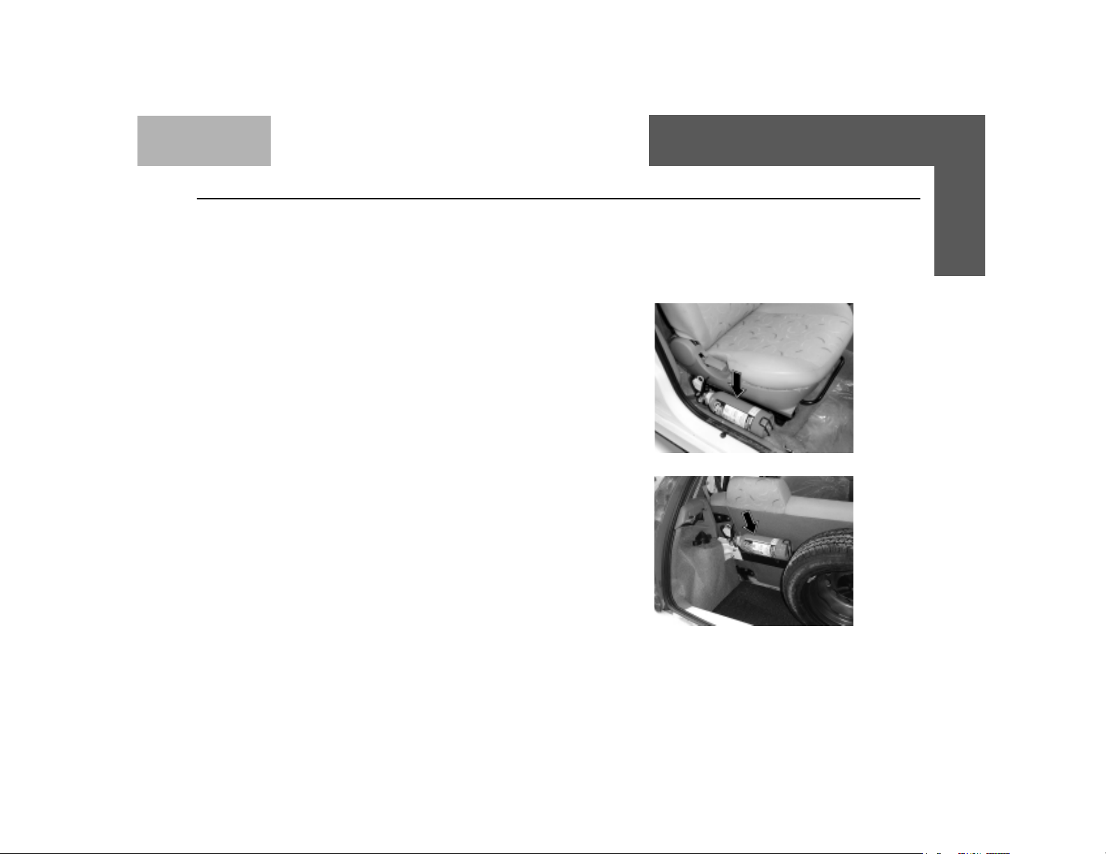
FIRE EXTINGUISHER :
Two fire extinguishers are provided on the car, one near
driver seat and another in the luggage compartment.
Method of operation:
1. Check if the pressure gauge needle in green zone.
2. Hold upright and pull the pin.
3. Press the lever.
4. Direct discharge at base of flame with rapid sweeping
motion.
5. Recharge the fire extinguisher after use.
Maintenance :
Check pressure on the gauge every week, needle should
remain in green region. If it comes to red region, please
send for recharging. The Fire Extinguisher is to be
refilled every three years even if it is not used.
Fire extinguisher near Driver's Seat
Fire extinguisher behind Rear Seat
29
Page 30
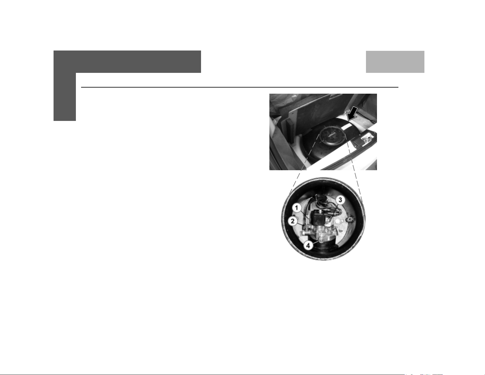
KNOW YOUR INDICA LPG Safety
MANUAL SHUT OFF KNOB / LEVER
This knob is used to shut OFF LPG flow & is located on the
Multifunction valve, on the Auto LPG T ank. This valve should
always be in open position (as per figure), so that there is
unrestricted flow of LPG to the engine. When the valve is in
the closed position, LPG flow to the engine is stopped.
This shut off valve must be closed in case some repairs
need to be carried out on the LPG Tank. Ensure that the
tank’s cover is tightened /closed properly.
LEVEL INDICA TOR
A multivalve is mounted on the LPG tank that also has a
gauge that shows LPG level in the tank. LPG level can also
be known by the three green coloured lights on the Fuel
Selector Switch. When the LPG tank is full, all three green
lights will glow. As the level of LPG goes down, the green
lights will also go off one by one.
NOTE : The LED indication is an additional indication of LPG
quantity in tank.
30
LPG T ank
1. Inlet
2. Outlet
3. Level Indicator (Dial type)
4. Manual Shut Off Valve
Page 31

KNOW YOUR INDICA LPG Compliance to Motor Vehicle rules
Y our car’s LPG tank needs to be recertified every five years
as per CMVR (AIS 24, 25 and 26)
Please ensure that it is done by a TATA Authorised
Service Outlet and the new date is engraved on the
plate.
31
Page 32

KNOW YOUR INDICA LPG Location of LPG system components
32
Page 33

CONTROLS
••
•
••
INSTRUMENT P ANEL
••
•
••
HEA TING , VENTILA TION &
••
•
••
AIR CONDITIONING
INTERIORS & ACCESSORIES
••
•
••
Rear View Mirrors
Sunvisors
Glove Box
Window Winding
Power Windows
Tray Cover with Coin Holder
Plug Socket
Rear Ashtray
Digital Clock
Roof Mounted Interior Lights
Front Seat & Seat Adjustments
BEFORE DRIVING
Head Rest
Rear Seat
Seat Belt Adjustment
T ailgate Opening
Fuel Flap Opening
Music System
Electrical Accessories
Fitment
Load Area Lamp
Front Fog Lamps
Head Lamp Leveling Switch
33
Page 34

BEFORE DRIVING Controls
34
Page 35

BEFORE DRIVING Controls
Keys :
Your car comes with two identical keys.
With this key, you can operate 1.Door Locks
2.Steering Lock cum ignition switch
3.T ail gate Lock 4. Glove box
It is advisable to keep one of the keys in a safe place for use in
case of an emergency .
Do not use a locally made key, but obt ain a duplicate through
your T at a Motors dealer.
Do not leave the key inside the car.
Door Locks :
The front doors can be locked and unlocked from outside with the
key or from inside using the door lock lever. In your car , the driver's
door & co-driver's door have separate locking facilities. T o lock from
inside turn the lever towards the inner hinged handle.
Where the central locking system is provided, if you lock/unlock
the driver door with the key , the remaining three doors get locked/
unlocked at a time. The tail gate door is not a part of the central
locking provision.
T o open the door from outside use the swing handle. After unlocking
the door with the key, pull the swing handle upward. The swing
handles are provided on each door.
T o open the door from inside pull the hinged handle outward.
Lock Unlock
Hinged handle
T o open
Outside swing handle
Locking /
Unlocking
lever
T o open
Inside door handle
35
Page 36

BEFORE DRIVING Controls
IN CASE OF EMERGENCY
1) The electirically operated devices (like central locking, power
window) may malfunction in the event of flood/fire, due to temporary
or permanent damage to the device. Excerise approriate
precautions for safety of yourself and other occupants.
2) If the central locking system malfunctions and is unable to unlock
doors electrically, the door can still be opened by manually
unlocking knob '1' and opening the door using lever '2'. The
mechanical system overrides the electrically operated system.
Childproof Lock :
Both the rear doors of the car are provided with childproof locks.
Push the lock lever located on the vertical face near the rear lock
downward before closing the door. The door which has been locked
can no longer be opened from inside.
When child lock on rear door is 'LOCKED', the door can only
be opened from outside. Use front doors to exit or take help of
front occupants
Deactivate the childproof lock when not required.
36
Page 37

BEFORE DRIVING Controls
Steering lock cum ignition switch :
The steering column lock cum ignition switch has the
following four positions and is operated with the key .
1. LOCK POSITION - The key can be inserted or taken out
only in this position. When the key is removed from the
switch, the steering is locked. To unlock the steering,
insert the key and also turn it to the 'OFF' (Steering unlock)
position.
2. 'OFF' POSITION - In this position, the steering lock opens
and the music system is powered.
Ignition SwitchIgnition Switch
Ignition Switch
Ignition SwitchIgnition Switch
3. 'IGN' POSITION - This is for switching 'ON' the power
supply to the following items :
• Blower & A/C (if fitted)
• Engine cooling fan
• Horn
• Power Socket
• Power window (if provided)
• Head Lamp Leveling Switch
• Head lamps
• Front fog lamps (if provided)
• Load Area Lamp
• Music system (if provided)
• Digital clock
• Engine ignition & fuel supply
• Turn signal lamps
• Wash and wiper system
• Reverse light
• Instruments and gauges and tell tale warning lamps
• Audio warning unit
• Fog Lamps
4. 'START' POSITION - In this position, which is
momentary, the switch cranks the engine. When the
switch is in this position momentarily , the devices listed
under "Accessories supply" above, are switched 'OFF'.
37
Page 38

BEFORE DRIVING
The following items are operated/powered without the key in
the ignition switch :
Hazard warning system, Stop lamp s, Position lamps, Registration
plate lamps, Illumination of A.C. control panel, Odometer display
(LCD) of Instrument Panel, Roof lamp, Reading lamps, Engine
lamp,Load Area Lamp, Central door locking, Audio warning unit,
Memory of digital clock and Music System, Rear Windshield
Demister.
The switch symbol lamps may come 'ON' without the key in the
'IGN' position on ignition switch.
Note : When the key is returned from 'OFF' position to LOCK
position, the music system continues to be powered until the
key is removed from the switch. This also helps to remind the
driver if the key is inadvertantly left in the vehicle when aligting
from the vehicle, where this is provided.
I) Do not remove the key, while the car is in motion, as the
steering will get locked and the car cannot be steered.
II ) While turning the key from `LOCK 'position to `OFF'
position slightly rotate steering wheel to relieve pressure
on steering spindle for easy operation of the key. Also
ensure the key is inserted fully before turning the key .
iii) Do not operate to START position when the engine is
running. This may damage the ring gear of the starter
motor.
Controls
38
Page 39

BEFORE DRIVING Controls
Combi-switch
FLICK WIPE
SPRING RETURN
OFF
FAST WIPE
SLOW WIPE
PUSH SWITCH
FOR WASH & WIPE
OFF
INT. WIPE
DELAY TIMING FOR
INTERMITTENT WIPE
WIPER STALK LIGHT STALK
OFFOFF
OFF
OFFOFF
MIN.
MAX.
OFFOFF
OFF
OFFOFF
FLASH HIGH BEAM
SPRING RETURN
DIP BEAM
(NORMAL
POSITION)
HIGH BEAM
LEFT TURN
(SIGNAL SELF CANCELLING)
LANE CHANGE LEFT (SPRING RETURN)
OFF
LANE CHANGE RIGHT (SPRING RETURN)
RIGHT TURN
(SIGNAL SELF CANCELLING)
LIGHTS CONTROL
SWITCH
39
Page 40

BEFORE DRIVING Controls
WIPER CONTROL COMBI-SWITCH LEVER - LEFT
CC
C
CC
BB
B
BB
EE
E
EE
AA
A
AA
FF
F
FF
DD
D
DD
Wiper Control Combi-switch Lever - Left
A. Wiper 'OFF' position
B. Slow Wipe
C. Fast Wipe
D. Intermittent wipe *
E. Pull up for windshield wipe
(Flick Wipe Spring Return)
F. Press side knob for wash
* Rotate selector to set delay timing for intermittent wipe
SelectorSelector
Selector
SelectorSelector
LIGHTS CONTROL COMBI-SWITCH LEVER - RIGHT
GG
G
GG
FF
F
FF
CC
C
CC
BB
B
BB
DD
D
DD
EE
E
EE
AA
A
AA
HH
H
HH
II
I
II
Lights Control Combi-switch Lever - Right
A. Head lamp 'OFF' position
B. Position lamp 'ON'
C. Position lamp & head lamp 'ON'
D. Push down the lever for high beam
E. Pull up the lever (spring return) for high beam flash
F. Lane change left (spring return)
G. Side Indicator - LH
H. Lane change right (spring return)
I. Side Indicator - RH
40
Page 41

BEFORE DRIVING Controls
Fog lamps : (if fitted)
Front and Rear fog lamps can be switched ON/OFF by operating
the switch on the Combi-Switch.
Front fog lamp : Rotate the switch clockwise to switch 'ON' the
fornt fog lamp. Front fog lamps are operative only when the position
lamps are switched 'ON'. Rotate the switch to same direction to
switch 'OFF' the front fog lamp.
The indicator on the instrument cluster comes 'ON' when the front
fog lamps are switched 'ON'.
Rear fog lamp : Rotate the switch anticlockwise to switch 'ON' the
rear fog lamp. Rear fog lamps are operative only when the head
lights are swithed 'ON' or front fog lamps are switched 'ON'. Rotate
the switch to same direction to switch 'OFF' the rear fog lamp.
The indicator on the instrument cluster comes 'ON' when the rear
fog lamps are switched 'ON'.
Selector
Selector
41
Page 42

BEFORE DRIVING Controls
Accessory Switches : (if installed)
Accessory switches have been provided on the dash board
near the steering column on the right hand side.
1. Rear windshield demister (unlatched
switch)
The switch is pushed and released to switch
'ON' and the knob returns to the normal
position.The function indicator lights up in amber
indicating that the demister heater is 'ON'. The function
is controlled through a timer and operates for 15 minutes
(approximately) and goes 'OFF' automatically at the end
of the duration. The heater can be switched 'OFF' anytime
by once again pushing and releasing the switch knob.
Note : Switching 'ON' and 'OFF' can be done only with
key in 'IGN' position. The demister heater remains 'ON'
even after removal of ignition switch key and goes 'OFF'
at the end of 15 minutes period, In case you are missed
to switched 'OFF'.
2. Rear windshield wiper (latched switch)
Push to switch 'ON' - Push to switch 'OFF'
The function indicator on the knob lights
up in green when the wiper function is 'ON'.
3. Rear windshield wash & wipe (unlatched switch):
Push and hold the switch knob for the
operation of the wash function on the rear
windshield glass for rear visibility through
glass. The function indicator lights up in
green when wash function in 'ON'. Along with
the wash fluid getting sprayed, the wiper also operate
with a delay to wipe the glass surface, through timer
control unit.
Accessory SwitchesAccessory Switches
Accessory Switches
Accessory SwitchesAccessory Switches
42
Page 43

BEFORE DRIVING Controls
Gearshift lever & Shifting pattern :
The gearshift lever is mounted on the central console between the
two front seats. The gearshift pattern is shown on the gear lever
knob.
The reverse gear should be engaged only when the car
is stationary. Wait for 5 seconds after declutching to
ensure smooth engagement of the reverse gear.
Parking brake :
A mechanical parking brake acting only on the rear wheel is provided
on your car. The parking brake lever is located behind the gearshift
lever. To apply the parking brake, pull the lever up fully . The indicator
light on the instrument panel will come `ON'. To release it,
pull the lever up slightly, press the release button and push the
lever down.
The parking brake indicator on the instrument panel will go
'OFF' when the parking brake lever is fully released.
When parking on level ground, place the gear lever in the 'Neutral'
position. When parking on a downhill gradiant, place the gear lever
in 'Reverse' position. When parking on uphill gradiant, place the
gear lever in the '1st' position
Apply the parking brake properly before leaving the car &
release it before moving. Use the parking brake for holding
the car on a gradient.
ReleaseRelease
Release
ReleaseRelease
ButtonButton
Button
ButtonButton
Parking Brake LeverParking Brake Lever
Parking Brake Lever
Parking Brake LeverParking Brake Lever
43
Page 44

BEFORE DRIVING Instrument Panel
INSTRUMENT P ANEL
Speedometer
Temperature Gauge
Set Knob Mode Selector
* All indicators may not be provided on some clusters.
Indicators*
LCD
Knob
Engine RPM
Meter
Fuel Gauge
44
Page 45

BEFORE DRIVING Instrument Panel
T urn Signal and Hazard Warning
I) Turn Signal :
Turn signal lamps can be operated only when the ignition supply
is 'ON by using the turn indicator switch on the combiswitch.
The direction indicator (LHS) and (RHS) on the instrument
cluster flashes along with external indicator lights as selected.
II) Hazard Warning :
This can be operated without ignition 'ON'. Press the hazard
warning switch (red knob) on the centre of the dash board, all
side indicator lights and indicator , LHS and RHS turn
indicators on the instrument cluster will flash simultaneously to
warn the other road users about any hazardous condition of
the car. Depress the knob again to switch 'OFF' the hazard
function.
Note : If light does not blink or blinks rapidly , it is an indication
of fault in the blinker electrical system or the indicator bulb at
front or rear has fused. Get it rectified immediately .
Hazard Warning SwitchHazard Warning Switch
Hazard Warning Switch
Hazard Warning SwitchHazard Warning Switch
45
Page 46

BEFORE DRIVING Indicators
Parking Brake Indicator cum Low Brake Fluid Warning Light
When the ignition key is turned to the 'IGN' position, the symbols
light up for the following :
i) when the parking brake is applied, and/or
ii) when the brake fluid level in the container is low.
Else the indication goes 'OFF' after few seconds.
If the lamp glows while engine is running, then check the parking
brake or brake fluid oil level.
Do not drive the car if this indicator remains 'ON'. Get the
problem attended to immediately at an Authorised Service
outlet.
High Beam Indicator :
Symbol lights up when the headlamp high beam is 'ON'.
Engine Check Indicator :
This lamp indicates engine condition. When a malfunctioning occurs
in Engine or EMS, this lamp indicates as below :
1. Remains "OFF" in "IGN" position.
OR
2. Remains "ON" in running position.
46
Page 47

BEFORE DRIVING Indicators
Position Lamp Indicator :
Symbol lights up when the position lamps are switched 'ON'.
Illumination lamps for AC, HVAC or ventilation panel and switch
illumination lamps comes 'ON', when the position lamps are 'ON'.
Position lamps can be used as parking lamps.
Instrument cluster illumination turns 'ON' with key in 'IGN' position
and position lamps 'ON'.
Note : Position lamps also remain 'ON' while head lamps are
'ON' and in this condition instrument cluster illumination lamp
will not be 'ON'.
Low Oil Pressure Indicator :
When the ignition key is turned to the 'IGN' position, symbol lights
up and goes off as soon as the required engine oil pressure is
developed after starting the engine.
If the low oil pressure indicator does not glow or remains
'ON' with the 'IGN' on and engine is running, it indicates a
fault in the electrical circuit/lubrication system. Check &
get the problem attended to at an Authorised Service outlet.
47
Page 48

BEFORE DRIVING Indicators
Battery Charging Indicator :
Symbol lights up when the 'IGN' is turned 'ON' and should go 'OFF'
after the engine starts.
If it remains 'ON' while the engine is running, it indicates
that the battery is not being charged. Switch off all
unnecessary electrical equipment and get the problem
attended to at an Authorised Service outlet.
Front Fog Lamp Indicator (if provided) :
This symbol lights up when the front fog lamps are switched 'ON'
Rear Fog Lamp Indicator (if provided) :
This symbol lights up when the rear fog lamps are switched 'ON'
48
Page 49

BEFORE DRIVING Gauges
Speedometer , Main Odometer and Tripmeter (on LCD) :
The speedometer indicates the car speed in km/hr. The odometer
records the total distance the car has been driven. The tripmeter can
be used to measure the distance travelled on each trip or between
fuel fillings.
Keep track of the odometer reading & follow the maintenance
schedule regularly for meeting service requirements.
Odometer, Tripmeter and Illumination intensity control on
instrument panel (LCD) :
The instrument panel has an LCD to display the following :
Main Odometer (Non- resettable)- Counts upto 999999 kms
Tripmeter A (Resettable) - Counts upto 1999.9 kms
Tripmeter B (Resettable) - Counts upto 1999.9 kms
Intensity level of instrument panel illumination - selection among preset
levels.
LCD has two line display .The first line displays the Odometer count.The
second line displays either of Tripmeter A, T ripmeter B, Intensity level
of panel illumination.
The selection and control of functions are done through 'MODE' and
'SET' push buttons (knobs) provided on either side of the LCD.
The 'MODE' knob is used to select one of Tripmeter A, T ripmeter B or
Intensity level of panel illumination. Switching among the above three
functions can be done by pressing the knob.
Over speed warning indicator
Speedometer
Display for Trip - A
Display for Trip - B
49
Page 50

BEFORE DRIVING Gauges
The 'SET' knob is used to control the chosen function. Pressing the
knob for a few seconds resets the chosen tripmeter and varies the
intensity level of instrument panel illumination.
The panel illumination intensity varies among preset levels as follows :
= Min
= = = = Max
This display returns to Trip A after a few seconds of intensity level
selection, if left in this mode.
NOTICE
Main odometer and tripmeter A indication will remain on display
even if the ignition key is removed.
Reduced contrast in display may occur at low and high temperature.
Over speed warning indicator (if provided) :
When the vehicle speed reaches more than 120 kmph, over speed
warning indicator will come 'ON'.
50
Intensity Level Indicator
Over Speed Warning
Indicator
Page 51

BEFORE DRIVING Gauges
RPM meter :
The meter indicates engine speed in revolutions per minute (rpm)
Change gears at appropriate engine rpm and car speed to get optimum
fuel economy .
The permitted engine rpm upper limit is the start of Red Zone on the
dial.
If RPM meter does not indicate during initial cold starting, gently raise
the engine rpm till the battery charge lamp goes 'OFF'.
T emperature gauge :
The gauges indicates the temperature level of the engine coolant. The
red zone at 'H' indicates temperatures higher than normal. A visual
warning indication (Red coloured) comes 'ON' indicating that when
the coolant temperature is higher than normal.
Avoid driving, when the pointer is in the red zone. It indicates engine
overheating, which may be due to insufficient coolant in the radiator
or due to any other defect. Take the car to the nearest Authorised
Service outlet for necessary attention.
Never remove the cap from the coolant reservoir when the
engine is hot. Do not restart the engine until the problem has
been duly attended.
RPM Meter
Temperature Gauge
High
Temperature
Warning
51
Page 52

BEFORE DRIVING Audio Warning
Fuel Gauge :
The fuel gauge indicates the approximate fuel level in the tank.
Refill the fuel tank at the earliest, when the needle touches the red
band (indicating reserve capacity has been reached.), a visual
warning indication (Amber coloured) comes 'ON' indicating the
fuel level is low .
Audio Warning Unit
Seat Belt Reminder (Beeper) : (If installed)
When the key is in the 'IGN' position and the driver's seat belt has
not been fastened, an audio warning comes 'ON'. Please fasten
the seat belt. The warning goes 'OFF' automatically after a few
seconds, even if the seat belt is not fastened.
'Key in' Warning Beeper : (if installed)
When the ignition is turned to 'OFF' position and the key is not
removed from the switch, an audio beep comes on if driver door is
open. The beeper will go 'OFF' after a few seconds automatically if
warning is ignored or if the key is removed/door is closed.
WW
W
WW
LowLow
Low
LowLow
FF
ueluel
F
uel
FF
ueluel
arar
ningning
ar
ning
arar
ningning
FF
uel Guel G
F
uel G
FF
uel Guel G
augeauge
auge
augeauge
52
Page 53

BEFORE DRIVING Audio Warning / Tail Lamps
Lamps 'ON' Reminder (if installed)
An audio warning (beeper) is provided to inform the driver that the
headlamps/position lamps are left 'ON'. This comes 'ON' when the
driver removes the key and opens the door. Switch 'OFF' the lamp s,
before leaving the car. However the lamps can be kept 'ON' ignoring
the warning, if desired.
T ail Lamp : The tail lamp assembly incorporates the following-
1. Stop cum position lamp
2. Turn Indicator
3. Reverse Lamp
4. Fog lamp (provided in Deluxe version only)
5. Reflex reflector
Registration Plate Lamps :
Two concealed lamps are provided for illumination of the rear
registration number plate.
High Mounted Stop Lamp :
High mounted stop lamp is provided at the rear of vehicle and it
glows whenever the service brake is applied.
High Mounted Stop Lamp
Registration Plate Lamps
53
Page 54

BEFORE DRIVING Heating, Ventilation & Air Conditioning
Air Flow Pattern
T owards Windscreen (Defrost)
Side Air
Vents
Central
Air Vents
Towards
Foot Board
Towards
Foot Board
54
Page 55

BEFORE DRIVING Heating, Ventilation & Air Conditioning
HEA TING , VENTILA TION & AIR CONDITIONING
(if installed)
A. Temperature Control Knob :
The air temperature in the car can be controlled by operating
the temperature control knob (A) at the left hand side of the
control panel. The temperature can be increased by rotating
the knob towards the red segment and decreased by rotating
it towards the blue segment.
B. Blower Speed Regulation Knob :
The ventilation system has a three/four speed blower. The
blower speeds can be regulated to any one of the following
speeds by operating the knob (B) at the centre of the control
panel.
LOW • MEDIUM • HIGH • VERY HIGH
D
A C
B
HVAC CONTROLS
E
55
Page 56

BEFORE DRIVING Heating, Ventilation & Air Conditioning
C. Air Direction Control Knob :
The air flow can be changed by turning the switch (C) to
the desired direction.
T owards face
T owards face and feet
T owards feet
T owards feet and windshield
(Recommended for clearing fogging on windshield)
Air demist / defrost windshield
(Recommended for clearing heavy fog and snow)
D. A.C. ON/OFF Switch :
The A.C. can be switched 'ON' by pressing the switch (D)
on the A.C. control panel provided the blower is `ON' and
the engine is running. The indicator lamp will show that the
A.C. is `ON'.
D
Indicator
AA
A
AA
A.C. CONTROLS
BB
B
BB
D
CC
C
CC
56
A.C. ON / OFF Switch
Page 57

BEFORE DRIVING Heating, Ventilation & Air Conditioning
E.Air Circulation Switch :
• In HVAC version to put air circulation mode in
recirculation, press switch 'E'. The indicator lamp will
show air circulation is in recirculation.
T o put vehicle in Fresh mode release switch 'E'. Indicator
lamp will be 'OFF'.
• In A.C. version, air circulation mode can be selected
by rotating knob 'E'.
Fresh Recirculation
• In recirculation mode, air inside the vehicle is circulated
again and again. In Fresh mode, air is taken from
atmosphere and circulated in the vehicle.
Recirculation mode can be used
• While driving in dusty condition
• To avoid traf fic pollution
• To get quick cooling/heating as required.
Whenever discomfort is felt switch air circulation mode to
fresh.
Notice : The A.C. can be switched `ON' only if the blower
is 'ON' and engine is running. When A.C. is switched
'ON' engine idling RPM increases marginally, to adjust
to the A.C. compressor load. When desired temperature
is achieved A.C. trips 'OFF' automatically.
E
Indicator
Air Recirculation
Knob
Notice : The A.C. compressor gets switched 'OFF'
automatically when engine gets overheated. The A.C. is
automatically switched 'ON' when the engine cools down.
Normal Cooling :
A.C. - ON
Knob 'B' - Desired speed position
Knob 'C' - T owards face
Switch 'E'- Suitably as explained
Quick Cooling :
If your car is left in the sun with window closed inside
temperature increases.
57
Page 58

BEFORE DRIVING Heating, Ventilation & Air Conditioning
To achieve quick cooling effect, open the windows briefly
while you operate the air conditioner, with air circulation
switch is in Fresh mode, fan at higher speed and air direction
towards 'FACE'. All vents to be opened completely .
Once temperature inside has come down sufficiently , close
the windows and change air circulation suitably to fresh/
recirculation.
Demisting :
In rainy season or in areas of high humidity , mist formation
inside windshield glass is observed. To clear mist
dehumidified air is passed on the windshield glass.
The position of control knobs should be adjusted as follows:
A.C. - ON
Knob 'B' - Desired speed position
Knob 'C' - T owards windshield
Knob 'A' (for vehicles fitted with HVAC) - at suitable
temperature
Air circulation - at suitable position
Notice : When mist gets cleared switch the knob "C'
position to Face mode.
In high humidity areas, if cold air continues to flow over
windshield, it may cause sudden fogging on outside
surface of windshield.
Defrosting :
(For vehicles fitted with HV AC unit)
In low temperature areas, to clear frost formation outside
the windshield glass, this setting is used.
First start the engine and accelerate to warm up.
Knob 'A' - Maximum hot position
Knob 'B' - V ery High
Knob 'C' - Towards windshield
Switch 'E' - Fresh air mode condition
Once the windscreen has become clear, move the fan switch
to desired speed.
Notice : Electric heater coil is provided for demisting of
tail gate glass for deluxe versions.
Normal Heating :
( For vehicles fitted with HV AC )
Knob 'A' - Suitable temperature position
Knob 'B' - Suitable blower speed
Knob 'C' - Towards face & feet
A.C. - OFF
Air Circulation- Fresh switch
58
Page 59

BEFORE DRIVING Heating, Ventilation & Air Conditioning
Quick Heating :
All settings as explained before except air circulation switch
to recirculation.
Once vehicle is heated, switch back to fresh mode.
CLOSE
OPEN
Ventilator :
The air flow can be adjusted continuously with the rotary
control knob at the vents on the dash board. The air vents
can be adjusted upward and downward. This is common
for HV AC, AC and ventilation.
Notice : Refrigerant charged in the air conditioning
circuit has been identified on the label over front body
member. Use only refrigerant as given in the label for
topping up or recharge, i.e. do not charge R12 (CFC) in
the vehicle earlier charged with R134a (Non CFC) or
vice versa.
Notice : Fresh air is taken from the grill opening provided
at base of windshield glass outside the vehicle. Keep
these openings clear and free from fallen leaves etc.
Air Flow Direction Control
Knob
59
Page 60

BEFORE DRIVING Interiors and Accessories
REAR VIEW MIRRORS
Door mirrors : Driver side only (alternate) Both sides (if fitted)
The rear view mirror is fitted on the door from the outside and can
be adjusted by the lever provided inside the door. In some versions
the mirrors are provided on both the doors.
Inner Rear View Mirror :
Plain mirror (Alternate)
Antiglare mirror (if fitted)
If an antiglare mirror has been fitted inside the cab. Provision has
been made for two positions :
1. Normal position
2. Antiglare position
Use antiglare position only when necessary, as it reduces rear
view clarity .
Normal Mirror (if fitted)
In some versions, a normal mirror has been fitted inside the cab.
Sunvisors :
Two adjustable sunvisors are provided inside the cab above the
windshield to prevent sun glare.
Lower the sunvisors to protect the eyes from bright sunlight. The
sunvisor also moves sideways towards the door .
A vanity mirror has been provided on the back of the co-driver's
sunvisor.
ANTIGLARE MIRROR
(Only on deluxe version)
Vanity Mirror
Operating
Knob
60
Page 61

BEFORE DRIVING Interiors and Accessories
When not in use keep the sunvisors in their stowed position
otherwise they may block the driver's vision.
Glove Box :
The glove box is located on the dash board in front of the codriver's seat. The glove box can be locked with the ignition key .
Cup holders are provided on the inner face of glove box flap.
Do not use the cup holder while the car is in motion.
Window Winding :
Manually Operated Window Winding :
Window winding in the standard version is manually operated.
Rotate the handle on the door pad to raise or lower the window
glass.
Cup Holders
Glove Box
Window Winding Lever
61
Page 62

BEFORE DRIVING Interiors and Accessories
Power Windows : (if installed)
Four seperate knobs are provided on the switch to operate the
four door window glasses individually and electrically .
T o open the door window glass, push the respective knob down.
T o close the door window glass, pull the respective knob up.
In the locked position, the rear window switches on rear doors
become inoperative. However the rear windows can be operated
by the switches on the floor console. Illumination on rear window
switches goes 'OFF' in locked position. Press down the lock button
to unlock.
Individual window winding switches have been provided only on
the rear doors.
While raising the glass take care to avoid fingers/hands
getting trapped between the glass and the frame.
Front
Left
Rear
Left
Window Winding Switch
On floor Console
Front
Right
Rear
Right
Push type
Lock/Unlock
button
62
Window Winding Switch On Rear Door
Page 63

BEFORE DRIVING Interiors and Accessories
Power Socket : (if provided)
Power socket is provided on the floor console behind the gear
shift lever (for standard versions). A Plug socket is provided on
central facia (for Deluxe versions). This can be used for connecting
loads upto 10A maximum like the mobile charger , cigarette lighter
etc. To use this socket, remove the cap first.
Always keep this socket covered with the cap when not
in use.
Power Socket (Deluxe version)
Power Socket (Standard version)
63
Page 64

BEFORE DRIVING Interiors and Accessories
Rear Ash Tray : (if fitted)
Ash trays are provided on both rear doors for the occupants at
the rear.
To open the rear ash tray press the lid, it will rotate outward.
T o remove the ashtray open fully and press down to disengage the
top pivot pin.
To refit the ashtray, locate the bottom piot pin and push the top
pivot pin in to place.
Do not forget to extinguish the cigarette butts, before putting
them in the ash tray .
Do not put paper or other flammable material in the ash
trays.
Digital Clock :
A digital clock is provided in the middle of the dash board. It displays
the time when the steering lock cum ignition switch is in 'IGN'
position.
Three push knobs 'H', 'M' and 'Z' are provided for setting the time
and for resetting the display to zero - 'H' for hours setting, 'M' for
minute setting and 'Z' for setting minutes to zero.
H M Z
Rear Ash trayRear Ash tray
Rear Ash tray
Rear Ash trayRear Ash tray
64
Page 65

BEFORE DRIVING Interiors and Accessories
Roof Mounted Interior Light & Reading Lamps :
Interior roof light and reading lamps with inbuilt switches are
provided on the roof near the rear view mirror.
The central rectangular toggle switch (1) has three positions :
z When the central rectangular toggle switch is in the MIDDLE
position, the light will come ‘ON’ only when any of the doors are
opened.
z When this switch is in the RIGHT position, the light will remain
‘OFF’ in all conditions.
z When this switch is in the LEFT position, the light will be
continuously ‘ON’ irrespective of whether any of the doors are
open.
Two more triangular push type switches (2) are provided to operate
the individual reading lamps.
Roof Mounted Interior Lamp and
Reading Lamps
2
Reading Lamps
1
2
65
Page 66

BEFORE DRIVING Interiors and Accessories
Front Seats and Seat Adjustments :
Front Seats : Both the driver and co-driver seats are of bucket
type to provide maximum riding comfort.
Moving the seats forward and backward :
To adjust the seat position, lift the lever under the seat cushion
front, then move the seat to the desired position and release the
lever.
Make sure the seat is locked in position.
Adjusting the angle of the seat back :
T o adjust the angle of the seat back, a lever has been provided on
the sides of the front seats. By lifting the lever , you can adjust the
angle of the backrest.
Do not adjust the seat when the car is in motion.
Always adjust the seat back to an upright position and sit
well back in the seat.
66
2
1
Front Seat Adjustment Levers
1. Lever for backward & forward movement
2. Lever for Seat Backrest angle
Page 67

BEFORE DRIVING Interiors and Accessories
Head-rest : (Adjustable on the front seat & fixed on the rear seat)
Head-rests are designed to help reduce the risk of neck injuries in
case of accidents. For best protection, adjust the top of the headrest,
so that it is in level with one's ears. To adjust the head-rest pull /
push it to the desired position until it clicks. The head-rest can be
adjusted up to 64 mm in steps of 16 mm.
If headrest is required to be removed (for cleaning fabric etc.) pull
the headrest fully up, then push notch button with a thin punch
while pulling the headrest up. To install proceed in reverse.
Release
Button
Avoid driving the car with the head-rest removed as it is a
safety item. Do not attempt to adjust the head-rest while
driving the car.
Rear Seat : (Split 60 : 40)
A cushion bench 60 : 40 split seat has been provided for the rear
passengers. Any one of the split seat back can be folded by
releasing the latch, on both the 'C' pillars simultaneously . For making
more luggage space, the folded rear seat can be somersaulted
further. Before summersaulting ensure that the front seat s are at
3/4 the full travel towards rear.
For fixing the seat back upright, just push back the seat in position.
It will get locked by itself.
Seat Release Latch on 'C' pillar
67
Page 68

BEFORE DRIVING Interiors and Accessories
SOMERSAUL TED POSITION
68
Lugguage space before somersault
operation
Lugguage space after somersault
operation
Page 69

BEFORE DRIVING Interiors and Accessories
Seat Belt
Seat belts have been provided on the front seats (with micro swtich
on driver's side for the deluxe model)
Always wear seat belts, while driving.
Seat belt adjustment :
1. Pull the tongue across your body and insert it into the buckle.
2. Check and ensure that the belt is not twisted.
3. Position the lap portion of the belt as low as possible across
your hip bone.
4. Pull up the shoulder part of the belt to remove the slack.
5. Make sure that the belt goes over your collar bone and across
the chest.
6. To unlatch the belt, press the red button on the buckle. Guide
the belt to the pillar as it retracts.
7. Each belt should be used by one occupant only (such as front
LH/RH, Rear outboard passenger LH/RH & Rear lap belt-location
as per sketch). The belt must not be put round a child, seated
on passenger's lap.
8. When the belt has been use in a serious accident or shows
signs of severe fraying or of having been cut, replace the belt
kit.
9. The belt must not be altered or modified during use.
10.The belts are meant (intended) for adult occupants only .
Front seat seat-belts arrangement
Rear seat seat-belts arrangement
viewed from rear
69
Page 70

BEFORE DRIVING Interiors and Accessories
11.The belts if required should be repaired, by authorised
personnel only .
12.The belts should not be disassembled, if required, authorised
personnel only should carry out disassembly and assembly .
T ailgate opening
lever
Do not wear your seat belt over hard or breakable objects
in pockets or on your clothing. If an accident occurs, objects
such as glasses, pens, etc. under the seat belt can cause
injury.
T ailgate opening :
A tailgate opening lever is provided on the floor between the driver's
seat and door.
Pull the lever up to unlock the tailgate.
Lift the tail gate by hand using the recess in the centre, near the
bumper. The two telescopic balancers will open the door
automatically .
T o close and lock the t ailgate push it down.
The tailgate can also be opened with the key .
While tailgate opening the parcel shelf also gets lifted up by the
lifting cords and parcel shelf closes back while closing the tailgate.
Ensure proper closing of parcel shelf while closing the
tailgate.
70
Fuel flap opening
lever
Page 71

BEFORE DRIVING Interiors and Accessories
Fuel flap opening :
The fuel flap is located on the left rear side of the car . The fuel flap
can be opened by pulling the opening lever located near the tailgate
opening lever and can be locked by simply closing the flap.
Music System :
A provision has been made for fitment of music system.
An internal antenna comes fitted on the front windshield glass on
the inner side near the rear view mirror. Provision for the installation
of speakers is made on the dash board on both the sides and on
each of the front doors.
If the music system is originally provided in your vehicle, please
refer manufacturer's manual for operation of the music system.
Electrical Accessory fitment :
Provision has been made in your car wiring to fit the following
electrical accessories :
1. Engine Compartment Lamp
2. Front Fog lamp
3. Additional Horn (on LH side)
4. Reversing buzzer
5. Music System
6. Speakers
7. Immobilizer for vehicle security
For details of fitment please contact our nearest authorised service
outlet.
Provision for Music System
Antenna
71
Page 72

BEFORE DRIVING Interiors and Accessories
Load Area Lamp (if inst alled)
A lamp is fitted in the luggage compartment to illuminate the luggage
area, when required. T o operate this lamp, a simple ON/OFF switch
is provided along with this lamp. For the lamp to come 'ON' with the
opening of tailgate, the switch should be in 'ON' position.
ONON
ONON
OFFOFF
OFFOFF
OFF
Front Fog Lamps (if installed)
The Front fog lamps are provided with halogen lamps of H1 1 type
to provide adequate light in the vehicle front. This enables to drive
the vehicle during rains, fog, etc.
ON
Load Area Lamp
72
Fog Lamp
Page 73

BEFORE DRIVING Interiors and Accessories
Headlamp leveling switch (if installed) :
A motorised headlamp leveling arrangement with the setting knob
at the dash board is provided on the LH side of steering column.
As and when required, head lamp leveling, setting is done by
rotating the knob to select one of the 3 levels marked in the switch
depending upon the loading of the vehicle.
Sl. No.
1 One person in Driver seat 0
2 Driver + One passenger in front 1
3 Driver + One passenger in front +
All the seats at rear occupied 2
4 All the seats occupied 2
5 All the seats at rear occupied +
Luggage in boot space to achieve 3
permissible load on the rear axle**
6 Driver + Luggage in boot space to
achieve permissible load on the 3
corresponding axle**
* Switch position / Marks assigned is for highest ULW.
** If the maximum permissible laden mass is obtained befire the
permissible load on the axle, the loading of the boot shall be
limited to the figure, which enables that mass to be reached.
Loading condition
Sw . position/
Marks assigned*
00
0
00
11
1
11
22
2
22
33
3
33
73
Page 74

74
Page 75

STARTING AND DRIVING THE CAR
ST ARTING & DRIVING
Opening & closing the bonnet
•
Check list
•
Fuel level
•
Engine oil level
•
Engine coolant level
•
Brake fluid level
•
ST ARTING & STOPPING
St arting the engine
•
Stopping the engine
•
PREP ARING TO DRIVE
Preparing to drive
•
Running in instructions
•
Gear shifting
•
FUEL ECONOMY
Instructions to improve fuel economy
•
DRIVING IN ADVERSE CONDITIONS
Driving through water
•
Driving on a rainy day
•
Night driving
•
T owing the vehicle
•
DRIVING A DIESEL / PETROL CAR
DRIVING SAFETY
CAR SAFETY CHECKS
75
Page 76

STARTING & DRIVING Opening & Closing the Bonnet
OPENING & CLOSING THE BONNET
Opening :
1. Ensure that the car is in neutral gear with the parking brake
applied.
2. Pull the bonnet release lever located under the right hand corner
of the dash board. The bonnet will pop up slightly .
3. Raise the bonnet slightly and with your finger lift the secondary
lock lever located under the bonnet centre.
4. Lift the bonnet up. Pull the bonnet stay rod from its clip and
insert the free end into the slot in the bonnet, slide stay rod
outward to secure.
Closing :
1. T o close the bonnet disengage the stay rod & clamp it properly .
2. Lower the bonnet and drop it from a short height to shut.
Ensure that the bonnet is properly locked before driving.
Do not press the bonnet onto the bonnet lock.
BonnetBonnet
Bonnet
BonnetBonnet
releaserelease
release
releaserelease
leverlever
lever
leverlever
Do not leave the engine running in a closed garage.
76
Page 77

STARTING & DRIVING Check List
Check Adjust Ensure
1. Tyre pressure 1. Front seat 1. Bonnet is fully closed
2. Coolant level 2. Rear view mirrors 2. All doors are properly closed
3. Engine oil level 3. Seat belts are fastened
4. Brake fluid level 4. All switches & lamps are
5. Water in windshield washer reservoir working
6. Power steering oil level (if installed) 5. Gear shift lever is
7. Battery electrolyte level in neutral position
8. Fuel level 6. Parking brake is released
77
Page 78

STARTING & DRIVING Fuel Level & Engine Oil Level
Fuel Level :
Check fuel level on the gauge in the instrument panel. If the pointer
is in the red zone and/or visual low fuel level warning indicator
(Amber colour LED) glows. , please ensure fuel filling at the earliest.
Avoid driving with fuel at minimum level.
Engine Oil Level :
1. Open the bonnet. Pull out the dipstick and wipe it with a clean
cloth or a paper napkin.
2. Insert it again to its original position.
3. Pull out the dipstick again and observe the oil level on the
dipstick.
4. T op up oil if the oil level is below the mid point of min. and max.
marks.
Note : Oil level should not exceed the max. mark. Always check
the oil level when the car is on level ground and the engine is
cold.
Check the engine oil level if low oil pressure warning comes
'ON' while driving.
2
1. Engine oil filling cap 2. Dip stick
1
78
Page 79

STARTING & DRIVING Engine Coolant & Brake Fluid Level
Engine Coolant Level :
The coolant level is visible through the translucent reservoir. It should
be between max. & min. marks. If it seems less, add premixed
coolant into the auxiliary tank upto the max. mark. Put the cap
back properly.
Never remove the filler cap when the engine is hot. Use
only branded premixed ready to use coolant.
In case of an emergency , normal water can be used, but the system
should be flushed & filled with proper coolant mixture at the earliest.
Brake Fluid Level :
The level of the brake fluid must be between the min. & max. marks
on the side of the brake fluid container . If the level falls below the
min. mark, add recommended brake fluid. (Refer chapter - Fuels,
coolants & lubricants)
In case of spongy or hard pedal or low brake efficiency, please
contact the nearest Authorised Service outlet.
1. Do not allow brake fluid to make contact with the skin or
eyes.
2. Do not allow brake fluid to splash or spill on the paint
surface as it will damage the paint. In case of spillage,
wipe it off immediately .
2
1
1. Engine Coolant filling cap
2. Brake Fluid filling cap
79
Page 80

ST ARTING & DRIVING Starting & Stopping
STARTING THE ENGINE
Before starting the engine :
• Apply the parking brake fully .
• Ensure that the gear lever is in neutral position.
Starting the engine :
• Press the clutch pedal & turn the ignition key to 'IGN' position.
Ensure the "Check Engine" lamp is "ON".
• Do not press the accelerator.
• Crank the engine, if the engine starts but fails to run then repeat
the above procedure. Release the key as soon as the engine
starts to return to IGN position. Ensure the "Check Engine" lamp
is "OFF". This is a normal phenomenon of "Check Engine" lamp.
Do not crank the engine for more than 10 sec. continuously .
If the engine does not start, wait for 30 sec. before cranking
it again. Release the key immediately after starting the
engine, otherwise the starter motor/flywheel ring may get
damaged.
Starting the engine with a malfunction :
• Press the clutch pedal and turn the ignition key to 'IGN' position.
• Press the accelerator pedal by 1/4th of full travel. Do not depress
the accelerator pedal fully down.
Parking Brake
80
Page 81

STARTING & DRIVING
Brake Fluid Level & Stopping the engine
• Crank the engine. If the engine starts, car may be driven
to nearest authorised service outlet, even though "Check
Engine" lamp is indicating a malfunction.
• In the above condition engine may stall if the accelerator
pedal is released back to idle position.
• If engine stalls, repeat the above procedure from
beginning & drive the car without releasing the
accelerator pedal to "Idle" position.
Stopping the Engine :
• Let the car come to a stop and engine to idle.
• Turn the key to 'OFF' position.
Parking :
• Park the car in a safe place. Switch on the indicator
signal before turning to park.
• Apply the parking brake.
• Ensure that all window glasses are closed and all lamps
are turned 'OFF'.
• At night, put on the parking lights if required.
• Remove the key from the ignition switch.
• Place wheel chokes at the wheels if parked on a slope.
Do not leave the key inside the car.
Do not leave children unsupervised in the car.
Avoid parking the car over inflammable materials,
such as dry leaves, grass etc., as the exhaust
system is hot enough to initiate "FIRE".
81
Page 82

ST ARTING & DRIVING Prep aring To Drive
Preparing to Drive :
The following checks and adjustments should be carried out
before you start driving the car.
• Ensure that the windshield, all mirrors, windows and
outside lights are clean. Check & adjust rear view mirrors.
• Ensure that the windshield washer reservoir is full.
• Ensure that the bonnet is properly closed.
Do not put excessive pressure on top of bonnet to
avoid damage.
• Release the parking brake.
• Check that any items that you may be carrying
inside, are fully secured.
• Check & adjust seat.
• Ensure that all doors are locked properly .
• Fasten seat belt properly .
• Ensure that all gauges and indicator lights are
working.
• Check for blind areas being unobstructed in front
and rear of the car.
• Before driving off check in the rear view mirror ,
for oncoming traffic. Switch on side indicator
signal when getting into main stream of traffic.
Running-in instructions :
During running-in period i.e. first 1000 km. follow the runningin instructions given below :
A. 1. After starting the engine do not rev it up.
Warm up gradually at idling speed.
2. Avoid sudden acceleration and full throttle.
3. It is always preferred not to rev up a cold engine lest
engine bearings get affected.
B. Recommended car speeds during running-in period :
Gear Speed (kmph)
1st 20
2nd 40
3rd 60
4th 80
5th 90
82
Page 83

ST ARTING & DRIVING Preparing To Drive
Gear Shifting :
All forward gears being synchronised, provide for easy and
effortless gear shifting. Always remember to press the clutch
pedal fully while shifting the gears and also to release the
clutch pedal gently .
Avoid sudden clutching i.e. abrupt release of depressed
clutch pedal.
Do not shift into reverse gear when the car is moving forward
or when the engine is not at idling r.p.m. A 5 second pause
after declutching will ensure smooth engagement of the
reverse gear. Change gears at appropriate gear change
speeds.
Note : There is an interlock provided between fifth and
reverse gear to prevent accidental shift from 5th gear to
reverse gear. (Shifting from reverse gear to 5th gear is
Appropriate gear change speeds for good pick-up :
Speed (kmph) Speed (kmph)
Upshift Downshift
1st to 2nd - 25 2nd to 1st - 1 5
2nd to 3rd - 50 3rd to 2nd - 4 0
3rd to 4th - 70 4th to 3rd - 70
4th to 5th - 85 5th to 4th - 80
Recommended maximum speed, during normal
operation.
Gear Speed (kmph)
135
260
385
4 120
5 125
83
Page 84

ST ARTING & DRIVING Fuel E conomy
INSTRUCTIONS TO IMPROVE FUEL ECONOMY :
Y our car's fuel economy is mainly dependent on your style
of driving.
To operate your car as economically as possible, use the
following driving suggestions.
Avoid Excessive Idling :
Stop the engine and start it again, if you have to wait for
more than a minute while you are stopped.
Avoid fast starts & unnecessary stops :
Start off slowly from traffic lights or stop signs to prevent
increased fuel consumption and shortening of engine life.
Avoid unnecessary deceleration (stopping or slowing down)
and then acceleration which uses more fuel.
Always maintain clean air-cleaner :
The amount of air supplied will reduce due to clogged aircleaner, resulting in waste of fuel due to incomplete
combustion.
Avoid incorrect tyre pressures :
Under-inflated tyres result in increased running resistance
of the tyres, leading to wastage of fuel.
Always have the engine tuned correctly through
recommended maintenance at an Authorised Service
outlet.
Proper Driving Practices :
Keep a safe distance from other vehicles to avoid braking
suddenly.
Do not rest your foot on the clutch pedal. It does not allow
full engine power to be transmitted to the vehicle and reduces
clutch life.
Fuel economy speeds :
Gear Speed (kmph)
1st 10
2nd 25
3rd 35
4th 50
5th 60
MPFI System
The multi point fuel injection system has been
designed to meet various load and speed conditions
of the engine and doesn't require any regular
maintenance. MPFI system should be serviced by
authorised service personnel only, if required.
84
Page 85

STST
ARAR
TING & DRIVINGTING & DRIVING
ST
AR
TING & DRIVING
STST
ARAR
TING & DRIVINGTING & DRIVING
TIPS RELA TED TO FUEL SYSTEM MAINTENANCE :
Basically, the fuel system of the vehicle consists of the
following main components :
1. Fuel tank 2. Fuel Filter 3. Fuel Pump 4. Fuel Rail
5. Fuel pressure regulator and 6. Fuel injector.
The following instructions are to be followed for reducing
problems related to the fuel system.
a) Avoid keeping the fuel tank empty and preferably keep it
topped up as frequently as possible.
Empty fuel tank may lead to inner corrosion of the
tank. The rust particles thus formed may result in
frequent clogging of fuel filters. The rust particles
enter the system, resulting in malfunctioning of the
MPFI system.
b) Replace clogged fuel filters to prevent inconsistent fuel
delivery from the fuel pump.
Fuel EconomyFuel Economy
Fuel Economy
Fuel EconomyFuel Economy
85
Page 86

ST ARTING & DRIVING Driving In Adverse Conditions
Driving Through Water :
• Never venture to drive through water when it flows above
the stone guard or above the tyre centre line.
• The engine may get seriously damaged if attempts are
made to cross through deep water.
• If at all the situation demands that you have to drive through
water even at great risk then,
• Keep the engine in fast idling and 'crawl' in low gear.
• After driving through water apply the brakes several times
to dry the liners and to regain original braking.
• Check the engine and transaxle for any water ingress.
Do not attempt to start the engine if the car gets flooded
due to water.
• Tow the car to a safe place.
• Take the car to the nearest Authorised Service outlet to
check for entry of water in the engine.
• Lubricants in the engine and transaxle need to be changed
in case of water entry .
86
Page 87

ST ARTING & DRIVING Driving In Adverse Conditions
Driving on a Rainy Day :
• Check wiper blades for proper functioning.
• Check brakes, steering and windows.
• Check tyres for wear and tyre pressure. Worn out tyres
are unsafe on wet roads.
• Avoid harsh braking and sharp turns. It may cause loss
of steering control and lead to the car skidding.
• For slowing down, shift to lower gears and apply brakes
gently.
• Keep lights on if visibility is poor.
• Use heater and demister if required to clear off mist on
the windshield.
Night Driving :
• Dip the head lamp for oncoming traffic during night driving.
• Maintain a speed such that you can stop within illuminated
distance of the head lamps.
• Use head lamp main/dip beam to alert other users on
turns/cross roads, etc.
• Use side indicators to indicate lane change or turning.
• Put on the hazard warning switch in case of hazardous
parking or if your car is disabled to warn passing traffic.
Put on the fog lamps (for Deluxe version) if required.
87
Page 88

ST ARTING & DRIVING Driving In Adverse Conditions
Towing the Vehicle :
• For towing a car, the best way is to use a wrecker.
• Alternatively use a rigid tow bar.
• Avoid using a flexible cable or rope as your car may crash
into the car towing your car when it stops suddenly .
• Switch ‘ON’ the hazard warning signals of both the cars
to warn other road users.
• Where possible, keep the engine idling so that power
steering assistance and brake vacuum are available.
Front Towing Hook
• Limit the speed to 20-30 kmph.
• In case of brake failure, use the parking brake to control
the car.
Rear Towing Hook
88
Page 89

STARTING & DRIVING Driving Safety
DRIVING SAFETY
Seat-Belt
Seat-belts are life saving equipment
and their use reduces the chance of
injury and severity of injury in case of
an accident. It is strongly
recommended that all the car occupants
should always wear the seat-belt, while
car is in motion.
Influence of Alcohol
Avoid driving under the influence of
alcohol or drugs. Alcohol and drugs will
severely impair your control on the
vehicle and increase the risk of injury
to yourself and others.
Mobile phones
Avoid using mobile phones while driving.
This could divert your attention from
the road and result in an accident.
Fatigue 'Rest Revive Survive'
Do not attempt driving when you feel
tired or sleepy. Long distance driving
can tire you very much and fatigue can
dull your reflexes and judgment. Take
a break and get refreshed at intervals.
CAR SAFETY CHECKS
Windshield/wiper/windshield
washer
Always keep windshield glass clean to
avoid any distraction in visibility . Ensure
proper working of wipers and condition
of wiper blade. Ensure that windshield
washer reservoir is full. Do not operate
wiper alone when the windshield glass
is dry, which would damage the
windshield.
Headlights
Keep headlight lenses clean. Check
for operation of headlamp in both high/
low beam conditions. Check for correct
focusing of headlamps. Use only
recommended type of bulbs. Do not
use the high beam unless it is
inevitable. Its dazzle may glare the
driver of the oncoming car thus causing
an accident.
89
Page 90

STARTING & DRIVING Driving Safety
Side indicators / Hazard warning
Ensure that all side indicators/hazard
warning lights are always in working
condition and they are used when
required.
Horn
Ensure the horn is working properly.
Horn provides safety to other road
users by alerting your presence.
Brakes
Ensure the brakes are in working
condition. Check brake fluid level in
reservoir. Do not drive the car when
brake warning lamp is 'ON'.
Tyres
Check the condition of tyres for any
abnormalities. Maintain correct tyre
pressure, it is very important
particularly when subjected to extreme
conditions, such as high speed, high
load and high outside temperature. Do
not use worn or bald tyres on the front
wheels.
First Aid Kit :
First aid kit is provided in your car.
This is for use in case of minor injuries.
It is to be regularly checked for any
disintegration and should be updated
regularly.
Advance Warning T riangle :
There is an advance warning triangle
provided along with your vehicle. In
case there is a breakdown and the
vehicle is parked at the side of road,
then the triangle is to be kept as per
instructions given below :
Remove advance warning triangle from
case and assemble.
Place the triangle on the road behind
the vehicle when it stranded on the
road. The triangle must be at least 50
meters behind the vehicle in the same
lane of traffic.
Increase the distance to 150 meters
on a highway or if a bad/hill top
obscures the view.
90
Page 91

MAINTENANCE & CAR CARE
MAINTENANCE POINTS
z Engine compartment
z Engine compartment lamp
z Windshield washer
z Air Filter
z Engine cooling system
z Engine oil and oil filter
z Belt tension
z Fuel system
z Transaxle oil
z Cluth & clutch adjustment
z Brake & brake adjustment
z Power steering
z Battery
z Catalytic Converter
z S park plug
z Carbon canister
z LPG filter
z LPG pressure regulator diaphragm
z S tarting the engine with jump leads
z Wheel change
z Wheel alignment
z Wheel balancing
z T yres & tyre rot ation
z S pare wheel
z Repairing a tyre / tube
z Fuses & Relays
z Head lamp and head lamp adjustment
CAR CARECAR CARE
CAR CARE
CAR CARECAR CARE
z Washing
z Polishing
z Cleaning of carpets
z Cleaning of glass
z Wiper care
z Paint care
91
Page 92

MAINTENANCE POINTS Engine Compartment
ENGINE COMPARTMENT - INDICA LPG
1 Window Washer Fluid container 2 Engine Coolant Tank 3 Brake Fluid Container
4 Engine Oil Filling Cap 5 LPG Regulator 6 LPG Fuel Filter
7 LPG - ECU 8 Main ECU 9 Battery
10 Air Filter 11 Dip Stick 12 Power Sterring Fluid Container
92
Page 93

MAINTENANCE & CAR CARE Engine Compartment Lamp & Windshield Washer
ENGINE COMP ARTMENT LAMP : (if fitted)
Engine compartment lamp is provided to illuminate the engine
compartment.
A push - pull type switch is provided to operate the lamp.
Do not forget to switch 'OFF' the engine compartment lamp
before closing the bonnet.
A provision has been made for installation of engine compartment
lamp in standard version.
WINDSHIELD WASHER :
Windshield washer fluid container is located behind the front right
hand side panel and its filler neck is provided near auxiliary tank in
the engine compartment.
Do not add detergent or any solvent in the windshield
washing water.
Windshield Washer Fluid Container
Engine Compartment
Lamp
93
Page 94

MAINTENANCE & CAR CARE Air Filter
AIR FIL TER :
The air filter element should be periodically cleaned. Replace the
air filter element with a new one, if necessary .
Always use a genuine air filter element.
The air filter is located on the LH side of the engine compartment.
Replacement of Air Filter Element :
a) Remove the cover of the air filter , by loosening the screws.
b) Remove the air filter element.
c) Clean it gently by tapping. Clean air filter cover and air ducting.
d) Check the element for puncture or pin holes by holding against
a bright light source.
e) If found to b e OK, r e install the filter element. Fit the cover with
screws.
a) When a car is driven under dusty conditions, frequent
replacement of the air-cleaner element is necessitated.
b) Clogged air-cleaners lead to greater intake resistance
and result in increased fuel consumption. Using low
pressure compressed air, blow of f dust on the air cleaner
element. If the air cleaner element appears to be choked,
replace it with a new one.
Air Filter
94
Page 95

MAINTENANCE & CAR CARE Engine Cooling System
ENGINE COOLING SYSTEM :
If engine overheating occurs, there could be a fault in the cooling
system which may be due to :
1. Insufficient coolant in the cooling system or dirt/scales having
accumulated inside the cooling water passages especially in
the radiator core.
2. Choking or damage of radiator passages.
3. Defective thermostat.
4. Non operation of electrically operated fan. (40 Amp. fuse blown)
5. Coolant leakage.
6. Auxiliary tank cap not sealing properly.
7. A.C. condenser fan not working.
8. Excessive refrigerant charging in the A.C. system.
9. Improper bleeding of the cooling system.
Prevention of Rust Formation :
T o prevent rust formation use the branded premixed engine coolant
in the radiator.
This is sufficient to operate the car upto -400C.
Engine Coolant T ank
95
Page 96

MAINTENANCE & CAR CARE Engine Cooling System
Replacing Engine Coolant :
The cooling system should be completely drained and refilled with new coolant
at specified intervals
1. T ouch the engine and radiator only after ensuring that they are cold.
2. Remove the auxiliary tank cap.
3. Loosen the drain plug at the bottom of the radiator.
4. Remove the auxiliary tank from its holder, drain the coolant and refit it.
5. Flush the radiator by using reverse flow i.e. radiator drain plug to auxiliary
tank with clean water and close the drain plugs.
6. Pour the premixed ready to use engine coolant into the radiator until it is
full.
7. Fill the auxiliary tank upto the 'MAX' mark and fit the cap.
8. Ensure that there is no leakage in the system.
Do not touch the engine and radiator when hot.
96
Page 97

MAINTENANCE & CAR CARE Engine Oil & Oil Filter
Changing of Engine Oil and Oil Filter :
Change the oil and oil filter cartridge at specified intervals
(Engine oil and oil filter cartridge may be changed earlier if
the car is operating in sandy/dusty conditions). Changing of
oil and oil filter requires access from underneath the body .
The car should be raised on a hoist at a service station or
should be parked on a service pit.
1. Run the engine until it reaches normal operating
temperature. Then shut it off.
2. Open the bonnet and remove the engine oil filler cap.
Remove the drain plug of the oil sump from the bottom of
the engine. Drain the oil into an appropriate container.
T ake proper care as the engine oil will be hot.
3. Remove the oil filter with the help of a special wrench.
Destroy the filter to avoid reusage of the same.
4. Smear a little fresh engine oil on the rubber gasket of the
new engine oil filter. Hand tighten the engine oil filter and
give a further three fourth turn with the special tool.
Do not over tighten engine oil filter as this may
damage oil filter and oil may leak out.
5. Before filling in fresh oil in the engine, clean the drain
plug and threads on the sump. Apply Maxifix sealant on
the threads.
6. Refit the drain plug using a new sealing washer.
Tighten the drain plug to 3.5 mkg. torque.
7. Fill recommended quantity of fresh engine oil in the crank
case and secure the oil filler cap in its place.
8. Start the engine and run for a few minutes. Do not heat
up the engine. The engine oil pressure lamp should go
‘OFF’. after starting the engine.
9. Check for engine oil leakages, rectify if any.
10.Stop the engine and recheck the engine oil level after a
few minutes. If necessary add oil to bring the level to the
upper mark on the dip stick.
Note : Use of reclaimed oil is not recommended.
DIP STICK
OIL FILTER
97
Page 98

MAINTENANCE & CAR CARE Engine Belt Tension
4
Belt T ension :
Check the condition of belts on the engine. Examine the edges
of the belt for cracks or fraying.
Check the tension of the belt by pushing on it with your thumb
midway between the pulleys for the alternator belt, power
steering pump belt and A.C. compressor belt. If the belt tension
is not proper i.e. it gets deflected more than specified, get it
attended to at the nearest Authorised Service outlet.
Belt tension adjustment :
Crankshaft
10-11mm10-11mm
10-11mm
10-11mm10-11mm
Pulley
3
5
Alternator
1
6
2
a. Loosen bottom mounting bolt of the alternator.
b. Loosen bolt holding upper mounting of alternator to the
clamping piece.
c. Loosen the lock nut.
d. Adjust belt tension by turning the adjusting nut i.e. by
turning the alternator away from the engine.
e. Tighten lock nut and the bolt holding the clamping piece to
alternator.
f. Tighten bottom mounting bolt.
g. Recheck belt tension.
1. Alternator mounting bottom bolt
2. Alternator mounting upper bolt
3. Clamping piece
4. Clamping bolt
5. Adjusting nut
6. Lock nut
98
Engine with Alternator
Crankshaft
Pulley
8-9mm8-9mm
8-9mm
8-9mm8-9mm
A.C. Compressor
Alternator
Tensioner
Power Steering Pump
Engine with A.C., Alternator and Power Steering
3
8-9mm8-9mm
8-9mm
8-9mm8-9mm
4
5
6
2
1
Page 99

MAINTENANCE & CAR CARE Fuel Filter
Changing Fuel Filter Element :
The fuel filter is transparent and located near the fuel tank (under
the body). Inspect and replace the fuel filter at specified intervals.
Replace the fuel filter if dirt is observed in it.
The fuel filter should be replaced at any Authorised Service
outlet as the fuel system is under pressure and petrol can
spurt out from fuel line connections.
Fuel Filter
on Petrol
System
Fuel Filter on LPG System
99
Page 100

MAINTENANCE & CAR CARE Petrol Fuel Filling Cap
PETROL FUEL FILLING :
The fuel filler cap is located on the left rear side of the car . The fuel
filler lid can be unlocked by pulling the opening lever located on the
out-board side of the driver's seat and locked by simply closing the
lid.
Remove the fuel filler cap slowly. The fuel may be under
pressure & may spray out, causing injury if the cap is opened
suddenly .
The fuel cap is of the non vented type. Use correct genuine
cap for replacement.
• T o remove the fuel filler cap turn the cap anti-clockwise. T urn the
cap slowly to allow any residual pressure to escape.
• To install turn the cap clockwise till a click sound is heard.
Petrol is extremely flammable. Do not smoke when refuelling and
make sure there are no open flames or sparks nearby .
If you need to replace the fuel cap, use only a cap specified for
your car. Using an improper fuel cap can cause a serious
malfunctioning of the fuel system. You can get the correct
replacement from an Authorised Service outlet.
100
STICKERSTICKER
STICKER
STICKERSTICKER
UNLEADED PETRUNLEADED PETR
UNLEADED PETR
UNLEADED PETRUNLEADED PETR
VERSION WITH CATALYTIC CONVERTER
OL ONLOL ONL
YY
OL ONL
Y - FOR PETROL
OL ONLOL ONL
YY
 Loading...