

Page 1

TOA EX-16
INTERCOM SYSTEM
INSTALLATION HAND BOOK
TOA ELECTRIC CO., LTD.
KOBE, JAPAN
Page 2

1.
Introduction
......................................................
2. Introduction of the EX-16 S ystem...............................
2.1 Exchange................................................
2.1.1 Features
2.1.2 Specifications
2.1.3 Further Details
2.1.4 System Block Diagram
2.2 Stations...................................................
2.2.1 Features
2.2.2 Specifications
2.3 Accessories ............................................
2.3.1 Wall Mounting Panel (YC-100)
2.3.2 Talk-Back Unit (TKU-11)
3. Installation of the EX-16 System................................
3.1 Precautions for Installation ...............................
3.1.1 Exchange
3.1.2 Stations
3.1.3 Talk-Back Unit (TKU-11)
3.2 Cable Installation ........................................
Core Diameter Versus Transmission Distance .............
3.3
Wiring ....................................................
3.4
Piping ....................................................
3.5
3.6 Connection between the Station and the Exchange ........
3.7 AC/DC Power Supply Connection.........................
3.8 Connection of the Input/Output Terminal.................
3.8.1 BGM Input
3.8.2 All-Call Paging Output
3.8.3 Remote Control Output
3.8.4 Wiring Diagram
3.9 Connection of the Talk-Back Unit.........................
3.10 Connection of the Speaker Station ........................
3.10.1 Wiring Procedure
3.10.2 Speaker Volume Adjustment
3.10.3 Connection with the Exchanger
3.10.4 On/Off Control of BGM
4. Installation Adjustment ........................................
4.1 Inspect Before Turning Power On.........................
4.2 Function Selection .........................................
4.3 Testing ....................................................
4.3.1 Precedure
4.3.2 Adjusting Method
4.3.3 Relationship Between Ambient
Noise and Communication Mode
5.. Trouble Shooting Guide ........................................
5.1 Fault in Exchange..........................................
5.2 Fault in Specific Station Only ...............................
5.3 Fault in Cable ..............................................
1
1
1
7
8
10
10
12
12
13
14
15
18
19
21
22
25
25
25
26
29
30
31
32
Page 3

1. Introduction
This is the installation manual for the exchange, stations and other
components of TOA Intercom System EX-16. It includes an outline of the
system, an explanation of installation, cable connection, inspection
procedures and a troubleshooting guide. Careful study of this manual
is recommended prior to installation of the system.
This manual is only intended to give the information necessary for
proper installation of the system.
Prior to installation of the system, unpack the components of the
system to make sure that they are in order.
2. Introduction of the EX-16 System
Because the EX-16 System is a fully electronic intercom system, it has
the following features that surpass conventional mechanical systems.
1. All components of the exchange are designed according to the
modular concept. Each module and the integral terminals for
connecting stations are connected to the mother board, thus
eliminating wiring between the two, resulting in a sizable reduction in
the number of procedures required to install the system.
2. The exchange is a wall-mounted type for space conservation.
3. Wiring for each station is an independent 4-wire system which uses
a minimum number of connecting wires resulting in greater ease
in installation.
2.1 Exchange
2.1.1 Features
The features of the TOA EX-16 Intercom System are as follows:
1. All components of the exchange are designed as plug-in modules.
This results in a great increase in ease of maintenance, expansion,
and in speed of the system installation.
2. Extensive incorporation of IC's in the electronic circuits of the
exchange results in a highly compact, space-saving design and in
quieter operation than conventional intercom systems.
The system consists of only two types of basic electronic units.
This, in turn, means greater freedom in selection of an installation
site.
3. Since the system is completely electronic, power consumption is
kept to a minimum.
1
Page 4

2.1.2 Specifications
The exchange is available with the following specifications.
EX-16 Capacity:
Dimensions:
Weight:
16 lines max. (with paging function)
360(W) X 300(H) X 100(D)mm
(14.2" X 11.8" X 3.9")
8.3 kg (18.3 lbs.) with 16 lines
Exchange capacity can be increased within the given limits in units
of 4 lines.
Exchange Specifications
Ambient Temperature
Range:
Audio Input Level:
Audio Output Level:
Bandwidth:
Crosstalk:
Subscriber Impedance:
Power Consumption:
Power Source:
2.1.3 Further Details
32°~104° F (0°~40°C)
+7dBm max.
+30dBm max.
200Hz~10KHz
-60dB/1.5KHz
600 ohms balanced (input/output)
30W
AC 110, 120, 220, 240V ±10%
DC 24V
The exchange is composed of the following sections:
* CPU (Central Processing Unit)
* LAU (Line Amplifier Unit)
* DSM (Power Supply Module)
* Integral terminal board for connecting stations
The power supply module can be removed from the exchange case.
The exchange operates on AC/DC power.
The exchange is a compact, wall-mounted type. The connectors and
terminal for stations are on the mother board and completely assembled at
the factory.
2
Page 5
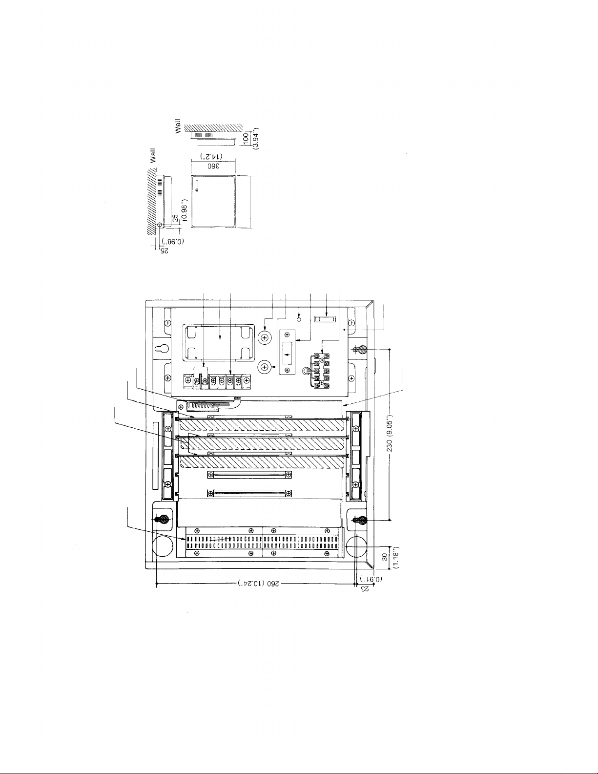
in mm
EX-16 DIMENSIONS
3
n
(a) Structure of Exchange and Names of Parts
Connector
Central Processing Unit (CPU-16)
Line Amp Unit (LAU-16)
Terminal for Station
Short Bar
Power Transformer
Terminal
AC Fuse Holder
DC Fuse Holder
Power Indicator
Voltage Selector
Power Switch
AC/DC Input Terminal
— Power Supply Module (DSM-16)
Mother Board
Page 6
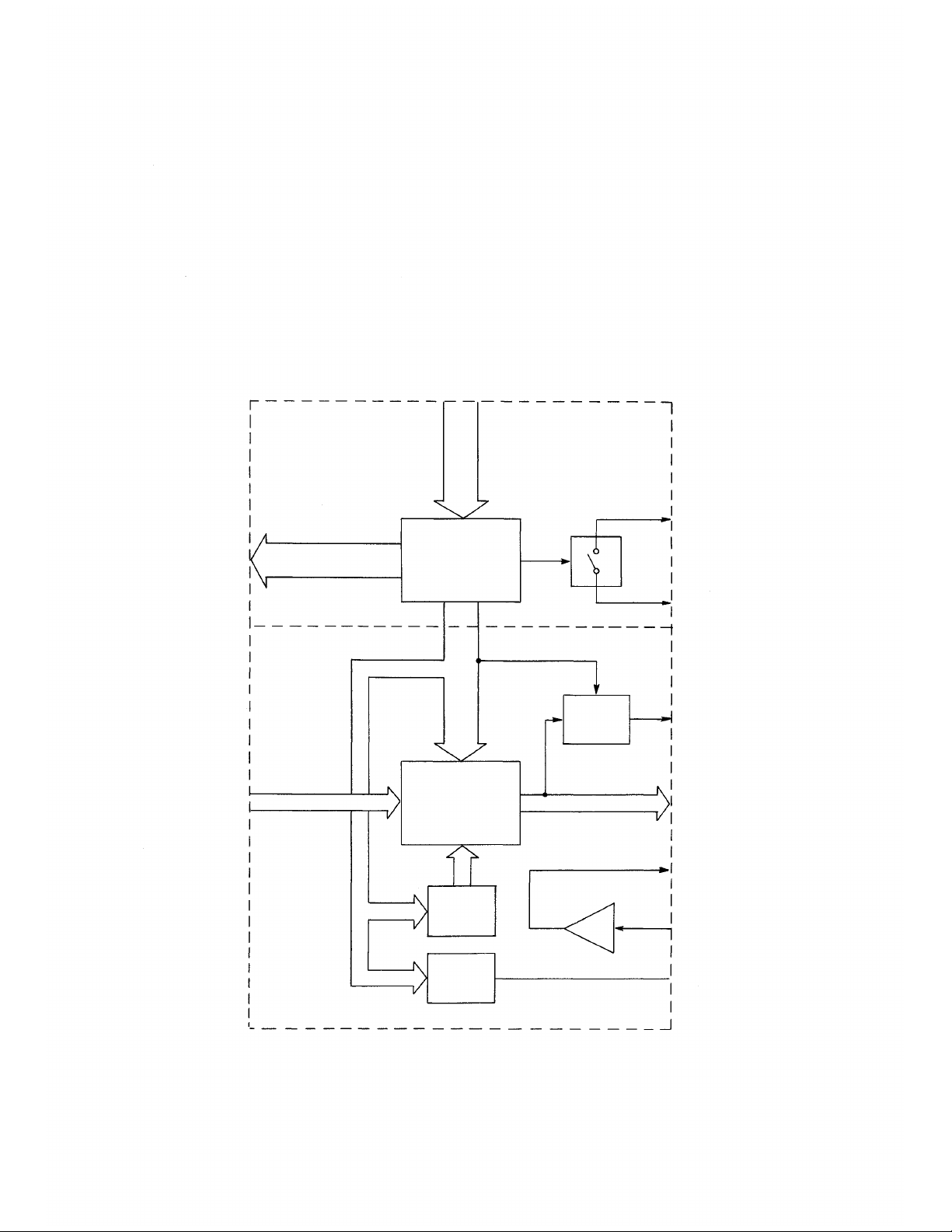
(b) CPU (Central Processing Unit)
The Central Processing Unit is divided into two sections: common control
and speech path.
Common control: This section consists of a microcomputer and associated
other circuits. It controls receiving dial data from stations, opening and
closing of speech path, controlling of signal, paging and BGM switches in
accordance with the exchange program.
Speech path: This section consists of a voice switching circuit, signal
generator, link busy signal circuit, BGM amp and the paging amp. It is
controlled by the common control section.
dial
data
input
control output
speech signal in
common
control
circuit
link
control
link
(voice switching
circuit)
signal
generator
link busy
remote
control
paging
speech signal out
BGM
4
Page 7
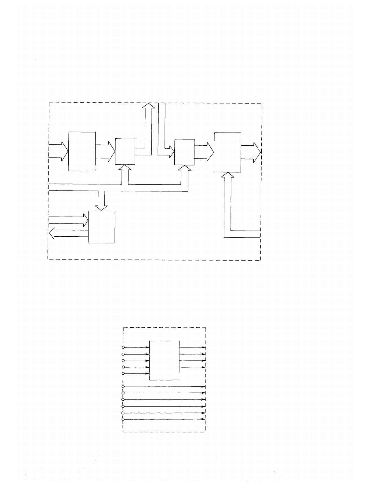
(c) LAU (Line Amplifier Unit)
The Line Amplifier Unit consists of a power supply circuit for stations,
transmitting and receiving circuits for voice signal, speech path switches,
BGM switches and the dial data receiving circuits.
One unit accepts up to 4 stations. A maximum of 4 LAU's can be installed.
receiving
circuit
control signal
dial data in
out
dial
receiver
switch
T
switch
R
transmitting
circuit
BGM/AII
call/Link
busy
(d) DSM (Power Supply Module)
The Power Supply Module consists of a power supply unit for the exchange
and terminals for external input and output connections. This module is
attached to the mother board with a connector and can be easily detached
from the exchange.
AC in
GND
DC in
remote
BGM in
paging out
power
supply
circuit
5V
18V
24V
GND
5
Page 8
(e) Integral Terminal for Connecting Stations
The connection terminal for the exchange and stations is built into the
exchange and connected to each LAU with a mother board.
(Wiring of the terminal and the station will be explained in a separate
section.)
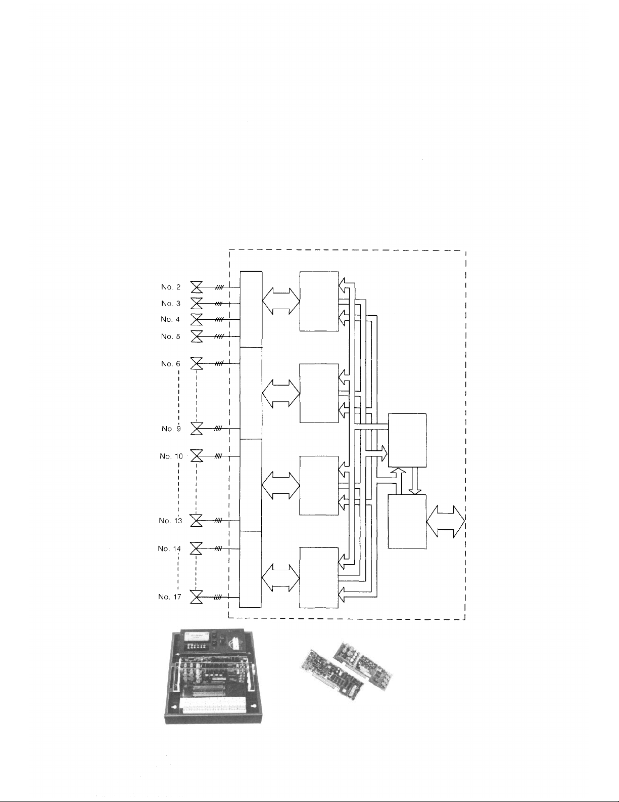
2.1.4 System Block Diagram
A block diagram of the EX-16 system is shown below. In a standard system,
at least one LAU-16 is installed. The remaining units are optional.
Each LAU-16 contains the necessary circuitry for four stations.
Station
Terminal
LAU-16
(1)
LAU-16
(2)
CPU-16
LAU-16
(3)
DSM-16
LAU-16
(4)
Inside View
Units
6
Page 9
2.2 Stations
2.2.1 Features
The stations used in the Toa Intercom EX-16 have the following features:
1. Each station is provided with a male 4-pin plug (YC-102) for easy con-
nection to cables.
2. Wiring from the exchange to each station is an independent 4-wire
system. The fact that only 4 wires are necessary makes installation
easier, and with a 4-pin jack (YC-101 or YC-103) at the end of each
cable, connection can be made quickly with only a screwdriver.
There are three types of stations available: the desk-top type, the
flush-mounting type and the desk/wall type. Each type is available in 2
models (master and substation) and can be chosen in accordance with
requirements.
2.2.2 Specifications
Stations are available in the following three models.
Model
Function
Master Station
Type
Substation
Optional Accessories:
Master Station:
Sub Station:
Desk
Type
with
Handset
HFM-500
HFS-500
YC-100 Wall mounting panel for HFM-100 and
HFS-100.
YC-510 Back box for HFM-510 and HFS-510.
Flush Mount
Type
with
Handset
HFM-510
HFS-510
Desk/Wall
Type
without
Handset
HFM-100
HFS-100
Capable of calling any master/substation in
the system, and also of using all available
functions.
Capable of calling only its Master Station, and
also of using the privacy, single digit dialing
press-to-talk and BGM selection functions.
7
Page 10
Station Specifications
Permissible Loop
Resistance:
Input/Output Impedance:
Loudspeaker Output:
Handset Speaker Output:
300 ohms
600 ohms (balanced)
300mW maximum
100mW maximum
2.3. Accessories
2.3.1 Wall Mounting Panel (YC-100)
The wall mounting panel is used for HFM-100 and HFS-100 when these
stations are to be surface wall-mounted.
2.3.2 Talk-Back Unit (TKU-11)
This unit, optional amplifier (10W max.) and speaker (Hi-Z) will allow high-
volume paging with response from speaker. Conversations are conducted
by using the press-to-talk bar for press-to-talk and release-listen. The
talk-back speaker also operates when all-call paging is made from a master
station.
TALK-BACK UNIT
MAX 10W
SPEAKER Hi-Z
Fig. 5
8
Page 11
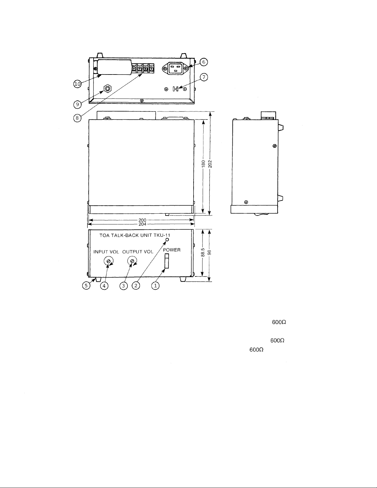
1. Power Switch
2. Power Indicator
3. Output Volume Control
4. Input Volume Control
5. Rubber Foot
6. AC Inlet
7. Voltage Selector
8. 8-Pin Terminal Board
9. Output Jack
10. Terminal Board Cover
SPECIFICATIONS
Power Source:
Input:
Output:
Control:
Speech Control:
S/N
Dimensions:
Weight:
100~120/200~240V AC
Talk-Back Max. 30 dBm,
Amplifier Max. 10W, Hi-Z
Talk-Back Max. 10dBm,
Amplifier 0dBm,
Voice Switching
Voice Switch or Press-To-Talk
55dB
204 X 202 X 98mm
2kg
9
Page 12

3. Installation of the EX-16 System
3.1 Precautions for Installation
3.1.1 Exchange
Pay particular attention to the following points:
* The layout should allow easy servicing and inspection.
* The exchange is compact and lightweight; however, it is important to
ascertain the strength of the wall on which it will be placed.
* The exchange should be grounded. When it is used in combination with
other systems (for example, with a PA system) the exchange should
be connected to the other components for common grounding.
* Choose a low "source noise" AC power supply for the exchange. Line
noise can affect speech quality.
* Make sure that the AC power circuit provides adequate insulation and
capacity.
This high-performance exchange is compact as well as quiet, and can be
easily installed almost anywhere. Areas described below, however, should
be strictly avoided.
* An area where it will obstruct traffic, for example, in a hallway or near
the entrance or exit of a room.
* An area where it will be exposed to fire, heat or direct sunlight. Suitable
ambient temperature is +32°~104°F (0°~40°C).
* A dusty area where it will be exposed to metal dust or dirt.
* Near a storage place for chemicals, oil, etc.
* An area subject to vibration.
* Near high-voltage equipment.
* In a strong electrical field.
* Near equipment vulnerable to the influence of an electrical field.
10
Page 13

3.1.2 Stations
Particular attention should be given to the following points during
installation.
* A desk-type, wall-mounting-type or desk/wall-type should be chosen
according to the user's need.
* If the all-call paging or talk-back function is adopted, precautions should
be taken to ensure against feedback due to interference between the
station (microphone) and the paging or talk-back speaker; that is, they
should be installed facing different directions or separated as far as
possible from each other.
* The "para-branching" operation or the connection of more than one
station to one circuit is not possible.
* Adjust the volume switch and volume control on the station for com-
fortable speaker output level or for avoiding troublesome acoustical
conditions (e.g., reverberation or echo).
Stations are compact for easy installation almost anywhere. However, areas
described below should be strictly avoided.
* An area where it will be exposed to fire, heat or direct sunlight.
* A dusty area where it will be exposed to metal dust or dirt.
* Near a storage place for chemicals, oil, etc.
* An area subject to vibration.
* Near high-voltage equipment.
* In a strong electric field.
* On the same circuit as a SCR type light dimmer.
3.1.3 TKU-11
The talk-back unit is to be installed with an optional amplifier (10W max.)
in the place where the talk-back function is desired.
The speaker is to be a Hi-Z trumpet speaker installed on the ceiling or wall.
The optimum installation site for the speaker is approximately 2m from
speaking position. The talk-back unit should be placed by the optional
amplifier. The speaker should be installed as close to the talk-back unit
as possible.
Be sure to use shielded cable or twisted cable for the speaker wires to
prevent interference caused by high-voltage cables, electromagnetic
induction and high-frequency waves.
11
Page 14

3.2 Cable Installation
Wire type, number of wire pairs and number of individual wires are to be
determined for individual sections of the wiring system according to the
guidelines set down below.
* 4-wire twisted pair cables are to be used for wiring between indoor
terminal boards, intermediate terminal boards, main terminal boards, etc.
* Outdoor wires should be used where wiring passes through inaccessible
areas such as in ceilings or under floors. Indoor wires may also be used,
however, in cases where there is no risk of deterioration due to exposure
to heat, etc.
* The number of cable pairs laid should be determined considering the
possibility of future expansion of the system.
* There is a limit to the diameter of cables that can be used to connect
stations to the terminals of EX-16. This limit must be taken into con-
sideration when planning the wiring of this system. The diameter should
measure between 0.016" (0.41mm) and 0.031" (0.79mm).
3.3 Core Diameter Versus Transmission Distance
The diameter of the cable to be used should be determined so that the set
limits for speech attenuation (3dB maximum for transmission from the
exchange to the station) and for the DC resistance (DC loop resistance: less
than 300 ohms) are met.
AWG no.
(solid)
22
24
Speech Attenuation, DC Loop Resistance and Service
Distance as Functions of Core Diameter
Core
Diameter
mils. (mm)
25.3
(0.64)
20.1
(0.51)
Speech
Attenuation
dB per 1000 ft.
(dB per 1 km)
0.411
(1.35)
0.521
(1.71)
DC Loop
Resistance
per
1000
per 1 km)
35.1
(115)
54.5
(179)
ft.
Service
Distance
ft.
(km)
7,300
(2.2)
5,500
(1.1)
12
Page 15

3.4 Wiring
General Information
* Wiring should be done independent of public telephone lines.
* The wiring conduit is often installed underground or embedded in
building structures such as walls and floors, so care should be taken
to draw up a wiring plan that has ample reserve for future extension of
the system and that can be adapted to future remodelling or expansion
of the building it is housed in. Wiring systems must be planned with
ample wires, a conduit and with provisions for additions to the system.
Spacing
Since the working voltage of this system is low and the current passing
through it is small, there is no major safety problem involved in the wiring.
However, since interference due to contact with other indoor wiring can
cause wire damage, leakage and other problems, spacing should be given
close consideration when the small-current wiring of this system is laid
close to other indoor wiring, particularly AC wiring.
The following chart lists spacing standards to be followed in respect to
typical causes of interference.
Cause of Interference
Heating pipe
Water pipe
Radio transmitting coaxial
cables (CB and other).
Telephone wire.
Radio/TV antenna coaxial
cables & twin lead.
Ground cable.
Protected heating and
cooling pipes
Minimum
spacing
acceptable
without extra
protection
6" (15 cm)
4" (10 cm)
12" (30 cm)
4" (10 cm)
Remarks
This minimum spacing
requirement should be
observed, since intercom
cable is vulnerable to heat.
More spacing is required
where there is a risk of
induction.
13
Page 16
3.5 Piping
* Where wiring is to be passed through a wall or the like, it should be
protected by a hard PVC or metal tube.
* If the number of connecting wires between an indoor terminal board
and a station is small and the station's site is fixed so that it will not be
moved frequently, install a box at that site and pull wiring through a
metal or hard PVC tube as required by job or ordinance.
* Use a floor duct if the number of connecting wires is large and the
stations are likely to be moved frequently.
* Station wiring which must be laid across open areas of floor should be
protected by plastic or metal shields. (See drawing below.)
EXAMPLE:
Wall
Box
Floor duct
Metal or Hard PVC tube
Wire protector
4-Pin Jack
& Plug
Wire protector
Floor
Plastic or
Aluminum
Desk
Station wiring
Floor
Fig. 10
14
Page 17
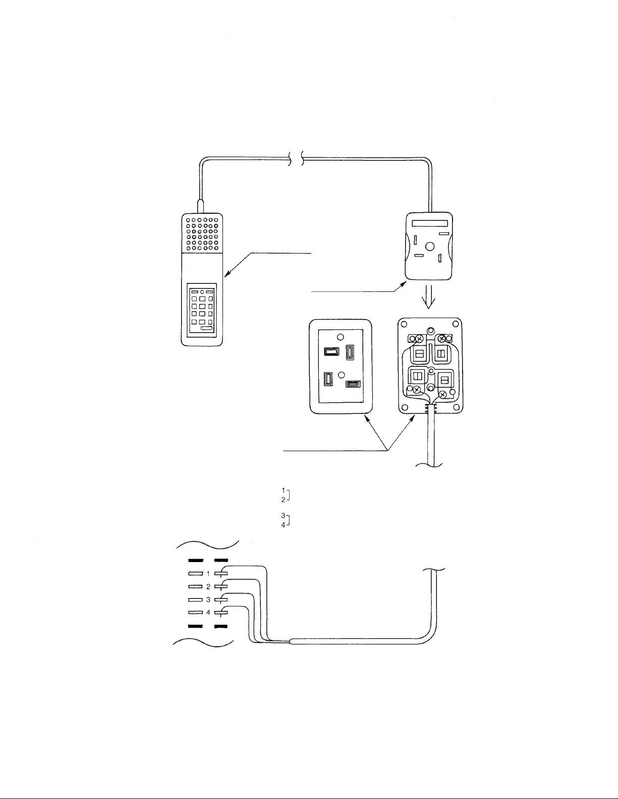
3.6 Connection between the station and the exchange
Station
4-Pin Plug (YC-102)
(Cover)
4-Pin Jack (YC-101)
(YC-103: 4-Pin Jack for flush-mount)
NOTE: Use 4" X 2" Switch Box for YC-103.
Receiving Lines
(not Polarity Specified)
Transmitting Lines
(not Polarity Specified)
(Viewed from the station side)
Plug in
15
Page 18
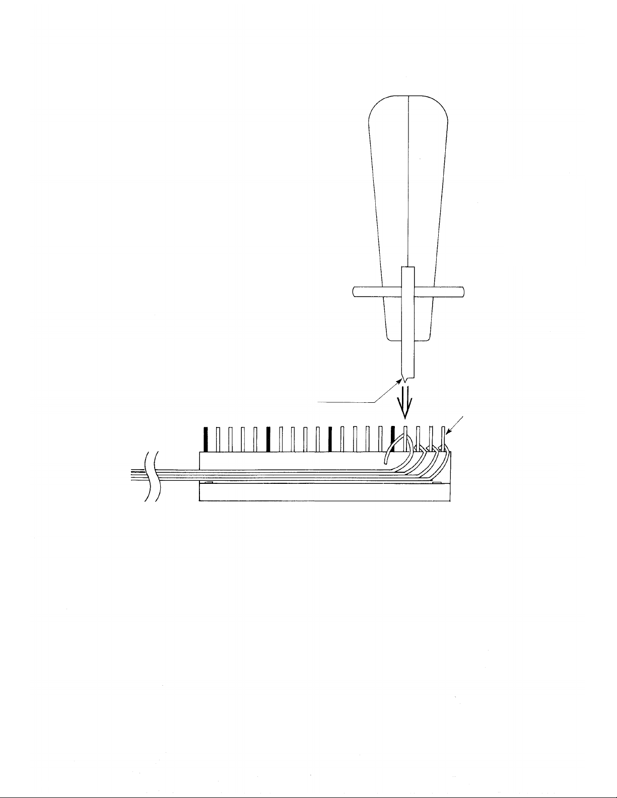
Note:
Connect the individual cables in
order, starting with the top ter-
minal.
When using the clipping tool, be
sure that the cutting edge is on the
side of the wire to be cut off.
Clipping Tool C (YC-105)
Cutting edge
Clip Terminal (Side View)
Push down
Clip Terminal
16
Page 19

TERMINAL BOARD
EX-16 WIRING INSTRUCTIONS
1 STATION CONNECTIONS
or
2 TALK-BACK CONNECTIONS
TKU-11 TERMINAL
SPEAKER LINE INPUT
17
Page 20
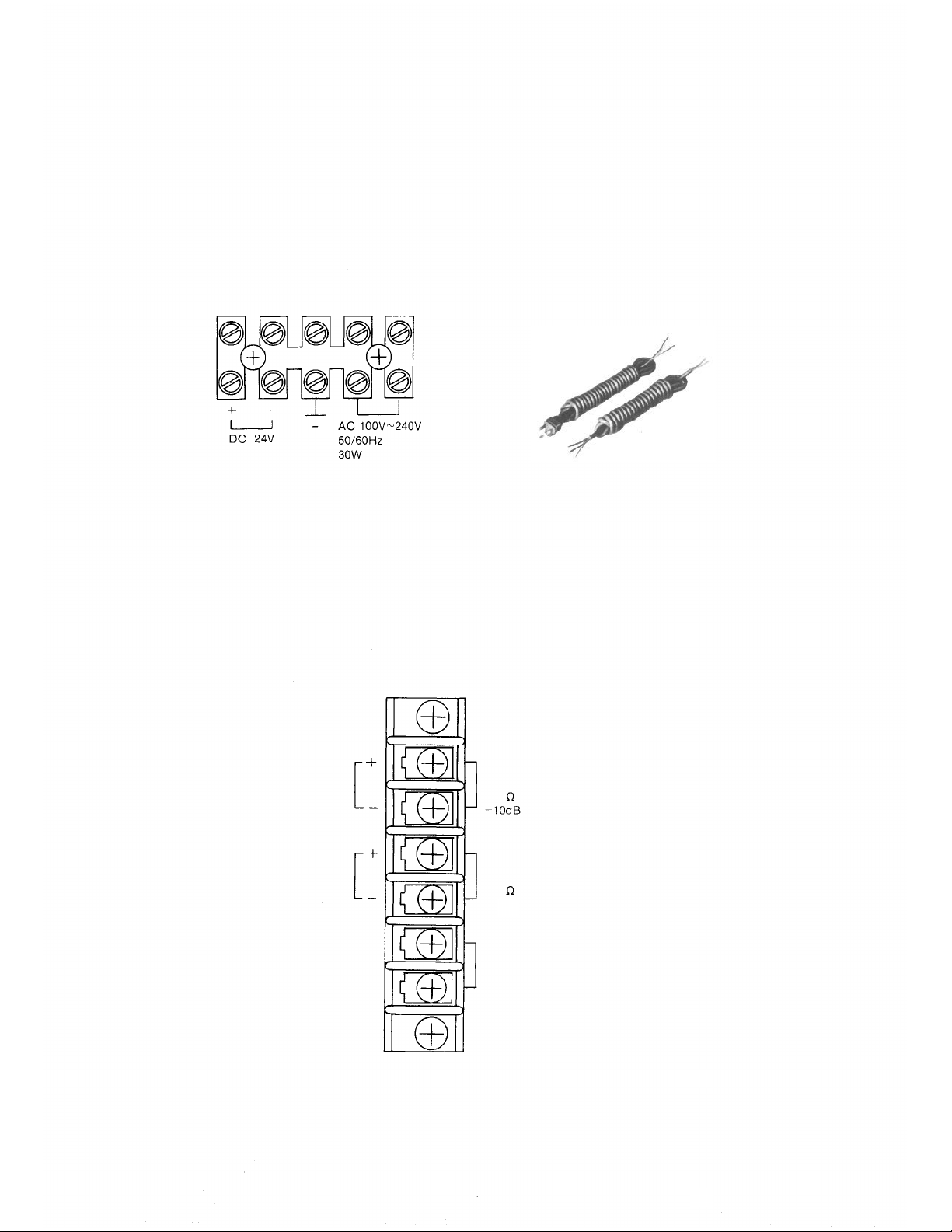
3.7 AC/DC Power Supply Connection
A 5P terminal for AC and DC power supply is provided on the DSM-16.
The power cable, YA-308 or YA-309, can be connected to the 5P terminal.
Be sure to ground the exchange.
5P Terminal on DSM-16
Power Supply Cables
YA-308
YA-309
3.8 Connection of the Input/Output Terminal
A 6P terminal for the input/output signals of the EX-16 is provided on the
DSM-16.
6P Terminal (DSM-16)
18
BGM IN
UNBAL
50K
PAGING OUT
UNBAL
600
0dB
REMOTE OUT
MAX 125 VA
Page 21

3.8.1 BGM Input
Input impedance: 50 K (unbalanced)
Input level: -10dB max.
Output level: 100mW
(a) Remove the short bar connected to the terminal.
(When BGM is not employed, the short bar should be kept on the terminal.
If the short bar is not replaced, a humming sound will be heard from the
station.) The short bar is referred to on page 3.
(b) Connect the BGM equipment. (Be sure to use the type of BGM equipment
which meets the input specifications. Since the level adjustment cannot be
controlled in the exchange, the BGM equipment must have an output
level adjuster.)
(c) After installation, adjust the output level of the BGM through the speaker.
If the input is excessive, there will be distortion.
3.8.2 All-Call Paging Output
Output impedance: 600 (unbalanced)
Output level: 0dBm
(a) Connect a paging amp which matches the output specifications.
(b) Test the paging output level and adjust to eliminate feedback. (Placing the
speaker too close to the station sometimes causes feedback.)
3.8.3 Remote Control Output
Output signal: no voltage contact
Contact capacity: 125VA
The program switch on the CPU-16 allows selection of either of the
following 2 functions for remote control.
1. Door Remote Control
Every master station can be used as a remote control device for the door
opening function. Pressing buttons
wherein the door can be opened.
2. Power On/Off Remote Control
and
allows a 4-second interval
When the system is used in conjunction with a PA amplifier for the
external all-call function, the power switch of the PA amplifier can be
turned on/off with the relay built into the system. Pressing buttons
invokes the make-contact and the all-call function until it is cancelled
by pressing
and
19
Page 22

3.8.4 Wiring Diagram
BGM
AMP
DOOR
20
Page 23

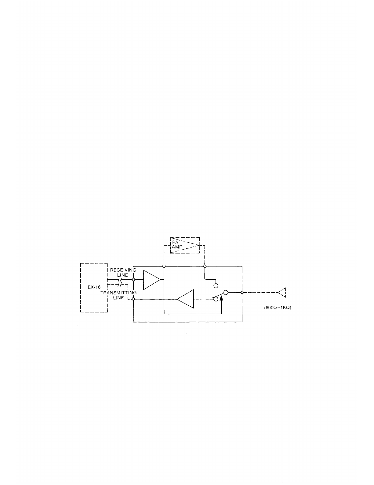
3.9 Connection of the Talk-Back Unit
Connection of the talk-back unit is shown below.
SPEAKER
EX-16
TERMINAL
BOARD
SPEAKER
TKU-11
Fig.
14
When the talk-back speaker is used as a microphone, sound clearness and
microphone sensitivity vary according to the ambient noise level and in-
stallation position. The sensitivity of the talk-back speaker's microphone
can be adjusted by the input volume control on the front of the TKU-11.
Adjustment is necessary after installation.
21
Page 24

3.10 Connection of the Speaker Station
In the EX-16, instead of using a station, a speaker for one-way conversation
can be installed using a jumper in the LAU-16.
This is possible at each station position on the LAU-16.
3.10.1 Wiring Procedure
(a) First, determine the number of station speakers to be installed. (Any number
of station speakers may be connected within the limits of the station
numbers from No. 2 to No. 17.)
(b) Use the Wiring Instruction Chart to determine the LAU No. and Jumper No.
corresponding to the station number. (See page 24.)
(c) Remove the corresponding LAU-16 from the mother board.
(d) Connect the corresponding jumper points with the jumper wire. (See page
24.)
3.10.2 Speaker Volume Adjustment
1. Speakers with an impedance of 600 ohms or more may be used without
the need for a transformer.
If it is desired to use lower impedance speakers, a transformer should be
used to assure proper impedance matching.
2. Volume may be controlled only when:
(a) a matching transformer is used.
To exchange
(b) a resistor is connected.
To exchange
The Rs value should be decided in accordance with the speaker impedance
so that the volume is on a suitable level.
22
Page 25

3.10.3 Connection with the Exchange
Connect speakers to terminals 1 and 2 as shown in the diagram. (Leave
terminals 3 and 4 open.)
3.10.4 On/Off Control of BGM
BGM can be turned off when the jumpers are connected as shown in the
diagram. If the jumpers are not connected, BGM will be heard from the
speaker stations constantly. (See page 24.)
23
Page 26

Jumper for Speaker Station Selection
Jumper for BGM On/Off
For BGM on/off operation remotely, the
control line can be extended the same way
as for station wiring.
24
How to Connect the Jumper Wire
1. Use a 0.6mm diameter plated wire as jumper.
2. Solder on the soldered end.
3. Use a so ldering iron with less than 30W power
and with minimum leakage.
Be careful not to touch other parts.
Page 27
4. Installation Adjustment
4.1 Inspect Before Turning Power On.
* Before supply power, check the power connections (power connections
should be complete) and the fuse. Also, voltage selector should be set
correctly. All modules should be in place.
Check the ROM on the CPU-16. It should be set securely in the socket.
Make sure that exchange and stations are properly connected.
* Turn power on.
* AC indicator lamp on the DSM-16 should go on. If not, electricity is not
on. Turn off power and check the connections and fuses.
* Handle plug-in units with care; plug-in units incorporate CMOS. After the
exchange is turned on, do not attempt to disconnect the plug-in units.
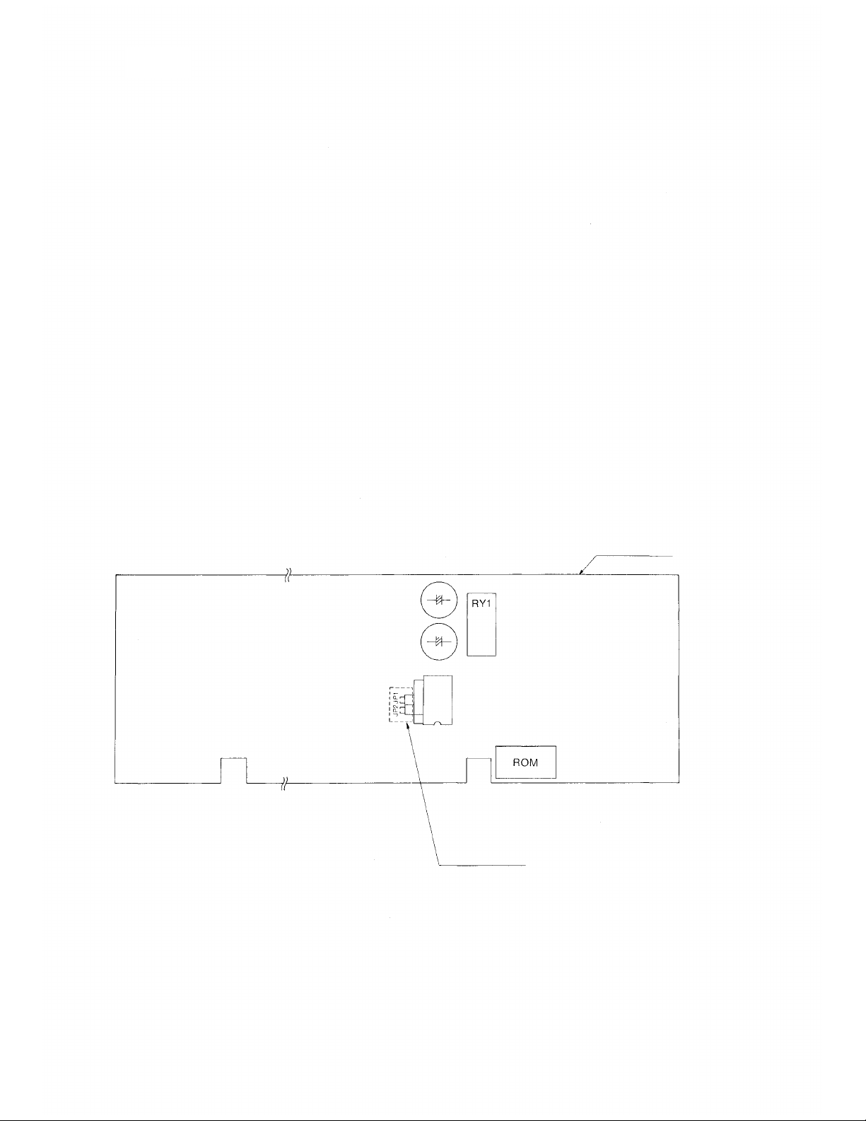
4.2 Function Selection
Select door remote or power remote, as shown in the following diagram,
using the program switch on the CPU-16.
Program Switch
CPU-16 P.C.B.
25
Page 28

Program Switch Details
Power Remote
Door Remote
1. Set the mini-jump in the JP1 position for door remote. Relay goes on for
4 seconds when buttons and are pressed.
2. Set the mini-jump in the JP2 position for power remote.
Press
buttons and to turn relay on.
Press button to turn relay off.
Note: The unit is set in the JP1 position (door remote) at the factory.
4.3 Testing
After: 1. wiring is completed
2. power is turned on and all system functions are checked,
then, testing for adjustment should be carried out. The plug for each station
should not be connected until the speech test is started.
26
Page 29
4.3.1 Precedure
(1) Turn on power switch on the exchange.
(2) Adjust the sound level of the external PA paging and check the power
remote function.
(a) Connect one station.
(b) Press buttons and to test the sound level. Adjust the volume
control of the external amplifier.
(3) Complete a speech test with each of the other stations.
(a) Connect the plug for the station to be tested.
(b) Dial the station number. Check the sound level and the speech quality.
(c) Dial and . If a howling noise is heard, then the paging or speaker
stations are too close together.
(4) After the speech test is completed for all stations, the sound level adjust-
ment for BGM should be done. To begin, the sound level should be set
so that the BGM is heard from all stations when the power switch of the
exchange is turned on. To turn off the BGM, press the key once.
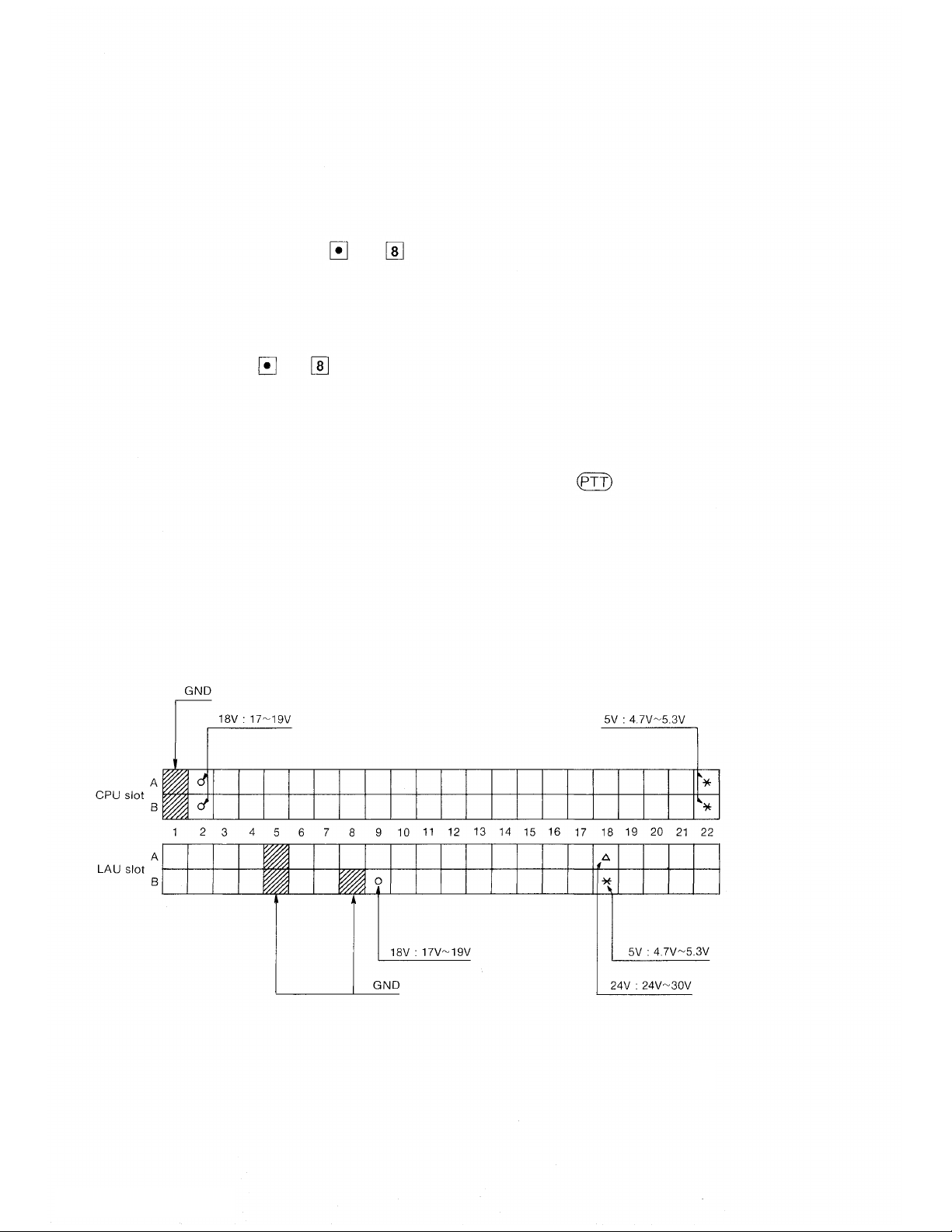
4.3.2 Adjusting Method
(a) If exchange does not work:
(1) Turn off the power and disconnect all units from the mother board.
(2) Turn on the power and check the DC voltage at the points on the
mother board illustrated below.
27
Page 30

(3) If the voltage measured is normal at every point, connect one unit
at a time checking the voltage after each connection.
(4) If the voltage is upset after connecting any given unit, the unit is to
be replaced.
(b) If there is no response to dialing:
(1) Disconnect the plug for the particular station from the line and
check the wiring between the exchange and the station.
(2) If no wiring error is detected, test after changing each station.
(3) If preceding steps do not remedy the situation, replace the units
attached to the station in the same order as the LAU-16 and CPU-16
and test again.
(c) In the event of a conversation failure or persistent noise during
conversation,
(1) Disconnect the plug between each station and the exchange and
check the wiring.
(d) If conversation is frequently interrupted:
(1) If speech from A to B is interrupted, turn down the volume control
of speaker at B's station.
(2) If speech from B to A is interrupted, turn down the volume of
speaker at A's station.
(3) If conversation is interrupted both ways or block oscillation
should occur upon ceasing of the ringing tone, turn down the
volume at both stations.
Note 1: The volume control is located at the back of the station. Adjust with
a small (—) screwdriver.
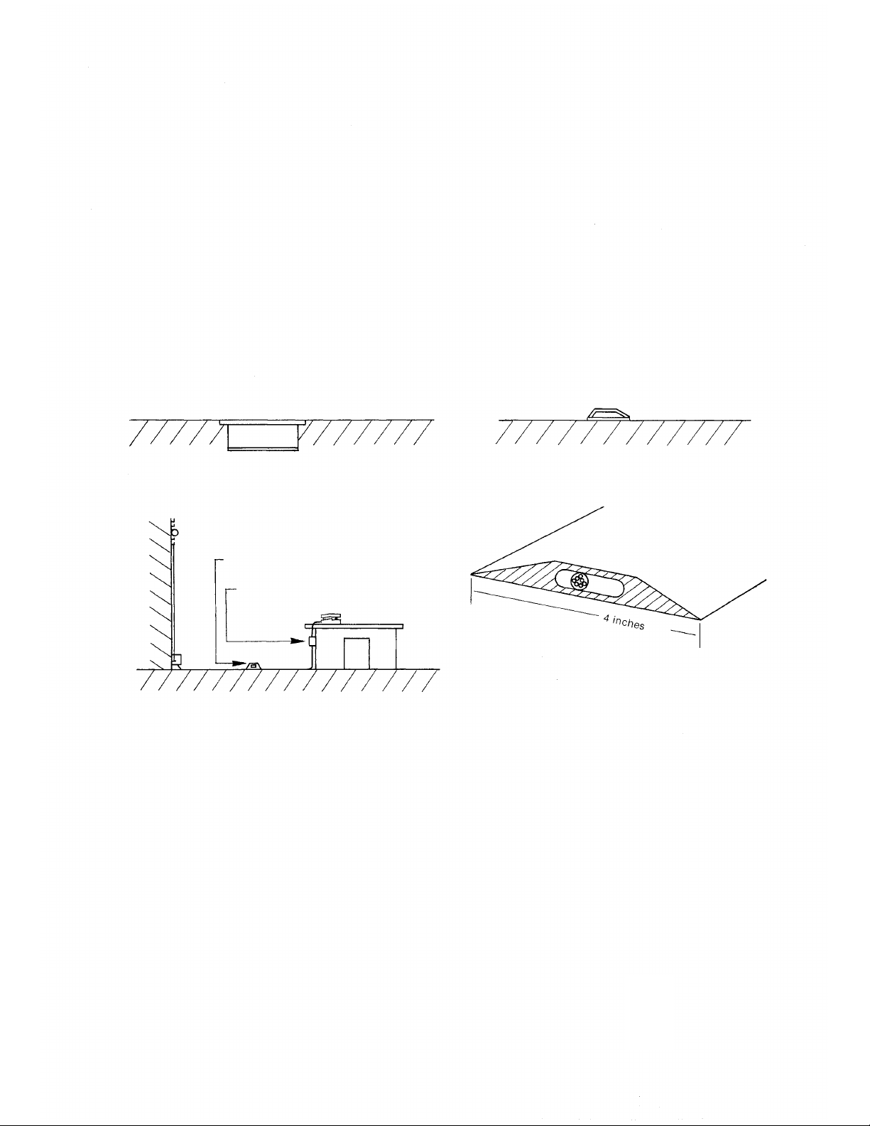
Note 2: The above-mentioned trouble tends to occur when the station is
installed in a room subject to echo or reverberations or when the
station is not located properly with respect to the walls of the room it
is in. Avoid installation of the station in any of the locations illus-
trated in the following diagram.
28
Page 31
4.3.3 Relationship Between Ambient Noise and Conversation Mode
The EX-16 system is provided with voice switches for the press-to-talk
function which is required when the ambient noise level is high. Below is
a guide for using the press-to-talk function.
(Up to 60 phons)
(A)
(Up to 60 phons)
(A)
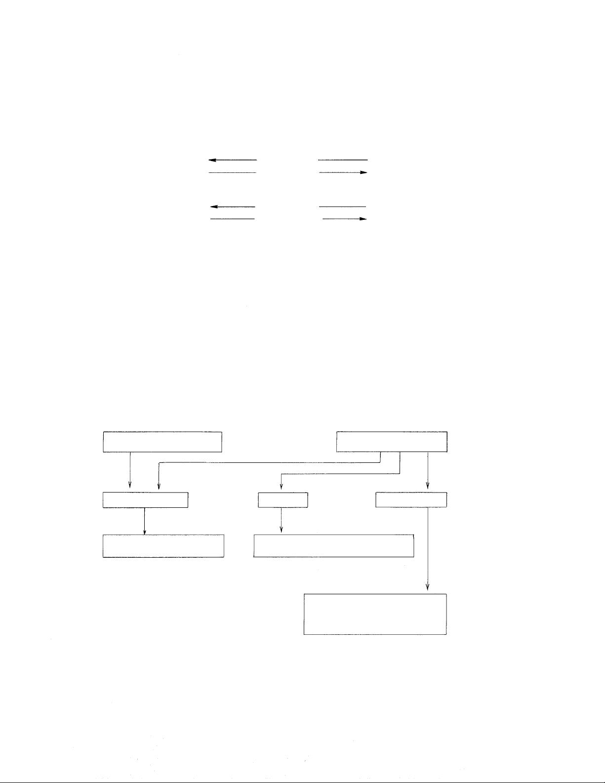
5. Trouble Shooting Guide
Repairing of the EX-16 system is basically done by replacing defective
units with good ones. The system's faults in an installation can be divided
into the following categories.
1. Faults in an exchange
2. Faults in a station
3. Faults in cable
To make system repairing easier, find which category is involved, then
refer to the chart below for assistance in fault-finding.
All stations do not operate.
Same symptom in every station.
(Hands free)
(Hands free)
(Hands free)
(Press-to-talk)
(Up to 60 phons)
(B)
(Above 60 phons)
(B)
Fault in specific station only.
Fault in an exchange.
* Power supply
* Plug-in unit (Common control)
Cable fault.
* Mis-wiring such a short, broken wire, etc.
* Misconnection in station jack.
* Key board switch fault.
* Board assembling fault.
* Speaker, microphone fault.
* Microswitch, connecting cable fault.
Fault in a station.
29
Page 32

5.1 Fault in Exchange
* When the power supply unit or the CPU-16 is out of order, the same kind
of fault will occur at all stations.
* When the LAU-16 is out of order, a fault will appear only at a particular
station.
* If the exchange is out of order, the faulty unit must be searched out and
replaced.
Fault in exchange
Check the power unit
(See 4.3.2)
Yes
Replace CPU-16
No
Replace LAU-16
End
Yes
No
Fault
Replace DSM-16
Yes
30
Page 33

5.2 Fault in Specific Station Only
Find the cause according to the following table if the fault lies with a specific
station only, not with all stations.
SYMPTOM
Dialing can not be
made at privacy off
mode.
Specific key does not
operate.
Calling tone can
not be heard.
Sound fro m the
other party can not
be heard.
Sound is not trans-
mitted to the other
party.
On dialing, noise is
heard by the called
party.
CHECK-ITEM
Replace the
station and make
sure that the
station is not
faulty.
Replace the
station and make
sure that the
station is not
faulty.
Same symptom
remains even if
the station is
replaced.
Becomes normal
if the station is
replaced.
Same symptom
remains even if
the station is
replaced.
Becomes normal
if the station is
replaced.
Same symptom
remains even if
the station is
replaced.
Becomes normal
if the station is
replaced.
CAUSE
* Disconnection of both T & R Lines.
* T & R Lines are shorted.
* Fault in key board switch or matrix circuitry.
* Fault in the dial generator. (Replace PCB
board.)
* Short or open in R Line.
* Fault in LAU.
* Disconnection of R Line or improper connec-
tion of the station connector.
* Fault in LAU.
* Station fault.
* Short or open in T Line.
* Fault in LAU.
* Fault in MIC circuitry of the station. (Replace
MIC or
PCB.)
* One of T Lines is disconnected.
* Fault in LAU.
* Fault in MIC element.
* Fault in T Line of the station.
* Low-frequency oscillation of MIC AMP.
(Faulty bypass capacitor.)
Sound of the other
party is broken during
call.
Immediately after the
calling tone, the line
switches to cancel,
busy, dial tone, etc.
Same symptom
remains even if
the station is
replaced.
Same symptom
remains even if
the station is
replaced.
Becomes normal
if the station is
replaced.
* Adjust the volume control of station speaker
if the room produces reverberation. (Lower
the volume.)
* Increase the gain of MIC AMP.
* Replace PCB after checking if MIC unit is not
touching its case.
* One of R Lines is disconnected.
* Fault in LAU.
* Station fault.
* One of the R Lines is disconnected or the
station connector is not connected properly.
31
Page 34
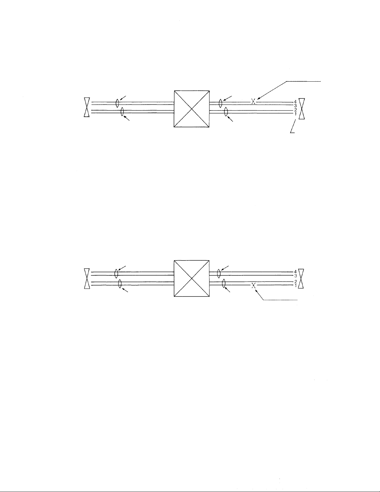
5.3 Fault in Cable
1. One of transmitting lines (T-Line) is disconnected
Disconnected
Station (B)
Symptom:
T-Line
R-Line
EXCHANGE
1-1 A can dial.
1-2 A can hear B.
1-3 B can not hear A.
1-4 Noise is heard at B.
1-5 Noise increases at B when Press-To-Talk
bar is pressed at A.
2. One of receiving lines (R-Line) is disconnected.
(B)
T-Line
T-Line
R-Line
T-Line
Station (A)
Connector
numbers
(A)
Symptom:
R-Line
R-Line
EXCHANGE
Disconnected
2-1 A can dial without dialing tone.
2-2 When B dials A, busy tone or dial tone
will be heard at B immediately after the
calling tone.
32
Page 35
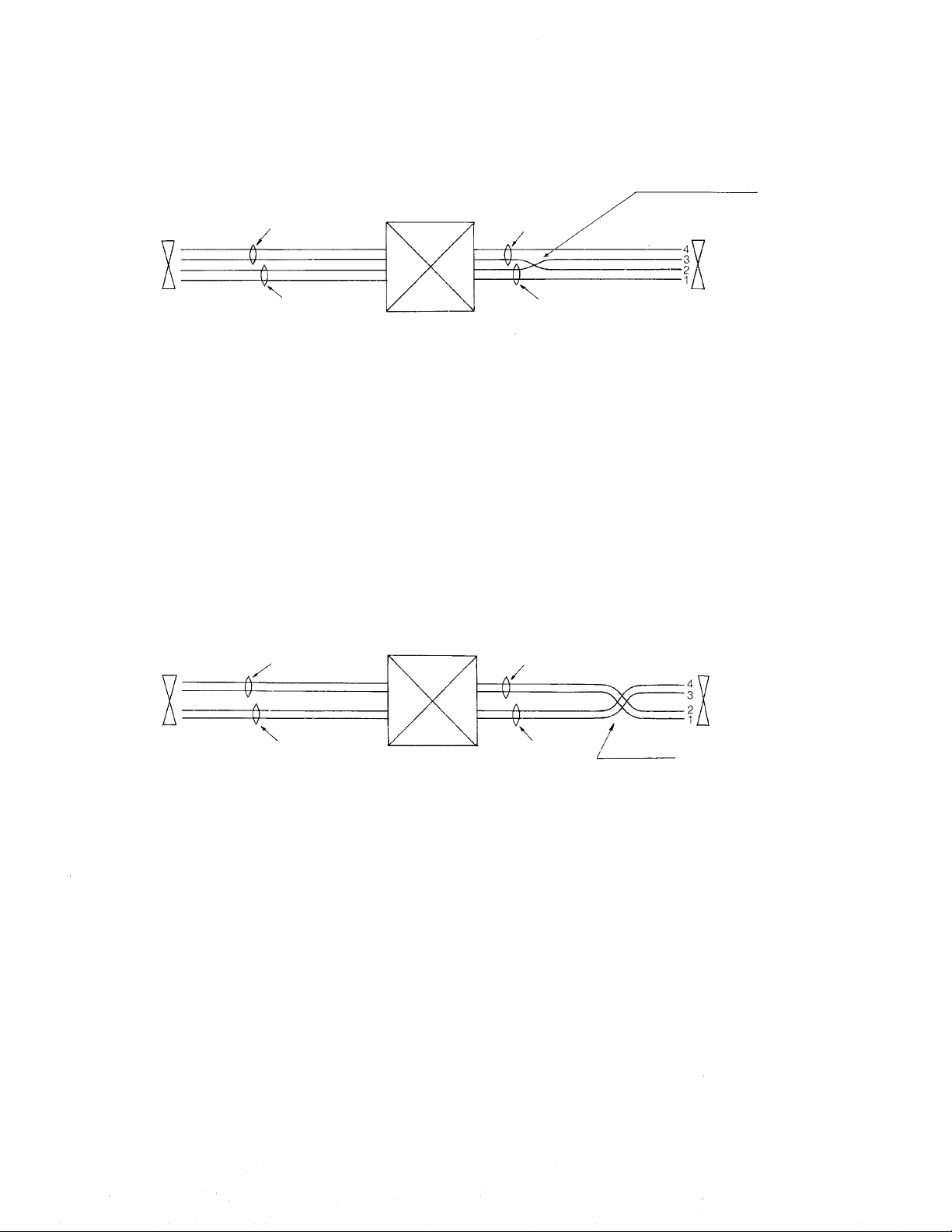
3. T-Line and R-Line are shorted or mixed up.
Shorted or mixed up
(B)
Symptom:
T-Line
R-Line
EXCHANGE
3-1 A can not dial.
3-2 Conversation is impossible between
stations.
3-3 When B dials A, noise will be heard at
B immediately after the calling tone.
4. T-Line and R-Line are connected conversely.
(B)
T-Line
T-Line
R-Line
T-Line
(A)
(A)
Symptom:
R-Line
EXCHANGE
R-Line
Conversed
4-1 A can not dial.
4-2 Conversation is impossible between
stations.
4-3 When B dials A, noise will be heard at B.
33
Page 36

TOA ELECTRIC CO., LTD.
KOBE, JAPAN
Printed in Japan
 Loading...