

Page 1
Copyright © 2011, Tjernlund Products, Inc. All rights reserved P/N 8504174
OWNER INSTRUCTIONS, DO NOT DESTROY
Recognize this symbol as an indication of important Safety Information!
THESE INSTRUCTIONS ARE INTENDED AS AN AID TO QUALIFIED, LICENSED
SERVICE PERSONNEL FOR PROPER INSTALLATION, ADJUSTMENT AND
OPERATION OF THIS PRODUCT. READ THESE INSTRUCTIONS THOROUGHLY
BEFORE ATTEMPTING INSTALLATION OR OPERATION. FAILURE TO FOLLOW
THESE INSTRUCTIONS MAY RESULT IN IMPROPER INSTALLATION, ADJUSTMENT, SERVICE OR MAINTENANCE POSSIBLY RESULTING IN FIRE, ELECTRICAL SHOCK, CARBON MONOXIDE POISONING, EXPLOSION, PERSONAL
INJURY OR PROPERTY DAMAGE.
!
DO NOT DESTROY. PLEASE READ CAREFULLY AND
KEEP IN A SAFE PLACE FOR FUTURE REFERENCE.
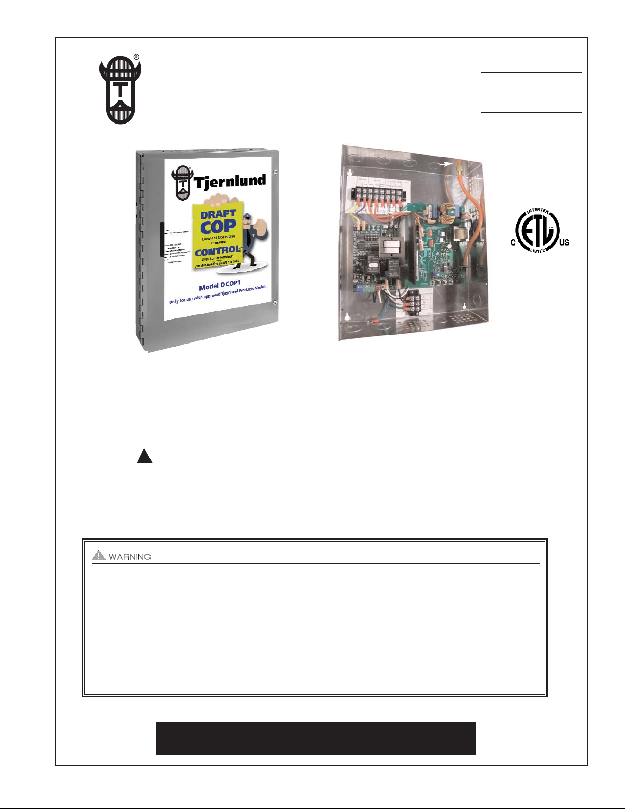
MODEL DCOP1
INSTALLATION INSTRUCTIONS
REV. 3/11
TJERNLUND PRODUCTS, INC.
1601 Ninth Street • White Bear Lake, MN 55110-6794
PHONE (800) 255-4208 • (651) 426-2993 • FAX (651) 426-9547
Visit our web site • www.tjernlund.com
UC1 VERSION
X.06
COP
CONTROL
SENSING
PORT
UC1
CONTROL
INTERIOR VIEW
Page 2

1
TABLE OF CONTENTS
Page (s)
Description and General Information...............................................................................................................................1
Installation Restrictions and Cautions ........................................................................................................................1, 2
UC1 Universal Control Board Features ..........................................................................................................................2
UC1 LED Status / Fault Indicators and Fault Retrieval from Memory.............................................................................3
UC1 Pre / Post-Purge & Pre-Cycle Prover Status Check Settings..............................................................................3, 4
DCOP1 Installation .........................................................................................................................................................4
Sizing a Common Manifold Serving Multiple Heaters ....................................................................................................5
Electrical Wiring
Wiring Connections between DCOP1 and Rooftop Inducer ............................................................................6
UC1 Internal Schematic, Sequence of Operation & Specifications ..............................................................7, 8
UC1 Multiple and Millivolt Appliance interlocks ................................................................................................8
UC1 Wiring to Gas Fired Appliance ............................................................................................................9-11
UC1 Wiring to Oil Fired Equipment ...........................................................................................................11-13
How the Draft COP Works ............................................................................................................................................14
Vent Pipe Sensing Location & PSA-1 Fan Prover Installation.......................................................................................14
Adjusting Draft Set Point & Balancing Heater Draft ......................................................................................................14
Verifying System Operation ..........................................................................................................................................15
Adjustment of Draft Set Point, Balancing Baffles and Barometric Draft Controls .........................................................16
Final Operation and Draft Check...................................................................................................................................16
Troubleshooting, Service and Warranty...................................................................................................................16-19
DESCRIPTION
The DCOP1 combines Tjernlund's standard UC1 interlock control with the (COP) Constant Operating Pressure controller.
It can be interlocked with virtually any burner control circuit. Features include: adjustable pre & post purge, LED status/diagnostic
indicators, 10 second prover switch delay to avoid burner start up and wind induced short cycling. Interlocks with any 24-115 VAC
burner control circuit and also includes "dry" contact actuation option. After each burner cycle the UC1 will continue to operate in
post-purge mode to allow the Inducer to purge the heater and vent of residual flue gases. A pre-purge time is factory set at 5 seconds (adjustable up to 35 seconds) and a post-purge time is factory set at 2 minutes (adjustable up to 16 minutes), see "Pre / Post
Purge Settings" on page 3.
The COP controller measures draft/pressure and modulates the speed of an RT-Series Inducer to maintain a user adjustable
draft/pressure set point. Do not use with any other series of Tjernlund Inducers/Venters. The set point is adjusted through a pot
mounted on the COP circuit board.
GENERAL INFORMATION
Each DCOP1 is electrically factory line tested before shipment.
After opening carton, inspect thoroughly for hidden damage. If any damage is found notify freight carrier and your distributor
immediately and file a concealed damage claim.
INSTALLATION RESTRICTIONS
1. The Pre-Cycle Prover Status Check is deactivated from the factory. When activated, the UC1 Universal Control checks across
P1 & P2 safety circuit (Fan Prover) to verify that the Fan Prover switch is “Open” upon a call for heat and not stuck “Closed”.
Natural draft or winds may be sufficient to close the PSA-1 fan prover switch contacts prior to a call for heat. Keeping the Prover
Status Check activated may cause nuisance lockouts. Push up or “ON” to deactivate. See "P1 & P2 Pre-Cycle Fan Prover
Status Check", page 4 for details.
2. An Inducer post-purge on the UC1 has been factory set at 2 minutes. Confirm that dip switch #5 is in the up or "ON" position. Oil
fired equipment requires that the post-purge be long enough to eliminate post cycle nozzle drip odor. A longer post-purge may
be necessary for longer vent runs or high heat retention, refractory lined combustion chambers. A shorter post-purge may be
desired for gas installations. See "Pre / Post Purge and Prover Status Check Dip Switch Settings", page 3 for details.
3. The DCOP1 is intended for indoor installation only. Do not mount the DCOP1 on a heat source that exceeds 140
O
F (60OC).
Examples of improper mounting surfaces include vent pipe, top of heater casing or any place where radiant or convective heat
would cause the junction box temperature to exceed 140
O
F (60OC).
4. The maximum distance wire can be ran from the RT-Series Inducer junction box to the DCOP1 control is 250 feet.
CAUTIONS
The DCOP1 must be installed by a qualified installer (an individual properly licensed and/or trained) in accordance with all local
codes or, in their absence, in accordance with the appropriate National Fire Protection Association #31, #54, #211 and the
National Electrical Code.
Page 3
2
Failure to install, maintain and/or operate the DCOP1 in accordance with manufacturer's instructions may result in conditions
which can produce bodily injury and property damage.
1. The installer must verify that the BTU/hr. input of the appliance(s) does not exceed the recommended input of the RT-Series
Inducer being controlled by the DCOP1. Refer to the RT-Series brochure or installation instructions for capacities.
2. Disconnect power supply from the DCOP1 and heating equipment when making wiring connections and servicing the DCOP1.
Failure to do so may result in personal injury and/or equipment damage. LED #6 (RED) on UC1 should be off with power removed.
3. All installation restrictions and instructions in the RT-Series Inducer installation instructions must be followed when using the
DCOP1.
4. Make certain power source is adequate for the DCOP1 and Inducer requirements. Do not add equipment to a circuit when the
total electrical load is unknown.
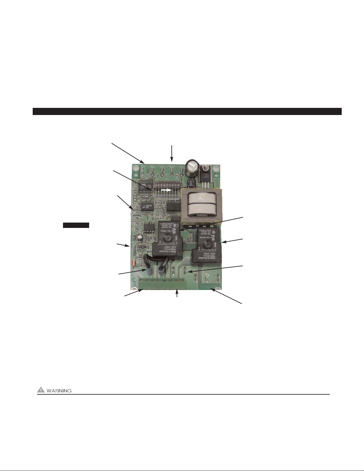
UC1 UNIVERSAL CONTROL BOARD FEATURES
# 1. Power supplied by board. Do not supply power to this area or control damage may result.
# 2. Do not supply power to the appliance interlock block with the call selector in the “DRY” position.
Control damage may result if power is supplied.
# 3. Circuit protection must be provided by the installer. 16 Amps is the maximum current allowed for this device at terminal L.
A 15 Amp circuit breaker is recommended.
VETI
APPLIANCE CALL
VOLTAGE SELECTION
Place RED voltage jumper in
proper location based on
appliance call interlock voltage. SEE WARNING # 2.
IMPORTANT
LED 1 (AMBER)
LED 2 (BLUE)
LED 3 (GREEN)
LED 4 (RED)
LED 5 (RED)
LED 6 (RED) POWER LED
DRY
24 V
115 V
APPLIANCE
INTERLOCK
RELAY
INDUCER
MOTOR
RELAY
A B 1 2 3 4 L N
J1 J2 XL XN
P1 P2 C GND F
(1 9)
N M MTR
J1- J2 CALL
JUMPER
Used when the call signal is
used as the “proven” return
signal to the appliance. See
wiring section for details.
L / N - 115 VAC POWER
SUPPLY BLOCK
115 VAC / 50-60 Hz
Circuit protection provided by installer.
SEE WARNING # 3.
MTR & M / N LOAD TERMINALS
FROM INDUCER MOTOR RELAY
Used to drive Inducer Motor.
1 HP MAX LOAD across terminals MTR & M / N.
Connected to DCOP1 T6 & T9 Power Terminals.
XL / XN AUXILIARY DEVICE
POWER TERMINALS
115 VAC - Maximum of 0.15 Amps.
Only connect to Tjernlund auxiliary devices.
SEE WARNING # 1.
APPLIANCE INTERLOCK
RELAY
1 HP MAX LOAD across
terminals 3 & 4.
P1 - P2 SAFETY CIRCUIT
TERMINALS
1 mA @ 5VDC.
SEE WARNING # 1.
C, GND, F AUXILIARY DEVICE
COMMUNICATION TERMINALS
2 mA @ 5VDC. For Tjernlund MAC1E or
MAC4E auxiliary devices. SEE WARNING # 1.
DIP SWITCH SETTINGS
Pre-Purge (1-2)
Post-Purge (3-8)
Prover status check (9)
See “Pre / Post Purge &
Prover Status Check Dip
Switch Settings”.
LED STATUS LIGHTS
See “LED Status & Fault
Indicator Section” for details.
APPLIANCE INTERLOCK
TERMINAL BLOCK (A-B, 1-4)
A - B - Dry Contact call. 3 mA @ 5VDC.
SEE WARNING # 1.
1 - 24 or 115 VAC intercepted call.
IMPORTANT: RED voltage jumper must
match intercepted call voltage.
2 - 24V common or 115V Neutral.
3 - Common terminal to appliance relay con-
tacts. IMPORTANT: J1-J2 jumper routes
call voltage at terminal 1 to 3. Remove
J1-J2 jumper if a different voltage source is
provided to terminal 3.
4 - Normally open terminal of appliance relay.
Will be energized from terminal 3 if safety
circuit is “proven”.
INDUCER MOTOR RELAY
1 HP MAX LOAD from
terminals L to MTR & M.
Page 4
UC1 LED STATUS & FAULT INDICATORS
NDICATORS
LED INDICATOR LIGHTS
LED #1 (Amber) Appliance call for heat.
LED #2 (Blue) Safety circuit through P1 & P2 (PSA-1 Fan Prover and/or Limit). Indicates PSA-1 switch is closed during run
cycle. Burner circuit is energized with Interlock Relay contact closure from terminal 3 to 4.
LED #3 (Green) Power switched to COP controller from MTR & N.
LED #4 (Red) Status / Fault indicator.
LED #5 (Red) Used as a status indicator.
LED #6 (Red) 115 VAC power supplied to board.
LED STATUS INDICATORS
LED #4 & #5 (Red) Flashing Alternately = Inducer in Pre-purge. (Pre-Purge options 0, 5, 20, 35 seconds)
LED #4 & #5 (Red) Flashing in Unison = Inducer in Post-Purge. (Post-Purge options 0, 30 seconds or 1, 2, 4, 8, 16 minutes)
LED #4 (Red) Flashes Continuously* = PSA-1 Fan Prover opened for more than 10 seconds during burner cycle.
(Inducer will run for 10 minutes, attempting to close Fan Prover)
LED #5 (Red) Flashing Intermittently = With no call for heat, flashes 3 seconds on / 3 seconds off if microcontroller
is working properly.
LED FAULT INDICATORS
Fault conditions are indicated by counting the number of times LED #4 (Red) flashes.
LED #4 (Red) Flashes 2 Times PSA-1 Fan Prover was in electrically closed position prior to Inducer operation.
LED #4 (Red) Flashes 3 Times* PSA-1 Fan Prover does not close within 60 seconds after call for heat.
LED #4 (Red) Flashes 4 Times* PSA-1 Fan Prover opened during cycle and did not close within 10 minutes of Inducer operation.
LED #4 (Red) Flashes 5 Times* PSA-1 Fan Prover opened for more than 10 seconds during burner cycle but closed within 10 minutes.
* Investigate cause of PSA-1 Fan Prover short cycling such as; firing burner at capacities or temperatures exceeding Inducer
limits, excessive vent pipe runs, plugged / kinked Fan Prover sensing tube, PSA-1 Fan Prover setpoint too high or DCOP1 draft
setpoint too low. Adjustment may be required.
CHECKING MEMORY FOR LAST FAULT CODE
IMPORTANT: Prior to accessing the fault code memory, note the settings of the dip switches so that they can be returned to their
original Pre / Post-Purge positions. When power is supplied to the DCOP1 use caution when moving UC1 dip switches.The last
fault code can be retrieved at any time by setting all dip switches 1-8 to the up, or "on" position. The last fault code, or lack there
of, will be indicated by counting the number of times LED #4 (Red) flashes. By moving any of the dip switches back to their original
position, the fault code will be cleared. NOTE: The DCOP1 must have its 115 VAC power supply present when any of the UC1
(1-8) dip switches are moved back to their original position for the fault code to clear.
UC1 PRE / POST PURGE AND PROVER STATUS CHECK DIP SWITCH SETTINGS
Remove power to DCOP1 and heating equipment when installing, servicing or changing UC1 dip switch settings. Failure to do so
may result in personal injury and/or equipment damage. LED #6 (RED) should not be on if 115 VAC supply power is removed from
the control.
Pre-purge
An Inducer pre-purge has been factory set at 5 seconds (Adjustable from 0 to 35 seconds). Used
for longer vent runs to get draft fully established throughout the vent system prior to burner ignition.
Also beneficial for negative pressure prone environments. IMPORTANT: Nuisance equipment lockouts may occur if Inducer pre-purge is running in conjunction with and is longer than any equipment
timing circuit. Pre-purge settings must be shorter than burner control lockout time unless wired prior
to burner control timing circuit (i.e. aquastat / thermostat).
Post-purge
An Inducer post-purge has been factory set at 2 minutes (Adjustable from 0 to 16 minutes). Confirm
that dip switch #5 is in the up or "on" position. Oil fired equipment requires that the post-purge be
long enough to eliminate post cycle nozzle drip odor. A longer post-purge may be necessary for
longer vent runs or high heat retention, refractory lined combustion chambers. A shorter post-purge
may be desired for gas installations.
UC1 INSTALLATION
IMPORTANT: Fault codes will automatically be displayed after a fault condition occurs. If the call for heat interlock signal
or 115 VAC power is removed, the UC1 board will reset and the fault will be stored in memory instead of displayed. Any
new fault will replace any previous fault.
3
1 9
LED 1 AMBER
LED 2 BLUE
LED 3 GREEN
LED 4 RED
LED 5 RED
LED 6 RED
POWER LED
ON
Page 5
4
DCOP1 INSTALLATION
Do not mount the DCOP1 junction box on a heat source that exceeds 140OF (60OC). Examples of improper mounting surfaces
include vent pipe, top of heater casing or any place where radiant or convective heat would cause the junction box temperature to
exceed 140
O
F (60OC). The DCOP1 is intended for indoor installation only.
Using the key hole slots on the back of the DCOP1 junction box as a template, mark 4 holes on the mounting surface, drill pilot
holes if necessary, and secure junction box using provided screws.
ELECTRICAL WIRING
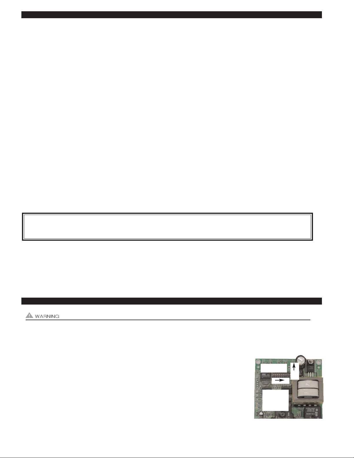
P1 & P2 PRE-CYCLE FAN PROVER STATUS CHECK
Pre-Cycle
Prover Status
Check Deactivated
The Pre-Cycle Prover Status Check is deactivated from the factory. When activated, the UC1
Universal Control checks across P1 & P2 safety circuit (PSA-1 Fan Prover) to verify that the Fan
Prover switch is “Open” upon a call for heat and not stuck “Closed”. Natural draft or winds may be
sufficient to close the PSA-1 Fan Prover switch contacts prior to a call for heat. Keeping the Prover
Status Check activated may cause nuisance lockouts. Push dip switch 9 up or “ON” to deactivate.
9
ON
PRE-PURGE SETTINGS (SEE “PRE-PURGE” ON PAGE 3 PRIOR TO SETTING)
12 12 12 12
0 Seconds 5 Seconds 20 Seconds 35 Seconds
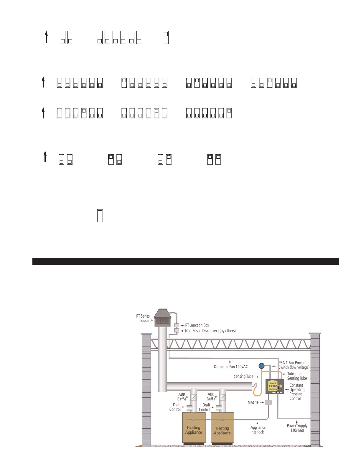
EXAMPLE OF DCOP1
& ROOFTOP INDUCER
INSTALLED WITH
MULTIPLE HEATERS
POST-PURGE SETTINGS (SEE “POST-PURGE” ON PAGE 3 PRIOR TO SETTING)
4348657 35678 345678 3 75468
4348657 35678 345678
4 Minutes 8 Minutes 16 Minutes
1 Minute0 Seconds 30 Seconds 2 Minutes
ON
ON
Pre-Purge
Post-Purge
Pre-Cycle
Prover Status
Check Deactivated
DIP SWITCH NUMBERING
1
ON
2
3
4
5
6
7
8 9
Page 6
5
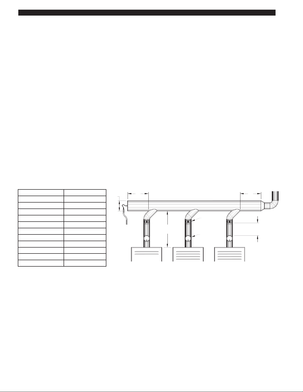
SIZING A COMMON MANIFOLD SERVING MULTIPLE HEATERS
The most important step towards assuring that individual heaters vented into a common manifold draft smoothly is to size the manifold large enough to negate the affects that velocity in the manifold has on the junctions of the heater vent connections.
Exhaust gases moving too quickly in a common vent manifold can amplify the draft at vent connectors by aspirating across the
connector opening and creating an amplified siphon affect. With a properly sized common vent manifold, velocities are maintained
below the point where they have a significant affect on the draft of the individual heater connections.
It is important to note that these sizing recommendations are for the common vent manifold only and that the typically smaller minimum vent diameter listed in the RT-Series Inducer selection table may be used for the remainder of the horizontal vent and chimney. The larger diameter vent common manifold should extend at least 2 diameters beyond the connection point of the last heater
farthest from the Inducer.
1. When in doubt, get help from Tjernlund Tech Service at 800-255-4208, push 0 and ask for technical assistance or
email fanmail@tjfans.com with details of your job.
2. If velocities are known, avoid exceeding 1200 FPM in the vent common manifold.
3. When possible use 45
O
Manifold Tee connections to the common vent manifold in the direction of the Inducer instead of 90
O
Tee connections.
4. Draft hoods/diverters create a disconnect from the heater’s flue outlet greatly buffering sudden changes in draft. Even though
the DCOP1 Constant Pressure Controller reacts quickly to maintain the draft/exhaust set-point, we still recommend installing
single acting barometric draft controls on fan assisted and power burner heaters. The barometric draft controls react instantly to
spikes in vent exhaust volume so that precise draft is always maintained.
5. If possible, locate the larger exhaust volume (i.e. higher BTU/hr. input) vent connections closer to the Inducer. This reduces the
affect of their exhaust on smaller volume connections.
6. The size of the common vent manifold should be at least 90% of the total area of all individual vent connections. See example
below.
Example: A vent layout is required for a job that consists of 4 heating appliances. 1 Appliance has an 8" diameter vent
connector, 2 appliances have 6" diameter vent connectors and 1 appliance has a 4" diameter vent connector.
Add these areas together:
1 x 0.3491 = 0.3491
2 x 0.1964 = 0.3928
1 x 0.0873 = 0.0873
______
0.8292
Total Area = 0.8292 Square Feet x 0.90 (90%) = 0.7463. In looking at the table above, this area is greater than a 10" diameter
pipe but smaller than a 12" diameter pipe. 12" diameter vent is the minimum size the common vent manifold diameter should be. It
is perfectly acceptable to be larger than this area if desired. It is also acceptable to have this area be reduced as the vent system
works backward towards the appliance furthest from the Inducer. In this example, the common vent manifold should extend at
least 24" past the connection point of the appliance farthest from the Inducer.
Breech Size Diameter Area (Square Feet)
3”
0.0491
4” 0.0873
5” 0.1364
6” 0.1964
8” 0.3491
10” 0.5454
12” 0.7854
14” 1.0690
16” 1.3960
18” 1.7670
20” 2.1820
BALANCING
BAROMETRIC
DRAFT CONTROL
(IF PRESENT)
BAFFLE
2D
MINIMUM
COMMON VENT MANIFOLD
MAINTAIN THE FLUE
OUTLET DIAMETER UNTIL
THE COMMON MANIFOLD
INSTALL THE BALANCING BAFFLE
AT LEAST 2 PIPE DIAMETERS ABOVE
THE BAROMETRIC OR FLUE OUTLET
D
2D
HEATER FURTHEST
FROM THE INDUCER
MINIMUM
FAN PROVER
SENSING TUBING TO
DCOP1 AND PSA-1
FIGURE 8054007 4/14/11
Page 7

6
The DCOP1 must be installed by a qualified installer (an
individual properly licensed and/or trained) in accordance
with all local codes or, in their absence, in accordance with
the appropriate National Fire Protection Association #31,
#54, #211 and the National Electrical Code.
All wiring from the DCOP1 to the appliance(s) must be appropriate Class 1 wiring as follows: installed in rigid metal conduit, intermediate metal conduit, rigid non-metallic conduit,
electrical metallic tubing, Type MI Cable, Type MC Cable, or
be otherwise suitably protected from physical damage
COP CONTROL POWER CONNECTIONS
Connect 115 VAC supply voltage to L & N terminals and
Ground wire to ground on COP control terminal block.
Important: Installer must supply overload and disconnect
protection.
INDUCER MOTOR & COOLING FAN CONNECTIONS
NOTE: The maximum distance wire can be ran from the
RT-Series Inducer 4 x 4 Junction box to the DCOP1 control
is 250 feet.
Cut Orange motor capacitor wire in RT-Series Inducer provided 4 x 4 Junction box and cap end with a wire nut that
previously went to RT-Series Inducer motor.
Connect the Orange Motor Capacitor lead to the MOTOR
ORG location on COP terminal strip.
Connect Red and White/Red motor leads from Rooftop
Inducer whip to MOTOR RED and WHT/RED location on
COP terminal strip.
Connect the Black & White Cooling Fan leads to COOL FAN
WHT and BLK location.
PSA-1 FAN PROVER CONNECTIONS
The UC1 (P1 and P2) safety circuit must be connected to
the PSA-1 Fan Prover Switch. These connections are done
on the PROVER P1(com) and P2 (n.o.) terminals on the
COP terminal strip. Leads are not polarity sensitive. If using
only millivolt appliances, the PSA-1 Fan Prover is not used.
A WHKE millivolt interlock kit which includes a Linear Limit
spillage switch is required.
1
WHITE
BLACK
FIGURE 8052077 5-4-11
INTERLOCK OPTIONS
INSTRUCTIONS FOR
SEE DCOP1
MOTOR
CAPACITOR
GROUND
WHITE
BLACK
RED
BROWN
WHITE / RED
COOLING FAN
THERMOSTAT
INDUCER
MOTOR
THERMOSTAT
WHT / RED
BLACK
BROWN
ORANGE
BROWN
RED
NUTS
ORANGE
BLACK
RED
WHT / RED
WHITE
WHITE
BLUEBLUEBLACK
INCLUDED 4 X 4 BOX
IMPELLER
WIRE
BLACK
P2
C FGND
P1
CALL
24V
DRY
JUMPER
J2
A B
RELAY
INTERLOCK
K2
K1
J1
XL
MN
XN
234 NL
MTR
1
N.O. COM ORG RED WHT BLK
1303284
WHT/
GRN
RED
PROVER MOTOR COOL FAN
P2
T11
P1
T7
N
GRN
L
WHT/RED
YEL
ORG
BLU
RED
WHT
BLK
T14
BLK
WHT
GRN
L
N
1303285
BLUE
YELLOW
WHITE
BLK
WHITE
BLK
T9
T6
T14
T11
T7
T10
WHITE / RED
ORG
RED
GROUND
ORANGE
ORANGE
PSA-1
SIDE VIEW
CUTAWAY
NL1
RT SERIES
COP
UC1
5 VDC BOARD-GENERATED
115 VAC
LEGEND
DO NOT SUPPLY POWER!
POWER SUPPLY
115 VAC
POWER.
4 FT. WHIP
PRE-WIRED
INCLUDED
115V
1
2
3
4
5
AMBER
BLUE
GREEN
RED
RED
6RED
L.E.D.S
1 THRU 9
DIP SWITCHES
UP = ON
WIRING CONNECTIONS BETWEEN DCOP1 AND ROOFTOP INDUCER
Page 8

7
UC1 UNIVERSAL CONTROL WIRING
All wiring from the UC1 to the appliance(s) must be appropriate Class 1 wiring as follows: installed in rigid metal conduit, intermediate
metal conduit, rigid non-metallic conduit, electrical metallic tubing, Type MI Cable, Type MC Cable, or be otherwise suitably protected
from physical damage
SEQUENCE OF OPERATION WITH UC1 UNIVERSAL CONTROL AND 24 VAC OR 115 VAC HEATER CONTROL CIRCUIT:
Control signal from thermostat, aquastat, primary control or gas valve is intercepted and routed to terminal "1" on UC1 terminal
strip. When terminal "1" is energized with either 24 VAC or 115 VAC, the COP controller energizes the Inducer motor. After draft is
established, the PSA-1 Fan Proving Switch closes energizing terminal "4", which completes the circuit allowing burner to fire.
NOTE:The burner will not fire until the 5 second factory set pre-purge time is finished. The Inducer will continue to run after the
burner has finished firing for the 2 minute factory set post-purge time. See "Pre / Post-Purge Settings" on page 3 for details.
The "1" input terminal on the UC1 can accept either a 24 VAC or 115 VAC control signal. IMPORTANT: The RED voltage
jumper must be positioned based on appliance interlock voltage 24V or 115V. If using the “DRY” contact activation method, use
terminals A & B on UC1 control and position the RED voltage jumper tab in the “DRY” position. See millivolt appliance interlock
diagram for further information. IMPORTANT: Only one interlock method (i.e. 24V, 115V or “Dry”) can be used with the UC1.
Multiple appliance interlocks require the use of our MAC-Series multiple appliance controls.
The steps listed under each diagram are intended as a supplement to the diagram. Wiring colors or designations may vary by
manufacturer. If you are unable to wire the UC1 as outlined in these instructions, call Tjernlund’s Customer Service Department
toll free at 1-800-255-4208 for assistance.
IMPORTANT: If the call for heat interlock signal or 115 VAC power is removed, the UC1 board will reset and any fault, if present,
will be stored in memory instead of displayed. See page 3, “Checking Memory for Last Fault Code”.
UC1 UNIVERSAL CONTROL WIRING SCHEMATIC
IMPORTANT: MORE THAN ONE INTERLOCK METHOD MAY BE APPLICABLE
In many cases it is easier to interlock with the thermostat/aquastat portion of the heater control circuit vs. the ignition module /
primary control portion of the heater control circuit. Review all of the wiring diagram options prior to choosing the best method.
K1
INTERLOCK
RELAY
J1
COM
J2
JUMPER
CALL
GREEN
RED
RED
AMBER
BLUE
MAC1E OR MAC4E
DEVICES. DO NOT
CONNECT POWER
WILL DAMAGE THE
OR F. DOING SO
TO P1, P2, C, GND
FOR TJERNLUND
GND
8
9
F
CONTROL.
AUXILIARY
342
675
C
1
P1
ON
P2
AS APPLIANCE INTERLOCK VOLTAGE.
RED JUMPER POSITION MUST BE THE SAME
DO NOT SUPPLY VOLTAGE
TO "A" OR "B".
IMPORTANT:
LED3LED5 LED4 LED2 LED1 LED6
NEUTRAL
LINE / HOT
COMMON /
CALL SWITCH
USER-PROVIDED
INTERCEPTED
CALL FOR
APPROVED CALL
OR
HEAT
"DRY"
P2 PROVER ON
TERMINAL STRIP
FACTORY WIRED
TO DCOP1 P1 AND
FACTORY WIRED TO
L AND N ON DCOP1
TO DCOP1 T6 AND T9
FACTORY CONNECTED
POWER TERMINALS
24 OR 115 VAC
APPROVED CALL BACK TO HEATER
INTERCEPTED CALL COMMON OR NEUTRAL
24 OR 115 VAC INTERCEPTED CALL FOR HEAT
5 VDC BOARD-GENERATED POWER
DO NOT SUPPLY POWER!
115 VAC
LEGEND:
TERMINAL 2:
TERMINAL 1:
TERMINAL 4:
FIGURE 8050029 3-28-11
LED
POWER
RED
DRY
24V
115V
(1 - 2)
PRE-PURGE SETTINGS
(3 - 8)
(9)
OPEN PROVER OPTION
POST-PURGE SETTINGS
RELAY
MTR
NO
INC.
9183006
TJERNLUND
PRODUCTS,
R
XL
K2
MOTOR
COM
MN
XN
NO
WARNING: Disconnect power supply from the DCOP1 and heating equipment when making wiring connections and servicing the
Inducer. Failure to do so may result in personal injury and/or equipment damage. LED #6 (RED) should be off with
power removed.
Page 9

8
MULTIPLE APPLIANCE INTERLOCKS
To interlock with one additional 24/115 VAC heater add the MAC1E. It is a stripped down auxiliary board version of the UC1 and
is powered by and communicates with the UC1 through a factory wired whip.
To interlock more than two 24/115 VAC heaters, add the MAC4E for a total of up to 5 heaters. It is powered by and communicates
with the UC1 through a factory wired whip. Consult factory for installations with more than 5 heaters.
To interlock a millivolt water heater and a 24/115 VAC furnace or boiler, add the WHKE and MAC1E.
MILLIVOLT HEATER INSTALLATIONS
Each millivolt appliance interlocked with the UC1 must have its own WHKE kit installed. The WHKE Gas Pressure Switch actuates
the Inducer through the A - B Dry contacts. The Linear Limit switch disables the heater in the event of a venting malfunction.
IMPORTANT: Each millivolt appliance interlocked with the UC1 must have its own Linear Limit spill switch.
MULTIPLE MILLIVOLT HEATER INSTALLATIONS
Multiple millivolt heaters can be installed by using the A-B dry contact terminals of the UC1, MAC1E or MAC4E. Wire each WHKE
gas pressure switch in parallel across A-B terminals of UC1, MAC1E or MAC4E. Wire Linear Limit safety switch into each individual millivolt heater. For further information consult factory or WHKE instructions.
POWER
REQUIREMENTS
EXTERNAL
POWER SWITCHING
CAPACITY
J1 / J2
JUMPER
SAFETY
CIRCUIT
ADD VENTER MOTOR
LOAD PLUS 1/2 AMP
FOR UC1 LOAD
EXTERNAL
CALL TRIGGER
METHODS
J1 / J2
P1 / P2
L / N
3 TO 4
T-BLOCK
T-BLOCK
(RELAY K1)
XL / XN
UC1 CONTROL
M & MTR
(RELAY K2)
T-BLOCK
A / B
24V
1 / 2
115V
1 / 2
OR
OR
USED TO JUMP CALL HOT (24 VAC) OR CALL LINE (115 VAC) FROM TERMINAL 1 TO TERMI N AL 3.
CONNECTED TO FAN PROVER.
1 mA @ 5 VDC. DO NOT SUPPLY POWER HERE.
REMOVE J1-J2 JUMPER IF A DIFFERENT VOLTAGE SOURCE IS PROVIDED TO TERMINAL 3.
120 VAC ±10 %, 50/60 Hz
MOTOR - 1 H.P. MAX. @ 120 VAC, 50/60 Hz
USER-PROVIDED 24 VAC AT TERMINALS 1 & 2. 1 = CALL HOT, 2 = COMMON. CONTROL
REQUIRES 5 mA @ 24 VAC TO TRIGGER. MOVE RED VOLTAGE JUMPER TO "24V" LOCATION.
3 mA @ 5 VDC. MOVE RED VOLTAGE JUMPER TO "DRY" LOCATION. DO NOT SUPPLY POWER.
USER-PROVIDED CONTACT CLOSURE FROM A TO B. SIZE CONTACT CLOSURE TO HANDLE
GENERAL PURPOSE - 15A @ 120 VAC, 50/60 Hz
DURING OPERATION THE CONTROL USES 50 mA MAX @ 120 VAC
MOTOR - 1 H.P. MAX. @ 120 VAC, 50/60 Hz
150 mA MAX @ 120 VAC, 50/60 Hz
CAN ONLY BE CONNECTED TO TJERNLUND-SPECIFIED AUXILIARY DEVICE
CIRCUIT PROTECTION PROVIDED BY INSTALLER
GENERAL PURPOSE - 15A @ 120 VAC, 50/60 Hz
RESISTIVE - 10A @ 28 VDC PILOT DUTY - 470 VA
USER-PROVIDED 115 VAC AT TERMINALS 1 & 2. 1 = CALL LINE, 2 = NEUTRAL. CONTROL
REQUIRES 1 mA @ 115 VAC TO TRIGGER. MOVE RED VOLTAGE JUMPER TO "115V" LOCATION.
UC1 CIRCUIT BOARD ELECTRICAL SPECIFICATIONS
Page 10

9
UC1 UNIVERSAL CONTROL CONNECTED WITH A SINGLE ZONE 24 VAC THERMOSTAT
115V
DRY
W
J2 J1
XL
RED JUMPER POSITION MUST BE THE SAME
AS APPLIANCE INTERLOCK VOLTAGE.
Y
R
R
Y
C
W
OF FURNACE
INTERNAL CONTROL
GG
THERMOSTAT
UNIVERSAL CONTROLLER
R
XN
FIGURE 8050031 3-28-11
FACTORY WIRED TO
L AND N ON DCOP1
JUMPER
CALL
LEGEND:
24 VAC
115 VAC
IMPORTANT:
24V
1. Connect W from t-stat to #1 on terminal block of UC1.
2. Connect #2 on UC1 terminal block to C on internal control terminal strip of furnace/boiler.
3. Connect #4 on UC1 terminal block to W on internal control terminal strip of furnace/boiler.
4. Make sure RED voltage jumper on UC1 is on 24V.
NOTE: If burner safety control goes out on lockout, the Inducer will continue to run as long as a call for heat is present.
UC1 BURNER INTERLOCK WIRING DIAGRAMS
UC1 UNIVERSAL CONTROL CONNECTED WITH A 24 VAC ELECTRONIC IGNITION MODULE
OR
WH
PV
YE
(8)
SPARK (9)
OR
UNIVERSAL CONTROLLER
FIGURE 8050030 3-28-11
R
LEGEND:
24 VAC
115 VAC
XNXL
J1
IMPORTANT:
JUMPER
24V
CALL
J2
115V
DRY
FACTORY WIRED TO
L AND N ON DCOP1
RED JUMPER POSITION MUST BE THE SAME
AS APPLIANCE INTERLOCK VOLTAGE.
24V GND (5)
BNR GND (4)
HONEYWELL IGNITION
MV / PV (2)
CONTROL
MV (1)
OR
PV (3)
24V (6)
(7)
WH
YE
GR
YE
PI
GAS VALVE
PV
MV
MV
GR
1. Remove the wire on MV at gas valve and connect it on #1 on UC1 terminal block.
2. Connect #2 on UC1 terminal block to MV/PV.
3. Connect #4 on UC1 terminal block to MV on gas valve.
4. Make sure RED voltage jumper on UC1 is on 24V.
Page 11

10
UC1 UNIVERSAL CONTROL AND WHKE INTERLOCK KIT
CONNECTED WITH A MILLIVOLT APPLIANCE
SWITCH ARE INCLUDED WITH WHKE KIT.
950-0470 JUNCTION ADAPTER AND GAS PRESSURE
950-0470 (JA1) THERMOCOUPLE JUNCTION ADAPTER.
LINEAR LIMIT SPILL SWITCH IN SERIES WITH HIGH LIMIT
ON 750 MILLIVOLT (POWER PILE) WATER HEATERS WIRE
(ECO) OF WATER HEATER. LINEAR LIMIT SPILL SWITCH,
30 MILLIVOLT WATER HEATERS REQUIRE USE OF THE
SPILL SWITCH
LINEAR LIMIT
950-0470 (JA1)
THERMOCOUPLE
JUNCTION ADAPTER
SWITCH
J1
UNIVERSAL CONTROLLER
IN THIS APPLICATION. SPILL SWITCH MUST BE INTERLOCKED
WITH HEATING EQUIPMENT AS SHOWN.
SAFETY CIRCUIT ACROSS P1 & P2 OF UC1 IS NOT UTILIZED
R
XNXL
PRESSURE
WHKE GAS
RED JUMPER POSITION MUST BE THE SAME
AS APPLIANCE INTERLOCK VOLTAGE.
IMPORTANT:
115V
J2
CALL
JUMPER
24V
DRY
POWER!
SUPPLY
DO NOT
MILLIVOLT
FIGURE 8050033 3-29-11
BOARDPOWER.
115 VAC
LEGEND:
5 VDC
GENERATED
GAS
VALVE
FACTORY WIRED TO
L AND N ON DCOP1
Each millivolt appliance interlocked with the UC1 must have its own WHKE kit installed. The WHKE Gas Pressure Switch actuates
the Inducer through the A - B Dry contacts. The Linear Limit switch disables the heater in the event of a venting malfunction.
IMPORTANT: Each millivolt appliance interlocked with the UC1 must have its own Linear Limit spill switch.
1. Wire WHKE Gas Pressure Switch in series with A and B terminal on UC1. Do not supply voltage to A and B terminals.
2. Wire WHKE Linear Limit in series with thermocouple junction adapter or high limit ECO of water heater.
3. Make sure RED voltage jumper on UC1 is in the DRY position.
NOTE: If only venting millivolt appliances the PSA-1 Fan Proving Switch is not required, see WHKE instructions for
complete details.
UC1 UNIVERSAL CONTROL CONNECTED WITH A 24 OR 115 VAC STANDING PILOT
JUMPER
115 VAC
24 OR 115 VAC
XNXL
J2 J1
LEGEND:
UNIVERSAL CONTROLLER
AS APPLIANCE INTERLOCK VOLTAGE.
RED JUMPER POSITION MUST BE THE SAME
115V
CALL
24V
DRY
IMPORTANT:
FIGURE 8050032 3-28-11
FACTORY WIRED TO
L AND N ON DCOP1
24V OR 115V GAS VALVE
TR
COMTHHOT
INTERNAL CONTROLS
OF FURNACE/BOILER
B2
COM
Aquastat
T-stat
B1
HOT
1. Remove the wire on TH or HOT of gas valve and connect it on #1 on UC1 terminal block.
2. Connect #2 on UC1 terminal block to TR or Common.
3. Connect #4 on UC1 terminal block to TH or HOT on gas valve.
4. Make sure RED voltage jumper on UC1 is on 24V or 115V depending on control voltage.
Page 12

11
UC1 UNIVERSAL CONTROL CONNECTED TO A HONEYWELL R7184 SERIES OR EQUIVALENT
PRIMARY CONTROL WITH A LINE VOLTAGE THERMOSTAT OR AQUASTAT
Jumper
Low Voltage
or Aquastat Control
Line Voltage Thermostat
Ignitor
JUMPER
CALL
LEGEND:
115 VAC
IMPORTANT:
AS APPLIANCE INTERLOCK VOLTAGE.
RED JUMPER POSITION MUST BE THE SAME
J2 J1
XN
UNIVERSAL CONTROLLER
XL
115V
DRY
24V
Limit
SUPPLY
60 Hz
115 VAC
OIL VALVE
L2
T
T
L1
R7184
Limit
Oil Valve
R
BURNER MOTOR
IGNITION TRANS
A
Motor
Intermittant
Interrupted
A
Cad Cell
Alarm
Burner
FIGURE 8050035 3-29-11
FACTORY WIRED TO
L AND N ON DCOP1
1. Disconnect burner motor wire off the R7184.
2. Connect burner motor terminal of R7184 to #1 on UC1 terminal block.
3. Connect #2 on UC1 terminal block to L2 or N.
4. Connect #4 on UC1 terminal block to burner motor wire removed from R7184.
5. Make sure RED voltage jumper on UC1 is on 115V.
UC1 UNIVERSAL CONTROL CONNECTED TO A GAS OR OIL BURNER WITH AN AQUASTAT
FROM PRIMARY CONTROL / CAD CELL RELAY.
WHEN INTERLOCKING WITH AQUASTAT DO NOT DISCONNECT BURNER MOTOR
CAUTION:
AS APPLIANCE INTERLOCK VOLTAGE.
IMPORTANT:
RED JUMPER POSITION MUST BE THE SAME
RELAY OR GAS VALVE
JUMPER
CALL
LEGEND:
115 VAC
L2L1C2
C1
B1
B2
AQUASTAT
24V
DRY
115V
J2 J1
XL
N
L1
PRIMARY CONTROL, BURNER
LINE VOLTAGE OIL BURNER
UNIVERSAL CONTROLLER
R
XN
FIGURE 8050034 3-29-11
FACTORY WIRED TO
L AND N ON DCOP1
1. Disconnect B1 from L1 of oil burner primary control, burner relay or hot of gas valve and reconnect to #1 on UC1 terminal block.
2. Connect #2 on UC1 terminal block to B2 or N.
3. Connect #4 on UC1 terminal block to the L1 on line voltage oil burner primary control, burner relay or gas valve.
4. Make sure RED voltage jumper on UC1 is on 115V.
NOTE: If burner safety control goes out on lockout, the Inducer will continue to run as long as a call for heat is present.
Page 13

12
UC1 UNIVERSAL CONTROL CONNECTED TO AN OIL-FIRED FURNACE WITH A
HONEYWELL T87 OR EQUIVALENT NON-POWERED THERMOSTAT
R
XL XN
J1
HONEYWELL T87 OR EQUIVALENT
NON-POWERED THERMOSTAT
115V
J2
LOW VAC
POWER.
DO NOT SUPPLY POWER!
115 VAC
LEGEND:
5 VDC BOARD-GENERATED
IMPORTANT:
BACKFEEDS OR SHORT
REMOVE JUMPER TO AVOID
24V
DRY
CIRCUITS.
FIGURE 8050037 3-29-11
FACTORY
WIRED TO
ON DCOP1
L AND N
IMPORTANT:
RED JUMPER POSITION MUST BE THE SAME
AS APPLIANCE INTERLOCK VOLTAGE.
PRIMARY CONTROL
UNIVERSAL CONTROLLER
OR EQUIVALENT
BLACK
ORANGE
WHITE
WIRED
FACTORY-
R8184 SERIES
O
HONEYWELL
W
F
F
B
T
T
1. IMPORTANT: Remove J1 & J2 Call Jumper on UC1 to avoid backfeeds or short circuits.
2. Connect T87 or Equivalent non-powered thermostat to A and B terminals on UC1.
3. Remove T T Jumper from R8184 or equivalent Primary Control.
4. Connect #3 on UC1 terminal block to T terminal of Primary Control.
5. Connect #4 on UC1 terminal block to remaining T terminal of Primary Control.
6. Make sure RED voltage jumper on UC1 is on DRY.
NOTE: If burner safety control goes out on lockout, the Inducer will continue to run as long as a call for heat is present.
Jumper
Low Voltage
or Aquastat Control
Limit
JUMPER
CALL
LEGEND:
115 VAC
24V
DRY
115V
IMPORTANT:
AS APPLIANCE INTERLOCK VOLTAGE.
RED JUMPER POSITION MUST BE THE SAME
J1
XL XN
UNIVERSAL CONTROLLER
J2
SUPPLY
60 Hz
Line Voltage Thermostat
10 FLA / 60 LRA
500 VA
IGNITION TRANS
BURNER MOTOR
115 VAC
T Red/White
BlackT
WhiteF
F Orange
BlueA
R
OIL VALVE
0.3 A, AC
VioletA
Alarm
FIGURE 8050036 3-29-11
FACTORY WIRED TO
L AND N ON DCOP1
1. Disconnect burner motor wire off the Orange on Carlin.
2. Connect burner motor terminal Orange of Carlin to #1 on UC1 terminal block.
3. Connect #2 on UC1 terminal block to L2 or N
4. Connect #4 on UC1 terminal block to burner motor wire removed from Orange of Carlin.
5. Make sure RED voltage jumper on UC1 is on 115V.
UC1 UNIVERSAL CONTROL CONNECTED WITH A CARLIN 40200, 42230, 48245, 50200, 60200
SERIES OR EQUIVALENT AND A LINE VOLTAGE THERMOSTAT OR AQUASTAT
Page 14

13
UC1 UNIVERSAL CONTROL CONNECTED WITH A HONEYWELL R8184 SERIES
OR EQUIVALENT PRIMARY CONTROL AND A BURNER MOTOR POST-PURGE
L2 OR B2
CONNECT TO
CONNECT TO
L1 OR B1
TRANS
IGNITION
MOTOR MOTOR
VENTER
SERIES OR EQUIVALENT
HONEYWELL R8184
BLACK
JUMPER
CALL
LEGEND:
115 VAC
24V
DRY
115V
J2 J1
XL
IMPORTANT:
T
T
F
F
B
ORANGE
WHITE
O
W
OIL VALVE
THERMOSTAT
MMTRN
BURNER
XN
UNIVERSAL CONTROL
AS APPLIANCE INTERLOCK VOLTAGE.
RED JUMPER POSITION MUST BE THE SAME
FIGURE 8050039 3-29 - 11
FACTORY
WIRED TO
L AND N
ON DCOP1
1. Separate the burner motor wire and ignition transformer from the Orange wire of R8184.
2. Connect the Orange of R8184 to #1 on UC1 terminal block.
3. Connect #2 on UC1 terminal block to White on R8184 and L2 or B2.
4. Connect the HOT wire of oil solenoid valve to #4 on UC1 terminal block and neutral wire to White or N.
5. Connect burner motor and ignition transformer HOT wires to M terminal on UC1 and neutrals to White or N.
6. Make sure RED voltage jumper on UC1 is on 115V.
UC1 UNIVERSAL CONTROL CONNECTED TO A HONEYWELL
R8184 SERIES OR EQUIVALENT PRIMARY CONTROL
24V
DRY
115V
J2
XL
J1
AS APPLIANCE INTERLOCK VOLTAGE.
IMPORTANT:
RED JUMPER POSITION MUST BE THE SAME
XN
UNIVERSAL CONTROLLER
BLACKWHITE
BURNER MOTOR
IGNITION TRANS
OR EQUIVALENT
R8184 SERIES
HONEYWELL
BLACK
ORANGE
WHITE
R
FIGURE 8050038 3-29-11
FACTORY
WIRED TO
ON DCOP1
L AND N
WHITE
L2 OR B2
CONNECT TO
CONNECT TO
L1 OR B1
JUMPER
CALL
LEGEND:
115 VAC
1. Separate the Black burner motor wire from the Orange wire of R8184 Primary Control.
NOTE: Do not separate the ignition transformer wire from the Orange.
2. Connect Orange wire of R8184 to #1 on UC1 terminal block.
3. Connect #2 on UC1 terminal block to White on R8184 and L2 or B2.
4. Connect Black of burner motor to #4 on UC1 terminal block.
5. Make sure RED voltage jumper on UC1 is on 115V.
Page 15

14
HOW THE DRAFT COP WORKS
When an intercepted call for heat contact closure or voltage is sensed at the UC1 interlock terminal strip the COP control is activated through the UC1 MTR and N outputs. Once powered the COP control energizes the Inducer motor and speeds it up enough
to meet the pressure set point. When the PSA-1 Fan Prover switch closes a 5 second factory set pre-purge delay (Adjustable from
0 to 35 seconds) occurs prior to completing the circuit back to the interlocked heater. The COP will increase or decrease the
inducer speed to maintain set point as flue gas temperatures, volumes and stack effect change. The COP is self compensating for
changes in building pressure and outdoor winds. When the call for heat is satisfied the Inducer will continue to operate for a 2
minute factory set post-purge (Adjustable from 0 to 16 minutes).
VENT PIPE SENSING SAMPLING TUBE & PSA-1 FAN PROVER LOCATION & INSTALLATION
SENSING SAMPLING TUBE LOCATION
The sensing tube should be installed in the cap of a tee or at the rear of a common manifold, in back of the vent connector that is farthest from the Inducer. The tee is necessary
so that only static pressure is measured, (See Diagram A). If the draft sensing tube is
installed in the side of a vent pipe it will also measure velocity pressure, giving an incorrect signal back to the DCOP1 Control. If mounting on the side of the pipe is unavoidable,
the sensing tube should be flush
to the interior wall of the vent pipe. Avoid sampling near
or in elbows. Vent connections should be sealed to prevent leakage or entrainment.
SENSING SAMPLING TUBE INSTALLATION
1. Using a sharp drill bit to reduce burr, drill a 1/4" hole for draft sensing tube.
Screw sensing tube bracket to pipe with sampling hole centered, (See Diagram B).
2. Insert stainless steel sensing tube through 1/4" hole enough to just penetrate interior
of vent pipe and lock in place with compression nut, (See Diagram B). With the Rooftop
Inducer on, a reading with a draft gauge can be used to determine when interior
of pipe has been penetrated.
PSA-1 FAN PROVER INSTALLATION
IMPORTANT: PSA-1 Fan Proving Switch diaphragm must be
mounted in a vertical position. Firmly insert flexible tubing on
sampling tube and connect with a “T” connector to both DCOP1
sensing port and PSA-1 Proving Switch nipple marked (LOW).
Leave other PSA-1 Proving Switch port open to room atmosphere.
See Diagram J on page 15 for where to install tubing “T”
connectors. Make sure there are no sharp bends or kinks in
tubing.
ADJUSTING THE PRESSURE (DRAFT) SET POINT & BALANCING INDIVIDUAL HEATER DRAFT
Adjusting the COP system is a two step process. In the first step initial rough adjustments are made. This allows time to make fine
tuning adjustments without distractions from the heater(s) firing sequence.
Prior to System Activation
1. Close the balancing baffle in each vent connection riser, (See Diagram C).
2. Adjust barometric draft controls if present to their most weighted or hardest to open position for each heater, (See Diagram D).
3. Turn adjustment screw on PSA-1 Fan Prover Switch counter-clockwise until it stops, (See Diagram E).
D
2D
MINIMUM
PSA-1 FAN
DCOP1 AND
SENSING
PROVER
TUBING TO
BEHIND THE HEATER FURTHEST FROM INDUCER
BE LOCATED TWICE THE MANIFOLD DIAMETER
IF POSSIBLE, THE SENSING TUBE SHOULD
HEATER FURTHEST
FROM THE INDUCER
BALANCING
BAROMETRIC
DRAFT CONTROL
(IF PRESENT)
BAFFLE
DIAGRAM A
DIAGRAM B
1/4” STAINLESS STEEL
SENSING TUBE BEND MUST
FACE UPWARD
COMPRESSION FERRULE
COMPRESSION NUT
SAMPLING PORT CENTERED
OVER 1/4” HOLE
DIAGRAM C
DIAGRAM D DIAGRAM E
Page 16

15
4. Verify that slot on set point adjustment pot for the COP controller is aligned with the "20" hash mark, (See Diagram F).
5. Disconnect the lead(s) connected to terminal #4 of the UC1 circuit board and MAC-Series multiple appliance interlock controls.
This will prevent any interlocked burners from firing, (See Diagram G). On Millivolt appliances turn thermostat off.
VERIFYING SYSTEM OPERATION
With 115 VAC supply power to the L and N of the Draft COP black terminal strip LED #6 should be solid RED and LED #5 on UC1
should be blinking RED. Any interconnected MAC-Series circuit boards should have a solid RED #9 power LED, (See Diagram H).
1. Adjust thermostat of any heater to call for heat. This should cause the following sequence of LED's to light, (See Diagram I).
Amber: Call for heat intercepted
Green: Draft Cop Control and Inducer activated (Green LED is present on UC1 only)
Blue: PSA-1 Prover Switch Closed to allow burner to fire
2. Verify that the Inducer activates by seeing the draft pressure increase (more negative) on your draft gauge as measured with a
tee at draft sensing position at rear end of common manifold or vent connector, (See Diagram J). Gradually adjust the pot on
the COP controller circuit board clockwise. The Inducer should speed up increasing the negative draft pressure. Slowly adjust
the pot on the COP controller counter-clockwise until the draft pressure is maintained at -0.10” w.c.. NOTE: Turning the adjustment pot too far counter-clockwise will cause the Inducer to stall or not be able to start. Readjust clockwise if necessary.
3. Disrupt the call for heat. The Inducer should continue to operate at a consistent negative draft pressure for a the 2 minute postpurge period (Adjustable from 0 to 16 minutes).
4. Shut off disconnect switch(s) to Heater(s) and re-install the leads removed from the #4 terminal(s) of the UC1 heater interlock
terminal strip. On millivolt appliances turn thermostat back to the on position.
DIAGRAM H
DIAGRAM I
DIAGRAM J
DIAGRAM F
DIAGRAM G
TO DCOP1 JUNCTION
BOX SENSING TUBE
PORT
PSA-1
FAN PROVER
DIAPHRAGM
IN VERTICAL
POSITION
PSA-1
FAN PROVER
DIAPHRAGM
IN VERTICAL
POSITION
TO PRESSURE SENSING TUBE IN VENT
COMMON MANIFOLD
TUBING WITH DRAFT GAUGE REMOVED
TUBING WITH DRAFT GAUGE
TO DCOP1 JUNCTION
BOX SENSING TUBE
PORT
TO
DRAFT
GAUGE
TO PRESSURE SENSING TUBE IN VENT
COMMON MANIFOLD
DCOP1 DRAFT
ADJUSTMENT POT
AND SCALE. CLOCKWISE WILL INCREASE
DRAFT.
RED LED #6 INDICATES
115 VAC POWER IS
SUPPLIED TO UC1
BOARD
REMOVE #4 WIRE FROM
UC1, MAC1E OR MAC4E
CONTROL. ON MILLIVOLT
APPLIANCES TURN THERMOSTAT OFF.
RED LED #5 FLASHES
EVERY 3 SECONDS WITHOUT A CALL FOR HEAT TO
INDICATE UC1 IS WORKING PROPERLY.
LED #1 AMBER - INDICATES CALL FOR HEAT
LED #3 GREEN - DCOP1 AND INDUCER ACTIVATED
LED #2 BLUE - PSA-1 PROVER CLOSED, BURNER FIRES
#3
G
R
N
#2
B
L
U
#1
A
M
B
#6
P
W
R
UC1 BOARD
Page 17

16
ADJUSTMENT OF DRAFT SET POINT, BALANCING BAFFLE(S) AND BAROMETRIC DRAFT CONTROL(S)
Sample Draft at heater manufacturer’s recommended point. If not specified, drill a small sampling hole in vertical riser midway
between flue outlet and Balancing Baffle. Heaters with draft hoods/diverters typically require a slight negative draft between
-0.02" to -0.03" w.c. Heaters with barometric draft controls typically require a negative draft of between -0.02" to -0.05" w.c.
1. Turn on the disconnect or thermostat for the heater farthest from the Inducer and establish call for heat.
2. Gradually open the Balancing Baffle until the manufacturer’s recommended draft range is achieved and lock in place. Wait a few
minutes for heater flue gas temperature to reach steady state and adjust weight on Barometric Draft Control, if present, so that
the damper is slightly open. Re-adjust Balancing Baffle if necessary to maintain draft in recommended range.
3. Repeat steps 1 and 2 for each heater, one heater at a time, moving towards the Inducer.
4. When all heaters have been adjusted fire heaters randomly to assure proper light off and then all together to verify that at the
heating system’s maximum firing rate proper draft levels are maintained for each heater.
5. Pinch the silicon sampling tube closed near the connection to the PSA-1 Fan Prover switch and remove from switch, keeping
seal tight. This will keep the Inducer operating while allowing the PSA-1 Fan Prover switch to open, disrupting the P1 and P2
UC1 prover safety circuit. After a 10 second delay built into the UC1 Safety circuit the Blue Fan Prover #2 LED should go out
and the burners should be disrupted or will not ignite on a call for heat. Reinstall tubing to the PSA-1 Fan Prover.
FINAL OPERATION AND DRAFT CHECK
The PSA-1 Fan Proving Switch is designed to disable the appliance gas valve(s)
or burner motor(s) upon Inducer failure only! It is not designed and cannot
replace, regular vent system inspection, appliance servicing and combustion
testing.
1. Close all doors and windows of the building. If the appliance is installed in
a utility room or closet, close the entrance door to this room. Close fireplace dampers.
2. Turn on clothes dryer and all exhaust fans such as range hoods, bathroom
exhausts and whole house fans to maximum speeds. Do not operate a fan
used strictly for Summer exhausting.
3. Following the appliance manufacturer’s instructions, place the appliance in
operation, set thermostat for continuous operation.
4. Verify that Inducer operates first, prior to burner ignition. Watch to make sure burner lights off properly.
GAS
After allowing appliance(s) to operate for 15 minutes, follow the appliance manufacturer’s instructions to verify that the recommended draft is present. In general, most gas appliances will operate safely with flue outlet draft levels from -0.02 to -0.05" W.C..
If the draft is excessive, make necessary adjustments to the balancing baffle, barometric control or DCOP1 draft setting. As a
cross check, a candle or match can be held adjacent to the draft hood or barometric control to verify flame/smoke is being drawn
into, and not rolling out of edge of the relief opening, (See Diagram k). If exhaust gases are escaping from the relief opening of the
draft hood or barometric control, the equipment should not be operated until proper adjustments or repairs are made to provide
adequate draft levels.
OIL
After allowing equipment to operate for 15 minutes, make necessary adjustments to the primary air intake and barometric draft
control to comply with the manufacturer recommended over-fire draft and CO
2 requirements of the burner. In most cases, the
over-fire draft should be in a range of -.02” to -.04” W.C. If adjustments to the primary air intake and barometric draft control do not
provide the required over-fire draft, make necessary adjustments to the balancing baffle or DCOP1 draft setting. Measure over-fire
draft and CO
2
after adjustments.
5. Next, turn on all other fuel-burning appliances within the same room so they will operate at their full input. Repeat Step 3 above,
checking the draft on each appliance.
TROUBLESHOOTING ELECTRICAL PROBLEMS
The following guide is intended to be used if a problem occurs during the use of the Inducer and UC1. It may be necessary to
measure voltage during troubleshooting. Extreme caution must be exercised to prevent injury. If you are unable to determine
the defective part with the use of this guide, call your Tjernlund distributor or Tjernlund Products direct at 1-800-255-4208 for further assistance.
PROPER
DRAFT
ESTABLISHED
PROPER
DRAFT
ESTABLISHED
DIAGRAM K
Page 18

17
IMPORTANT: If the call for heat interlock signal or 115 VAC power is removed, the UC1 board will reset and any fault, if present,
will be stored in memory instead of displayed. See “Checking Memory for Last Fault Code” below.
LED INDICATOR LIGHTS
LED #1 (Amber) Appliance call for heat.
LED #2 (Blue) Safety circuit through P1 & P2 (PSA-1 Fan Prover and/or Limit). Indicates PSA-1 switch is closed during run
cycle. Burner circuit is energized with Interlock Relay contact closure from terminal 3 to 4.
LED #3 (Green) Power switched to COP controller from MTR & N.
LED #4 (Red) Status / Fault indicator.
LED #5 (Red) Used as a status indicator.
LED #6 (Red) 115 VAC power supplied to board.
LED STATUS INDICATORS
LED #4 & #5 (Red) Flashing Alternately = Inducer in Pre-purge. (Pre-Purge options 0, 5, 20, 35 seconds)
LED #4 & #5 (Red) Flashing in Unison = Inducer in Post-Purge. (Post-Purge options 0, 30 seconds or 1, 2, 4, 8, 16 minutes)
LED #4 (Red) Flashes Continuously* = PSA-1 Fan Prover opened for more than 10 seconds during burner cycle.
(Inducer will run for 10 minutes, attempting to close Fan Prover)
LED #5 (Red) Flashing Intermittently = With no call for heat, flashes 3 seconds on / 3 seconds off if microcontroller
is working properly.
LED FAULT INDICATORS
Fault conditions are indicated by counting the number of times LED #4 (Red) flashes.
LED #4 (Red) Flashes 2 Times PSA-1 Fan Prover was in electrically closed position prior to Inducer operation.
LED #4 (Red) Flashes 3 Times* PSA-1 Fan Prover does not close within 60 seconds after call for heat.
LED #4 (Red) Flashes 4 Times* PSA-1 Fan Prover opened during cycle and did not close within 10 minutes of Inducer operation.
LED #4 (Red) Flashes 5 Times* PSA-1 Fan Prover opened for more than 10 seconds during burner cycle but closed within 10 minutes.
* Investigate cause of PSA-1 Fan Prover short cycling such as; firing burner at capacities or temperatures exceeding Inducer
limits, excessive vent pipe runs, plugged / kinked Fan Prover sensing tube, PSA-1 Fan Prover setpoint too high or DCOP1 draft
setpoint too low. Adjustment may be required.
CHECKING MEMORY FOR LAST FAULT CODE
IMPORTANT: Prior to accessing the fault code memory, note the settings of the dip switches so that they can be returned to their
original Pre / Post-Purge positions. When power is supplied to the DCOP1 use caution when moving UC1 dip switches.The last
fault code can be retrieved at any time by setting all dip switches 1-8 to the up, or "on" position. The last fault code, or lack there
of, will be indicated by counting the number of times LED #4 (Red) flashes. By moving any of the dip switches back to their original
position, the fault code will be cleared. NOTE: The DCOP1 must have its 115 VAC power supply present when any of the UC1
(1-8) dip switches are moved back to their original position for the fault code to clear.
SYMPTOM 1: INDUCER OPERATES CONTINUOUSLY
Verify the Inducer is not in post-purge mode which has been factory set for 2 minutes (Adjustable from 0 to 16 minutes). LED #4 &
#5 (Red) will flash in unison during post-purge. An Inducer pre-purge has been factory set for 5 seconds (Adjustable from 0 to 35
seconds) LED #4 & #5 (Red) will flash alternately during pre-purge. See “Pre / Post-Purge Settings” on page 3.
Verify that LED #1 (Amber) is not lit.
Yes, LED #1 (Amber) is lit: Check interlock wiring. Confirm burner control(s) are functioning properly. UC1 control is receiving
constant call for heat signal.
LED #1 (Amber) is not lit: Replace UC1 circuit board part number 950-8804.
SYMPTOM 2: INDUCER MOTOR DOES NOT OPERATE
Verify that UC1 control has power, LED #6 (Red) should be lit. Verify that LED #4 (Red) is not flashing. See “LED Status & Fault
Indicators” above if flashing. Verify RED voltage selection jumper corresponds with interlock voltage (i.e 24V, 115V or “Dry”).
No, Check circuit breaker, disconnect switches and Inducer wiring to DCOP1.
Yes, LED #6 (Red) is lit: Verify that the interlocked burner is calling for heat, LED #1 (Amber) should be lit.
No, LED #1 (Amber) is not lit: Verify interlock wiring and that thermostat/aquastat is adjusted to call for heat. Verify that the RED
voltage selection jumper is installed so that it matches the voltage of the interlocked burner.
Yes, LED #1 (Amber) is lit: Verify Prover safety circuit fault does not exist. See, “LED Status & Fault Indicators” above.
IMPORTANT: Fault codes will automatically be displayed after a fault condition occurs. If the call for heat interlock signal
or 115 VAC power is removed, the UC1 board will reset and the fault will be stored in memory instead of displayed. Any
new fault will replace any previous fault.
Page 19

18
If faults exist check PSA-1 Prover P1 & P2 safety circuit. PSA-1 Fan Prover setpoint, DCOP1 draft setpoint or balancing of system
may be required. See “Adjustment of Draft Setpoint, Balancing Baffle(s) and Barometric Draft Control(s)” on page 16.
If no faults exist, with a call for heat established check for 115 VAC across UC1 terminals N and MTR which should be connected
to DCOP1 terminals T6 and T9.
Voltage present: Verify wiring connections between DCOP1 and RT-Series Inducer. Check adjustment pot on DCOP1. Too low of
an adjustment may stall Inducer. Adjust clockwise to see if Inducer speeds up. If Inducer does not speed up and there is 115 VAC
across the T6 and T9 terminals on DCOP1 control, verify that Inducer motor capacitor is good. Disconnect the wire from capacitor
that is connected to the ORG Motor terminal on DCOP1 control. Reconnect Orange wire from Inducer capacitor in 4 x 4 electrical
box to the Orange wire that should be capped off coming from RT-Series Inducer whip. Remove the Red and White/Red leads that
were connected to the MOTOR RED and WHT/RED connection on DCOP1 and provide 115 VAC to them. If motor runs, replace
COP control circuit board part number 950-8805. If motor does not run, verify capacitor is good. Replace RT-Series Inducer
capacitor or motor if necessary.
No voltage present: Replace UC1 circuit board part number 950-8804.
SYMPTOM 3: INDUCER OPERATES, BUT BURNER DOES NOT
For any newly established call for heat the Inducer will run for 60 seconds to try to close the UC1 Fan Prover circuit (P1 to P2). If
circuit can not be made within 60 seconds LED #4 (Red) will flash 3 times, indicating a prover check circuit fault on UC1 start up.
NOTE: The UC1 safety circuit and LED #4 (Red) will be reset if the call for heat interlock signal or 115 VAC power is removed. If
the fan prover makes on start up, but breaks for more than 10 seconds during the burner cycle, LED #4 will flash continuously indicating a prover circuit fault. The Inducer will continue to run for 10 minutes to try to make the prover circuit as long as a call for
heat exists. If Prover does not make within 10 minutes, the UC1 will shut down and LED #4 (Red) will flash 4 times indicating a
prover circuit fault. Remove the call for heat and then reestablish to reset the UC1 prover safety circuit (P1 to P2) & LED #4 (Red).
Verify that LED #2 (Blue) is lit.
Yes, LED #2 (Blue) is lit: Verify that "call jumper" is connected from J1 to J2 on UC1 circuit board if using typical wiring where sup-
ply voltage from terminal 1 is routed to terminal 3 through “call jumper” then to 4 when appliance interlock relay makes. With call
for heat established, verify that wiring is correct by measuring voltage between terminals 1 & 2 and 2 & 4 of UC1 terminal strip.
Voltage should be the same in both cases, if not rewire per appropriate diagram or confirm burner control(s) are functioning properly. NOTE: If outside power source is provided to terminal 3 and switched to terminal 4 check for continuity between 3 and 4
with leads disconnected from 3 and 4 and Inducer operating. If there is no continuity between 3 and 4 and the Blue LED is lit,
replace UC1 circuit board part number 950-8804. If continuity is present, recheck interlock wiring and burner control(s). If using the
A-B dry contacts for millivolt installations make sure system Linear Limit Spillage switch on draft hood/diverter has not tripped.
Reset if necessary.
No, LED #2 (Blue) is not lit: Remove power from UC1 and confirm dip switch #9 is up or “on” to deactivate the Pre-Cycle Fan
Prover status check. Keeping the Pre-Cycle Prover Status Check activated may cause nuisance lockouts. Remove P1 and P2
prover leads off of PSA-1 Fan Prover switch and jumper together. Reestablish power and call for heat. After 5 second factory set
Inducer pre-purge (Adjustable from 0 to 35 seconds), LED #2 (Blue) should light.
No, LED #2 (Blue) does not light: Replace UC1 circuit board, part number 950-8804.
Yes, LED #2 (Blue) lights up: The PSA-1 Fan Proving switch may not be closing, wiring connections are incorrect/broken or burner
control(s) are not functioning properly. With Inducer running, verify that Inducer performance is sufficient to close Fan Prover contacts by checking for continuity across switch. Replace PSA-1 Fan Prover leads from P1 and P2 back on Fan Proving switch.
No, continuity is not present: Confirm that burner is not firing at capacities or temperatures exceeding Inducer limits. Check for
excessive vent pipe runs, high winds, plugged / kinked Fan Prover sensing tube or a faulty Fan Prover switch. Perform
“Adjustment of Draft Set Point, Balancing Baffles(s) and Barometric Draft Controls” procedure on page 16 to verify if set point
adjustment is necessary on the DCOP1 or PSA-1 Fan Prover. If everything checks out okay, replace PSA-1 Fan Prover.
Yes, continuity present: Recheck interlock wiring and burner control(s).
HOW TO OBTAIN SERVICE ASSISTANCE
1. If you have any questions about your DCOP1 or if it requires adjustment or repair, we suggest that you contact your installer,
contractor or service agency.
2. If you require technical information contact Tjernlund Products, Inc. at 1-800-255-4208 with the following information.
1. Model of the Inducer that DCOP1 is interlocked with as shown on the label attached to Inducer.
2. Name and address of installer and any service agency who performed work on the system.
3. Date of original installation and dates any service work was performed.
4. Details of the problem as you can best describe them.
LIMITED PARTS WARRANTY AND CLAIM PROCEDURE
Tjernlund Products, Inc. warrants the components of the DCOP1 for one year from date of installation. This warranty covers
defects in material and workmanship. This warranty does not cover normal maintenance, transportation or installation charges for
replacement parts or any other service calls or repairs. This warranty DOES NOT cover the complete DCOP1 if it is operative,
except for the defective part.
Page 20

19
Tjernlund Products, Inc. will issue credit or provide a free part to replace one that becomes defective during the one year warranty
period. Proof of date of the installation in the form of the contractor sales/installation receipt is necessary to prove the unit has
been in service for under one year. All receipts should include the date code of the DCOP1 to ensure that the defective component corresponds with the complete unit. This will help prevent possible credit refusal.
1.) Follow troubleshooting guide to determine defective component. If unable to determine faulty component, contact your
Tjernlund distributor or Tjernlund Technical Customer Service at 1-800-255-4208 for troubleshooting assistance.
2.) After the faulty component is determined, return it to your Tjernlund distributor for replacement. Please include DOP1 date
code component was taken from. The date code is located on the Electrical Box cover. If the date code is older than 1
year, you will need to provide a copy of the original installation receipt to your distributor. Credit or replacement will only be
issued to a Tjernlund distributor after the part has been returned prepaid to Tjernlund and verified defective.
WHAT IS NOT COVERED
Product installed contrary to our installation instructions, altered, neglected or misused
Product that has been wired incorrectly
Product that has been damaged by a malfunctioning or maladjusted burner
Any freight charges related to the return of the defective part
Any labor charges related to evaluating and replacing the defective part
NOT COVERED
EWH
REPLACEMENT PARTS
Component Part Number
Universal Control Circuit Board 950-8804
COP Control Circuit Board 950-8805
TJERNLUND LIMITED ONE YEAR WARRANTY
Tjernlund Products, Inc. warrants to the original purchaser of this product that the product will be free from defects due to faulty material or workmanship for a period of (1) year from the date of original purchase or delivery to the original purchaser, whichever is earlier. Remedies under
this warranty are limited to repairing or replacing, at our option, any product which shall, within the above stated warranty period, be returned to
Tjernlund Products, Inc. at the address listed below, postage prepaid. THERE ARE NO WARRANTIES WHICH EXTEND BEYOND THE
DESCRIPTION ON THE FACE HEREOF, AND TJERNLUND PRODUCTS, INC. EXPRESSLY DISCLAIMS LIABILITY FOR INCIDENTAL OR
CONSEQUENTIAL DAMAGES ARISING FROM THE USE OF THIS PRODUCT. THIS WARRANTY IS IN LIEU OF ALL OTHER EXPRESS
WARRANTIES AND NO AGENT IS AUTHORIZED TO ASSUME FOR US ANY LIABILITY ADDITIONAL TO THOSE SET FORTH IN THIS LIMITED WARRANTY. IMPLIED WARRANTIES ARE LIMITED TO THE STATED DURATION OF THIS LIMITED WARRANTY. Some states do
not allow limitation on how long an implied warranty lasts, so that limitation may not apply to you. In addition, some states do not allow the
exclusion or limitation of incidental or consequential damages, so that above limitation or exclusion may not apply to you. This warranty gives
you specific legal rights and you may also have other rights which may vary from State to State. Send all inquiries regarding warranty work to
Tjernlund Products, Inc. 1601 9th Street, White Bear Lake, MN 55110-6794. Phone (651) 426-2993 • (800) 255-4208 • Fax (651) 426-9547 •
Email fanmail@tjfans.com.
 Loading...