

Page 1
MAINTENANCE
If installed on a forced warm air or cooling system where filters are properly installed and
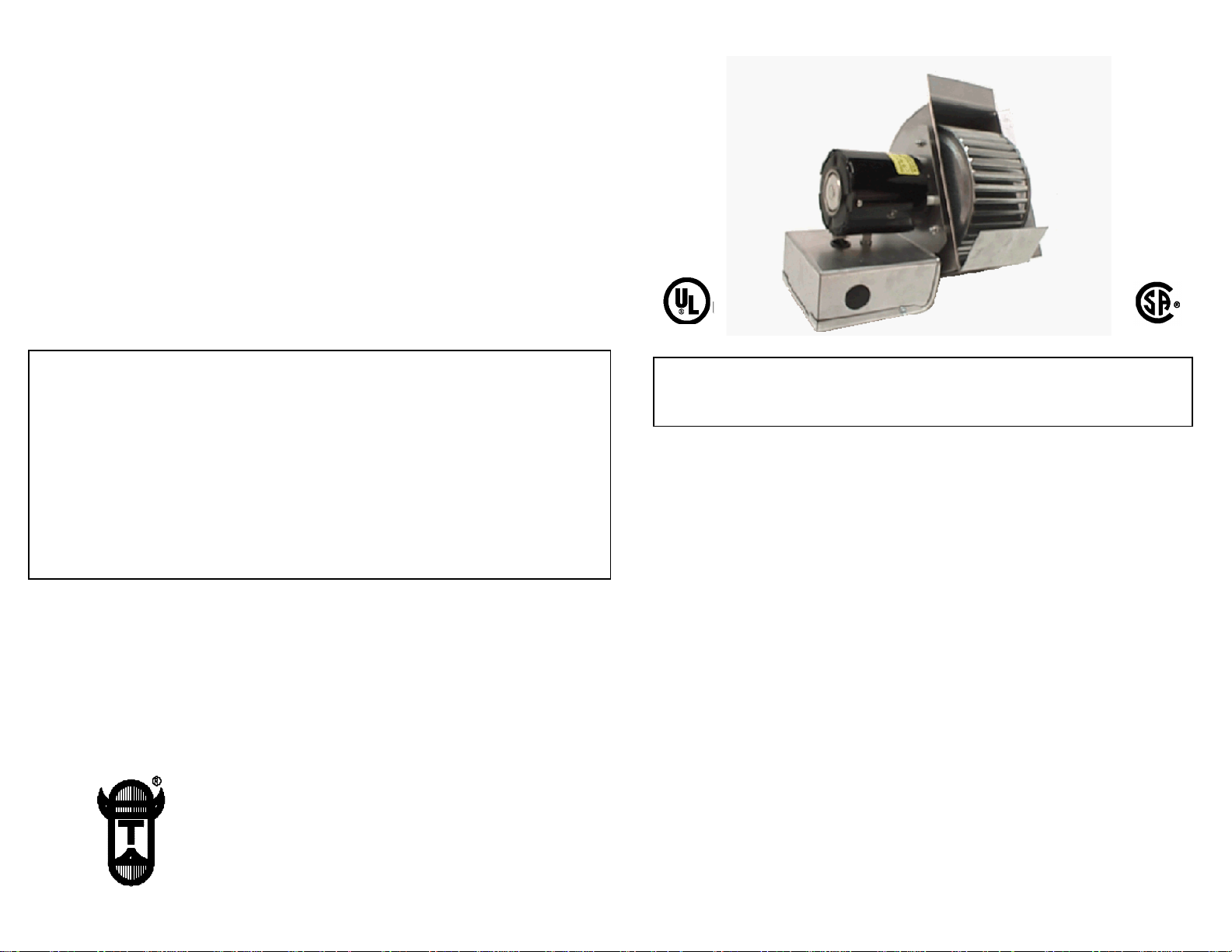
DUCT BOOSTER
®
MODEL DB-2
maintained no cleaning of the DUCT BOOSTER® blower wheel should be required.
If installed on a gravity warm air heating system which does not include filters, the DUCT
BOOSTER® should be removed from the duct and cleaned at the start of each heating
season. The motor is permanently lubricated so no oiling is necessary. The DUCT
BOOSTER® motor normally runs hot to the touch.
LIMITED PARTS WARRANTY
Tjernlund Products, Inc. warrants the components of its products for one year from date
of installation. This warranty covers defects in material and workmanship. This warranty
does not cover normal maintenance, transportation or installation charges for replacement parts or any other service calls or repairs. Products that are tampered with, dam aged, installed improperly, wired incorrectly or defective due to malfunctioning appliances
are not covered under this warranty. This warranty DOES NOT cover the complete
DUCT BOOSTER® if it is operable, except for the defective part.
TJERNLUND LIMITED ONE YEAR WARRANTY
Tjernlund Products, Inc. warrants to the original purchaser of this product that the product will be free from defects due
to faulty material or workmanship for a period of (1) year from the date of original purchase or delivery to the original
purchaser, whichever is earlier. Remedies under this warranty are limited to repairing or replacing, at our option, any
product which shall, within the above stated warranty period, be returned to Tjernlund Products, Inc. at the address listed below, postage prepaid. THERE ARE NO WARRANTIES WHICH EXTEND BEYOND THE DESCRIPTION ON THE
FACE HEREOF, AND TJERNLUND PRODUCTS, INC. EXPRESSLY DISCLAIMS LIABILITY FOR INCIDENTAL OR
CONSEQUENTIAL DAMAGES ARISING FROM THE USE OF THIS PRODUCT. THIS WARRANTY IS IN LIEU OF ALL
OTHER EXPRESS WARRANTIES AND NO AGENT IS AUTHORIZED TO ASSUME FOR US ANY LIABILITY ADDITIONAL TO THOSE SET FORTH IN THIS LIMITED WARRANTY. IMPLIED WARRANTIES ARE LIMITED TO THE
STATED DURATION OF THIS LIMITED WARRANTY. Some states do not allow limitation on how long an implied warranty lasts, so that limitation may not apply to you. In addition, some states do not allow the exclusion or limitation of
incidental or consequential damages, so that above limitation or exclusion may not apply to you. This warranty gives
you specific legal rights and you may also have other rights which may vary from State to State. Send all inquiries
regarding warranty work to Tjernlund Products, Inc. 1601 9th Street, White Bear Lake, MN 55110-6794. Phone (651)
426-2993 • (800) 255-4208 • Fax (651) 426-9547 or email us at fanmail@tjfans.com.
DB-2 REPLACEMENT PARTS LIST
MOTOR KIT 950-7025
WHEEL KIT 950-7010
HOUSING KIT 950-7000
TJERNLUND PRODUCTS, INC.
1601 Ninth Street • White Bear Lake, MN 55110-6794
PHONE (800) 255-4208 • (651) 426-2993 • FAX (651) 426-9547
Visit our web site • www.tjernlund.com
COPYRIGHT © 2000 TJERNLUND PRODUCTS, INC. P/N 8504030 REV. B 09/00
OWNERS INSTRUCTIONS
THESE INSTRUCTIONS MUST REMAIN WITH EQUIPMENT.
DO NOT DESTROY.
DESCRIPTION
The DB-2 DUCT BOOSTER® is designed to increase the flow of heated air in warm air
heating systems, or cooled air in central air conditioning systems.
Its size and design limits its use to branch ducts serving individual rooms, not the main
supply or “truck line” duct. The DUCT BOOSTER® can be mounted on round or flat
ducts. It is frequently installed on a warm air duct of a gravity warm air furnace to
provide heating for a basement area.
SPECIFICATIONS
Motor: 120/1/60, 1550 RPM, 40 watts, .52 FLA
GENERAL INFORMATION
NOTE: Under normal operating conditions the motor casing of the DUCTBOOSTER®
will feel hot to the touch. The motor has been designed to run at this temperature and is
Recognized by Underwriters Laboratories (UL), This normal operating temperature will
not harm the motor provided the operation and maintenance instructions enclosed with
each unit are followed.
These units have been factory tested and rated in accordance with AMCA standard 210,
test code for air moving devices.
Each DB-2 is electrically factory line tested before shipment.
After opening carton, inspect thoroughly for hidden damage. Fan wheel should rotate
freely. If any damage is found, notify freight carrier and your distributor immediately and
file a concealed damage claim.
Page 2
INSTALLATION (Tools Required)
1.
Opening should be cut in the bottom or top of a horizontal duct or any side of
DRILL 1/4” NUT RUNNER
5/16” DRILL BIT 1/4” WRENCH
SCREW DRIVER TIN SNIPS
NOTE: If installing the DUCT BOOSTER® on a flat duct, the housing
flanges will have to be bent at a 90Oangle before inserting DUCT
BOOSTER® into duct. This will allow screws to better align with the
speed clips provided.
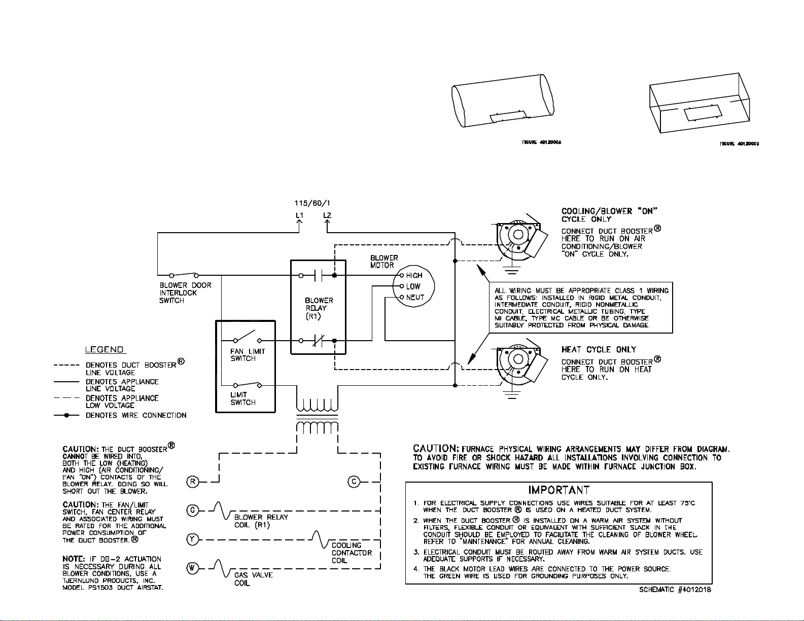
WIRING DUCT BOOSTER®IN PARALLEL WITH HEAT CYCLE
OR COOLING/BLOWER “ON” CYCLE
a vertical duct. The motor shaft will then be in the horizontal position. Apply
the mounting template provided to the duct, cut opening and drill four 5/16”
holes noted on template.
Page 3

2. Attach speed clips to vent pipe and align with four holes drilled in step 1.
3. Insert DUCT BOOSTER
®
in the slot with the adjustable damper curved plate
above blower wheel pointing in the direction of air flow. The front flange goes
inside the duct and the side flanges go on the outside. Bend the flanges to
conform to the duct. Secure DUCT BOOSTER® to duct utilizing speed clips
and screws provided. Use wrench to tighten nut behind electrical box.
INSTALLATION RESTRICTIONS
Do not install the DUCT BOOSTER® where temperatures of air within the duct
O
exceed 200
F. This temperature would only rarely be found on a forced warm
air system but could exist close to the furnace on a gravity warm air system.
Locating the DUCT BOOSTER® near the outlet end of a duct will provide the
most efficient performance.
The DUCT BOOSTER® must be installed with the motor shaft horizontal. It
can be installed on the bottom or top of a horizontal duct or any side of a
vertical duct.
CAUTIONS
1. Failure
to install, maintain and/or operate the DUCT BOOSTER® in accordance with manufacturer’s instructions may result in conditions which can
produce bodily injury and property damage.
2. Disconnect power supply when making wiring connections and servicing the
DUCT BOOSTER®. Failure to do so may result in personal injury and/or
equipment damage.
3. Make certain the power source is adequate for the DUCT BOOSTER®
requirements.
ADJUSTMENT OF VARI-DRAFT DAMPER
The DUCT BOOSTER® is shipped from the factory so that the maximum CFM
is established when unit is installed. To reduce the CFM, slide the Vari-Draft
damper so it will penetrate into duct further. Adjustments should be made prior
to installing the DUCT BOOSTER® into duct.
Page 4

OPERATION
The DUCT BOOSTER® can be operated and controlled in several manners:
1. By means of a standard ON/OFF switch.
2. By wiring the DUCT BOOSTER® in parallel with a gas or oil fired central furnace
blower motor.
3. By using the optional Tjernlund Products, Inc. Model PS1503 DUCT AIRSTAT pressure
switch, sold separately. The DUCT AIRSTAT will automatical ly control the operation of
the DUCT BOOSTER® in both heating and cooling systems. When the air handler
supplies warm or cool air, the DUCT AIRSTAT senses positive pressure and starts the
DUCT BOOSTER®.
ELECTRICAL WRING
NOTE: All wiring must be appropriate Class 1 wiring as follows: installed in rigid metal
conduit, intermediate conduit, rigid non-metallic conduit, electrical tubing, Type MI Cable,
Type MC Cable or be otherwise suitably protected from physical damage.
CAUTION: When wiring DUCT BOOSTER® in parallel to a gas or oil fired central furnace blower motor the following conditions must be fulfilled.
In addition, the DUCT BOOSTER® cannot be wired into both the low (heating) and high
(air conditioning/fan “on”) contacts of the blower relay. Doing so will short out the blower
motor.
A. The gas or oil-fired central furnace may include refrigerant cooling coils, however, it
must be equipped with 120 VAC single phase blower motors. The DUCT BOOSTER®
SHOULD NOT BE WIRED IN PARALLEL WITH 240 VAC BLOWER MOTORS.
B. The basic furnace wiring and components should not be disturbed except for wiring
interconnection of the DUCT BOOSTER® and furnace blower motor at a splice box in
the furnace.
C. The rating of furnace blower motor controller must be adequate to control blower
motor and the DUCT BOOSTER® motor. The DUCT BOOSTER® motor is rated 0.5
amps. NOTE: Blower motor controller should not be a variable speed tap type, solid
state speed control or any other type not suitable for dual motor control.
D. The existing short circuit and ground fault protection for the furnace blower motor
should be of a size and type which will adequately protect the DUCT BOOSTER®
motor. Refer to Section 430-53 of the National Electrical Code.
E. The wiring from the furnace to the DUCT BOOSTER® must be 14 AWG and the
furnace should be protected by over-current protection (fuses or circuit breakers) rated
at 15 amperes or less, (as applicable for 14 AWG conductors).
F. IMPORTANT: Refer to Section 430-53 (d) and Table 310-16 of the National Electrical
Code for additional limitations.
 Loading...