

Page 1
Copyright © 2013, Tjernlund Products, Inc. All rights reserved. P/N 8504201
8050049 03/05/13
TJERNLUND PRODUCTS, INC.
1601 Ninth Street • White Bear Lake, MN 55110-6794
PHONE (800) 255-4208 • (651) 426-2993 • FAX (651) 426-9547
Visit our web site • www.tjernlund.com
OWNER INSTRUCTIONS, DO NOT DESTROY.
SHUT OFF GAS SUPPLY BEFORE INSTALLING OR SERVICING THE CSA1.
FOR USE ON VERTICALLY TERMINATED CHIMNEYS ONLY.
NOTE: FLUE GAS TEMPERATURES MUST NOT EXCEED 575oF
(301
o
C) AT DRAFT INDUCER INLET. DRAFT INDUCERS
MUST NOT BE USED FOR SIDEWALL TERMINATED VENT
APPLICATIONS.
THESE INSTRUCTIONS ARE INTENDED AS AN AID TO QUALIFIED, LICENSED
SERVICE PERSONNEL FOR PROPER INSTALLATION, ADJUSTMENT AND
OPERATION OF THIS UNIT. READ THESE INSTRUCTIONS THOROUGHLY
BEFORE ATTEMPTING INSTALLATION OR OPERATION. FAILURE TO FOLLOW
THESE INSTRUCTIONS MAY RESULT IN IMPROPER INSTALLATION, ADJUSTMENT, SERVICE OR MAINTENANCE POSSIBLY RESULTING IN FIRE, ELECTRICAL SHOCK, CARBON MONOXIDE POISONING, EXPLOSION, PERSONAL
INJURY OR PROPERTY DAMAGE.
Model CSA1
Chimney Stack Assist Kit
Page 2
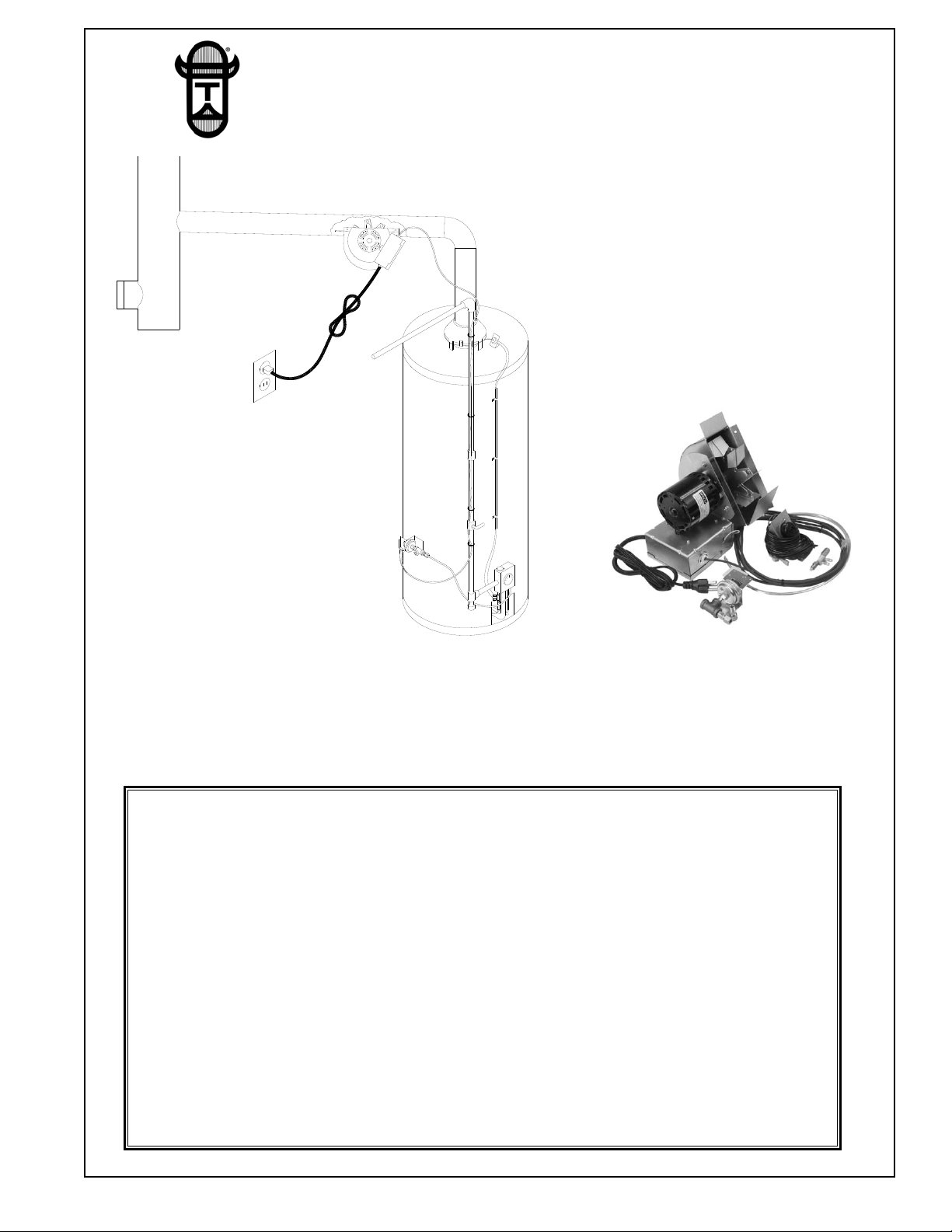
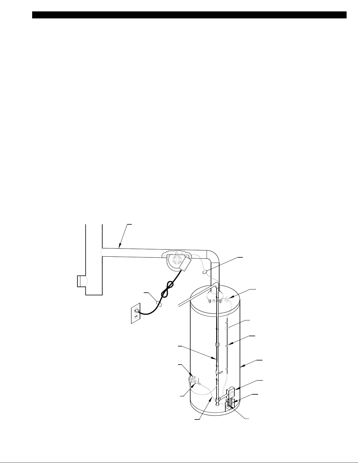
DESCRIPTION
The CSA1 Inducer assures draft in orpaned water heaters, oversized chimneys or when slight negative pressures in buildings prevent
proper exhaust of combustion gas. The venturi action of Tjernlund’s CSA1 Inducer starts air moving smoothly. These units are easy to
install and completely automatic in operation. Tjernlund’s unique design and durable construction makes them maintenance free.
IN THE EVENT OF PILOT OUTAGE
1. Push the reset button in the center of the Linear Limit Spillage Switch located
near the draft hood on the top of the water heater.
2. Follow water heater manufacturer’s re-lighting instructions attached to water
heater or located in water heater owner’s manual.
3. Turn the gas pilot knob at the top of water heater gas valve to “OFF” position.
WARNING: Gas pilot knob MUST REMAIN IN “OFF” POSITION FOR FIVE
MINUTES BEFORE PILOT IS RE-LIT. Perform steps 4 & 5 while waiting.
4. Visually verify that there is 115 volt power established to the CSA1.
Check fuse or circuit breaker, wall plug and electrical connections.
5. Visually verify that all electrical connections of control cord circuit are intact.
NOTE: Since the CSA1 cannot operate during a power outage, the safety interlock controls are designed to prohibit gas flow
to the water heater in the event of prolonged flue gas spillage. Follow the above procedures and water heater manufacturer’s instructions for relighting the pilot when power has been restored.
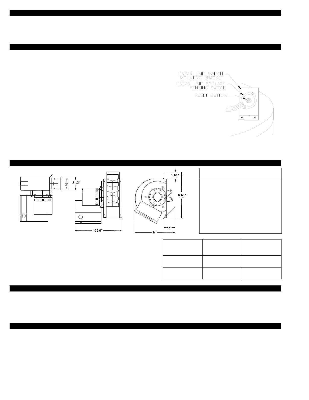
SPECIFICATIONS
Maximum BTU/hr. input rating of equipment: 65,000.
* NOTE: 3” 90 Degree elbows are equivalent to 3 feet.
4” 90 Degree elbows are equivalent to 4 feet.
TOOLS NEEDED
1/4” Nut Runner 11/32” Nut Runner Tin Snips Drill
Gas Pipe Tape High Temp Silicone 1/4” Tube/Pipe Cutter Drill Bit Set
7/16” Open End Wrench 3/8” Open End Wrench 1/2” Open End Wrench
SEQUENCE OF OPERATION
1. Water heater thermostat calls for heat.
2. CSA1 activates and the burner fires simultaneously.
3. Burner & CSA1 shut down simultaneously when thermostat is satisfied.
If sustained flue gas spillage is detected by the Linear Limit Spillage Switch the Water Heater Safety Circuit is opened and pilot light is
extinquished. The Linear Limit spillage switch must be reset and the pilot relit to reestablish burner operation.
1
MOTOR SPECIFICATIONS
ELECTRICAL DATA
Volts 115
Hertz 60
RPM 1550
Watts 35
Amps .43
Therm. Prot. Imp. Prot.
Pipe Diameter
Water Heater
Capacity
Max. Equivalent*
Horizontal Vent
Connector Length
3”
Up to
45,000 BTU/hr
15 feet
4”
Up to
65,000 BTU/hr
20 feet
Page 3
INSTALLATION RESTRICTIONS
WARNING
Failure to install, maintain and/or operate the CSA1 in accordance with manufacturer's instructions may result in conditions
which can produce bodily injury and property damage.
The CSA1 must be installed by a qualified installer in accordance with these instructions and all local codes or in their
absence in accordance with the latest editions of The National Fuel Gas Code (NFPA #54), Chimneys, Fireplaces, Vents, and
Solid Fuel Burning Appliances (NFPA 211), and the Occupational Safety and Health Act (OSHA) when applicable. Improper
installation can create a hazardous condition such as an explosion, fire, electrical shock or carbon monoxide poisoning
resulting in property damage, personal injury or death.
1. The CSA1 shall not be used on condensing heating equipment.
2. Gas-fired units without a draft hood / diverter must include a barometric draft regulator.
3. The CSA1 motor shaft must be mounted horizontally to prevent motor bearing wear.
4. The CSA1 shall not be installed where flue gas temperatures exceed 575
O
F (301°C) at the CSA1 inlet. Ambient room temperatures
must not exceed 104° F (40° C).
5. The installer must affix the wiring diagram label included with these instructions to the water heater casing adjacent to its rating plate.
6. The water heater may only be installed on the suction side of CSA1.
7. The installer must verify that the pilot safety controls on the water heater are in good operating condition before installation of the
water heater vent package.
8. The CSA1 must not be installed into any portion of a vent system which serves appliances other than the one vented by the CSA1.
9. Make certain the power source is adequate for the fan motor requirements. Do not add the CSA1 to a circuit where the total load is
unknown.
10. The installer must verify that the BTU/hr input of the water heater does not exceed the maximum input rating of the CSA1 (65,000 BTU/hr).
11. A safety inspection of the water heater must be performed before installation of the CSA1 as outlined in the International Fuel Gas
Code, (IFGC) Appendix D.
2
WITH THE ECO OF THE WATER HEATER.
REQUIRED. WIRE THE LINEAR LIMIT IN SERIES
THE THERMOCOUPLE JUNCTION ADAPTER IS NOT
ON 750 MILLIVOLT (POWER PILE) HEATERS
THERMOCOUPLE JUNCTION ADAPTER
PRESSURE TAP
FROM THERMOSTAT
6' LINEAR
LIMIT LEADS
115/1/60
SWITCH
GAS PRESSURE
GAS PRESSURE SWITCH
ALUMINUM TUBING TO
24" LONG 1/4" O.D.
LINE
GAS SUPPLY
BY OTHERS
WATER HEATER
BY OTHERS
THERMOSTAT
LINE
GAS PILOT
8050049 04/18/13
CLIPS
ROUTING
CABLE
THERMOSTAT CABLE
2 WIRE JACKETED
POWER CORD
SWITCH SET AT 185°F
SPILLAGE SENSING
LINEAR LIMIT
NEW GAS PRESSURE
TAP PORT LOCATION
NOTE:
CSA1
CAP ANY UNUSED
1/4 INCH PER FOOT
TOWARDS CHIMNEY
SLOPE UPWARD
- KEEP AWAY FROM
THE HOT FLUE PIPE
STACK OPENINGS
6 FOOT
Page 4

3
WITH THE ECO OF THE WATER HEATER.
REQUIRED. WIRE THE LINEAR LIMIT IN SERIES
THE THERMOCOUPLE JUNCTION ADAPTER IS NOT
ON 750 MILLIVOLT (POWER PILE) HEATERS
THERMOCOUPLE JUNCTION ADAPTER
PRESSURE TAP
FROM THERMOSTAT
6' LINEAR
LIMIT LEADS
115/1/60
NAMEPLATE
MOTOR
VENTER
POWER
SWITCH
GAS PRESSURE
GAS PRESSURE SWITCH
ALUMINUM TUBING TO
24" LONG 1/4" O.D.
LINE
GAS SUPPLY
BY OTHERS
WATER HEATER
BY OTHERS
THERMOSTAT
LINE
GAS PILOT
8050013 11/30/11
CLIPS
ROUTING
CABLE
THERMOSTAT CABLE
2 WIRE JACKETED
POWER
6 FOOT
BY OTHERS
FLUE PIPE
SWITCH SET AT 185°F
SPILLAGE SENSING
LINEAR LIMIT
GAS PRESSURE
TAP PORT
NOTE:
CORD
TJERNLUND
VENT HOOD
ACTUATION AND SAFETY CONTROLS INSTALLATION
After opening carton, inspect thoroughly for hidden damage. Fan blade should rotate freely. If any damage is found notify freight carrier and your distributor immediately and file a concealed damage claim.
Remove the hardware packet and Safety Controls.
GAS PRESSURE SWITCH INSTALLATION
IMPORTANT: Mount gas pressure switch so that diaphragm is in a VERTICAL
position, (See Diagram A).
The gas pressure switch is mounted on the casing of the water heater adjacent to the heater's thermostat/gas control valve. It should
be mounted close enough so that the supplied 1/4" tubing will reach from the gas pressure switch fitting to the thermostat/gas valve
pressure gauge port. The two provided screws are self-tapping and drilling. The screws do not require the use of a drill and their 1/2"
length assures that the inner tank will not be penetrated.
1. Adjust thermostat to “Off” and shut off gas to the water heater.
2. Mount the gas pressure switch by securing it to the heater casing with a screw in each of the two mounting holes.
IMPORTANT: Mount gas pressure switch so that diaphragm is in a VERTICAL
position, (See Diagram A).
3. Install the 1/8-NPT black pipe tee to the gas pressure switch, (See Diagram A). Use thread sealant, do not over
tighten. CAUTION: Utilize the hex nut on the gas pressure switch when attaching the black pipe tee.
4. Install the supplied Brass 1/8-NPT male x ¼" compression fitting to the 1/8-NPT black pipe tee, (See Diagram A). Use thread
sealant, do not over tighten.
5. Remove the PRESSURE TAP plug from the underside of the thermostat/gas control valve and install the supplied Brass
1/8-NPT male x ¼" compression fitting, (See Diagram A). Use thread sealant, do not over tighten.
IMPORTANT: DO NOT alter the heater's PILOT GAS LINE, (See Diagram A).
6. Use plug removed in step 5 and plug new pressure tap port in tee. Use thread sealant, do not over tighten.
7. Using a tube cutter, cut the appropriate length of the supplied 1/4" tubing to reach from the gas pressure switch fitting to the
PRESSURE TAP fitting of the thermostat/gas control valve. Make sure each end of the tubing is not pinched closed.
8. Use the 1/4" tubing to connect gas pressure switch fitting to the PRESSURE TAP PORT fitting on the thermostat/gas control valve.
9. Conduct a gas leakage test of all connections as outlined in the latest edition of NFPA 54, ANSI Z223.1, part 4 or local codes.
NOTE: A "gauge pressure tap port" can be accessed by removing the 1/8-NPT pipe plug that is on the 1/8-NPT black pipe tee
(attached to the gas pressure switch).
DO NOT ALTER
GAS SUPPLY
INTO PRESSURE TAP PORT.
GAS PRESSURE SWITCH
GAS CONTROL VALVE
THERMOSTAT/
PILOT GAS LINE
8050011 11/30/11
INSTALL BRASS 1/8-NPT MALE
x 1/4" COMPRESSION FITTING
THERMOCOUPLE
BURNER GAS LINE
COMMON
MUST BE MOUNTED VERTICALLY.
GAS PRESSURE SWITCH DIAPHRAGM
IMPORTANT:
BRASS 1/8-NPT MALE x 1/4"
COMPRESSION FITTING
THERMOSTAT / GAS CONTROL
TO PRESSURE TAP FITTING OF
1/4" OUTSIDE DIAMETER
ALUMINUM TUBING - CONNECT
VALVE.
1/8-NPT BLACK PIPE TEE
1/8-NPT PIPE PLUG - NEW
PRESSURE TAP PORT
NORMALLY OPEN
MOUNTING HOLES
IMPORTANT:
A
R
H
O
T
W
A
M
V
C
A
T
I
O
N
GAS
VALVE
DIAGRAM A
REMOVE 1/8 NPT PRESSURE TAP
Page 5

4
LINEAR LIMIT SPILLAGE SENSING SWITCH INSTALLATION
PURPOSE: To provide a means for appliance shut-down in the
event of flue blockage or CSA1 failure.
OPERATION: When concentrated spillage of the products of
combustion occurs from the draft hood, the Linear Limit Spillage
Switch circuit will open preventing burner operation.
1. Attach the Linear Limit sensing switch mounting bracket to the
top of the water heater using the 1/2” sheet metal screws
provided. The Linear Limit bracket should be approximately
1/2” from the draft hood.
2. Attach the three Linear Limit capillary mounting brackets
around the draft hood, equally spaced. Uses 3/8” screws.
3. Insert the Linear Limit spillage sensing switch capillary into
the “U” of the Linear Limit brackets outlining the perimeter of
the draft hood. The Linear Limit capillary may be overlapped.
if necessary, (See Diagram B). IMPORTANT: DO NOT CUT
THE CAPILLARY, it will be destroyed and water heater will be disabled.
4. Route the Linear Limit spillage sensing switch cable down the water heater casing locating the end near the Thermocouple or
E.C.O. of water heater. Secure it with the cable clamps and self drilling screws provided.
THERMOCOUPLE INSTALLATION
Unscrew the thermocouple from gas valve and screw in the Thermocouple Junction
Adapter. Screw the thermocouple into the Thermocouple Junction Adapter. Connect the
Linear Limit cables to the spade connections on the Thermocouple Junction Adapter, (See
Diagram C). NOTE: On 750 Millivolt (power pile) heaters, wire the Linear Limit Spill Switch
in series with the high limit (E.C.O.) of heater, see Thermopile installation below.
THERMOPILE INSTALLATION
Cut white wire from the thermopile gas valve and wire nut both ends with Linear Limit wires
(See Diagram D). Thermocouple Junction Adapter is not required for Thermopile installations.
T
O
H
N
O
I
T
A
C
A
V
M
R
A
W
JUNCTION ADAPTER
THERMOCOUPLE
950-0470 (JA1)
LINEAR LIMIT
SPILL SWITCH
GAS
VALVE
THERMOCOUPLE
8050010 11/30/11
DIAGRAM C
DIAGRAM B
DIAGRAM D
Page 6

FAN MOUNTING
WARNING: The CSA1 must not be used in side wall vent terminated applications. Side wall venting requires the use of a
Tjernlund Side wall Power Venter (Model VP-2F or VP-3F). CSA1 housing is single wall material. Six inch clearance must be
maintained to combustible materials.
1. The CSA1 may be mounted on vertical, horizontal, or inclined vent connectors. If used on a horizontal or inclined vent connector,
mount CSA1 on bottom of pipe, not on top, to avoid creating a heat trap in the inducer which could overheat the motor. The motor
shaft must be level and horizontal to avoid excessive bearing wear.
2. Select a position between the draft hood, draft diverter or barometric damper and the chimney or stack where there is at least 2
pipe diameters distance from either end of the fan and elbows or tees.
3. Cut a rectangular slot in the pipe using the template provided. Fasten the CSA1 in place with the provided speed clips and screws.
4. The front flange of the fan fits inside the vent pipe cut out and should point toward the chimney. Seal any opening around the CSA1
and vent pipe cutout with RTV high temperature silicone sealant.
ELECTRICAL
Route the control cable supplied with the CSA1 back to the water heater controls along the ceiling joists, taking care not to come closer than 6” to the vent pipe or any other potentially hot surface. In most cases, the gas supply line may be used as a routing path from
the ceiling to the Gas Pressure Switch, the supplied nylon straps may be used to secure the cable.
NOTE: If the distance between the CSA1 and the Gas Pressure Switch is greater than the length of the cable supplied, splice a section of 2 conductor PVC sheathed, 105 degree C thermostat cable to the supplied cable. An NEC approved accessible junction box
must be used to contain the splice. Splices shall be made mechanically secure and insulated with tape or fixture type splicing connectors may be employed. Strain relief hardware contained within the NEC approved junction box shall be utilized.
The CSA1 operates on 115 VAC, therefore a grounded outlet must be within reach of the six foot power cord supplied with CSA1. The
flexible power cord supplied with the unit may only be used where local codes permit. If local codes do not permit the use of flexible
power cord, follow steps below.
1. Remove the CSA1 electrical box cover, flexible cord and strain relief from the junction box.
2. Make “D” shaped hole CSA1 cord was removed from to a 7/8” diameter hole in CSA1 junction box.
3. Install suitable conduit fitting in enclosure and splice field wiring into existing wiring using code authorized method (wire nuts, etc.).
4. Replace electrical box cover.
ACTUATING AND SAFETY CONTROL CIRCUIT CONNECTIONS
1. If not previously completed, push both leads from the Linear Limit
Spill Switch onto Thermocouple Junction Adapter terminal, (See
Diagram C, Page 4). NOTE: On 750 Millivolt (power pile) heaters,
wire Linear Limit Spill Switch in series with high limit (E.C.O.) of heater,
(See Diagram D, Page 4).
2. Push the Red lead from CSA1 control cable onto the
common on the Gas Pressure Switch, (See Diagram E)
3. Push the Blue lead from the CSA1 control cable onto the
normally open terminal on the Gas Pressure Switch, (See Diag. E).
4. Plug the power cord from the CSA1 into a grounded 115 VAC outlet.
Verify that the outlet is powered through a 15 amp circuit breaker.
OPERATION CIRCUIT CHECK
1. Light the pilot following water heater manufacturer’s instructions and adjust appliance thermostat to call for heat.
2. The CSA1 fan should start and the water heater burner should ignite.
3. Adjust the appliance thermostat so that no heat is required. At this point the CSA1 and burner should shut off. The Thermocouple
Circuit has been verified.
WARNING: DO NOT OPERATE THE WATER HEATER WITHOUT THE LINEAR LIMIT WIRED INTO THE
THERMOCOUPLE JUNCTION ADAPTOR OR THERMOPILE ECO WATER HEATER SAFETY CIRCUIT.
5
BLUE WIRE FROM
CSA1 CONTROL CABLE
RED WIRE FROM
GAS PRESSURE
SWITCH
CSA1 CONTROL CABLE
8050050 4/18/13
NOTE: The installer must ensure that
all electrical connections are tight.
DIAGRAM E
Page 7

SAFETY INTERLOCK TEST
IMPORTANT:
The Linear Limit Spillage Switch must disable the heater in the event of a venting malfunction. The following procedure is necessary to
confirm that the heater is disabled in the event of a venting malfunction that would cause the Linear Limit to trip and open its circuit.
1. Remove a Linear Limit Switch lead (black wire) from Thermocouple Junction Adapter or Thermopile ECO and verify the heater
pilot is extinguished.
2. Reconnect Linear Limit Switch lead removed in step 1 and re-light pilot following the water heater manufacturer’s instructions.
CSA1 WATER HEATER STACK ASSIST KIT LADDER WIRING DIAGRAM
DRAFT AND COMBUSTION AIR TEST
WARNING:
The Linear Limit Spillage Switch is designed to alert the user to a potentially hazardous condition. It is not designed to and
cannot replace regular vent system inspection, appliance servicing and combustion testing. DO NOT USE IT AS A SUBSTITUTE FOR PROFESSIONAL APPLIANCE MAINTENANCE.
1. Close all doors and windows of the building. If the appliance is installed in a utility room or closet, close the entrance door. Close fire
place dampers.
2. Turn on clothes dryer. Turn on all exhaust fans, such as range hoods, bathroom exhaust and whole house fans to maximum speeds.
3. Following the water heater manufacturer’s instructions, place the appliance in operation, set thermostat for continuous operation.
4. Allow fans and appliance to operate for 5 minutes.
6
WHITEBLACK
WHITEBLACK
MOTOR
R1 RELAY
115 / 1 / 60 PLUG
YELLOWRED
RED
BLUE
TRANSFORMER
115V
24V
THERMOCOUPLE
PRESSURE
SWITCH
GAS
JUNCTION ADAPTER
BLACK BLACKBLACK
LINEAR LIMIT
SPILLAGE SENSING SWITCH
(185°F MANUAL RESET)
COM N / O
OR ECO OF WATER
HEATER
BLACK
78
R1 RELAY
TJERNLUND CSA1 (CHIMNEY STACK ASSIST)
ATTACH DIAGRAM ADJACENT TO WATER HEATER NAMEPLATE
1303310
BLACK
04/18/13
FIGURE 8075003
GREEN
DRAFT INDUCER
BLACK WHITE
24V LOW VOLTAGE FACTORY WIRING
115V LINE VOLTAGE FACTORY WIRING
DENOTES HEATING APPLIANCE MILLIVOLT
CIRCUIT (THERMOCOUPLE OR ECO)
LEGEND:
DENOTES A QUICK CONNECT
DENOTES A WIRE NUT
64
GREEN
Page 8

5. Tripping of the Linear Limit Spillage Switch during the 5 minutes indicates an unsafe operating condition. Turn off fuel supply to
appliance and DO NOT OPERATE UNTIL UNSAFE VENTING CONDITION IS INVESTIGATED BY A PROFESSIONAL
CONTRACTOR OR UTILITY SERVICE PERSONNEL.
NOTE:
In rare cases the Linear Limit may trip the control circuit on this vent system due to excessive negative pressure in the dwelling, down
drafts, excessive water heater heat loss, etc. In these cases it may be necessary to add a Post Purge Timer Relay. This device will
operate the CSA1 after the water heater has shut off and purge the vent system of residual flue gases. Contact Tjernlund if a Post
Purge Timer Relay is desired.
6. Return all windows, doors and fans to their previous conditions of use.
7. Sign and date these instructions to verify that the Sign:
combustion air and safety interlock test have been
completed. These instructions must remain on premises. Date:
HOW TO OBTAIN SERVICE ASSISTANCE
1. If you have any questions about the CSA1 or if it requires adjustment, repair or routine maintenance, we suggest that you con-
tact your installer, plumbing contractor or service agency.
2. If you require technical information contact Tjernlund Products, Inc. at 1-800-255-4208.
When contacting Tjernlund Products, Inc., please have the following information available:
1. Model number: CSA1
2. Name and address of installer and service agency
3. Date of original installation and dates any service work was performed
4. Details of the problem
LIMITED PARTS WARRANTY AND CLAIM PROCEDURE
Tjernlund Products, Inc. warrants the components of its products for one year from date of installation. This warranty covers defects in
material and workmanship. This warranty does not cover normal maintenance, transportation or installation charges for replacement
parts or any other service calls or repairs. Products that are tampered with, damaged, installed improperly, wired incorrectly or defective due to malfunctioning appliances are not covered under this warranty. This warranty DOES NOT cover the complete CSA1 if it is
operable; only the defective part.
1.) If unable to determine faulty component, contact your Tjernlund distributor or Tjernlund Products Technical Customer Service
Department at 1-800-255-4208 for troubleshooting assistance.
2.) After the faulty component is determined, return it to your Tjernlund distributor for replacement. Please include the job code
component was taken from. The job code is located on the Electrical Box coverplate. If the date code is older than 1 year, you
will need to provide a copy of the original installation receipt to your distributor. Credit or replacement will only be issued to a
Tjernlund distributor after the defective part has been returned prepaid to Tjernlund and verified defective.
7
TJERNLUND LIMITED ONE YEAR WARRANTY
Tjernlund Products, Inc. warrants to the original purchaser of this product that the product will be free from defects due to faulty material or workmanship for a period of (1)
year from the date of original purchase or delivery to the original purchaser, whichever is earlier. Remedies under this warranty are limited to repairing or replacing, at our
option, any product which shall, within the above stated warranty period, be returned to Tjernlund Products, Inc. at the address listed below, postage prepaid. THERE ARE
NO WARRANTIES WHICH EXTEND BEYOND THE DESCRIPTION ON THE FACE HEREOF, AND TJERNLUND PRODUCTS, INC. EXPRESSLY DISCLAIMS LIABILITY
FOR INCIDENTAL OR CONSEQUENTIAL DAMAGES ARISING FROM THE USE OF THIS PRODUCT. THIS WARRANTY IS IN LIEU OF ALL OTHER EXPRESS WARRANTIES AND NO AGENT IS AUTHORIZED TO ASSUME FOR US ANY LIABILITY ADDITIONAL TO THOSE SET FORTH IN THIS LIMITED WARRANTY. IMPLIED WARRANTIES ARE LIMITED TO THE STATED DURATION OF THIS LIMITED WARRANTY. Some states do not allow limitation on how long an implied warranty lasts, so that
limitation may not apply to you. In addition, some states do not allow the exclusion or limitation of incidental or consequential damages, so that above limitation or exclusion may not apply to you. This warranty gives you specific legal rights and you may also have other rights which may vary from State to State. Send all inquiries regarding warranty work to Tjernlund Products, Inc. 1601 9th Street, White Bear Lake, MN 55110-6794. Phone (651) 426-2993 • (800) 255-4208 • Fax (651) 426-9547 • Email:
fanmail@tjfans.com
REPLACEMENT PARTS LIST
ITEM PART NUMBER ITEM PART NUMBER
Gas Pressure Switch 950-2080 Motor Kit 950-3020
24V Transformer 950-2030 Linear Limit Spill Switch 950-2064
Wheel Kit 950-3010 Thermocouple Junction Adapter 950-0470
Relay Kit 950-1040 Housing Kit 950-3000
 Loading...