

TP04600
Date 01-08
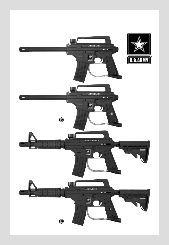
ALPHA BLACK
TM
MARKERTMLINE
TM
• Owner’s Manual
• Manual del Usuario
PLAY..
SMART...
PLAY..
STRONG...
ARMY..
STRONG
SMM
.
★alpha black★
BASIC
★alpha black★
BASIC
E-TRIGGER
TM
★alpha black★
TACTICAL
EDITION
★alpha black★
TACTICAL
EDITION
E-TRIGGER
TM
TM
TM
TM
TM
WARNING
THIS IS NOT A TOY. MISUSE MAY CAUSE SERIOUS
INJURY OR DEATH. EYE, FACE AND EAR PROTECTION
DESIGNED FOR PAINTBALL MUST BE WORN BY THE
USER AND ANY PERSON WITHIN RANGE. WE
RECOMMEND AT LEAST 18 YEARS OLD TO PURCHASE.
PERSONS UNDER 18 MUST HAVE ADULT SUPERVISION
WHEN USING THIS PRODUCT. READ THE OWNER’S
MANUAL BEFORE USING THIS PRODUCT.
E
N
G
L
I
S
H
E
N
G
L
I
S
H
ADVERTENCIA
ESTO NO ES UN JUGUETE. UN USO INAPROPIADO
PUEDE CAUSAR SERIAS HERIDAS O LA MUERTE.
OJOS, CARA Y OIDOS DEBEN SER PROTEGIDOS TODO
EL TIEMPO, CON LA PROTECCIÓN DISEÑADA PARA
PAINTBALL TANTO PARA JUGADORES COMO PARA
CUALQUIER PERSONA QUE ESTE EN EL RADIO DE
ALCANCE. RECOMENDAMOS AL MENOS 18 AÑOS
PARA LA COMPRA Y USO. LAS PERSONAS MENORES
DE 18 AÑOS DEBEN USAR ESTE PRODUCTO BAJO LA
SUPERVISIÓN DE UN ADULTO. ANTES DE USAR ESTE
PRODUCTO LEA EL MANUAL DEL USUARIO.
E
S
P
A
Ñ
O
L
E
S
P
A
Ñ
O
L
WARNING
SAFETY IS YOUR RESPONSIBILITY
ALWAYS KEEP
TRIGGER SAFETY
IN SAFE MODE
UNLESS FIRING
AS DETAILED IN
INSTRUCTIONS
ON PAGE 4.
ALWAYS KEEP
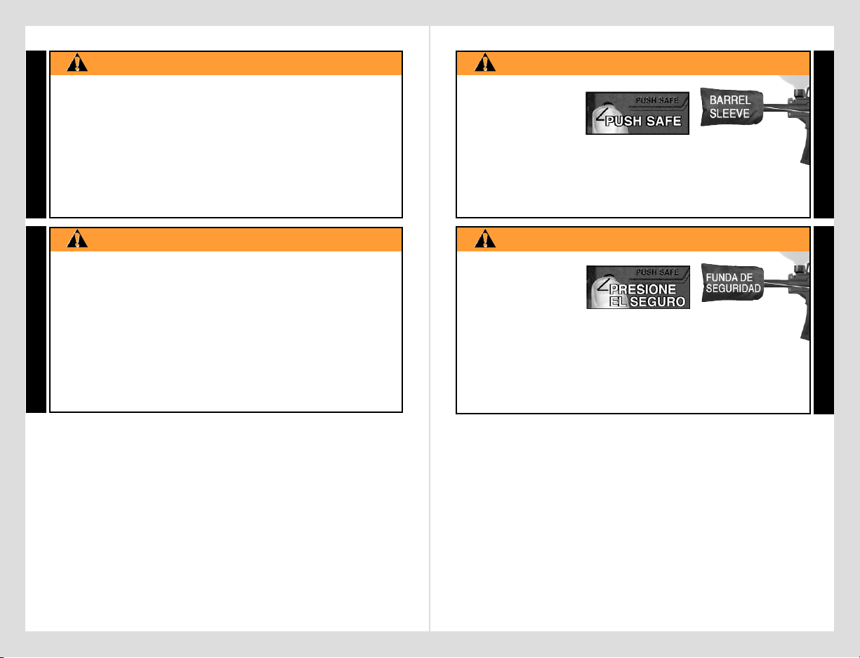
BARREL SLEEVE
INSTALLED WHEN
NOT IN SHOOTING
SITUATION AS
DETAILED IN
INSTRUCTIONS
ON PAGE 2.
READ, FAMILIARIZE
YOURSELF AND ANY
OTHER USER OF THIS
MARKER WITH THE
SAFETY INSTRUCTIONS
IN THIS MANUAL.
FOLLOW THESE
INSTRUCTIONS WHEN
USING, WORKING ON,
TRANSPORTING OR
STORING THIS MARKER.
ADVERTENCIA
LA SEGURIDAD ES SU RESPONSABILIDAD
MANTENGA SIEMPRE
EL SEGURO DEL
GATILLO ACTIVADO
A MENOS QUE SEA
NECESARIO HACER
DISPAROS.
COMO
SE VE EN LAS
INSTRUCCIONES
DE LA PÁGINA 3.
MANTENGA
LA FUNDA
DE
SEGURIDAD
INSTALADA
CUANDO NO
ESTE
HACIENDO
DISPAROS
COMO SE
ILUSTRA EN
LA PÁGINA 1.
EL PROPIETARIO Y
TODA PERSONA QUE
VA A USAR ESTE
MARCADOR DEBE LEER Y
FAMILIARIZARCE
CON
LAS INSTRUCCIONES DE
SEGURIDAD EN ESTE
MANUAL. SIGA LAS
INSTRUCCIONES DE
USO, MANTENIMIENTO,
TRANSPORTE Y
ALMACENAJE DE
ESTE MARCADOR.
E
N
G
L
I
S
H
E
S
P
A
Ñ
O
L
WARNING
SAFETY IS YOUR RESPONSIBILITY
ALWAYS KEEP
TRIGGER SAFETY
IN SAFE MODE
UNLESS FIRING
AS DETAILED IN
INSTRUCTIONS
ON PAGE 4.
ALWAYS KEEP
BARREL SLEEVE
INSTALLED WHEN
NOT IN SHOOTING
SITUATION AS
DETAILED IN
INSTRUCTIONS
ON PAGE 2.
READ, FAMILIARIZE
YOURSELF AND ANY
OTHER USER OF THIS
MARKER WITH THE
SAFETY INSTRUCTIONS
IN THIS MANUAL.
FOLLOW THESE
INSTRUCTIONS WHEN
USING, WORKING ON,
TRANSPORTING OR
STORING THIS MARKER.
ADVERTENCIA
LA SEGURIDAD ES SU RESPONSABILIDAD
MANTENGA SIEMPRE
EL SEGURO DEL
GATILLO ACTIVADO
A MENOS QUE SEA
NECESARIO HACER
DISPAROS.
COMO
SE VE EN LAS
INSTRUCCIONES
DE LA PÁGINA 3.
MANTENGA
LA FUNDA
DE
SEGURIDAD
INSTALADA
CUANDO NO
ESTE
HACIENDO
DISPAROS
COMO SE
ILUSTRA EN
LA PÁGINA 1.
EL PROPIETARIO Y
TODA PERSONA QUE
VA A USAR ESTE
MARCADOR DEBE LEER Y
FAMILIARIZARCE
CON
LAS INSTRUCCIONES DE
SEGURIDAD EN ESTE
MANUAL. SIGA LAS
INSTRUCCIONES DE
USO, MANTENIMIENTO,
TRANSPORTE Y
ALMACENAJE DE
ESTE MARCADOR.
WARNING
CONGRATULATIONS on your purchase of a U.S. ARMY Alpha Black
TM
paintball marker. We believe our Alpha BlackTM line of markers to be the
most accurate and durable paintball markers available, and are proudly
manufactured by Tippmann
®
. All Alpha BlackTM line markers will give
many years of dependable service if cared for properly. Visit
www.usarmypaintball.com and find out how to maximize your paintball
experience – play smart... play strong...Army Strong
SM
.
Please take time to read this manual thoroughly and become familiar
with your Alpha Black
TM
model’s parts, operation, and safety precautions
before you attempt to load or fire this marker. If you have a missing or
broken part or need assistance, please contact Tippmann
®
Consumer
Relations at 1-800-533-4831 for fast friendly service.
TABLE OF CONTENTS
Warning/Caution .................................................................................... 2
Warning/Caution Barrel Sleeve Installation ......................................... 2
Warning/Liability Statement .................................................................. 4
Safety is your Responsibility / Familiarize Yourself With Safety ......... 4
Safe Mode = Turning The Safety On (PUSH SAFE) .......................... 4
Fire Mode = Turning The Safety Off (PUSH FIRE) ........................... 4
Getting Started ....................................................................................... 6
1. Prepare Marker for Air Supply Cylinder Installation .................... 6
2. Air Supply Cylinder Installation ..................................................... 7
3. Hopper Installation ........................................................................ 7
4. Rate of Fire Adjustments and Troubleshooting .......................... 8
5. Velocity Adjustment ........................................................................ 8
Specifications ........................................................................................ 11
Schematics ........................................................................................... 12
Unloading Your Marker ....................................................................... 14
Air Supply Cylinder Removal .............................................................. 14
Cleaning & Maintenance ..................................................................... 14
Repairing Air Supply Leaks ................................................................. 15
Storage ................................................................................................. 15
Marker Disassembly / Assembly ......................................................... 16
Warranty and Repair Policy ................................................................ 20
Warranty or Repair Procedure ........................................................... 20
Warranty Registration ......................................................................... 20
3
E
N
G
L
I
S
H
2
E
N
G
L
I
S
H
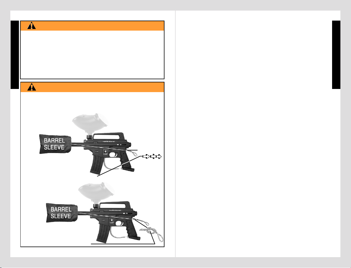
CORD
LENGTH
ADJUSTOR
BUTTON
• EXCEPT WHEN YOUR MARKER IS IN USE, ALWAYS MAKE
SURE THAT THE TRIGGER SAFETY IS IN SAFE MODE (SEE
INSTRUCTIONS ON PAGE 4), AND THE BARREL SLEEVE IS
PROPERLY INSTALLED ON YOUR MARKER AS SHOWN BELOW.
BARREL SLEEVE INSTALLATION
WARNING
THIS IS NOT A TOY. MISUSE MAY CAUSE SERIOUS
INJURY OR DEATH. EYE, FACE AND EAR PROTECTION
DESIGNED FOR PAINTBALL MUST BE WORN BY THE
USER AND ANY PERSON WITHIN RANGE. WE
RECOMMEND AT LEAST 18 YEARS OLD TO PURCHASE.
PERSONS UNDER 18 MUST HAVE ADULT SUPERVISION
WHEN USING THIS PRODUCT. READ THE OWNER’S
MANUAL BEFORE USING THIS PRODUCT.
4) AFTER CORD LENGTH IS
ADJUSTED, LOCK CORD
LENGTH BY TYING A KNOT IN
THE CORD AGAINST THE BACK
OF THE ADJUSTOR AS SHOWN.
2955 Adams Center Road, Fort Wayne, IN 46803 USA
P) 260-749-6022 • F) 260-749-6619 • www.tippmann.com • www.usarmypaintball.com
★alpha black★
1) SLIDE BARREL INTO SLEEVE AND LOOP CORD OVER TOP
OF RECEIVER AND POSITION AT BACK OF GRIP AS SHOWN
BELOW.
2) PINCH CORD LENGTH
ADJUSTOR BUTTON AND
HOLD TO BACK OF GRIP AS
YOU PULL CORD THROUGH IT UNTIL ADJUSTOR IS SNUG
AGAINST BACK OF GRIP, THEN RELEASE BUTTON.
3) CHECK TO BE SURE YOU LEAVE ENOUGH CORD
ELASTICITY TO PULL CORD/ADJUSTOR UP OVER TOP OF
MARKER TO REMOVE BARREL SLEEVE FOR FIRING.
CONGRATULATIONS on your purchase of a U.S. ARMY Alpha Black
TM
paintball marker. We believe our Alpha BlackTM line of markers to be the
most accurate and durable paintball markers available, and are proudly
manufactured by Tippmann
®
. All Alpha BlackTM line markers will give
many years of dependable service if cared for properly. Visit
www.usarmypaintball.com and find out how to maximize your paintball
experience – play smart... play strong...Army Strong
SM
.
Please take time to read this manual thoroughly and become familiar
with your Alpha Black
TM
model’s parts, operation, and safety precautions
before you attempt to load or fire this marker. If you have a missing or
broken part or need assistance, please contact Tippmann
®
Consumer
Relations at 1-800-533-4831 for fast friendly service.
TABLE OF CONTENTS
Warning/Caution .................................................................................... 2
Warning/Caution Barrel Sleeve Installation ......................................... 2
Warning/Liability Statement .................................................................. 4
Safety is your Responsibility / Familiarize Yourself With Safety ......... 4
Safe Mode = Turning The Safety On (PUSH SAFE) .......................... 4
Fire Mode = Turning The Safety Off (PUSH FIRE) ........................... 4
Getting Started ....................................................................................... 6
1. Prepare Marker for Air Supply Cylinder Installation .................... 6
2. Air Supply Cylinder Installation ..................................................... 7
3. Hopper Installation ........................................................................ 7
4. Rate of Fire Adjustments and Troubleshooting .......................... 8
5. Velocity Adjustment ........................................................................ 8
Specifications ........................................................................................ 11
Schematics ........................................................................................... 12
Unloading Your Marker ....................................................................... 14
Air Supply Cylinder Removal .............................................................. 14
Cleaning & Maintenance ..................................................................... 14
Repairing Air Supply Leaks ................................................................. 15
Storage ................................................................................................. 15
Marker Disassembly / Assembly ......................................................... 16
Warranty and Repair Policy ................................................................ 20
Warranty or Repair Procedure ........................................................... 20
Warranty Registration ......................................................................... 20
3
E
N
G
L
I
S
H
2955 Adams Center Road, Fort Wayne, IN 46803 USA
P) 260-749-6022 • F) 260-749-6619 • www.tippmann.com • www.usarmypaintball.com
★alpha black★
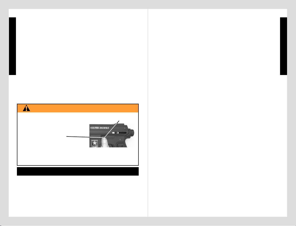
• EXCEPT WHEN YOUR MARKER
IS IN USE, ALWAYS MAKE
SURE THAT THE BARREL SLEEVE
IS INSTALLED (SEE PAGE 2) AND
THE TRIGGER SAFETY
IS IN SAFE MODE WHICH
DISABLES THE TRIGGER.
• TO TURN ON THE SAFETY (SAFE MODE): PUSH THE SAFETY
IN AS SHOWN ABOVE.
• TO TURN SAFETY OFF (FIRE MODE): PUSH SAME BUTTON
ON OPPOSITE SIDE OF RECEIVER.
5
Safety Is Your Responsibility (continued from page 4)
Safety Is Your Responsibility
(continued on page 6)
E
N
G
L
I
S
H
Warning/Liability Statement
This marker is classified as a dangerous weapon and is surrendered
by Tippmann Sports, LLC with the understanding that the purchaser
assumes all liability resulting from unsafe handling or any action that
constitutes a violation of any applicable laws or regulations. Tippmann
Sports, LLC shall not be liable for personal injury, loss of property or
life resulting from the use of this weapon under any circumstances,
including the intentional, reckless, negligent or accidental discharges.
All information contained in this manual is subject to change without
notice. Tippmann Sports, LLC reserves the right to make changes
and improvements to products without incurring any obligation to
incorporate such improvements in products previously sold.
If you as a user do not accept liability, Tippmann Sports, LLC requests
you do not use a Tippmann Sports, LLC marker. By using this
paintball marker you release Tippmann Sports, LLC of any and all
liability associated with its use.
4
SAFETY IS YOUR RESPONSIBILITY!
The ownership of this weapon places upon you the total responsibility
for its safe and lawful use. You must observe the same safety precautions
as you would any firearm to assure the safety of not only yourself but
everyone around you. The user should at all times use caution when
using this marker. The sport of Paintball will be viewed and judged upon
your safe and sportsmanlike conduct. Always remember that the game
of Paintball can only survive and grow if it remains SAFE!
Safety Is Your Responsibility
(continued on page 5)
E
N
G
L
I
S
H
WARNING
PUSH SAFE
TRIGGER SAFETY ACTIVATION
• Do not load or fire this marker until you have completely read this
manual and are familiar with its safety features, mechanical operation
and handling characteristics.
• Handle this and any marker as if it were loaded at all times.
• Keep your finger off the trigger until ready to shoot.
• Do not look down the barrel of a paintball marker. Accidental discharge
into the eyes may cause permanent injury or death.
• Keep the marker on safe until ready to shoot (see page 4).
• Keep the barrel sleeve installed on marker when not shooting.
• Never point the marker at anything you do not intend to shoot.
• Never fire your marker at anything you do not intend to shoot because
there may be balls or foreign debris lodged in the chamber, barrel
and / or the marker valve.
• Do not shoot at fragile objects such as windows.
• Never fire your marker at personal property of others, the paintball
can stain the paint of automobiles and houses.
• Always keep the muzzle pointed down or in a safe direction, even if
you stumble or fall.
• Eye, face and ear protection designed specifically to stop paintballs in
the form of goggles and full face mask meeting ASTM Specification F
1776 must be worn by the user and any person within range.
• Never shoot at a person who is not protected by eye, face and ear
protection designed for paintball.
• Pressurize and load the marker only when the marker will be
immediately used.
• NOTE: Before storing or disassembling be sure to remove paintballs
and air supply (see unloading and air supply removal instructions on
page 14). Install barrel sleeve (see page 2).
• Store the marker unloaded and degassed in a secure place.
• Do not field strip or otherwise disassemble this marker while it is
pressurized with air supply.
• Dress appropriately when playing the game of paintball. Avoid exposing
any skin when playing the game of paintball. Even a light layer will
absorb some of the impact and protect you from the paintballs.
• Keep exposed skin away from escaping gas when installing or removing
air supply cylinder or if the marker or air supply is leaking. Compressed
air, CO
2, and nitrogen gasses are very cold and can cause frostbite
under certain conditions.
• Use only .68 caliber paintballs, never load or fire any foreign objects.
FAMILIARIZE YOURSELF WITH SAFETY...
5
Safety Is Your Responsibility (continued from page 4)
Safety Is Your Responsibility
(continued on page 6)
E
N
G
L
I
S
H
• Do not load or fire this marker until you have completely read this
manual and are familiar with its safety features, mechanical operation
and handling characteristics.
• Handle this and any marker as if it were loaded at all times.
• Keep your finger off the trigger until ready to shoot.
• Do not look down the barrel of a paintball marker. Accidental discharge
into the eyes may cause permanent injury or death.
• Keep the marker on safe until ready to shoot (see page 4).
• Keep the barrel sleeve installed on marker when not shooting.
• Never point the marker at anything you do not intend to shoot.
• Never fire your marker at anything you do not intend to shoot because
there may be balls or foreign debris lodged in the chamber, barrel
and / or the marker valve.
• Do not shoot at fragile objects such as windows.
• Never fire your marker at personal property of others, the paintball
can stain the paint of automobiles and houses.
• Always keep the muzzle pointed down or in a safe direction, even if
you stumble or fall.
• Eye, face and ear protection designed specifically to stop paintballs in
the form of goggles and full face mask meeting ASTM Specification F
1776 must be worn by the user and any person within range.
• Never shoot at a person who is not protected by eye, face and ear
protection designed for paintball.
• Pressurize and load the marker only when the marker will be
immediately used.
• NOTE: Before storing or disassembling be sure to remove paintballs
and air supply (see unloading and air supply removal instructions on
page 14). Install barrel sleeve (see page 2).
• Store the marker unloaded and degassed in a secure place.
• Do not field strip or otherwise disassemble this marker while it is
pressurized with air supply.
• Dress appropriately when playing the game of paintball. Avoid exposing
any skin when playing the game of paintball. Even a light layer will
absorb some of the impact and protect you from the paintballs.
• Keep exposed skin away from escaping gas when installing or removing
air supply cylinder or if the marker or air supply is leaking. Compressed
air, CO
2, and nitrogen gasses are very cold and can cause frostbite
under certain conditions.
• Use only .68 caliber paintballs, never load or fire any foreign objects.

7
E
N
G
L
I
S
H
For Tactical Edition models: (continued from page 6)
6
Safety Is Your Responsibility (continued from page 5)
For Tactical Edition models:
(continued on page 7)
STEP 2) Air Supply Cylinder Installation
• Do not pressurize a partially assembled paintball marker.
• First install barrel sleeve (see instructions on page 2).
• Next put trigger safety in Safe Mode
(see instructions on page 4).
❏
Eye protection designed for paintball use must be worn by the user
and any person within range. Do not disassemble this marker while it is
pressurized with air. Do not pressurize a partially assembled marker.
• To install the air supply cylinder, lubricate the cylinder valve o-ring
with a little marker oil then insert the cylinder valve end into the air
supply adapter at the back end of the marker grip. Twist the cylinder
clockwise into the marker until it stops. Your marker is ready to
fire once you switch to Fire Mode from Safe Mode. If the tank is full
and you do not hear the air supply engage, the pin valve could be too
short or the pin valve seal is damaged.
• Next you need to cock the marker
by sliding the bolt handle all the
way back until it locks into place .
Always keep marker in the cocked
position when air supply is attached
to the marker. This will help prevent
an accidental discharge.
•
Install the shroud before you install the barrel . To install the
shroud:
❏ ❏
❏ ❏
❏
Remove receiver bolt and
❏ ❏
❏ ❏
❏
insert the shroud.
❏❏
❏❏
❏
Replace and tighten the bolt to hold the shroud in place.
•
Install the barrel (with the shroud installed): ❏ apply marker oil onto
the barrel o-ring
, insert the barrel into the shroud / receiver and
carefully screw it in
.
E
N
G
L
I
S
H
Read each step completely before performing the step:
NOTE: Carefully hand start all threaded parts and do not overtighten and
strip threaded parts when assembling.
❏❏
❏❏
❏
For Alpha BlackTM Basic models:
•
Install the barrel .❏ Apply marker oil onto the barrel o-ring ,
insert the barrel into the receiver and carefully screw it in
.
• Avoid alcoholic beverages before and during the use of this marker.
Handling markers while under the influence of drugs or alcohol is a
criminal disregard for public safety.
• Avoid shooting an opponent at point blank, 6 feet or less.
• Familiarize yourself with instructions listed on air supply cylinder or adaptor.
Contact the air supply cylinder or adaptor manufacturer with any questions.
• Always measure your marker’s velocity before playing paintball and
never shoot at velocities in excess of 300 feet per second (see
instructions on page 8).
STEP 1) Prepare Marker for Air Supply Cylinder Installation
• For Basic marker with E-Trigger
TM
- You must first read and follow
E-Trigger
TM
Operating Instructions (on pages 8 - 10) before
performing
STEP 2 on page 7.
• For Basic marker without E-Trigger
TM
go to STEP 2 on page 7.
• For Tactical Edition marker with E-Trigger
TM
- You must first read and
follow E-Trigger
TM
Operating Instructions (on pages 8-10) before
performing STEP 2.
• For Tactical Edition marker without E-Trigger
TM
go to STEP 2.
• For Alpha Black
TM
Tactical Edition models:
Squeeze the
adjustment lever
and slide to shorten
or to lengthen stock.
Shorten
Lengthen
Length
Adjustment:
• Install the collapsible stock.
❏❏
❏❏
❏
With the end cap cover removed (slides off).
❏❏
❏❏
❏
Slide stock up into end cap.
❏❏
❏❏
❏
Insert bolt and carefully tighten .
STEP 3) Hopper Installation
• Barrel Sleeve must be installed (see page 2) and safety in Safe Mode
(see page 4) before filling the hopper.
• Make sure that the feed elbow and hopper are clean and free of any
sharp edges to keep paintballs feeding into the marker smoothly.
• Install the hopper neck into the feed elbow of your marker and
tighten the hopper down with a 3/16” allen wrench included
with your marker.
NOTE: Do not overtighten or the elbow may break. With the barrel
Hopper Installation (continued on page 8)
GETTING STARTED
7
E
N
G
L
I
S
H
For Tactical Edition models: (continued from page 6)
STEP 2) Air Supply Cylinder Installation
• Do not pressurize a partially assembled paintball marker.
• First install barrel sleeve (see instructions on page 2).
• Next put trigger safety in Safe Mode
(see instructions on page 4).
• To install the air supply cylinder, lubricate the cylinder valve o-ring
with a little marker oil then insert the cylinder valve end into the air
supply adapter at the back end of the marker grip. Twist the cylinder
clockwise
into the marker until it stops. Your marker is ready to
fire once you switch to Fire Mode from Safe Mode. If the tank is full
and you do not hear the air supply engage, the pin valve could be too
short or the pin valve seal is damaged.
• Next you need to cock the marker
by sliding the bolt handle all the
way back until it locks into place
.
Always keep marker in the cocked
position when air supply is attached
to the marker. This will help prevent
an accidental discharge.
• For Tactical Edition marker with E-Trigger
TM
- You must first read and
follow E-Trigger
TM
Operating Instructions (on pages 8-10) before
performing
STEP 2.
• For Tactical Edition marker without E-Trigger
TM
go to STEP 2.
Squeeze the
adjustment lever
and slide to shorten
or to lengthen stock.
Shorten
Lengthen
Length
Adjustment:
STEP 3) Hopper Installation
• Barrel Sleeve must be installed (see page 2) and safety in Safe Mode
(see page 4) before filling the hopper.
• Make sure that the feed elbow and hopper are clean and free of any
sharp edges to keep paintballs feeding into the marker smoothly.
• Install the hopper neck into the feed elbow of your marker and
tighten the hopper down with a 3/16” allen wrench
included
with your marker.
NOTE: Do not overtighten or the elbow may break. With the barrel
Hopper Installation (continued on page 8)
Power
Button
LED
INSTALL THE AIR SUPPLY AND LOAD THE HOPPER WITH PAINTBALLS
ONLY AFTER YOU:
❏ ❏
❏ ❏
❏
HAVE THE BARREL SLEEVE INSTALLED (SEE PAGE 2) ;
❏ ❏
❏ ❏
❏
HAVE THE SAFETY IN THE "SAFE" POSITION ( SEE PAGE 4);
❏ ❏
❏ ❏
❏
HAVE SUCCESSFULLY INSTALLED THE BATTERY (STEP 2) AND
❏ ❏
❏ ❏
❏
ARE FAMILIAR WITH THE E-TRIGGERTM NORMAL OPERATION (STEP 3:).
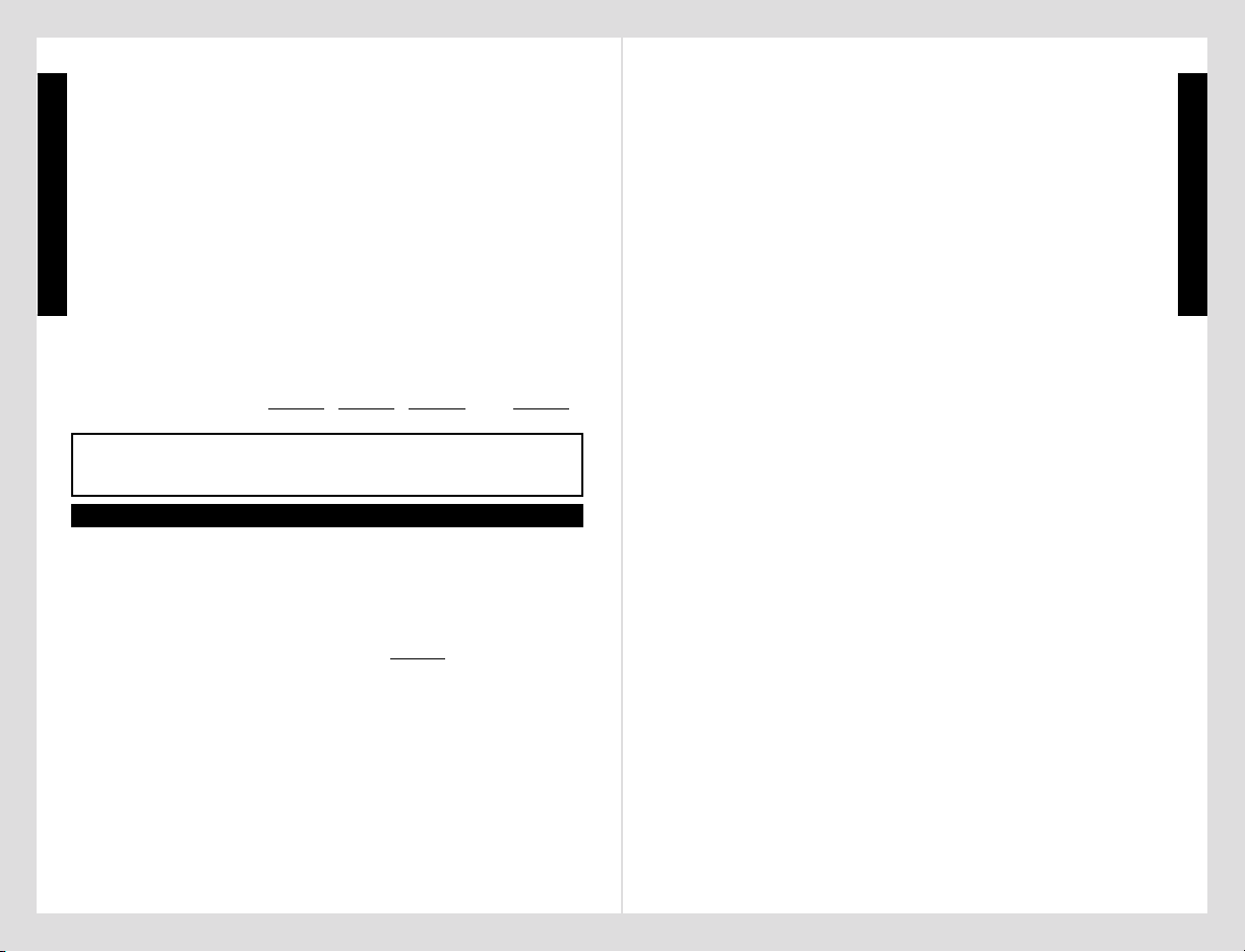
WARNING
READ EACH STEP COMPLETELY BEFORE PERFORMING THE STEP:
• Install new battery. ❏ Attach 9 volt battery to the
battery connector and be sure wires lay flat inside
the cutout area of receiver (as shown on page 19).
❏
Carefully tilt and insert your new battery, wire
attached end first, into receiver as shown .
❏
Reinstall left receiver grip with 2 grip bolts.
Battery installation is complete.
❏ ❏
❏ ❏
❏
1) To Turn ON the E-Trigger to normal operation - Ready To Fire:
Without holding the trigger: Use a small object
like an allen wrench to
❏
press and hold
the power button (for about 5 seconds) until
the green LED light comes on and then
release the power button.
❏
Your marker is now ready for normal operation
in the SEMI-AUTO Firing Mode: 1 pull of the trigger fires 1 time (This is
the Factory Default Firing Mode Setting).
NOTE: If pressing the power button failed to turn on the LED light, see
troubleshooting on page 10.
NOTE: The E-Trigger Low Battery Indicator feature: the “Ready To
Fire” solid Green LED will turn to red when the battery is low and needs
replaced.
❏
Eye protection designed for paintball use must be worn by the user
and any person within range.
Read and follow the E-TriggerTMOperating Instructions (on pages 8-10)
completely before installing the air supply cylinder as outlined in - Getting
Started -
STEP 2: on page 7.
E
N
G
L
I
S
H
8
E
N
G
L
I
S
H
E-TriggerTMOperating Instructions
(continued on page 9)
STEP 4) Rate of Fire Adjustments and Troubleshooting
• For markers with E-Trigger
TM
- read and follow E-TriggerTM Operating
Instructions (on pages 8-10); before performing
STEP 5.
• For markers without E-Trigger
TM
- go to STEP 5.
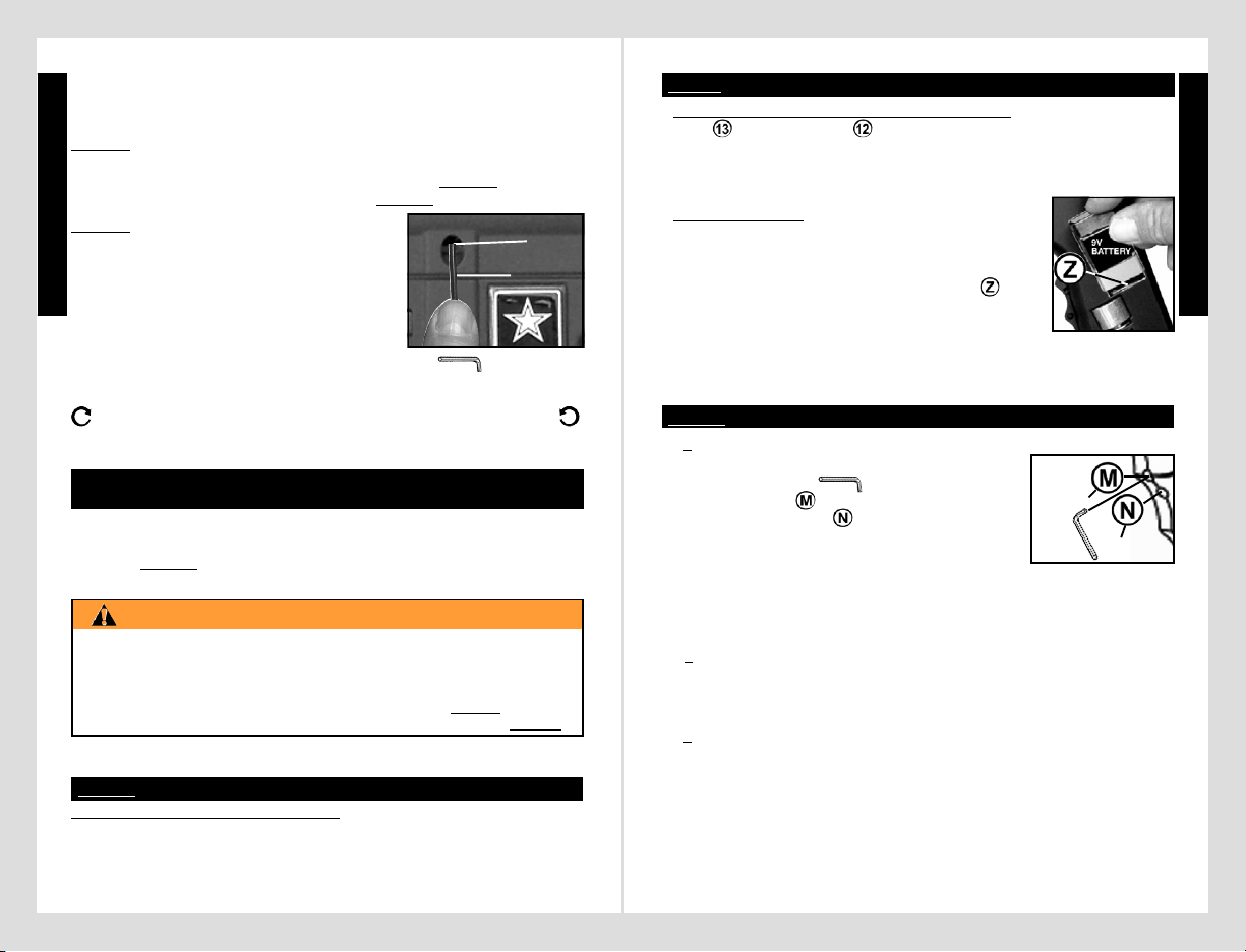
STEP 5) Velocity Adjustment
Each time you play paintball, the velocity of your
paintball marker should be checked with a
chronograph, an instrument for measuring velocity,
prior to playing paintball to verify that the marker’s
velocity is set below 300 feet per second or less if
required by playing field.
Velocity Adjustment
Screw
3/16” Allen
Wrench
To adjust the velocity use the 3/16” allen wrench included with
your marker. The velocity adjustment screw is located on left side
receiver. To adjust the velocity down, turn the screw inward or clockwise
. To turn the velocity up, turn the screw out or counterclockwise .
Do not remove the velocity screw.
sleeve installed and safety in Safe Mode, you are now ready to load
your hopper with paintballs. Fill the hopper and only remove barrel
sleeve and turn off the safety when ready to shoot.
Prepare the marker for disassembly. First follow ❏ Unloading Your
Marker and
❏
Air Supply Cylinder Removal instructions on page 14.
Never disassemble a marker that is under pressure or pressurize a
partially assembled marker.
• Remove Battery Clip/old battery (from marker).
❏
Remove the 2
bolts and the left grip ).
❏
Carefully work battery out of receiver
cutout bringing non-connected end out first. As you remove the battery
from the receiver, do not pull the wires off of the internal components.
❏
Carefully remove the old battery from battery clip connector.
❏ ❏
❏ ❏
❏
2) To turn OFF the E-TriggerTM electronics.
❏
Press and hold the
power button until the LED turns off, then release the Power Button.
NOTE: The trigger electronics are set to shut-off automatically after a
prolonged period of inactivity.
❏❏
❏❏
❏
3) To select a new firing mode:❏ With the electronics turned on,
each press / release of the power button will change the firing mode to
the next firing mode in the menu: (the LED will flash 1, 2, 3 or 4 times
to identify the firing mode you have selected).
9
E-TriggerTM Operating Instructions (continued from page 8)
THE 4 FIRING MODES ARE:
(continued on page 10)
THE 4 FIRING MODES ARE:
Default firing mode:
1) SEMI-AUTO = 1 pull / release of the trigger fires 1 time.
❏
1 flash of the LED light indicates SEMI-AUTO mode.
Hopper Installation (continued from page 7)
E-TRIGGERTMOPERATING INSTRUCTIONS
STEP 1: Prepare the marker for safety before any programming:
STEP 2: E-TriggerTM Battery Installation Or Replacement
STEP 3: NORMAL OPERATION:
Power
Button
LED
• Install new battery. ❏ Attach 9 volt battery to the
battery connector and be sure wires lay flat inside
the cutout area of receiver (as shown on page 19).
❏
Carefully tilt and insert your new battery, wire
attached end first, into receiver as shown
.
❏
Reinstall left receiver grip with 2 grip bolts.
Battery installation is complete.
❏ ❏
❏ ❏
❏
1) To Turn ON the E-Trigger to normal operation - Ready To Fire:
Without holding the trigger: Use a small object
like an allen wrench
to ❏ press and hold
the power button
(for about 5 seconds) until
the green LED light
comes on and then
release the power button.
❏
Your marker is now ready for normal operation
in the SEMI-AUTO Firing Mode: 1 pull of the trigger fires 1 time (This is
the Factory Default Firing Mode Setting).
NOTE: If pressing the power button failed to turn on the LED light, see
troubleshooting on page 10.
NOTE: The E-Trigger Low Battery Indicator feature: the “Ready To
Fire” solid Green LED will turn to red when the battery is low and needs
replaced.
E
N
G
L
I
S
H
•
Remove Battery Clip/old battery (from marker). ❏ Remove the 2
bolts
and the left grip ).❏ Carefully work battery out of receiver
cutout bringing non-connected end out first. As you remove the battery
from the receiver, do not pull the wires off of the internal components.
❏
Carefully remove the old battery from battery clip connector.
❏ ❏
❏ ❏
❏
2) To turn OFF the E-TriggerTM electronics.
❏
Press and hold the
power button until the LED turns off, then release the Power Button.
NOTE: The trigger electronics are set to shut-off automatically after a
prolonged period of inactivity.
❏❏
❏❏
❏
3) To select a new firing mode:❏ With the electronics turned on,
each press / release of the power button will change the firing mode to
the next firing mode in the menu: (the LED will flash 1, 2, 3 or 4 times
to identify the firing mode you have selected).
9
E-TriggerTM Operating Instructions (continued from page 8)
THE 4 FIRING MODES ARE:
(continued on page 10)
THE 4 FIRING MODES ARE:
Default firing mode:
1) SEMI-AUTO = 1 pull / release of the trigger fires 1 time.
❏
1 flash of the LED light indicates SEMI-AUTO mode.
STEP 2: E-TriggerTM Battery Installation Or Replacement
STEP 3: NORMAL OPERATION:
E
N
G
L
I
S
H
11
10
E
N
G
L
I
S
H
THE 4 FIRING MODES ARE: (continued from page 9)
PROBLEM: The LED light does not light when you push the power button.
1) Battery may be disconnected.
❏
Check battery clip connection.
2) Battery may be bad -
❏
Check the battery, replace if bad.
3) Internal wire may be disconnected. Do NOT disassemble a marker
while it is pressurized with air.
❏
Inspect wire connections inside the
receiver: follow disassembly / wire inspection and assembly instructions
on pages 16-19 then continue on page 9 with
STEP 3: Normal Operation.
PROBLEM: You have successfully installed the battery, turned on the
E-Trigger
TM
, installed the air supply and loaded the paintballs and the
marker will not fire.
❏
Check to be sure safety is in FIRE position and
❏
make sure sufficient air supply is hooked up to the marker.
PROBLEM: the "Ready To Fire" solid Green LED has turned to red.
Low battery condition - While performance will vary while the LED is
red, the E-Trigger
TM
will still function under this condition until the battery
has lost power to the point that it will not cycle the marker.
❏
The battery
is low and needs replaced.
NOTE: If a problem still exists, call Tippmann
®
Service Department at
1-800-533-4831.
• You are now ready to go back to page 7 and complete the GETTING
STARTED section steps:
STEP 2:, STEP 3:, STEP 4: and STEP 5: .
NOTE: If marker does not fire see Troubleshooting below.
Press mode button to get:
2) TRIPLE FIRE = (3 shots in 0.25 seconds for one pull of the trigger).
❏
2 flashes of the LED light indicates TRIPLE FIRE mode.
Press mode button to get:
3) FULL-AUTO NORMAL = (12 shots per second): To fire in Full-Auto
Normal mode you must pull the trigger 4 single pulls within 1.00 second and
hold the 4th pull to fire 12 shots per second until you release the trigger).
❏
3 flashes of the LED light indicates FULL-AUTO NORMAL mode.
Press mode button to get:
4) FULL-AUTO FAST = (15 shots per second): To fire in Full-Auto Fast
mode you must pull the trigger 4 single pulls within 1.00 second and hold
the 4th pull to fire 15 shots per second until you release the trigger).
❏
4 flashes of the LED light indicates FULL-AUTO FAST mode.
Press mode button to get:
1) SEMI-AUTO (Default firing mode - see above).
U.S. ARMY Alpha BlackTMMarker Line Specifications
Model ........................................................................... Alpha BlackTM Basic
Caliber ...................................................................................................... .68
Action ................................................. Semi-Automatic (open bolt blow-back)
Power/Air Supply ......................................... compressed air, nitrogen or CO
2
Hopper Capacity ....................................................................... 200 Paintballs
Ball Feed ........................................................................................... Gravity
Cycle Rate ........................................................................ 8 shots per second
Standard Barrel Length ................................................................ 11” / 28 cm
Overall Length (with standard barrel & no tank)................... 21.25” / 53.98 cm
Weight (without tank) .......................................................... 3.8 lbs. / 1.72 kg
Effective Range ............................................................ 150+ ft. / 46+ mètres
Velocity .............................................. Always measure your marker’s velocity
before playing paintball and never shoot at velocities in excess of 300 feet per
second (see instructions on page 8).
Model Specific ......................................... Alpha Black
TM
Basic E-Trigger
TM
Cycle Rate ................................................. Adjustable 8-15 shots per second
Overall Length (with standard barrel & no tank) .................... 21.25” / 53.98 cm
Weight (without tank)......................................................... 4.03 lbs. / 1.83 kg
Battery .................................................................................................. 9 Volt
Model Specific .......................................... Alpha Black
TM
Tactical Edition
Overall Length (with standard barrel & no tank) ... 28.63 - 32.5” / 72.71 - 82.55 cm
Weight (without tank) ........................................................ 4.73 lbs. / 2.14 kg
Model Specific ........................ Alpha Black
TM
Tactical Edition E-Trigger
TMT
Cycle Rate ................................................. Adjustable 8-15 shots per second
Overall Length (with standard barrel & no tank) ... 28.63 - 32.5” / 72.71 - 82.55 cm
Weight (without tank) ........................................................ 4.96 lbs. / 2.25 kg
Battery .................................................................................................. 9 Volt
TOURNAMENT LOCK: Because the E-TriggerTM board requires
a tool to turn it on and off, no tournament lock is necessary for
competition paintball.
E-TRIGGERTM TROUBLESHOOTING
11
E
N
G
L
I
S
H
U.S. ARMY Alpha BlackTMMarker Line Specifications
Model ........................................................................... Alpha BlackTM Basic
Caliber ...................................................................................................... .68
Action ................................................. Semi-Automatic (open bolt blow-back)
Power/Air Supply ......................................... compressed air, nitrogen or CO
2
Hopper Capacity ....................................................................... 200 Paintballs
Ball Feed ........................................................................................... Gravity
Cycle Rate ........................................................................ 8 shots per second
Standard Barrel Length ................................................................ 11” / 28 cm
Overall Length (with standard barrel & no tank)................... 21.25” / 53.98 cm
Weight (without tank) .......................................................... 3.8 lbs. / 1.72 kg
Effective Range ............................................................ 150+ ft. / 46+ mètres
Velocity .............................................. Always measure your marker’s velocity
before playing paintball and never shoot at velocities in excess of 300 feet per
second (see instructions on page 8).
Model Specific ......................................... Alpha Black
TM
Basic E-Trigger
TM
Cycle Rate ................................................. Adjustable 8-15 shots per second
Overall Length (with standard barrel & no tank) .................... 21.25” / 53.98 cm
Weight (without tank)......................................................... 4.03 lbs. / 1.83 kg
Battery .................................................................................................. 9 Volt
Model Specific .......................................... Alpha Black
TM
Tactical Edition
Overall Length (with standard barrel & no tank) ... 28.63 - 32.5” / 72.71 - 82.55 cm
Weight (without tank) ........................................................ 4.73 lbs. / 2.14 kg
Model Specific ........................ Alpha Black
TM
Tactical Edition E-Trigger
TMT
Cycle Rate ................................................. Adjustable 8-15 shots per second
Overall Length (with standard barrel & no tank) ... 28.63 - 32.5” / 72.71 - 82.55 cm
Weight (without tank) ........................................................ 4.96 lbs. / 2.25 kg
Battery .................................................................................................. 9 Volt

E
N
G
L
I
S
H
12
E
N
G
L
I
S
H
WARNING
DO NOT DISASSEMBLE THIS MARKER WHILE IT IS PRESSURIZED
WITH AIR. DO NOT PRESSURIZE A PARTIALLY ASSEMBLED MARKER.
Basic Parts List
Tippmann Customer Service
13
• For Tactical Edition markers Shroud and Collapsible stock parts (see page 16.
• For E-Trigger markers E-Trigger parts ( see page 18).
★alpha black★
TM
www.usarmypaintball.com
1-800-533-4831
www.tippmann.com
E
N
G
L
I
S
H
WARNING
DO NOT DISASSEMBLE THIS MARKER WHILE IT IS PRESSURIZED
WITH AIR. DO NOT PRESSURIZE A PARTIALLY ASSEMBLED MARKER.
Tippmann Customer Service
13
www.usarmypaintball.com
1-800-533-4831
www.tippmann.com

E
N
G
L
I
S
H
1514
E
N
G
L
I
S
H
Cleaning & Maintenance
(continued on page 15)
Unloading Your Marker
❏
Eye protection designed for paintball use must be worn by the user
and any person within range.
To unload your marker:
1)
❏
Install the barrel sleeve (see page 2).
2)
❏
Empty and remove the hopper.
3)
❏
Go to a designated firing area and remove the barrel sleeve.
4)
❏
Point your marker in a safe direction and fire several times to be
sure there are no balls lodged in the chamber and / or barrel.
IMPORTANT: Do not uncock your marker as uncocking your marker
may push a ball into the chamber or down into the barrel in which case
the ball will be hidden from view.
5)
❏
Install the barrel sleeve (see page 2).
6)
❏
Visually inspect the chamber for paintballs.
Air Supply Cylinder Removal
❏
Eye protection designed for paintball use must be worn by the user
and any person within range.
To remove a charged air supply cylinder:
1)
❏
Follow the Unloading Your Marker instructions above.
2)
❏
With the barrel sleeve installed, turn the cylinder approximately 3/4 of
a turn counterclockwise
or out. This allows the air supply pin valve
to close so that no air will enter the marker.
❏
Point the marker in a
safe direction and fire the remaining gas in the marker by pulling the
trigger until the marker stops firing. This may take 4-5 shots.
• If your marker continues to fire, the tank pin valve has not closed yet
(because of the variances in tank pin valve parts, each tank varies
slightly on exactly how far it should be turned) and
❏
you will have to
turn the tank counterclockwise
a little further and repeat this step
until the marker does not fire,
❏
then remove the tank.
• NOTE: If during this step - you turned the tank and it began to leak
before you pulled the trigger, the tank o-ring should be checked for
damage before reassembly.)
3) After air tank is removed,
❏
point & fire the marker in a safe direction
until stored air is completely discharged
NOTE: Before storing or disassembling be sure to follow
❏
Unloading
Your Marker and
❏
Air Supply Cylinder Removal instructions (see above).
❏
Install barrel sleeve (see page 2).
Storage (continued on page 16)
Cleaning & Maintenance
❏
Eye protection must be worn during disassembly / assembly. To
reduce the chance of accidental discharge: First follow
❏
Unloading
Your Marker and
❏
Air Supply Cylinder Removal instructions on page
14 and never disassemble a marker that is under pressure or pressurize
a partially assembled paintball marker.
• Follow warnings listed on the air supply cylinder for handling and storage.
• Familiarize yourself with instructions listed on air supply cylinder or
adaptor. Contact the air supply cylinder or adaptor manufacturer with
any questions.
• Do not use any petroleum based cleaning solvents.
• Do not use any cleaning solvents that come in aerosol cans. NOTE:
Petroleum based products and aerosol products can damage your
markers’ o-rings.
• To clean your paintball marker use a damp towel with water to wipe off
paint, oil, and debris. Use Tippmann
®
marker oil or other premium
marker oil to maintain your marker in good working condition.
• To clean inside the barrel. Depress the feed elbow lock and tip out
feed elbow . Insert metal tab of cable squeegee into breach, then
pull squeegee through barrel to remove debris.
• Inspect and lubricate the internal drive assembly parts:
❏
the front
bolt o-ring,
❏
the rear bolt o-ring, ❏ the linkage arm and ❏ the drive
spring / guide pin (see Drive Assembly Removal and Installation
instructions on pages 16 - 19).
• Inspect and lubricate the barrel o-ring and the air supply valve
o-ring with a few drops of oil.
Storage
Before storage unload and remove air supply (see page 14). Then
install Barrel Sleeve (see page 2) and put your marker in Safe Mode
(see page 4). You should store your marker in a dry area. Before
storing your marker make sure that the marker is cleaned and oiled (see
cleaning and maintenance on page 14) so that it does not rust. Store
Repairing Air Supply Cylinder Leaks
The most common leak occurs from a bad air supply valve o-ring. To
replace a valve o-ring you must first remove the bad o-ring and then
install a new one. This o-ring is located on the tip of your air supply
valve. The best valve o-rings are made of urethane. The urethane o-
rings are not affected by high air supply pressures. These may be
purchased from Tippmann
TM
or your local paintball dealer.
NOTE: If new valve o-ring does not resolve air supply leak, do not
attempt to repair air supply cylinder. Contact Tippmann
TM
or your local
paintball dealer.
Cleaning & Maintenance (continued from page 14)
1514
E
N
G
L
I
S
H
Storage (continued on page 16)
Your Marker and
❏
Air Supply Cylinder Removal instructions on page
14 and never disassemble a marker that is under pressure or pressurize
a partially assembled paintball marker.
• Follow warnings listed on the air supply cylinder for handling and storage.
• Familiarize yourself with instructions listed on air supply cylinder or
adaptor. Contact the air supply cylinder or adaptor manufacturer with
any questions.
• Do not use any petroleum based cleaning solvents.
• Do not use any cleaning solvents that come in aerosol cans. NOTE:
Petroleum based products and aerosol products can damage your
markers’ o-rings.
• To clean your paintball marker use a damp towel with water to wipe off
paint, oil, and debris. Use Tippmann
®
marker oil or other premium
marker oil to maintain your marker in good working condition.
• To clean inside the barrel. Depress the feed elbow lock and tip out
feed elbow . Insert metal tab of cable squeegee into breach, then
pull squeegee through barrel to remove debris.
• Inspect and lubricate the internal drive assembly parts:
❏
the front
bolt o-ring,
❏
the rear bolt o-ring, ❏ the linkage arm and ❏ the drive
spring / guide pin (see Drive Assembly Removal and Installation
instructions on pages 16 - 19).
• Inspect and lubricate the barrel o-ring and the air supply valve
o-ring with a few drops of oil.
Storage
Before storage unload and remove air supply (see page 14). Then
install Barrel Sleeve (see page 2) and put your marker in Safe Mode
(see page 4). You should store your marker in a dry area. Before
storing your marker make sure that the marker is cleaned and oiled (see
cleaning and maintenance on page 14) so that it does not rust. Store
Repairing Air Supply Cylinder Leaks
The most common leak occurs from a bad air supply valve o-ring. To
replace a valve o-ring you must first remove the bad o-ring and then
install a new one. This o-ring is located on the tip of your air supply
valve. The best valve o-rings are made of urethane. The urethane orings are not affected by high air supply pressures. These may be
purchased from Tippmann
TM
or your local paintball dealer.
NOTE: If new valve o-ring does not resolve air supply leak, do not
attempt to repair air supply cylinder. Contact Tippmann
TM
or your local
paintball dealer.
Cleaning & Maintenance (continued from page 14)

17
E
N
G
L
I
S
H
16
E
N
G
L
I
S
H
❏
With left half removed, pull the end cap out to remove the guide pin
and drive spring (these parts must be removed before the bolt handle
can be removed). Disconnect the linkage arm from the rear and front
bolts. Slide the front bolt off the power tube and check the o-ring. Clean
and oil the o-ring or if damaged, replace with a new one. Do the same
with the rear bolt o-ring.
Marker Disassembly / Assembly
(continued on page 18)
Marker Disassembly (continued on page 17)
Marker Disassembly (continued from page 16)
❏
Valve removal from power tube: If it is necessary to remove the valve,
use a wrench ( ) to slowly unscrew the gas line fitting. Once the
fitting is out, the valve will slide out the back of the power tube.
NOTE:
❏
Check the external valve o-ring and if damaged, replace with
a new one. If the o-ring is damaged your marker will not function
correctly.
❏
Clean all parts and oil the o-rings.
❏
Reinstall the valve: Insert cleaned and oiled valve into the power tube
and align the holes of the valve and power tube.
❏
Apply teflon tape or
paste on threads of gas line fitting and carefully screw it into the valve
and snug with a wrench ( )(do not over tighten and strip threaded
parts).
❏
Wipe off any excess paste.
❏
Reinstall the power tube/valve into receiver: Apply red loctite #271
sealant to threads of two valve lock bolts and attach - do not
over tighten bolts and strip threads.
❏
Wipe off any excess paste.
Power tube and valve removal.
NOTE: Do not remove the gas line fitting unless it is leaking or you need
to replace the valve. If you should do so you will need some teflon tape
or paste to reinstall it. Carefully hand start all threaded parts and do not
overtighten and strip threaded parts when assembling.
❏
First, complete Marker Disassembly Instructions (see page 16).
❏
Power tube removal: To remove the power tube
and valve, unscrew the two valve lock
bolts from the right side receiver.
Storage (continued from page 15)
❏
To remove the left-side receiver , unscrew the 7 receiver
connection bolts ( 3 long -
) + (4 short - ). Then carefully lift the left-
side receiver to access the internal parts.
Marker Disassembly / Assembly
Eye protection must be worn during disassembly / assembly.
First follow
❏
Unloading Your Marker and ❏ Air Supply Cylinder Removal
instructions on page 14. Do not pressurize a
partially assembled paintball marker.
❏
Remove the barrel unscrew .
❏
Remove the magazine ,
press the 2 tabs
in and slide it out. ❏ Turn the velocity screw in
until it stops.
❏
Loosen the 2 adapter bolts . ❏ Remove the feed
elbow
, press the feed lock , tilt the feed elbow out and slide it off
the receiver.
Tactical
Edition parts
Not Shown
In Basic
schematics
parts (on
pages
12-13).
TA06201
Collapsible Stock Assembly
(Replaces End Cap Cover )
TA06200
Shroud
NOTE: (if 2 adapter bolts are
removed, the short bolt goes in front
when reassembling).
Power
Button
LED
On
E-Trigger
Markers
TA09919
Bolt
NOTE: Carefully hand start
all threaded parts and do
not overtighten and strip
threaded parts
when assembling.
❏
Put the marker into the uncocked position.
To uncock the marker: Pull and hold the bolt
cocking handle
back - then pull the
trigger and release the handle slowly forward
which will uncock the marker.
your marker with the bolt in the forward position, uncocked.
When removing your marker out of storage make sure Barrel Sleeve is
installed (see page 2) and safety is in Safe Mode (see page 4). You
should re-oil the rear bolt and the front bolt o-ring before use (see
cleaning and maintenance on page 14).
17
E
N
G
L
I
S
H
❏
With left half removed, pull the end cap out to remove the guide pin
and drive spring (these parts must be removed before the bolt handle
can be removed). Disconnect the linkage arm from the rear and front
bolts. Slide the front bolt off the power tube and check the o-ring. Clean
and oil the o-ring or if damaged, replace with a new one. Do the same
with the rear bolt o-ring.
Marker Disassembly / Assembly
(continued on page 18)
Marker Disassembly (continued from page 16)
❏
Valve removal from power tube: If it is necessary to remove the valve,
use a wrench (
) to slowly unscrew the gas line fitting. Once the
fitting is out, the valve will slide out the back of the power tube.
NOTE:
❏
Check the external valve o-ring and if damaged, replace with
a new one. If the o-ring is damaged your marker will not function
correctly.
❏
Clean all parts and oil the o-rings.
❏
Reinstall the valve: Insert cleaned and oiled valve into the power tube
and align the holes of the valve and power tube.
❏
Apply teflon tape or
paste on threads of gas line fitting and carefully screw it into the valve
and snug with a wrench (
)(do not over tighten and strip threaded
parts).
❏
Wipe off any excess paste.
❏
Reinstall the power tube/valve into receiver: Apply red loctite #271
sealant to threads of two valve lock bolts and attach
- do not
over tighten bolts and strip threads.
❏
Wipe off any excess paste.
Power tube and valve removal.
NOTE: Do not remove the gas line fitting unless it is leaking or you need
to replace the valve. If you should do so you will need some teflon tape
or paste to reinstall it. Carefully hand start all threaded parts and do not
overtighten and strip threaded parts when assembling.
❏
First, complete Marker Disassembly Instructions (see page 16).
❏
Power tube removal: To remove the power tube
and valve, unscrew
the two valve lock
bolts
from the right side receiver.

19
E
N
G
L
I
S
H
18
E
N
G
L
I
S
H
Reassembling Receiver Halves:
STEP 1: ❏ Double check that the Trigger Assembly
; and other parts: Feed Elbow Lock + Pin + Spring ;
Ball Latch
; Front Bolt* ; Linkage Arm* ; Link Arm Pins (2)
; Rear Bolt* + Bolt Insert ; Bolt Handle ; Drive Spring* +
Guide Pin*
; Buffer O-ring ; End Cap + End Cap Cover ; 2
Tank Adapter Nuts
; are in place and (*=oiled) (see below and
schematics on pages 11–12 for details as needed).
❏ ❏
❏ ❏
❏
Non-E-TriggerTM Markers go to STEP 2) on page 19.
For E-TriggerTM Markers:
Do not operate sear tripper assembly uninstalled as solenoid /
armature may pinch you.
E-TriggerTMParts Not Shown
in Basic Parts List on
(pages 12-13)
TA06020 Armature Pin
TA09935
Electronics
Assembly
TA05014 Magnet
Solenoid
-Armature
02-88
Sear Spring
TA01135 Sear
STEP 2: ❏ Carefully install the left receiver half (make sure halves fit flush).
❏
Insert 4 short receiver bolts .
❏
If marker has a barrel shroud - insert it now.
❏
Insert 3 long receiver bolts and❏ Tighten the 7 bolts / .
❏
Attach adapter tighten 2 bolts (NOTE: short adapter
bolt goes in front).
❏
Apply marker oil onto the barrel o-ring, insert
the barrel and carefully screw it in.
❏
Slide the feed elbow into the receiver and tilt up until the feed lock
holds it in place.
❏
E-TriggerTM Markers - Attach a 9 volt battery to the
battery connector and be sure the wires lay flat inside
the cutout area of the receiver.
❏
Carefully tilt and insert the battery (wire attached
end first ) into the receiver.
❏
Install the left receiver grip with 2 bolts .
❏
Press in the 2 magazine tabs and slide the
magazine up into the marker until the tabs
lock it in place. NOTE: The magazine may be used
to store tools and lubricating oil for your marker
(shown with 2 allen wrenches and oil).
Reassembling Receiver Halves:
(continued on page 19)
❏
Double check that the E-TriggerTM Parts
are Positioned correctly for Reassembly
as follows:
❏
1) Place solenoid / (armature - fits
inside solenoid) into right receiver.
❏
2) Carefully align and insert the
electronics board
into slot.
❏
3) Place trigger switch on two pins
of right receiver half.
❏
4) Insert capacitor in slot.
❏
5) Route wires in cutout areas to lay flat under armature pin and
battery and not be pinched when receiver halves are reassembled.
❏
Visually inspect internal wires for disconnected wire end(s) or
damage.
❏
6) Insert armature pin into 2 slots so it moves freely.
❏
7) Insert Magnet in slot below armature as shown.
❏
Double check that all parts are in place as shown.
❏
Place battery connector through left receiver half ❏ make
sure the magnet fits into left receiver half slot so it does not break
and
❏
wires are not pinched as you ❏ place left half on right half so
the halves fit flush.
(E-Trigger
TM
Markers Go to STEP 2 on page 19).
Marker Disassembly / Assembly (continued from page 17)
Carefully hand start
all threaded parts and
do not overtighten and strip threaded parts when assembling.
Reassembling Receiver Halves: (continued from page 18)
19
E
N
G
L
I
S
H
STEP 2: ❏ Carefully install the left receiver half (make sure halves fit flush).
❏
Insert 4 short receiver bolts .
❏
If marker has a barrel shroud - insert it now.
❏
Insert 3 long receiver bolts and❏ Tighten the 7 bolts / .
❏
Attach adapter tighten 2 bolts (NOTE: short adapter
bolt goes in front).
❏
Apply marker oil onto the barrel o-ring, insert
the barrel
and carefully screw it in.
❏
Slide the feed elbow into the receiver and tilt up until the feed lock
holds it in place.
❏
E-TriggerTM Markers - Attach a 9 volt battery to the
battery connector and be sure the wires lay flat inside
the cutout area of the receiver.
❏
Carefully tilt and insert the battery (wire attached
end first
) into the receiver.
❏
Install the left receiver grip with 2 bolts .
❏
Press in the 2 magazine tabs and slide the
magazine
up into the marker until the tabs
lock it in place. NOTE: The magazine may be used
to store tools and lubricating oil for your marker
(shown with 2 allen wrenches
and oil).
Carefully hand start
all threaded parts and
do not overtighten and strip threaded parts when assembling.
Reassembling Receiver Halves: (continued from page 18)

21
If you should encounter any problems with your marker and you
have aftermarket parts on your marker, please test it with the
original stock parts before sending it in.
Always unload and remove air supply before shipping a marker (see
page 14). Do not ship your air supply tank if it is not completely empty.
For warranty and non-warranty repair:
1. Ship or deliver your product(s) to:
Tippmann Sports, LLC
2955 Adams Center Road
Fort Wayne, IN 46803
2. Postage or delivery charges must be prepaid.
3. Include a brief statement regarding the requested repair,
your name, return address and telephone number where
you can be reached during normal business hours, if possible.
Our policy is to complete the necessary repair work within 24
hours and return it to you via regular ground UPS. If you wish to
have it returned using a faster service, you can request for NEXT
DAY AIR UPS OR SECOND DAY AIR UPS. You will be charged
for this service and must include your credit card number with
the expiration date. Your card will be charged the difference in
additional cost over regular ground shipping service.
Tippmann Sports, LLC warrants that this product is found free
from defects in materials and workmanship for a period of 1
year from the original date of purchase by the initial owner/
purchaser. This warranty does not apply to defects discovered
after purchase which were caused by the unauthorized
modifications and alterations of our product. Tippmann Sports,
LLC will repair or replace, without charge, any of its markers
that have failed through defect in material or workmanship.
Tippmann
®
is dedicated to providing you with the ultimate paintball
marker and the quality support necessary for satisfactory play.
20
E
N
G
L
I
S
H
Register your marker either:
1. On line at www.
usarmypaintball.com or...
2. Complete the attached registration card and mail to the above address.
E
N
G
L
I
S
H
THIS PAGE INTENTIONALLY LEFT BLANK.
WARRANTY AND REPAIR POLICY
WARRANTY OR REPAIR PROCEDURE
WARRANTY REGISTRATION
21
E
N
G
L
I
S
H
THIS PAGE INTENTIONALLY LEFT BLANK.
ADVERTENCIA
2
1
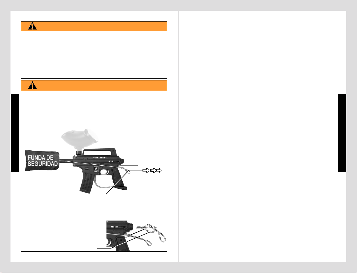
• EXCEPTO CUANDO SU MARCADOR ESTE EN USO, SIEMPRE
ASEGÚRESE DE QUE EL BOTÓN DE SEGURIDAD DEL
GATILLO, SE ENCUENTRE EN POSICIÓN (SAFE) DE
SEGURIDAD (VER INSTRUCCIONES PÁGINA 3), Y QUE LA
FUNDA DE SEGURIDAD, ESTE INSTALADA ADECUADAMENTE
EN EL BARRIL DEL MARCADOR COMO SE MUESTRA ABAJO.
1) DESLICE EL BARRIL DENTRO DE LA FUNDA DE SEGURIDAD
Y ABRACE CON EL CORDÓN ELÁSTICO LA PARTE SUPERIOR
DEL RECIBIDOR Y ASEGÚRELO EN LA PARTE POSTERIOR
DEL MANGO COMO SE MUESTRA ABAJO.
INSTALACIÓN DE LA FUNDA DE SEGURIDAD
ADVERTENCIA
FELICITACIONES por su compra de el marcador paintball U.S. ARMY
Alpha BlackTM. Creemos que nuestra linea de marcadores Alpha Black
TM
son los mas precisos y durables disponibles en el mercado y son
orgullosamente fabricado por Tippmann
®
. Toda nuestra linea de
marcadores Alpha Black
TM
le daran muchos años de servicio si es utilizado
apropiadamente. Vea como puede maximizar todo el poder a su alcance
con su marcador en el lugar web www.usarmypaintball.com juegue en
forma inteligente….. juegue mas fuerte... Army Strong
SM
.
Antes de cargar o disparar este marcador por favor tome tiempo para
leer completamente este manual y empezar a familiarizarse con las
partes, operación y todas las precauciones de seguridad del marcador
Tippmann
®
Alpha BlackTM . Si alguna de sus partes no se encuentra, o
esta defectuosa y necesita asistencia, por favor comuníquese
con el departamento de Servicio al Cliente de Tippmann
®
al teléfono
1-800-533-4831 en donde le daremos un servicio oportuno y amable.
TABLA DE CONTENIDO
Advertencia ................................................................................................ 1
Advertencia - Instalación de la funda de seguridad ................................... 1
Advertencia/ Declaración de responsabilidad ............................................. 3
La Seguridad es su responsabilidad / Adopte Todos Los Cuidados Y Seguridad 3
Posición de Seguridad = activando la posición de seguridad (PUSH SAFE) 3
Posición de disparo = activando la posición de disparo (PUSH FIRE).......... 3
Inicio ........................................................................................................... 5
1. Prepare su marcador para la instalación del cilindro de suministro de aire.5
2. Instalación del cilindro de suministro de aire ....................................... 6
3. Instalación del Tolva de munición ........................................................ 7
4. Ajuste de velocidad de disparos y solución a problemas ..................... 7
5. Ajuste de Velocidad.............................................................................. 7
Diagramas esquemáticos de partes .......................................................... 11
Modelos de Marcadores y especificaciones .............................................. 13
Descargando su marcador......................................................................... 13
Remoción del cilindro de suministro de aire .............................................. 14
Limpieza y mantenimiento ......................................................................... 14
Desensamble / Reensamble del marcador ................................................ 15
Reparación de escapes del suministro de aire .......................................... 19
Almacenamiento ........................................................................................ 19
Garantía y Poliza de Reparación .............................................................. 20
Garantía o procedimiento de reparación .............................................. 20
Registro de garantía .............................................................................. 20
BOTÓN
DE AJUSTE
LONGITUD
DEL CABLE
ELÁSTICO
E
S
P
A
Ñ
O
L
E
S
P
A
Ñ
O
L
2955 Adams Center Road, Fort Wayne, IN 46803 USA
P) 260-749-6022 • F) 260-749-6619 • www.tippmann.com • www.usarmypaintball.com
★alpha black★
ESTO NO ES UN JUGUETE. UN USO INAPROPIADO PUEDE
CAUSAR SERIAS HERIDAS O LA MUERTE. OJOS, CARA Y
OIDOS DEBEN SER PROTEGIDOS TODO EL TIEMPO, CON
LA PROTECCIÓN DISEÑADA PARA PAINTBALL TANTO PARA
JUGADORES COMO PARA CUALQUIER PERSONA QUE ESTE
EN EL RADIO DE ALCANCE. RECOMENDAMOS AL MENOS
18 AÑOS PARA LA COMPRA Y USO. LAS PERSONAS
MENORES DE 18 AÑOS DEBEN USAR ESTE PRODUCTO
BAJO LA SUPERVISIÓN DE UN ADULTO. ANTES DE USAR
ESTE PRODUCTO LEA EL MANUAL DEL USUARIO.
2) EN LA POSICIÓN
DESEADA, AJUSTE EL
SEGURO PLÁSTICO
MANTENIENDO EL CABLE ELÁSTICO
TEMPLADO CONTRA LA PARTE POSTERIOR DEL MANGO.
3) ASEGÚRESE DE DEJAR SUFICIENTE ELASTICIDAD EN EL
CORDÓN PARA PODER HALAR POR ENCIMA DEL
MARCADOR, PARA ASÍ REMOVER LA FUNDA
DE SEGURIDAD PARA DISPARAR.
4) UNA VEZ LA LONGITUD DE EL
CABLE ELÁSTICO SE HA DEFINIDO,
HAGA UN NUDO, AJUSTANDOLO
CONTRA EL SEGURO
PLÁSTICO COMO SE OBSERVA.
2
FELICITACIONES por su compra de el marcador paintball U.S. ARMY
Alpha BlackTM. Creemos que nuestra linea de marcadores Alpha Black
TM
son los mas precisos y durables disponibles en el mercado y son
orgullosamente fabricado por Tippmann
®
. Toda nuestra linea de
marcadores Alpha Black
TM
le daran muchos años de servicio si es utilizado
apropiadamente. Vea como puede maximizar todo el poder a su alcance
con su marcador en el lugar web www.usarmypaintball.com juegue en
forma inteligente….. juegue mas fuerte... Army Strong
SM
.
Antes de cargar o disparar este marcador por favor tome tiempo para
leer completamente este manual y empezar a familiarizarse con las
partes, operación y todas las precauciones de seguridad del marcador
Tippmann
®
Alpha BlackTM . Si alguna de sus partes no se encuentra, o
esta defectuosa y necesita asistencia, por favor comuníquese
con el departamento de Servicio al Cliente de Tippmann
®
al teléfono
1-800-533-4831 en donde le daremos un servicio oportuno y amable.
TABLA DE CONTENIDO
Advertencia ................................................................................................ 1
Advertencia - Instalación de la funda de seguridad ................................... 1
Advertencia/ Declaración de responsabilidad ............................................. 3
La Seguridad es su responsabilidad / Adopte Todos Los Cuidados Y Seguridad 3
Posición de Seguridad = activando la posición de seguridad (PUSH SAFE) 3
Posición de disparo = activando la posición de disparo (PUSH FIRE) .......... 3
Inicio ........................................................................................................... 5
1. Prepare su marcador para la instalación del cilindro de suministro de aire.5
2. Instalación del cilindro de suministro de aire ....................................... 6
3. Instalación del Tolva de munición ........................................................ 7
4. Ajuste de velocidad de disparos y solución a problemas ..................... 7
5. Ajuste de Velocidad.............................................................................. 7
Diagramas esquemáticos de partes .......................................................... 11
Modelos de Marcadores y especificaciones ..............................................13
Descargando su marcador......................................................................... 13
Remoción del cilindro de suministro de aire .............................................. 14
Limpieza y mantenimiento ......................................................................... 14
Desensamble / Reensamble del marcador ................................................ 15
Reparación de escapes del suministro de aire .......................................... 19
Almacenamiento ........................................................................................ 19
Garantía y Poliza de Reparación .............................................................. 20
Garantía o procedimiento de reparación .............................................. 20
Registro de garantía .............................................................................. 20
E
S
P
A
Ñ
O
L
2955 Adams Center Road, Fort Wayne, IN 46803 USA
P) 260-749-6022 • F) 260-749-6619 • www.tippmann.com • www.usarmypaintball.com
★alpha black★

• EXCEPTO CUANDO SU MARCADOR
ESTE EN USO, SIEMPRE ASEGÚRESE
QUE LA FUNDA DE SEGURIDAD DEL
BARRIL ESTE INSTALADA (VER
PÁGINA 1) Y QUE EL SEGURO DEL
GATILLO ESTE EN POSICIÓN DE SEGURO,
DESACTIVANDO EL GATILLO.
• PARA ACTIVAR LA POSICIÓN DE SEGURIDAD: (PUSH SAFE)
HAGA PRESIÓN EN EL SEGURO COMO SE VE.
• PARA DESACTIVAR LA POSICIÓN DE SEGURO (LISTO PARA
DISPARAR): (PUSH FIRE) HAGA PRESIÓN EN EL MISMO
BOTÓN AL RÉVES.
4
La Seguridad Es Su Responsabilidad (viene de la página 3)
3
La seguridad Es Su Responsabilidad
(continua en la página 4)
LA SEGURIDAD ES SU RESPONSABILIDAD:
ADVERTENCIA
PRESIONE EL BOTÓN
DE SEGURIDAD
MANTENGA EL GATILLO EN LA POSICIÓN DE SEGURIDAD
Advertencia Y Declaración De Responsabilidad:
Este marcador esta clasificado como una arma peligrosa y es entregada
por Tippmann Sports, LLC; con el entendimiento que el comprador asume
toda la responsabilidad del resultado de un manejo inseguro, o cualquier
acción que constituya una violación de las leyes o regulaciones
aplicables. Tippmann Sports, LLC no se hace responsable por ninguna
injuria personal, pérdida de propiedad o la vida como resultado del uso
de esta arma bajo ninguna circunstancia, incluyendo una descarga
imprudente, negligente o accidental.
Toda la información contenida en este manual esta sujeta a cambios sin
ninguna notificación. Tippmann Sports, LLC se reserva todos los derechos
de hacer cambios o mejoras del producto sin incurrir en ninguna obligación,
de incorporar tales mejoras en los productos previamente vendidos.
Si usted como usario no acepta la responsabilidad que Tippmann Sports,
LLC requiere, no utilice este marcador. SI lo usa de esta forma usted
libera a Tippmann Sports, LLC de cualquiera y de todas las
responsabilidades que asociadas con su manejo.
El propietario de esta arma asume la total responsabilidad por su
seguridad y el uso legal. Usted debe observar y tener las mismas
precauciones de seguridad que tendría con un arma de fuego,
asegurándose no solo por su seguridad sino por cualquiera alrededor
de usted. Todo el tiempo que el usuario use el marcador sea cauteloso.
El deporte de Paintball debe ser visto y juzgado bajo una conducta deportiva
y de seguridad. Siempre recuerde que el juego de Paintball puede sobrevivir
E
S
P
A
Ñ
O
L
La seguridad Es Su Responsabilidad
(continua en la página 5)
y crecer si permanece SEGURO.
• No cargue o dispare este marcador hasta que usted haya leído
completamente este manual y este familiarizado con su manejo seguro,
operación mecánica y características de manejo.
• Mantenga su dedo lejos del gatillo hasta que este listo a disparar.
• Nunca mire dentro del barril del marcador. Una descarga accidental en
un ojo, le puede causar una lesión permanente o la muerte.
• Mantenga el marcador en posición de seguro, hasta cuando este listo
para disparar (ver página 3).
• Mantenga el barril conectado a la funda de seguridad cuando no esta en uso.
• Nunca apunte el marcador, si no tiene intenciones de disparar.
• Nunca dispare su marcador a cualquier objeto que no tenga la intención
de disparar; porque pueden haber bolas o residuos almacenados en la
cámara, barril y o en la válvula de el marcador.
• No dispare a objetos frágiles como ventanas.
• Nunca dispare su marcador a propiedad privada de otros, pues la pintura
puede manchar autómoviles y casas.
• Siempre tenga el protector apuntando hacia abajo, o en una dirección
segura, aún cuando usted tropieze o caiga.
• La protección de ojos, cara y orejas diseñada específicamente, para
detener las bolas de pintura en la forma de gafas y máscara, deben cumplir
con las especificaciones F 1776 de la ASTM, la cual determina que debe
ser utilizada por el usuario o cualquier otra persona que este dentro del
radio de alcance.
• Nunca dispare a una persona que no tenga la protección de ojos, cara y
orejas diseñadas para paintball.
• Presurice y cargue el marcador, solo cuando el marcador vaya a ser
inmediatamente utilizado.
• NOTA: Antes de guardar o desensamblar, asegúrese de remover las bolas
de pintura y el suministro de aire. Siga las instrucciones en las paginas 13-14
para desarmar y retirar la fuente de aire. Instale la funda de seguridad del
barril (ver página 1).
• Almacene el marcador descargado y desgasificado en un lugar seguro.
• No desensamble el marcador mientras este presurizado.
• Vistase apropiadamente cuando juegue paintball. Evite exponer cualquier
parte de la piel cuando juegue paintball. Aún algo delgado, absorverá
parte del impacto y lo protegerá de las bolas de pintura.
• Mantenga las areas de piel expuesta, alejadas en caso de algún escape
de gas cuando instale o remueva el cilindro de suministro de aire. El aire
comprimido CO
2 y el Nitrógeno son gases muy frios y pueden causar
quemaduras bajo ciertas condiciones.
• Solamente use paintballs de calibre .68. Nunca carque o dispare
a objetos extraños.
E
S
P
A
Ñ
O
L
ADOPTE TODOS LOS CUIDADOS Y SEGURIDAD
4
La Seguridad Es Su Responsabilidad (viene de la página 3)
La seguridad Es Su Responsabilidad
(continua en la página 5)
y crecer si permanece SEGURO.
• No cargue o dispare este marcador hasta que usted haya leído
completamente este manual y este familiarizado con su manejo seguro,
operación mecánica y características de manejo.
• Mantenga su dedo lejos del gatillo hasta que este listo a disparar.
• Nunca mire dentro del barril del marcador. Una descarga accidental en
un ojo, le puede causar una lesión permanente o la muerte.
• Mantenga el marcador en posición de seguro, hasta cuando este listo
para disparar (ver página 3).
• Mantenga el barril conectado a la funda de seguridad cuando no esta en uso.
• Nunca apunte el marcador, si no tiene intenciones de disparar.
• Nunca dispare su marcador a cualquier objeto que no tenga la intención
de disparar; porque pueden haber bolas o residuos almacenados en la
cámara, barril y o en la válvula de el marcador.
• No dispare a objetos frágiles como ventanas.
• Nunca dispare su marcador a propiedad privada de otros, pues la pintura
puede manchar autómoviles y casas.
• Siempre tenga el protector apuntando hacia abajo, o en una dirección
segura, aún cuando usted tropieze o caiga.
• La protección de ojos, cara y orejas diseñada específicamente, para
detener las bolas de pintura en la forma de gafas y máscara, deben cumplir
con las especificaciones F 1776 de la ASTM, la cual determina que debe
ser utilizada por el usuario o cualquier otra persona que este dentro del
radio de alcance.
• Nunca dispare a una persona que no tenga la protección de ojos, cara y
orejas diseñadas para paintball.
• Presurice y cargue el marcador, solo cuando el marcador vaya a ser
inmediatamente utilizado.
• NOTA: Antes de guardar o desensamblar, asegúrese de remover las bolas
de pintura y el suministro de aire. Siga las instrucciones en las paginas 13-14
para desarmar y retirar la fuente de aire. Instale la funda de seguridad del
barril (ver página 1).
• Almacene el marcador descargado y desgasificado en un lugar seguro.
• No desensamble el marcador mientras este presurizado.
• Vistase apropiadamente cuando juegue paintball. Evite exponer cualquier
parte de la piel cuando juegue paintball. Aún algo delgado, absorverá
parte del impacto y lo protegerá de las bolas de pintura.
• Mantenga las areas de piel expuesta, alejadas en caso de algún escape
de gas cuando instale o remueva el cilindro de suministro de aire. El aire
comprimido CO
2 y el Nitrógeno son gases muy frios y pueden causar
quemaduras bajo ciertas condiciones.
• Solamente use paintballs de calibre .68. Nunca carque o dispare
a objetos extraños.
E
S
P
A
Ñ
O
L

6
INCIO: Para los modelos Tactical Edition: (viene de la página 5)
5
La Seguridad Es Su Responsabilidad (viene de la página 4)
Para los modelos Tactical Edition::
(continua en la página 6)
PASO 1: Prepare su marcador para la Instalación del
Cilindro de suministro de Aire
• Evite bebidas alcohólicas antes y durante el uso de este marcador.
El manejo irresponsable del marcador bajo la influencia de drogas o
alcohol, es una despreocupación criminal a la seguridad pública.
• Evite disparar a sus oponentes a punto vacio (6 pies o menos).
• Para el manejo y almacenamiento sobre el cilindro de suministro de aire
o adaptador, siga las instrucciones. Si tiene alguna pregunta puede
contactar a fabricante de los cilindros de aire.
• Siempre mida la velocidad de su marcador antes de jugar paintball y nunca
dispare con velocidades que sobrepasen los (300 pies) 92 metros/seg.
(ver instrucciones página 7).
E
S
P
A
Ñ
O
L
E
S
P
A
Ñ
O
L
❏
Los protectores para ojos diseñados para paintball deben ser usados por
los jugadores y cualquier persona que este en el rango de alcance. No
presurise un marcador parcialmente ensamblado. No desensamble este
marcador mientras este presurizado.
PASO 2: Instalación del Cilindro de suministro de Aire
• No presurise un marcador parcialmente ensamblado.
• Primero instale la funda de seguridad del barril (Ver página 1).
• Luego coloque el gatillo en posición de Seguro ( PUSH SAFE ) ver página 3.
Lea Completamente Cada Uno De Estos Pasos Antes De Intentar Usarlo.
NOTA: Con mucho cuidado y usando su mano coloque todas las partes que
van en roscas sin apretarlas demasiado para no alterarlas.
• Para la marcador Tactical Edition que no tienen E-Trigger
TM
- ❏ siga
a el PASO 2.
• Para la marcador Tactical Edition con E-Trigger
TM
- ❏ Usted debe
primero leer y seguir las instrucciones de manejo de la E - Trigger
TM
en
( páginas 8 - 10 ) antes de realizar el PASO 2.
❏❏
❏❏
❏
Para los modelos Alpha BlackTMBasic:
• Instale el barril :❏ Aplique Aceite para marcadores en el anillo-O del
barril e introdusca el barril dentro del recibidor y con cuidado atornillelo
.
•
Instale la cubierta antes instale el barril . Para instalar la
cubierta :
❏
Retire el tornillo del recibidor y ❏ inserte la cubierta .
❏ ❏
❏ ❏
❏
Reemplace y ajuste el tornillo para sostener la cubierta en su lugar.
•
Instale el barril (con la cubierta instalada): ❏ Aplique aceite para
marcadores en el anillo-O de el barril
, inserte el barril dentro de la
cubierta / recibidor y con mucho cuidado atornillelo dentro
.
• Para la Alpha BlackTM Marcador Basico con E-TriggerTM - ❏ Usted debe
primero leer y seguir las instrucciones de manejo de la E-Trigger
TM
( e n
páginas 8 - 10) antes de realizar el
PASO 2 ver pàgina 6.
• Para la Alpha Black
TM
Marcador Basico que no tienen E-TriggerTM - ❏ siga a
el
PASO 2 ver pàgina 6.
❏❏
❏❏
❏
Para los modelos Alpha BlackTMTactical Edition :
• Instale la carga colapsible:
❏❏
❏❏
❏
Con el tapon posterior cubierto remuevalo (deslicelo para afuera).
❏❏
❏❏
❏
Delice la carga dentro de la cubierta .
❏❏
❏❏
❏
Inserte el tornillo y apriete con cuidado .
Haga presión
sobre el nivelador
para alargar o
acortar la longuitud.
Ajuste En La
Longitud:
acortar
alargar
• Para instalar el suministro de aire, lubrique el anillo-O de la válvula del
cilindro con un poco de aceite para marcador, después inserte la válvula del
cilindro, hasta el final dentro del adaptador del suministro de aire, en la
parte trasera del marcador. De vuelta al cilindro dentro del adaptador en
sentido de las manecillas del relog hasta que se detenga. Ajuste la
culata si es necesario. Su marcador estará listo para disparar, una vez
usted cambie de posición de seguro (PUSH SAFE ) a posición de disparo
( PUSH FIRE ). Si el tanque esta lleno y usted no escucha el suministro
de aire acoplarse, mire si el pin de la válvula esta demasiado corto o el
anillo-O de la válvula del pin esta dañado.
• Después usted necesita engatillar el
marcador, deslizando el tornillo
manualmente hacia atrás, hasta que
quede asegurado en el lugar .
Siempre mantenga el marcador
engatillado cuando el suministro de aire
este unido al marcador. Esto ayudará a
prevenir una descarga accidental.
INICIO: (continua en la página 7)
INICIO
6
INCIO: Para los modelos Tactical Edition: (viene de la página 5)
E
S
P
A
Ñ
O
L
PASO 2: Instalación del Cilindro de suministro de Aire
• No presurise un marcador parcialmente ensamblado.
• Primero instale la funda de seguridad del barril (Ver página 1).
• Luego coloque el gatillo en posición de Seguro ( PUSH SAFE ) ver página 3.
• Para la marcador Tactical Edition que no tienen E-Trigger
TM
- ❏ siga
a el
PASO 2.
• Para la marcador Tactical Edition con E-Trigger
TM
- ❏ Usted debe
primero leer y seguir las instrucciones de manejo de la E - Trigger
TM
en
( páginas 8 - 10 ) antes de realizar el
PASO 2.
• Instale la carga colapsible:
❏❏
❏❏
❏
Con el tapon posterior cubierto remuevalo (deslicelo para afuera).
❏❏
❏❏
❏
Delice la carga dentro de la cubierta .
❏❏
❏❏
❏
Inserte el tornillo y apriete con cuidado .
Haga presión
sobre el nivelador
para alargar o
acortar la longuitud.
Ajuste En La
Longitud:
acortar
alargar
• Para instalar el suministro de aire, lubrique el anillo-O de la válvula del
cilindro con un poco de aceite para marcador, después inserte la válvula del
cilindro, hasta el final dentro del adaptador del suministro de aire, en la
parte trasera del marcador. De vuelta al cilindro dentro del adaptador en
sentido de las manecillas del relog
hasta que se detenga. Ajuste la
culata si es necesario. Su marcador estará listo para disparar, una vez
usted cambie de posición de seguro (PUSH SAFE ) a posición de disparo
( PUSH FIRE ). Si el tanque esta lleno y usted no escucha el suministro
de aire acoplarse, mire si el pin de la válvula esta demasiado corto o el
anillo-O de la válvula del pin esta dañado.
• Después usted necesita engatillar el
marcador, deslizando el tornillo
manualmente hacia atrás, hasta que
quede asegurado en el lugar
.
Siempre mantenga el marcador
engatillado cuando el suministro de aire
este unido al marcador. Esto ayudará a
prevenir una descarga accidental.
INICIO: (continua en la página 7)

• Instale La Nueva Bateria: ❏ Conecte una nueva bateria
de 9 voltios al acople de conección y asegúrese que
los cables no queden aprisionados fuera del recibidor
( como se muestra en la página 18 ).
❏
Cuidadosamente incline e inserte la nueva bateria
( cables conectador primero ) dentro del recibidor
como se muestra.
❏
Reinstale el mango del recibidor izquierdo con
los dos tornillos.
8
E-TriggerTMInstrucciones De Manejo
(continua en la página 9)
7
E
S
P
A
Ñ
O
L
E
S
P
A
Ñ
O
L
❏❏
❏❏
❏
INSTALE EL SUMINISTRO DE AIRE Y CARGUE LA TOLVA CON BOLAS
DE PINTURA SOLO DESPUES DE:
❏❏
❏❏
❏
HABER INSTALADO LA FUNDA DE SEGURIDAD DEL BARRIL ( VER
PÁGINA 1 );
❏❏
❏❏
❏
HABER ACTIVADO EL BOTÓN DE SEGURO ( VER PÁGINA 3 );
❏❏
❏❏
❏
HABER INSTALADO LA BATERIA ( STEP 2 );
❏❏
❏❏
❏
ESTAR FAMILIARIZADO CON EL MANEJO NORMAL DEL
E-TRIGGER
TM
( PASO 3: ).
ADVERTENCIA
Lea y siga las instrucciones de manejo de la Alpha BlackTM E-TriggerTM (en las
pàginas 8-10 ) en forma completa antes de instalar el cilindro de suministro
de aire como se destaca en el PASO 2 de preparacion en la pàgina 6.
E-TRIGGERTMINSTRUCCIONES DE MANEJO
Prepare Su Marcador Para Ser Desensamblado:
❏
Antes de guardar o
desensamblar, siga las instrucciones
❏
Descargar Su Marcador y ❏ Remoción
Del Cilindro De Suministro De Aire (ver página 13/14).
❏
Los protectores para ojos diseñados para paintball deben ser usados
por los jugadores y cualquier persona que este en el rango de alcance.
PASO 5: Ajuste de la Velocidad
Antes de cada juego de paintball, la velocidad
de su marcador debe ser chequeada antes
con un cronómetro (instrumento de medición
de velocidad), a verificando que la velocidad
este por debajo de (300 pies) 92 metros/seg.
o menos si es requerido por las normas del
campo de juego.
PASO 4: Ajuste de velocidad de disparos y solución a problemas
• Para Marcadores con E-TriggerTM - lea las instrucciones de manejo (páginas
8-10), antes de pasar al
PASO 5.
• Para Marcadores que no tienen E-Trigger
TM
- Siga a el PASO 5.
Para ajustar la velocidad, use una llave allen
de 3/16''
que viene incluída con su marcador. El ajuste de velocidad
se hace con el tornillo localizado al lado izquierdo del recibidor. Para disminuir
la velocidad, mueva el tornillo en el sentido de la manecillas del reloj
.
Para aumentar la velocidad, mueva el tornillo en sentido contrario a las
manecillas del reloj
. (Nunca remueva el tornillo de control de velocidad).
PASO 3: Instalación de la Tolva de munición
• La funda de seguridad del barril debe estar instalada, (ver página 1) y en
posición de seguridad (ver página 3) antes de llenar la tolva de munición.
• Asegúrese que el codo de alimentación y la tolva de munición esten
limpias y libre de residuos para asegurar que la alimentacion de bolas
de pintura sea fluida.
• Instale el cuello de la tolva de municiones dentro del codo de alimentación
de su marcador y apriete la tolva de municiones abajo con una llave de
3/16”
que viene incluída con su marcador.
NOTA: No apriete demasiado el codo pues se puede romper. Con la
funda de seguridad del barril instalada y en la posición de seguridad
(Safe Mode) usted esta listo para cargar la tolva de municiones con
bolas de pintura. Llene la tolva de municiones y solo retire la funda
de seguridad del barril y gire a posición de disparo, el botón de
seguridad, cuando este listo para disparar.
el tornillo ajustar la
velocidad
3/16” llave
allen
INCIO: (viene de la página 6)
Lea Completamente Cada Uno De Estos Pasos Antes De Intentar Usarlo.
• Retire La Bateria Vieja De Su Marcador:
❏
Remueva el mango izquierdo
( 2 tornillos ).
❏
Con mucho cuidado retire la bateria sacando el lado que
no esta conectado primero. Mientras usted va retirando la bateria no hale
los cables internos de los otros componentes.
❏
Con mucho cuidado retire la bateria del acople de conección.
La instalacion de la bateria esta completa.
NOTA: Indicador de bateria baja en la E-Trigger
TM
: Cuando la luz en el tablero
cambia de verde " Listo para disparar" a rojo indica que la bateria esta baja y
requiere cambio.
PASO 1: Prepare su marcador en forma segura antes de programarlo:
PASO 2: E-Trigger
TM
instalación y remplazo de la bateria 9 voltios
• Instale La Nueva Bateria: ❏ Conecte una nueva bateria
de 9 voltios al acople de conección y asegúrese que
los cables no queden aprisionados fuera del recibidor
( como se muestra en la página 18 ).
❏
Cuidadosamente incline e inserte la nueva bateria
( cables conectador primero
) dentro del recibidor
como se muestra.
❏
Reinstale el mango del recibidor izquierdo con
los dos tornillos.
8
E-TriggerTMInstrucciones De Manejo
(continua en la página 9)
E
S
P
A
Ñ
O
L
❏❏
❏❏
❏
INSTALE EL SUMINISTRO DE AIRE Y CARGUE LA TOLVA CON BOLAS
DE PINTURA SOLO DESPUES DE:
❏❏
❏❏
❏
HABER INSTALADO LA FUNDA DE SEGURIDAD DEL BARRIL ( VER
PÁGINA 1 );
❏❏
❏❏
❏
HABER ACTIVADO EL BOTÓN DE SEGURO ( VER PÁGINA 3 );
❏❏
❏❏
❏
HABER INSTALADO LA BATERIA ( STEP 2 );
❏❏
❏❏
❏
ESTAR FAMILIARIZADO CON EL MANEJO NORMAL DEL
E-TRIGGER
TM
( PASO 3: ).
ADVERTENCIA
Lea y siga las instrucciones de manejo de la Alpha BlackTM E-TriggerTM (en las
pàginas 8-10 ) en forma completa antes de instalar el cilindro de suministro
de aire como se destaca en el
PASO 2 de preparacion en la pàgina 6.
E-TRIGGERTMINSTRUCCIONES DE MANEJO
Prepare Su Marcador Para Ser Desensamblado:
❏
Antes de guardar o
desensamblar, siga las instrucciones
❏
Descargar Su Marcador y ❏ Remoción
Del Cilindro De Suministro De Aire (ver página 13/14).
❏
Los protectores para ojos diseñados para paintball deben ser usados
por los jugadores y cualquier persona que este en el rango de alcance.
Lea Completamente Cada Uno De Estos Pasos Antes De Intentar Usarlo.
•
Retire La Bateria Vieja De Su Marcador: ❏ Remueva el mango izquierdo
( 2 tornillos ).
❏
Con mucho cuidado retire la bateria sacando el lado que
no esta conectado primero. Mientras usted va retirando la bateria no hale
los cables internos de los otros componentes.
❏
Con mucho cuidado retire la bateria del acople de conección.
La instalacion de la bateria esta completa.
NOTA: Indicador de bateria baja en la E-Trigger
TM
: Cuando la luz en el tablero
cambia de verde " Listo para disparar" a rojo indica que la bateria esta baja y
requiere cambio.
PASO 1: Prepare su marcador en forma segura antes de programarlo:
PASO 2: E-Trigger
TM
instalación y remplazo de la bateria 9 voltios

9 10
LAS 4 FUNCIONES DE DISPARO
(continua en la página 10)
E
S
P
A
Ñ
O
L
E
S
P
A
Ñ
O
L
LAS 4 FUNCIONES DE DISPARO (viene de la página 9)E-TriggerTMInstrucciones De Manejo (viene de la página 8)
PROBLEMA: La luz en el tablero no se enciende cuando presiono el botón de
encendido.
1) La bateria puede estar desconectada;
❏
Revise la coneccion de la bateria.
2) Bateria sin energia. ;
❏
Revise la bateria y reemplacela si esta mala.
3) La coneccion interna puede estar desconectada. No desensamble este
marcador mientras este presurizado con aire.
❏
Revise los cables de coneccion
internos como se indica en pàginas 15 - 18, luego continue en la página 9 con el
PASO 3: Manejo Normal. No presurise un marcador parcialmente ensamblado.
PROBLEMA: satisfactoriamente ha instalado la bateria luego prendio el marcador
E-Trigger
TM
, instalo el suminstro de aire, cargo las bolas de pintura y el marcador
no dispara.
❏
Verifique que el boton de seguridad este el posicion de DISPARO y revise si
el suminstro de aire esta correcto.
PROBLEMA: Usted ha instalado con exito la bateria, encendido el E-Trigger
TM
,
instalado el suministro y cargado la bolas de tinta y el marcador no hace disparos.
❏
Asegurese que el botón de seguridad se encuentra en posicion de disparo y
❏
asegurese que la fuente de aire esta conectada a el marcador.
PROBLEMA: La luz verde " Listo para Disparar" ha cambiado a rojo.
Condicion de Bateria Baja. Puede seguir usando su marcador con la luz roja,
este seguira funcionando hasta que se quede sin energia completamente.
❏
Reemplazo de la bateria.
NOTA: Si el problema persiste, comuniquese con el Departamento de Servicio
de Tippmann
®
al 1-800-533-4831.
SEGURO PARA TORNEOS: Debido a que la E-Trigger
TM
necesita de
una herramienta para encender o apagar, el seguro para torneo no es
necesario en competencias.
Su marcador esta listo para operar normal en
funcion 1) SEMI-AUTOMATICO = presione una vez / libere el gatillo
dispara solo 1 vez ( Esta funcion viene de fabrica.)
NOTA: Si al presionar el botón de encendido no se prende la luz del tablero, por
favor revise el manual de funcionamiento en la seccion de Soluciones página 10.
• Sin sostener el gatillo: Use un objeto pequeno
como una llave de Allan para
❏
hacer presion y
sotenga el botón de encendido
(por aprox. 5
segundos ) hasta que la luz verde
en el tablero
se prenda, luego libere el boton de encendido.
❏
1) Encendido de la E - TriggerTM y operacion normal - Listo para Disparar:
Botón de
encendido
La luz
LED
sostenga el gatillo en el cuarto para disparar 15 disparos por seguro hasta que
usted suelte el gatillo.
❏
4 intermitencias de la luz de tablero indiaca FULL AUTO FAST.
Haga presion sobre el botón para:
1) SEMI AUTO ( ajuste la función de disparo ver arriba).
❏
Ahora esta listo para regresar à la pàgina 6 y completar la seccion de
INICIA: PASO 2:, PASO 3:, PASO 4:,y PASO 5.
NOTA : si su marcador no dispara consulte solucion de problemas.
❏
2) Apague los componentes electronicos de la E-TriggerTM.
❏
Haga presion sobre el botón de encendio y sostengalo hasta que la luz en el
tablero se apague luego deje de hacer presion sobre el botón. NOTA: Los
gatillos electronicos estan hechos para apagarse automaticamente despues
de un tiempo prolongado de inactividad.
❏
3) Para seleccionar una nueva funcion de disparo:❏ 1) Con el
programador electronico prendido, suelte el boton de encendido cambiando
de una funcion de disparo a la siguiente funcion de disparo en el menu: ( La
luz en el tablero sera intermitente 1,2,3, o 4 veces para identificar la función
que ha seleccionado).
LAS 4 FUNCIONES DE DISPARO SON:
Esta funcion viene de fabrica:
1) SEMI-AUTOMATICO = 1 presione/ suelte el gatillo despues de el primer disparo.
❏
1 intermitente de la luz de el tablero indica la función de SEMI-AUTOMATICO
Presione el botón de funcion para:
2) DISPARO TRIPLE = ( 3 disparos en 0.25 segundos para cada vez que
presiona el gatillo).
❏
2 ensendidos de la luz de el tablero indiaca FUNCION DE TRES DISPAROS
Haga presion sobre el botón para:
3) FUNCION NORMAL AUTOMATICA = ( 12 disparos por segundo)
Para disparar en su totalidad la función Normal Automatica usted debe presionar
el gatillo 4 veces en 1.00 segundo, sostenga la presion del cuarto para disparar
12 disparos por segundo hasta que suelte el gatillo.
❏
3 intermitencias de la luz del tablero indica la function FULL AUTO NORMAL.
Haga presion sobre el botón para :
4) FULL AUTO FAST= ( 15 disparos por segundo): Para disparar en el Full Auto
Normal usted debe hacer presion sobre el gatillo 4 veces en un 1.00 segundo y
PASO 3: MANEJO NORMAL
E-TRIGGERTM SOLUCION A PROBLEMAS:
E
S
P
A
Ñ
O
L
LAS 4 FUNCIONES DE DISPARO (viene de la página 9)E-Trigger
PROBLEMA: La luz en el tablero no se enciende cuando presiono el botón de
encendido.
1) La bateria puede estar desconectada;
❏
Revise la coneccion de la bateria.
2) Bateria sin energia. ;
❏
Revise la bateria y reemplacela si esta mala.
3) La coneccion interna puede estar desconectada. No desensamble este
marcador mientras este presurizado con aire.
❏
Revise los cables de coneccion
internos como se indica en pàginas 15 - 18, luego continue en la página 9 con el
PASO 3: Manejo Normal. No presurise un marcador parcialmente ensamblado.
PROBLEMA: satisfactoriamente ha instalado la bateria luego prendio el marcador
E-Trigger
TM
, instalo el suminstro de aire, cargo las bolas de pintura y el marcador
no dispara.
❏
Verifique que el boton de seguridad este el posicion de DISPARO y revise si
el suminstro de aire esta correcto.
PROBLEMA: Usted ha instalado con exito la bateria, encendido el E-Trigger
TM
,
instalado el suministro y cargado la bolas de tinta y el marcador no hace disparos.
❏
Asegurese que el botón de seguridad se encuentra en posicion de disparo y
❏
asegurese que la fuente de aire esta conectada a el marcador.
PROBLEMA: La luz verde " Listo para Disparar" ha cambiado a rojo.
Condicion de Bateria Baja. Puede seguir usando su marcador con la luz roja,
este seguira funcionando hasta que se quede sin energia completamente.
❏
Reemplazo de la bateria.
NOTA: Si el problema persiste, comuniquese con el Departamento de Servicio
de Tippmann
®
al 1-800-533-4831.
SEGURO PARA TORNEOS: Debido a que la E-TriggerTM necesita de
una herramienta para encender o apagar, el seguro para torneo no es
necesario en competencias.
sostenga el gatillo en el cuarto para disparar 15 disparos por seguro hasta que
usted suelte el gatillo.
❏
4 intermitencias de la luz de tablero indiaca FULL AUTO FAST.
Haga presion sobre el botón para:
1) SEMI AUTO ( ajuste la función de disparo ver arriba).
❏
Ahora esta listo para regresar à la pàgina 6 y completar la seccion de
INICIA:
PASO 2:, PASO 3:, PASO 4:,y PASO 5.
NOTA : si su marcador no dispara consulte solucion de problemas.
E-TRIGGERTM SOLUCION A PROBLEMAS:

ADVERTENCIA
NO DESENSAMBLE ESTE MARCADOR MIENTRAS ESTE PRESURIZADO.
NUNCA PRESURISE UN MARCADOR PARCIALMENTE ENSAMBLADO.
E
S
P
A
Ñ
O
L
E
S
P
A
Ñ
O
L
1211
Partes de Básicas
• Para las partes Tactical Edition: la cubierta de barril y la carga colapsible - ver pagina 15.
• Para partes E-Trigger
TM
- ver pagina 17.
★alpha black★
TM
www.usarmypaintball.com
El Departamento de Servicio
al Cliente de Tippmann
®
1-800-533-4831
www.tippmann.com
ADVERTENCIA
NO DESENSAMBLE ESTE MARCADOR MIENTRAS ESTE PRESURIZADO.
NUNCA PRESURISE UN MARCADOR PARCIALMENTE ENSAMBLADO.
E
S
P
A
Ñ
O
L
1211
www.usarmypaintball.com
El Departamento de Servicio
al Cliente de Tippmann
®
1-800-533-4831
www.tippmann.com

Especificaciones para la linea U.S. ARMY Alpha Black
TM
Modelo Basic ................................................... Tippmann® Alpha BlackTM Basic
Calibre .............................................................................................................. .68
Acción ..................................... Semi automática (tornillo abierto soplado-posterior)
Potencia / suministro de aire ............................. Aire comprimido, Nitrógeno o CO
2
Capacidad de laTolva.............................................................. 200 Bolas de pintura
Alimentacion Bolas ................................................................................. Gravedad
Longitud estandar del barril .................................................................. 11” / 28 cms
Longitud estandar (con barril estandar y sin tanque) .....................21.25” / 53.98 cms
Peso (sin tanque) ............................................................................. 3.8 lbs. / 1.72 kj
Rango de efectividad ............................................................ 150+ pies / 46+ metros
Ciclo .................................................................................... 8 Vueltas por segundo
Velocidad .................... Siempre mida la velocidad de su marcador, antes de iniciar
..... su sesión de juego y nunca dispare usando velocidades superiores a (300 pies)
92 metros/segundos (ver página 7).
Especificas del modelo ............................. Alpha Black
TM
Basicwith E-Trigger
TM
Ciclo ................................................................ Ajustable 8 - 15 vueltas por segundo
Peso (sin tanque) ........................................................................... 4.03 lbs. / 1.83 kj
Battery ....................................................................................................... 9 Voltios
Especificas del modelo ...................................... Alpha Black
TM
Tactical Edition
Longitud estandar (con barril estandar y sin tanque) .... 28.63” - 32.5” / 72.71 - 55.82 cms
Ciclo ................................................................................... 15 Vueltas por segundo
Peso (sin tanque) ........................................................................... 4.73 lbs. /2.14 kj
Especificas del modelo ............ Alpha Black
TM
Tactical Edition with E-Trigger
TM
Longitud estandar (con barril estandar y sin tanque) .... 28.63” - 32.5” / 72.71 - 55.82 cms
Ciclo ................................................................ Ajustable 8 - 15 vueltas por segundo
Peso (sin tanque) ........................................................................... 4.96 lbs./ 2.25 kj
Battery ....................................................................................................... 9 Voltios
14
E
S
P
A
Ñ
O
L
E
S
P
A
Ñ
O
L
13
Remoción Del Cilindro De Suministro De Aire
❏
Los protectores para ojos diseñados para paintball deben ser usados por los
jugadores y cualquier persona que este en el rango de alcance.
Para remover un cilindro de aire cargado:
1)
❏
Siga las instrucciones de descargando de su maracador ( ver página 13 ).
2)
❏
Con la funda de seguridad instalada, gire el cilindro aproximadamente 3/4
de vuelta en sentido contrario a las manecillas del reloj . Esto permite que
el pin de la válvula de suministro de aire, cierre de tal manera que no permita el
paso de aire al marcador.
❏
Apunte con su marcador en forma segura y dispare
el gas remanente halando el gatillo hasta que el mismo marcador deje de disparar.
(Esto puede tomar entre cuatro o cinco disparos).
• Si su marcador continua disparando, el pin de la válvula del tanque no ha
cerrado aún, (debido a las variantes en las partes de las válvulas, y que cada
tanque varia un poco uno de otro, especialmente en como se debe dar vuelta.);
❏
usted tendrá que mover el tanque en sentido contrario a las manecillas del
reloj , un poco más y repetir este paso hasta que el marcador no dispare,
❏
luego puede retirar el tanque.
NOTA: Si durante este paso usted dio vuelta al tanque y este presento
un escape antes de hacer algun disparo, el anillo-O del tanque debe ser
revisado y cambiado antes de reensamblarlo.
3)
❏
Despues de remover el tanque, apunte y dispare el marcador en
direccion segura hasta hasque que el tanque se desocupe completamente.
NOTA: Antes de guardar o
desensamblar asegurese de seguir las
instrucciones para
❏
Descargar Su Marcador y ❏ Remover el Cilindro
en las paginas 13 - 14.
Limpieza Y Mantenimiento
❏
Los protectores para ojos diseñados para paintball deben ser usados por los
jugadores y cualquier persona que este en el rango de alcance.
❏
Para reducir el riesgo de descarga accidental: Primero siga las instrucciones,
para
❏
Descargando Su Marcador y ❏ Remoción Del Cilindro De Suministro De
Aire descritas en las paginas 13 - 14.
❏
No desensamble este marcador
mientras este presurizado. No presurise un marcador parcialmente ensamblado.
• Siga las advertencias enumeradas en el cilindro de suministro de aire, para
manipulación y almacenamiento.
• Familiarizese con todas las instrucciones enumeradas para el suministro de
aire y el adaptador. Si tiene alguna duda contacte al fabricante.
• No use solventes o derivados a base de pétroleo.
• No use solventes o limpiadores en aerosol.
NOTA: Los productos que contengan petrolatos o aerosoles, pueden dañar los
anillos-O de su marcador.
• Para limpiar su marcador de paintball use una toalla húmeda con agua,
limpie y remueve pintura, aceite y desechos. Recomendamos el uso
Descargando Su Marcador
❏
Los protectores para ojos diseñados para paintball deben ser usados por
los jugadores y cualquier persona que este en el rango de alcance.
1)
❏
Instale funda del barril (ver página 1).
2)
❏
Para descargar su marcador, desocupe completamente la tolva de
municiones y remueva la tolva.
3)
❏
Vaya al area designada de disparo y remueva la funda del barril.
4) Después apunte su marcador en una dirección segura y dispare varias
veces asegurandose que no queden bolas atrapadas en la cámara y/o en el
barril. IMPORTANTE: No desactive su marcador ya que desactivandole
puede empujar una bola dentro de la cámara o más abajo dentro del barril,
en tal caso la bola sería perdida de vista.
5)
❏
Instale funda del barril (ver página 1).
6)
❏
Inspeccione visualmente la camara para las bolas de pintura.
Limpieza y Mantenimiento
(continua en la página 15
14
E
S
P
A
Ñ
O
L
Remoción Del Cilindro De Suministro De Aire
❏
Los protectores para ojos diseñados para paintball deben ser usados por los
jugadores y cualquier persona que este en el rango de alcance.
Para remover un cilindro de aire cargado:
1)
❏
Siga las instrucciones de descargando de su maracador ( ver página 13 ).
2)
❏
Con la funda de seguridad instalada, gire el cilindro aproximadamente 3/4
de vuelta en sentido contrario a las manecillas del reloj
. Esto permite que
el pin de la válvula de suministro de aire, cierre de tal manera que no permita el
paso de aire al marcador.
❏
Apunte con su marcador en forma segura y dispare
el gas remanente halando el gatillo hasta que el mismo marcador deje de disparar.
(Esto puede tomar entre cuatro o cinco disparos).
• Si su marcador continua disparando, el pin de la válvula del tanque no ha
cerrado aún, (debido a las variantes en las partes de las válvulas, y que cada
tanque varia un poco uno de otro, especialmente en como se debe dar vuelta.);
❏
usted tendrá que mover el tanque en sentido contrario a las manecillas del
reloj ,
un poco más y repetir este paso hasta que el marcador no dispare,
❏
luego puede retirar el tanque.
NOTA: Si durante este paso usted dio vuelta al tanque y este presento
un escape antes de hacer algun disparo, el anillo-O del tanque debe ser
revisado y cambiado antes de reensamblarlo.
3)
❏
Despues de remover el tanque, apunte y dispare el marcador en
direccion segura hasta hasque que el tanque se desocupe completamente.
NOTA: Antes de guardar o
desensamblar asegurese de seguir las
instrucciones para
❏
Descargar Su Marcador y ❏ Remover el Cilindro
en las paginas 13 - 14.
Limpieza Y Mantenimiento
❏
Los protectores para ojos diseñados para paintball deben ser usados por los
jugadores y cualquier persona que este en el rango de alcance.
❏
Para reducir el riesgo de descarga accidental: Primero siga las instrucciones,
para
❏
Descargando Su Marcador y ❏ Remoción Del Cilindro De Suministro De
Aire descritas en las paginas 13 - 14.
❏
No desensamble este marcador
mientras este presurizado. No presurise un marcador parcialmente ensamblado.
• Siga las advertencias enumeradas en el cilindro de suministro de aire, para
manipulación y almacenamiento.
• Familiarizese con todas las instrucciones enumeradas para el suministro de
aire y el adaptador. Si tiene alguna duda contacte al fabricante.
• No use solventes o derivados a base de pétroleo.
• No use solventes o limpiadores en aerosol.
NOTA: Los productos que contengan petrolatos o aerosoles, pueden dañar los
anillos-O de su marcador.
• Para limpiar su marcador de paintball use una toalla húmeda con agua,
limpie y remueve pintura, aceite y desechos. Recomendamos el uso
Limpieza y Mantenimiento
(continua en la página 15

16
❏
Retire el barril que esta suelto .
❏
Retire el magazine , haga presion en las dos aletas que estan
dentro y a un costado para sacarlo.
❏
De vuelta al el tornillo calibrador de velocidad hasta que se detenga.
❏
Suelte los 2 tornillos del adaptador .
❏
Retire el codo alimentador . Haga presion sobre el seguro de alimentacion
de tal forma que pueda inclinarlo para afuera y sacarlo del recibidor.
❏
Para remover la parte izquierda del recibidor , remueva los 7
tornillos de coneccion del recibidor / . Luego cuidadosamente, levante
la tapa teniendo acceso a la parte interior.
Con su mano derecha remueva el extremo de la cubierta, para retirar el pasador
y el resorte guia. Estas partes deben ser removidas, antes que los tornillos del
mango sean removidos. Desconecte el brazo conector, desde la parte inferior y
tornillos frontales. Deslizar la parte frontal del tonillo del tubo de potencia y
verifique el anillo-O. Limpie y engrase el anillo-O, si se encuentra dañado;
remplacelo. Haga lo mismo con el anillo-O del tornillo trasero.
Desensamble Del Marcador
(continua en la página 16)
Desensamble / Reensamble Del Marcador
❏
Debe usar protectores para sus ojos durante el desensamble / ensamble.
Primero siga las instrucciones, para
❏
Descargando Su Marcador y ❏ Remoción
Del Cilindro De Suministro De Aire descritas en las paginas 13 - 14.
❏
No
desensamble este marcador mientras este presurizado. No presurise un marcador
parcialmente ensamblado.
del aceite Tippmann
®
u otro aceite de alta calidad para marcadores,
para mantener su marcador funcionando correctamente. Inspeccione y
aceite con algunas gotas de aceite en los tornillos anillo-O frontales y
traseros. Inspeccione y aceite el anillo-O del barril y el anillo-O del
suministro de aire
• Para limpiar el barril: Primero haga persion en el seguro del codo de
alimentacion y saquelo. Inserte el cordon limpiador, luego hale para remover
todo el residuo almacenado.
❏
Inspeccione y lubrique le anillo-O del barril, el anillo-O de la valvula de
suminstro de aire, el ensamble interno de de la guia, el anillo-O de la parte
frontal y tracera, en brazo conector y el resorte y pasador de la guia (ver las
instrucciones de Desensamble / Reensamble en la pagina 15-18).
Limpieza y Mantenimiento (viene de la página 14)
E
S
P
A
Ñ
O
L
E
S
P
A
Ñ
O
L
15
Remosión de la válvula y tubo de potencia.
NOTA: No remueva la linea de gas, a no ser que exista un escape o
necesite reemplazar la válvula. Si es necesario hacerlo, necesitará
cinta de teflón o pasta para reinstalar. NOTA : Con mucho cuidado y
usando su mano coloque todas las partes que van en roscas sin apretarlas
demasiado para no alterarlas.
Remoción de la válvula del tubo de potencia: Si es necesario la remoción de
la válvula, utilice una llave de tuercas , que en forma muy lenta
desatornille el conector de la línea de gas. Una vez se ha removido, la
válvula se podrá deslizar hacia fuera por detrás del tubo de potencia.
NOTA: Revise el anillo-O de la válvula externa en este momento. Si el anillo-O
esta maltratado, el marcador no podra funcionar correctamente.
❏
Limpie todas
las partes y engrase el anillo-O.
Reinstalar la válvula:
❏
Inserte una valvula limpia y aceitada dentro de el tubo de
potencia y alinie los agujeros de la valvula con los de el tubo de potencia
❏
Use
cinta de Teflon o pasta en los acoples de la linea de gas, y muy lentamente
atornille la valvula con una llave , no los apriete demasiado.
❏
Retire
todo tipo de exceso de pasta.
Reinstalar el tubo de potencia y la válvula:
❏
Cuando este instalanda la válvula
coloque pegante Loctite #271 y selle a los tornillos de la válvula, no los apriete
demasiado.
Desensamble / Reensamble Del Marcador
(continua en la página 17)
Desensamble / Reensamble Del Marcador (viene de la página 15)
❏
Para remover el tubo de potencia / la valvula,
desatornille los dos tornillos que aseguran la valvula
a el recibidor de el lado derecho.
Ponga el marcador en posición de desengatillado.
Para desengatillar el marcador: presione y sontenga
el tornillo de la manija del gatillo
hacia atràs ,
❏
luego hale el gatillo y ❏ suelte la manija hacia
adelante muy despacio para adelante
con lo cual
quedara desengatillado el marcador.
NOTA : ( Si remueve los 2 tornillos de
el adaptador , los tornillos cortos van en
la parte frontal cuando reensamble ).
Las partes
Tactical
Edition no
se muestran
en los
esquemas
de las
páginas
11-12).
TA06201
El Ensamble de La Carga Contraíble
(Reemplasa la cubierta de la tapa
tracera de la tapa Tracera )
TA06200
la cubierta
Botón de
encendido
EnMarcador
E-Trigger
TA09919
Tornillo
NOTA : Con mucho cuidado
y usando su mano coloque
todas las partes que van en
roscas sin apretarlas
demasiado para
no alterarlas.
LED tablero
de luz
16
❏
Retire el barril que esta suelto .
❏
Retire el magazine , haga presion en las dos aletas que estan
dentro y a un costado para sacarlo.
❏
De vuelta al el tornillo calibrador de velocidad hasta que se detenga.
❏
Suelte los 2 tornillos del adaptador .
❏
Retire el codo alimentador . Haga presion sobre el seguro de alimentacion
de tal forma que pueda inclinarlo para afuera y sacarlo del recibidor.
❏
Para remover la parte izquierda del recibidor , remueva los 7
tornillos de coneccion del recibidor
/ . Luego cuidadosamente, levante
la tapa teniendo acceso a la parte interior.
Con su mano derecha remueva el extremo de la cubierta, para retirar el pasador
y el resorte guia. Estas partes deben ser removidas, antes que los tornillos del
mango sean removidos. Desconecte el brazo conector, desde la parte inferior y
tornillos frontales. Deslizar la parte frontal del tonillo del tubo de potencia y
verifique el anillo-O. Limpie y engrase el anillo-O, si se encuentra dañado;
remplacelo. Haga lo mismo con el anillo-O del tornillo trasero.
E
S
P
A
Ñ
O
L
Remosión de la válvula y tubo de potencia.
NOTA: No remueva la linea de gas, a no ser que exista un escape o
necesite reemplazar la válvula. Si es necesario hacerlo, necesitará
cinta de teflón o pasta para reinstalar. NOTA : Con mucho cuidado y
usando su mano coloque todas las partes que van en roscas sin apretarlas
demasiado para no alterarlas.
Remoción de la válvula del tubo de potencia: Si es necesario la remoción de
la válvula, utilice una llave de tuercas
, que en forma muy lenta
desatornille el conector de la línea de gas. Una vez se ha removido, la
válvula se podrá deslizar hacia fuera por detrás del tubo de potencia.
NOTA: Revise el anillo-O de la válvula externa en este momento. Si el anillo-O
esta maltratado, el marcador no podra funcionar correctamente.
❏
Limpie todas
las partes y engrase el anillo-O.
Reinstalar la válvula: ❏ Inserte una valvula limpia y aceitada dentro de el tubo de
potencia y alinie los agujeros de la valvula con los de el tubo de potencia
❏
Use
cinta de Teflon o pasta en los acoples de la linea de gas, y muy lentamente
atornille la valvula con una llave
, no los apriete demasiado. ❏ Retire
todo tipo de exceso de pasta.
Reinstalar el tubo de potencia y la válvula: ❏ Cuando este instalanda la válvula
coloque pegante Loctite #271 y selle a los tornillos de la válvula, no los apriete
demasiado.
Desensamble / Reensamble Del Marcador
(continua en la página 17)
Desensamble / Reensamble Del Marcador (viene de la página 15)
❏
Para remover el tubo de potencia / la valvula,
desatornille los dos tornillos
que aseguran la valvula
a el recibidor de el lado derecho.

17
Desensamble / Reensamble Del Marcador (viene de la página 16)
E
S
P
A
Ñ
O
L
E
S
P
A
Ñ
O
L
❏
1) Coloque la solonoide / armadura en su
lugar en el recibidor derecho.
❏
2) Cuidadosamente alinee el tablero
electronico
en el espacio diseñado.
❏
3) Coloque el botón de encendido del
gatillo sobre los dos pasadores de la mitad
derecha del recibidor.
❏
4) Coloque el condensador en el espacio.
❏
5) Coloque los cables sobre los canales
No use el ensamble de cierre no instalado como solonoide/ armadura
puede pellizcarlo.
Reensamble de la mitades del recibidor
Reensamble de la mitades del recibidor (viene de la página 17)
PASO 1: Asegúrese que el ensamble del gatillo
; y Asegure el codo + Pin + resorte , acople de enganche de bolas
; tornillo frontal* ; brazo conector* ; dos pasadores del brazo
conector*
; tornillo trasero* + tornillo inserción ; manija del tornillo
; resorte guía* y pasador guía* ; anillo-O Buffer ; tapón
posterior
; cover of the tapón posterior ; dos tuercas del adaptador
; en su posición y (*=engrasar). (Ver abajo y páginas 11 - 12 diagrama
esquemático de partes básicas si es necesario).
❏ ❏
❏ ❏
❏
NOTA: Para Modelos sin E-TriggerTM- Siga a el PASO 2 ( ver pagina 18 ).
Reensamble de la mitades del recibidor
(continua en la página 18)
18
PASO 2: ❏ Con cuidado instale la mitad izquierda de receptor ( Asegurese de
que las mitades ensamblan adecuadamente ).
❏
Luego reinserte los 4 tornillos cortos .
❏
Si el barril tiene una cubierta introduzcala ahora.
❏
Luego reinserte los 3
tornillos largos .
❏
Luego apriete los 7 tornillos / .
❏
Reinstale el adaptador del tanque con dos tornillos N O TA:
cuando se re-ensablan el tornillo mas corto de el adaptador va en la parte frontal.
❏
Aceite el anillo-O del barril y inserte el barril con cuidado dele vuelta.
❏
Deslice el codo de alimentacion dentro de el recibidor y de vuelta hasta que
quede asegurado .
❏
E-TriggerTM marcadores - ❏ Introduzca una bateria de 9
voltios asegúrandose que los cables se encuentren planos y
no sean pellizcados.
❏
Cuidadosamente incline e inserte la
bateria ( asegure los cable primero ).
❏
Reinstale el mango del recibidor izquierdo con dos
tornillos .
❏
Haga presion en las dos aletas del recámara y
deslice la recámara dentro de el marcador hasta
que queden aseguradas en su lugar. NOTA: La recámara
Puede ser usada para guarder las herramientas y aceite
lubricante para marcador. ( como se muestran 2 llaves
de Allen y aceite lubricante).
NOTA : Con
mucho cuidado y usando su mano coloque todas las
partes que van en roscas sin apretarlas demasiado para no alterarlas.
❏❏
❏❏
❏
NOTA: Para Modelos con E-TriggerTM :
❏
Asegúrese de que todas las partes estan
en el lugar adecuado para reensamble.
Partes de la E-TRIGGER
TM
(no incluye en lista las partes
estándar de la Basica ver
páginas 11-12).
TA09935
Ensamble del
electronico
TA05014
Disco Magnético
Solonoide
con Armadura
02-88
Resorte de cierre
TA01135
Cierre
TA06020
Pasador de armadurala parte móvil de la solenoid
diseñados de tal manera que quede una
superfice plana debajo de la parte móvil de la solonoide, el pasador
y la bateria.
❏
Inspeccione visualmente las conecciones interiors busque
desconecciones o roturas.
❏
6) Coloque el pasador de la armadura dentro de la ranura de tal
forma que se pueda mover libremente.
❏
7) Coloque el Disco Magnético en el espacio debajo de armadura.
❏
8) Asegúrese de que todas las partes estan en el lugar adecuado.
❏
9) Coloque los conectores de la bateria atravezando la mitad del
recibidor izquierdo como se hizo durante el remplazo de la mitad izquierda
en la mitad derecha ( no pellizque ningún cable ).
❏❏
❏❏
❏
Modelos con E-TriggerTM - Siga a el PASO 2 ( ver pagina 18 ).
E
S
P
A
Ñ
O
L
Reensamble de la mitades del recibidor (viene de la página 17)
18
PASO 2: ❏ Con cuidado instale la mitad izquierda de receptor ( Asegurese de
que las mitades ensamblan adecuadamente ).
❏
Luego reinserte los 4 tornillos cortos .
❏
Si el barril tiene una cubierta introduzcala ahora.
❏
Luego reinserte los 3
tornillos largos
.❏ Luego apriete los 7 tornillos / .
❏
Reinstale el adaptador del tanque con dos tornillos NO TA:
cuando se re-ensablan el tornillo mas corto de el adaptador va en la parte frontal.
❏
Aceite el anillo-O del barril y inserte el barril con cuidado dele vuelta.
❏
Deslice el codo de alimentacion dentro de el recibidor y de vuelta hasta que
quede asegurado
.
❏
E-TriggerTM marcadores - ❏ Introduzca una bateria de 9
voltios asegúrandose que los cables se encuentren planos y
no sean pellizcados.
❏
Cuidadosamente incline e inserte la
bateria ( asegure los cable primero
).
❏
Reinstale el mango del recibidor izquierdo con dos
tornillos
.
❏
Haga presion en las dos aletas del recámara y
deslice la recámara
dentro de el marcador hasta
que queden aseguradas en su lugar. NOTA: La recámara
Puede ser usada para guarder las herramientas y aceite
lubricante para marcador. ( como se muestran 2 llaves
de Allen
y aceite lubricante).
NOTA : Con
mucho cuidado y usando su mano coloque todas las
partes que van en roscas sin apretarlas demasiado para no alterarlas.

Reparación De Escapes En El Cilindro De Aire
Los escapes de aire más comunes, ocurren cuando el anillo-O de la válvula
de suministro de aire se deteriora. Para remplazarlo usted debe remover
primero el anillo-O averiado y poner uno nuevo. Este anillo-O, esta localizado
en la punta de la válvula de suministro de aire. Los mejores anillos-O, estan
hechos de uretano. Los anillos-O de uretano, no se afectan con la alta
presión de aire. Estos pueden ser adquiridos directamente en Tippmann
®
o con
cualquiera de nuestros distribuidores locales. NOTA: Si un anillo-O nuevo no
resuelve el escape de aire, no intente reparar el cilindro de suministro de
aire. Contacte Tippmann
®
o su distribuidor de paintball más cercano.
Almacenaje
Antes de almacenar su marcador descargue y remueva el suministro de aire
(ver páginas 13 - 14). No desensamble este marcador mientras este
presurizado. No presurise un marcador parcialmente ensamblado. Luego,
instale la funda de seguridad del barril (ver página 1) y ponga su marcador en
la posición de seguro (PUSH SAFE - ver página 3). Usted debe almacenarlo
en un lugar seco. Antes de almacenarlo asegúrese que el marcador este
limpio y aceitado (ver limpieza y mantenimiento en la página 14) para que no
se oxiden. Almacene su marcador con la manija del tornillos hacia adelante
y desengatillado.
Cuando saque de nuevo su marcador, asegúrese que la funda de
seguridad del barril este instalada (ver página 1) y que el seguro este en
la posición de Safe (ver página 3). Usted debe aplicar aceite en los
anillos-O tornillos traseros y delanteros, antes de ser usados (ver limpieza
y mantenimiento en la página 14).
19
E
S
P
A
Ñ
O
L
E
S
P
A
Ñ
O
L
20
Si usted encontrará algún problema con nuestros marcadores y usted le ha
reemplazado alguna de las partes al marcador, por favor haga una prueba con
la partes originales antes de enviarla.
Siempre descargue y remueva el suministro de aire, antes de enviar el
marcador (ver instrucciones en las páginas 13 - 14). No nos envie el tanque
de suministro de aire si este, no esta completamente desocupado.
Para garantía y reparaciones sin garantía:
1. Envíe su producto a la siguiente dirección:
Tippmann Sports, LLC
2955 Adams Center Road
Fort Wayne, IN 46803
2. El costo del envío debe ser prepagado.
3. Incluya una corta descripción del problema, la reparación solicitada
con su nombre completo, dirección, número de télefono donde puede
ser localizado durante horas de oficina si es possible.
Nuesta poliza es completar la reparación necesaria en 24 horas y enviar
ésta via UPS regular. Si usted desea recibirla más rápidamente que el
servicio regular por tierra, usted puede solicitar envio de Entrega Aerea
Inmediata Al Siguiente Dia. o al Segundo Dia Via UPS. Usted recibirá
un costo adicional por este servicio por tal razón debe incluir el número
de su tarjeta de crédito, con la fecha de expiración. Haremos el cargo
de la diferencia a su tarjeta de crédito.
Tippmann Sports, LLC garantíza que este producto, se encuentra libre
de defectos en materiales y mano de obra por un periodo de 1 año,
desde el momento de su compra inicial por el primer propietario /
comprador. Esta garantía no aplica a defectos encontrados después de
su compra los cuales fueron causa de modificaciones sin autorización a
alteraciones de nuestro producto. Tippmann Sports, LLC reparará y/o
remplazará sin costo, cualquiera de sus marcadores que hayan fallado
por causa de defectos en el material o en la mano de obra. Tippmann
®
esta dedicado a proveerle el ultimo marcador paintball con el soporte da
calidad necesario para un necesario para un satisfactorio juego.
Usted puede registrar su marcador de las siguientes formas:
1. Via On line a www.usarmypaintball.com o...
2. Completando la tarjeta de registro y enviandola por correo regular a
la dirección mencionada anteriormente.
GARANTÍA Y POLIZA DE REPARACIÓN
GARANTÍA Y PROCEDIMIENTO DE REPARACIÓN
REGISTRO DE GARANTÍA

Purchased from Date
Serial Number (above left front grip).
Your Name (print)
Phone #
Country
Address
Country
2955 ADAMS CENTER ROAD
FT. WAYNE, IN 46803 USA
Male
Age
Female
TIPPMANN
®
E-mail
#
City State Zip
City State Zip
Warranty Registration online at www.tippmann.com
or complete this warranty card and mail to Tippmann
®
.
Model: ❏
Alpha Black
TM
Basic
❏
Alpha Black
TM
Basic E -Trigger
TM
❏
Alpha Black
TM
Tacti cal Edit ion
❏
Alpha Black
TM
Ta ctical E dition E -Trigger
TMT
21
THIS PAGE INTENTIONALLY LEFT BLANK.
Nombre comprador Fecha
Número de Serie (Número sobre el mango delantero izquierdo).
Nombre (letra de molde)
Teléfono
País
Dirección
País
2955 ADAMS CENTER ROAD
FT. WAYNE, IN 46803 USA
Hombre
Edad
Mujer
TIPPMANN
®
E-mail
#
Ciudad Estado Postal
Ciudad Estado Postal
Registro de Garantia via On line a www.tippmann.com o
complete esta tarjeta de garantía y enviela por correo
regular a Tippmann
®
.
Modelo: ❏
Alpha Bla ck
TM
B asic
❏
Alpha Bla ck
TM
Basic E-Tr igger
TM
❏
Alpha Black
TM
Tacti cal Edit ion
❏
Alpha Black
TM
Tacti cal Edit ion E-Trigge r
TMT
 Loading...