

BACK COVER BLANK
• Owner’s Manual
• Manual del Usuario
PROJECT
SALVO
TM
PROJECT SALVO
PLAY..
SMART...
PLAY..
STRONG...
ARMY..
STRONG
TM
SMM
TP04603
Rev Date 05-09
WARNING
E
THIS IS NOT A TOY. MISUSE MAY CAUSE SERIOUS
INJURY OR DEATH. EYE, FACE AND EAR PROTECTION
N
DESIGNED FOR PAINTBALL MUST BE WORN BY THE
G
USER AND ANY PERSON WITHIN RANGE. WE
L
RECOMMEND AT LEAST 18 YEARS OLD TO PURCHASE.
PERSONS UNDER 18 MUST HAVE ADULT SUPERVISION
I
WHEN USING THIS PRODUCT. READ THE OWNER’S
S
MANUAL BEFORE USING THIS PRODUCT.
H
WARNING
SAFETY IS YOUR RESPONSIBILITY
READ, FAMILIARIZE
YOURSELF AND ANY
OTHER USER OF THIS
MARKER WITH THE
SAFETY INSTRUCTIONS
IN THIS MANUAL.
FOLLOW THESE
INSTRUCTIONS WHEN
USING, WORKING ON,
TRANSPORTING OR
STORING THIS MARKER.
ALWAYS KEEP
TRIGGER SAFETY
IN SAFE MODE
UNLESS FIRING
AS DETAILED IN
INSTRUCTIONS
ON PAGE 4.
ALWAYS KEEP
THE BARREL
BLOCKING DEVICE
INSTALLED WHEN
NOT IN SHOOTING
SITUATION, SEE
INSTRUCTIONS ON
PAGE 2.
E
N
G
L
I
S
H
ADVERTENCIA
E
ESTO NO ES UN JUGUETE. UN USO INAPROPIADO
PUEDE CAUSAR SERIAS HERIDAS O LA MUERTE.
S
OJOS, CARA Y OIDOS DEBEN ESTAR PROTEGIDOS
P
TODO EL TIEMPO, CON LA PROTECCIÓN DISEÑADA
A
PARA PAINTBALL TANTO PARA JUGADORES COMO
Ñ
PARA CUALQUIER PERSONA QUE ESTE EN EL RADIO
DE ALCANCE. RECOMENDAMOS AL MENOS 18 AÑOS
O
DE EDAD PARA LA COMPRA Y USO. LAS PERSONAS
L
MENORES DE 18 AÑOS DEBEN USAR ESTE PRODUCTO
BAJO LA SUPERVISIÓN DE UN ADULTO. ANTES DE USAR
ESTE PRODUCTO LEA EL MANUAL DEL USUARIO.
ADVERTENCIA
LA SEGURIDAD ES SU RESPONSABILIDAD
EL PROPIETARIO Y
TODA PERSONA QUE
UTILICE ESTE MARCADOR
DEBE LEER Y
FAMILIARIZARCE
LAS INSTRUCCIONES DE
SEGURIDAD EN ESTE
MANUAL. SIGA LAS
INSTRUCCIONES DE
USO, MANTENIMIENTO,
TRANSPORTE Y
ALMACENAJE DE
ESTE MARCADOR.
CON
MANTENGA SIEMPRE
EL SEGURO DEL
GATILLO ACTIVADO
A MENOS QUE SEA
NECESARIO HACER
DISPAROS.
SE VE EN LAS
INSTRUCCIONES
DE LA PÁGINA 3.
COMO
MANTENGA
EL MECANISMO
DE BLOQUEO
DEL BARRIL
INSTALADO
CUANDO NO
ESTE
HACIENDO
DISPAROS COMO
SE ILUSTRA EN
LA PÁGINA 1.
E
S
P
A
Ñ
O
L
WARNING
E
THIS IS NOT A TOY. MISUSE MAY CAUSE SERIOUS INJURY OR
DEATH. EYE, FACE AND EAR PROTECTION DESIGNED FOR
N
PAINTBALL MUST BE WORN BY THE USER AND ANY PERSON
G
WITHIN RANGE. WE RECOMMEND AT LEAST 18 YEARS OLD TO
PURCHASE. PERSONS UNDER 18 MUST HA VE ADUL T SUPERVISION
L
WHEN USING THIS PRODUCT. READ THE OWNER’S MANUAL
BEFORE USING THIS PRODUCT.
I
S
H
KEEP THE BARREL BLOCKING DEVICE INSTALLED EXCEPT WHEN
YOUR MARKER IS IN USE. AL W AYS MAKE SURE THA T THE TRIGGER
SAFETY IS IN THE SAFE MODE (SEE INSTRUCTIONS ON PAGE 4)
AND THE BARREL BLOCKING DEVICE IS PROPERLY INSTALLED ON
YOUR MARKER ACCORDING TO THE INSTRUCTIONS TO PREVENT
DAMAGE TO PROPERTY, SERIOUS INJURY OR DEATH.
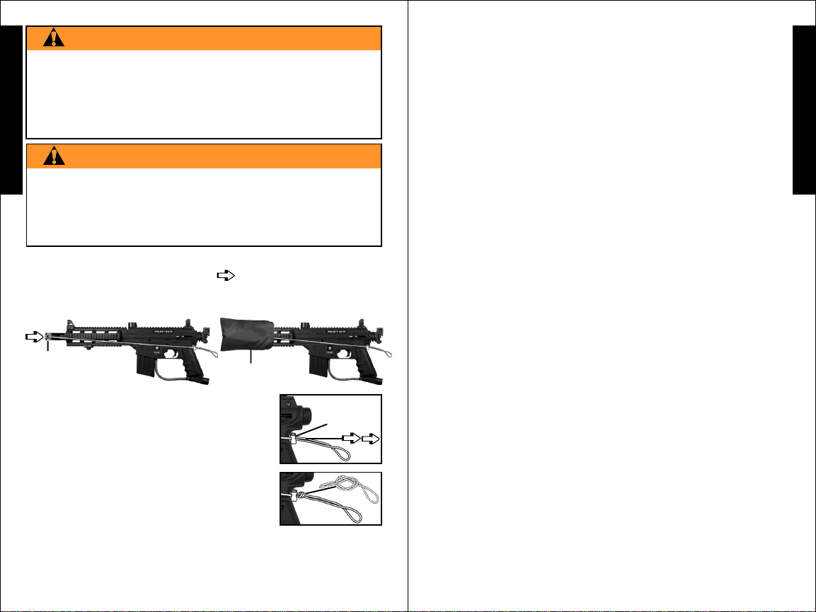
BARREL BLOCKING DEVICE INSTALLATION INSTRUCTIONS
1) Insert the barrel blocking device into the barrel (or over the
barrel, depending on the style of barrel blocking device) and loop
the cord over the top of the receiver and position at the back of the
grip as shown.
Barrel Blocking
Device
2) Adjust the cord length retainer up to the back
of the grip by pulling the cord through it until the
retainer is snug against the back of the grip.
Keeping the cord as tight as possible, leave just
enough cord elasticity to pull the cord/retainer up
over the top of the marker to remove the barrel
blocking device for firing.
3) After the cord length is properly adjusted, lock
the cord length by tying a knot in the cord against
the back of the retainer as shown.
4) Before and after playing, inspect the barrel blocking device and
replace if bag, plug, or cord damage, or loss of cord elasticity is found.
5) Clean the barrel blocking device with plain, warm water and store
out of sunlight in a dry area when not in use.
WARNING
Barrel Blocking
Device
Cord Length
Retainer
2
TM
PROJECT SALVO
2955 Adams Center Road, Fort Wayne, IN 46803 USA
P) 260-749-6022 • F) 260-749-6619 • www.tippmann.com
CONGRATULATIONS on your purchase of a U.S. ARMY Project Salvo
paintball marker. We believe our Project SalvoTM markers to be the most
accurate and durable paintball markers available, and are proudly
manufactured by Tippmann
years of dependable service if cared for properly. Visit
www.usarmypaintball.com and find out how to maximize your paintball
experience – play smart... play strong...Army Strong
Please take time to read this manual thoroughly and become familiar with
your Project Salvo
you attempt to load or fire this marker. If you have a missing or broken
part or need assistance, please contact Tippmann Consumer Relations at
1-800-533-4831 for fast friendly service.
Warning/Caution ..................................................................................... 2
Warning/Caution Barrel Blocking Device Installation............................. 2
Warning/Liability Statement.................................................................... 4
Safety is your Responsibility / Familiarize Yourself With Safety............ 4
Safe Mode = Turning The Safety On (PUSH SAFE) ............................. 4
Fire Mode = Turning The Safety Off (PUSH FIRE)................................ 4
Getting Started ....................................................................................... 6
1. Prepare Marker for Air Supply Cylinder Installation....................... 6
2. Air Supply Cylinder Installation ...................................................... 7
3. Hopper Installation ......................................................................... 8
4. Velocity Adjustment ........................................................................ 8
Specifications.......................................................................................... 9
Schematics ........................................................................................... 10
Unloading Your Marker ......................................................................... 12
Air Supply Cylinder Removal / Air or CO
Repairing Air Supply Leaks .................................................................. 15
Cleaning & Maintenance ...................................................................... 15
Storage ................................................................................................. 15
Marker Disassembly / Assembly .......................................................... 16
Warranty Information, Registration and Repairs.................................. 20
TM
®
. All Project SalvoTM markers will provide many
SM
.
marker’s parts, operation, and safety precautions before
TABLE OF CONTENTS
2 Cylinder Safety Tips...... 12
3
E
N
TM
G
L
I
S
H
Warning/Liability Statement
This marker is classified as a dangerous weapon and is surrendered
E
by Tippmann Sports, LLC with the understanding that the purchaser
assumes all liability resulting from unsafe handling or any action that
N
constitutes a violation of any applicable laws or regulations. Tippmann
G
Sports, LLC shall not be liable for personal injury, loss of property or
life resulting from the use of this weapon under any circumstances,
L
including intentional, reckless, negligent or accidental discharges.
I
All information contained in this manual is subject to change without
S
notice. Tippmann Sports, LLC reserves the right to make changes and
H
improvements to products without incurring any obligation to incorporate
such improvements into products previously sold.
If you as a user do not accept liability, Tippmann Sports, LLC requests
you do not use a Tippmann Sports, LLC marker. By using this paintball
marker you release Tippmann Sports, LLC of any and all liability
associated with its use.
SAFETY IS YOUR RESPONSIBILITY!
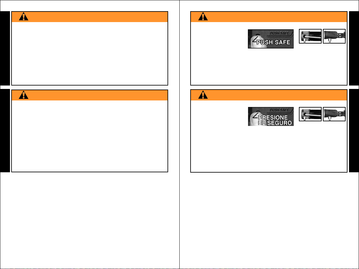
WARNING
• EXCEPT WHEN YOUR MARKER
IS IN USE, ALWAYS MAKE SURE
THAT THE TRIGGER SAFETY IS IN
SAFE MODE, WHICH DISABLES
THE TRIGGER, AND THE BARREL
BLOCKING DEVICE IS INSTALLED
(SEE PAGE 2).
• TO TURN ON THE SAFETY (SAFE MODE): PUSH THE SAFETY
IN AS SHOWN ABOVE.
• TO TURN SAFETY OFF (FIRE MODE): PUSH SAME BUTTON
ON OPPOSITE SIDE OF RECEIVER.
The ownership of this weapon places upon you the total responsibility
for its safe and lawful use. You must observe the same safety
precautions as you would any firearm to assure the safety of not only
yourself but everyone around you. The user should at all times use
caution when using this marker. The sport of Paintball will be viewed
and judged upon your safe and sportsmanlike conduct. Always
TRIGGER SAFETY ACTIVATION
PUSH SAFE
FAMILIARIZE YOURSELF WITH SAFETY...
4
Safety Is Your Responsibility
(continued on page 5)
Safety Is Your Responsibility (continued from page 4)
remember that the game of Paintball can only survive and grow if it
remains SAFE!
• Do not load or fire this marker until you have completely read this
manual and are familiar with its safety features, mechanical operation
and handling characteristics.
• Handle this and any marker as if it were loaded at all times.
• Keep your finger off the trigger until ready to shoot.
• Do not look down the barrel of a paintball marker. Accidental
discharge into the eyes may cause permanent injury or death.
• Keep the trigger safety in safe mode until ready to shoot (see
page 4).
• Keep the barrel blocking device installed on marker when not
shooting (see page 2).
• Never point the marker at anything you do not intend to shoot.
• Never fire your marker at anything you do not intend to shoot because
there may be balls or foreign debris lodged in the chamber, barrel
and / or the marker valve.
• Do not shoot at fragile objects such as windows.
• Never fire your marker at personal property of others. The
paintball impact can cause damage and the paint can stain the
finish of automobiles, houses etc.
• Always keep the muzzle pointed down or in a safe direction, even if
you stumble or fall.
• Eye, face and ear protection designed specifically to stop paintballs
in the form of goggles and full face mask meeting ASTM Specification
F 1776 must be worn by the user and any person within range.
• Never shoot at a person who is not protected by eye, face and ear
protection designed for paintball.
• Pressurize and load the marker only when the marker will be
immediately used.
• NOTE: Before storing or disassembling be sure to remove paintballs
and air supply (see unloading and air supply removal instructions on
page 16), put the trigger safety in the safe mode (see page 4) and
install the barrel blocking device (see page 2).
• Store the marker unloaded and degassed in a secure place.
• Do not field strip or otherwise disassemble this marker while it is
pressurized with air supply.
• Dress appropriately when playing the game of paintball. Avoid
exposing any skin when playing the game of paintball. Even a light
5
Safety Is Your Responsibility
(continued on page 6)
E
N
G
L
I
S
H
Safety Is Your Responsibility (continued from page 5)
layer will absorb some of the impact and protect you from the paintballs.
• Keep exposed skin away from escaping gas when installing or
E
removing air supply cylinder or if the marker or air supply is leaking.
Compressed air, CO
N
cause frostbite under certain conditions.
G
• Use only .68 caliber paintballs, never load or fire any foreign objects.
L
• Avoid alcoholic beverages before and during the use of this marker.
I
Handling markers while under the influence of drugs or alcohol is a
criminal disregard for public safety.
S
• Avoid shooting an opponent at point blank, 6 feet or less.
H
• Familiarize yourself with instructions listed on air supply cylinder or
adaptor. Contact the air supply cylinder or adaptor manufacturer
with any questions.
• Read the Air Supply Cylinder Removal and SAFETY TIPS on pages
12-14 before beginning the cylinder installation.
• Always measure your marker’s velocity before playing paintball and
never shoot at velocities in excess of 300 feet per second (see
instructions on page 8).
2, and nitrogen gasses are very cold and can
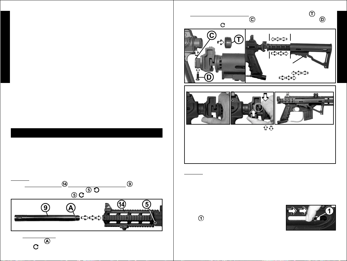
GETTING STARTED: (continued from page 6)
❏ ❏
❏
Install the collapsible stock.
❏ ❏
(slides off),
carefully tighten
TO FOLD THE STOCK / TO UNFOLD THE STOCK:
❏❏
❏
Slide stock up into end cap.
❏❏
.
❏❏
❏
With the end cap cover removed
❏❏
Shorten
Lengthen
Squeeze the
adjustment lever
and slide to shorten
or to lengthen stock.
❏ ❏
❏
Insert bolt and
❏ ❏
LENGTH
ADJUSTMENT:
E
N
G
L
I
S
H
GETTING STARTED
❏
Eye protection designed for paintball use must be worn by the user and
any person within range. Do not disassemble this marker while it is
pressurized with air. Do not pressurize a partially assembled marker.
Read each step completely before performing the step.
Carefully hand start all threaded parts and do not overtighten and
strip threaded parts when assembling.
STEP 1: Prepare Marker for Air Supply Cylinder Installation
❏ ❏
1)
❏
Install the shroud before you install the barrel . To install the
❏ ❏
❏ ❏
❏
shroud:
Replace and tighten the bolt to hold the shroud in place.
❏ ❏
❏
2)
❏ ❏
the barrel o-ring
screw it in
Remove receiver bolt and
❏ ❏
Install the barrel (with the shroud installed): ❏ apply marker oil onto
, insert the barrel into the shroud / receiver and carefully
.
6
❏ ❏
❏
insert the shroud.
❏ ❏
GETTING STARTED:
(continued on page 7)
❏❏
❏
❏❏
1) Grip the stock with
thumb under the
hinge/latch as shown.
4) To unfold: grip the stock with thumb under the hinge/latch. Squeeze
to open latch, turn to unfolded position and release the latch to lock
in place.
STEP 2: Air Supply Cylinder Installation
❏
Y ou must first read the Air Supply Cylinder Removal and SAFETY TIPS
on pages 12-14 before beginning the cylinder installation.
❏ ❏
❏
Do not pressurize a partially assembled paintball marker.
❏ ❏
❏ ❏
❏
First put the trigger safety in Safe Mode
❏ ❏
and
❏ ❏
❏
Next you need to cock the marker by sliding
❏ ❏
the bolt handle all the way back until it locks into
place
position when air supply is attached to the marker .
This will help prevent an accidental discharge.
❏ ❏
❏
To install the air supply cylinder, lubricate the cylinder valve o-ring
❏ ❏
with a little marker oil then insert the cylinder valve end into the air
supply adapter at the back end of the marker grip. Twist the cylinder
2) Squeeze
until the latch
opens.
❏❏
❏
install the barrel blocking device (see instructions on page 2).
❏❏
. Always keep marker in the cocked
7
3) Turn stock to right
side of receiver and
release.
(see instructions on page 4)
Air Supply Cylinder Installation:
(continued on page 8)

Air Supply Cylinder Installation: (continued from page 7)
clockwise into the marker until it stops. Your marker is ready to fire
once you switch to Fire Mode from Safe Mode (see instructions on
page 2). If the tank is full and you do not hear the air supply engage,
E
the pin valve could be too short or the pin valve seal is damaged, follow
N
the Air Supply Cylinder Removal instructions on pages 12-14 and take
G
your air or CO
contact the cylinder manufacturer).
L
STEP 3: Hopper Installation
I
❏ ❏
❏
The barrel blocking device must be installed (see page 2) and the
❏ ❏
S
trigger safety in Safe Mode (see page 4) before filling the hopper.
H
❏ ❏
❏
Make sure that the feed elbow and hopper are clean and free of any
❏ ❏
sharp edges to keep paintballs feeding into the marker smoothly.
❏ ❏
❏
Install the hopper neck into the feed elbow of your marker and tighten
❏ ❏
the hopper down with a 3/16” allen wrench
marker. NOTE: Do not overtighten or the elbow may break.
❏❏
❏
With the trigger safety in Safe Mode and the barrel blocking device
❏❏
installed, you are now ready to load your hopper with paintballs. Fill
the hopper and only remove the barrel blocking device and turn off the
trigger safety when ready to shoot.
2 cylinder to a “C5” Certified Airsmith for inspection or
included with your
Specifications:
PROJECT SALVO
Model ................................................................................ Project Salvo
Caliber .................................................................................................... .68
Action .............................................. Semi-Automatic (open bolt blow-back)
Power/Air Supply ..................................... compressed air, nitrogen or CO
Hopper Capacity ....................................................................200 Paintballs
Ball Feed........................................................................................... Gravity
Cycle Rate ..................................................................... 8 shots per second
Standard Barrel Length ............................................................. 11” / 28 cm
Overall Length (with standard barrel & no tank)28.63 - 32.5” / 72.71 - 82.55 cm
Weight (without tank)........................................................ 3.8 lbs. / 1.72 kg
Effective Range .......................................................... 150+ ft. / 46+ mètres
Velocity.......................................... Always measure your marker’s velocity
before playing paintball and never shoot at velocities in excess of 300 feet
per second (see instructions on page 8).
TM
Marker
E
N
TM
G
L
2
I
S
H
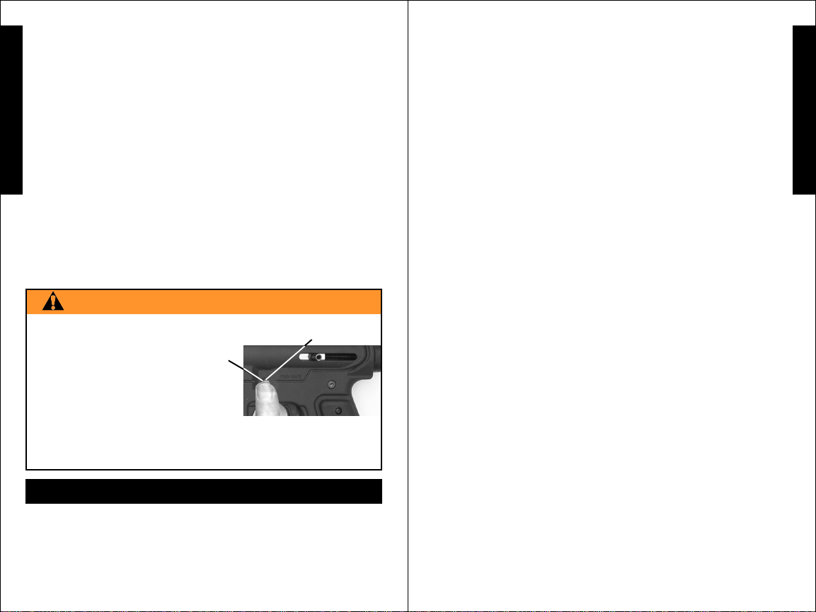
STEP 4: Velocity Adjustment
Each time you play paintball, the velocity
of your paintball marker should be checked
with a chronograph, an instrument for
measuring velocity , prior to playing paintball
to verify that the marker’s velocity is set
below 300 feet per second or less if required
by playing field.
To adjust the velocity use the 3/16” allen wrench included
with your marker. The velocity adjustment screw is located on left
side receiver. To reduce the velocity, turn the screw inward or
clockwise
counterclockwise
. To increase the velocity, turn the screw
. Do not remove the velocity screw.
8
Velocity Adjustment
Screw
3/16” Allen
Wrench
9

PROJECT SALVO
E
N
G
L
I
S
H
TM
Basic Parts List
WARNING
DO NOT DISASSEMBLE THIS MARKER WHILE IT IS PRESSURIZED
WITH AIR. DO NOT PRESSURIZE A PARTIALLY ASSEMBLED MARKER.
www.usarmypaintball.com
Tippmann Service Department
1-800-533-4831
www.tippmann.com
E
N
G
L
I
S
H
10
11

Unloading Your Marker
To unload your marker:
E
be worn by the user and any person within range.
N
❏
Put the trigger safety in Safe Mode (see instructions on page 4) and
1)
❏
install the barrel blocking device (see page 2).
G
❏
Empty and remove the hopper, loosen the hopper bolt and pull the
2)
L
hopper out (at reassembly , do not overtighten bolt or the elbow may break).
I
3) ❏ Go to a designated firing area and remove the barrel blocking device.
S
4) ❏ Point your marker in a safe direction and fire several times to be sure
there are no balls lodged in the chamber and / or barrel. IMPORT ANT: Do not
H
uncock your marker as uncocking your marker may push a ball into the chamber
or down into the barrel in which case the ball will be hidden from view.
❏
Put the trigger safety in Safe Mode (see instructions on page 4) and
5)
❏
Install the barrel blocking device (see page 2).
❏
Visually inspect the chamber for paintballs.
6)
❏
Eye protection designed for paintball use must
Air Supply Cylinder Removal
Step1) ❏ You must first read the following Air Supply Cylinder
WARNINGS and SAFETY TIPS ( before beginning the cylinder removal
in Step 2 on page 14).
WARNING
NEVER UNSCREW THE CYLINDER FROM THE CYLINDER VALVE .
THE BRASS OR NICKEL PLATED VALVE IS
INTENDED TO BE PERMANENTLY ATTACHED TO
THE AIR OR CO2 CYLINDER . AN AIR OR CO2
CYLINDER CAN FLY OFF WITH ENOUGH FORCE
TO CAUSE SERIOUS INJURY OR DEATH IF THE
CYLINDER UNSCREWS FROM A CYLINDER VALVE .
There have been reported incidents that were caused by players
unknowingly unscrewing the cylinder
. This occurs when the player thinks the entire valve-cylinder
assembly is being unscrewed from the air adaptor of the paintball
marker
when in fact they are unscrewing the cylinder from the
cylinder valve . To Avoid This Danger: It is
recommended, if your cylinder is not already
marked, that you use paint or nail polish to
a mark
on the cylinder valve and ❏ place a mark
on the cylinder as shown.
Whenever you turn the cylinder during removal, ❏ watch the
mark
on the cylinder and the mark on th e cylinder valve t o b e
from the cylinder valve
❏
place
Air Supply Cylinder Removal
(continued on page 13)
Air Supply Cylinder Removal: (continued from page 12)
sure that they rotate together. If at any
time these marks start to separate as
shown
, the cylinder is starting
to unscrew from the cylinder valve
and you should STOP and take the
entire unit to a “C5” certified airsmith
for safe removal and/or repair.
NOTE:
The cylinder valve should unscrew
from the paintball marker in about 3 or 4 full turns. If you finish
the 4th full turn and the cylinder valve is not unscrewed from the
paintball marker, STOP! Take the entire unit to a “C5” certified
❏
airsmith for safe removal and/or repair.
Locate a “C5” Certified
STOP
E
N
G
L
I
S
H
Airsmith at www.paintball-pti.com/search.asp
Whether you have a new or used refillable Air or CO2 cylinder, you
are at risk if any of the following has occurred:
was replaced or altered after purchase.
was installed.
for any reason.
or CO
2 cylinder. If any of these conditions has occurred take
❏
The valve unit was removed from the cylinder
❏
Any modification was done to the refillable Air
❏
❏
The valve unit
An anti-siphon device
your air or CO2 cylinder to a “C5” Certified Airsmith for inspection
or contact the cylinder manufacturer.
SAFETY TIPS to ensure that your Air or CO2 cylinder is safe
for play:
•Improper use, filling, storage or disposal of Air or CO
2 cylinder may
result in property damage, serious personal injury or death.
•Make sure that any maintenance or modification to any Air or CO
2
cylinder is done by a qualified professional, such as a “C5”
certified airsmith.
•The use of anti-siphon devices is not recommended. However, if one
is already installed on your Air or CO
2 cylinder or is desired, it is critical
that your cylinder be checked by , or the device installed by , a qualified
professional.
• All Air or CO
2 cylinders must be filled only by properly trained personnel.
•Cylinder valves must be installed only by properly trained personnel.
•Do not overfill!! Never exceed the Air or CO
•Do not expose pressurized Air or CO
2 cylinder ’s capacity.
2 cylinder to temperatures
exceeding 130 degrees Fahrenheit ( 55 degrees Celsius ).
•Do not use caustic cleaners or strippers on the Air or CO
2 cylinder or
tank valve and do not expose to corrosive materials.
•Do not modify the Air or CO
disassemble the tank valve from the Air or CO
2 cylinder in any way. Never try to
1312
2 cylinder.
Air Supply Cylinder Removal
(continued on page 14)

Air Supply Cylinder Removal: (continued from page 13)
•Any Air or CO
temperature of 250 degrees Fahrenheit ( 121 degrees Celsius )
E
or more must be destroyed by properly trained personnel.
• Use appropriate gas for your cylinder. Only use CO
N
cylinder and only use compressed air in a compressed air cylinder.
G
•Keep all cylinders out of the reach of children.
•The Air or CO
L
retested at least every 5 years by a DOT licensed agency.
I
❏
Locate a “C5” Certified Airsmith at
S
www.paintball-pti.com/search.asp
2 cylinder that has been exposed to fire or heated to a
2 in a CO2
2 cylinder should be inspected and hydrostatically
H
WARNING
KEEP EXPOSED SKIN AWAY FROM ESCAPING GAS WHEN INSTALLING
OR REMOVING AIR SUPPLY OR IF THE MARKER OR AIR SUPPLY IS
LEAKING. COMPRESSED AIR, CO2, AND NITROGEN GASSES ARE VERY
COLD AND CAN CAUSE FROSTBITE UNDER CERTAIN CONDITIONS.
Step 2:
designed for paintball use must be worn by the user and any person
within range.
page 12).
Step 3: Watch the marks on the cylinder and cylinder valve as you
❏
This allows the air supply pin valve to close so that no air will enter
the marker.
remaining gas in the marker by pulling the trigger until the marker
stops firing (this may take 4-5 shots).
the tank pin valve has not closed yet (the tank pin valve could be too
long, because of the variances in tank pin valve parts, each tank
varies slightly on exactly how far it should be turned) and
have to turn the tank counterclockwise
this step until the marker does not fire,
NOTE: If during this step, you turned the tank and it began to leak
before you pulled the trigger, the tank o-ring should be checked for
damage before reassembly (see Repairing Air Supply Cylinder
Leaks on page 15).
Step 4:
safe direction until stored air is completely discharged. NOTE: Before
storing or disassembling be sure to follow
and
18).
barrel blocking device (see page 2).
To remove a charged air supply cylinder:
❏
Unload Your Marker (follow the instructions on
Turn the cylinder approximately 3/4 of a turn counterclockwise .
❏
Point the marker in a safe direction and discharge the
If your marker continues to fire,
a little further and repeat
❏
After air cylinder is removed, ❏ point & fire the marker in a
❏
Air Supply Cylinder Removal instructions (see pages 16-
❏
Put the trigger safety in safe mode (see page 4) and Install the
❏
Eye protection
❏
you will
then remove the tank.
❏
Unloading Your Marker
Repairing Air Supply Cylinder Leaks:
The most common leak occurs from a bad air supply valve o-ring. To replace
a valve o-ring you must first remove the bad o-ring then install a new one
and lubricate with a few drops of oil. This o-ring is located on the tip of
your air supply valve. The best valve o-rings are made of urethane.
Urethane o-rings are not affected by high air supply pressures. These
may be purchased from Tippmann
NOTE: If new valve o-ring does not resolve air supply leak, do not
attempt to repair air supply cylinder. Contact Tippmann Sports, LLC,
your local paintball dealer or a “C5” Certified Airsmith.
®
or your local paintball dealer.
Cleaning & Maintenance
❏
Eye protection must be worn during disassembly / assembly. To
reduce the chance of accidental discharge: First follow
Y our Marker and
16-18. Do not disassemble this marker while it is pressurized with air.
Do not pressurize a partially assembled marker.
• Follow warnings listed on the air supply cylinder for handling and storage.
• Familiarize yourself with instructions listed on air supply cylinder or
adaptor. Contact the air supply cylinder or adaptor manufacturer with
any questions.
• Do not use any petroleum based cleaning solvents.
• Do not use any cleaning solvents that come in aerosol cans. NOTE:
Petroleum based products and aerosol products can damage your
markers’ o-rings.
• To clean your paintball marker use a damp towel with water to wipe off
paint, oil, and debris. Use Tippmann
marker oil to maintain your marker in good working condition.
•To clean inside the barrel. Depress the feed elbow
lock
squeegee into the breech, then pull the squeegee
through the barrel to remove debris.
• Inspect and lubricate the internal drive assembly parts:
❏
the front bolt o-ring, ❏ the rear bolt o-ring, ❏ the linkage arm
❏
the drive spring / guide pin (see Marker Disassembly / Assembly,
and
internal parts removal and installation instructions on pages 16-19).
• Inspect and lubricate the barrel o-ring and the air supply valve
o-ring with a few drops of oil.
❏
Air Supply Cylinder Removal instructions on pages
®
marker oil or other premium
and tip out feed elbow . Insert the cable
❏
Unloading
E
N
G
L
I
S
H
Storage
Before storage ❏ unload and ❏ remove air supply (follow instructions on
pages 12-14).
❏
Put the trigger safety in Safe Mode (see page 4) and
1514
Storage: (continued on page 16)

Storage: (continued from page 15)
install the barrel blocking device (see page 2). You should store your
marker in a dry area. Before storing your marker make sure that the
marker is cleaned and oiled (see cleaning and maintenance on page
E
19) so that it does not rust. Store your marker with the bolt in the
N
forward position, uncocked (see below).
G
❏
When removing your marker out of storage make sure the trigger safety
L
is in Safe Mode (see page 4) and the barrel blocking device is installed
(see page 2). Y ou should re-oil the rear bolt o-ring and the front bolt o-ring
I
before use (see cleaning and maintenance on page 15).
S
Marker Disassembly / Assembly
H
❏
Eye protection designed for paintball use must be worn by the user
and any person within range during disassembly / assembly.
❏
First follow
Removal instructions on pages 12-14. Do not disassemble a pressurized
paintball marker. Do not pressurize a partially
assembled paintball marker.
❏
Put the marker into the uncocked position.
To uncock the marker: Pull and hold the bolt
cocking handle
trigger and release the handle slowly forward
which will uncock the marker.
NOTE: Carefully hand start all threaded parts and do not overtighten and
strip threaded parts when assembling.
TA06209 Collapsible Stock Assembly
(Replaces End Cap Cover )
TA09919
Bolt
Collapsible Stock Assembly not
Shown In basic parts pages 10-11).
Unloading Your Marker and ❏ Air Supply Cylinder
back - then pull the
NOTE: (if 2 adapter bolts are
removed, the short bolt goes in front
when reassembling).
Marker Disassembly (continued on page 17)
16
Marker Disassembly (continued from page 16)
❏
Remove the barrel unscrew .
press the 2 tabs
until it stops.
elbow
the receiver.
❏
unscrew bolt and slide off. ❏ Unscrew the 6 receiver connection
bolts ( 3 long receiver to access the internal parts.
❏
and drive spring (these parts must be removed before the bolt handle
can be removed). Disconnect the linkage arm from the rear and front
bolts. Slide the front bolt off the power tube and check the o-ring.
Clean and oil the o-ring or if damaged, replace with a new one. Do the
same with the rear bolt o-ring.
Power tube and valve removal.
NOTE: Do not remove the gas line fitting unless it is leaking or you need
to replace the valve. If you should do so you will need some teflon tape or
paste to reinstall it. Carefully hand start all threaded parts and do not
overtighten and strip threaded parts when assembling.
❏
❏
and valve, unscrew
bolts
❏
use a wrench (
fitting is out, the valve will slide out the back of the power tube.
NOTE:
with a new one. If the o-ring is damaged your marker will not function
correctly.
❏
valve into the power tube and align the holes of the valve and
power tube.
fitting and carefully screw it into the valve and snug with a wrench
off any excess paste.
❏
power tube and the right receiver half, apply red loctite #271 sealant to
threads of two valve lock bolts
tighten bolts and strip threads.
, press the feed lock , tilt the feed elbow out and slide it of f
To remove the left-side receiver : ❏ Remove the rear sight
With left half removed, pull the end cap out to remove the guide pin
First, complete Marker Disassembly Instructions (see page 20).
Power tube removal: To remove the power tube
from the right side receiver.
Valve removal from power tube: If it is necessary to remove the valve,
❏
Check the external valve o-ring and if damaged, replace
❏
Reinstall the valve into the power tube: Insert cleaned and oiled
(do not over tighten and strip threaded parts).
Reinstall the power tube/valve into receiver: align the holes of the
in and slide it out. ❏ Turn the velocity screw in
❏
Loosen the 2 adapter bolts . ❏ Remove the feed
) + (3 short - ). Then carefully lift the left-side
the two valve lock
) to slowly unscrew the gas line fitting. Once the
Clean all parts and oil the o-rings.
❏
Apply teflon tape or paste on threads of gas line
❏
Remove the magazine ,
❏
Wipe
and attach - do not over
❏
Wipe off any excess paste.
17
Marker Disassembly / Assembly
(continued on page 18)
E
N
G
L
I
S
H

Marker Disassembly / Assembly (continued from page 17)
Reassembling Receiver Halves:
STEP 1: ❏ Double check that the Trigger Assembly ( ❏ Trigger Spring
E
/ ❏ Safety / ❏ Pins (4) / ❏ Trigger / ❏ Sear / ❏ Sear
Spring*
N
G
; ❏ Linkage Arm* ; ❏ Link Arm Pins (2) ; ❏ Rear Bolt* +
L
Bolt Insert ; ❏ Bolt Handle ; ❏ Drive Spring* + ❏ Guide
Pin*
I
; ❏ 2 Tank Adapter Nuts ; are in place and (*=oiled) (see schematics
S
on pages 10-11 for details as needed).
H
/ ❏ Sear Pin* (black) ) ; and other parts: ❏ Front Sight
+ ❏ Pin* + ❏ Spring* ; ❏ Front Bolt* ; ❏ Ball Latch
; ❏ Buffer O-ring ; ❏ End Cap + ❏ End Cap Cover
Carefully hand start all
threaded parts and do
not overtighten and
strip threaded parts
when assembling.
Reassembling Receiver Halves: (continued from page 18)
❏
Press in the 2 magazine tabs and slide the
magazine
it in place. NOTE: The magazine may be used to
store tools and lubricating oil for your marker (shown
with 2 allen wrenches
❏
up into the marker until the tabs lock
and oil).
E
N
G
L
I
S
H
STEP 2: ❏ Carefully install the left receiver half (make sure halves fit flush).
❏
Insert 3 short receiver bolts .
❏
If marker has a barrel shroud - insert it now.
❏
Insert 3 long receiver bolts and ❏ tighten the 6 bolts / .
❏
Attach adapter tighten 2 bolts (NOTE: short adapter
bolt goes in front).
the barrel
❏
Slide the feed elbow into the receiver and tilt up until the front sight
holds it in place.
❏
Slide the rear sight on, insert bolt and tighten .
❏
and carefully screw it in.
Apply marker oil onto the barrel o-ring, insert
18
Reassembling Receiver Halves:
(continued on page 19)
19

W ARRANTY AND REPAIR INFORMATION
E
TIPPMANN SPORTS, LLC ("Tippmann") is dedicated to quality paintball
products and outstanding service. In the unlikely event of a problem with
N
this Tippmann paintball marker ("Marker") and/or Tippmann accessories
G
("Accessories"), Tippmann's customer service personnel are available to
assist you. For customer service and/or other information, please contact:
L
I
S
H
Tippmann Sports, LLC
2955 Adams Center Road
Fort Wayne, IN 46803
www.tippmann.com
1-800-533-4831
WARRANTY REGISTRATION
T o activate the Marker's Limited W arranty , you must register the Marker within
thirty (30) days of the date of original retail sale by:
1. Registering online at
2. Completing the attached warranty registration card and returning it to
Tippmann at the address above.
The Limited Warranty for T ippmann Accessories does not require activation
or registration; by registering the Marker, you activate the warranty for the
Accessories.
www.tippmann.com; or
LIMITED WARRANTY
Tippmann warrants to the original purchaser that it will make any repairs or
replacements necessary to correct defects in material or workmanship, at
no charge to you, for the Marker for a period of one (1) year from the date of
original retail sale. Further, Tippmann warrants to the original purchaser
that it will make any repairs or replacements necessary to correct defects in
material or workmanship, at no charge to you, for Tippmann Accessories for
a period of ninety (90) days from the date of original retail sale. All Tippmann
asks is that you properly maintain and care for the Marker and Accessories
(collectively , the "Product") and that you have warranty repairs performed by
Tippmann or a T ippmann Certified Tech Center.
This Limited Warranty is non-transferable, and it does not cover damage or
defects to the Product caused by (a) improper maintenance; (b) alteration or
modification; (c) unauthorized repair; (d) accident; (e) abuse or misuse; (f)
neglect or negligence; and/or (g) normal wear and tear.
Tippmann does not authorize any person or representative to assume or
grant any other warranty obligation with the sale of this Product.
THIS IS THE ONL Y EXPRESS W ARRANTY GIVEN WITH THE PURCHASE
OF THIS PRODUCT; ANY AND ALL OTHER EXPRESS W ARRANTIES ARE
WARRANTY AND REPAIR INFORMATION:
(continued on page 21)
WARRANTY AND REPAIR INFORMATION: (continued from page 20)
DISCLAIMED. THE IMPLIED W ARRANTIES OF MERCHANT ABILITY AND
FITNESS FOR A PARTICULAR PURPOSE ARE LIMITED TO THE
APPLICABLE LIMITED WARRANTY PERIOD SET FORTH HEREIN, AND
NO WARRANTIES, WHETHER EXPRESS OR IMPLIED, SHALL APPLY
AFTER EXPIRATION OF SUCH PERIOD.
Some states and nations do not allow limitations on the duration of implied
warranties, so the above limitation may not apply to you.
The sole and exclusive liability of Tippmann and/or its authorized dealers
under this Limited Warranty shall be for the repair or replacement of any
part or assembly determined to be defective in material or workmanship.
TIPPMANN SHALL NOT BE LIABLE FOR, AND YOU EXPRESSLY
DISCLAIM, ANY DIRECT , INDIRECT, CONSEQUENTIAL OR INCIDENTAL
DAMAGES (COLLECTIVEL Y, "DAMAGES") ARISING OUT O F THE SALE
OR USE OF , OR YOUR INABILITY TO USE, THE PRODUCT . NO PAYMENT
OR OTHER COMPENSATION WILL BE MADE FOR DAMAGES,
INCLUDING INJURY TO PERSON OR PROPERTY OR LOSS OF
REVENUE WHICH MIGHT BE PAID, INCURRED OR SUSTAINED BY
REASON OF THE FAILURE OF ANY PART OR ASSEMBLY OF THE
PRODUCT.
Some states and nations do not allow the exclusion or limitation of incidental
or consequential damages, so the above limitation or exclusion may not
apply to you. This warranty gives you specific legal rights, and you may also
have other rights that may vary from state to state or nation to nation.
E
N
G
L
I
S
H
W ARRANTY AND NON-W ARRANTY REPAIRS
When shipping the Product to Tippmann for warranty or non-warranty repair:
(1) If you have aftermarket parts on your Marker, please test the Marker with
original stock parts before returning the Marker for service or repair.
(2) Always unload and remove the air supply from the Marker. Do not ship
the air supply tank if it is not completely empty.
(3) Ship the Product to the Tippmann address identified above.
(4) You must pre-pay postage and delivery charges.
(5) Provide the date of purchase for the Product.
(6) Briefly describe the repair requested.
(7) Include your name, return address and a telephone number where you
can be reached during normal business hours, if possible.
Tippmann makes every effort to complete its repair work within twenty-four
(24) hours of receipt. Tippmann will return the Product to you via regular
ground UPS. If you wish to have it returned using a faster service, you can
request NEXT DAY AIR UPS OR SECOND DAY AIR UPS, but you will be
charged for this service and must include your credit card number with the
expiration date. Your credit card will be charged the difference in additional
cost over regular ground shipping service.
2120

®
TIPPMANN
2955 ADAMS CENTER ROAD
FT. WAYNE, IN 46803 USA
Model: ❏
Serial Number (above left front grip).
Project Salvo
TM
Warranty Registration online at www.tippmann.com
or complete this warranty card and mail to Tippmann
#
Purchased from Date
THIS PAGE INTENTIONALLY LEFT BLANK.
®
.
City State Zip
Country
Your Name (print)
Address
City State Zip
Country
E-mail
Phone #
Age
Male
Female

País
Pays
Courriel
Dirección
Ciudad Estado Código Postal
Adresse
Ville État Code Postal
Pays
Ville État Code Postal
País
Nombre (letra de molde)
Votre nom
Nombre comprador Fecha
Ciudad Estado Código Postal
Acheté chez Date
Número de Serie (Número sobre el mango delantero izquierdo).
Modèle / Modelo: ❏
Numéro de Série (au-dessus du grip avant gauche).
TIPPMANN
2955 ADAMS CENTER ROAD
FT. WAYNE, IN 46803 USA
Project Salvo
INSIDE BACK COVER
Teléfono
Téléphone
Edad
Âge
Hombre
Homme
Mujer
Femme
TM
esta tarjeta de garantía y enviela por correo regular a Tippmann
®
Registro de Garantia via On line a www.tippmann.com o complete
ou bien remplissez cette carte de garantie et envoyez-la à Tippmann
Enregistrement de la garantie en ligne sur www.tippmann.com
#
®
.
®
.
 Loading...