

Page 1

THURLBY THANDAR INSTRUMENTS
INSTRUCTION MANUAL
TSX Series
Programmable High Current DC Power Supplies
Page 2

Table of Contents
Specification 3
Safety 5
EMC 6
Installation 7
Manual Operation 8
Maintenance and Repair 11
Remote Operation 12
ARC Interface 13
Remote Commands 22
Instructions en Francais
Sécurité 34
Montage 35
Fonctionnement manuel 36
Entretien et Réparations 40
Fonctionnement à distance 41
Commandes à distance 52
Bedienungsanleitung auf Deutsch
Sicherheit 64
Installation 65
Handbedienung 66
Wartung und Instandsetzung 70
Fernbetrieb 71
Fernbefehle 82
1
Page 3

EC Declaration of Conformity
We Thurlby Thandar Instruments Ltd
Glebe Road
Huntingdon
Cambridgeshire PE29 7DR
England
declare that the
TSX3510P & TSX1820P Programmable Power Supplies
meet the intent of the EMC Directive 2004/108/EC and the Low Voltage Directive 2006/95/EC.
Compliance was demonstrated by conformance to the following specifications which have been
listed in the Official Journal of the European Communities.
EMC
Emissions: a) EN61326-1 (2006) Radiated, Class B
b) EN61326-1 (2006) Conducted, Class B
c) EN61326-1 (2006) Harmonics, referring to EN61000-3-2 (2006)
Immunity: EN61326-1 (2006) Immunity Table 1, referring to:
a) EN61000-4-2 (1995) Electrostatic Discharge
b) EN61000-4-3 (2006) Electromagnetic Field
c) EN61000-4-11 (2004) Voltage Interrupt
d) EN61000-4-4 (2004) Fast Transient
e) EN61000-4-5 (2006) Surge
f) EN61000-4-6 (2007) Conducted RF
Performance levels achieved are detailed in the user manual.
Safety
EN61010-1 Installation Category II, Pollution Degree 2.
2
CHRIS WILDING
TECHNICAL DIRECTOR
2 May 2009
Page 4

Specification
OUTPUT SPECIFICATIONS
Output Voltage Range: 0V to 35.3V (35V/10A); 0V to 18.15V (18V/20A).
Output Current Range: 0.01A to 10.2A (35V/10A); 0.01A to 20.2A (18V/20A).
Output Voltage Setting: Direct keyboard entry or quasi-analogue rotary control; setting
resolution 10mV.
Output Current Setting: Direct keyboard entry or quasi-analogue rotary control; setting
resolution 10mA.
Output Mode: Constant voltage or constant current with automatic crossover.
Output Switch: Electronic. Preset voltage and current displayed when off.
Output Terminals: 4mm terminals on front panel, screw terminals at rear.
Sensing: Remote via rear panel screw terminals or direct via shorting strip
(supplied).
Output Impedance:
Output Protection: Forward protection by Over-Voltage-Protection (OVP) trip;
OVP Setting: Direct keyboard entry.
OVP Range: 1V to 40V (35V/10A); 1V to 25V (18V/20A).
OVP Delay: <200µs
Load & Line Regulation: <0.01% of maximum output for 90% load change or 10% line
Ripple & Noise: <1mV rms typical in constant voltage.
HF Common Mode Noise: Typically <3mV rms, <10mV peak.
Transient Response: 20µs to within 50mV of setting for 90% load change.
Temperature Coefficient: typically <100 ppm/°C.
Protection Functions: Overvoltage trip; regulator overtemperature; sense miswiring.
Status Indication: Output off lamp; constant voltage mode lamp;
<1mΩ in constant voltage mode.
>5kΩ in constant current mode (voltage limit at max.).
maximum voltage that should be applied to the terminals is 50V.
Reverse protection by diode clamp for reverse currents up to 3A.
change.
<3mA rms typical in constant current.
constant current mode lamp; trip message on display.
METER SPECIFICATIONS
Meter Types: Dual 4 digit meters with 12·5mm (0.5") LEDs. Reading rate 4Hz.
Meter Resolution: 10mV, 10mA
Meter Accuracy: Voltage 0.2% of reading ± 1 digit, current 0.5% of reading ± 1 digit.
KEYBOARD FUNCTIONS
Delta Mode: Increase or decrease voltage or current in user-selectable steps.
Store/Recall: Store and recall voltage, current and OVP levels from non-volatile
memory (25 memories).
Interface Selection: Set digital interface type (RS232 or GPIB), baud rate and address.
3
Page 5

Note: All voltage and current levels set via the keyboard are displayed on a separate 0·3” 4-digit
display. This entry preview system ensures that the user can observe the value entered before it
is effected thus avoiding possible error. The display is also used for setting additional functions.
When the output switch is on and no other function is selected, the display shows output power in
Watts.
DIGITAL INTERFACES
Operational Functions: Set voltage, set current, set OVP; set output on/off; read output
voltage; read output current; read output power.
RS232: Variable baud rate, 9600 baud maximum, 9 pin D-connector (female).
Fully compatible with ARC (Addressable RS232 Chain) system.
GPIB: Conforming with IEEE488.1 and IEEE488.2.
OUTPUT SPECIFICATIONS - REMOTE OPERATION
Output Voltage Setting: 12 bit resolution (10mV steps).
Output Current Setting: 12 bit resolution (10mA steps).
Setting Accuracy: Voltage: ±(0·1% + 10mV); Current: ± (0.2% + 20mA)
Output Switch: Electronic by interface command.
Readback Resolution: Voltage: 10mV over the entire range.
Current: 10mA over the entire range.
Readback Accuracy: Voltage: ± (0.2% of reading + 1 digit);
Current: ± (0.5% of reading + 1 digit).
RESPONSE TIME OVER RS232/GPIB:
Interface: <15ms (single command, buffer empty).
Power Supply: An internal time constant, T, (typically 22ms) governs the settling time
of a step voltage increase. Settling time to within 1% of the step
change = 4.6T, to 0.1% = 6.9T, to 0.01% = 9.2T; for example, after a
10V step the output will be within 1 digit (10mV = 0.1%) of its new
value in typically 150ms. For load current of 1 Amp or more, settling
times for downward steps will be very similar; however, response
times will be longer at low loads.
GENERAL
AC Input Voltage: 110V-120V AC or 220V-240V AC ±10%, 50/60Hz.
Installation Category II.
Power Consumption: 600VA max.
Operating Range: 5°C to +40°C, 20% to 80% RH.
Storage Range: –40°C to +70°C.
Environmental: Indoor use at altitudes up to 2000m, Pollution Degree 2.
4
Size: 200 x 140 x 385mm (WxHxD); half rack width x 3U height;
(optional rack mounting kit available)
Weight: 5.5kg.
Safety: Complies with EN61010-1
EMC: Complies with EN61326-1
Page 6

Safety
This power supply is a Safety Class I instrument according to IEC classification and has been
designed to meet the requirements of EN61010-1 (Safety Requirements for Electrical Equipment
for Measurement, Control and Laboratory Use). It is an Installation Category II instrument
intended for operation from a normal single phase supply.
This instrument has been tested in accordance with EN61010-1 and has been supplied in a safe
condition. This instruction manual contains some information and warnings which have to be
followed by the user to ensure safe operation and to retain the instrument in a safe condition.
This instrument has been designed for indoor use in a Pollution Degree 2 environment in the
temperature range 5°C to 40°C, 20% - 80% RH (non-condensing). It may occasionally be
subjected to temperatures between +5°C and –10°C without degradation of its safety. Do not
operate while condensation is present.
Use of this instrument in a manner not specified by these instructions may impair the safety
protection provided. Do not operate the instrument outside its rated supply voltages or
environmental range.
WARNING! THIS INSTRUMENT MUST BE EARTHED
Any interruption of the mains earth conductor inside or outside the instrument will make the
instrument dangerous. Intentional interruption is prohibited. The protective action must not be
negated by the use of an extension cord without a protective conductor.
When the instrument is connected to its supply, terminals may be live and opening the covers or
removal of parts (except those to which access can be gained by hand) is likely to expose live
parts. The apparatus shall be disconnected from all voltage sources before it is opened for any
adjustment, replacement, maintenance or repair. Capacitors inside the power supply may still be
charged even if the power supply has been disconnected from all voltage sources but will be
safely discharged about 10 minutes after switching off power.
Any adjustment, maintenance and repair of the opened instrument under voltage shall be avoided
as far as possible and, if inevitable, shall be carried out only by a skilled person who is aware of
the hazard involved.
This instrument uses a Lithium button cell for non-volatile memory battery back-up; typical life is 5
years. In the event of replacement becoming necessary, replace only with a cell of the correct
type, i.e. 3V Li/Mn0
in accordance with local regulations; do not cut open, incinerate, expose to temperatures above
60°C or attempt to recharge.
If the instrument is clearly defective, has been subject to mechanical damage, excessive moisture
or chemical corrosion the safety protection may be impaired and the apparatus should be
withdrawn from use and returned for checking and repair.
Make sure that only fuses with the required rated current and of the specified type are used for
replacement. The use of makeshift fuses and the short-circuiting of fuse holders is prohibited. Do
not wet the instrument when cleaning it.
The following symbols are used on the instrument and in this manual:-
20mm button cell type 2032. Exhausted cells must be disposed of carefully
2
l
5
Earth (ground) terminal.
mains supply OFF.
mains supply ON.
alternating current (ac)
direct current (dc)
Page 7

This instrument has been designed to meet the requirements of the EMC Directive 2004/108/EC.
Compliance was demonstrated by meeting the test limits of the following standards:
Emissions
EN61326-1 (2006) EMC product standard for Electrical Equipment for Measurement, Control and
Laboratory Use. Test limits used were:
a) Radiated: Class B
b) Conducted: Class B
c) Harmonics: EN61000-3-2 (2006) Class A; the instrument is Class A by product category.
Immunity
EN61326-1 (2006) EMC product standard for Electrical Equipment for Measurement, Control and
Laboratory Use.
Test methods, limits and performance achieved are shown below (requirement shown in
brackets):
a) EN61000-4-2 (1995) Electrostatic Discharge : 4kV air, 4kV contact, Performance A (B).
EMC
b) EN61000-4-3 (2006) Electromagnetic Field:
3V/m, 80% AM at 1kHz, 80MHz – 1GHz: Performance A (A) and 1.4GHz to 2GHz:
Performance A (A); 1V/m, 2.0GHz to 2.7GHz: Performance A (A).
c) EN61000-4-11 (2004) Voltage Interrupt: ½ cycle and 1 cycle, 0%: Performance A (B);
25 cycles, 70%: Performance A (C); 250 cycles, 0%: Performance C (C).
d) EN61000-4-4 (2004) Fast Transient, 1kV peak (AC line), 0·5kV peak (DC Outputs),
Performance A (B).
e) EN61000-4-5 (2006) Surge, 0·5kV (line to line), 1kV (line to ground), Performance A (B).
f) EN61000-4-6 (2007) Conducted RF, 3V, 80% AM at 1kHz (AC line only; DC Output
connections <3m, therefore not tested), Performance A (A).
According to EN61326-1 the definitions of performance criteria are:
Performance criterion A: ‘During test normal performance within the specification limits.’
Performance criterion B: ‘During test, temporary degradation, or loss of function or
performance which is self-recovering’.
Performance criterion C: ‘During test, temporary degradation, or loss of function or
performance which requires operator intervention or system reset occurs.’
Note that if operation in a high RF field is unavoidable it is good practice to connect the PSU to
the target system using screened leads which have been passed (together) through an absorbing
ferrite sleeve fitted close to the PSU terminals.
Cautions
To ensure continued compliance with the EMC directive observe the following precautions:
a) After opening the case for any reason ensure that all signal and ground connections are
b) In the event of part replacement becoming necessary, only use components of an identical
6
remade correctly and that case screws are correctly refitted and tightened.
type, see the Service Manual.
Page 8
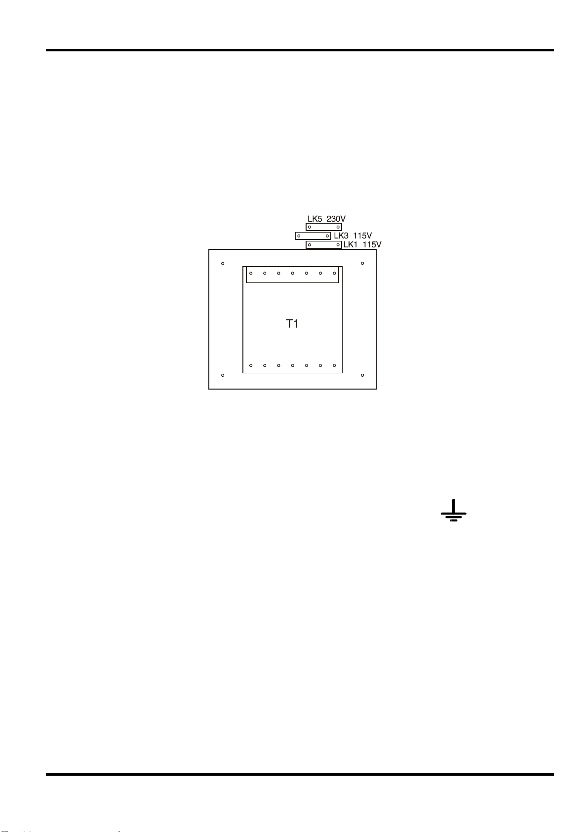
Mains Operating Voltage
Check that the instrument operating voltage marked on the rear panel is suitable for the local
supply. Should it be necessary to change the operating voltage, proceed as follows:
1. Ensure that the instrument is disconnected from the AC supply.
2. Remove the 6 screws holding the case upper and lift off the cover.
3. Change the appropriate zero-ohm links beside the transformer on the pcb:
Link LK5 only for 230V operation
Link LK1 and LK3 only for 115V operation
Installation
4. Re-assemble in the reverse order.
5. To comply with safety standard requirements the operating voltage on the rear panel must be
changed to clearly show the new voltage setting.
Mains Lead
When a three core mains lead with bare ends is provided this should be connected as follows:
GREEN/YELLOW - EARTH
Safety Earth Symbol
When fitting a fused plug a 5 amp fuse should be fitted inside the plug. As the colours of the
wires in the mains lead of this apparatus may not correspond with the coloured markings
identifying the terminals in your plug proceed as follows:
The wire which is coloured green-and-yellow must be connected to the terminal in the plug which
is marked by the letter E or by the safety earth symbol shown above or coloured green or greenand-yellow.
The wire which is coloured blue must be connected to the terminal which is marked with the letter
N or coloured black.
The wire which is coloured brown must be connected to the terminal which is marked with the
letter L or coloured red.
BROWN - MAINS LIVE
BLUE - MAINS NEUTRAL
WARNING! THIS APPARATUS MUST BE EARTHED.
Any interruption of the protective conductor inside or outside the apparatus or disconnection of
the protective earth terminal is likely to make the apparatus dangerous. Intentional interruption is
prohibited.
7
Page 9

Front Panel
The POWER switch is used to apply line voltage to the instrument. When switched to on (l) the
instrument will be powered and the start-up procedure will be executed; this will take
approximately 5 second to complete. If all is well the settings from the last power-down will be
installed and the instrument will be ready for use.
The output terminals are located on the right of the front panel. The red terminal is positive and
the black terminal is negative. Connection to the output terminals can be made with any of the
following: 4mm plugs, spade terminals or wire ends. To minimise voltage drop, the connecting
leads to the load should be of an adequate wire gauge and be kept short. The output terminals
are duplicated on the rear panel, together with the sense terminals.
The keyboard is located to the left of the output terminals. This consists of 27 keys and a LED
indicating the instrument output status. The use of the keyboard to control all instrument functions
is discussed in the following sections.
To the left of the keyboard is the status display which consists of a 4-digit, 7-segment display and
10 LEDs. Normally the status display will show the output power (in Watts) when the output is on
or will be blank when the output is off; however, other information will appear when selections are
made from the keyboard. The relevant annunciator LED will indicate what the contents of the
display represent at any time.
Manual Operation
Above the keyboard are the main displays and LED indicators which show the conditions of the
output. The displays show the set voltage and set current when the output is off and the voltage
at the output terminals and output current when the output is on.
To the right of the LED indicators is a continuously rotating control which may be used to make
fine adjustments to voltage or current as described later.
General Principles of Manual Operation
The following sections explain in detail the use of the keyboard to control all instrument functions.
If an error is encountered during keyboard operation the status display will show Ennn where nnn
is a decimal number. A full list of possible errors is given in the STATUS REPORTING section.
Set Voltage
The set voltage is normally shown in the top left hand display marked V. The exception to this is
when the output is on and in constant current (CI) mode. In this case the actual output voltage will
be less than the set value and will be shown instead.
To set the voltage press the VOLTS key. The status display will show the set voltage value and
the VOLTS LED will light. A new value may now be entered from the numeric keypad. The value
will be in Volts and the POINT key may be used to enter decimal digits. Once the required value
is entered press the CONFIRM key and the set voltage will be updated immediately. To exit
without making any changes press the ESCAPE key. If a mistake is made during entry press the
VOLTS key and start again. The maximum and minimum values accepted will depend on the
particular model, see the specification section for details.
Set Current
When the output is off the set current is shown in the top right hand display marked A. When the
output is on and in constant voltage (CV) mode the output current is shown. When in constant
current (CI) mode the output current is equal to the set current and this is shown.
To set the current press the AMPS key. The status display will show the set current value and the
AMPS LED will light. A new value may now be entered from the numeric keypad. The value will
be in Amps and the POINT key may be used to enter decimal digits.
8
Page 10

Once the required value is entered press the CONFIRM key and the set current will be updated
immediately. To exit without making any changes press the ESCAPE key. If a mistake is made
during entry press the AMPS key and start again.
The maximum and minimum values accepted will depend on the particular model, see the
specification section for details.
Set OVP
The Over-Voltage Protection (OVP) value is not shown in the main display; however, it is active
and if at any time the actual value of the output voltage exceeds the set value the OVP circuit will
immediately shut down the output, thus avoiding any damage to the circuit under test. The OVP
circuit will protect against adjustments by the user or the GPIB or RS232, external voltages
impressed across the output terminals, or a failure in the circuitry of the instrument itself. If the
OVP circuit trips for any reason the main displays will both show
shut down, i.e. switched off. The system will then attempt to recover from the trip and if
successful the
To set the OVP press the OVP key. The status display will show the set OVP value and the OVP
LED will light. A new value may now be entered from the numeric keypad. The value will be in
VOLTS and the POINT key may be used to enter decimal digits. Once the required value is
entered press the CONFIRM key and the set OVP will be updated immediately. To exit without
making any changes press the ESCAPE key. If a mistake is made during entry press the OVP
key and start again.
triP and the output will be
triP message will be removed and normal operation will resume.
The maximum and minimum values accepted will depend on the particular model, see the
specification section for details.
Delta Volts
Delta Volts mode is entered by pressing the DeltaV key. The status display will show the set Delta
Volts value and the DeltaV LED will light. A new value may now be entered from the numeric
keypad. The value will be in Volts and the POINT key may be used to enter decimal digits. Once
the required value is entered press the CONFIRM key and the set Delta Volts value will be
updated immediately. To exit without making any changes press the ESCAPE key. If a mistake is
made during entry press the DeltaV key and start again.
While in DeltaV mode, i.e. while the DeltaV LED is on, the UP and DOWN keys are active and will
increment or decrement the set volts value by the set DeltaV value shown in the status display.
The VOLTS LED next to the knob will also be on indicating that the knob is active for adjusting
volts. Turning the knob will increment or decrement the set volts value in 10mV steps irrespective
of the set DeltaV value.
The maximum value for DeltaV is 1·00V. The minimum value is 0·00V.
Delta Amps
Delta Amps mode is entered by pressing the Deltal key. The status display will show the set Delta
Amps value and the Deltal LED will light. A new value may now be entered from the numeric
keypad. The value will be in Amps and the POINT key may be used to enter decimal digits. Once
the required value is entered press the CONFIRM key and the set Delta Amps value will be
updated immediately. To exit without making any changes press the ESCAPE key. If a mistake is
made during entry press the Deltal key and start again.
Whilst in Delta Amps mode, i.e. while the Deltal LED is on, the UP and DOWN keys are active
and will increment or decrement the set current value by the set Delta Amps value shown in the
status display. The AMPS LED next to the knob will also be on indicating that the knob is active
for adjusting current. Turning the knob will increment or decrement the set current value in 10mA
steps irrespective of the set Delta Amps value.
The maximum value for Delta Amps is 1·00A. The minimum value is 0·00A.
9
Page 11

Current Meter Damping
The output current meter damping is toggled on and off by pressing the DAMPING key. When
damping is on the DAMP LED will also be on.
Output On/Off
The output is alternatively turned on and off by pressing the OUTPUT key. The status is shown by
the ON LED next to the key.
Store Settings
The instrument contains 25 stores each capable of holding the entire set-up. The stored data is
non-volatile and is retained while power is off.
To save the instrument set-up to a store press the STORE key. The status display will show the
number of the last store which was accessed. This store may be used or a new store number
may be entered from the numeric key pad. When the required value is displayed press the
CONFIRM key to store the data in that store. Pressing the ESCAPE key will exit without making
any changes.
Recall Settings
The instrument contains 25 stores each capable of holding the entire set-up. The stored data is
non-volatile and is retained while power is off.
To recall the instrument set up from a store press the RECALL key. The status display will show
the number of the last store which was accessed. This store may be used or a new store number
may be entered from the numeric key pad. When the required value is displayed press the
CONFIRM key to recall the data from that store. Pressing the ESCAPE key will exit without
making any changes.
Thermal Trip
If the instrument overheads a thermal trip will occur and the main displays will show the triP
message. The output will then be shut down, i.e. the output will be switched off. This condition will
persist until the instrument cools to below the trip temperature value, when the output will be
usable again.
Connection to the Load
Output Terminals
Connection to the front panel output terminals can be made with 4mm plugs, spade terminals or
wire ends. To minimise voltage drop, the connecting leads to the load should be of an adequate
wire gauge and be kept short. Load wires should also be twisted together to reduce inductance.
The output is fully floating and either terminal can be connected to ground or raised by up to
300V peak above true ground; however, such voltages are hazardous and great care should be
taken.
The current limit can be set to limit the continuous output current to levels down to 10mA.
However, in common with all precision bench power supplies, a capacitor is connected across the
output to maintain stability and good transient response. This capacitor charges to the output
voltage, and short circuiting of the output will produce a short current pulse as the capacitor
discharges which is independent of the current limit setting.
Sense Terminals
To overcome errors introduced by connecting lead resistance at higher currents (10millOhm of
lead resistance will drop 0·2V at 20Amps) the remote sending facility should be used. Remove
the two shorting links made between the rear output and sense terminals and connect the sense
terminals directly to the load; the power connections may be made from either the front or rear
terminals. To ensure good coupling between the output and sense, the sense wires should be
twisted with their corresponding output leads before the output leads are twisted together.
10
Page 12

The voltage drop in each output lead must not exceed 1V.
The shorting links should be re-made between the rear sense and output terminals when remote
sensing is not being used. However, the sense connection is also made internally through a low
value resistor and only a small error between the set and actual voltage will result if the links are
left disconnected.
Sense Miswiring Trip
The output will be tripped off if the sense wires are wired to the wrong output or if an attempt is
made to draw power from the sense wires; the
The system will then attempt to recover from the trip and, if successful (because the wiring has
been corrected), the
Output Protection
In addition to OVP for forward overvoltage protection, the output is protected from reverse
voltages by a diode; the continuous reverse current must not exceed 3 Amps, although transients
can be much higher.
Ventilation
These instruments are very efficient but nevertheless can generate significant heat at full power.
The supplies rely on convection cooling only and it is therefore important that ventilation is never
restricted if performance and safety are to be maintained. If the supplies are mounted in a
restricted space, eg. a 19 inch rack, then adequate ventilation must be ensured by using, for
example, a fan tray.
triP message will be shown in both displays.
triP message will be removed and normal operation will resume.
The Manufacturers or their agents overseas will provide repair for any unit developing a fault.
Where owners wish to undertake their own maintenance work, this should only be done by skilled
personnel in conjunction with the service manual which may be purchased directly from the
Manufacturers or their agents overseas.
Fuse
The correct fuse type for all models and AC supply ranges is:
Make sure that only fuses with the required rated current and of the specified type are used for
replacement. The use of makeshift fuses and the short-circuiting of fuse-holders is prohibited.
To replace the fuse, first disconnect the instrument from the AC supply. Remove the 6 cover
securing screws and lift off the cover. Replace the fuse with one of the correct type and refit the
cover.
Note that the main function of the fuse is to make the instrument safe and limit damage in the
event of failure of one of the switching devices. If a fuse fails it is therefore very likely that the
replacement will also blow, because the supply has developed a fault; in such circumstances the
instrument will need to be returned to the manufacturer for service.
Cleaning
If the PSU requires cleaning use a cloth that is only lightly dampened with water or a mild
detergent. Polish the display window with a soft dry cloth.
Maintenance and Repair
10 Amp 250V HBC time-lag, 5 x 20 mm
WARNING! TO AVOID ELECTRIC SHOCK, OR DAMAGE TO THE PSU, NEVER ALLOW
WATER TO GET INSIDE THE CASE. TO AVOID DAMAGE TO THE CASE OR DISPLAY
WINDOW NEVER CLEAN WITH SOLVENTS.
11
Page 13

The following sections detail the operation of the instrument via both GPIB and ARC. Where
operation is identical no distinction is made between the two. Where difference occur these are
detailed in the appropriate sections or in some cases separate sections for GPIB and ARC. It is
therefore only necessary to read the general sections and those sections specific to the interface
of interest.
Interface Selection
All power supplies in the range are fitted with both an ARC (Addressable RS232 Chain) interface
and a GPIB interface. Before an interface can be used it must be selected and assigned an
address and/or baud rate. To select an interface press the I/F key. The status display will show
either
“232” if RS232 is currently selected or “488” if GPIB is selected. The selected interface
may be changed by pressing the UP or DOWN keys. Once the required interface is in the display
press the CONFIRM key to make it active. Pressing the ESCAPE key will exit without making any
changes.
Address and Baud Rate Selection
For successful operation each instrument connected to the ARC or GPIB must be assigned a
unique address and, in the case of ARC, all must be set to the same baud rate.
Remote Operation
Pressing the BAUD/ADDR key will alternately show baud rate or address if RS232 is selected or
address only if GPIB is selected;the BAUD/ADDR LED will also be on.
To select an alternative baud rate the UP and DOWN keys are used to cycle through all available
values. When the required value is displayed press the CONFIRM key to make it active. Pressing
the ESCAPE key will exit without making any changes. Selectable baud rates are 300, 600, 1200,
2400, 4800 and 9600.
To select an alternative address enter the required number from the numeric key pad. When the
required value is displayed press the CONFIRM key to make it active. Pressing the ESCAPE key
will exit without making any changes. The range of addresses accepted is 0 to 30.
A change of address will become active immediately it is entered from the keyboard and the
device will no longer respond to the previous address.
All device operations are performed through a single primary address, no secondary addressing
is used. The default address, i.e. after a non-volatile ram failure, is 11. When the address is
changed the new setting is stored in non-volatile ram, and will remain unchanged even while
power is off.
The RS232 interface may also be used in a simple non-addressable mode without modification.
Remote/Local Operation
At power-on the instrument will be in the local state with the REMOTE LED off. In this state all
keyboard operations are possible. When the instrument is addressed (to talk or listen) the remote
state will be entered and the REMOTE LED will be turned on. In this state the keyboard is locked
out and remote commands only will be processed. The instrument may be returned to the local
state by pressing the LOCAL key; however, the effect of this action will remain only until the
instrument is addressed again or receives another character from the interface, when the remote
state will once again be entered. The Controller may disable the LOCAL key under GPIB control
by sending a Local Lock Out command (LLO); the instrument keyboard will then remain
inoperative until the Controller sends a Go To Local command (GTL) or sets the REN interface
line false.
12
Page 14
ARC Interface Connections
The 9-way D-type serial interface connector is located on the instrument rear panel. The pin
connections are as shown below:
Pin Name Description
1 - No internal Connection
2 TXD Transmitted data from instrument
3 RXD Received data to instrument
4 - No internal connection
5 GND Signal ground
6 - No internal connection
7 RXD2 Secondary received data (see diagram)
8 TXD2 Secondary transmitted data (see diagram)
9 GND Signal ground
Pins 2, 3 and 5 may be used as a conventional RS232 interface with XON/XOFF handshaking.
Pins 7, 8 and 9 are additionally used when the instrument is connected to the ARC interface.
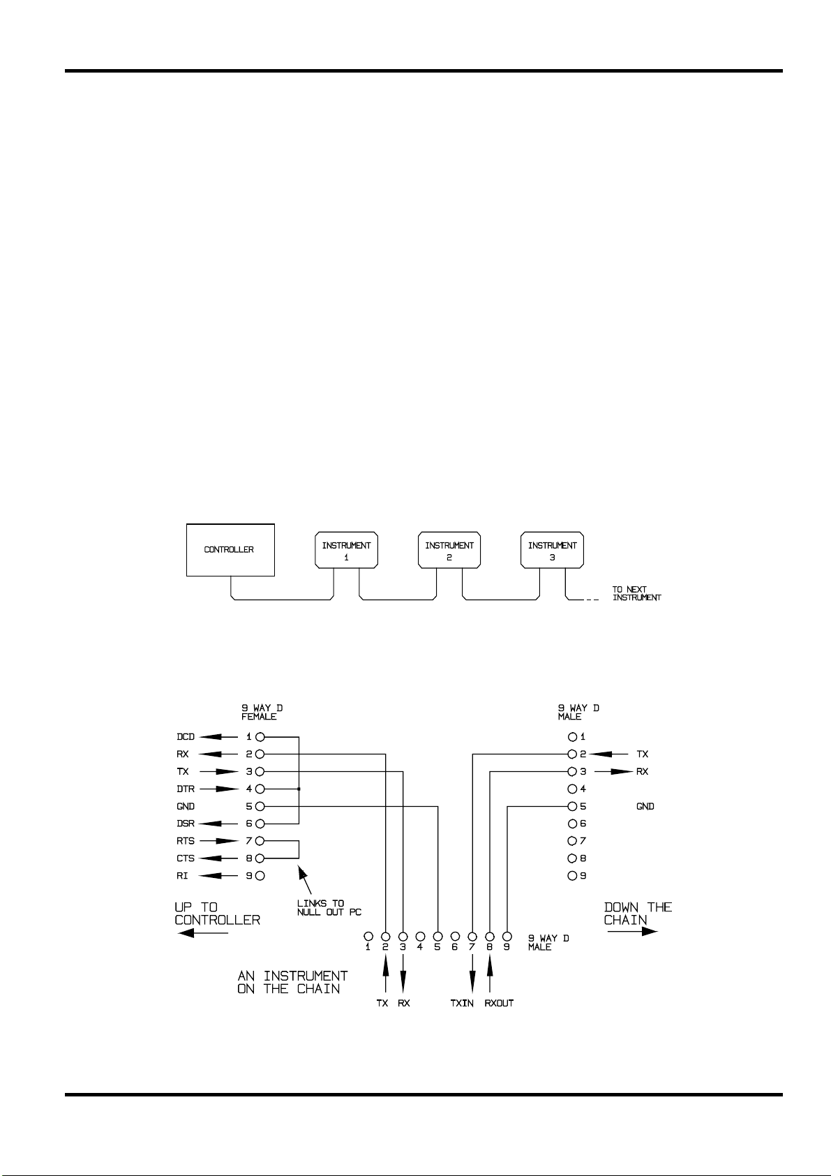
ARC Interface
Using a simple cable assembly, a `daisy chain' connection system between any number of
instruments, up to the maximum of 32 can be made, as shown below:
The daisy chain consists of the transmit data (TXD), receive date (RXD) and signal ground lines
only. There are no control/handshake lines. This makes XON/XOFF protocol essential and allows
the inter-connection between instruments to contain just 3 wires. The wiring of the adaptor cable
is shown below:
All instruments on the interface must be set to the same baud rate and all must be powered on,
otherwise instruments further down the daisy chain will not receive any data or commands.
13
Page 15

The ARC standard for the other interface parameters is as follows; in these power supplies (and
most other ARC instruments) they are fixed.
Start bits 1
Data bits 8
Parity None
Stop bits 1
ARC Character Set
Because of the need for XON/XOFF handshake it is possible to send ASCII coded data only;
binary blocks are not allowed. Bit 7 of ASCII codes is ignored, i.e. assumed to be low. No
distinction is made between upper and lower case characters in command mnemonics and they
may be freely mixed. The ASCII codes below 20H (space) are reserved for interface control.
ARC Interface Control Codes
All instruments intended for use on the ARC bus use the following set of interface control codes.
Codes between 00H and 1FH which are not listed here as having a particular meaning are
reserved for future use and will be ignored. Mixing interface control codes inside instrument
commands is not allowed except as stated below for CR and LF codes and XON and XOFF
codes.
When an instrument is first powered on it will automatically enter the Non- Addressable mode. In
this mode the instrument is not addressable and will not respond to any address commands. This
allows the instrument to function as a normal RS232 controllable device. This mode may be
locked by sending the Lock Non-Addressable mode control code 04H (LNA). The controller and
instrument can now freely use all 8 bit codes and binary blocks but all interface control codes are
ignored. To return to addressable mode the instrument must be powered off.
To enable addressable mode after a instrument has been powered on the Set Addressable Mode
control code, 02H (SAM), must be sent. This will then enable all instruments connected to the
ARC bus to respond to all interface control codes. To return to Non-Addressable mode the Lock
Non-Addressable mode control code must be sent which will disable addressable mode until the
instruments are powered off.
Before an instrument is sent a command it must be addressed to listen by sending the Listen
Address control code, 12H (LAD), followed by a single character which has the lower 5 bits
corresponding to the unique address of the required instrument, e.g. the codes A-Z or a-z give
the addresses 1-26 inclusive while @ is address 0 and so on. Once addressed to listen the
instrument will read and act upon any commands sent until the listen mode is cancelled.
Because of the asynchronous nature of the interface it is necessary for the controller to be
informed that an instrument has accepted the listen address sequence and is ready to receive
commands. The controller will therefore wait for code 06H (ACK) before sending any commands,
The addressed instrument will provide this ACK. The controller should time-out and try again if no
ACK is received within 5 seconds.
Listen mode will be cancelled by any of the following interface control codes being received:
12H LAD Listen Address followed by an address not
belonging to this instrument.
14H TAD Talk Address for any instrument.
03H UNA Universal Unaddress control code.
14
04H LNA Lock Non-Addressable mode control code.
18H UDC Universal Device Clear.
Page 16

Before a response can be read from an instrument it must be addressed to talk by sending the
Talk Address control code, 14H (TAD) followed by a single character which has the lower 5 bits
corresponding to the unique address of the required instrument, as for the listen address control
code above. Once addressed to talk the instrument will send the response message it has
available, if any, and then exit the talk addressed state. Only one response message will be sent
each time the instrument is addressed to talk.
Talk mode will be cancelled by any of the following interface control codes being received:
12H LAD Listen Address for any instrument.
14H TAD Talk Address followed by an address not
belonging to this instrument.
03H UNA Universal Unaddress control code.
04H LNA Lock Non-Addressable mode control code.
18H UDC Universal Device Clear.
Talk mode will also be cancelled when the instrument has completed sending a response
message or has nothing to say.
The interface code 0AH (LF) is the Universal Command and response Terminator (UCT); it must
be the last code sent in all commands and will be the last code sent in all responses.
The interface code 0DH (CR) may be used as required to aid the formatting of commands; it will
be ignored by all instruments. Most instruments will terminate responses with CR followed by LF.
The interface code 13H (XOFF) may be sent at any time by a listener (instrument or controller) to
suspend the output of a talker. The listener must send 11H (XON) before the talker will resume
sending. This is the only form of handshake control supported by ARC.
ARC Interface Control Code List
02H SAM Set Addressable mode.
03H UNA Universal Unaddress control code.
04H LNA Lock Non-Addressable mode control code.
06H ACK Acknowledge that listen address received.
0AH UCT Universal Command and response Terminator.
0DH CR Formatting code, otherwise ignored.
11H XON Restart transmission.
12H LAD Listen Address - must be followed by an address belonging to
the required instrument.
13H XOFF Stop transmission.
14H TAD Talk Address - must be followed by an address belonging to the
required instrument.
18H UDC Universal Device Clear.
GPIB Interface
The 24-way GPIB connector is located on the instrument rear panel.
The pin connections are as specified in IEEE Std. 488.1-1987 and the instruments in the range
comply with IEEE Std. 488.1-1987 and IEEE Std. 488.2-1987 and contain the following IEEE
488.1 subsets.
15
Page 17

GPIB Subsets
This instrument contains the following IEEE 488.1 subsets:
Source Handshake SH1
Acceptor Handshake AH1
Talker T6
Listener L4
Service Request SR1
Remote Local RL1
Parallel Poll PP1
Device Clear DC1
Device Trigger
Controller C0
Electrical Interface E2
* Although no Device Trigger capability is included, the GET message will not cause a
command error unless its position in the input stream dictates that it should; e.g. buried
inside a <PROGRAM MESSAGE UNIT>.
GPIB IEEE Std. 488.2 Error Handling
The IEEE 488.2 UNTERMINATED error (addressed to talk with nothing to say) is handled as follows.
If the instrument is addressed to talk and the response formatter is inactive and the input queue
is empty then the
in the Standard Event Status Register, a value of 3 to be placed in the Query Error Register and
the parser to be reset. See the STATUS REPORTING CAPABILITIES section for further
information.
UNTERMINATED error is generated. This will cause the Query Error bit to be set
DT0*
The IEEE 488.2
send a response message and a
or the input queue contains more than one END message then the instrument has been
INTERRUPTED and an error is generated. This will cause the Query Error bit to be set in the
Standard Event Status Register, a value of 1 to be placed in the Query Error Register and the
response formatter to be reset thus clearing the output queue. The parser will then start parsing
the next
<PROGRAM MESSAGE UNIT> from the input queue. See the STATUS REPORTING
CAPABILITIES section for further information.
The IEEE 488.2 DEADLOCK error is handled as follows. If the response formatter is waiting to send
a response message and the input queue becomes full then the instrument enters the
state and an error is generated. This will cause the Query Error bit to be set in the Standard Event
Status Register, a value of 2 to be placed in the Query Error Register and the response formatter
to be reset thus clearing the output queue. The parser will then start parsing the next
MESSAGE UNIT>
further information.
GPIB Parallel Poll
The power supplies offer complete parallel poll capabilities. The Parallel Poll Enable Register is
set to specify which bits in the Status Byte Register are to be used to form the
The Parallel Poll Enable Register is set by the ∗PRE <nrf> command and read by the ∗PRE?
command. The value in the Parallel Poll Enable Register is ANDed with the Status Byte Register;
if the result is zero then the value of
INTERRUPTED error is handled as follows. If the response formatter is waiting to
<PROGRAM MESSAGE TERMINATOR> has been read by the parser
DEADLOCK
<PROGRAM
from the input queue. See the STATUS REPORTING CAPABILITIES section for
ist local message
ist is 0 otherwise the value of ist is 1.
16
The instrument must also be configured so that the value of
ist can be returned to the controller
during a parallel poll operation. The instrument is configured by the controller sending a Parallel
Poll Configure command (PPC) followed by a Parallel Poll Enable command (PPE). The bits in
the PPE command are shown below:
Page 18

bit 7 = X don't care
bit 6 = 1
bit 5 = 1 Parallel poll enable
bit 4 = 0
bit 3 = Sense - sense of the response bit; 0 = low, 1 = high
bit 2 = ?
bit 1 = ? bit position of the response
bit 0 = ?
Example. To return the RQS bit (bit 6 of the Status Byte Register) as a 1 when true and a 0 when
false in bit position 1 in response to a parallel poll operation send the following commands
The parallel poll response from the generator will then be 00H if RQS is 0 and 01H if RQS is 1.
During parallel poll response the DIO interface lines are resistively terminated (passive
termination). This allows multiple devices to share the same response bit position in either wiredAND or wired-OR configuration, see IEEE 488.1 for more information.
Power on Settings
Most instrument settings are stored in non-volatile ram and will remain unchanged while power is
off. The following instrument status values are set at power on:
Status Byte Register = 0
Service Request Enable Register = 0
*
Standard Event Status Register = 128 (pon bit set)
Standard Event Status Enable Register = 0
*
Limit Event Status Register = 0 (Then set to show new limit status)
Limit Event Status Enable Register = 0
*
Execution Error Register = 0
Query Error Register = 0
Parallel Poll Enable Register = 0
*
∗PRE 64
<pmt>, then PPC followed by 69H (PPE)
* Registers marked thus are specific to the GPIB section of the instrument and are of limited
use in an ARC environment.
The standby state will be set and the instrument will be in local with the keyboard active. A
complete self-test will be performed just after power up and this will determine the values in the
Failed Output Register and the state of the FLT bit in the Status Byte Register.
Due to the non-volatile storage the power on settings are essentially modified by any command,
local or remote, which changes any value not listed above. If a defined state is require at start up
by the controller the *RST command should be issued which will load the settings as listed in the
description of that command.
If for any reason an error is detected at power up in the non-volatile ram a warning will be issued
and all settings will be returned to their default states as for a *RST command.
Status Reporting
This section describes the complete status model of the instrument. Note that some registers are
specific to the GPIB section of the instrument and are of limited use in an ARC environment.
17
Page 19

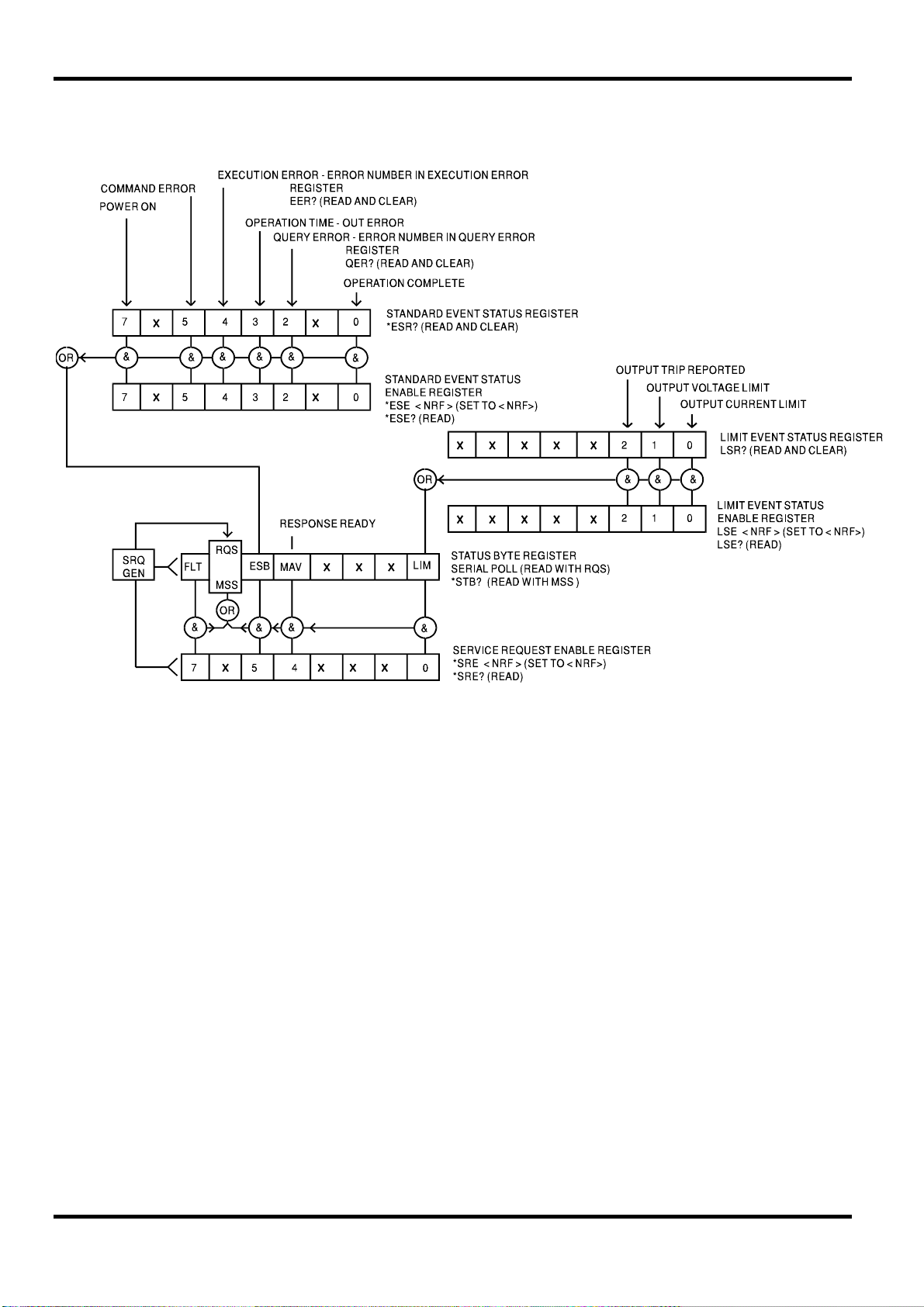
Standard Event Status and Standard Event Status Enable Registers
These two registers are implemented as required by the IEEE std. 488.2.
Any bits set in the Standard Event Status Register which correspond to bits set in the Standard
Event Status Enable Register will cause the ESB bit to be set in the Status Byte Register.
The Standard Event Status Register is read and cleared by the ∗ESR? command. The Standard
Event Status Enable register is set by the ∗ESE <nrf> command and read by the ∗ESE?
command.
Bit 7 - Power On. Set when power is first applied to the instrument.
Bit 6 - Not used.
Bit 5 - Command Error. Set when a syntax type error is detected in a command from the
bus. The parser is reset and parsing continues at the next byte in the input stream.
Bit 4 - Execution Error. Set when an error is encountered while attempting to execute a
completely parsed command. The appropriate error number will be reported in the
Execution Error Register, as listed below:
001 Checksum error in non-volatile ram at power on.
002 Output stage failed to respond - possibly a system fault.
003 Output stage trip has occurred - attempting to recover.
100 Maximum set voltage value exceeded.
101 Maximum set amps value exceeded.
102 Minimum set voltage exceeded.
103 Minimum set amps value exceeded.
104 Maximum delta voltage value exceeded.
105 Maximum delta amps value exceeded.
107 Minimum set OVP value exceeded.
108 Maximum set OVP value exceeded.
109 Minimum delta amps value exceeded.
110 Minimum delta voltage value exceeded.
114 Illegal bus address requested.
115 Illegal store number.
116 Recall empty store requested.
117 Stored data is corrupt.
118 Output stage has tripped (OVP or Temperature).
119 Value out of range.
18
Bit 3 - Operation Time-out Error. Set when an attempt is made to set an output to a specific
voltage value, with verify specified, and the output Volts do not settle within 5
seconds. this can happen if, for example, a large value of capacitance exists across
the output and the current limit is set to a very low value.
Bit 2 - Query Error. Set when a query error occurs. The appropriate error number will be
reported in the Query Error Register as listed below.
1 Interrupted error
2 Deadlock error
3 Unterminated error
Bit 1 - Not used.
Bit 0 -
Operation Complete. Set in response to the ∗OPC command.
Page 20

Limit Event Status Register and Limit Event Status Enable Register
These two registers are implemented as an addition to the IEEE std.488.2. Their purpose is to
allow the controller to be informed of entry to and/or exist from current limit by any output.
Any bits set in the Limit Event Status Register which correspond to bits set in the Limit Event
Status Enable Register will cause the LIM bit to be set in the Status Byte Register.
The Limit Event Status Register is read and cleared by the LSR? command. The Limit Event
Status Enable register is set by the LSE<nrf> command and read by the LSE? command.
Bit 7 ... Bit 3 are not used.
Bit 2 - Set when an output trip has occurred.
Bit 1 - Set when output enters voltage limit.
Bit 0 - Set when output enters current limit.
Status Byte Register and Service Request Enable Register
These two registers are implemented as required by the IEEE std. 488.2.
Any bits set in the Status Byte Register which correspond to bits set in the Service Request
Enable Register will cause the RQS/MSS bit to be set in the Status Byte Register, thus generating
a Service Request on the bus.
The Status Byte Register is read either by the ∗STB? command, which will return MSS in bit 6, or
by a Serial Poll which will return RQS in bit 6. The Service Request Enable register is set by the
∗SRE <nrf> command and read by the ∗SRE? command.
Bit 7 - FLT. This is the fault bit which will be set when an output fault is detected,
i.e. an execution error 002 has occurred.
Bit 6 - RQS/MSS. This bit, as defined by IEEE Std. 488.2, contains both the Requesting
Service message and the Master Status Summary message. RQS is returned in
response to a Serial Poll and MSS is returned in response to the ∗STB? command.
Bit 5 - ESB. The Event Status Bit. This bit is set if any bits set in the Standard Event Status
Register correspond to bits set in the Standard Event Status Enable Register.
Bit 4 - MAV. The Message Available Bit. This will be set when the instrument has a
response message formatted and ready to send to the controller. The bit will be
cleared after the Response Message Terminator has been sent.
Bit 3 - Not used.
Bit 2 - Not used.
Bit 1 - Not used.
Bit 0 - LIM. The Limit status bit. This bit is set if any bits set in the Limit Event Status
Register correspond to bits set in the Limit Event Status Enable Register.
19
Page 21
Status Model
ARC Remote Command Formats
Serial input to the instrument is buffered in a 256 byte input queue which is filled, under interrupt,
in a manner transparent to all other instrument operations. The instrument will send XOFF when
approximately 200 characters are in the queue. XON will be sent when approximately 100 free
spaces become available in the queue after XOFF was sent. This queue contains raw (unparsed) data which is taken, by the parser, as required. Commands (and queries) are executed in
order and the parser will not start a new command until any previous command or query is
complete. There is no output queue which means that the response formatter will wait, indefinitely
if necessary, until the instrument is addressed to talk and the complete response message has
been sent, before the parser is allowed to start the next command in the input queue.
Commands are sent as
or more
<PROGRAM MESSAGE UNIT> elements separated by <PROGRAM MESSAGE UNIT SEPARATOR>
elements.
<PROGRAM MESSAGES> are separated by <PROGRAM MESSAGE TERMINATOR> elements which
consist of the new line character (0AH).
A
<PROGRAM MESSAGE UNIT SEPARATOR> is the semi-colon character “;” (3BH).
<PROGRAM MESSAGE UNIT> is any of the commands in the REMOTE COMMANDS section.
A
Responses from the instrument to the controller are sent as
<RESPONSE MESSAGE> consists of one <RESPONSE MESSAGE UNIT> followed by a <RESPONSE
MESSAGE TERMINATOR>
<PROGRAM MESSAGES> by the controller, each message consists of zero
.
<RESPONSE MESSAGES>. A
20
Page 22

A <RESPONSE MESSAGE TERMINATOR> is the carriage return character followed by the new line
character (0DH 0AH).
Each query produces a specific
<RESPONSE MESSAGE> which is listed along with the command in
the REMOTE COMMANDS section.
<WHITE SPACE> is ignored except in command identifiers. e.g. “*∗C LS” is not equivalent to
“∗CLS”.
<WHITE SPACE> is defined as character codes 00H to 20H inclusive with the exception of
the codes specified as ARC interface commands.
The high bit of all characters is ignored.
The commands are case insensitive.
GPIB Remote Command Formats
GPIB input to the instrument is buffered in a 256 byte input queue which is filled, under interrupt,
in a manner transparent to all other instrument operations. The queue contains raw (un-parsed)
data which is taken, by the parser, as required. Commands (and queries) are executed in order
and the parser will not start a new command until any previous command or query is complete.
There is no output queue which means that the response formatter will wait, indefinitely if
necessary, until the instrument is addressed to talk and the complete response message has
been sent, before the parser is allowed to start the next command in the input queue.
Commands are sent as
or more
<PROGRAM MESSAGE UNIT> elements separated by <PROGRAM MESSAGE UNIT SEPARATOR>
elements.
<PROGRAM MESSAGES> are separated by <PROGRAM MESSAGE TERMINATOR> elements which may
be any of the following:
<PROGRAM MESSAGES> by the controller, each message consists of zero
NL The new line character (0AH)
NL^END The new line character with the END message
^END The END message with the last character of the message
<PROGRAM MESSAGE UNIT SEPARATOR> is the semi-colon character “;” (3BH).
A
<PROGRAM MESSAGE UNIT> is any of the commands in the REMOTE COMMANDS section.
A
Responses from the instrument to the controller are sent as
<RESPONSE MESSAGE> consists of one <RESPONSE MESSAGE UNIT> followed by a <RESPONSE
MESSAGE TERMINATOR>.
<RESPONSE MESSAGE TERMINATOR> is the new line character with the END message NL^END.
A
<RESPONSE MESSAGES>. A
Each query produces a specific <RESPONSE MESSAGE> which is listed along with the command in
the REMOTE COMMANDS section.
<WHITE SPACE> is ignored except in command identifiers. e.g. “∗C LS” is not equivalent to
“∗CLS”.
<WHITE SPACE> is defined as character codes 00H to 20H inclusive with the exception of
the NL character (0AH).
The high bit of all characters is ignored.
The commands are case insensitive.
21
Page 23

The following sections list all commands and queries implemented in these power supplies.
Those marked (†) are not available under ARC control.
Note that there are no dependent parameters, coupled parameters, overlapping commands,
expression program data elements or compound command program headers and that each
command is completely executed before the next command is started.
The following command sections use the following nomenclature:
<pmt>
<rmt>
<nrf> A number in any format. e.g. 12, 12·00, 1·2 e1 and 120 e-1 are all accepted as the
<nr1> A number with no fractional part, i.e. an integer.
<nr2> A number in fixed point format, e.g. 11·52, 0·78 etc.
<PROGRAM MESSAGE TERMINATOR>
<RESPONSE MESSAGE TERMINATOR>
number 12. Any number, when received, is converted to the required precision
consistent with the use then rounded up to obtain the value of the command.
Common Commands
Remote Commands
The commands in this section are those specified by IEEE Std. 488.2 as Common commands. All
will function when used on the ARC interface but some are of little use.
∗CLS
Sequential command.
Operation complete message generated immediately after execution.
Clear status. Clears the Standard Event Status Register, Limit Event Status Register, Query Error
Register and Execution Error Register. This indirectly clears the Status Byte Register.
∗ESE <nrf>
Sequential command.
Operation complete message generated immediately after execution.
Set the Standard Event Status Enable Register to the value of <nrf>. If the value of <nrf>, after
rounding, is less than 0 or greater than 255 an execution error is generated and error number 119
(out of range) is placed in the Execution Error Register.
∗ESE?
Sequential command.
Operation complete message generated immediately after <rmt> is sent.
Returns the value in the Standard Event Status Enable Register in <nr1> numeric format. The
syntax of the response is
22
<nr1><rmt>
Example. If the Standard Event Status Enable Register contains 01000001b the response
to ∗ESE? will be 65<rmt>.
Page 24

∗ESR?
∗IDN?
Sequential command.
Operation complete message generated immediately after <rmt> is sent.
Returns the value in the Standard Event Status Register in <nr1> numeric format. The register is
then cleared. The syntax of the response is
<nr1><rmt>
Example. If the Standard Event Status Register contains 01000001b the response to
∗ESR? will be 65<rmt>.
Sequential command.
Operation complete message generated immediately after <rmt> is sent.
Returns the instrument identification. The exact response is determined by the instrument
configuration and is of the form
<NAME>,<model>P,0,<version><rmt>
where <NAME> is the manufacturer's name, <MODEL> defines the type of instrument and
<VERSION> is the revision level of the software installed.
∗IST?
∗LRN?
Sequential command.
Operation complete message generated immediately after <rmt> is sent.
Returns ist local message as defined by IEEE Std. 488.2. The syntax of the response is
0<rmt>
if the local ist message is false or
1<rmt>
if the local ist message is true.
Sequential command.
Operation complete message generated immediately after <rmt> is sent.
Returns the complete set up of the instrument as a character data block. The block contains a
series of commands, separated by semi-colons, which specify the complete instrument set up
and may thus be returned to the instrument to re-install the set up. The syntax of the response is
LRN #0<Indefinite Length Binary Block data><rmt>
The size of the character data block is instrument type dependent.
The settings in the instrument are not affected by execution of the ∗LRN? command.
∗OPC
Sequential command.
Operation complete message generated immediately after execution.
Sets the Operation Complete bit (bit 0) in the Standard Event Status Register. This will happen
immediately the command is executed because of the sequential nature of all operations.
23
Page 25

∗OPC?
Sequential command.
Operation complete message generated immediately after <rmt> is sent.
Query operation complete status. The syntax of the response is
The response will be available immediately the command is executed because of the sequential
nature of all operations.
∗PRE <nrf>
Sequential command.
Operation complete message generated immediately after execution.
Set the Parallel Poll Enable Register to the value <nrf>. If the value of <nrf>, after rounding, is
less than 0 or greater than 255 an execution error is generated and error number 119 (Value out
of range) is placed in the Execution Error Register.
∗PRE?
Sequential command.
Operation complete message generated immediately after <rmt> is sent.
1<rmt>
Returns the value in the Parallel Poll Enable Register in <nr1> numeric format. The syntax of the
response is
Example. If the Parallel Poll Enable Register contains 01000001b the response to ∗PRE?
will be 65<rmt>.
∗RST
Sequential command.
Operation complete message generated immediately after execution.
Resets the instrument as follows. The output is set to minimum voltage, minimum current,
maximum OVP, meter damping off and output OFF. No other action taken.
∗RCL <nrf>
Sequential command.
Operation complete message generated immediately after execution.
Recall settings from store number <nrf>. The settings in the store pointed to by <nrf> are recalled
and installed as the instrument settings. If the value of <nrf> are recalled and installed as the
instrument settings. If the value of <nrf>, after rounding, is less than 1 or greater than 25 an
execution error is generated and error number 115 (illegal store number) is placed in the
Execution Error Register. If the requested store is empty execution error 116 (Recall empty store
requested) is generated. If the contents of the selected store are corrupt execution error 117
(Stored data is corrupt) is generated. Any of the above error conditions will result in no change of
the instrument settings.
<nr1><rmt>
24
The scope of the ∗RCL command is as follows:
The output is set to stored values of Volts, current, OVP, delta V and delta A.
The output status is set to the stored value.
Page 26

∗SRE <nrf>
Sequential command.
Operation complete message generated immediately after execution.
Set the Service Request Enable Register to <nrf>. If the value of <nrf>, after rounding, is less
than 0 or greater than 255 an execution error is generated and error number 119 (Value out of
range) is placed in the Execution Error Register.
∗SRE?
Sequential command.
Operation complete message generated immediately after <rmt> is sent.
Returns the value of the Service Request Enable Register in <nr1> numeric format. The syntax of
the response is
Example. If the Service Request Enable Register contains 01000001b the response to
∗SRE? will be 65<rmt>.
∗STB?
Sequential command.
Operation complete message generated immediately after <rmt> is sent.
<nr1><rmt>
Returns the value of the Status Byte Register in <nr1> numeric format. The syntax of the
response is
Example. If the Status Byte Register contains 01000001b the response to ∗STB? will be
65<rmt>.
∗SAV <nrf>
Sequential command.
Operation complete message generated immediately after execution.
Save settings to store number <nrf>. The instrument settings are saved in the store pointed to by
<nrf>. If the value of <nrf>, after rounding, is less than 1 or greater than 25 an execution error is
generated and error number 115 (illegal store number) is placed in the Execution Error Register.
The scope of the ∗SAV command is as follows:
The output is set to stored values of Volts, current, OVP, delta V and delta A.
The output status is set to the stored value.
∗TST?
Sequential command.
Operation complete message generated immediately after <rmt> is sent.
<nr1><rmt>
Examine the state of the FLT bit in the Status byte register and return the result. If the bit is clear
the response is
0<rmt>
any failure is indicated by a non-zero FLT bit and the response will be
1<rmt>
The value in the FLT bit is 1 if an execution error 002 has been reported since the instrument was
powered up.
25
Page 27

∗WAI
Sequential command.
Operation complete message generated immediately after execution.
Wait for operation complete true. As all commands are completely executed before the next is
started this command takes no additional action.
Instrument Specific Commands
The commands in this section are additional to those specified by IEEE Std. 488.2 as Common
Commands.
VV <nrf>
Sequential command
Operation complete message is generated once the new output voltage has settled to within ± 3
digits or 5% of the required value. If the voltage fails to settle within 5 seconds the Operation
Time-out Error (bit 3 in the Standard Event Status Register) will be set and the operation complete
message will then be generated.
Set the voltage to <nrf> and verify that the voltage is within ± 3 counts or 5% of the target value.
The value of <nrf> must be in Volts; no multipliers are allowed. If the value of <nrf>, after
rounding, is outside the range of the specified output an execution error will be generated and the
corresponding error number will be placed in the Execution Error Register, 100 (Maximum set
voltage value exceeded) if the value is too large and 102 (Minimum set voltage exceeded) if the
value is too small.
V <nrf>
Sequential command.
Operation complete message generated immediately after execution.
This command is identical to VV <nrf> above except that no verification of the output voltage is
performed, thus saving the possible 500ms required to read back the output voltage. This is
useful when it is known that the slew time will be short or during constant current operation.
I <nrf>
Sequential command.
Operation complete message generated immediately after execution.
Set current limit to <nrf>. The value of <nrf> must be in Amps; no multipliers are allowed. If the
value of <nrf>, after rounding, is outside the range of the specified output an execution error will
be generated and the corresponding error number will be placed in the Execution Error Register,
101 (Maximum set Amps value exceeded) if the value is too large or 103 (Minimum set Amps
value exceeded) if the value is too small.
OVP <nrf>
Sequential command.
Operation complete message generated immediately after execution.
Set OVP to <nrf>. The value of <nrf> must be in Volts; no multipliers are allowed. If the value of
<nrf>, after rounding, is outside the range of the specified output an execution error will be
generated and the corresponding error number will be placed in the Execution Error Register, 108
(maximum set OVP value exceeded) if the value is too large or 107 (Minimum set OVP value
exceeded) if the value is too small.
26
Page 28

V?
I?
OVP?
Sequential command.
Operation complete message generated immediately after <rmt> is sent.
Returns the set voltage in Volts in <nr2> numeric format.
The syntax of the response is
V<nr2><rmt>
Example: If the set voltage is 12.55 Volts the response to the command V? will be
V 12.55<rmt>.
Sequential command
Operation complete message generated immediately after <rmt> is sent.
Returns the current limit in Amps in <nr2> numeric format. The syntax of the response is
I <nr2><rmt>
Example: If the current limit is 1·000 Amps the response to the command I? will be
I 1.000<rmt>.
VO?
IO?
Sequential command.
Operation complete message generated immediately after <rmt> is sent.
Returns the OVP value in Volts in <nr2> numeric format. The syntax of the response is
OVP <nr2><rmt>
Example: If the OVP value is 33.00 Volts the response to the command OVP? will be
OVP 33.00<rmt>.
Sequential command
Operation complete message generated immediately after <rmt> is sent.
Reads and returns the output voltage in Volts in <nr2> numeric format. The syntax of the
response is
<nr2>V<rmt>
Example: If the output voltage is 12·55 Volts the response to the command VO? will be
12.55V<rmt>.
Sequential command
Operation complete message generated immediately after <rmt> is sent.
Reads and returns the output current in Amps in <nr2> numeric format. The syntax of the
response is
<nr2>A<rmt>
Example: If the output current is 0·934 Amps the response to the command
IO? will be 0.934A<rmt>.
27
Page 29

DELTAV <nrf>
Sequential command.
Operation complete message generated immediately after execution.
Set delta voltage to <nrf>. The value of <nrf> must be in Volts; no multipliers are allowed. If the
value of <nrf>, after rounding, is outside the range of the specified output an execution error will
be generated and the corresponding error number will be placed in the Execution Error Register,
104 (Maximum delta voltage value exceeded), if the value is too large or 109 (Minimum delta
voltage value exceeded) if the value is too small.
DELTAI <nrf>
Sequential command
Operation complete message generated immediately after execution.
Set delta Amps to <nrf>. The value of <nrf> must be in Amps; no multipliers are allowed. If the
value of <nrf>, after rounding, is outside the range of the specified output an execution error will
be generated and the corresponding error number will be placed in the Execution Error Register,
105 (Maximum delta Amps value exceeded), if the value is too large or 108 (Minimum delta amp
value exceeded) of the value is too small.
DELTAV?
Sequential command
Operation complete message generated immediately after <rmt> is sent.
Returns the delta voltage value in Volts in <nr2> numeric format. The syntax of the response is
Example: If the delta voltage is 0·55 Volts the response to the command
DELTAV? will be DELTAV 0.55<rmt>.
DELTAI?
Sequential command
Operation complete message generated immediately after <rmt> is sent.
Returns the delta current value in Amps in <nr2> numeric
format. The syntax of the response is
Example: If the delta current is 0·550 Amps the response to the command
DELTAI? will be DELTAI 0.550<rmt>.
INCVV
Sequential command
Operation complete message generated immediately after execution.
Increment the output voltage by the delta voltage value and verify that the voltage is within ±3
counts or 5% of the target value. If the value of the output voltage is outside the range for the
specified output the value is set to the maximum value allowed, no error is generated.
DELTAV <nr2><rmt>
DELTAI <nr2><rmt>
INCV
28
Sequential command
Operation complete message generated immediately after execution.
This command is identical to INCVV above except that no verification of the output voltage is
performed, thus saving the possible 500ms required to read back the output voltage. This is
useful when it is known that the slew time will be short or during constant current operation.
Page 30

DECVV
Sequential command
Operation complete message generated immediately after execution.
Decrement the output voltage by the delta voltage value and verify that the voltage is within ±3
counts or 5% of the target value. If the value of the output voltage is outside the range for the
specified output the value is set to the minimum value allowed, no error is generated.
DECV
Sequential command
Operation complete message generated immediately after execution.
This command is identical to DECVV above except that no verification of the output voltage is
performed, thus saving the possible 500ms required to read back the output voltage. This is
useful when it is known that the slew time will be short or during constant current operation.
INCI
Sequential command
Operation complete message generated immediately after execution.
Increment the set current by the delta current value. If the value of the set current is outside the
range for the specified output the value is set to the maximum value allowed, no error is
generated.
DECI
Sequential command
Operation complete message generated immediately after execution.
Decrement the set current by the delta current value. If the value of the set current is outside the
range for the specified output the value is set to the minimum value allowed, no error is
generated.
POWER
Sequential command
Operation complete message generated immediately after <rmt> is sent.
Returns the power being output from the instrument, in watts, in <nr2> numeric format. The
syntax of the response is
Example: If the output power is 175.3 watts the response to the command POWER? will be
175.3W<rmt>.
OP <nrf>
Sequential command
Operation complete message generated immediately after execution.
Sets the output status ON or OFF. If the value of <nrf>, after rounding, is 0 the output status will
be set to OFF if 1 the output status will be ON. If the value of <nrf> is not 0 or 1 execution error
119 (Value out of range) will be generated.
<nr2>W<rmt>
DAMPING <nrf>
Sequential command
Operation complete message generated immediately after execution.
Sets the current meter damping to OFF or ON. If the value of <nrf>, after rounding, is 0 the meter
damping will be set to OFF, if 1 the meter damping will be set to ON. If the value of <nrf> is not 0
or 1 execution error 119 (Value out of range) will be generated.
29
Page 31

LSR?
Sequential command
Operation complete message generated immediately after <rmt> is sent.
Returns the value in the Limit Event Status Register in <nr1> numeric format. The register is then
cleared. The syntax of the response is
Example: If the Limit Event Status Register contains 01000001b the response to LSR? will
be 65<rmt>.
LSE <nrf>
Sequential command
Operation complete message generated immediately after execution.
Set the Limit Event Status Enable Register to the value of <nrf>. If the value of <nrf>, after
rounding, is less than 0 or greater than 255 an execution error is generated and error number 119
(Value out of range) is placed in the Execution Error Register.
LSE?
Sequential command
Operation complete message generated immediately after <rmt> is sent.
<nr1><rmt>
EER?
QER?
Returns the value in the Limit Event Status Enable Register in <nr1> numeric format. The syntax
of the response is
<nr1><rmt>
Example: If the Limit Event Status Enable Register contains 01000001b the response to
LSE? will be 65<rmt>.
Sequential command
Operation complete message generated immediately after <rmt> is sent.
Returns the value in the Execution Error Register in <nr1> numeric format. The register is then
cleared. The syntax of the response is
<nr1><rmt>
Sequential command
Operation complete message generated immediately after <rmt> is sent.
Returns the value in the Query Error Register in <nr1> numeric format. The register is then
cleared. The syntax of the response is
<nr1><rmt>
BUZZER <nrf>
Sequential command
Operation complete message generated immediately after execution.
Sets the buzzer status to ON or OFF. If the value of <nrf>, after rounding, is 0 the buzzer status
will be set to OFF, if 1 the buzzer status will be set to ON. If the value of <nrf> is not 0 or 1
execution error 119 (Value out of range) will be generated.
30
Page 32

BUZZ
Sequential command.
Operation complete message generated immediately after execution.
Sounds the buzzer and sets the buzzer status to ON.
LRN #0<Indefinite Length Binary Block data><pmt>
Sequential command. (†)
Operation complete message generated immediately after execution.
Install all instrument settings from a previous ∗LRN? query. The response from a ∗LRN?
command is formatted such that the complete message may be returned to the instrument at any
time to restore the settings in effect when the ∗LRN? command was issued.
The scope of the LRN command is as follows;
The output is set to the values of Volts, current, OVP, delta V and delta A in the data block.
The output status is set to the value in the data block.
STO?
Sequential command. (†)
Operation complete message generated immediately after <rmt> is sent.
Returns the contents of the stores in the instrument as an Indefinite Length Binary Block. The
block is prefixed with the STO command and may thus be returned to the instrument to re-install
the stored settings.
The syntax of the response is
STO #0<Indefinite Length Binary Block data><rmt>
The size of the data block is instrument type dependent. The settings in the instrument are not
affected by execution of the STO? command.
STO #0<Indefinite Length Binary Block data><rmt>
Sequential command (†)
Operation complete message generated immediately after execution.
Install all stored data from a previous STO? query. The response from a STO? command is
formatted such that the complete message may be returned to the instrument at any time to
restore the data in effect when the STO? command was issued. The instrument settings are not
affected by the STO command but the contents of the stores are completely updated.
Remote Command SummaryCommon Commands
∗CLS
∗ESE <nrf>
∗ESE?
∗ESR?
∗IDN?
Clear Status.
Set the Standard Event Status Enable Register to the value of <nrf>.
Returns the value in the Standard Event Status Enable Register.
Returns the value in the Standard Event Status Register.
Returns the instrument identification.
∗IST?
∗LRN?
∗OPC
∗OPC?
31
Returns ist local message.
Returns the complete set up of the instrument.
Sets the Operation Complete bit in the Standard Event Status Register.
Returns the Operation Complete status.
Page 33

∗PRE <nrf>
∗PRE?
∗RCL <nrf>
∗RST
∗SRE <nrf>
∗SRE?
∗STB?
SAV<nrf> Save settings to store number <nrf>.
∗TST?
∗WAI
Other commands
V <nrf> Set the output voltage to <nrf>.
VV <nrf> Set the output voltage to <nrf> and verify.
I <nrf> Set current limit to <nrf>.
OVP <nrf> Set OVP to <nrf>.
Set the Parallel Poll Enable Register to the value <nrf>.
Returns the value in the Parallel Poll Enable Register.
Recall Settings from store <nrf>.
Resets the instrument.
Set the Service Request Enable Register to <nrf>.
Returns the value of the Service Request Enable Register.
Returns the value of the Status Byte Register.
Examine the state of the FLT bit in the Status byte register and return the result.
Wait for operation complete true.
V? Returns the set voltage in Volts.
I? Returns the current limit in Amps.
OVP? Returns the OVP value in Volts.
VO? Reads and returns the voltage in Volts.
IO? Reads and returns the output current in Amps.
DECI Decrement the set current by the delta current value.
DECV Decrement the output voltage by the delta voltage value.
DECVV Decrement the output voltage by the delta voltage value and verify.
DELTAI <nrf> Set delta Amps to <nrf>.
DELTAV <nrf> Set delta voltage to <nrf>.
DELTAI? Returns the delta current value in Amps.
DELTAV? Returns the delta voltage value in Volts.
INCI Increment the set current by the delta current value.
INCV Increment the output voltage by the delta voltage value.
INCVV Increment the output voltage by the delta voltage value and verify.
POWER? Returns the power being output from the instrument, in Watts.
32
OP <nrf> Set the output status ON or OFF.
DAMPING <nrf> Sets the meter damping to OFF or ON.
LSR? Returns the value in the Limit Event Status Register.
LSE <nrf> Set the Limit Event Status Enable Register to the value of <nrf>.
LSE? Returns the value in the Limit Event Status Enable Register.
Page 34

EER? Returns the value in the Execution Error Register.
QER? Returns the value in the Query Error Register.
BUZZER <nrf> Sets the buzzer status to ON or OFF.
BUZZ Sounds the buzzer and sets the buzzer status to ON.
LRN #0< Indefinite Length Binary Block data><pmt>
Install all stored data from a previous STO? query.
STO? Returns the contents of the stores.
STO #0<Indefinite Length Binary Block data><pmt>
Install all stored data from a previous STO? query.
33
Page 35

Sécurité
Ce système alimentation est un instrument de classe de sécurité 1 conforme à la classification
IEC et il a été conçu pour satisfaire aux exigences de la norme EN61010-1 (Exigences de
sécurité pour les équipements électriques de mesure, de contrôle et d'utilisation en laboratoire). Il
s'agit d'un instrument de Catégorie II d'installation devant être exploité depuis une alimentation
monophasée standard.
Cet instrument a été soumis à des essais conformément à EN61010-1 et il a été fourni en tout état de
sécurité. Ce manuel d'instructions contient des informations et avertissements qui doivent être suivis
par l'utilisateur afin d'assurer un fonctionnement de toute sécurité et de conserver l'instrument dans un
état de bonne sécurité.
Cet instrument a été conçu pour être utilisé en interne dans un environnement de pollution
Degré 2, plage de températures 5°C à 40°C, 20% - 80% HR (sans condensation). Il peut être
soumis de temps à autre à des températures comprises entre +5°C et –10°C sans dégradation
de sa sécurité. Ne pas l'utiliser lorsqu'il y a de la condensation.
Toute utilisation de cet instrument de manière non spécifiée par ces instructions risque d'affecter
la protection de sécurité conférée. Ne pas utiliser l'instrument à l'extérieur des tensions
d'alimentation nominales ou de la gamme des conditions ambiantes spécifiées.
AVERTISSEMENT! CET INSTRUMENT DOIT ETRE RELIE A LA TERRE
Toute interruption du conducteur de terre secteur à l'intérieur ou à l'extérieur de l'instrument rendra
l'instrument dangereux. Il est absolument interdit d'effectuer une interruption à dessein. Ne pas utiliser
de cordon de prolongation sans conducteur de protection, car ceci annulerait sa capacité de
protection.
Lorsque l'instrument est relié au secteur, il est possible que les bornes soient sous tension et par
suite, l'ouverture des couvercles ou la dépose de pièces (à l'exception de celles auxquelles on peut
accéder manuellement) risque de mettre à découvert des pièces sous tension. Il faut débrancher ke
cordon secteur de l'appareil avant de l'ouvrir pour effectuer des réglages, remplacements, travaux
d'entretien ou de réparations. Les condensateurs qui se trouvent dans le bloc d'alimentation risquent
de rester chargés, même si le bloc d'alimentation a été déconnecté de toutes les sources de tension,
mais ils se déchargeront en toute sécurité environ 10 minutes après extinction de l'alimentation.
Eviter dans la mesure du possible d'effectuer des réglages, travaux de réparations ou d'entretien
lorsque l'instrument ouvert est branché au secteur, mais si c'est absolument nécessaire, seul un
technicien compétent au courant des risques encourus doit effectuer ce genre de travaux.
S'il est évident que l'instrument est défectueux, qu'il a été soumis à des dégâts mécaniques, à une
humidité excessive ou à une corrosion chimique, la protection de sécurité sera amoindrie et il faut
retirer l'appareil, afin qu'il ne soit pas utilisé, et le renvoyer en vue de vérifications et de réparations.
Remplacer les fusibles uniquement par des fusibles d'intensité nominale requise et de type spécifié. Il
est interdit d'utiliser des fusibles bricolés et de court-circuiter des porte-fusibles.
L’instrument utilise une pile bouton au lithium pour la mémoire non-volatile ; sa durée de vie est
environ 5 ans. Pour son remplacement, utilisé une pile du même type : 3V Li/ Mn0
type 2032.
2
Les piles usées doivent être jetées en accord avec les lois locales ; ne pas les couper, les brûler,
les exposer à des températures au delà de 60°C ou essayer de la recharger.
34
Eviter de mouiller l'instrument lors de son nettoyage.
Les symboles suivants se trouvent sur l'instrument, ainsi que dans ce manuel.
Borne de terre (masse)
l
alimentation secteur ON (allume)
alimentation secteur OFF (éteinte)
courant continu (c.c.)
courant alternatif (c.a.)
Page 36

Tension de service
Vérifier que la tension opérationnelle de l'instrument indiquée sur le panneau arrière est
appropriée pour l'alimentation locale. S'il s'avère nécessaire de modifier la tension opérationnelle,
procéder de la manière décrite ci-dessous:
1. S'assurer que l'instrument est débranché de l'alimentation c.a.
2. Retirer les 6 vis qui maintiennent la partie supérieure du boîtier et démonter celle-ci en la
soulevant.
3. Changer les liaisons zéro-Ohm appropriées de la PCB à côté du transformateur:
Relier LK5 uniquement en vue de fonctionnement 230 V
Relier LK1 et LK3 uniquement en vue de fonctionnement 115 V
Montage
4. Effectuer le remontage dans l'ordre inverse.
5. Afin de respecter les impératifs des normes de sécurité, il faut changer la tension de
fonctionnement marquée sur le panneau arrière pour indiquer clairement le nouveau
réglage de tension.
le Câble secteur
Lorsqu'un câble secteur à trois conducteurs et aux extrémités dénudées est utilisé, celles-ci
doivent être connectées comme suit:
MARRON - SECTEUR-TENSION
BLEU - SECTEUR-NEUTRE
VERT/JAUNE - TERRE Symbole de prise de terre de sécurité
Lors de la pose d'une pre avec fusible, un fusible de 5 ampères doit être mis dans la prise. Les
couleurs des fils du câble secteur de cet appareil ne correspondant pas forcément aux couleurs
utilisées pour identifier les bornes de la prise, suivre la procédure ci-dessous :
Le fil vert et jaune doit être connecté à la borne de la prise près de laquelle figure la lettre E ou le
symbole de prise de terre de sécurité ci-dessus ou qui est de couleur verte ou verte/jaune.
Le fil bleu doit être connecté à la prise de la borne près de laquelle figure la lettre N ou qui est de
couleur noire.
Le fil marron doit être connecté à la borne près de laquelle figure la lettre L ou qui est de couleur
rouge.
ATTENTION ! CET APPAREIL DOIT ETRE MIS A LA TERRE
Toute interruption dans le conducteur de protection à l'intérieur ou à l'extérieur de l'instrument ou
tout débranchement de la borne masse de protection est susceptible de rendre l'appareil
dangereux. Toute interruption intentionnelle est interdite.
35
Page 37

Panneau avant
On utilise l’interrupteur d’alimentation pour appliquer la tension de ligne à l’instrument. Lorsque
l’instrument est allumé, il reçoit l’alimentation et la procédure de démarrage est exécutée; il faut
prévoir environ 5 secondes à cet effet. Si tout s’effectue correctement, les réglages suite à la
dernière extinction de l’appareil sont installés et l’instrument est prêt à être utilisé.
Les bornes de sortie se trouvent à droite du panneau avant. La borne rouge est positive et la
borne noire négative. La connexion aux bornes de sortie s’effectue d’une des manières
suivantes: fiches de 4 mm, cosses ou extrémités de câble. Les fils de connexion à la charge
doivent être de jauge de fil appropriée et courts, afin de réduire au minimum la chute de tension.
Les bornes de sortie sont reproduites sur le panneau arrière, conjointement avec les bornes de
détection.
Le clavier se trouve à gauche des bornes de sortie. Il est constitué de 27 touches et d'une DEL
qui indiquent l’état de sortie de l’instrument. L’utilisation du clavier pour le pilotage de toutes les
fonctions de l’instrument fait l’objet de discussions dans les sections qui suivent.
L’affichage d’état constitué d’un affichage de 4 chiffres, 7 segments et de 10 DEL se trouve à
gauche du clavier. L’affichage d’état indique généralement la puissance de sortie (en Watt)
lorsque la sortie est activée ou en blanc lorsqu’elle ne l’est pas; d’autres informations apparaîtront
toutefois lorsque des sélections sont effectuées au clavier. Les DEL de signalisation appropriées
indiquent la représentation du contenu de l’affichage à tout moment.
Fonctionnement manuel
Les affichages principaux et les voyants à DEL qui indiquent les conditions de la sortie sont situés
au-dessus du clavier. Les affichages indiquent la tension et le courant réglés lorsque la sortie est
désactivée et la tension aux bornes de sortie, ainsi que le courant de sortie, lorsque la sortie est
activée.
Une commande rotative en permanence qui peut être utilisée pour effectuer des ajustements de
précision de tension ou de courant comme décrit ci-après se trouve à droite des voyants à DEL.
Principes généraux du fonctionnement manuel
Les sections qui suivent expliquent de manière détaillée l’utilisation du clavier pour le pilotage de
toutes les fonctions de l’instrument. En cas d’erreur pendant l’utilisation du clavier, l’affichage
d’état indique Ennn où nnn représente un chiffre décimal. Une liste complète des erreurs
possibles se trouve à la section COMPTE-RENDU D’ETAT.
Réglage de tension
La tension réglée est généralement indiquée sur l’affichage supérieur gauche marqué V.
Toutefois, il faut préciser qu’il y a une exception lorsque la sortie est activée et qu’elle se trouve
en mode Courant constant (CI). Dans ce cas, la tension de sortie véritable est inférieure à la
valeur réglée et elle sera indiquée à la place.
Appuyer sur la touche VOLTS pour régler la tension. L’affichage d’état indique alors la valeur de
la tension réglée et la DEL VOLTS s’allume. Il est maintenant possible d’entrer une nouvelle
valeur au clavier numérique. La valeur sera en Volts et on peut utiliser la touche POINT pour
entrer les chiffres décimaux. Après entrée de la valeur requise, appuyer sur la touche CONFIRM
et la tension réglée sera immédiatement mise à jour. Pour quitter la procédure sans effectuer de
modifications, appuyer sur la touche ESCAPE. En cas d’erreur lors de la saisie, appuyer sur la
touche VOLTS et recommencer. Les valeurs minimales et maximales acceptées dépendront du
modèle particulier, se référer à la section Spécifications pour plus de détails à cet effet.
36
Page 38

Réglage de courant
Lorsque la sortie est désactivée, le courant réglé est indiqué sur l’affichage supérieur droit
marqué A. Lorsque la sortie est activée et en mode tension constante (CV), le courant de sortie
est indiqué. En mode Courant constant (CI), le courant de sortie est égal au courant réglé et sa
valeur est indiquée.
Appuyer sur la touche AMPS pour régler le courant. L’affichage d’état indique alors la valeur du
courant réglé et la DEL AMPS s’allume. Il est maintenant possible d’entrer une nouvelle valeur au
clavier numérique. La valeur sera en Ampères et on peut utiliser la touche POINT pour entrer les
chiffres décimaux. Après entrée de la valeur requise, appuyer sur la touche CONFIRM et le
courant réglé sera immédiatement mis à jour. Pour quitter la procédure sans effectuer de
modifications, appuyer sur la touche ESCAPE. En cas d’erreur lors de la saisie, appuyer sur la
touche AMPS et recommencer.
Les valeurs minimales et maximales acceptées dépendront du modèle particulier, se référer à la
section Spécifications pour plus de détails à cet effet.
Réglage de protection de surtension
La valeur de protection de surtension (OVP) n’est pas indiquée sur l’affichage principal; cette
fonction est toutefois toujours active et si à un moment quelconque la valeur véritable de la
tension de sortie dépasse la valeur réglée, le circuit OVP désactive immédiatement la sortie; ce
qui évite d’endommager le circuit soumis aux essais. Le circuit OVP assurera une protection
contre les réglages effectués par l’utilisateur de GPIB ou RS232, contre les tensions externes
produites entre les bornes de sortie, et contre toute défaillance du circuit de l’instrument en
question. En cas de déclenchement du circuit OVP pour une raison quelconque, les affichages
principaux affichent
suite au déclenchement et si cette opération réussit, le fonctionnement habituel recommence.
triP et la sortie est désactivée. Le système essaye alors de se rétablir
Appuyer sur la touche OVP pour activer la protection de surtension. L’affichage d’état indique la
valeur OVP réglée et la DEL OVP s’allume. Il est alors possible d’entrer une nouvelle valeur au
clavier numérique. La valeur sera en Volts et on peut utiliser la touche POINT pour entrer les
chiffres décimaux. Après entrée de la valeur requise, appuyer sur la touche CONFIRM et la
protection de surtension réglée sera immédiatement mise à jour. Pour quitter la procédure sans
effectuer de modifications, appuyer sur la touche ESCAPE. En cas d’erreur lors de la saisie,
appuyer sur la touche OVP et recommencer.
Les valeurs minimales et maximales acceptées dépendront du modèle particulier, se référer à la
section Spécifications pour plus de détails à cet effet.
Tension Delta
Appuyer sur la touche DeltaV pour passer au mode Delta Volts. L’affichage d’état indique alors la
tension Delta réglée et la DEL DeltaV s’allume. Il est maintenant possible d’entrer une nouvelle
valeur au clavier numérique. La valeur sera en Volts et on peut utiliser la touche POINT pour
entrer les chiffres décimaux. Après entrée de la valeur requise, appuyer sur la touche CONFIRM
et la tension Delta réglée sera immédiatement mise à jour. Pour quitter la procédure sans
effectuer de modifications, appuyer sur la touche ESCAPE. En cas d’erreur lors de la saisie,
appuyer sur la touche DeltaV et recommencer.
Lorsqu’on se trouve en mode DeltaV, c.-à-d. lorsque la DEL est allumée, les touches UP et
DOWN sont actives et elles entraînent une augmentation ou une réduction de la tension réglée
de la valeur DeltaV réglée indiquée sur l’affichage d’état. La DEL VOLTS située à côté du bouton
est également allumée et elle indique que le bouton est opérationnel pour pouvoir ajuster la
tension. Tourner le bouton pour augmenter ou réduire la valeur de la tension réglée par paliers de
10 mV, quelle que soit la valeur DeltaV réglée.
La valeur maximale de DeltaV est de 1,00 V et la valeur minimale 0,00V.
37
Page 39

Courant Delta
Appuyer sur la touche DeltaI pour passer au mode Delta Amps. L’affichage d’état indique alors le
courant Delta réglé et la DEL DeltaI s’allume. Il est maintenant possible d’entrer une nouvelle
valeur au clavier numérique. La valeur sera en Ampères et on peut utiliser la touche POINT pour
entrer les chiffres décimaux. Après entrée de la valeur requise, appuyer sur la touche CONFIRM
et le courant Delta réglé sera immédiatement mis à jour. Pour quitter la procédure sans effectuer
de modifications, appuyer sur la touche ESCAPE. En cas d’erreur lors de la saisie, appuyer sur la
touche DeltaI et recommencer.
Lorsqu’on se trouve en mode DeltaI, c.-à-d. lorsque la DEL est allumée, les touches UP et
DOWN sont actives et elles entraînent une augmentation ou une réduction du courant réglé de la
valeur DeltaI réglée indiquée sur l’affichage d’état. La DEL AMPS située à côté du bouton est
également allumée et elle indique que le bouton est opérationnel pour pouvoir ajuster le courant.
Tourner le bouton pour augmenter ou réduire la valeur de courant réglée par paliers de 10 mA,
quelle que soit la valeur DeltaI réglée.
La valeur maximale de DeltaI est de 1,00 A et la valeur minimale 0,00A.
Amortissement de l’ampèremètre
Appuyer sur la touche DAMPING pour activer et désactiver l’amortissement de l’ampèremètre de
sortie. La DEL DAMP est allumée lorsque l’amortissement est activé.
Sortie Marche/arrêt
Appuyer sur la touche OUTPUT pour activer et désactiver la sortie. La DEL ON située à côté de
la touche indique l’état de la sortie.
Stockage des réglages
L’instrument contient 25 mémoires, chacune en mesure de contenir la configuration complète.
Les données stockées ne sont pas volatiles et elles restent donc en mémoire après extinction de
l’alimentation.
Appuyer sur la touche STORE pour sauvegarder la configuration de l’instrument. L’affichage
d’état indique le numéro de la dernière mémoire à laquelle on a accédé. On peut utiliser cette
mémoire ou entrer un numéro de nouvelle mémoire au pavé numérique. Lorsque la valeur
requise est affichée, appuyer sur la touche CONFIRM pour mettre les données dans cette
mémoire. Appuyer sur la touche ESCAPE pour quitter la procédure sans effectuer de
modifications.
Rappel des réglages
L’instrument contient 25 mémoires, chacune en mesure de contenir la configuration complète.
Les données stockées ne sont pas volatiles et elles restent donc en mémoire après extinction de
l’alimentation.
Appuyer sur la touche RECALL pour rappeler la configuration de l’instrument. L’affichage d’état
indique le numéro de la dernière mémoire à laquelle on a accédé. On peut utiliser cette mémoire
ou entrer un numéro de nouvelle mémoire au pavé numérique. Lorsque la valeur requise est
affichée, appuyer sur la touche CONFIRM pour rappeler les données de cette mémoire. Appuyer
sur la touche ESCAPE pour quitter la procédure sans effectuer de modifications.
Déclenchement thermique
En cas de surchauffage de l’instrument, un déclenchement thermique intervient et les affichages
principaux indiquent le message
Cet état subsiste jusqu’à ce que l’instrument refroidisse en dessous de la température de
déclenchement et il sera alors possible de réutiliser la sortie.
38
triP. La sortie est alors désactivée, c.-à-d. qu’elle est éteinte.
Page 40

Connexions à la charge
Bornes de sortie
Il est possible d’effectuer des connexions au panneau avant au moyen de fiches de 4 mm, de
cosses ou d’extrémités de câbles. Les fils de connexion à la charge doivent être de jauge de fil
appropriée et courts, afin de réduire au minimum la chute de tension. Torsader les câbles de
charge pour réduire l’inductance.
La sortie est entièrement flottante et il est possible de relier une des deux bornes à la terre ou de
la mettre à une tension de crête jusqu’à 300 V au-dessus de la terre véritable; des tensions de ce
genre sont toutefois dangereuses et il faut donc prendre les mesures d’usage habituelles à cet
effet.
La limite de courant peut être réglée pour restreindre le courant de sortie continu à des niveaux
aussi bas que 10 mA. Un condensateur est généralement néanmoins relié entre les bornes pour
maintenir la stabilité et une bonne réponse transitoire, ainsi que c’est le cas de toutes les
alimentations de précision sur établi. Ce condensateur se charge jusqu’à la tension de sortie et
un court-circuitage de la sortie produit une courte impulsion de courant au fur et à mesure de la
décharge du condensateur qui est indépendante du réglage de limite de courant.
Bornes de détection
Utiliser l’option de transmission à distance pour corriger les erreurs provenant de la résistance
des fils de connexion à des courants plus élevés (10 mOhm de la résistance de fils entraîneront
une chute de 0,2 V à 20 A). Enlever les deux liaisons de court-circuitage effectuées entre la sortie
arrière et les bornes de détection et relier les bornes de détection directement à la charge; on
peut effectuer les connexions d’alimentation depuis les bornes avant ou depuis les bornes
arrière. Il faut torsader les bornes de détection avec les câbles de sortie correspondants avant de
torsader les câbles de sortie ensemble, afin d’assurer un bon accouplement entre la sortie et la
détection. La chute de tension dans chaque câble de sortie ne doit pas dépasser 1 V.
Reconnecter les liaisons de court-circuitage entre les bornes de sortie et de détection arrière
lorsque la télédétection n’est pas utilisée. La connexion de détection est toutefois effectuée de
manière interne par une résistance basse tension, de sorte qu’il y aura uniquement une légère
erreur entre la tension réglée et la tension véritable, si on laisse les liaisons déconnectées.
Déclenchement de détection de câblage incorrect
Il se produira un déclenchement de la sortie, si les câbles de détection sont câblés à la sortie
incorrecte, ou en cas de tentative de consommation d’alimentation à partir des câbles de
détection; le message
d’effectuer un rétablissement suite au déclenchement et si cette opération réussit (par suite d’une
correction du câblage), le message
triP apparaît sur les deux affichages. Le système s’efforce alors
triP disparaît et l’exploitation habituelle peut reprendre.
Protection de sortie
Outre la protection OVP de protection de surtension directe, la sortie est également protégée
contre toute tension inverse par une diode; le courant continu inverse ne doit pas dépasser 3 A,
mais les tensions transitoires peuvent avoir une valeur nettement supérieure.
Ventilation
Ces appareils sont extrêmement efficaces, mais ils peuvent néanmoins générer une chaleur
importante à plein régime. Les appareils sont refroidis par convection uniquement, il est donc
important, pour garantir les performances et la sécurité, d'assurer que la ventilation ne soit jamais
gênée. Si les appareils sont installés dans un espace réduit, tel qu'un rack de 19 pouces, une
ventilation adéquate doit être assurée, par exemple, par l'utilisation de ventilateurs.
39
Page 41

Le Constructeur ou ses agents à l'étranger répareront tout bloc qui tombe en panne. Si le
propriétaire de l'appareil décide d'effectuer ses propres réparations, ceci doit uniquement être
effectué par un personnel spécialisé qui doit se référer au manuel de révisions que l'on peut se
procurer directement auprès du Constructeur ou de ses agents à l'étranger.
Fusible
Le fusible qui convient pour tous les modèles et toutes les plages de CA est :
S'assurer que seuls les fusibles avec le courant nominal et le type spécifiés sont utilisés. Il est
interdit d'utiliser des fusibles expédients, ou de court-circuiter les porte-fusibles.
Pour remplacer le fusible, débrancher tout d'abord l'instrument de la source CA. Retirer les 6 vis
de fixation du couvercle et déposer le couvercle. Remplacer le fusible avec un fusible qui
convient et remettre en place le couvercle.
Il convient de noter que la fonction principale d'un fusible est de rendre l'appareil sûr, et de limiter
les dégâts en cas de panne d'un des dispositifs de commutation.
Si un fusible saute il est donc très probable que le fusible de remplacement sautera aussi, en
raison d'une défectuosité dans l'alimentation; dans ce cas l'instrument devra être renvoyé au
fabricant pour réparation.
Entretien et Réparations
10 Ampère 250V HBC à action retardée, 5 x 20 mm
Nettoyage
S'il faut nettoyer le bloc d'alimentation, utiliser un chiffon légèrement imbibé d'eau ou d'un
détergent doux. Nettoyer le cadran d'affichage au moyen d'un chiffon sec et doux.
AVERTISSEMENT! EMPECHER TOUTE INTRODUCTION D'EAU DANS LE BOITIER AFIN
D'EVITER TOUT CHOC ELECTRIQUE ET DEGATS AU BLOC D'ALIMENTATION. NE JAMAIS
UTILISER DE DISSOLVANTS POUR NETTOYER LE BLOC, AFIN D'EVITER
D'ENDOMMAGER LE BOITIER OU LE CADRAN D'AFFICHAGE.
40
Page 42

Fonctionnement à distance
Les sections suivantes décrivent en détails le fonctionnement de l'instrument par GPIB et ARC. Il
n’y a aucune différence entre ces deux modes lorsque le fonctionnement est identique. Lorsqu'il y
a des différences, elles sont indiquées dans les sections appropriées ou, dans certains cas, dans
des sections séparées pour GPIB et ARC. Il suffit donc de lire les sections générales et les
sections spécifiques à l'interface utile.
Sélection d’interface
Toutes les alimentations de la gamme sont munies d’une interface ARC (Chaîne adressable
RS232) et d’une interface GPIB. Avant de pouvoir utiliser une interface, il faut la sélectionner et
lui attribuer une adresse et/ou une vitesse de transmission. Appuyer sur la touche I/F pour
sélectionner une interface. L’affichage d’état indiquera soit “232” en cas de sélection courante
de RS232 , soit “488” en cas de sélection de GPIB. Appuyer sur les touches UP ou DOWN pour
changer l’interface sélectionnée. Appuyer sur la touche CONFIRM lorsque l’interface requise est
affichée pour la rendre opérationnelle. Appuyer sur la touche ESCAPE pour quitter la procédure
sans effectuer de modifications.
Sélection d’adresse et de vitesse de transmission
Pour que l’exploitation de chaque instrument relié à l’interface ARC ou GPIB réussisse, il faut lui
attribuer une adresse unique et dans le cas de l’interface ARC, tous les instruments doivent avoir
la même vitesse de transmission.
Appuyer sur la touche BAUD/ADDR pour afficher la vitesse de transmission ou l’adresse en cas
de sélection de RS232 ou l’adresse uniquement en cas de sélection de GPIB; la DEL
BAUD/ADDR est également allumée.
Utiliser les touches UP et DOWN pour sélectionner une autre vitesse de transmission en passant
par toutes les valeurs disponibles. Lorsque la valeur requise est affichée, appuyer sur la touche
CONFIRM pour la rendre opérationnelle. Appuyer sur la touche ESCAPE pour quitter la
procédure sans effectuer de modifications. Les vitesses de transmission qui peuvent être
sélectionnées sont de 300, 600, 1200, 2400, 4800 et 9600.
Pour sélectionner une adresse alternative, entrer le numéro requis au pavé numérique. Lorsque
la valeur requise est affichée, appuyer sur la touche CONFIRM pour la rendre opérationnelle.
Appuyer sur la touche ESCAPE pour quitter la procédure sans effectuer de modifications. La
gamme des adresses acceptées est comprise entre 0 et 30.
Tout changement d’adresse devient opérationnel dès son entrée au clavier et l’appareil ne répond
alors plus à l’adresse précédente.
Toutes les tâches effectuées par les dispositifs sont exécutées par une seule adresse primaire,
aucune adresse secondaire n’est nécessaire. L’adresse par défaut, c.-à-d. après panne de
mémoire vive non volatile est 11. En cas de changement d’adresse, le nouveau réglage est mis
dans une mémoire vive non volatile, et elle reste inchangée même après extinction de
l’alimentation.
L’interface RS232 peut également être utilisée en mode non adressable simple sans modification
aucune.
Fonctionnement à distance/local
A l’allumage, l’instrument se trouve à l’état local avec la DEL REMOTE éteinte. A cet état, toutes
les opérations peuvent être effectuées au clavier. Lors de l’adresse de l’instrument (pour parler
ou pour écouter), l’état à distance est entré et la DEL REMOTE s’allume. Dans ces conditions, le
clavier est bloqué et seules les commandes à distance sont traitées.
41
Page 43

On peut refaire passer l’instrument à l’état local en appuyant sur la touche LOCAL; toutefois,
l’effet de cette action reste en vigueur uniquement jusqu’à ce que l’instrument soit réadressé ou
qu’il reçoive un autre caractère de l’interface, et l’état à distance est alors rentré une fois de plus.
Le contrôleur peut désactiver la touche LOCAL sous contrôle de l’interface GPIB par
transmission d’une commande Local Lockout (LLO); le clavier de l’instrument reste
inopérationnel jusqu’à ce que le contrôleur transmette une commande Go To Local (GTL) ou qu’il
fasse passer la ligne d’interface REN à un état faux.
Interface ARC
Connexions de l'interface ARC
Le connecteur d'interface série à 9 voies, type D, se trouve sur le panneau arrière de l'instrument.
Les connexions des broches sont indiquées ci-dessous.
Broches Nom Description
1 - Pas de connexion interne
2 TXD Données transmises de l'instrument
3 RXD Données reçues à l'instrument
4 - Pas de connexion interne
5 GND Signal terre
6 - Pas de connexion interne
7 RXD2 Données secondaires reçues (voir le schéma)
8 TXD2 Données secondaires transmises (voir le schéma)
9 GND Signal terre
Les broches 2, 3 et 5 peuvent être utilisées en tant qu'interface classique RS232 avec
établissement de liaison XON/XOFF. Les broches 7, 8 et 9 sont en outre utilisées lorsque
l'instrument est relié à l'interface ARC.
On peut effectuer un système de connexion en "chaîne en guirlande" entre différents instruments,
maximum 32, au moyen d'un seul câble de la manière indiquée ci-dessous:
CONTROLEUR
INSTRUMENT
1
INSTRUMENT
2
INSTRUMENT
3
A L'INSTRUMENT
SUIVANT
La chaîne en guirlande est constituée des lignes de données de transmission (TXD), de
réception (RXD) et des lignes de terre de signaux uniquement. Il n'y a pas de lignes de
commande/établissement de liaison. Ceci rend essentiel le protocole XON/XOFF et permet à
l'interconnexion entre les instruments de contenir juste 3 fils. Le câblage du câble de l'adaptateur
est indiqué ci-dessous.
42
Page 44

Il faut régler tous les instruments de l'interface à la même vitesse de transmission et ils doivent
être allumés car sinon, les instruments de la chaîne à guirlande plus éloignés ne recevront pas
de données ni de commandes.
Les impératifs standard ARC des autres paramètres d'interface sont les suivants; dans le cas de
ces alimentations (et de la plupart des autres instruments ARC) ils sont fixes.
Bits de début 1
Bits de données 8
Parity Aucune
Bits d'arrêt 1
Jeu de caractères ARC
Par suite du besoin d'établissement de liaison avec XON/XOFF, il est possible de transmettre des
données codées ASCII uniquement; des blocs binaires ne sont pas admissibles. Il n'est pas tenu
compte du bit 7 des codes ASCII, car il est considéré comme étant bas. On ne fait pas de
différence entre les majuscules et les minuscules pour les mnémotechniques de commande et il
est facile de les mélanger. Les codes ASCII en dessous de 20H (espace) sont réservés pour la
commande d'interface.
Codes de contrôle de l'interface ARC
Tous les instruments qui doivent être utilisés sur le bus ARC utilisent le groupe de codes de
contrôle d'interface suivant. Les codes entre 00H et 1FH qui ne sont pas indiqués ici comme
ayant une signification particulière sont réservés en vue d'utilisation ultérieure et il n'en est pas
tenu compte. Des codes de contrôle de mélange d'interface à l'intérieur des commandes de
l'instrument ne sont pas admissibles sauf comme indiqué ci-dessous pour les codes CR et LF et
pour les codes XON et XOFF.
La première fois qu'on allume un instrument, il entre automatiquement en mode Non Adressable.
Dans ce mode, l'instrument n'est pas adressable et il ne répond pas aux commandes d'adresse.
Ceci permet à l'instrument de fonctionner en tant que dispositif RS232 habituel contrôlable. On
peut bloquer ce mode en transmettant le code de contrôle de mode Lock Non-Addressable 04H
(LNA). Le contrôleur et l'instrument peuvent maintenant utiliser librement tous les codes de 8 bits
et les blocs binaires, mais tous les codes de contrôle d'interface sont ignorés. Eteindre
l'instrument pour le faire retourner en mode adressable.
Il faut transmettre le code de contrôle Set Addressable Mode 02H (SAM) pour activer le mode
adressable après allumage de l'instrument. Ceci activera tous les instruments reliés au bus ARC
pour qu'ils répondent à tous les codes de contrôle d'interface. Transmettre le code de contrôle
Lock Non-Addressable mode qui désactive le mode adressable jusqu'à extinction de l'instrument
pour retourner en Non-Addressable mode.
43
Page 45

Avant qu'une commande soit transmise à un instrument, l'appareil doit être adressé sur écoute
par transmission du code de contrôle Listen Address, 12H (LAD), suivi d'un seul caractère dont
les 5 bits inférieurs correspondent à l'adresse unique de l'instrument requis, par exemple les
codes A-Z, ou a-z, donnent les adresses 1-26 incluses alors que @ est l'adresse zéro, etc. En
mode adressé sur écoute, l'instrument peut lire et réagir à toutes les commandes transmises
jusqu'à ce que le mode écoute soit annulé.
Par suite de la nature asynchrone de l'interface, le contrôleur doit être informé qu'un instrument a
accepté la séquence d'adresse d'écoute et qu'il est prêt à recevoir des commandes. Le
contrôleur attend donc le code 06H (ACK) avant de transmettre de commandes. L'instrument
adressé donne cette ACK. Le contrôleur doit retourner à zéro, puis recommencer l'opération, si
aucun code ACK n'est reçu dans les 5 secondes.
La réception d'un des codes de contrôle d'interface suivants annulera le mode écoute:
12H LAD Listen Address suivi d'une adresse non utilisée par cet instrument
14H TAD Talk Address pour tout instrument
03H NA Code de contrôle Universal Unaddress
04H LNA Code de contrôle de mode Lock Non-Addressable
18H UDC Universal Device Clear (Annulation dispositif universel)
Avant qu'une réponse puisse être lue par un instrument, il doit être adressé sur Parole par
transmission du code de contrôle Talk Address, 14H, (TAD) suivi d'un seul caractère dont les 5
bits inférieurs correspondent à l'adresse unique de l'instrument requis, de la même manière que
pour le code de contrôle d'adresse d'écoute ci-dessus. En mode adressé sur parole, l'instrument
transmet le message de réponse disponible, le cas échéant, puis sort de l'état adressé sur
parole.
La réception d'un des codes de contrôle d'interface suivants annulera le mode parole:
12H LAD Listen Address pour tout instrument
14H TAD Talk Address suivi d'une adresse non utilisée par cet instrument
03H UNA Code de contrôle Universal Unaddress
04H LNA Code de contrôle Lock Non-Addressable mode
18H UDC Universal Device Clear (Annulation dispositif universel)
Le mode parole sera également annulé lorsque l'instrument a fini d'envoyer un message de
réponse ou qu'il n'a rien à dire.
Le code d'interface 0AH (LF) est le Universal Command and response Terminator (UCT); ce code
doit être le dernier code transmis pour toutes les commandes et ce sera le dernier code transmis
dans toutes les réponses.
On peut utiliser le code d'interface ODH (CR) selon les besoins pour faciliter la mise en forme
des commandes; aucun instrument n'en tiendra compte. La plupart des instruments termineront
les réponses par CR suivi de LF.
L'appareil d'écoute (instrument ou contrôleur) peut transmettre à tout moment le code d'interface
13H (XOFF) pour arrêter la sortie d'un appareil de parole. L'appareil d'écoute doit transmettre le
code 11H (XON), avant que l'appareil phonique recommence la transmission. C'est la seule
forme de contrôle d'établissement de liaison gérée par ARC.
44
Page 46

Liste des codes de contrôle de l'interface ARC
02H SAM Set Addressable mode.
03H UNA Code de contrôle Universal Unaddress
04H LNA Code de contrôle Lock Non-Addressable mode
06H ACK Acknowledge adresse d'écoute reçue
0AH UCT Universal Command and response Terminator
0DH CR Code de mise en forme, sinon ignoré
11H XON Recommencement de la transmission
12H LAD Listen Address - doit être suivi d'une adresse utilisée par l'instrument requis
13H XOFF Arrêt de transmission
14H TAD Talk Address - doit être suivi d'une adresse utilisée par l'instrument requis
18H UDC Universal Device Clear (Annulation dispositif universel)
Interface GPIB
Lorsque l'interface GPIB est fixée, le connecteur à 24 voies GPIB est situé sur le panneau arrière
de l'instrument.
Les connexions des broches correspondent à celles qui sont spécifiées dans la norme IEEE Std.
488.1-1987 et l'instrument satisfait aux normes IEEE Std. 488.1-1987 et IEEE Std. 488.2-1987.
Sous-groupes GPIB
L'instrument contient les sous-groupes IEEE 488.1 suivants:
Source Handshake SH1
Acceptor Handshake AH1
Talker T6
Listener L4
Service Request SR1
Remote Local RL1
Parallel Poll PP1
Device Clear DC1
Device Trigger
Controller C0
Electrical Interface E2
* Bien qu’aucune capacité de déclenchement de dispositif ne soit incluse, le message GET
ne provoquera pas d’erreur de commande à moins que sa position dans le flot d’entrée
l’exige, par exemple s’il est dissimulé dans <PROGRAM MESSAGE UNIT>
DT0*
Gestion d'erreur GPIB IEEE Std 488.2
L'erreur UNTERMINATED IEEE 488.2 (adressée sur parole avec rien à dire) est gérée de la
manière suivante. Si l'instrument est adressé sur parole et que la mise en forme de réponse est
inactive et que la file d'attente d'entrée est vide, l'erreur
entraîne le réglage du bit Query Error dans le Standard Event Status Register et 3 est placé dans
le Query Error Register et l'analyseur syntaxique est réinitialisé. Voir la section CAPACITE DE
SIGNALISATION D'ETAT pour plus d'informations à cet effet.
45
UNTERMINATED se produit alors. Ceci
Page 47

L'erreur INTERRUPTED IEEE 488.2 est gérée de la manière suivante. Si la mise en forme de
réponse attend de transmettre un message de réponse et qu'un
TERMINATOR>
a été lu par l'analyseur syntaxique, ou que la file d'attente d'entrée contient plus
d'un message END, l'instrument est alors
le réglage du bit Query Error dans le Standard Event Status Register, 1 est placé dans le Query
Error Register et le formatage de réponse doit être réinitialisé pour dégager la file d'attente de
sortie. L'analyseur syntaxique commence alors l'analyse syntaxique du
suivant de la file d'attente d'entrée. Voir la section CAPACITE DE SIGNALISATION D'ETAT
UNIT>
pour plus d'informations à cet effet.
L'erreur
DEADLOCK IEEE 488.2 est gérée de la manière suivante. Si la mise en forme de
réponse attend de transmettre un message de réponse et que la file d'attente d'entrée est pleine,
l'instrument passe alors à l'état
bit Query Error dans le Standard Event Status Register, 2 est placé dans le Query Error Register
et la mise en forme de réponse est réinitialisée, ce qui dégage la file d'attente de sortie.
L'analyseur syntaxique commence à analyser la syntaxe du
TERMINATOR>
suivant de la file d'attente d'entrée. Voir la section CAPACITE DE
SIGNALISATION D'ETAT pour plus d'informations à cet effet.
Appel GPIB parallèle
Les alimentations offrent des capacités d'appel complètes en parallèle. Le Parallel Poll Enable
Register est réglé pour spécifier les bits du Status Byte Register utilisés pour constituer le
message local ist. Le Parallel Poll Enable Register est réglé par la commande ∗PRE<nrf> et lu
par la commande ∗PRE?. La valeur du Parallel Poll Enable Register est ANDed avec le Status
Byte Register; si le résultat est zéro, la valeur de
Il faut également configurer l'instrument de manière à pouvoir renvoyer la valeur de ist au
contrôleur pendant une opération d'appel en parallèle. La configuration de l'instrument s'effectue
par la transmission d'une commande Parallel Poll Configure (PPC) suivie d'une commande
Parallel Poll Enable (PPE) par le contrôleur. Les bits de la commande PPE sont indiqués cidessous:
<PROGRAM MESSAGE
INTERRUPTED et une erreur se produit. Ceci entraîne
<PROGRAM MESSAGE
DEADLOCK et une erreur se produit. Ceci entraîne le réglage du
<PROGRAM MESSAGE
ist est 0 et sinon, la valeur de ist est 1.
bit 7 = X ne joue aucun rôle
bit 6 = 1
bit 5 = 1 Parallel poll enable
bit 4 = 0
bit 3 = détection détection du bit de réponse; 0 = bas, 1 = haut
bit 2 = ?
bit 1 = ? position de bit de réponse
bit 0 = ?
Exemple: Pour renvoyer le bit RQS (bit 6 du Status Byte Register) en tant que 1, si vrai, et en tant que
0 si faux, dans la position de bit 1 en réponse à une opération d'appel en parallèle,
transmettre les commandes suivantes:
∗PRE64<pmt>, puis PPC suivi de 69H (PPE)
La réponse d'appel en parallèle de l'alimentation est alors 00h, si RQS est 0 et 01h si
RQS est 1.
Pendant la réponse d'appel en parallèle, les lignes d'interface DIO sont terminées de manière
résistive (terminaison passive). Ceci permet à des dispositifs multiples de partager la même
position de bit de réponse en configuration wired-AND ou wired-OR, voir IEEE 488.1 pour plus
d'informations à cet effet.
46
Page 48

Réglages à l’allumage
La plupart des réglages de l’instrument sont mis dans une mémoire non volatile et ils restent
inchangés tant que l’alimentation est éteinte. Les valeurs d’état suivantes de l’instrument sont
réglées à l’allumage.
Status Byte Register = 0
Service Request Enable Register = 0
∗
Standard Event Status Register =128 (pon bit réglé)
Standard Event Status Enable Register = 0
∗
Limit Event Status Register = 0 (Réglé pour indiquer l’état de nouvelle limite)
Limit Event Status Enable Register = 0
∗
Execution Error Register = 0
Query Error Register = 0
Parallel Poll Enable Register = 0
∗
∗ Les registres désignés avec un astérisque sont spécifiques à la section GPIB de
l’instrument et leur utilisation est limitée s’ils sont utilisés dans un environnement ARC.
L’état de réserve est réglé et l’instrument reste en mode local, le clavier opérationnel. Un essai
automatique complet est exécuté juste après l’allumage et ceci détermine les valeurs du Failed
Output Register ainsi que l’état du bit FLT du Status Byte Register:
Par suite de la nature non volatile de la mémoire, les réglages à l’allumage sont en fait modifiés
par toute commande, qu’elle soit locale ou à distance, en mesure de changer toute valeur
indiquée ci-dessus. Si le contrôleur a besoin d’un état défini au démarrage, il faut lancer la
commande *RST et elle chargera les réglages répertoriés dans la description de cette
commande.
En cas de détection d’une erreur au démarrage dans la mémoire vive non volatile pour quelle
raison que ce soit, un avertissement est émis et tous les réglages retournent à leur état par
défaut de la même manière que pour une commande *RST.
Signalisation d’état
Cette section décrit le modèle d'état complet de l'instrument. Il faut noter que certains registres
sont spécifiques à la section GPIB de l'instrument et qu'ils sont d'utilisation limitée dans un
environnement ARC.
La DEL ERROR est allumée lorsqu’il y a une erreur. Il sera nécessaire d’interroger les différents
registres d’état et d’erreur décrits ci-dessous pour rechercher la cause exacte de l’erreur.
Registres Standard Event Status et Standard Event Status Enable
Ces deux registres sont exploités selon les impératifs d'IEEE std. 488.2.
Tous les bits réglés dans le Standard Event Status Register qui correspondent aux bits réglés
dans le Standard Event Status Enable Register entraînent le réglage du bit ESB dans le Status
Byte Register.
Le Standard Event Status Register est lu et réinitialisé par la commande ∗ESR?. Le Standard
Event Status Enable Register est réglé par la commande ∗ESE <nrf> et lu par la commande
∗ESE?.
47
Page 49

Bit 7 - Allumage. Réglé la première fois que l'alimentation est appliquée à l'instrument..
Bit 6 - Non utilisé.
Bit 5 - Command Error. Réglé lorsqu'une erreur de type syntaxique est détectée dans une
commande du bus. L'analyseur syntaxique est réinitialisé et l'analyse continue à l'octet
suivant du flot d'entrée.
Bit 4 - Execution Error. Réglé lorsqu'il se produit une erreur pendant une tentative d'exécution
d'une commande où la syntaxe est entièrement analysée. Le numéro d'erreur approprié est
signalé dans le Execution Error Register, comme indiqué ci-dessous.
001 Erreur de total de contrôle dans une mémoire vive non volatile à l’allumage.
002 L’étage de sortie ne répond pas - éventuellement faute de système.
003 Déclenchement de l’étage de sortie - tentative de rétablissement.
100 Dépassement de la tension maximale réglée.
101 Dépassement du courant maximum réglé.
102 Dépassement de la tension minimale réglée.
103 Dépassement du courant minimum réglé.
104 Dépassement de la tension delta maximale réglée.
105 Dépassement du courant delta maximum réglé.
107 Dépassement de la protection de tension excessive minimale réglée.
108 Dépassement de la protection de tension excessive maximale réglée.
109 Dépassement du courant delta minimum réglé.
110 Dépassement de la tension delta minimale réglée.
114 Adresse de bus illégale demandée.
115 Numéro de mémoire illégal.
116 Rappel de mémoire vide demandée.
117 Données en mémoire altérées.
118 Déclenchement de l’étage de sortie (OVP ou température).
119 Valeur hors de gamme
Bit 3 - Operation Time-out Error. Réglé lors d’une tentative de régler une sortie à une tension
déterminée, avec spécification de vérification et que la tension de sortie ne se
stabilise pas dans les 5 secondes. Ceci peut se produire, si par exemple, il y a une
grande valeur capacitaire aux bornes de sortie et que la limite de courant est réglée à
une valeur très basse.
48
Bit 2 - Query Error. Réglé lorsqu'une erreur d'interrogation se produit. Le numéro d'erreur
approprié est signalé dans le Query Error Register, comme indiqué ci-dessous.
1 erreur interrompue
2 erreur point mort
3 erreur non terminée
Bit 1 - Non utilisé
Bit 0 - Operation Complete. Réglé en réponse à la commande *OPC.
Page 50

Limit Event Status Register et Limit Event Status Enable Register
Ces deux registres sont exploités en supplément des impératifs de IEEE std.488.2. Leur objet est
de signaler au contrôleur que toute sortie passe à la limite de courant et/ou en sort.
Tous les bits réglés dans le Limit Status Register qui correspondent aux bits réglés dans le Limit
Event Status Enable Register entraînent le réglage du bit LIM dans le Status Byte Register.
Le Limit Event Status Register est lu et annulé par la commande ∗LSR?. Le Limit Event Status
Enable Register est réglé par la commande LSE <nrf> et lu par la commande ∗LSE?.
Bit 7 -. Bit 3 non utilisés.
Bit 2 - Réglé lorsqu’un déclenchement de sortie s’est produit.
Bit 1 - Réglé lorsque la sortie entre dans la limite de tension.
Bit 0 - Réglé lorsque la sortie entre dans la limite de courant.
Status Byte Register et Service Request Enable Register
Ces deux registres sont exploités selon les impératifs d'IEEE Std. 488.2.
Tous les bits réglés dans le Status Byte Register qui correspondent aux bits réglés dans le
Service Request Enable Register entraînent le réglage du bit RQS/MSS dans le Status Byte
Register, ce qui produit un Service Request sur le bus.
Le Status Byte Register est lu soit par la commande ∗STB? qui renvoie MSS dans le bit 6, soit
par un Serial Poll qui renvoie RQS dans le bit 6. Le Service Request Enable Register est réglé
par la commande ∗SRE <nrf> et lu par la commande ∗SRE?.
Bit 7 - FLT. C’est le bit de faute qui est réglé lors de la détection d’une faute de sortie, c’est-
à-dire qu’une erreur d’exécution 002 s’est produite.
Bit 6 - RQS/MSS. Ce bit défini par IEEE Std. 488.2 contient le message Requesting Service
ainsi que le message Master Status Summary. RQS est renvoyé en réponse à une
commande Serial Poll et MSS en réponse à la commande ∗STB?.
Bit 5 - ESB. Event Status Bit. Ce bit est réglé si des bits réglés dans le Standard Event
Status Register correspondent aux bits réglés dans le Standard Event Status Enable
Register.
Bit 4 - MAV. Message Available Bit. Il est réglé lorsque l'instrument a un message de
réponse mis en forme et prêt à être transmis au contrôleur. Le bit est réinitialisé
après transmission du Response Message Terminator.
Bit 3 - Non utilisé.
Bit 2 - Non utilisé.
Bit 1 - Non utilisé.
Bit 0 - LIM. Limit Status Bit. Ce bit est réglé si des bits réglés dans le Limit Event Status
Register correspondent aux bits réglés dans le Limit Event Status Enable Register.
49
Page 51

Modèle Etat
Formats de commande à distance ARC
L'entrée série à l'instrument est séparée dans une file d'attente d'entrée de 256 octets qui est
remplie, sous interruption, d'une manière transparente pour toutes les autres opérations
d'instrument. L'instrument transmettra XOFF lorsque 200 caractères environ se trouvent dans la
file d'attente et XON lorsque 100 espaces libres environ sont disponibles dans la file d'attente
après la transmission de XOFF. Cette file d'attente contient des données pures (syntaxe non
analysée) prises par l'analyseur de syntaxe, selon les besoins. Les commandes (et
interrogations) sont exécutées dans l'ordre et l'analyseur de syntaxe ne commence pas de
nouvelle commande avant qu'une commande ou interrogation précédente soit effectuée. Il n'y a
pas de file d'attente de sortie, ce qui veut dire que la mise en forme de réponse attend,
indéfiniment le cas échéant, que l'instrument soit adressé sur parole et que le message de
réponse complet ait été transmis, avant que l'analyseur puisse commencer la commande
suivante à la file d'attente d'entrée.
Les commandes sont transmises en tant que
chaque message est constitué de zéro élément ou de plus d'éléments
séparés par les éléments <PROGRAM MESSAGE UNIT SEPARATOR>.
UNIT>
<PROGRAM MESSAGES> sont séparés par des éléments <PROGRAM MESSAGE
Les
TERMINATOR>
<PROGRAM MESSAGE UNIT SEPARATOR> est le point virgule ";" (3BH).
Un
constitués du caractère de nouvelle ligne (OAH).
<PROGRAM MESSAGES> par le contrôleur et
<PROGRAM MESSAGE
50
<PROGRAM MESSAGE UNIT> est l'une des commandes de la section COMMANDES A
Un
DISTANCE.
Les réponses de l'instrument au contrôleur sont transmises en tant que
MESSAGES>
d'un
<RESPONSE MESSAGE TERMINATOR>.
. Un <RESPONSE MESSAGE> est composé d'un <RESPONSE MESSAGE UNIT> suivi
<RESPONSE
Page 52

Un <RESPONSE MESSAGE TERMINATOR> est le caractère retour de chariot suivi du caractère de
nouvelle ligne (0DH 0AH).
Chaque interrogation produit un
<RESPONSE MESSAGE> spécifique listé avec la commande dans
la section COMMANDES A DISTANCE.
Il n'est pas tenu compte de
exemple "∗C LS" n'est pas équivalent à "∗CLS".
<WHITE SPACE> sauf dans les identificateurs de commande, par
<WHITE SPACE> est défini comme le code de
caractères 00H à 20H inclus à l'exception des codes spécifiés comme les commandes d'interface
ARC.
Il n'est pas tenu compte du bit niveau haut des différents caractères.
Les commandes acceptent des minuscules et des majuscules.
Formats de commande à distance GPIB
L'entrée GPIB à l'instrument est séparée dans une file d'attente d'entrée de 256 octets qui est
remplie, sous interruption, d'une manière transparente pour toutes les autres opérations
d'instrument. Cette file d'attente contient des données pures (syntaxe non analysée) prises par
l'analyseur de syntaxe, selon les besoins. Les commandes (et interrogations) sont exécutées
dans l'ordre et l'analyseur de syntaxe ne commence pas de nouvelle commande avant qu'une
commande ou interrogation précédente soit effectuée. Il n'y a pas de file d'attente de sortie, ce
qui veut dire que la mise en forme de réponse attend, indéfiniment le cas échéant, que
l'instrument soit adressé sur parole et que le message de réponse complet ait été transmis avant
que l'analyseur puisse commencer la commande suivante de la file d'attente d'entrée.
Les commandes sont transmises en tant que
chaque message est constitué de zéro élément ou de plus d'éléments
séparés par les éléments <PROGRAM MESSAGE UNIT SEPARATOR>.
UNIT>
<PROGRAM MESSAGES> par le contrôleur et
<PROGRAM MESSAGE
<PROGRAM MESSAGES> sont séparés par des éléments <PROGRAM MESSAGE
Les
TERMINATOR>
constitués d'un des caractères suivants:
NL Caractère de nouvelle ligne (OAH)
NL^END Caractère de nouvelle ligne avec le message END
^END Message END avec le dernier caractère du message.
Un
<PROGRAM MESSAGE UNIT SEPARATOR> est le point virgule ";" (3BH).
<PROGRAM MESSAGE UNIT> est l'une des commandes de la section COMMANDES A
Un
DISTANCE.
Les réponses de l'instrument au contrôleur sont transmises en tant que
MESSAGES>
d'un
<RESPONSE MESSAGE TERMINATOR>.
. Un <RESPONSE MESSAGE> est composé d'un <RESPONSE MESSAGE UNIT> suivi
<RESPONSE
Un <RESPONSE MESSAGE TERMINATOR> est le caractère de nouvelle ligne avec le message
END NL^END.
Chaque interrogation produit un
<RESPONSE MESSAGE> spécifique listé avec la commande dans
la section COMMANDES A DISTANCE.
Il n'est pas tenu compte de
exemple "∗C LS" n'est pas équivalent à "∗CLS".
<WHITE SPACE> sauf dans les identificateurs de commande, par
<WHITE SPACE> est défini comme le code de
caractères 00H à 20H inclus, à l'exception du caractère NL (0AH).
Il n'est pas tenu compte du bit niveau haut des différents caractères, sauf dans les blocs binaires.
Les commandes acceptent des minuscules et des majuscules.
51
Page 53

Commandes à distance
Les sections qui suivent énumèrent toutes les commandes et questions mises en oeuvre dans
ces alimentations. Celles qui sont marquées (†) ne sont pas disponibles sous contrôle ARC.
Il faut noter qu'il n'y a pas de paramètres dépendants, de paramètres couplés, de commandes de
chevauchement, d'éléments de données de programme d'expression, ni d'en-têtes de
programmes de commande composés, et que chaque commande est entièrement exécutée
avant le début de la commande suivante.
Les sections de commandes suivantes utilisent la nomenclature suivante:
<pmt>
<rmt>
<nrf> Nombre en tout format, par exemple 12, 12,00, 1,2e1 et 120e-1 sont tous acceptés
<nr1> Nombre sans partie fractionnaire, c.-à-d. nombre entier
<nr2> Nombre sous format à virgule fixe, par exemple 11,52, 0,78 etc.
<PROGRAM MESSAGE TERMINATOR>
<RESPONSE MESSAGE TERMINATOR>
en tant que nombre 12. Tout nombre reçu est converti à la précision requise
correspondant à l'utilisation, puis arrondi pour obtenir la valeur de la commande.
Commandes communes
Les commandes de cette section sont les commandes spécifiées par IEEE Std. 488.2 en tant que
commandes communes. Elles pourront toutes être utilisées sur l'interface ARC, mais certaines ne
seront pas spécialement utiles.
∗CLS
Commande de séquence.
Message opération terminée généré immédiatement après exécution.
Clear status. Dégage les registres Standard Event Status Register, Limit Event Status Register,
Query Error Register et Execution Error Register. Ceci réinitialise indirectement le registre Status
Byte Register.
∗ESE <nrf>
Commande de séquence.
Message opération terminée généré immédiatement après exécution.
Règle Standard Event Status Enable Register à la valeur de <nrf>. Si la valeur de <nrf>, après
arrondissement, est inférieure à 0 ou supérieure à 255, une erreur d'exécution se produit, et le
numéro d'erreur 200 (hors de la gamme) est mis dans le Execution Error Register.
∗ESE?
Commande de séquence.
Message opération terminée généré immédiatement après transmission de <rmt>.
Renvoie la valeur du Standard Event Status Enable Register sous format numérique <nr1>.
Syntaxe de la réponse:
Exemple: Si le Standard Event Status Enable Register contient 01000001b, la réponse à
∗ESE? sera de 65 <rmt>.
<nr1><rmt>
52
Page 54

∗ESR?
∗IDN?
Commande de séquence.
Message opération terminée généré immédiatement après transmission de <rmt>.
Renvoie la valeur du Standard Event Status Enable Register sous format numérique <nr1>. Le
registre est maintenant réinitialisé. Syntaxe de la réponse:
<nr1><rmt>
Exemple: Si le Standard Event Status Enable Register contient 01000001b, la réponse à
∗ESR? sera de 65 <rmt>.
Commande de séquence.
Message opération terminée généré immédiatement après transmission de <rmt>.
Renvoie l'identification de l'instrument. La réponse exacte est déterminée par la configuration de
l'instrument et elle a la forme suivante:
<NAME>,<model>P,0,<version><rmt>
où <NAME> est le nom du constructeur, <MODEL> définit le type d'instrument et <VERSION> le
niveau de révision du logiciel installé.
∗IST?
∗LRN?
Commande de séquence.
Message opération terminée généré immédiatement après transmission de <rmt>.
Renvoie le message local ist défini par la norme IEEE Std. 488.2. Syntaxe de la réponse:
0<rmt>
si le message local est faux ou
1<rmt>
si le message local est vrai.
Commande de séquence.
Message opération terminée généré immédiatement après transmission de <rmt>.
Renvoie la configuration complète de l’instrument sous forme de bloc de données de caractères.
Le bloc contient une série de commandes, séparées par des points virgules, qui spécifient la
configuration complète de l’instrument et qui peuvent donc retourner à l’instrument pour
réinstaller la configuration.
Syntaxe de la réponse:
LRN #0<Indefinite Length Binary Block data><rmt>
La taille du bloc de données de caractères dépend du type de l’instrument.
Les réglages de l'instrument ne sont pas affectés par l'exécution de la commande ∗LRN?.
∗OPC
Commande de séquence.
Message opération terminée généré immédiatement après exécution.
Règle le bit opération terminée (bit 0) dans le Standard Event Status Register. Ceci se produit
immédiatement après exécution de la commande par suite de la nature séquentielle de toutes les
opérations.
53
Page 55

∗OPC?
Commande de séquence.
Message opération terminée généré immédiatement après transmission de <rmt>.
Interrogation d'état opération terminée. Syntaxe de la réponse:
La réponse est disponible immédiatement après exécution de la commande par suite de la nature
séquentielle de toutes les opérations.
∗PRE <nrf>
Commande de séquence.
Message opération terminée généré immédiatement après exécution.
Régler le Parallel Poll Enable Register à la valeur <nrf>. Si la valeur de <nrf>, après
arrondissement est inférieure à 0 ou supérieure à 255, une erreur d'exécution se produit et le
numéro d'erreur 119 (valeur hors de gamme) est mis dans le Execution Error Register.
∗PRE?
Commande de séquence.
Message opération terminée généré immédiatement après transmission de <rmt>.
1<rmt>
Renvoie la valeur du Parallel Poll Enable Register sous format numérique <nr1>. Syntaxe de la
réponse:
Exemple: Si le Parallel Poll Enable Register contient 01000001b, la réponse à ∗PRE? sera
de 65 <rmt>.
∗RST
Commande de séquence.
Message opération terminée généré immédiatement après exécution.
Réinitialise l’instrument de la manière suivante. La sortie est réglée à la tension minimale, au
courant minimum, OVP maximale, amortissement de l’appareil à l’arrêt et sortie désactivée.
Aucune autre action n’est exécutée.
∗RCL <nrf>
Commande de séquence.
Message opération terminée généré immédiatement après exécution.
Rappel des réglages de la mémoire numéro <nrf>. Les réglages de la mémoire désignée par
<nrf> sont rappelés et installés en tant que réglages d’instrument. Si les valeurs de <nrf>
rappelées et installées en tant que réglages d’instrument après leur arrondissement sont
inférieures à 1 ou supérieures à 25, une erreur d’exécution est générée et le numéro d’erreur 115
(numéro de mémoire illégal) est mis dans le Execution Error Register. Si la mémoire demandée
est vide, l’erreur d’exécution 116 (Rappel de mémoire vide demandée) est générée. Si le contenu
de la mémoire sélectionnée est altéré, l’erreur d’exécution 117 (données stockées altérées) est
générée. Toutes les conditions d’erreur ci-dessus ne provoquent pas de changement de réglage
de l’instrument.
<nr1><rmt>
Le but de la commande *RCL est le suivant:
La sortie est réglée aux valeurs de tension, courant, OVP; delta V et delta A en mémoire.
L’état de sortie est réglé à la valeur en mémoire.
54
Page 56

∗SRE <nrf>
Commande de séquence.
Message opération terminée généré immédiatement après exécution.
Règle Service Request Enable Register à <nrf>. Si la valeur de <nrf>, après arrondissement, est
inférieure à 0 ou supérieure à 255, une erreur d'exécution se produit, et le numéro d'erreur 119
(hors de la gamme) est mis dans le Execution Error Register.
∗SRE?
Commande de séquence.
Message opération terminée généré immédiatement après transmission de <rmt>.
Renvoie la valeur de Service Request Enable Register sous format numérique <nr1>. Syntaxe de
la réponse:
Exemple: Si le Service Request Enable Register contient 01000001b, la réponse à ∗SRE?
sera de 65 <rmt>.
∗STB?
Commande de séquence.
Message opération terminée généré immédiatement après transmission de <rmt>.
<nr1><rmt>
Renvoie la valeur de Status Byte Register sous format numérique <nr1>. Syntaxe de la réponse:
<nr1><rmt>
Exemple: Si le Status Byte Register contient 01000001b, la réponse à ∗STB? sera de 65 <rmt>.
∗SAV <nrf>
Commande de séquence.
Message opération terminée généré immédiatement après exécution.
Sauvegarde des réglages dans la mémoire numéro <nrf>. Les réglages de l’instrument sont
sauvegardés dans la mémoire désignée par <nrf>. Si la valeur de <nrf>, après son
arrondissement, est inférieure à 1 ou supérieure à 25, une erreur d’exécution est générée et le
numéro d’erreur 115 (numéro de mémoire illégal) est mis dans le Execution Error Register.
Le but de la commande *SAV est le suivant:
La sortie est réglée aux valeurs de tension, courant, OVP; delta V et delta A en mémoire.
L’état de sortie est réglé à la valeur en mémoire.
*TST?
Commande de séquence.
Message opération terminée généré immédiatement après transmission de <rmt>.
Examine l’état du bit FLT dans le Status Byte Register et renvoie le résultat. Si le bit est remis à
zéro, a réponse est la suivante:
0<rmt>
tout défaut est indiqué par un bit FLT non zéro et la réponse est:
1<rmt>
La valeur du bit FLT est 1 si une erreur d’exécution 002 a été signalée depuis l’allumage de
l’instrument.
55
Page 57

∗WAI
Commande de séquence.
Message opération terminée généré immédiatement après exécution.
Attendre la fin de l'opération. Comme toutes les commandes sont entièrement exécutées avant
que la suivante commence, cette commande ne joue pas de rôle supplémentaire.
Commandes spécifiques de l'instrument
Les commandes de cette section s'ajoutent aux commandes spécifiées par la norme IEEE Std.
488.2 en tant que commandes communes.
VV <nrf>
Commande de séquence
Le message opération terminée est généré lorsque la nouvelle tension de sortie s’est stabilisée à
± 3 chiffres ou à 5% de la valeur requise. Si la tension ne parvient pas à se stabiliser dans les 5
secondes, l’erreur Operation Time-out (bit 3 du Standard Event Status Register) est activée et le
message opération complète est alors généré.
Régler la tension à <nrf> et vérifier que la tension est à ±3 comptes ou à 5% de la valeur cible. La
valeur <nrf> doit être en Volts; aucun multiplicateur n’est admissible. Si la valeur <nrf>, après
arrondissement, se trouve à l’extérieur de la gamme de la sortie spécifiée, une erreur d’exécution
sera générée et le numéro d’erreur correspondant sera mis dans le Execution Error Register, 100
(dépassement de la tension maximale réglée) si la valeur est trop grande et 120-102
(dépassement de la tension minimale réglée) si la valeur est trop basse.
V <nrf>
Commande séquence
Message opération terminée généré immédiatement après exécution.
Cette commande est identique à la commande VV <nrf> ci-dessus si ce n’est qu’aucune
vérification de la tension de sortie n’est exécutée, ce qui économise les 500 ms qui peuvent
s’avérer nécessaires pour relire la tension de sortie. Ceci s’avère utile lorsqu’on sait que le temps
de balayage sera court ou en cas d’exploitation en courant constant.
IV <nrf>
Commande de séquence
Message opération terminée généré immédiatement après exécution.
Régler la limite de courant à <nrf>. La valeur <nrf> doit être en Ampères; aucun multiplicateur
n’est admissible. Si la valeur <nrf>, après arrondissement, se trouve à l’extérieur de la gamme de
la sortie spécifiée, une erreur d’exécution sera générée et le numéro d’erreur correspondant sera
mis dans le Execution Error Register, 101 (dépassement du courant maximum réglé) si la valeur
est trop grande et 103 (dépassement du courant minimum réglé) si la valeur est trop basse.
OVP <nrf>
Commande de séquence
Message opération terminée généré immédiatement après exécution.
Régler OVP à <nrf>. La valeur <nrf> doit être en Volt; aucun multiplicateur n’est admissible. Si la
valeur <nrf>, après arrondissement, se trouve à l’extérieur de la gamme de la sortie spécifiée,
une erreur d’exécution sera générée et le numéro d’erreur correspondant sera mis dans le
Execution Error Register, 108 (dépassement de la protection de tension excessive minimale
réglée) si la valeur est trop grande ou 107 (dépassement de la protection de tension excessive
minimale) si la valeur est trop petite.
56
Page 58

V?
I?
OVP?
Commande de séquence
Message opération terminée généré immédiatement après transmission de <rmt>.
Renvoie la tension réglée en Volts sous format numérique <nr2>.
Syntaxe de la réponse
V<nr2><rmt>
Exemple: Si la tension réglée est 12,55 V, la réponse à la commande
V? sera V 12,55<rmt>.
Commande de séquence
Message opération terminée généré immédiatement après transmission de <rmt>.
Renvoie la limite de courant en Ampères sous format numérique <nr2>.
Syntaxe de la réponse
I<nr2><rmt>
Exemple: Si la limite de courant est 1,000 A, la réponse à la commande
I? sera I 1,000<rmt>.
VO?
IO?
Commande de séquence
Message opération terminée généré immédiatement après transmission de <rmt>.
Renvoie la valeur OVP en Volts sous format numérique <nr2>.
Syntaxe de la réponse
OVP<nr2><rmt>
Exemple: Si la valeur OVP est 33,00 V, la réponse à la commande
OVP? sera OVP 33,00<rmt>.
Commande de séquence
Message opération terminée généré immédiatement après transmission de <rmt>.
Lit et renvoie la tension de sortie en Volts sous format numérique <nr2>.
Syntaxe de la réponse
<nr2>V<rmt>
Exemple: Si la tension de sortie est 12,55 V, la réponse à la commande VO?
sera 12,55 V<rmt>.
Commande de séquence
Message opération terminée généré immédiatement après transmission de <rmt>.
Lit et renvoie le courant de sortie en Ampères sous format numérique <nr2>.
Syntaxe de la réponse
<nr2>A<rmt>
Exemple: Si le courant de sortie est 0,934 A, la réponse à la commande
IO? sera 0,934 A<rmt>.
57
Page 59

DELTAV<nrf>
Commande de séquence
Message opération terminée généré immédiatement après exécution.
Régler la tension delta à <nrf>. La valeur <nrf> doit être en Volts; aucun multiplicateur n’est
admissible. Si la valeur <nrf>, après arrondissement, se trouve à l’extérieur de la gamme de la
sortie spécifiée, une erreur d’exécution sera générée et le numéro d’erreur correspondant sera
mis dans le Execution Error Register, 104 (dépassement de la tension delta maximale), si la
valeur est trop grande ou 109 (dépassement de la tension delta minimale), si la valeur est trop
petite.
DELTAI<nrf>
Commande de séquence
Message opération terminée généré immédiatement après exécution.
Régler le courant delta à <nrf>. La valeur <nrf> doit être en Ampères; aucun multiplicateur n’est
admissible. Si la valeur <nrf>, après arrondissement, se trouve à l’extérieur de la gamme de la
sortie spécifiée, une erreur d’exécution sera générée et le numéro d’erreur correspondant sera
mis dans le Execution Error Register, 105 (dépassement du courant delta maximum), si la valeur
est trop grande ou 108 (dépassement du courant delta minimum), si la valeur est trop petite.
DELTAV?
Commande de séquence
Message opération terminée généré immédiatement après transmission de <rmt>.
Renvoie la tension delta en Volts sous format numérique <nr2>.
Syntaxe de la réponse
Exemple: Si la tension delta est 0,55 V, la réponse à la commande DELTAV?
sera DELTAV 0,55<rmt>.
DELTAI?
Commande de séquence
Message opération terminée généré immédiatement après transmission de <rmt>.
Renvoie le courant delta en Ampères sous format numérique <nr2>.
Syntaxe de la réponse
Exemple: Si le courant delta est 0,550 A, la réponse à la commande
DELTAI? sera DELTAI 0,550<rmt>.
INCVV
Commande de séquence
Message opération terminée généré immédiatement après exécution.
DELTAV<nr2><rmt>
DELTAI <nr2><rmt>
58
Augmenter la tension de sortie de la tension delta et vérifier que la tension est à ±3 comptes ou
à 5% de la valeur cible. Si la tension de sortie est hors de la gamme pour la sortie spécifiée, la
valeur est réglée à la valeur maximale admissible et aucune erreur n’est générée.
Page 60

INCV
Commande de séquence
Message opération terminée généré immédiatement après exécution.
Cette commande est identique à la commande INCVV ci-dessus si ce n’est qu’aucune vérification
de la tension de sortie n’est exécutée, ce qui économise les 500 ms qui peuvent s’avérer
nécessaires pour relire la tension de sortie. Ceci s’avère utile lorsqu’on sait que le temps de
balayage sera court ou en cas d’exploitation en courant constant.
DECVV
Commande de séquence
Message opération terminée généré immédiatement après exécution.
Réduire la tension de sortie de la tension delta et vérifier que la tension est à ±3 comptes ou à
5% de la valeur cible. Si la tension de sortie est hors de la gamme pour la sortie spécifiée, la
valeur est réglée à la valeur minimale admissible et aucune erreur n’est générée.
DECV
Commande de séquence
Message opération terminée généré immédiatement après exécution.
Cette commande est identique à la commande DECVV ci-dessus si ce n’est qu’aucune
vérification de la tension de sortie n’est exécutée, ce qui économise les 500 ms qui peuvent
s’avérer nécessaires pour relire la tension de sortie. Ceci s’avère utile lorsqu’on sait que le temps
de balayage sera court ou en cas d’exploitation en courant constant.
INCI
Commande de séquence
Message opération terminée généré immédiatement après exécution.
Augmenter le courant réglé du courant delta. Si le courant réglé est hors de la gamme pour la
sortie spécifiée, la valeur est réglée à la valeur maximale admissible et aucune erreur n’est
générée.
DECI
Commande de séquence
Message opération terminée généré immédiatement après exécution.
Réduire le courant réglé du courant delta. Si le courant réglé est hors de la gamme pour la sortie
spécifiée, la valeur est réglée à la valeur minimale admissible et aucune erreur n’est générée.
POWER
Commande de séquence
Message opération terminée généré immédiatement après transmission de <rmt>.
Renvoie la sortie de puissance de l’instrument en Watt sous format numérique <nr2>.
Syntaxe de la réponse
Exemple: Si la puissance de sortie est 175,3 W, la réponse à la commande POWER? sera
175,3 W<rmt>.
<nr2>W<rmt>
59
Page 61

OP<nrf>
Commande de séquence
Message opération terminée généré immédiatement après exécution.
Règle l’état de la sortie en mode ACTIVE ou DESACTIVE. Si la valeur <nrf>, après
arrondissement est 0, l’état de sortie sera DESACTIVE; si elle est 1, l’état de sortie sera
ACTIVE. Si la valeur <nrf> n’est pas 0 ni 1, une erreur d’exécution 119 sera générée (valeur
hors de la gamme).
DAMPING<nrf>
Commande de séquence
Message opération terminée généré immédiatement après exécution.
Règle l’amortissement de l’ampèremètre en mode DESACTIVE ou ACTIVE. Si la valeur <nrf>,
après arrondissement est 0, l’amortissement de l’appareil sera DESACTIVE; si elle est 1,
l’amortissement de l’appareil sera ACTIVE. Si la valeur <nrf> n’est ni 0 ni 1, une erreur
d’exécution 119 sera générée (valeur hors de la gamme).
Cette commande n’est pas disponible pour la sortie 3.
LSR?
Commande de séquence
Message opération terminée généré immédiatement après transmission de <rmt>.
Renvoie la valeur dans le Limit Event Status Register sous format numérique <nr1>. Le registre
est alors vidé.
Syntaxe de la réponse
Exemple: Si le Limit Event Status Register contient 01000001b, la réponse à LSR? sera
65<rmt>.
LSE <nrf>
Commande de séquence
Message opération terminée généré immédiatement après exécution.
Règle le Limit Event Status Enable Register à la valeur <nrf>. Si la valeur <nrf>, après
arrondissement, est inférieure à 0 ou supérieure à 255, une erreur d’exécution sera générée et
un numéro d’erreur 119 (valeur hors de la gamme) est mis dans le Execution Error Register.
LSE?
Commande de séquence
Message opération terminée généré immédiatement après transmission de <rmt>.
Renvoie la valeur dans le Limit Event Status Enable Register sous format numérique <nr1>.
Syntaxe de la réponse
<nr1><rmt>
<nr1><rmt>
60
Exemple: Si le Limit Event Status Enable Register contient 01000001b, la réponse
à LSR? sera 65<rmt>.
Page 62

EER?
Commande de séquence
Message opération terminée généré immédiatement après transmission de <rmt>.
Renvoie la valeur dans le Execution Error Register sous format numérique <nr1>. Le registre est
alors vidé.
Syntaxe de la réponse
QER?
Commande de séquence
Message opération terminée généré immédiatement après transmission de <rmt>.
Renvoie la valeur dans le Query Error Register sous format numérique <nr1>. Le registre est
alors vidé.
Syntaxe de la réponse
BUZZER <nrf>
Commande de séquence.
Message opération terminée généré immédiatement après exécution.
<nr1><rmt>
<nr1><rmt>
Active ou désactive l’état du vibreur. Si la valeur <nrf>, après son arrondissement est 0, l’état du
vibreur est désactivé, et si elle est 1, l’état du vibreur est activé. Une erreur d’exécution 119
(Valeur hors de gamme) est générée, si la valeur <nrf> n’est ni 0 ni 1.
BUZZ
Commande de séquence
Message opération terminée généré immédiatement après exécution.
Fait retentir le vibreur et active l’état du vibreur.
LRN #0<Indefinite Length Binary Block data><pmt>
Commande de séquence (†)
Message opération terminée généré immédiatement après exécution.
Installe tous les réglages de l’instrument d’une interrogation ∗LRN? précédente. La réponse
d’une commande ∗LRN? est formatée de manière que le message complet puisse retourner à
l’instrument à tout moment pour rétablir les réglages en vigueur lors du lancement de la
commande ∗LRN?.
Le but de la commande LRN est le suivant:
La sortie est réglée aux valeurs de tension, courant, OVP, delta V et delta A du bloc de données.
L’état de sortie est réglé à la valeur du bloc de données.
STO?
Commande de séquence (†)
Message opération terminée généré immédiatement après transmission de <rmt>.
Renvoie le contenu des mémoires de l’instrument sous forme de bloc binaire de longueur
indéfinie. Le bloc a comme préfixe la commande STO et peut être renvoyé à l’instrument pour
réinstaller les réglages en mémoire.
61
Page 63

Syntaxe de la réponse
STO #0<Indefinite Length Binary Block data><rmt>
La taille du bloc de données dépend du type de l’instrument. Les réglages de l’instrument ne sont
pas affectés par l’exécution de la commande STO?
STO #0<Indefinite Length Binary Block data><rmt>
Commande de séquence (†)
Message opération terminée généré immédiatement après exécution.
Installe toutes les données stockées d’une interrogation STO? précédente. La réponse d’une
commande STO? est formatée de manière que le message complet puisse être renvoyé à
l’instrument à tout moment pour rétablir les données en vigueur lors du lancement de la
commande STO?. Les réglages de l’instrument ne sont pas affectés par la commande STO, mais
le contenu des mémoires est entièrement mis à jour.
Résumé des commandes à distance
Commandes communes
∗CLS
∗ESE <nrf>
∗ESE?
∗ESR?
∗IDN?
∗IST?
∗LRN?
∗OPC
∗OPC?
∗PRE <nrf>
∗PRE?
∗RCL <nrf>
∗RST
∗SAV <nrf>
∗SRE <nrf>
Clear Status.
Règle le Standard Event Status Enable Register à la valeur <nrf>.
Renvoie la valeur dans le Standard Event Status Enable Register.
Renvoie la valeur dans le Standard Event Status Register.
Renvoie l’identification de l’instrument.
Renvoie le message local ist.
Renvoie la configuration complète de l’instrument.
Règle le bit Opération terminée dans le Standard Event Status Register.
Renvoie l’état Opération terminée.
Règle le Parallel Poll Enable Register à la valeur <nrf>.
Renvoie la valeur dans le Parallel Poll Enable Register.
Rappelle une configuration de la mémoire <nrf>.
Réinitialise l’instrument.
Met une configuration en mémoire <nrf>.
Règle le Service Request Enable Register sur <nrf>.
62
∗SRE?
∗STB?
∗TST?
∗WAI
Renvoie la valeur du Service Request Enable Register .
Renvoie la valeur du Status Byte Register.
Examine l’état du bit FLT dans le Status Byte Register et renvoie le résultat.
Attend que l’opération soit entièrement vraie.
Page 64

Autres commandes
V <nrf> Règle la tension de sortie à <nrf>.
VV <nrf> Règle la tension de sortie à <nrf> et vérifie.
I <nrf> Règle la limite de courant à <nrf>.
OVP <nrf> Règle OVP à <nrf>.
V? Renvoie la tension réglée en Volts.
I? Renvoie la limite de courant en Ampères.
OVP? Renvoie la valeur OVP en Volts.
VO? Lit et renvoie la tension de sortie en Volts.
IO? Lit et renvoie le courant de sortie en Ampères.
DECI Réduit le courant réglé de la valeur deltal.
DECV Réduit la tension de sortie de la valeur deltaV.
DECVV Réduit la tension de sortie de la valeur deltaV et vérifie.
DELTAI <nrf> Règle le courant delta à <nrf>.
DELTAV <nrf> Règle la tension delta à <nrf>.
DELTAI? Renvoie le courant delta en Ampères.
DELTAV? Renvoie la tension delta en Volts.
INCI Augmente le courant réglé de la valeur deltal.
INCV Augmente la tension de sortie réglée de la valeur deltaV.
INCVV Augmente la tension de sortie réglée de la valeur deltaV et vérifie.
POWER? Renvoie la sortie de puissance de l’instrument en Watt.
OP <nrf> Active ou désactive l’état de sortie.
DAMPING<nrf> Active ou désactive l’amortissement de l’appareil.
LSR? Renvoie la valeur dans le Limit Event Status Register.
LSE <nrf> Règle le Limit Event Status Enable Register à la valeur <nrf>.
LSE? Renvoie la valeur dans le Limit Event Status Enable Register.
EER? Renvoie la valeur dans le Execution Error Register.
QER? Renvoie la valeur dans le Query Error Register.
BUZZER <nrf> Active ou désactive l’état du vibreur.
BUZZ Fait retentir le vibreur et active l’état du vibreur.
LRN #0< Indefinite Length Binary Block data><pmt>
Installe toutes les données stockées d’une interrogation STO? précédente.
STO? Renvoie le contenu des mémoires.
STO #0<Indefinite Length Binary Block data><pmt>
Installe toutes les données stockées d’une interrogation STO? précédente.
63
Page 65

Sicherheit
Diese Stromversorgung wurde nach der Sicherheitsklasse (Schutzart) I der IEC-Klassifikation und
gemäß den europäischen Vorschriften EN61010-1 (Sicherheitsvorschriften für Elektrische Meß-,
Steuer, Regel- und Laboranlagen) entwickelt. Es handelt sich um ein Gerät der
Installationskategorie II, das für den Betrieb von einer normalen einphasigen Versorgung
vorgesehen ist.
Das Gerät wurde gemäß den Vorschriften EN61010-1 geprüft und wurde in sicherem Zustand
geliefert. Die vorliegende Anleitung enthält vom Benutzer zu beachtende Informationen und
Warnungen, die den sicheren Betrieb und den sicheren Zustand des Gerätes gewährleisten.
Dieses Gerät ist für den Betrieb in Innenräumen der Umgebungsklass 2 , für einen
Temperaturbereich von 5° C bis 40° C und 20 - 80 % relative Feuchtigkeit (nicht kondensierend)
vorgesehen. Gelegentlich kann es Temperaturen zwischen +5° und –10°C ausgesetzt sein, ohne
daß seine Sicherheit dadurch beeinträchtigt wird. Betreiben Sie das Gerät jedoch auf keinen Fall,
solange Kondensation vorhanden ist.
Ein Einsatz dieses Geräts in einer Weise, die für diese Anlage nicht vorgesehen ist, kann die
vorgesehene Sicherheit beeinträchtigen. Auf keinen Fall das Gerät außerhalb der angegebenen
Nennversorgungsspannungen oder Umgebungsbedingungen betreiben.
WARNUNG! - DIESES GERÄT MUSS GEERDET WERDEN!
Jede Unterbrechung des Netzschutzleiters innerhalb oder außerhalb des Geräts macht das Gerät
gefährlich. Eine absichtliche Unterbrechung ist verboten. Die Schutzwirkung darf durch
Verwendung eines Verlängerungskabels ohne Schutzleiter nicht aufgehoben werden.
Ist das Gerät an die elektrische Versorgung angeschlossen, so können die Klemmen unter
Spannung stehen, was bedeutet, daß beim Entfernen von Verkleidungs- oder sonstigen Teilen
(mit Ausnahme der Teile, zu denen Zugang mit der Hand möglich ist) höchstwahrscheinlich
spannungsführende Teile bloßgelegt weden. Vor jeglichem Öffnen des Geräts zu Nachstell-,
Auswechsel-, Wartungs- oder Reparaturzwecken, Gerät stets von sämtlichen Spannungsquellen
abklemmen.
Kondensatoren in der Stromversorgung können auch noch nach Abschalten sämtlicher
Stromversorgung Spannung führen, sie entladen sich jedoch innerhalb von etwa 10 Minuten nach
Spannungsabschaltung.
Jegliche Nachstellung, Wartung und Reparatur am geöffneten, unter Spannung stehenden Gerät,
ist nach Möglichkeit zu vermeiden. Falls unvermeidlich, sollten solche Arbeiten nur von
qualifiziertem Personal ausgeführt werden, das sich der Gefahren bewußt ist.
Ist das Gerät eindeutig fehlberbehaftet, bzw. wurde es mechanisch beschädigt, übermäßiger
Feuchtigkeit oder chemischer Korrosion ausgesetzt, so können die Schutzeinrichtungen
beeinträchtigt sein, weshalb das Gerät aus dem Verkehr zurückgezogen und zur Überprüfung
und Reparatur eingesandt werden sollte.
Sicherstellen, daß nur Sicherungen der vorgeschriebenen Stromstärke und des vorgesehenen
Typs als Ersatz verwendet werden. Provisorische “Sicherungen” und der Kurzschluß von
Sicherungshaltern ist verboten.
Zur Batteriepufferung des Speichers wird bei diesem Gerät eine Lithium-Knopfzelle verwendet.
Ihre typische Lebensdauer beträgt 5 Jahre. Wenn sie ausgewechselt werden muß, darf sie nur
durch eine Zelle desselben Typs ersetzt werden, d.h. eine 3 V Li/MnO
2032. Verbrauchte Zellen müssen entsprechend der am Ort geltenden Vorschriften entsorgt
werden. Auf keinen Fall darf versucht werden, die Zelle aufzuladen, zu öffnen, zu verbrennen,
oder sie Temperaturen von über 60° C auszusetzen.
Beim Reinigen darauf achten, daß das Gerät nicht naß wird.
Am Gerät werden folgende Symbole verwendet:
20 mm Knopfzelle, Typ
2
64
l
Erdungsklemme
Netz ON (ein)
Netz OFF (aus)
Gleichstrom
Wechselstrom
Page 66

Netzspannung
Sicherstellen, dass die auf der Geräterückwand angegebene Betriebsspannung mit der
Versorgungsspannung am Ort übereinstimmt. Falls es erforderlich ist, die Betriebsspannung zu
ändern, wie folgt vorgehen:
1. Sicherstellen, dass das Gerät vom Wechselstromnetz getrennt ist.
2. Die 6 Schrauben entfernen, mit denen die obere Gehäusehälfte befestigt ist, und den
Deckel abheben.
3. Die in Frage kommenden Null-Ohm-Drahtbrücken neben dem Transformator auf der
Platine nach Bedarf umstecken.
Drahtbrücke LK5 nur für 230 V-Betrieb
Drahtbrücke LK1 und LK3 nur für 115 V-Betrieb
Installation
4. Gerät in umgekehrter Reihenfolge wieder zusammenbauen.
5. Die Sicherheitsvorschriften werden nur dann erfüllt, wenn auch die Angabe der
Betriebsspannung auf der Geräterückwand geändert wird, so dass die neue
Spannungseinstellung deutlich angezeigt ist.
Netzanschlußkabel
Ein mitgeliefertes dreiadriges Anschlußkabel mit abisolierten Enden ist wie folgt anzuschließen:
BRAUN - STROMFÜHREND
BLAU - NEUTRAL
GRÜN/GELB - ERDE Schutzerdesymbol
Beim Anbau eines abgesicherten Steckers ist eine 5A-Sicherung im Stecker anzubringen. Da die
Farben der Adern im Netzkabel des Geräts unter Umständen nicht mit den Farben der
Steckerklemmen übereinstimmen, wie folgt vorgehen:
Die grün/gelbe Ader ist an die Steckerklemme anzuschließen, die mit dem Buchstaben E, dem
oben angegebenen Schutzerdesymbol oder grün oder grün/gelber Farbe versehen ist.
Die blaue Ader ist mit der Klemme zu verbinden, die mit dem Buchstaben N oder schwarzer
Farbe gekennzeichnet ist.
Die braune Ader ist mit der Klemme zu verbinden, die mit dem Buchstaben L oder roter Farbe
gekennzeichnet ist.
WARNUNG! DIESES GERÄT MUSS GEERDET WERDEN.
Jegliche Unterbrechung des Schutzleiters innerhalb oder außerhalb des Geräts oder ein
Abschließen des Schutzleiteranschlusses kann dazu führen, daß das Gerät gefährlich wird. Eine
absichtliche Unterbrechung ist unzulässig.
65
Page 67

Fronttafel
Der mit POWER beschriftete Netzschalter wird dazu verwendet, Netzspannung an das Gerät
anzulegen. Wird dieser Schalter in ON-Stellung (
Anlaufprogramm ausgeführt. Dies dauert ungefähr 5 Sekunden. Wenn alles in Ordnung ist,
werden die Einstellungen installiert, die bei der letzten Abschaltung der Versorgungsspannung
Gültigkeit hatten, und das Gerät ist einsatzbereit.
Die Ausgangsklemmen sind zur Rechten der Frontplatte angeordnet. Die rote Klemme ist positiv,
und die schwarze Klemme ist negativ. Der Anschluß an die Ausgangsklemmen kann auf eine der
folgenden Arten erfolgen: über 4-mm-Stecker, Flachstecker oder durch Anschluß der Aderenden.
Um den Spannungsabfall möglichst gering zu halten, sollten die Verbindungsleitungen auf der
Lastseite eine angemessene Drahtstärke aufweisen und kurz-gehalten werden. Die
Ausgangsklemmen und auch die Klemmen für die Abtastung sind auf der Rückwand nochmals
vorhanden.
Das Tastenfeld ist rechts neben den Ausgangsklemmen angeordnet. Es umfaßt 27 Tasten und
eine Leuchtdiode, die Aufschluß über den Geräteausgangsstatus gibt. Wie die verschiedenen
Gerätefunktionen über die Tastatur gesteuert
beschrieben.
Handbedienung
l) gebracht, wird das Gerät gespeist und das
werden, wird in den folgenden Abschnitten
Links neben dem Tastenfeld befindet sich die Statusanzeige, die eine vierstellige 7-SegmentAnzeige und 10 Leuchtdioden umfaßt. Normalerweise zeigt die Statusanzeige die
Ausgangsleistung (in Watt) an, wenn der Ausgang eingeschaltet ist, bzw. keine Zeichen, wenn
dieser ausgeschaltet ist. Wenn über das Tastenfeld eine Anwahl erfolgt, können hier jedoch auch
andere Informationen angezeigt werden. Die entsprechende Leuchtdiode im Anzeigefeld gibt
Aufschluß darüber, was der Anzeigeninhalt zum jeweiligen Zeitpunkt bedeutet.
Oberhalb der Tastatur sind die Hauptanzeigen und die LED-Anzeigen angeordnet, die den
Zustand des Ausgangs anzeigen. Bei ausgeschaltetem Ausgang geben die Anzeigen Aufschluß
über die eingestellte Spannung und die eingestellte Stromstärke. Bei eingeschaltetem Ausgang
zeigen sie die Spannung an den Ausgangsklemmen und den Ausgangsstrom an.
Rechts neben den LED-Anzeigen befindet sich ein Endlos-Drehregler, mit dem die
Feineinstellungen für die Spannung und die Stromstärke vorgenommen werden. Hierauf wird im
folgenden noch näher eingegangen.
Allgemeine Prinzipien der Handbedienung
In den folgenden Abschnitten wird ausführlich beschrieben, wie das Tastenfeld zur Steuerung
sämtlicher Funktionen des Geräts eingesetzt wird. Wenn bei der Bedienung über das Tastenfeld
ein Fehler auftritt, erscheint in der Statusanzeige die Zeichenkette "Ennn", wobei "nnn" eine
Dezimalzahl darstellt. Eine vollständige Liste der möglichen Fehler findet sich im Abschnitt
STATUSPROTOKOLLIERUNG.
Spannung einstellen
66
Die eingestellte Spannung wird normalerweise in der mit V gekennzeichneten Anzeige oben links
angezeigt. Die Ausnahme von dieser Regel ist gegeben, wenn der Ausgang eingeschaltet und
der Konstantstrommodus (CI-Modus) aktiviert ist. In diesem Fall liegt der Istwert der
Ausgangsspannung unter dem Einstellwert und wird anstelle von diesem angezeigt.
Zur Einstellung der Spannung die Taste VOLTS drücken. In der Statusanzeige wird der für die
Spannung eingestellte Wert angezeigt und die VOLTS-LED leuchtet. Jetzt kann ein neuer Wert
über den numerischen TastenbIock eingegeben werden. Der Wert gibt die Spannung in der
Einheit Volt an. Zur Eingabe von Dezimalstellen kann die Dezimalpunkt-Taste verwendet
Page 68

werden. Wenn der gewünschte Wert richtig eingegeben ist, die Taste CONFIRM zur Bestätigung
drücken. Der Einstellwert für Spannung wird sofort aktualisiert. Soll dieser Einstellmodus
beendet werden, ohne daß eventuell vorgenommene Änderungen wirksam werden, ist die Taste
ESCAPE zu drücken. Ein falsch eingegebener Wert kann korrigiert werden, indem die Taste
VOLTS gedrückt und die Eingabe nochmals vorgenommen wird. Die zugelassenen Maximal- und
Minimalwerte sind von Modell zu Modell verschieden. Näheres hierzu im Abschnitt mit den
technischen Daten.
Stromstärke einstellen
Wenn der Ausgang ausgeschaltet ist, wird die eingestellte Stromstärke in der mit A
gekennzeichneten Anzeige oben rechts angezeigt. Wenn der Ausgang eingeschaltet und der
Konstantspannungsmodus (CV-Modus) aktiviert ist, wird der Ausgangsstrom angezeigt. Im
Konstantstrommodus (CI-Modus) entspricht der Ausgangsstrom dem Einstellwert für die
Stromstärke, und dieser Wert wird angezeigt.
Zur Einstellung der Stromstärke die Taste AMPS drücken. In der Statusanzeige wird der für die
Stromstärke eingestellte Wert angezeigt und die AMPS-LED leuchtet. Jetzt kann ein neuer Wert
über den numerischen Tastenblock eingegeben werden. Der Wert gibt die Stromstärke in der
Einheit Ampère an. Mit der Dezimalpunkt-Taste können Dezimalstellen eingegeben werden.
Wenn der gewünschte Wert richtig eingegeben ist, die Taste CONFIRM zur Bestätigung drücken.
Der Einstellwert für die Stromstärke wird sofort aktualisiert. Soll der Einstellmodus beendet
werden, ohne daß eventuell vorgenommene Änderungen wirksam werden, ist die Taste ESCAPE
zu drücken. Ein falsch eingegebener Wert kann korrigiert werden, indem die Taste AMPS
gedrückt und die Eingabe , nochmals vorgenommen wird. Die zugelassenen Maximal- und
Minimalwerte sind von Modell zu Modell verschieden. Näheres hierzu im Abschnitt mit den
technischen Daten.
OVP einstellen
Der für den Überspannungsschutz (OVP) eingestellte Wert erscheint zwar nicht in der
Hauptanzeige, ist aber aktiv. Wenn der Istwert der Ausgangsspannung den Einstellwert
übersteigt, wird der Ausgang über den OVP-Schutzkreis sofort abgeschaltet. Auf diese Weise
wird verhindert, daß der Prüfkreis beschädigt wird. Der OVP-Schutzkreis bietet Schutz vor
Einstellungen, die durch den Benutzer oder über die GPIB- bzw. RS232-Schnittstelle
vorgenommen werden, vor extern über die Ausgangsklemmen angelegten Spannungen und vor
Störungen der geräteeigenen Stromkreise. Wenn der OVP-Schutzkreis aus irgendeinem Grunde
auslöst, erscheint in beiden Hauptanzeigen die Meldung "triP", und der Ausgang wird
abgeschaltet. Das System unternimmt dann nach der Auslösung den Versuch der
Wiederherstellung. Gelingt dies, wird die Meldung “triP”
wiederaufgenommen.
Zur Einstellung des OVP-Werts die Taste OVP drücken. In der Statusanzeige wird der für den
Überspannungsschutz eingestellte Wert angezeigt, und die OVP-LED leuchtet. Jetzt kann ein
neuer Wert über den numerischen Tastenblock eingegeben werden. Der Wert wird in der Einheit
Volt (VOLTS) ausgewiesen. Zur Eingabe von Dezimalstellen kann die Dezimalpunkt-Taste
verwendet werden. Wenn der gewünschte Wert richtig eingegeben ist, die Taste CONFIRM zur
Bestätigung drücken. Der Einstellwert für den Überspannungsschutz (OVP) wird sofort
aktualisiert. Soll dieser Einstellmodus beendet werden, ohne daß eventuell vorgenommene
Änderungen wirksam werden, ist die Taste ESCAPE zu drücken. Ein falsch eingegebener Wert
kann korrigiert werden, indem die Taste OVP gedrückt und die Eingabe nochmals vorgenommen
wird.
gelöscht und der normale Betrieb
Die zugelassenen Maximal- und Minimalwerte sind von Modell zu Modell verschieden. Näheres
hierzu im Abschnitt mit den technischen Daten.
67
Page 69

Delta Volt (∆V)
Der Delta-Volt-Modus (∆V-Modus) wird durch Drücken der Taste DeltaV aufgerufen. In der
Statusanzeige erscheint daraufhin der eingestellte
kann ein neuer Wert über den numerischen Tastenblock eingegeben werden. Der Wert wird in
der Einheit Volt ausgewiesen. Zur Eingabe von Dezimalstellen kann die Dezimalpunkt-Taste
verwendet werden. Wenn der gewünschte Wert richtig eingegeben ist, die Taste CONFIRM zur
Bestätigung drücken. Der Einstellwert für
werden, ohne daß eventuell vorgenommene Änderungen wirksam werden, ist die Taste ESCAPE
zu drücken. Ein falsch eingegebener Wert kann korrigiert werden, indem die Taste DeltaV
gedrückt und die Eingabe nochmals vorgenommen wird.
∆V-Wert, und die DeltaV-LED leuchtet. Jetzt
∆V wird sofort aktualisiert. Soll dieser Modus beendet
Solange der
und ∇
aktiviert. Mit diesen Tasten kann der eingestellte Volt-Wert um den in der Statusanzeige
angezeigten
neben dem Drehknopf, wodurch angezeigt wird, daß der Drehknopf zur Einstellung des VoltWerts verwendet werden kann. Durch Drehen des Reglers kann der Volt-Einstellwert in 10 mVSchritten erhöht oder erniedrigt werden, unabhängig davon, welcher Wert für DeltaV eingestellt
ist.
Der Maximalwert für DeltaV ist 1,00 V. Der Minimalwert ist 0,00 V.
∆V-Modus eingeschaltet ist, d.h. wenn die DeltaV-LED leuchtet, sind die Tasten ∆
∆V-Wert erhöht oder erniedrigt werden. Ferner leuchtet auch die VOLTS-LED
Delta Ampère (∆A)
Der Delta-Ampère-Modus (∆A-Modus) wird durch Drücken der Taste Deltal aufgerufen. In der
Statusanzeige erscheint daraufhin der eingestellte
kann ein neuer Wert über den numerischen Tastenblock eingegeben werden. Der Wert wird in
der Einheit Ampère ausgewiesen. Zur Eingabe von Dezimalstellen kann die Dezimalpunkt-Taste
verwendet werden. Wenn der gewünschte Wert richtig eingegeben ist, die Taste CONFIRM zur
Bestätigung drücken. Der eingestellte Delta-Ampère-Wert wird sofort aktualisiert. Soll dieser
Modus beendet werden, ohne daß eventuell vorgenommene Änderungen wirksam werden, ist die
Ta st e ESCAPE zu drücken. Ein falsch eingegebener Wert kann korrigiert werden, indem die
Ta st e Deltal gedrückt und die Eingabe nochmals vorgenommen wird.
Solange der
und ∇ aktiviert. Mit diesen Tasten kann der eingestellte Volt-Wert um den in der Statusanzeige
angezeigten
dem Drehknopf, wodurch angezeigt wird, daß der Drehknopf zur Einstellung der Stromstärke
verwendet werden kann. Durch Drehen des Reglers kann der aktuell eingestellte Wert für die
Stromstärke in 10 mA-Schritten erhöht oder erniedrigt werden, unabhängig davon, welcher Wert
für
∆A eingestellt ist. Der Maximalwert für ∆A ist 1,00 A. Der Minimalwert ist 0,00 A.
∆A-Modus eingeschaltet ist, d.h. wenn die Deltal-LED leuchtet, sind die Tasten ∆
∆AWert erhöht oder erniedrigt werden. Ferner leuchtet auch die AMPS-LED neben
∆A-Wert, und die Deltal-LED leuchtet. Jetzt
Stromzählerdämpfung
Die Dämpfung des Ausgangsstromzählers wird durch Drücken der Taste DAMPING ein- oder
ausgeschaltet. Wenn die Dämpfung aktiviert ist, leuchtet auch die DAMP-LED.
Ausgang EIN/AUS
Der Ausgang wird durch Drücken der Taste Ausgangstaste je nach aktuellem Status ein- oder
ausgeschaltet. Der Status wird durch die LED ON angezeigt, die neben der Taste angeordnet ist.
Einstellungen speichern
Das Gerät verfügt über 25 Speicher. In jedem dieser Speicher kann die gesamte
Geräteeinstellung gesichert werden. Die gesicherten Daten sind nicht flüchtig und haben über
den Ausschaltzustand hinweg Bestand.
68
Page 70

Wenn die Geräteeinstellung in einem der Speicher gesichert werden soll, muß die Taste STORE
(Speicher) gedrückt werden. In der Statusanzeige wird daraufhin die Nummer des zuletzt
angesprochenen Speichers angezeigt. Der Benutzer kann nun entweder diesen Speicher
verwenden oder eine neue Speichernummer über den numerischen Tastenblock eingeben.
Wenn der gewünschte Wert angezeigt wird, die Taste CONFIRM drücken, um die Daten im
angezeigten Speicher zu sichern. Wenn keine Änderung erfolgen soll, kann dieser Modus durch
Drücken der Taste ESCAPE beendet werden.
Einstellungen abrufen
Das Gerät verfügt über 25 Speicher. In jedem dieser Speicher kann die gesamte
Geräteeinstellung gesichert werden. Die gesicherten Daten sind nicht flüchtig und haben über
den Ausschaltzustand hinweg Bestand.
Wenn die Geräteeinstellung aus einem der Speicher abgerufen werden soll, muß die Taste
RECALL (Abruf) gedrückt werden. In der Statusanzeige wird daraufhin die Nummer des zuletzt
angesprochenen Speichers angezeigt. Der Benutzer kann nun entweder diesen Speicher
abrufen oder eine andere Speichernummer über den numerischen Tastenblock eingeben. Wenn
der gewünschte Wert angezeigt wird, die Taste CONFIRM drücken, um die Daten aus dem
angezeigten Speicher abzurufen. Wenn keine Änderung erfolgen soll, kann dieser Modus durch
Drücken der Taste ESCAPE beendet werden.
Thermische Auslösung
Bei einer Überhitzung des Geräts erfolgt eine thermische Auslösung, und in der Hauptanzeige
erscheint die Meldung "triP". Der Ausgang wird dann abgeschaltet, d.h. er wird ausgeschaltet.
Diese Bedingung bleibt bestehen, bis das Gerät auf eine Temperatur abgekühlt ist, die unter dem
Auslösetemperaturwert liegt, und der Ausgang wieder nutzbar ist.
Lastzuschaltung
Ausgangsklemmen
Der Anschluß an die Ausgangsklemmen der Fronttafel kann über 4-mm-Stecker, Flachstecker
oder Aderenden erfolgen. Um den Spannungsabfall möglichst gering zu halten, sollten die
Verbindungsleitungen auf der Lastseite eine angemessene Drahtstärke aufweisen und kurz
gehalten werden. Die Verbraucherleitungen sollten miteinander verdrillt werden, um die
Induktanz zu verringern.
Der Ausgang ist vollständig potentialfrei. Jede der Klemmen kann an Erde gelegt oder um bis zu
300V in der Spitze über wahre Erde heraufgesetzt werden. Spannungen in dieser
Größenordnung sind jedoch gefährlich, und es ist daher größte Vorsicht angeraten.
Der Ausgangsdauerstrom kann durch Setzen eines Grenzwertes für die Stromstärke auf einen
Pegel bis minimal 10 mA begrenzt werden. Wie bei allen anderen Präzisions-Tischgeräten für
die Stromversorgung ist auch bei diesem Gerät ein Kondensator parallel zum Ausgang
geschaltet, damit für Stabilität und ein gutes transientes Lastverhalten gesorgt ist. Dieser
Kondensator lädt sich bis zur Ausgangsspannung, und bei Kurzschließung des Ausgangs wird ein
kurzer Stromimpuls erzeugt, wenn sich der Kondensator entlädt, weicher unabhängig vom
gesetzten Stromgrenzwert ist.
Klemmen für die Abtastung
Zur Überwindung von Fehlern, die durch den Leitungswiderstand der Anschlußleitung bei
höheren Stromstärken (10 Milliohm Leitungswiderstand führen zu einem Abfall von 0,2 V bei 20
Ampère) eingeführt werden, sollte die Istwert-Fernerfassungseinrichtung verwendet werden.
Hierzu sind die beiden Kurzschlußbrücken zwischen den Ausgangs und Abtastklemmen auf der
Rückseite zu entfernen und die Abtastklemmen direkt mit dem Verbraucher zu verbinden. Die
Leistungsanschlüsse können entweder über die Klemmen auf der Vorderseite oder die Klemmen
auf der Rückseite vorgenommen werden. Damit eine gute Kopplung zwischen Ausgang und
Abtastung sichergestellt ist, sollten die Abtastleitungen mit den entsprechenden
Ausgangsleitungen verdrillt werden, bevor die Ausgangsleitungen miteinander verdrillt werden.
69
Page 71

Der Spannungsabfall darf in keiner Ausgangsleitung mehr als 1V betragen.
Die Kurzschlußbrücken zwischen den Abtast- und Ausgangsklemmen auf der Rückseite sollten
wieder hergestellt werden, wenn die Istwert Fernerfassung nicht zum Einsatz kommt. Die
Abtastverbindung wird jedoch auch intern durch einen niederohmigen Widerstand hergestellt, und
zwischen der eingestellten Spannung und der tatsächlichen Spannung ergibt sich nur ein kleiner
Fehler, wenn die Kurzschlußbrücken nicht installiert sind.
Abschaltung bei Fehlverdrahtung der Abtastleitungen
Der Ausgang wird abgeschaltet, wenn die Abtastleitungen mit dem falschen Ausgang verdrahtet
sind oder wenn versucht wird, Leistung von den Abtastleitungen abzunehmen. In diesem Fall
wird in beiden Anzeigen die Meldung "trip" angezeigt. Das System unternimmt nach der
Auslösung den Versuch der Wiederherstellung. Gelingt dies (da der Verdrahtungsfehler beseitigt
wurde), wird die Meldung "trip" gelöscht und der normale Betrieb wieder aufgenommen.
Schutz des Ausgangs
Abgesehen vom Überspannungsschutz (OVP) in Vorwärtsrichtung ist der Ausgang ferner durch
eine Diode vor Rückspannung geschützt. Der Rückwärts-Dauerstrom darf 3 Ampère nicht
übersteigen, obwohl vorübergehende Abweichungen wesentlich höher liegen können.
Belüftung
Diese Geräte sind besonders leistungsvoll, können jedoch bei Volleistung eine erhebliche Wärme
erzeugen. Das Stromversorgungsgerät wird nur durch Konvektion gekühlt, deshalb darf die
Belüftung niemals behindert werden, um eine hohe Leistung und Sicherheit zu erhalten. Wenn
das Stromversorgungsgerät in beschränktem Raum angeordnet ist, z.B. einem 19"-Gestell, muß
für ausreichende Belüftung zum Beispiel durch Verwendung eines Fremdlüfters gesorgt werden.
Die Hersteller bzw. deren Vertretungen im Ausland bieten die Instandsetzung von Geräten an, bei
denen eine Störung aufgetreten ist. Wenn der Eigentümer die Wartungsarbeiten selbst
durchführen möchte, hat er dafür Sorge zu tragen, daß diese Arbeiten ausschließlich von
entsprechend qualifiziertem Personal und gemäß den Vorgaben im Wartungshandbuch
ausgeführt werden, das direkt bei den Herstellern oder deren Vertretungen im Ausland bezogen
werden kann.
Sicherung
Die korrekte Sicherung für alle Modelle und Wechselstrombereiche ist:
Bitte darauf achten, daß nur Sicherungen mit der richtigen Amperezahl und des angegebenen
Typs zum Auswechseln verwendet werden. Der Gebrauch von provisorischen Sicherungen und
das Kurzschließen von Sicherungshaltern ist verboten.
Zum Ersatz der Sicherung zunächst das Gerät von der Netzversorgung abschließen. Sechs
Befestigungsschrauben am Deckel abschrauben und Deckel abheben. Die Sicherung gegen eine
der korrekten Art austauschen und Deckel wieder anbauen.
Es ist zu beachten, daß es die Hauptfunktion der Sicherung ist, das Gerät zu schützen und beim
Ausfall einer Schalteinrichtung jeglichen Schaden zu begrenzen. Wenn deshalb eine Sicherung
durchbrennt, brennt sehr wahrscheinlich auch die Ersatzsicherung durch, da ein Fehler in der
Versorgung vorliegt. Unter diesen Umständen ist das Gerät den Herstellern zwecks Wartung
einzusenden.
Reinigung
Falls die Stromversorgung der Reinigung bedarf, eine mit Wasser oder einem milden Detergens
angefeuchteten Lappen benutzen. Anzeigefenster mit einem weichen, trockenen Lappen
polieren.
Wartung und Instandsetzung
10 A, 250V, träge HBC Sicherung, 5 x 20 mm
70
WARNUNG! ZUR VERMEIDUNG EINES ELEKTRISCHEN SCHLAGS BZW. BESCHÄDIGUNG DER
STROMVERSORGUNGSEINHEIT DAFÜR SORGEN, DASS KEIN WASSER INS GEHÄUSE
EINDRINGT. UM SCHÄDEN AM GEHÄUSE BZW. AM ANZEIGEFENSTER ZU VERMEIDEN, KEINE
LÖSUNGSMITTEL ZUR REINIGUNG VERWENDEN!
Page 72

Die nachstehenden Abschnitte behandeln den Betrieb des Instruments über GPIB und ARC.
Wenn die Vorgänge identisch sind, wird zwischen diesen beiden nicht unterschieden. Wenn
Unterschiede bestehen, werden diese in den jeweiligen Abschnitten - entweder unter GPIB oder
ARC - behandelt. Es ist daher nur notwendig, die allgemeinen Abschnitte zu lesen sowie die
speziellen, die sich auf das jeweilige Interface beziehen.
Anwahl der Schnittstelle
Sämtliche Stromversorgungen dieser Baureihe sind sowohl mit einer ARC-Schnittstelle (ARC =
Addressable RS232 Chain) als auch mit einer GPIB-Schnittstelle ausgestattet. Bevor eine
Schnittstelle benutzt werden kann, muß sie angewählt und eine Adresse und/oder Baudrate
zugeordnet werden. Zur Anwahl einer Schnittstelle ist die Taste I/F zu drücken. In der
Statusanzeige wird entweder “232” angezeigt, wenn RS232 momentan angewählt ist, oder
“488”, wenn GPIB angewählt ist. Die angewählte Schnittstelle kann durch Drücken der Taste ∆
oder ∇ geändert werden. Wenn die gewünschte Schnittstelle in der Anzeige steht, wird sie. durch
Drücken der Taste CONFIRM aktiviert. Wenn keine Änderung erfolgen soll, kann dieser Modus
durch Drücken der Taste ESCAPE beendet werden.
Anwahl von Adresse und Baudrate
Fernbetrieb
Für den erfolgreichen Betrieb muß jedem Gerät, daß an die ARC-Kette oder den universalen
Schnittstellenbus GPIB angeschlossen ist, eine eindeutige Adresse zugeordnet werden. Bei ARC
muß ferner auf allen Geräten die selbe Baudrate eingestellt sein.
Beim Drücken der Taste BAUD/ADDR wird alternativ die Baudrate oder die Adresse angezeigt,
wenn RS232 gewählt wurde, bzw. nur die Adresse, wenn GPIB gewählt wurde. Ferner leuchtet
die BAUD/ADDR-Leuchtdiode.
Um eine alternative Baudrate anzuwählen, die verfügbaren Werte mit den Tasten ∆ und ∇
durchblättern. Wenn der gesuchte Wert in der Anzeige steht, diesen durch Drücken der Taste
CONFIRM aktivieren. Durch Drücken der Taste ESCAPE wird der Einstellmodus beendet, ohne
daß eventuelle Änderungen berücksichtigt werden. Folgende Auswahlmöglichkeiten bestehen
für die Baudrate: 300, 600, 1200, 2400, 4800 und 9600.
Um eine alternative Adresse anzuwählen, die gesuchte Nummer über den numerischen
Tastenblock eingeben. Wenn der gewünschte Wert in der Anzeige steht, diesen durch Drücken
der Taste CONFIRM aktivieren. Durch Drücken der Taste ESCAPE wird der Einstellmodus
beendet, ohne daß eventuelle Änderungen für diesen Wert wirksam werden. Der Bereich der
zulässigen Adressen reicht von 0 bis 30.
Eine Adreßänderung wird sofort nach der Eingabe über das Tastenfeld wirksam, und das Gerät
spricht dann nicht mehr auf die vorherige Adresse an.
Alle Geräteoperationen werden über eine Erstadresse ausgeführt, eine Zweitadressierung kommt
nicht zum Einsatz. Die Standardadresse, d.h. die Adresse, die nach einer Störung im
nichtflüchtigen Speicher aktiviert wird, lautet 11. Bei einer Adreßänderung wird die neue
Einstellung im nichtflüchtigen RAM gespeichert und auch über den Ausschaltzustand hinweg
nicht geändert.
Die RS232-Schnittstelle kann auch in einem einfachen nichtadressierbaren Modus ohne
Modifikation verwendet werden.
71
Page 73

Eigen- und Fernsteuerung
Beim Einschalten befindet sich das Gerät im Eigensteuerzustand, und die REMOTE-Leuchtdiode
(Fernsteuerung) ist aus. In diesem Zustand sind sämtliche Tastenfeldoperationen möglich.
Wenn das Gerät angesprochen (zum Sprechen oder Hören aufgefordert) wird, erfolgt der
Übergang in den Fernsteuerzustand, und die REMOTE-Leuchtdiode wird eingeschaltet. In
diesem Zustand ist das Tastenfeld verriegelt, und es werden ausschließlich fern abgesetzte
Befehle verarbeitet. Das Gerät kann wieder in den Eigensteuerzustand zurückversetzt werden,
indem die Taste LOCAL (Eigensteuerung) gedrückt wird. Dieser Eingriff ist jedoch nur so lange
wirksam, bis das Gerät erneut angesprochen wird oder einen anderen Befehl von der
Schnittstelle empfängt, denn dann wechselt das Gerät wieder in den Fernsteuerzustand. Bei der
GPIB-Steuerung kann die LOCAL-Taste von der Steuereinheit durch Übermittlung eines LLOBefehls (Local Lock Out, Eigensteuerung verriegeln) deaktiviert werden. Das Tastenfeld des
Geräts bleibt daraufhin gesperrt, bis die Steuereinheit einen GTL-Befehl (Go To Local, Springe zu
Eigensteuerung) sendet oder die REN-Schnittstellenleitung für die Fernsteuerungsfreigabe
"falsch" setzt.
ARC-Interface
ARC-Interface-Anschlüsse
Der serielle 9-Weg-Interface-D-Stecker ist an der lnstrumentenrückplatte angeordnet. Die PINAnchlüsse lauten wie folgt:
Pin Name Beschreibung
1 - Kein interner Anschluß
2 TXD Übertragene Daten vom Instrument
3 RXD Empfangene Daten am Instrument
4 - Kein interner Anschluß
5 GND Nullsignal
6 - Kein interner Anschluß
7 RXD2 Sekundäre Empfangsdaten (siehe Bild)
8 TXD2 Sekundäre Übertragungsdaten (siehe Bild)
9 GND Nullsignal
PIN 2, 3 und 5 können als ein normales RS232-Interface mit XON/XOFF Handshaking benutzt
werden. PIN 7, 8 und 9 werden zusätzlich benutzt, wenn das Instrument am ARC-Interface
angeschlossen ist.
Unter Einsatz einer einfachen Kabelanordnung kann, wie aus der unteren Darstellung ersichtlich,
zwischen einer beliebigen Zahl von Instrumenten (bis max. 32) eine Verkettung vorgenommen
werden.
STEUEREINHEIT
INSTRUMENT
1
INSTRUMENT
2
INSTRUMENT
3
72
ZUM NÄCHSTEN
INSTRUMENT
Die Verkettung besteht lediglich aus Übertragungsdaten (TXD), Empfangsdaten (RXD) und
Nullsignal-Leitungen. Es gibt keine Steuer/Handshaking-Leitungen. Somit ist ein XON/XOFFProtokoll erforderlich, und es ist dabei möglich, daß die Verbindung zwischen Instrumenten
lediglich drei Adern beinhaltet. Der Anschluß des Adapterkabels ist aus folgender Darstellung
ersichtlich.
Page 74

9-WEG D
BUCHSE
DCD
RX
TX
DTR
GND
DSR
RTS
CTS
RI 9
1
2
3
4
5
6
7
8
9-WEG D
STECKER
1
2
3
4
5
6
7
8
9
TX
RX
GND
Sämtliche Instrumente am Interface müssen auf die gleiche Baudrate eingestellt und
eingeschaltet sein, da sonst Instrumente an nachfolgenden Punkten in der Kette keine Daten
bzw. Befehle empfangen würden.
Der ARC-Standard für die anderen Instrumentenparameter ist wie folgt; bei diesen
Stromversorgungen (und den meisten anderen ARC-Geräten) sind sie festgelegt.
ARC-Zeichensatz
Da XON/XOFF-Handshaking erforderlich ist, ist es nur möglich, ASCII-Daten zu senden,
Binärblöcke sind nicht erlaubt. Bit 7 von ASCIICodes werden vernachläßigt, d.h. sie gelten als zu
niedrig. Zwischen Groß- und Kleinbuchstaben in Befehls-Mnemonics wird kein Unterschied
gemacht. Sie können beliebig gemischt werden. Die ASCII-Codes unter 20 H (Leer) werden für
lnterfacesteuerung reserviert.
STEUEREINHEIT
EIN INSTRUMENT
IN DER KETTE
Startbits 1
Datenbits 8
Parität Keine
Stoppbits 1
VERBINDUNGEN
ZU NULL AUS PC
9
87654321
TX RX TXIN RXOUT
9-WEG D
STECKER
ZURZUR
VERKETTUNG
ARC-Interface-Steuercodes
Alle Instrumente, die am ARC-Bus verwendet werden sollen, benutzen den folgenden InterfaceSteuercodesatz. Codes zwischen OOH und 1FH, die hier keine besondere Bedeutung haben,
werden für künftige Benutzung reserviert und werden ignoriert. Mischen von InterfaceSteuercodes in den Instrumentbefehlen ist nicht möglich, mit Ausnahme von CR- und LF-Codes
und XON- und XOFF-Codes.
Wenn ein Instrument das erste Mal eingeschaltet wird, wird es automatisch in den NonAddressable-Modus gehen. In diesem Modus ist das Instrument nicht adressierbar und wird auf
keine Addressenbefehle reagieren. In diesem Modus kann das Instrument als ein normales
RS232-steuerbares Gerät arbeiten. Dieser Modus kann durch Übertragung des Codes Lock
Non-Addressable Modus 04H (LNA) gesperrt werden. Die Steuereinheit und das Instrument
können nun alle 8 Bitcodes und Binärblöcke frei benutzen, die Interface-Steuercodes werden
allerdings ignoriert. Um wieder zum adressierbaren Modus zurückzukehren, muß das Instrument
zuerst ausgeschaltet werden.
Um den adressierbaren Modus freizugeben, nachdem ein Instrument wieder eingeschaltet
worden ist, muß der Steuercode 02H (SAM) 'Set Addressable Mode' übertragen werden. Danach
werden alle Instrumente am ARC-Bus auf alle Interface-Steuercodes ansprechen können. Um
wieder zum Non-Addressable Modus zurückzukehren, muß der Steuercode Lock NonAddressable Mode übertragen werden, der den adressierbaren Modus solange sperrt, bis alle
Instrumente abgeschaltet werden.
73
Page 75

Bevor ein Befehl an ein Instrument übertragen wird, muß es auf Hörstellung adressiert werden,
indem der Steuercode 12H (LAD) 'Listen Adresse' übertragen wird, gefolgt von einem
Einzelzeichen mit den unteren 5 Bits, die der eindeutigen Adresse des jeweiligen Instrumentes
entsprechen - z.B. die Codes A-Z oder a-z ergeben die Adresse 1 bis einschließlich 26, während
@ Adresse 0 ist usw. Wenn das Instrument auf Hörstellung adressiert worden ist, wird das auf
alle Befehle ansprechen, bis der “Hör”-Modus wieder aufgehoben wird.
Aufgrund der asynchronen Art des Interface ist es notwendig, daß die Steuereinheit informiert
wird, wenn ein Instrument die Höradressensequenz erhalten hat und bereit ist, Befehle zu
empfangen. Die Steuereinheit wird daher zuerst auf Code 06H (ACK) warten, bevor Befehle
gesendet werden. Das adressierte Instrument wird die Quittierung ACK ausführen. Wenn
innerhalb von 5 Sekunden kein ACK erhalten wird, wird die Steuereinheit nach einer bestimmten
Zeit den Vorgang erneut versuchen.
Der Hör-Modus wird abgebrochen, wenn einer der folgenden Interface-Steuercodes empfangen
wird:
12H LAD Listen Address, gefolgt von einer Adresse, die nicht zu diesem Instrument
gehört.
14H TAD Talk Address für ein Instrument.
03H UNA Universal Unaddress Steuercode.
04H LNA Lock Non-Addressable Mode Steuercode.
18H UDC Universal Device Clear.
Bevor von einem Instrument eine Antwort gelesen werden kann, muß es auf Talk adressiert
werden, indem der Code 14H (TAD) "Talk Address", übertragen wird, gefolgt von einem
Einzelzeichen mit den niedrigen 5 Bits, die der eindeutigen Adresse des betreffenden
Instrumentes entsprechen - ähnlich wie für den Höradressen-Steuercode oben. Wenn das
Instrument auf Talk adressiert worden ist, wird es seine jeweils vorliegende Antwort senden und
dann den Talk-Adressen-Modus verlassen. Es wird jeweils immer nur eine Antwort gesendet,
wenn das Instrument auf Talk adressiert wird.
Der Talk-Modus wird abgebrochen, wenn einer der folgenden Interface-Steuercodes empfangen
wird:
12H LAD Listen Address für ein beliebiges Gerät
14H TAD Talk Address mit anschließender Adresse, die nicht zu diesem Gerät gehört.
03H UNA Universal Unaddress Steuercode.
04H LNA Lock Non-Addressable Mode Steuercode.
18H UDC Universal Device Clear.
Der Talk-Modus wird auch abgebrochen, wenn das Instrument eine Antwort gesendet hat oder
keine Antwort vorliegen hat.
Der Interfacecode OAH (LF) ist der Universal Command und Response Terminator (UCT): dies
muß bei allen Befehlen stets der letzte Code sein, der übertragen wird, und bei allen Antworten
der letzte Code sein.
74
Der lnterfacecode ODH (CR) kann bei Bedarf benutzt werden, um beim Formatieren von
Befehlen zu helfen; er wird von allen Instrumenten vernachlässigt. Bei den meisten Instrumenten
werden Antworten bei CR, gefolgt von LF, abgebrochen.
Der Interfacecode 13H (XOFF) kann jederzeit von einem Hörer (Instrument oder Steuereinheit)
gesendet werden, um den Ausgang eines Sprechers (Talker) zu unterbrechen. Bevor der
Sprecher die Kommunikation fortsetzen kann, muß der Hörer 11 H (XON) senden. Dies ist die
einzige Handshaking-Steuerung, die von ARC unterstützt wird.
Page 76

ARC-Interface-Steuercodeliste
02H SAM Set Addressable Mode
03H UNA Universal Unaddress Steuercode
04H LNA Lock Non-Addressable Mode Steuercode
06H ACK Acknowledge - Empfang von Höradresse
OAH UCT Universal Command and Response Terminator
ODH CR Formatierungscode - ansonsten ignoriert
11H XON Übertragung fortsetzen
12H LAD Listen Address - muß von einer Adresse gefolgt wer-den, die zum
gewünschten Instrument gehört
13H XOFF Übertragung unterbrechen
14H TAD Talk Address - muß von einer Adresse gefolgt werden, die zum gewünschten
Instrument gehört
18H UDC Universal Device Clear
GPIB-Interface
Wenn das GPIB-Instrument angeschlossen ist, ist der 24-Weg-GPIB-Stecker an der Rückplatte
des Instrumentes angeordnet. Die PIN-Anschlüsse entsprechen IEEE 488.1-1987 und die Geräte
der Serie IEEE 488.1-1987 sowie IEEE 488.2-1987 und enthalten folgende Subsätze:
GPIB-Subsätze
Das Instrument beinhaltet die folgenden IEEE 488.1 Subsätze:
Source Handshake SH1
Acceptor Handshake AH1
Talker T6
Listener L4
Service Request SR1
Remote Local RL1
Parallel Poll PPI
Device Clear DC1
Device Trigger
Controller CO
Electrical Interface E2
* Obwohl keine Geräteauslösung vorhanden ist, verursacht die GET-Meldung keinen
Befehlsfehler, es sei denn, daß ihre Stellung im Eingangsdatenstrom dies verlangt; z.B. durch
Einbettung in einer <PROGRAM MESSAGE UNIT>.
GPIB IEEE 488.2 Fehlerbearbeitung
DT0 *
Der IEEE 488.2 UNTERMINATED Fehler (auf Talk adressiert, ohne eine Meldung zu haben) wird
folgendermaßen behandelt. Falls das Instrument auf Talk adressiert ist und der
Antwortformatierer inaktiv und die Eingabereihe leer ist, dann wird der UNTERMINATED Fehler
generiert. Dieser wird die Eingabe des Query Error Bits im Standard Event Status Register
bewirken, ein Wert von 3 wird im Query Error Register eingegeben und der Parser wird
rückgestellt. Siehe unter Abschnitt STATUSREPORTMÖGLICHKEITEN für nähere
Informationen.
75
Page 77

Der IEEE 488.2 INTERRUPTED Fehler wird wie folgt behandelt. Falls der Antwortformatierer
wartet, eine Antwort zu senden, und ein <PROGRAM MESSAGE TERMINATOR> vom Parser
gelesen worden ist oder die Eingabereihe mehr als eine END-Meldung beinhaltet, dann ist das
Instrument unterbrochen (INTERRUPTED) und ein Fehler generiert worden. Dabei wird das
Query Error Bit im Standard Event Status Register eingegeben, ein Wert von 1 wird im Query
Error Register eingegeben und der Antwortformatierer rückgestellt, so daß die Ausgabereihe
gelöscht wird. Der Parser wird darauf die nächste >PROGRAM MESSAGE UNIT< von der
Eingabereihe verarbeiten. Siehe unter Abschnitt STATUSREPORTMÖGLICHKEITEN für nähere
Informationen.
Der IEEE 488.2 DEADLOCK Fehler wird wie folgt behandelt. Falls der Antwortformatierer wartet,
eine Antwort zu senden, und die Eingabereihe voll wird, dann wird das Instrument in den
DEADLOCK-Zustand gehen und ein Fehler generiert. Dieser wird die Eingabe des Query Error
Bits im Standard Event Status Register bewirken, ein Wert von 2 wird im Query Error Register
eingegeben und der Antwortformatierer rückgestellt, so daß die Ausgabereihe gelöscht wird. Der
Parser wird darauf die nächste <PROGRAM MESSAGE UNIT> von der Eingabereihe
verarbeiten. Siehe unter Abschnitt STATUSREPORTMÖGLICHKEITEN für nähere
Informationen.
GPIB Parallel Poll
Die Stromversorgungen bieten komplette Parallelabfragemöglichkeiten (Parallel Poll). Das
Parallel Poll Enable Register wird darauf eingestellt, welche Bits im Status Byte Register für die
ist-Lokalmeldung benutzt werden. Das Parallel Poll Enable Register wird durch den *PRE <nrf>
Befehl eingestellt und vom *PRE? Befehl gelesen. Der Wert im Parallel Poll Enable Register
wird mit dem Status Byte Register verknüpft (ANDed). Wenn das Resultat null ist, dann ist der
Wert von
ist 0, ansonsten ist der Wert von ist 1.
Das Instrument muß ferner so konfiguriert werden, daß der Wert von ist während des
Parallelabfragevorgangs zur Steuereinheit zurückgesendet werden kann. Das Instrument wird
durch die Steuereinheit konfiguriert, die einen Parallel Poll Configure Befehl (PPC), gefolgt von
einem Parallel Poll Enable Befehl (PPE) überträgt. Die Bits im PPE-Befehl werden unten
angeführt:
bit 7 = X egal
bit 6 = 1
bit 5 = 1 Parallel poll enable
bit 4 = 0
bit 3 = Erfassen Erfassen des Antwortbits; 0 = niedrig, l = hoch
bit 2 = ?
bit 1 = ? Bitposition der Antwort
bit 0 = ?
Beispiel. Um bei einer Parallelabfrage das RQS-Bit (Bit 6 des Status Byte Registers) als 1
rückzusenden, wenn wahr, und 0, wenn falsch, und zwar in Bit-Position 1, sind folgende
Befehle zu übertragen
*PRE 64<pmt> then PPC followed by 69H (PPE)
Die Parallelabfrageantwort vom Netzteil wird dann 00H sein, falls RQS 0 ist, und 01H, falls RQS
1 ist.
76
Bei Parallelabfrageantwort sind die DIO-Interface-Leitungen ohmisch abgeschlossen (passiv).
So können sich mehrere Geräte die gleiche Antwortbit-Positon teilen, entweder in
festverdrahteter AND- oder festverdrahteter OR-Konfiguration - siehe IEEE 488.1 für nähere
Informationen.
Page 78

Einstellungen beim Einschalten
Die Mehrzahl der Geräteeinstellungen ist im nichtflüchtigen RAM gespeichert und hat über den
Ausschaltzustand hin Bestand. Die folgenden Gerätestatuswerte werden beim Einschalten
gesetzt:
Status Byte Register = 0
Service Request Enable Register = 0
∗
Standard Event Status Register = 128 (Pon-Bit eingestellt)
Standard Event Status Enable Register = 0
∗
Limit Event Status Register
Limit Event Status Enable Register = 0
∗
Execution Error Register = 0
Query Error Register = 0
Parallel Poll Enable Register = 0
∗
Mit ∗ markierte Register treffen nur auf den GPIB-Abschnitt des Instrumentes zu und sind in der
ARC-Umgebung nur begrenzt brauchbar.
Der Bereitschaftszustand wird gesetzt, das Gerät befindet sich daraufhin im Eigensteuerzustand,
und das Tastenfeld ist aktiviert. Unmittelbar nach dem Einschalten wird ein vollständiger
Selbsttest durchgeführt, und daraus ergeben sich die Werte im Failed Output Register (Register
für Ausgangsstörung) und der Status des FLT-Bits im Status Byte Register.
Aufgrund dieser nichtflüchtigen Speicherung werden die Einschalteinstellungen prinzipiell durch
jeden Befehl modifiziert, der eine Änderung bei einem Wert bewirkt, der oben nicht aufgeführt ist,
unabhängig davon, ob dieser im Fern- oder Eigensteuerzustand abgesetzt wurde. Wenn beim
Einschalten der Steuereinheit ein definierter Zustand erforderlich ist, muß der *RST-Befehl
abgesetzt werden. Hierdurch werden die Einstellungen, wie in der Beschreibung dieses Befehls
aufgelistet, geladen.
Sollte aus irgendeinem Grund beim Einschalten ein Fehler im nichtflüchtigen RAM entdeckt
werden, wird eine Warnung ausgegeben, und sämtliche Einstellungen werden auf ihre
Standardwerte zurückgesetzt, wie bei einem *RST-Befehl.
= 0 (Dann gesetzt, um den Status “neuer
Grenzwert” anzuzeigen)
Status-Bericht
Dieser Abschnitt beschreibt das vollständige Statusmodell des Instrumentes. Manche Register
treffen nur auf den GPIB-Abschnitt des Instrumentes zu und sind in der ARC-Umgebung nur
begrenzt brauchbar.
Beim Auftreten eines Fehlers leuchtet die Fehler-Leuchtdiode (ERROR LED) auf. Um die genaue
Ursache des Fehlers zu ermitteln müssen die verschiedenen nachstehend aufgeführten
Statusangaben und Fehlerregister abgefragt werden.
Standard Event Status und Standard Event Status Enable Register
Diese beiden Register werden gemäß IEEE 488.2 implementiert.
Im Standard Event Status Register eingestellte Bits, die mit Bits zusammenhängen, die im Status
Event Enable Register eingestellt sind, werden bewirken, daß das ESB-Bit im Status Byte
Register eingestellt wird.
77
Page 79

Das Standard Event Status Register wird vom *ESR?-Befehl gelesen und gelöscht. Das
Standard Event Status Enable Register wird vom *ESE<nfr>-Befehl eingestellt und vom *ESE?-
Befehl gelesen.
Bit 7 - Einschalten. Wird eingestellt, wenn Instrument das erste Mal eingeschaltet wird.
Bit 6 - Nicht benutzt.
Bit 5 - Command Error (Befehlsfehler). Wird eingestellt, wenn in einem Befehl vom Bus ein
Syntaxfehler festgestellt wird. Der Parser wird rückgestellt und die Parser-Verarbeitung
geht mit dem nächsten Byte in der Eingabefolge weiter.
Bit 4 - Execution Error (Ausführungsbefehl). Wird eingestellt, wenn ein Fehler festgestellt wird,
während versucht wird, einen komplett durch den Parser gelaufenen Befehl auszuführen.
Die jeweilige Fehlernummer wird im Execution Error Register wie folgt gemeldet:
001 Prüfsummenfehler im nichtflüchtigen RAM beim Einschalten.
002 Ausgangsstufe hat nicht reagiert - möglicherweise eine Systemstörung.
003 Ausgangsstufe wurde abgeschaltet - Versuch der Wiederherstellung.
100 Der für die Spannung (Volt) eingestellte Maximalwert wurde überschritten.
101 Der für die Stromstärke (Ampère) eingestellte Maximalwert wurde überschritten.
102 Der für die Spannung (Volt) eingestellte Minimalwert wurde unterschritten.
103 Der für die Stromstärke (Ampère) eingestellte Minimalwert wurde unterschritten.
104 Der Maximalwert für Delta Volt wurde überschritten.
105 Der Maximalwert für Delta Ampère wurde überschritten.
107 Der für OVP eingestellte Minimalwert wurde unterschritten.
108 Der für OVP eingestellte Maximalwert wurde überschritten.
109 Der Minimalwert für Delta Ampère wurde unterschritten.
110 Der Minimalwert für Delta Volt wurde unterschritten.
114 Eine ungültige Busadresse wurde angefordert.
115 Ungültige Speichernummer.
116 Abruf eines leeren Speichers wurde angefordert.
117 Gespeicherte Daten sind verfälscht.
118 Ausgangstufe hat ausgelöst (über OVP oder Temperatur)
119 Wert außerhalb des zulässigen Wertebereichs.
Bit 3 - Betriebs-Zeitabschalt-Fehler. Dieses Bit wird gesetzt, wenn der Versuch gemacht wird, bei
vorgegebener Prüfung (V=Verify-Zusatz im Befehl) einen Ausgang auf einen bestimmten
Spannungswert einzustellen und die Ausgangsspannung sich nicht innerhalb von 5
Sekunden einschwingt. Dies kann dann vorkommen, wenn z.B. ein hoher Kapazitätswert
am Ausgang vorliegt und die Stromgrenze auf einen sehr niedrigen Wert eingestellt ist.
78
Bit 2 - Query Error (Abfragefehler). Wird eingestellt, wenn Abfragefehler auftreten. Die
entsprechende Fehlernummer wird im Query Error Register wie folgt gelistet:
1 Interruption-Fehler (Unterbrechung)
2 Deadlock-Fehler (Verklemmung)
3 Unterminated-Fehler (Unabgeschlossen)
Bit 1 - Nicht benutzt.
Bit 0 - Operation Complete (Vorgang abgeschlossen). Wird nach *OPC-Befehl eingestellt.
Page 80

Limit Event Status Register and Limit Event Status Enable Register
Diese beiden Register stehen zusätzlich zu Norm IEEE 488.2 zur Verfügung. Ihr Zweck besteht
darin, dem Controller zu ermöglichen über das Ein- bzw. Ausschalten des Stromgrenzemodus
informiert zu werden.
Bits, die im Limit Event Status Register gesetzt werden, die Bits entsprechen, die im Limit Event
Status Enable Register gesetzt werden, bewirken, daß das LIM-Bit im Status Byte Register
gesetzt wird.
Das Limit Event Status Register wird mit dem Befehl LSR? gelesen und gelöscht. Das Limit
Event Status Enable Register wird mit dem Befehl LSE<nrf> gesetzt und mit dem Befehl LSE?
gelesen.
Bit 7.....Bit 3 sind nicht belegt.
Bit 2 - Gesetzt, wenn eine Auslösung beim Ausgang erfolgt ist.
Bit 1 - Gesetzt, wenn der Grenzwert für die Spannung beim Ausgang erreicht ist.
Bit 0 - Gesetzt, wenn der Grenzwert für die Stromstärke beim Ausgang erreicht ist.
Status Byte Register und Service Request Enable Register
Diese beiden Register werden gemäß IEEE 488.2 implementiert.
Im Status Byte Register eingestellt Bits, die mit Bits zusammenhängen, die im Service Request
Enable Register eingstellt sind, werden bewirken, daß das ROS/MSS-Bit im Status Byte Register
eingestellt wird, so daß am Bus ein Service Request (Service-Anforderung) generiert wird.
Das Status Byte Register wird entweder vom *STB?-Befehl gelesen, der in Bit 6 MSS
retournieren wird, oder von einem Serial Poll, der im Bit 6 ROS retournieren wird. Das Service
Request Enable Register wird durch den ∗SRE<nrf>-Befehl eingestellt und vom ∗SRE?-Befehl
gelesen.
Bit 7 - FLT. Es handelt sich hierbei um das Fehlerbit, das gesetzt wird, wenn ein Ausgangsfehler
festgestellt wird, d.h. wenn ein Ausführungsfehler 002 auftritt.
Bit 6 - RQS/MSS. Dieses Bit, laut Definition in IEEE 488.2, beinhaltet sowohl die Requesting
Service Meldung (Service-Anforderung) als auch die Master Status Summary Meldung
(Grundstatus-Übersicht). ROS wird bei einem Serial Poll retourniert und MSS bei einem
∗STB?-Befehl.
Bit 5 - ESB. Das Event Status Bit. Dieses Bit wird eingestellt, wenn ein im Standard Event
Status Register eingestelltes Bit mit Bits zusammenhängt, die im Standard Even Status
Enale Register eingestellt sind.
Bit 4 - MAV. Das Message Available Bit. Dieses Bit wird eingestellt, wenn das Instrument eine
Antwortmeldung formatiert hat und diese bereit ist, an den die Steuereinheit gesendet zu
werden. Das Bit wird gelöscht werden, nachdem der Response Message Terminator
gesendet worden ist.
Bit 3 - Nicht benutzt.
Bit 2 - Nicht benutzt.
Bit 1 - Nicht benutzt.
Bit 0 - LIM. Das Limit bzw. Grenz-Status-Bit. Dieses Bit wird gesetzt, wenn im Limit Event Status
Register gesetzte Bits den im Limit Event Status Enable Register gesetzten Bits
entsprechen.
79
Page 81

Status Model
ARC-Fernbefehlsformate
Serielleingaben zu dem lnstrument werden in einer 256 Byte EingabeWarteschlange gespeichert,
die bei Unterbrechung in einer für alle anderen lnstrumentenvorgänge transparenten Weise
aufgezeichnet werden. Wenn in der Warteschlange etwa 200 Zeichen sind, wird das Instrument
XOFF senden. XON wird gesendet, wenn wieder etwa 100 freie Plätze in der Warteschlange
verfügbar werden, nachdem XOFF gesendet worden ist. Diese Warteschlange beinhaltet rohe
(vom Parser nicht verarbeitete) Daten, die dann nach Bedarf herausgeholt werden. Befehle (und
Abfragen) werden in geordneter Reihenfolge ausgeführt, und der Parser wird einen neuen Befehl
erst beginnen, wenn der vorangegangene Befehl (bzw. die vorangegangene Abfrage)
abgeschlossen worden sind. Es gibt hier keine Ausgabe-Warteschlange, was bedeutet, daß der
Antwortformatierer warten wird, ggf. unendlich lang, bis das Instrument auf Talk adressiert und
die volle Antwortmeldung gesendet worden ist, bevor der Parser den nächsten Befehl in der
Eingabe-Warteschlange beginnen kann.
Befehle werden von der Steuereinheit als <PROGRAM MESSAGES> gesendet. Jede Meldung
besteht aus null oder mehr <PROGRAM MESSAGE UNIT> Elementen, die durch <PROGRAM
MESSAGE UNIT SEPARATOR> Elemente getrennt sind.
<PROGRAM MESSAGES> werden duch <PROGRAM MESSAGE TERMINATOR> Elemente
getrennt, die aus dem neuen Zeilenzeichen (OAH) bestehen.
Ein <PROGRAM MESSAGE UNIT SEPARATOR> ist das Strichpunktzeichen “;” (3BH).
80
Ein <PROGRAM MESSAGE UNIT> kann ein beliebiger Befehl vom REMOTE COMMANDSAbschnitt (Fernbefehle) sein.
Antworten vom Instrument an die Steuereinheit werden als <RESPONSE MESSAGES>
gesendet. Eine <RESPONSE MESSAGE> besteht aus einer <RESPONSE MESSAGE UNIT>,
gefolgt von einem <RESPONSE MESSAGE TERMINATOR>.
Ein <RESPONSE MESSAGE TERMINATOR> ist das Zeilenrücksprungzeichen, gefolgt von
einem neuen Zeilenzeichen (ODH OAH).
Page 82

Jede Abfrage bewirkt eine bestimmte <RESPONSE MESSAGE>, die zusammen mit dem Befehl
im REMOTE COMMANDS Abschnitt gelistet wird.
<WHITE SPACE> (Leerstellen) wird abgesehen von Befehlsidentifikationen ignoriert
z.B. “∗C LS” ist nicht gleich “∗CLS”. <WHITE SPACE> wird als Zeichencode 00H bis
einschließlich 20H definiert, mit Ausnahme der Codes, die als ARC-Interface-Befehle vorgegeben
sind.
Das hohe Bit aller Zeichen wird ignoriert.
Die Befehle können in Groß- oder Kleinschreibung ausgeführt werden.
GPIB-Fernbefehl-Formate
GPIB-Eingaben ins lnstrument werden in einer 256 Byte Eingabe-Warteschlange gespeichert, die
bei Unterbrechung in einer für alle anderen lnstrumentenvorgänge transparenten Weise
aufgezeichnet werden. Die Warteschlange beinhaltet rohe (nicht durch den Parser bearbeitete)
Daten, die vom Parser nach Bedarf herausgeholt werden. Befehle (und Abfragen) werden in
geordneter Reihenfolge ausgeführt, und der Parser wird einen neuen Befehl erst beginnen, wenn
der vorangegangene Befehl (bzw. die vorangegangene Abfrage) abgeschlossen worden sind. Es
gibt hier keine Ausgabe-Warteschlange, was bedeutet, daß der Antwortformatierer warten wird,
ggf. unendlich lang, bis das Instrument auf Talk adressiert und die volle Antwortmeldung
gesendet worden ist, bevor der Parser den nächsten Befehl in der Eingabe-Warteschlange
beginnen kann.
Befehle werden von der Steuereinheit als <PROGRAM MESSAGES> gesendet. Jede Meldung
besteht aus null oder mehr <PROGRAM MESSAGE UNIT> Elementen, die durch <PROGRAM
MESSAGE UNIT SEPARATOR> Elemente getrennt sind.
<PROGRAM MESSAGES> werden duch <PROGRAM MESSAGE TERMINATOR> Elemente
getrennt, die eines der folgenden sein können:
NL Das neue Zeilenzeichen (OAH)
NL^END Das neue Zeilenzeichen mit der END-Meldung
^END Die END-Meldung mit dem letzten Zeichen der Meldung
Ein <PROGRAM MESSAGE UNIT SEPARATOR> ist das Strichpunktzeichen “;”(3BH).
Ein <PROGRAM MESSAGE UNIT> kann ein beliebiger Befehl im REMOTE COMMANDS-
Abschnitt (Fernbefehle) sein.
Antworten vom Instrument an die Steuereinheit werden als <RESPONSE MESSAGES>
gesendet. Eine <RESPONSE MESSAGE> besteht aus einer <RESPONSE MESSAGE UNIT>,
gefolgt von einem <RESPONSE MESSAGE TERMINATOR>.
Ein <RESPONSE MESSAGE TERMINATOR> ist das neue Zeilenzeichen mit der END-Meldung
NL_END.
Jede Abfrage bewirkt eine bestimmte <RESPONSE MESSAGE>, die zusammen mit dem Befehl
im REMOTE COMMANDS-Abschnitt gelistet wird.
<WHITE SPACE> (Leerstellen) wird, abgesehen von Befehlsidentifikationen, ignoriert
z.B. “∗C LS” ist nicht gleich “∗CLS”. <WHITE SPACE> wird als Zeichencode 00H bis
einschließlich 20H definiert, mit Ausnahme des NL-Zeichens (OAH).
Das hohe Bit aller Zeichen wird ignoriert.
Die Befehle können in korrekter Groß- oder Kleinschreibung ausgeführt werden.
81
Page 83

Fernbefehle
Im folgenden Abschnitt sind sämtliche Befehle und Abfragen aufgeführt, die bei den
Stromversorgungen dieser Baureihe implementiert sind. Die mit (†) gekennzeichneten Befehle
und Abfragen stehen bei der ARC-Steuerung nicht zur Verfügung.
Es ist zu beachten, daß es keine abhängigen Parameter, gekoppelte Parameter, überlappende
Befehle, Terminusprogrammdatenelemente oder zusammengesetzte Befehlsprogrammkennsätze
gibt und daß jeder Befehl vollständig ausgeführt wird, bevor der nächste Befehl begonnen wird.
Die folgenden Befehlsabschnitte benutzen die nachstehende Nomenklatur:
<pmt> <PROGRAM MESSAGE TERMINATOR>
<rmt> <RESPONSE MESSAGE TERMINATOR>
<nrf> Eine Zahl in beliebigem Format, z.B. 12, 12.00, 1.2 e1 und 120 e-1 werden alle
als Zahl 12 akzeptiert. Jede Zahl wird, nachdem sie empfangen wurde, auf die
geforderte Präzision umgewandelt, gemäß der Verwendung, und dann
aufgerundet, um den Wert des Befehls zu erhalten.
<nr1> Eine Zahl ohne Bruchteil, d.h. eine ganze Zahl.
<nr2> Eine Zahl in einem festen Dezimalstellenformat, z.B. 11.52, 0.78 usw.
Allgemeine Befehle
Die Befehle in diesem Abschnitt entsprechen den in IEEE 488.2 behandelten allgemeinen
Befehlen. Sie funktionieren alle am ARC-Interface, manche haben allerdings nur geringen
Nutzen.
*CLS
Sequentieller Befehl.
Unmittelbar nach Ausführung wird die Meldung 'Vorgang abgeschlossen' generiert.
Clear Status. Löscht das Standard Event Status Register, das Limit Event Status Register, das
Query Error Register und das Execution Error Register. Das Status Byte Register wird dadurch
indirekt gelöscht.
*ESE <nrf>
Sequentieller Befehl.
Unmittelbar nach Ausführung wird die Meldung "Vorgang abgeschlossen' generiert.
Das Standard Event Status Enable Register wird auf den Wert <nrf> gestellt. Falls der Wert
<nrf>, nach Auf-/Abrundung weniger als 0 ist oder größer als 255 ist, dann wird ein
Ausführungsfehler generiert und die Fehlernummer 200 (nicht im Bereich) ins Execution Error
Register geschrieben.
*ESE?
82
Sequentieller Befehl.
Unmittelbar nach Senden von <rmt> wird die Meldung "Vorgang abgeschlossen" generiert.
Retourniert den Wert im Standard Event Status Enable Register in <nr1 >numerischem Format.
Der Syntax der Antwort ist:
<nr1 ><rmt>
Beispiel. Falls das Standard Event Status Enable Register 01000001b enthält. wird bei ∗ESE? die
Antwort 65<rmt> sein.
Page 84

*ESR?
*IDN?
*IST?
Sequentieller Befehl.
Unmittelbar nach Senden von <rmt> wird die Meldung "Vorgang abgeschlossen" generiert.
Retourniert den Wert im Standard Event Status Enabie Register in <nr1>numerischem Format.
Das Register wird danach gelöscht. Der Syntax der Antwort ist:
<nr1 ><rmt>
Beispiel: Falls das Standard Event Status Enabie Register 01 000001 b enthält, wird bei ∗ESR?
die Antwort 65<rmt> sein.
Sequentieller Befehl.
Unmittelbar nach Senden von <rmt> wird die Meldung "Vorgang abgeschlossen" generiert.
Retourniert die Instrumenten-Identifikation. Die exakte Antwort hängt von der
Instrumentenkonfiguration ab und ist in der Form von:
<NAME>,<model>P,0,<version><rmt>
wobei <NAME> der Name des Herstellers ist, <MODEL> den Typ des Instrumentes bestimmt und
<VERSION> die Revisionsnummer der installierten Software ist.
*LRN?
*OPC
Sequentieller Befehl.
Unmittelbar nach Senden von <rmt> wird die Meldung 'Vorgang abgeschlossen' generiert.
Retourniert ist-Lokalmeldung gemäß IEEE 488.2. Der Syntax der Antwort ist.
0<rmt>
falls die Lokalmeldung „ist“ falsch ist, oder
1 <rmt>
falls die Lokalmeldung „ist“ richtig ist.
Sequentieller Befehl.
Unmittelbar nach dem Senden von <rmt> wird die Meldung “Vorgang abgeschlossen” generiert.
Schickt die gesamte Instrumenteneinstellung als Zeichendatenblock zurück. Der Block enthält
eine Reihe von Befehlen, die durch Strichpunkte voneinander getrennt sind und die gesamte
Instrumenteneinstellung angeben und daher zwecks erneuter Installierung der Einstellungen zum
Instrument zurückgeschickt werden können. Die Syntax der Antwort lautet:
LRN#0<Indefinite Length Binary Block-Daten><rmt>
Der Umfang des Zeichen-Datenblocks hängt von der Art des Instruments ab.
Die Einstellungen des Instruments werden durch Ausführung des Befehls ∗LRN? nicht betroffen.
Sequentieller Befehl.
Unmittelbar nach Ausführung wird die Meldung "Vorgang abgeschlossen" generiert.
Stellt das Operation Complete Bit (Bit 0) im Standard Event Status Register ein. Dies erfolgt
unmittelbar nachdem der Befehl ausgeführt worden ist, was auf die sequentielle Art aller
Vorgänge zurückzuführen ist.
83
Page 85

*OPC?
Sequentieller Befehl.
Unmittelbar nach Senden von <rmt> wird die Meldung “Vorgang abgeschlossen” generiert.
Abfragevorgang-Status abgeschlossen. Der Syntax der Antwort ist.
Die Antwort wird unmittelbar nachdem der Befehl ausgeführt worden ist verfügbar sein, was auf
die sequentielle Art aller Vorgänge zurückzuführen ist.
*PRE <nrf>
Sequentieller Befehl.
Unmittelbar nach Ausführung wird die Meldung 'Vorgang abgeschlossen" generiert.
Das Parallel Poll Enable Register wird auf den Wert <nrf> gestellt. Falls der Wert <nrf>, nach
Auf-/Abrundung, weniger als 0 ist oder größer als 255 ist, dann wird ein Ausführungsfehler
generiert und die Fehlernummer 119 (nicht im Bereich) im Execution Error Register plaziert.
*PRE?
Sequentieller Befehl.
Unmitelbar nach Senden von <rmt> wird die Meldung `Vorgang abgeschlossen´ generiert.
1 <rmt>
Retourniert den Wert im Parallel Poll Enable Register in <nr1 >-numerischem Format. Der
Syntax der Antwort ist
Beispiel. Falls das Parallell Poll Enable Register 01000001b enthält, wird die bei ∗PRE? die
Antwort 65<rmt> sein.
*RST
Sequentieller Befehl.
Unmittelbar nach Ausführung wird die Meldung “Vorgang abgeschlossen” generiert.
Das Gerät wird wie folgt zurückgesetzt. Der Ausgang wird bezüglich der Spannung und der
Stromstärke auf den Minimalwert und bezüglich OVP auf den Maximalwert gesetzt, die
Stromzählerdämpfung wird ausgeschaltet und der Ausgang auf OFF (Aus) gesetzt. Darüber
hinaus werden keine weiteren Maßnahmen ergriffen.
*RCL <nrf>
Sequentieller Befehl.
Nachricht "Operation abgeschlossen" wird unmittelbar nach der Ausführung generiert.
Rufe Einstellungen aus dem Speicher mit der Nummer <nrf> ab. Die in dem durch <nrf>
ausgewiesenen Speicher enthaltenen Einstellungen werden abgerufen und als aktuelle
Geräteeinstellungen installiert. Wenn der Wert von <nrf> nach dem Runden kleiner als 1 oder
größer als 25 ist, wird ein Ausführungsfehler generiert und die Fehlernummer 115 (Üngültige
Speichernummer) wird in das Execution Error Register gestellt. Wenn der angeforderte Speicher
leer ist, wird ein Ausführungsfehler 116 (Abruf eines leeren Speichers angefordert) generiert.
Wenn die im angewählten Speicher enthaltenen Daten verfälscht sind, wird ein Ausführungsfehler
117 (gespeicherte Daten sind verfälscht) generiert. Sollte irgendeine der oben genannten
Fehlerbedingungen eintreten, werden die Geräteeinstellungen nicht verändert.
<nr1><rmt>
84
Der *RCL-Befehl wirkt sich wie folgt aus:
Der Ausgang wird auf die für die Spannung (VOLTS), die Stromstärke (AMPS), für OVP
(Überspannungsschutz), für Delta V und Delta A gespeicherten Werte gesetzt.
Der Ausgangsstatus wird auf den gespeicherten Wert gesetzt.
Page 86

*SRE <nrf>
Sequentieller Befehl.
Unmittelbar nach Ausführung wird die Meldung “Vorgang abgeschlossen” generlert.
Das Service Request Enable Register wird auf den Wert <nrf> gestellt. Falls der Wert <nrf>,
nach Auf-/Abrundung, weniger als 0 ist oder größer als 255 ist, dann wird ein Ausführungsfehler
generiert und die Fehlernummer 119 (Bereichüberschreitung) ins Execution Error Register
geschrieben.
*SRE?
Sequentieller Befehl.
Unmittelbar nach Senden von <rmt> wird die Meldung “Vorgang abgeschlossen” generiert.
Retourniert den Wert des Service Request Enable Registers in <nr1>numerischem Format. Der
Syntax der Antwort ist
Beispiel: Falls das Service Request Enable Register 01000001b enthält, ist bei *SRE? die
Antwort 65<rmt>.
*STB?
Sequentieller Befehl.
Unmittelbar nach Senden von <rmt> wird die Meldung “Vorgang abgeschlossen” generiert.
<nr1><rmt>
Retourniert den Wert des Status Byte Registers in <nr1 >-numerischem
Format. Der Syntax der Antwort ist -
Beispiel: Falls das Status Byte Register 01000001b enthält, ist bei *STB? die Antwort 65<rmt>.
*SAV <nrf>
Sequentieller Befehl.
Unmittelbar nach Ausführung wird die Meldung “Vorgang abgeschlossen” generlert.
Speichere Einstellungen im Speicher Nr. <nrf>. Die Geräteeinstellungen werden in dem durch
<nrf> ausgewiesenen Speicher gesichert. Wenn der Wert von <nrf> nach dem Runden kleiner
als 1 oder größer als 25 ist, wird ein Ausführungsfehler generiert, und die Fehlernummer 115
(ungültige Speichernummer) wird in das Execution Error Register gestellt.
Der *SAV-Befehl wirkt sich wie folgt aus:
Der Ausgang wird auf die für die Spannung (VOLTS), die Stromstärke (AMPS), für OVP
(Überspannungsschutz), Delta V und Delta A gespeicherten Werte gesetzt.
Der Ausgangsstatus wird auf den gespeicherten Wert gesetzt.
*TST
Sequentieller Befehl.
Unmittelbar nach Senden von <rmt> wird die Meldung “Vorgang abgeschlossen” generiert.
<nr1 ><rmt>
Status des FLT-Bits im Status-Byte-Register prüfen und Ergebnis zurücksenden. Ist das Bit nicht
gesetzt, so lautet die Antwort
0<rmt>
Versagen wird durch ein Nicht-Null-FLT-Bit angezeigt und die Antwort lautet
1<rmt>
Der Wert des FLT-Bits ist 1, wenn seit dem Einschalten des Geräts ein Ausführungsfehler 002
gemeldet wurde.
85
Page 87

*WAI
Sequentieller Befehl.
Unmittelbar nach Ausführung wird die Meldung “Vorgang abgeschlossen” generiert.
Es muß gewartet werden, bis der Vorgang wirklich abgeschlossen ist. Da alle Befehle ausgeführt
werden, bevor der nächste begonnen wird, umfaßt dieser Befehl keinen weiteren Vorgang.
Instrumentenspezifische Befehle
Bei den hier aufgeführten Befehlen handelt es sich um zusätzlich zu den in der Norm IEEE Std.
488.2 enthaltenen üblichen Befehlen.
VV <nrf>
Sequentieller Befehl
Sobald sich die neue Ausgangsspannung auf ± 3 Einheiten bzw. 5 % des erforderlichen Wertes
eingeschwungen hat wird die Meldung “Vorgang abgeschlossen” generiert. Erreicht die
Spannung diesen Wert nicht innerhalb von 5 Sekunden, so wird Zeitabschaltfehler (Bit 3 im
Standard Event Status Register) gesetzt, worauf die Meldung “Vorgang abgeschlossen” generiert
wird.
Spannung auf Ausgang bis <nrf> stellen und prüfen, ob der Wert der Spannung innerhalb von
± 3 Zähleinheiten oder 5 % des Sollwertes liegt. Der Wert von <nrf> muß in Volt angegeben sein;
Multiplikatoren sind nicht zulässig. Liegt der Wert von <nrf> nach der Rundung außerhalb des
Bereiches des vorgegeben Output-Wertes so wird ein Ausführungsfehler generiert und die
entsprechende Fehlernummer wird ins Execution Error Register geschrieben. Die Fehlernummer
lautet 100 (Höchst-Sollspannung überschritten), wenn der Wert zu groß ist und 102 (MindestSollspannung unterschritten), wenn der Wert zu niedrig ist.
V<nrf>
Sequentieller Befehl
Unmittelbar nach der Ausführung wird die Meldung “Vorgang abgeschlossen” generiert.
Dieser Befehl ist mit obigem Befehl VV <nrf> identisch mit der Ausnahme, daß keine Überprüfung
der Ausgangsspannung erfolgt, wodurch die möglicherweise erforderlichen 500 ms zur Abfrage
der Ausgangsspannung eingespart werden. Dies ist dann nützlich, wenn bekannt ist, daß die
Anstiegsgeschwindigkeit kurz ist oder das Gerät sich in Konstantstrombetrieb befindet.
I<nrf>
Sequentieller Befehl
Unmittelbar nach der Ausführung wird die Meldung “Vorgang abgeschlossen” generiert.
Stromgrenze auf Ausgang bis <nrf> stellen. Der Wert von <nrf> muß in Amps ausgedrückt sein,
Multiplikatoren sind nicht zulässig. Liegt der Wert von <nrf> nach seiner Rundung außerhalb des
angegebenen Ausgangsbereichs so wird ein Ausführungsfehler generiert und die entsprechende
Fehlernummer ins Execution Error Register geschrieben. Die Fehlernummer lautet 101 (HöchstAmp-Wert überschritten), wenn der Wert zu groß ist oder 103 (Mindest-Amp-Wert unterschritten),
wenn der Wert zu klein ist.
OVP <nrf>
Sequentieller Befehl.
Unmittelbar nach der Ausführung wird die Meldung “Vorgang abgeschlossen” generiert.
Den Überspannungsschutz (OVP) auf <nrf> setzen. Der Wert von <nrf> muß in Volt angegeben
sein, Multiplikatoren sind nicht zulässig. Wenn der Wert von <nrf> nach dem Runden nicht
innerhalb des spezifizierten Wertebereichs für den Ausgang liegt, wird eine Fehlermeldung
generiert und die entsprechende Fehlernummer in das Execution Error Register gestellt, und
zwar die Fehlernummer 108 (d.h. der für OVP eingestellte Maximalwert wurde überschritten),
wenn der Wert zu groß ist, und die Nummer 107 (d.h. der für OVP eingestellte Minimalwert wurde
unterschritten), wenn der Wert zu klein ist.
86
Page 88

V?
I?
OVP?
Sequentieller Befehl
Unmittelbar nach Senden von <rmt> wird die Meldung “Vorgang abgeschlossen” generiert.
Gibt die Sollspannung von Ausgang im numerischen <nr2>-Format in Volt an. Die Syntax der
Antwort lautet:
V<nr2><rmt>
Beispiel: Beträgt die Sollspannung am Ausgang 12,55 Volt, so lautet die Antwort auf
Befehl V?: V 12,55<rmt>.
Sequentieller Befehl
Unmittelbar nach Senden von <rmt> wird die Meldung “Vorgang abgeschlossen” generiert.
Gibt die Stromgrenze für Ausgang im numerischen <nr2>-Format in Amp an. Die Syntax der
Antwort lautet:
I<nr2><rmt>
Beispiel: Beträgt die Stromgrenze 1,000 Amp, so lautet die Antwort auf
Befehl I?: I 1,000<rmt>.
VO?
IO?
Sequentieller Befehl
Unmittelbar nach Senden von <rmt> wird die Meldung “Vorgang abgeschlossen” generiert.
Sendet den für den Überspannungsschutz (OVP) eingestellten Wert in der Einheit Volt im
numerischen Format <nr2> zurück. Die Syntax der Antwort stellt sich wie folgt dar:
OVP <nr2><rmt>
Beispiel: Wenn für OVP der Wert 33.00 Volt eingestellt ist, wird der Befehl OVP? mit OVP
33.00<rmt> beantwortet.
Sequentieller Befehl
Unmittelbar nach Senden von <rmt> wird die Meldung “Vorgang abgeschlossen” generiert.
Gibt die Ausgangsspannung von Ausgang im numerischen <nr2>-Format in Volt an. Die Syntax
der Antwort lautet:
<nr2>V<rmt>
Beispiel: Beträgt die Ausgangsspannung 12,55 Volt, so lautet die Antwort auf
Befehl VO?: 12,55 V<rmt>.
Sequentieller Befehl
Unmittelbar nach Senden von <rmt> wird die Meldung “Vorgang abgeschlossen” generiert.
Gibt den Ausgangsstrom im numerischen <nr2>-Format in Amp an. Die Syntax der Antwort lautet:
<nr2>A<rmt>
Beispiel: Beträgt der Ausgangsstrom 0,934 Amp, so lautet die Antwort auf
Befehl IO?: 0,934A<rmt>.
87
Page 89

DELTAV<nrf>
Sequentieller Befehl
Unmittelbar nach der Ausführung des Befehls wird die Meldung “Vorgang abgeschlossen”
generiert.
Der Befehl stellt die Delta-Spannung von Ausgang auf <nrf>. Der Wert von <nrf> muß in Volt
angegeben werden, Multiplikatoren sind nicht zulässig. Wenn der Wert von <nrf> nach dem
Runden nicht innerhalb des für den Ausgang spezifizierten Wertebereichs liegt, wird eine
Fehlermeldung generiert und die entsprechende Fehlernummer in das Execution Error Register
gestellt, und zwar die Fehlernummer 104 (d.h. der Maximalwert für Delta Volt wurde
überschritten), wenn der Wert zu groß ist, und die Nummer 109 (d.h. der Minimalwert für Delta
Volt wurde unterschritten), wenn der Wert zu klein ist.
DELTAI<nrf>
Sequentieller Befehl
Unmittelbar nach der Ausführung des Befehls wird die Meldung “Vorgang abgeschlossen”
generiert.
Der Befehl stellt den Delta-Strom von Ausgang auf <nrf>. Der Wert von <nrf> muß in Amp
angegeben werden, Multiplikatoren sind nicht zulässig. Wenn der Wert von <nrf> nach dem
Runden nicht innerhalb des für den Ausgang spezifizierten Wertebereichs liegt, wird eine
Fehlermeldung generiert und die entsprechende Fehlernummer in das Execution Error Register
gestellt, und zwar die Fehlernummer 105 (d.h. der Maximalwert für Delta Ampère wurde
überschritten), wenn der Wert zu groß ist, und die Nummer 108 (d.h. der Minimalwert für Delta
Ampère wurde unterschritten), wenn der Wert zu klein ist.
DELTAV?
Sequentieller Befehl
Unmittelbar nach Senden des Befehls <rmt> wird die Meldung “Vorgang abgeschlossen”
generiert.
Gibt den Delta-Spannungswert von Ausgang im numerischen Format <nr2> in Volt an. Die Syntax
der Antwort lautet:
Beispiel: Beträgt die Deltaspannung am Ausgang 0,55 Volt, so lautet die Antwort auf Befehl
DELTAI?
Sequentieller Befehl
Unmittelbar nach Senden des Befehls <rmt> wird die Meldung “Vorgang abgeschlossen”
generiert.
Gibt den Delta-Stromwert von Ausgang im numerischen Format <nr2> in Amp an. Die Syntax der
Antwort lautet:
Beispiel: Beträgt der Deltastrom am Ausgang 0,550 Amp, so lautet die Antwort auf Befehl
DELTAV <nr2><rmt>
DELTAV?: DELTAV 0,55<rmt>.
DELTAI <nr2><rmt>
DELTAI?: DELTAI 0,550<rmt>.
INCVV
88
Sequentieller Befehl
Unmittelbar nach Ausführung des Befehls wird die Meldung “Vorgang abgeschlossen” generiert.
Ausgangsspannung am Ausgang um den Deltaspannungswert erhöhen und prüfen, ob sich die
Spannung innerhalb von ± 3 Einheiten oder 5 % des Sollwertes befindet. Liegt der Wert der
Ausgangsspannung außerhalb des Bereichs des angegebenen Ausgangswertes, so wird der
Wert auf den höchst zulässigen Wert gestellt. Es wird kein Fehler generiert.
Page 90

INCV
Sequentieller Befehl
Unmittelbar nach Ausführung des Befehls wird die Meldung “Vorgang abgeschlossen” generiert.
Dieser Befehl ist mit dem oben genannten Befehl INCVV identisch mit der Ausnahme, daß keine
Prüfung der Ausgangsspannung erfolgt, wodurch die zum Abfragen der Ausgangsspannung
möglicherweise erforderlichen 500 ms eingespart werden. Dies ist dann nützlich, wenn bekannt
ist, daß die Anstiegszeit kurz ist oder Konstantstrombetrieb vorliegt.
DECVV
Sequentieller Befehl
Unmittelbar nach Ausführung des Befehls wird die Meldung “Vorgang abgeschlossen” generiert.
Ausgangsspannung am Ausgang um den Wert der Deltaspannung verringern und prüfen ob die
Spannung innerhalb von ± 3 Zähleinheiten oder 5 % des Sollwertes liegt. Befindet sich der Wert
der Ausgangsspannung außerhalb des angegebenen Ausgangswertes, so wird der Wert auf den
niedrigst zulässigen Wert gestellt. Es wird kein Fehler generiert.
DECV
Sequentieller Befehl
Unmittelbar nach Ausführung des Befehls wird die Meldung “Vorgang abgeschlossen” generiert.
Dieser Befehl ist mit dem oben genannten Befehl DECVV identisch mit der Ausnahme, daß keine
Prüfung der Ausgangsspannung erfolgt, wodurch die zum Abfragen der Ausgangsspannung
möglicherweise erforderlichen 500 ms eingespart werden. Dies ist dann nützlich, wenn bekannt
ist, daß die Anstiegszeit kurz ist oder Konstantstrombetrieb vorliegt
INCI
Sequentieller Befehl
Unmittelbar nach Ausführung des Befehls wird die Meldung “Vorgang abgeschlossen” generiert.
Sollstrom an Ausgang um den Deltastromwert erhöhen. Liegt der Sollstromwert außerhalb des
Bereichs des angegebenen Ausgangswertes, so wird der Wert auf den höchst zulässigen Wert
gestellt. Es wird kein Fehler generiert.
DECI
Sequentieller Befehl
Unmittelbar nach Ausführung des Befehls wird die Meldung “Vorgang abgeschlossen” generiert.
Ausgangsstrom am Ausgang um den Deltastromwert verringern. Befindet sich der Sollstromwert
außerhalb des angegebenen Ausgangswertes, so wird der Wert auf den niedrigst zulässigen
Wert gestellt. Es wird kein Fehler generiert.
POWER?
Sequentieller Befehl
Unmittelbar nach Senden des Befehls <rmt> wird die Meldung “Vorgang abgeschlossen”
generiert.
Sendet Information über die vom Gerät abgegebene Leistung in der Einheit Watt und im
numerischen Format <nr2> zurück. Die Antwort weist folgende Syntax auf:
<nr2>W<rmt>
Beispiel: Wenn die Ausgangsleistung 175.3 Watt beträgt, wird der Befehl POWER? mit
175.3W<rmt> beantwortet
89
Page 91

OP<nrf>
Sequentieller Befehl
Unmittelbar nach Ausführung des Befehls wird die Meldung “Vorgang abgeschlossen” generiert.
Setzt den Ausgangsstatus auf EIN oder AUS. Beträgt der Wert von <nrf> nach der Rundung 0, so
wird der Ausgangsstatus auf AUS gesetzt; beträgt er 1, so wird der Ausgangsstatus auf EIN
gesetzt. Beträgt der Wert von <nrf> weder 0 noch 1, so wird der Ausführungsfehler 119
(Bereichsüberschreitung) generiert.
DAMPING<nrf>
Sequentieller Befehl
Unmittelbar nach Ausführung des Befehls wird die Meldung “Vorgang abgeschlossen” generiert.
Stellt die aktuelle Meßwerdämpfung auf AUS oder EIN. Beträgt der Wert von <nrf> nach der
Rundung 0, so wird die Meßwerdämpfung auf AUS gestellt; beträgt er 1, so wird sie auf EIN
gestellt. Beträgt der Wert weder 0 noch 1, wird ein Ausführungsfehler 119
(Bereichsüberschreitung) generiert.
LSR?
Sequentieller Befehl
Unmittelbar nach Senden des Befehls <rmt> wird die Meldung “Vorgang abgeschlossen”
generiert.
Gibt den Wert im Limit Event Status Register im numerischen <nr1> Format an, wonach das
Register gelöscht wird. Die Syntax der Antwort lautet:
Beispiel: Enthält das Limit Event Status Register 01000001b, so lautet die Antwort auf LSR?
LSE <nrf>
Sequentieller Befehl
Unmittelbar nach Ausführung des Befehls wird die Meldung “Vorgang abgeschlossen” generiert.
Setzt das Limit Event Status Enable Register auf den Wert <nrf>. Beträgt der Wert von <nrf>
nach der Rundung weniger als 0 oder mehr als 255 so wird ein Ausführungsfehler generiert und
die Fehlernummer 119 (Bereichsüberschreitung) wird ins Execution Error Register geschrieben.
LSE?
Sequentieller Befehl
Unmittelbar nach Senden des Befehls <rmt> wird die Meldung “Vorgang abgeschlossen”
generiert.
Gibt den Wert im Limit Event Status Register im numerischen <nr1> Format an. Die Syntax der
Antwort lautet:
Beispiel: Enthält das Limit Event Status Register 01000001b, so lautet die Antwort auf LSE?
<nr1><rmt>
65<rmt>.
<nr1><rmt>
65<Rmt>.
EER?
90
Sequentieller Befehl
Unmittelbar nach Senden des Befehls <rmt> wird die Meldung “Vorgang abgeschlossen”
generiert.
Gibt den Wert im Execution Error Register im numerischen <nr1> Format an, wonach das
Register gelöscht wird. Die Syntax der Antwort lautet:
<nr1><rmt>
Page 92

QER?
Sequentieller Befehl
Unmittelbar nach Senden des Befehls <rmt> wird die Meldung “Vorgang abgeschlossen”
generiert.
Gibt den Wert im Query Error Register im numerischen Format <nr1> an, wonach das Register
gelöscht wird. Die Syntax der Antwort lautet:
BUZZER <nrf>
Sequentieller Befehl.
Unmittelbar nach der Ausführung wird die Meldung “Vorgang abgeschlossen” generiert.
Setzt den Summerstatus auf ON (Summer EIN) oder OFF (Summer AUS). Wenn der Wert von
<nrf> nach der Rundung 0 ist, wird der Summerstatus auf OFF gesetzt, lautet er 1, wird der
Summerstatus auf ON gesetzt. Wenn der Wert von <nrf> weder 0 noch 1 ist, wird der
Ausführungsfehler 119 (Wert außerhalb des zulässigen Wertebereichs) generiert.
BUZZ
Sequentieller Befehl.
Unmittelbar nach der Ausführung wird die Meldung “Vorgang abgeschlossen” generiert.
Löst den Summer aus und setzt den Summerstatus auf ON.
<nr1><rmt>
LRN #O<Indefinite Length Binary Block-Daten><pmt>
Sequentieller Befehl. (†)
Unmittelbar nach der Ausführung wird die Meldung “Vorgang abgeschlossen” generiert.
Sämtliche Geräteinstellungen aus einer vorausgegangenen *LRN?-Abfrage installieren. Die
Antwort auf einen *LRN?-Befehl wird so formatiert, daß die gesamte Nachricht jederzeit an das
Gerät zurückgesendet werden kann, um die Einstellungen zurückzuspeichern, die beim Absetzen
des Befehls *LRN? Gültigkeit hatten.
Der LRN-Befehl wirkt sich wie folgt aus:
Der Ausgang wird auf die Werte gesetzt, die für die Spannung (VOLTS), die
Stromstärke (AMPS), für OVP (Überspannungsschutz), Delta V und Delta A im Datenblock
gespeichert sind.
Der Ausgangsstatus wird auf den im Datenblock gespeicherten Wert gesetzt.
STO?
Sequentieller Befehl. (†)
Unmittelbar nach Senden des Befehls <rmt> wird die Meldung “Vorgang abgeschlossen”
generiert.
Sendet den Inhalt der Speicher im Gerät als lndefinite Length Binary Block zurück. Dem Block
wird der STO-Befehl vorangestellt, und er kann somit zur Reinstallation der gespeicherten
Einstellungen an das Gerät zurücksendet werden. Die Antwort weist folgende Syntax auf:
STO #O<Indefinite Length Binary Block-Daten><rmt>
Die Größe des Datenblocks hängt von Gerätetyp ab. Die Ausführung des STO?-Befehls hat
keinerlei Einfluß auf die Einstellungen im Gerät.
91
Page 93

STO #O<Indefinite Length Binary Block-Daten><pmt>
Sequentieller Befehl. (†)
Unmittelbar nach der Ausführung wird die Meldung “Vorgang abgeschlossen” generiert.
Alle gespeicherten Daten aus einer vorausgegangenen STO?-Abfrage installieren. Die Antwort
auf einen STO?-Befehl wird so formatiert, daß die gesamte Nachricht jederzeit an das Gerät
zurückgesendet werden kann, um die Einstellungen zurückzuspeichern, die beim Absetzen des
Befehls STO? Gültigkeit hatten.
Der STO-Befehl hat zwar keinerlei Auswirkungen auf die Geräteeinstellung, der Inhalt der
Speicher aber wird vollständig aktualisiert.
Fernbetrieb-Befehlsliste
Allgemeine Befehle
∗CLS
∗ESE <nrf>
∗ESE?
∗ESR?
∗IDN?
∗IST?
∗LRN?
∗OPC
∗OPC?
∗PRE <nrf>
∗PRE?
∗RCL <nrf>
∗RST
∗SRE <nrf>
∗SRE?
Status löschen.
Standard Event Status Enable Register auf Wert <nrf> setzen.
Gibt den Wert im Standard Even Status Enable Register an.
Gibt den Wert im Standard Event Status Register an.
Gibt die Instrumentenkennung an.
Gibt die lokale Meldung IST an.
Gibt die gesamte Instrumenteneinstellung an.
Setzt das Bit “Vorgang abgeschlossen” im Standard Event Status Register.
Gibt den Status “Vorgang abgeschlossen” an.
Setzt das Parallel Poll Enable Register auf den Wert <nrf>.
Gibt den Wert im Parallel Poll Enable Register an.
Rufe die Einstellungen aus Speicher Nr. <nrf> ab.
Stellt das Instrument zurück.
Setzt das Service Request Enable Register auf <nrf>.
Gibt den Wert des Service Request Enable Register an.
∗STB?
∗SAV <nrf>
∗TST?
∗WAI
92
Gibt den Wert des Status Byte Register an.
Speichere Einstellungen im Speicher Nr. <nrf>.
Prüft den Status des FLT-Bit im Status Byte Register und zeigt das Ergebnis an.
Warten bis “Vorgang abgeschlossen” zutrifft.
Page 94

Weitere Befehle
V <nrf> Setzt die Spannung von Ausgang auf <nrf>.
VV <nrf> Setzt die Spannung von Ausgang auf <nrf> und prüft.
I <nrf> Setzt die Stromgrenze von Ausgang auf <nrf>.
OVP <nrf> Setze OVP auf <nrf>.
V? Gibt die Sollspannung von Ausgang in Volt an.
I? Gibt die Stromgrenze von Ausgang in Amp an.
OVP? Sendet den OVP-Wert in der Einheit Volt zurück.
VO? Gibt die Spannung von Ausgang in Volt an.
IO? Gibt den Strom von Ausgang in Amp an.
DECI Verringere die eingestellte Stromstärke um den Wert Deltal.
DECV Verringere die Ausgangsspannung um den Wert Deltal.
DECVV Verringere die Ausgangsspannung um den Wert DeltaV und überprüfe den Wert.
DELTAI<nrf> Setze Delta-Ampere auf <nrf>.
DELTAV<nrf> Setze Delta Volt auf <nrf>.
DELTAI? Sendet den für den Stromstärkeunterschied eingestellten Wert in der Einheit
Ampere zurük.
DELTAV? Sendet den für den Spannungsunterschied eingestellten Wert in der Einheit Volt
zurük.
INCI
INCV Erhöhe die Ausgangssspannung um den Wert DeltaV.
INCVV Erhöhe die Ausgangssspannung um den Wert DeltaV und überprüfe den Wert.
POWER? Sendet Angabe über die vom Gerät abgegebene Leistung in der Einheit Watt
OP<nrf> Setzt den Ausgangsstatus auf ON oder OFF.
DAMPING<nrf> Setzt Meßgerätedämpfung auf AUS (OFF) oder EIN (ON).
LSR? Gibt den Wert des Limit Event Status Register an.
LSE <nrf> Setzt das Limit Event Status Enable Register auf den Wert von <nrf>.
LSE? Gibt den Wert des Limit Event Status Enable Register an.
EER? Gibt den Wert des Execution Error Register an.
QER? Gibt den Wert des Query Error Register an.
BUZZER <nrf> Setzt den Summerstatus auf ON oder OFF.
Erhöhe die eingestellte Stromstärke um den Wert Deltal
zurük.
.
BUZZ Löst den Summer aus und setzt den Summerstatus auf ON.
LRN #0<Indefinite Length Binary Block-Daten><pmt>
Installiere alle Geräteeinstellungen aus einer vorausgegangenen *LRN?-Abfrage.
STO? Sendet den Inhalt der Speicher Zurück.
STO #0<Indefinite Length Binary Block-Daten><pmt>
Installiere alle gespeicherten Daten aus einer vorausgegangenen STO?-Abfrage.
93
Page 95

Thurlby Thandar Instruments Ltd.
Glebe Road • Huntingdon • Cambridgeshire • PE29 7DR • England (United Kingdom)
Telephone: +44 (0)1480 412451 • Fax: +44 (0)1480 450409
International web site: www.tti-test.com • UK web site: www.tti.co.uk
Email: info@t ti-test.com
Aim Instruments and Thurlby Thandar Instruments Book Part No. 48511-0130 Issue 12
 Loading...