


THURLBY THANDAR INSTRUMENTS
TF830-RS232 UNIVERSAL COUNTER
ARC REMOTE CONTROL MANUAL

CONTENTS |
Page |
ARC Interface Connections |
1 |
TF830 Address and Baud Rate Selection |
2 |
ARC Protocol |
2 |
TF830 Remote/Local Operation |
5 |
TF830 Remote Commands |
5 |
Instructions en Français |
|
Connexions de L’Interface ARC |
7 |
Selection D’Adresse du TF830 |
8 |
Protocole ARC |
8 |
TF830 Les Commandes A Distance |
11 |
Bedienungsanleitung auf Deutsch |
|
ARC-Schnttstellenanschlüsse |
13 |
TF830 Wahl von Adresse und Baudrate |
14 |
ARC-Protokoll |
14 |
TF830 Fernanweisungen |
17 |
Instruziana in Italiano |
|
Connessioni Interfaccia ARC |
19 |
TF830 Selezione Di Indirizzo |
20 |
Protocollo ARC |
20 |
TF830 Comandi Remoti |
22 |
Instrucciones en Español |
|
Conexiones de Interfaz del ARC |
25 |
Dirección del TF830 |
26 |
Protocolo del ARC |
26 |
Comandos Remotos del TF830 |
29 |
This manual provides general information about the ARC (Addressable RS232 Chain) system plus details specific to the TF830-RS232, e.g. address and baud rate selection, commands, etc.
The TF830 Instruction Manual gives the specification, installation instructions and full details of manual operation for the TF830.
INTRODUCTION
The ARC interface allows a collection of instruments, up to a maximum of 32, to be connected to a single serial interface on a PC or other computer system. Each instrument may then be uniquely addressed so that commands for that instrument may be sent and ignored by all other instruments connected to the interface. Additionally, ARC instruments may be used on a simple RS232 interface in non-addressable mode without modification.
Available as an option is the ARCTALK software package for IBM compatible PCs. At the simplest level, ARCTALK provides realtime direct control of instruments on the ARC bus from the PC’s keyboard. However, it can be used more effectively to create complete ‘programs’ within which several instruments can be set-up and/or measurements readback; responses can be captured in a ‘response’ file for later use, eg. by another application which could, for example, generate a graph of the data.
ARC INTERFACE CONNECTIONS
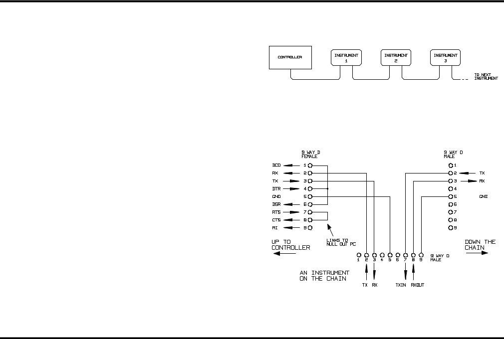
The 9-way D-type serial interface connector is located on the instrument rear panel. The pin connections are as shown below:
Pin |
Name |
Description |
1 |
- |
No internal Connection |
2 |
TXD |
Transmitted data from TF830 |
3 |
RXD |
Received data to TF830 |
4 |
- |
No internal connection |
5 |
GND |
Signal ground |
6 |
- |
No internal connection |
7 |
RXD2 |
Secondary received data (see diagram) |
8 |
TXD2 |
Secondary transmitted data (see diagram) |
9 |
GND |
Signal ground |
Pins 2, 3 and 5 may be used as a conventional RS232 interface with XON/XOFF handshaking. Pins 7, 8 and 9 are additionally used when the instrument is connected to the ARC interface.
1

Using a simple cable assembly, a ‘daisy chain’ connection system between any number of instruments, up to the maximum of 32 can be made, as shown below:
The daisy chain consists of the transmit data (TXD), receive date (RXD) and signal ground lines only. There are no control/handshake lines. This makes XON/XOFF protocol essential and allows the interconnection between instruments to contain just 3 wires. The wiring of the adaptor cable is shown below:
Addressable RS232 Chain (ARC) Wiring Scheme
All instruments on the interface must be set to the same baud rate and all must be powered on, otherwise instruments further down the daisy chain will not receive any data or commands.
The ARC standard for the other interface parameters is as follows, and in most instruments they are fixed.
Start bits |
1 |
Data bits |
8 |
Parity |
None |
Stop bits |
1 |
TF830 ADDRESS AND BAUD RATE SELECTION
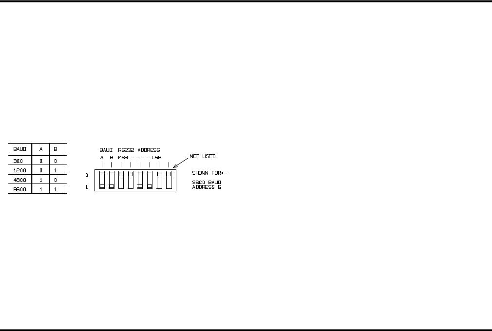
Each instrument connected to the ARC bus must be assigned a unique address and all must be set to the same baud rate. For the TF830 the address and baud rate are selected by the set of 8 dip switches on the rear panel. The switch functions are as shown below:
ARC PROTOCOL
Protocol Specification
Because of the need for XON/XOFF handshake it is possible to send ASCII coded data only; binary blocks are not allowed. Bit 7 of ASCII codes is ignored, i.e. assumed to be low. No distinction is made between upper and lower case characters in command mnemonics and they may be freely mixed. The ASCII codes below 20H (space) are reserved for interface control.
Interface Control Codes
All instruments intended for use on the ARC bus use the following set of interface control codes. Codes between 00H and 1FH which are not listed here as having a particular meaning are reserved for future use and will be ignored. Mixing interface control codes inside instrument
2

commands is not allowed except as stated below for CR and LF codes and XON and XOFF codes.
When an instrument is first powered on it will automatically enter the NonAddressable mode. In this mode the instrument is not addressable and will not respond to any address commands. This allows the instrument to function as a normal RS232 controllable device. This mode may be locked by sending the Lock Non-Addressable mode control code 04H (LNA). The controller and instrument can now freely use all 8 bit codes and binary blocks but all interface control codes are ignored. To return to addressable mode the instrument must be powered off.
To enable addressable mode after a instrument has been powered on the Set Addressable Mode control code, 02h (SAM), must be sent. This will then enable all instruments connected to the ARC bus to respond to all interface control codes. To return to Non-Addressable mode the Lock Non-Addressable mode control code must be sent which will disable addressable mode until the instruments are powered off.
Before an instrument is sent a command it must be addressed to listen by sending the Listen Address control code, 12H (LAD), followed by a single character which has the lower 5 bits corresponding to the unique address of the required instrument, e.g. the codes A-Z or a-z give the addresses 1-26 inclusive while @ is address 0 and so on. Once addressed to listen the instrument will read and act upon any commands sent until the listen mode is cancelled.
Because of the asynchronous nature of the interface it is necessary for the controller to be informed that an instrument has accepted the listen address sequence and is ready to receive commands. The controller will therefore wait for code 06H (ACK) before sending any commands, The addressed instrument will provide this ACK. The controller should time-out and try again if no ACK is received within 5 seconds.
Listen mode will be cancelled by any of the following interface control codes being received:
12H |
LAD |
Listen Address followed by an address not |
|
|
belonging to this instrument. |
14H |
TAD |
Talk Address for any instrument. |
03H |
UNA |
Universal Unaddress control code. |
04H |
LNA |
Lock Non-Addressable mode control code. |
18H |
UDC |
Universal Device Clear. |
Before a response can be read from an instrument it must be addressed to talk by sending the Talk Address control code, 14H (TAD) followed by a single character which has the lower 5 bits corresponding to the unique address of the required instrument, as for the listen address control code above. Once addressed to talk the instrument will send the response message it has available, if any, and then exit the talk addressed state. Only one response message will be sent each time the instrument is addressed to talk.
Talk mode will be cancelled by any of the following interface control codes being received:
12H |
LAD |
Listen Address for any instrument. |
14H |
TAD |
Talk Address followed by an address not be- |
|
|
longing to this instrument. |
03H |
UNA |
Universal Unaddress control code. |
04H |
LNA |
Lock Non-Addressable mode control code. |
18H |
UDC |
Universal Device Clear. |
Talk mode will also be cancelled when the instrument has completed sending a response message or has nothing to say.
The interface code 0AH (LF) is the Universal Command and response Terminator (UCT); it must be the last code sent in all commands and will be the last code sent in all responses.
The interface code 0DH (CR) may be used as required to aid the formatting of commands; it will be ignored by all instruments. Most instruments will terminate responses with CR followed by LF.
The interface code 13H (XOFF) may be sent at any time by a listener (instrument or controller) to suspend the output of a talker. The listener must send 11H (XON) before the talker will resume sending. This is the only form of handshake control supported by ARC.
3

Interface Control Code List
02H |
SAM |
Set Addressable mode. |
03H |
UNA |
Universal Unaddress control code. |
04H |
LNA |
Lock Non-Addressable mode control code. |
06H |
ACK |
Acknowledge that listen address received. |
0AH |
UCT |
Universal Command and response Terminator. |
0DH |
CR |
Formatting code, otherwise ignored. |
11H |
XON |
Restart transmission. |
12H |
LAD |
Listen Address - must be followed by an ad- |
|
|
dress belonging to the required instrument. |
13H |
XOFF |
Stop transmission. |
14H |
TAD |
Talk Address - must be followed by an address |
|
|
belonging to the required instrument. |
18H |
UDC |
Universal Device Clear. |
TF830 Command Formats
Serial input to the instrument is buffered in a 16 byte input queue which is filled, under interrupt, in a manner transparent to all other instrument operations. The instrument will send XOFF when approximately 8 characters are in the queue. XON will be sent when the queue has been emptied. This queue contains raw (un-parsed) data which is taken, by the parser, as required. Commands (and queries) are executed in order and the parser will not start a new command until any previous command or query is complete. There is no output queue which means that the response formatter will wait, indefinitely if necessary, until the instrument is addressed to talk and the complete response message has been sent. Due to the very short input queue available in the TF830 it is essential to read the response to any query before any new commands or queries are sent. This will ensure that a deadlock state (where the input queue is full and the TF830 is not emptying it because it is waiting to send a response) cannot occur.
Commands are sent as <PROGRAM MESSAGES> by the controller, each message consists of zero or more <PROGRAM MESSAGE UNIT> elements separated by <PROGRAM MESSAGE UNIT SEPARATOR> elements.
<PROGRAM MESSAGES> are separated by <PROGRAM MESSAGE TERMINATOR> elements which consist of the new line character (0AH).
A <PROGRAM MESSAGE UNIT SEPARATOR> is the semi-colon character ‘;’ (3BH).
A <PROGRAM MESSAGE UNIT> is any of the commands in the following sections.
Responses from the instrument to the controller are sent as <RESPONSE MESSAGES>. A <RESPONSE MESSAGE> consists of one <RESPONSE MESSAGE UNIT> followed by a <RESPONSE MESSAGE TERMINATOR>.
A <RESPONSE MESSAGE TERMINATOR> is the carriage return character followed by the new line character (0DH 0AH). The CR character is optional and may not be sent by all instruments.
Each query produces a specific <RESPONSE MESSAGE> which is listed along with the command in the following sections.
<WHITE SPACE> is ignored except in command identifiers. e.g. ‘X Z’ is not equivalent to ‘XZ’. <WHITE SPACE> is defined as character codes 00H to 20H inclusive with the exception of the ARC interface codes listed above.
The high bit of all characters is ignored.
The commands are case insensitive.
The command sections use the following nomenclature:
<pmt> |
<PROGRAM MESSAGE TERMINATOR>. |
<rmt> |
<RESPONSE MESSAGE TERMINATOR>. |
<n> |
A single digit number. |
<nrf> |
A number in any format e.g. 12, 12.00, 1.2 e1 |
|
and 120 e-1 are all accepted as the number 12. |
|
Any number, when received, is converted to the |
|
required precision consistent with the use, then |
|
rounded up to obtain the value of the com- |
|
mand. |
<nr1> |
A number with no fractional part, ie. an integer. |
<nr2> |
A number in fixed point format, e.g. 11.52, 0.78 |
|
etc. |
4

TF830 REMOTE/LOCAL OPERATION
At power-on the instrument will be in the local state with the REMOTE LED off. In this state all front panel operations are possible. When the instrument is addressed to listen and a command is sent the remote state will be entered and the REMOTE LED will be turned on. In this state the front panel is locked out and remote commands only will be processed. The instrument may be returned to the local state by holding down the RESET key and pressing the RANGE key; however, the effect of this action will remain only until the instrument is addressed again or receives another character from the ARC interface, when the remote state will once again be entered.
TF830 REMOTE COMMANDS
Because of the use of a four bit microcontroller the command parser uses only the lower four bits of the characters sent over the serial interface. This means that many combinations of character will be accepted for each command. Only one combination is given below and this is the one that is most obvious. For example. the RESET command is R<pmt> but 2<pmt> or b<pmt> will also work. The hex value given along with each command is the four bit code which is passed to the parser. Control characters are significant in all 8 bits and do not have alternatives. Responses from the TF830 are correctly formatted as 8 bit ASCII character codes, and are terminated with CR/LF.
Note that each command is completely executed before the next command is started.
SPACE character (0h) No Operation.
The command is ignored.
R (2h) Reset.
Performs the same operation as pressing the front panel RESET key under the same conditions.
S? |
(3h Fh) |
Status Query. |
Reads and returns the instrument status. The response is sent immediately, if in non-addressable mode, or when addressed to talk, if in addressable mode. The response is:-
xy<rmt>
Where x and y are numeric digits expressed in ASCII format. The first digit is the status byte and is a bit significant value in the range 0 to 7. The meaning of each bit is as follows:-
bit 0 External standard connected.
bit 1 An error has occurred. The error number follows.
bit 2 Triggered. A continuously updated bit indicating that an input signal has been detected. At frequencies below 20Hz this bit may toggle and may therefore not give a reliable indication of the triggered condition.
The second byte contains the error number of the last error that occurred. The value is cleared to zero after each status query. Error numbers are as follows:-
0No error has occurred since the last status query.
1A command syntax error - one or more commands ignored.
2Terminator missing - command ignored.
TC |
(4h |
3h) |
Trigger level to centre position. |
TN |
(4h |
Eh) |
Trigger level to negative pulse position. |
TP |
(4h |
0h) |
Trigger level to positive pulse position. |
This group of commands are used to set the trigger level to one of the three preset positions. Centre is equivalent to the trigger level control in the mid position. Negative pulse and positive pulse are equivalent to the extreme anti-clockwise and clockwise positions, respectively, of the trigger level control. For more information on trigger level see the section on Trigger Level Control. The trigger level is set irrespective of the position of the front panel control. When remote state is first entered the trigger level is set to centre. When remote state is cleared the trigger level reverts to the setting of the front panel control.
E? |
(5h Fh) |
Every Result Query. |
N? |
(Eh Fh) |
Next Result Query. |
? |
(Fh) |
Current Result Query. |
This group of commands return the results of measurements to the controller. The response is sent immediately, if in non-addressable mode, or when addressed to talk, if in addressable mode. The ? form
5

returns the display contents at the time the query is received. The N? form waits for the measurement in progress to finish then returns the display contents. The E? form is similar to the N? form except that the display contents are returned after each measurement until any new command is inserted into the input queue. In non-addressable mode the responses are sent continuously. In addressable mode one response is sent each time that the TF830 is addressed to talk. It is the ‘address to talk’ which selects which is the ‘measurement in progress’ and hence the reading returned is always as up to date as possible.
The format of the response is the same for all forms of the query and is as follows:-
xNNNNN.NNNeSEuu<rmt>
where:-
x |
is the overflow digit (if zero a space is sent). |
NN.NNis the displayed answer with the decimal point in the corresponding position (9 characters).
e |
is the letter e for exponent. |
S |
is a plus or minus sign indicating the sign of the exponent. |
Eis the exponent value to give the answer in Hz or seconds (1 character).
uuis the units specifier Hz or s_ or _ _. Each _ is a space (2 characters)
<rmt> is the terminator CR LF.
If there is nothing to measure and the display is zero the response will be:-
_00000000.e+0_ _<rmt>
F<n> (6h 1h-7h) Function n.
Sets the measurement function to the number <n>. The functions are numbered from 1 to 7 from left to right as they appear on the front panel. Hence F1 will select PERIOD A, F2 will select FREQUENCY A etc. The new function is selected immediately and a new measurement is started.
FI |
(6h 9h) |
Filter In (on). |
FO |
(6h Fh) |
Filter Out (off). |
Sets the low pass filter in or out. The filter is set irrespective of the position of the front panel switch. When remote state is first entered the filter is set to the state corresponding to the switch position. When remote state is cleared the filter reverts to the setting of the front panel switch.
I? |
(9h Fh) |
Identify Query. |
Responds with the instrument identifier. The response is sent immediately, if in non-addressable mode, or when addressed to talk, if in addressable mode. The format of the response is:-
TF830<rmt>
L |
(Ch) |
Low frequency mode. |
Sets the VLF mode as described in the Instruction Manual.
M<n> (Dh 1h-3h) Measurement Time n.
Selects the measurement time to the number <n>. The measurement times are numbered from 1 to 3 from left to right as they appear on the front panel. Hence M1 will select 1s, M2 will select 1s and M3 will select 10s. The new measurement time is selected immediately and a new measurement is started.
Remote Command Summary
R |
(2h) |
Reset. |
|
S? |
(3h |
Fh) |
Status Query. |
TC |
(4h |
3h) |
Trigger level to centre position. |
TN |
(4h |
Eh) |
Trigger level to negative pulse position. |
TP |
(4h |
0h) |
Trigger level to positive pulse position. |
E? |
(5h |
Fh) |
Every Result Query. |
N? |
(Eh Fh) |
Next Result Query. |
|
? |
(Fh) |
Current Result Query. |
|
F<n> |
(6h |
1h-7h) |
Function n. |
FI |
(6h |
9h) |
Filter In (on). |
FO |
(6h |
Fh) |
Filter Out (off). |
I? |
(9h |
Fh) |
Identify Query. |
L |
(Ch) |
Low frequency mode. |
|
M<n> |
(Dh 1h-3h) |
Measurement Time n. |
|
SPACE character |
(0h) No Operation. |
||
6
INTRODUCTION
L’interface ARC permet la connexion d’une série d’appareils, jusqu’à un maximum de 32, à une seule interface série sur un PC ou autre système informatique; chaque appareil peut alors être adressé séparément de telle sorte que les commandes pour cet appareil peuvent être transmises et ignorées par tous les autres appareils branchés sur l’interface. De plus, les appareils ARC peuvent être utilisés sur une simple interface RS232 en mode non-adressable sans modification.
Le logiciel ARCTALK est aussi offert en option pour les PC compatibles IBM. Sous sa forme la plus simple ARCTALK fournit le contrôle direct en temps réel des appareils sur le bus ARC depuis le clavier du PC. Toutefois, il peut être utilisé de manière plus efficace pour créer des ‘programmes’ complets permettant la configuration de plusieurs appareils et/ou la retransmission de mesures; les réponses peuvent être capturées dans un fichier ‘réponse’ pour une utilisation ultérieure, par exemple par une autre application qui pourrait générer un graphique à partir des données.
CONNEXIONS DE L’INTERFACE ARC
Le connecteur D à 9 broches de l’interface série est situé sur le panneau arrière de l’appareil. Les connexions sont les suivantes :
Broche |
Nom |
Description |
1 |
- |
Aucune connexion interne |
2 |
TXD |
Données transmises du TF830 |
3 |
RXD |
Données reçues par TF830 |
4 |
- |
Aucune connexion interne |
5 |
GND |
Prise de terre du système |
6 |
- |
Aucune connexion interne |
7 |
RXD2 |
Données reçues secondaires (voir schéma) |
8 |
TXD2 |
Données transmises secondaires (voir schéma) |
9 |
GND |
Prise de terre du système |
Les broches 2, 3 et 5 peuvent être utilisées en tant qu’interface RS232 conventionnelle avec l’établissement de liaison XON/XOFF (Reprendre/arrêter transmission). Les broches 7, 8 et 9 sont aussi utilisées lorsque l’appareil est branché sur l’interface ARC.
En utilisant un assemblage de câbles simple, un système de connexion ‘en chaîne bouclée’ entre plusieurs appareils peut être fait, jusqu’à un maximum de 32, comme cela est indiqué ci-dessous :
La chaîne bouclée comprend les connexions transmission de données (TXD), réception de données (RXD) et prise de terre uniquement. Il n’y a pas de connexions contrôle/établissement de liaison. Ceci rend l’établissement de liaison XON/XOFF essentiel, et permet à l’interconnexion entre appareils de ne contenir que 3 fils. Le câblage du câble de l’adaptateur est indiqué ci-dessus :
Tous les appareils branchés sur l’interface doivent être mis sur la même vitesse de transmission et tous doivent être mis sous tension, sinon les appareils en aval de la chaîne bouclée ne recevront aucune donnée et aucune commande.
7
Le standard ARC pour les autres paramètres de l’interface est le suivant, et dans la plupart des appareils ceux-ci sont fixes.
Bits de départ |
1 |
Bits de données |
8 |
Parité |
Aucune |
Bits d’arrêt |
1 |
SELECTION D’ADRESSE ET DE
VITESSE DE TRANSMISSION DU TF830
Chaque appareil branché sur le bus ARC doit avoir une adresse unique et ils doivent tous être mis sur la même vitesse de transmission. Pour le TF830 l’adresse et la vitesse de transmission sont choisies par la série de 8 commutateurs DIP située sur le panneau arrière. Les fonctions des commutateurs sont indiquées ci-dessous :
PROTOCOLE ARC
Spécification du protocole
En raison de la nécessité de l’établissement de liaison XON/XOFF il n’est possible de transmettre que des données ASCII; les bloc binaires ne sont pas permis. Le bit 7 des codes ASCII est ignoré. Aucune distinction n’est faite entre les caractères majuscules et minuscules en mnémonique de commande et ils peuvent être mélangés entre eux. Les codes ASCII ci-dessous 20H (espace) sont réservés au contrôle de l’interface.
Codes de contrôle d’interface
Tous les appareils destinés à être utilisés sur le bus ARC utilisent la série de codes de contrôle d’interface ci-dessous. Les codes entre 00H et
1FH qui ne sont pas inclus dans cette liste, sont réservés à une utilisation ultérieure et seront ignorés. Il n’est pas permis de mélanger les codes de contrôle d’interface à l’intérieur des commandes d’appareils, sauf dans les cas ci-dessous pour les codes CR (retour de chariot) et LF (saut de ligne) et XON et XOFF.
Lorsqu’un appareil est allumé pour la première fois, il se mettra automatiquement en mode Non-adressable. Dans ce mode l’appareil n’est pas adressable et ne réagira à aucune commande d’adresse. Ceci permet à l’appareil de fonctionner en tant qu’appareil RS232 normal contrôlable. Ce mode peut être verrouillé en envoyant le code de contrôle 04H du mode Lock Non-addressable (LNA) (verrouillé non-adressable). Le contrôleur et l’appareil peuvent maintenant utiliser librement tous les codes 8 bits et blocs binaires mais tous les codes de contrôle d’interface sont ignorés. Pour revenir en mode adressable l’appareil doit être éteint.
Pour valider le mode adressable après qu’un appareil ait été mis en marche le code de contrôle Set Addressable Mode (Mise en mode adressable), 02H (SAM), doit être envoyé. Ceci permettra à tous les appareils connectés au bus ARC de répondre à tous les codes de contrôle d’interface. Pour revenir au mode Non-adressable le code de contrôle Lock Non-addressable doit être envoyé, celui-ci désarmera le mode adressable jusqu’à ce que les appareils soient éteints.
Avant d’envoyer une commande à un appareil celui-ci doit être mis en état d’écoute en envoyant le code de contrôle Listen Address (Adresse d’écoute) 12H (LAD), suivi d’un seul caractère qui a les 5 bits de rang inférieur correspondants à l’adresse unique de l’appareil en cause, exemple, les codes A-Z ou a-z donnent les adresses 1-26 inclus alors que @ est l’adresse 0 et ainsi de suite. Une fois mis en état d’écoute l’appareil lira et réagira à toutes les commandes envoyées jusqu’à ce le mode écoute soit annulé.
En raison de la nature asynchrone de l’interface il est nécessaire que le contrôleur soit informé qu’un appareil a accepté la séquence Listen Address et est prêt à recevoir des commandes. Le contrôleur devra donc attendre de recevoir le code 06h (ACK) (accuser réception) avant d’avoir des commandes. L’appareil adressé fournira cet ACK. Si aucun code ACK n’est reçu au bout de 5 secondes, le contrôleur doit tem-
8

poriser et ré-essayer. Le mode écoute sera annulé par l’un quelconque des codes de contrôle d’interface ci-dessous :
12H |
LAD |
Listen Address suivi d’une adresse qui n’ap- |
|
|
partient pas à cet appareil |
14H |
TAD |
Talk Address (Adresse de dialogue) pour tout |
|
|
appareil |
03H |
UNA |
Code de contrôle Universal Unaddress (Fin |
|
|
d’adresse universelle) |
04H |
LNA |
Code de contrôle de mode Lock Non-address- |
|
|
able |
18H |
UDC |
Universal Device Clear |
|
|
(Libération d’appareil universelle) |
Avant qu’une réponse puisse être lue en provenance d’un appareil, celui-ci doit être mis en état de communiquer par l’envoi du code de contrôle Talk Address, 14H (TAD), suivi d’un seul caractère dont les 5 bits de rang inférieur correspondent à l’adresse unique de l’appareil en cause, comme pour le code de contrôle de l’adresse d’écoute. Une fois mis en état de communiquer l’appareil enverra le message de réponse disponible, s’il y en a, puis quittera l’état Talk Address. Un seul message de réponse sera envoyé à chaque fois que l’appareil est mis en état de dialogue.
Le mode Talk sera annulé par la réception de l’un quelconque des codes de contrôle d’interface ci-dessous:
12H |
LAD |
Listen Address pour tout appareil |
14H |
TAD |
Talk Address suivi d’une adresse qui n’appar- |
|
|
tient pas à cet appareil |
03H |
UNA |
Code de contrôle Universal Unaddress |
04H |
LNA |
Code de contrôle de mode Lock Non-address- |
|
|
able |
18H |
UDC |
Universal Device Clear |
Le mode Talk sera aussi annulé lorsque l’appareil a fini d’envoyer un message de réponse ou n’a plus rien à dire.
Le code d’interface 0AH (LF) est la Commande universelle et Fin de réponse (UCT); celui-ci doit être le dernier code transmis dans toutes
les commandes et sera le dernier code transmis dans toutes les réponses.
Le code d’interface 0DH (CR) peut être utilisé selon les besoins pour aider dans le formatage des commandes; il sera ignoré par tous les appareils. La plupart des appareils termineront leurs réponses avec CR suivi de LF.
Le code d’interface 13h (XOFF) peut être transmis à tout moment par un écouteur (appareil ou contrôleur) pour suspendre le signal de sortie de l’émetteur. L’écouteur doit envoyer 11H (XON) avant que l’émetteur reprenne la transmission. Ceci est le seul type de contrôle d’établissement de liaison supporté par ARC.
Liste des codes de contrôle d’interface
02H |
SAM |
Set Addressable Mode |
03H |
UNA |
Code de contrôle Universal Unaddress |
04H |
LNA |
Code de contrôle de mode Lock Non-address- |
|
|
able |
06H |
ACK |
Accusé réception du code Listen Address |
0AH |
UCT |
Fin de commande et de réponse universel |
0DH |
CR |
Code de formatage, ignoré autrement |
11H |
XON |
Reprendre transmission |
12H |
LAD |
Listen Address - doit être suivi d’une adresse |
|
|
qui appartient à l’appareil désiré |
13H |
XOFF |
Arrêt de transmission |
14H |
TAD |
Talk Address - doit être suivi d’une adresse qui |
|
|
appartient à l’appareil désiré |
18H |
UDC |
Universal Device Clear |
Formats de commande du TF830
L’entrée séquentielle à l’appareil est en tampon dans une file d’attente d’entrée 16 multiplets qui est remplie, avec interruption, d’une manière transparente à toutes les autres opérations de l’appareil. L’appareil transmettra XOFF lorsqu’il y a environ 8 caractères dans la file d’attente. XON sera transmis lorsque la file d’attente aura été vidée. Cette file d’attente contient des données brutes (non-analysées) qui sont prises,
9
 Loading...