


 Loading...
TG1010
Programmable 10 MHz
DDS Function Generator
User Manual
Manual Copyright © 1994 T T Instruments Ltd. All rights reserved.
Software Copyright © 1994 T T Instruments Ltd. All rights reserved.
Book Part Number 48591 - 0440 Issue 4

Table of Contents |
|
Introduction |
2 |
Specifications |
4 |
Safety |
9 |
EMC |
10 |
Installation |
11 |
Connections |
12 |
Front Panel Connections |
12 |
Rear Panel Connections |
12 |
General Operation |
14 |
Main Generator Operation |
17 |
Main Generator Parameters |
17 |
Warning and Error Messages |
20 |
Auxiliary Output |
22 |
Waveform Generation Options |
22 |
Sweep Operation |
25 |
Triggered Burst and Gate |
28 |
Triggered Burst |
28 |
Gated Mode |
30 |
Amplitude Modulation |
31 |
FSK |
33 |
Special Waveforms |
34 |
Staircase |
34 |
Arbitrary |
34 |
Noise |
36 |
HOP |
37 |
System Operations |
39 |
Storing and Recalling Set-ups |
39 |
System Settings |
39 |
Synchronising Generators |
41 |
Calibration |
43 |
Application Examples |
45 |
DDS Operation and Further Waveform Considerations |
49 |
Remote Operation |
52 |
Remote Commands |
62 |
Remote Command Summary |
69 |
Appendix 1. Warning and Error Messages |
72 |
Appendix 2. Factory System Defaults |
74 |
Appendix 3. Instructions for using TG1010 with WaveForm DSP |
74 |
Appendix 4. Application Information Notes |
76 |
Appendix 5. Calibration Password |
78 |
1

Introduction
This Programmable Function Generator uses direct digital synthesis to provide high performance and extensive facilities at a breakthrough price. It can generate a variety of waveforms between 0.1mHz and 10MHz with a resolution of 7 digits and an accuracy better than 10ppm.
Direct digital synthesis for accuracy & stability
Direct digital synthesis (DDS) is a technique for generating waveforms digitally using a phase accumulator, a look-up table and a DAC. The accuracy and stability of the resulting waveforms is related to that of the crystal master clock.
The DDS generator offers not only exceptional accuracy and stability but also high spectral purity, low phase noise and excellent frequency agility.
A wide range of waveforms
High quality sine, square and pulse waveforms can be generated over the full frequency range of 0.1mHz to 10MHz.
Triangle waveforms, ramp waveforms and multi-level squarewaves can also be generated but with limitations as to the maximum useable frequencies.
Variable symmetry/duty-cycle is available for all standard waveforms.
Arbitrary waveform capability
Arbitrary waveforms can be loaded via the digital interfaces and then used in a similar way to the standard waveforms.
Up to five arbitrary waveforms of 1024 10-bit words can be stored in non-volatile memory. The waveform clock is 27.48MHz maximum.
This facility considerably expands the versatility of the instrument making it suitable for the generation of highly complex waveform patterns.
In addition, numerous “complex” waveforms are pre-defined in ROM, including commonly used waveshapes such as sinex/x, exponentially decaying sinewave, etc. Further waveshapes will be added to the library in response to customer requests.
Sweep
All waveforms can be swept over their full frequency range at a rate variable between 10 milliseconds and 15 minutes. The sweep is fully phase continuous.
Sweep can be linear or logarithmic, single or continuous. the front panel, the trigger input, or the digital interfaces.
Single sweeps can be triggered from Two sweep markers are provided.
AM
Amplitude Modulation is available for all waveforms and is variable in 1% steps up to 100%. An internal AM source is incorporated. Alternatively modulation can be controlled from an external generator.
FSK
Frequency Shift Keying provides phase coherent switching between two selected frequencies at a rate defined by the switching signal source.
The rate can be set from dc to 50kHz internally, or dc to 1MHz externally.
Trigger/Burst & Gated
All waveforms are available as a triggered burst whereby each positive edge of the Trigger signal will produce one burst of the carrier, starting and stopping at the phase angle specified by the start-stop phase setting.
2

The number of cycles in the burst can be set between 0.5 and 1023. The Gated mode turns the output signal On when the gating signal is high and Off when it is low.
Both Triggered and Gated modes can be operated from the internal Trigger Generator (0.005Hz to 50kHz) or from an external source (dc to 1MHz).
Waveform Hop & Noise
The generator can be set up to ‘hop’ between a number of different waveform set-ups either at a pre-determined rate or in response to a manual trigger.
Up to 16 different hop waveforms can be defined in terms of frequency, amplitude, function, offset and duration, which is variable in 1ms steps up to 60s. The generator can also be set to simulate random noise within the bandwidth .03Hz to 700kHz with adjustable amplitude and offset.
Multiple phase-locked generators
The signals from the Clock In/Out socket and the Sync Out socket can be used to phase lock two or more generators.
This can be used to generate multi-phase waveforms or locked waveforms of different frequencies.
Easy and convenient to use
All of the main generator parameters are clearly displayed together on a backlit LCD with 4 rows of 20 characters. Sub menus are used for the modulation modes and other complex functions.
All parameters can be entered directly from the numeric keypad. Alternatively most parameters can be incremented or decremented using the rotary encoder.
This system combines quick and easy numeric data entry with quasi-analogue adjustment when required.
Fully programmable
Addressable RS-232 standard, GPIB optional
The generator has an RS-232 interface as standard which can be used for remote control of all of the instrument functions or for the down-loading of arbitrary waveforms.
As well as operating as a conventional RS-232 interface, it can also be used in addressable mode whereby up to 32 instruments can be linked to one PC serial port as part of a TTi “ARC” system.
Alternatively, a GPIB interface conforming to IEEE-488.2 is available as an option.
3

Specifications
Specifications apply at 18°-28°C after one hour warm-up, at maximum output into 50Ω
FREQUENCY
Range: |
0.1 mHz to 10 MHz. |
|
All waveforms are available up to 10 MHz. However, the purity of |
|
triangle, ramp and multi-level squarewave waveforms is not |
|
specified above the frequencies indicated in the appropriate |
|
WAVEFORM section. In Arbitrary mode all waveform points are |
|
continuously output up to approximately 27 kHz beyond which |
Resolution: |
they are sampled. |
0.1mHz (7 digits) |
|
Accuracy: |
Typically ± 10 ppm for 1 year, 18°C to 28°C |
Temperature Stability: |
Typically <1 ppm/°C |
SYMMETRY
Range: |
Sine, Triangle, Ramp - 1% to 99% at all frequencies |
Resolution: |
Squarewave,Pulse - 1% to 99% to 30kHz, 20% to 80% to 10MHz. |
0.1% |
WAVEFORMS
Sine, square, positive pulse, negative pulse, multi-level squarewave, triangle, ramp up, ramp down, DC, ARB and Noise.
Sinewave |
|
Output level: |
5mV to 20V p-p open circuit o/p. |
Harmonic Distortion: |
<0.3% THD to 500kHz; |
|
<-60dBc to 20kHz; <-50dBc to 1MHz; <-35dBc to 10MHz. |
Non-harmonic Spurii: |
<-55dBc to 7MHz; <-50dBc to 10MHz. |
Squarewave |
|
Output level: |
5mV to 20V p-p open circuit o/p. |
Rise and Fall Times: |
<25ns |
Triangle |
|
Output level: |
5mV to 20V p-p open circuit o/p. |
Linearity error: |
<0.5% to 30 kHz |
Positive and Negative Ramp |
|
Output level: |
5mV to 20V p-p open circuit o/p. |
Linearity error: |
<0.5% to 30 kHz |
Positive and Negative Pulse |
|
Output level: |
2.5mV to 10V p-p open circuit o/p. |
Rise and Fall Times: |
<25ns |
Multi-Level Squarewave |
|
Up to 16 steps available per cycle, each step selectable for amplitude (10 bit resolution) and duration (1 to 1024 samples). Allows generation of 3 level squarewave, staircase, multiplexed LCD driver signals etc.
Frequency Range: |
All waveform points can be continuously output up to |
|
approximately 27kHz, above which sampling will introduce a 1 |
|
clock edge uncertainty (1 clock = 36ns). |
Output level: |
5mV to 20V p-p open circuit o/p. |
Rise and Fall Times: |
<25ns |
4

Arbitrary
A number of frequently required waveforms are pre-programmed in ROM. Alternatively, waveforms can be downloaded via the generator’s RS232 or GPIB interfaces and stored in nonvolatile RAM.
Frequency range: |
All waveform points can be continuously output up to |
|
approximately 27 kHz, above which they are sampled. |
Output level: |
5mV to 20V p-p open circuit o/p. |
Number of samples: |
1024 |
Sample levels: |
1024 (10 bits) |
HOP
Up to 16 different waveforms can be output in sequence at a rate determined by either the internal timer, an external trigger a remote command, or from the keyboard. Each waveform can be set to any waveshape (except noise), frequency, amplitude and offset. Frequency only changes are phase-continuous.
Noise
White noise output with a typical -3dB bandwidth of 0.03Hz to 700kHz. Amplitude and offset adjustable. Noise can only be used with Gated and AM modulation modes.
MODULATION MODES
Trigger/Burst
Phase coherent signal keying - each positive edge of the trigger signal will produce one burst of the carrier, starting and stopping at the phase angle specified by the Start/Stop phase setting.
Carrier frequency: |
0.1mHz to at least 1MHz |
Carrier waveforms: |
All. |
Number of cycles: |
1 to 1023 (resolution 1 cycle) or 0.5 to 511.5 (resolution 0.5 |
|
cycle). |
Trigger rep. rate: |
dc to 50 kHz internal, dc to 1MHz external. |
Source: |
Internal from keyboard or trigger generator. External from EXT |
|
TRIG input or remote interface. |
Gated |
|
Non-phase coherent signal keying - output carrier wave is on while Gate signal is high and off |
|
while low. |
|
Carrier frequency: |
From 0.1 mHz to 10 MHz. |
Carrier waveforms: |
All |
Trigger rep. rate: |
dc to 50 kHz internal, dc to 1 MHz external. |
Gate signal source: |
Internal from keyboard or trigger generator. External from EXT |
|
TRIG input or remote interface. |
Sweep |
|
Carrier Waveforms: |
All |
Sweep Mode: |
Linear or logarithmic, single or continuous. |
Sweep Width: |
From 0.1 mHz to 10 MHz in one range. Phase continuous. |
|
Independent setting of the start and stop frequency. |
Sweep Time: |
10ms to 999s (3 digit resolution). |
Markers: |
Two, variable during sweep. Available at the rear panel |
|
TRIG/SWEEP OUT socket. |
Sweep Trigger source: |
The sweep may be free run or triggered from any of the following |
|
sources: Internal from keyboard. External from EXT TRIG input |
|
or remote interface. |
Amplitude Modulation
Carrier frequency: |
From 0.1mHz to 10 MHz. |
|
5 |

Carrier waveforms: |
All. |
Depth: |
Variable 0 to 100% typical, resolution 1%. |
Internal source: |
1 kHz fixed sinewave or 0.005 Hz to 50 kHz squarewave. |
External: |
See VCA In |
Frequency Shift Keying (FSK)
Phase coherent switching between two selected frequencies at a rate defined by the switching signal source.
Carrier frequency: |
From 0.1mHz to 10 MHz. |
Carrier waveforms: |
All. |
Switch repetition rate: |
dc to 50 kHz internal, dc to 1 MHz external. |
Switching signal source: |
Internal from keyboard or trigger generator. External from EXT |
|
TRIG input or remote interface. |
Start/Stop Phase
Carrier frequency: |
0.1 mHz to at least 1MHz. |
Carrier waveforms: |
All. |
Range: |
-360 to +360 degrees. |
Resolution: |
1 degree. |
Accuracy: |
Typically 1 degree to 30 kHz. |
Trigger Generator |
|
Internal source 0.005 Hz to 50 kHz squarewave adjustable in 20µs steps. 3 digit resolution. Available for external use from TRIG/SWEEP OUT socket.
OUTPUTS
Main Output
Output Impedance:
Amplitude:
50Ω or 600Ω
5mV to 20V pk-pk open circuit, (2.5mV to 10V pk-pk into 50Ω/600Ω). Output can be specified as EMF (open circuit value) or P.D (potential difference) in pk-pk, r.m.s. or dBm.
Amplitude Accuracy: |
typically ±3% ±1mV at 1kHz into 50Ω/600Ω. |
Amplitude Flatness: |
±0.2dB to 200 kHz; ±1dB to 5 MHz; ±2.5dB to 10 MHz. |
DC Offset Range: |
±10V. DC offset plus signal peak limited to ±10V from 50Ω/600Ω. |
DC Offset Accuracy: |
typically ±3% ±10mV, unattenuated. |
Resolution: |
3 digits for both Amplitude and DC Offset. |
Pulse Aberrations: |
<5% + 2mV. |
Aux Out |
|
CMOS/TTL levels with symmetry and frequency of main output and phase of Start-Stop Phase setting.
Trig/Sweep Out
Multifunction output depending upon mode. Except in Sweep and HOP modes the output is that of the Trigger Generator at CMOS/TTL levels from 1kΩ. In Sweep mode the output is a 3-level waveform, changing from high (4V) to low (0V) at start of sweep, with narrow 1V pulses at each marker point. In HOP mode the output goes low at the entry to each step, followed by a rising edge after the frequency and waveshape have changed for the new step.
INPUTS
Ext Trig |
|
Frequency Range: |
DC - 1 MHz. |
Signal Range: |
Threshold nominally TTL level; maximum input ±10V. |
|
|
6 |
|

Minimum Pulse Width: |
50ns, for Trigger, Gate and FSK modes; 1ms for Sweep and |
Input Impedance: |
HOP modes. |
10kΩ |
|
VCA In |
|
Frequency Range: |
DC - 100 kHz. |
Signal Range: |
2.5V for 100% level change at maximum output. |
Input Impedance: |
typically 6kΩ. |
PHASE LOCKING
The signals from these sockets are used to phase lock two or more generators.
Clock In/Out
TTL/CMOS threshold level as an input. Output logic levels nominally 1V and 4V from typically 50Ω as an output.
Sync Out
TTL/CMOS logic levels from typically 50Ω.
INTERFACES
Full remote control facilities are available through the RS232 (standard) or optional GPIB interfaces.
RS232: |
Variable Baud rate, 9600 Baud maximum. 9-pin D-connector. |
|
Fully compatible with Thurlby-Thandar ARC (Addressable |
|
RS232 Chain) system. |
IEEE-488: |
Conforming with IEEE488.1 and IEEE488.2 |
GENERAL
Display: |
20 character x 4 row alphanumeric LCD. |
Data Entry: |
Keyboard selection of mode, waveform etc.; value entry direct by |
|
numeric keys or by rotary control. |
Stored Settings: |
Up to 9 complete instrument set-ups may be stored and recalled |
|
from battery-backed memory. |
Size: |
3U (130mm) height; half-rack (212mm) width; 330mm long. |
Weight: |
4.1kg. (9lb.) |
Power: |
100V AC, 110-120V AC or 220V-240V AC ±10%, 50/60Hz, |
|
adjustable internally; 30VA max. Installation Category II. |
Operating Range: |
+5°C to 40°C, 20-80% RH. |
Storage Range: |
-20°C to + 60°C. |
Environmental: |
Indoor use at altitudes up to 2000m, Pollution Degree 2. |
Options: |
IEEE-488 interface; 19 inch rack mounting kit. |
Safety: |
Complies with EN61010-1. |
EMC: |
Complies with EN61326. |
7

EC Declaration of Conformity
We Thurlby Thandar Instruments Ltd
Glebe Road
Huntingdon
Cambridgeshire PE29 7DR
England
declare that the
TG1010 DDS Function Generator with GPIB Option
meets the intent of the EMC Directive 89/336/EEC and the Low Voltage Directive 73/23/EEC. Compliance was demonstrated by conformance to the following specifications which have been listed in the Official Journal of the European Communities.
EMC |
|
|
|
|
Emissions: |
a) |
EN61326 (1998) |
Radiated, Class B |
|
|
b) |
EN61326 (1998) |
Conducted, Class B |
|
|
c) |
EN61326 (1998) |
Harmonics, referring to EN61000-3-2 (2000) |
|
Immunity: |
EN61326 (1998) Immunity Table 1, Performance B, referring to: |
|||
|
a) |
EN61000-4-2 (1995) Electrostatic Discharge |
||
|
b) |
EN61000-4-3 (1997) |
Electromagnetic Field |
|
|
c) |
EN61000-4-11 (1994) Voltage Interrupt |
||
|
d) |
EN61000-4-4 (1995) |
Fast Transient |
|
|
e) |
EN61000-4-5 (1995) |
Surge |
|
|
f) |
EN61000-4-6 (1996) |
Conducted RF |
|
Safety
EN61010-1 (1993) Installation Category II, Pollution Degree 2.
................................................................
CHRIS WILDING TECHNICAL DIRECTOR
2 July 2001
8

Safety
This function generator is a Safety Class I instrument according to IEC classification and has been designed to meet the requirements of EN61010-1 (Safety Requirements for Electrical Equipment for Measurement, Control and Laboratory Use). It is an Installation Category II instrument intended for operation from a normal single phase supply.
This instrument has been tested in accordance with EN61010-1 and has been supplied in a safe condition. This instruction manual contains some information and warnings which have to be followed by the user to ensure safe operation and to retain the instrument in a safe condition.
This instrument has been designed for indoor use in a Pollution Degree 2 environment in the temperature range 5°C to 40°C, 20% - 80% RH (non-condensing). It may occasionally be subjected to temperatures between +5°C and –10°C without degradation of its safety. Do not operate while condensation is present.
Use of this instrument in a manner not specified by these instructions may impair the safety protection provided. Do not operate the instrument outside its rated supply voltages or environmental range.
WARNING! THIS INSTRUMENT MUST BE EARTHED
Any interruption of the mains earth conductor inside or outside the instrument will make the instrument dangerous. Intentional interruption is prohibited. The protective action must not be negated by the use of an extension cord without a protective conductor.
When the instrument is connected to its supply, terminals may be live and opening the covers or removal of parts (except those to which access can be gained by hand) is likely to expose live parts. The apparatus shall be disconnected from all voltage sources before it is opened for any adjustment, replacement, maintenance or repair.
Any adjustment, maintenance and repair of the opened instrument under voltage shall be avoided as far as possible and, if inevitable, shall be carried out only by a skilled person who is aware of the hazard involved.
If the instrument is clearly defective, has been subject to mechanical damage, excessive moisture or chemical corrosion the safety protection may be impaired and the apparatus should be withdrawn from use and returned for checking and repair.
Make sure that only fuses with the required rated current and of the specified type are used for replacement. The use of makeshift fuses and the short-circuiting of fuse holders is prohibited.
This instrument uses a Lithium button cell for non-volatile memory battery back-up; typical life is 5 years. In the event of replacement becoming necessary, replace only with a cell of the correct type, i.e. 3V Li/Mn02 20mm button cell type 2032. Exhausted cells must be disposed of carefully in accordance with local regulations; do not cut open, incinerate, expose to temperatures above 60°C or attempt to recharge.
Do not wet the instrument when cleaning it and in particular use only a soft dry cloth to clean the LCD window. The following symbols are used on the instrument and in this manual:-
l
Caution -refer to the accompanying documentation, incorrect operation may damage the instrument.
terminal connected to chassis ground.
mains supply OFF.
mains supply ON.
alternating current.
9
EMC
This instrument has been designed to meet the requirements of the EMC Directive 89/336/EEC. Compliance was demonstrated by meeting the test limits of the following standards:
Emissions
EN61326 (1998) EMC product standard for Electrical Equipment for Measurement, Control and Laboratory Use. Test limits used were:
a)Radiated: Class B
b)Conducted: Class B
c)Harmonics: EN61000-3-2 (2000) Class A; the instrument is Class A by product category.
Immunity
EN61326 (1998) EMC product standard for Electrical Equipment for Measurement, Control and Laboratory Use.
Test methods, limits and performance achieved were:
a)EN61000-4-2 (1995) Electrostatic Discharge : 4kV air, 4kV contact, Performance A.
b)EN61000-4-3 (1997) Electromagnetic Field, 3V/m, 80% AM at 1kHz, Performance A.
c)EN61000-4-11 (1994) Voltage Interrupt, 1 cycle, 100%, Performance B*.
d)EN61000-4-4 (1995) Fast Transient, 1kV peak (AC line), 0.5kV peak (signal lines and RS232/GPIB ports), Performance A.
e)EN61000-4-5 (1995) Surge, 0.5kV (line to line), 1kV (line to ground), Performance A.
f)EN61000-4-6 (1996) Conducted RF, 3V, 80% AM at 1kHz (AC line only; signal connections <3m not tested), Performance A.
According to EN61326 the definitions of performance criteria are:
Performance criterion A: ‘During test normal performance within the specification limits.’
Performance criterion B: ‘During test, temporary degradation, or loss of function or performance which is self-recovering’.
Performance criterion C: ‘During test, temporary degradation, or loss of function or performance which requires operator intervention or system reset occurs.’
*Note: To achieve Performance B it is necessary to set the instrument such that 'power down' settings are restored at power up; set POWER UP = POWER DOWN on the SYStem settings menu.
Cautions
To ensure continued compliance with the EMC directive the following precautions should be observed:
a)connect the generator to other equipment using only high quality, double-screened cables.
b)after opening the case for any reason ensure that all signal and ground connections are remade correctly before replacing the cover. Always ensure all case screws are correctly refitted and tightened.
c)In the event of part replacement becoming necessary, only use components of an identical type, see the Service Manual.
10

Installation
Check that the instrument operating voltage marked on the rear panel is suitable for the local supply. Should it be necessary to change the operating voltage, proceed as follows:
1)Disconnect the instrument from all voltage sources.
2)Remove the screws which retain the top cover and lift off the cover.
3)Change the transformer connections as follows:
for 230V operation connect the live (brown) wire to pin 15 for 115V operation connect the live (brown) wire to pin 14 for 100V operation connect the live (brown) wire to pin 13
4)Refit the cover and the secure with the same screws.
5)To comply with safety standard requirements the operating voltage marked on the rear panel must be changed to clearly show the new voltage setting.
6)Change the fuse to one of the correct rating, see below.
Fuse
Ensure that the correct mains fuse is fitted for the set operating voltage. The correct mains fuse types are:
for 230V operation: |
250 mA (T) 250 V HRC |
for 100V or 115V operation: |
500 mA (T) 250 V HRC |
To replace the fuse, disconnect the mains lead from the inlet socket and release the fuse drawer below the socket pins by depressing both clips together, with miniature screwdrivers, so that the drawer can be eased open. Change the fuse and replace the drawer.
The use of makeshift fuses or the short-circuiting of the fuse holder is prohibited.
Mains Lead
When a three core mains lead with bare ends is provided it should be connected as follows:-
Brown |
- |
Mains Live |
Blue |
- |
Mains Neutral |
Green / Yellow |
- |
Mains Earth |
WARNING! THIS INSTRUMENT MUST BE EARTHED
Any interruption of the mains earth conductor inside or outside the instrument will make the instrument dangerous. Intentional interruption is prohibited. The protective action must not be negated by the use of an extension cord without a protective conductor.
Mounting
This instrument is suitable both for bench use and rack mounting. It is delivered with feet for bench mounting. The front feet include a tilt mechanism for optimal panel angle.
A rack kit for mounting one or two of these Half-width 3U high units in a 19” rack is available from the Manufacturers or their overseas agents.
11
Connections
Front Panel Connections
MAIN OUT
This is the 50Ω output from the main generator. It will provide up to 20V peak-to-peak e.m.f. which will yield 10V peak-to-peak into a matched 50Ω load. It can tolerate a short circuit for 60 seconds.
Do not apply external voltages to this output.
AUX OUT
This is a TTL/CMOS level output synchronous with MAIN OUT. Symmetry is the same as that set for the main output but the phase relationship between MAIN OUT and AUX OUT is determined by the PHASE setting specified on the TRIGger menu.
AUX OUT logic levels are nominally 0V and 5V from typically 50Ω. AUX OUT will withstand a short-circuit.
Do not apply external voltages to this output.
EXT TRIG
This is the external trigger input for Trigger, Gate, Sweep, FSK and HOP operating modes. It is also the input used to synchronise the generator (as a slave) to another (which is the master).
Do not apply external voltages exceeding ±10 V.
Rear Panel Connections
CLOCK IN/OUT
The function of the CLOCK IN/OUT socket is set from the SYStem menu as follows:
INPUT |
The socket becomes an input for an external clock. |
OUTPUT |
This is the default setting. The internal clock is made available at the |
|
socket. When two or more generators are synchronised the ‘master’ is |
|
set to OUTPUT and the signal is used to drive the CLOCK IN inputs of |
|
the slaves. |
PHASE LOCK |
When two or more generators are synchronised the slaves are set to |
|
PHASE LOCK. |
As an output the logic levels are nominally 1V and 4V from typically 50Ω. CLOCK OUT will withstand a short-circuit. As an input the thresholds is TTL/CMOS compatible.
Do not apply external voltages to this output exceeding +7.5 V or -2.5 V.
VCA IN
This is the input socket for external voltage controlled amplitude (VCA). Input impedance is nominally 6kΩ. Apply 2.5V for 100% level change at maximum output.
Do not apply external voltages exceeding ±10V.
12

SYNC OUT
When two or more generators are synchronised the SYNC OUT socket on the master generator is connected to the EXT TRIG inputs of slave generators.
SYNC OUT logic levels are nominally 0V and 5V from typically 50Ω. SYNC OUT will withstand a short-circuit.
Do not apply external voltages to this output.
TRIG/SWEEP OUT
The function of this output is automatically determined by the generator operating mode.
Except in sweep and HOP modes the output is that of the internal trigger generator, a fixed amplitude square-wave whose frequency is set on the TRIG or GATE menus. The rising edge of the trigger generator initiates trigger, burst, gate, etc.
In sweep mode the output is a 3-level waveform, changing from high (4V) to low (0V) at start of sweep, with narrow 1V pulses at each marker point.
In HOP mode the output goes low on entry to each waveform step and high after the new frequency and waveshape of that step have been set.
Output levels are nominally 0V and 4V from 1kΩ. TRIG/SWEEP OUT will withstand a shortcircuit.
Do not apply external voltages to this output.
RS232
9-pin D-connector compatible with the Thurlby Thandar ARC (Addressable RS232 Chain) system. The pin connections are shows below:
Pin |
Name |
Description |
1 |
- |
No internal Connection |
2 |
TXD |
Transmitted data from instrument |
3 |
RXD |
Received data to instrument |
4 |
- |
No internal connection |
5 |
GND |
Signal ground |
6 |
- |
No internal connection |
7 |
RXD2 |
Secondary received data |
8 |
TXD2 |
Secondary transmitted data |
9 |
GND |
Signal ground |
Pin 2, 3 and 5 may be used as a conventional RS232 interface with XON/XOFF handshaking. Pins 7,8 and 9 are additionally used when the instrument is connected to the ARC interface. Signal grounds are connected to instrument ground. The ARC address is set from the front panel using the I/F menu.
GPIB (IEEE-488)
The GPIB interface is an option. It is not isolated; the GPIB signal grounds are connected to the instrument ground.
The implemented subsets are:
SH1 AH1 T6 TE0 L4 LE0 SR1 RL1 PP1 DC1 DT1 C0 E2 The GPIB address is set from the front panel using the I/F menu.
13

General Operation
This section is a general introduction to the features and organisation of the function generator intended to be read before using the instrument for the first time. Detailed operation is covered in later sections starting with Main Generator Operation.
DDS Principles
In this instrument waveforms are generated by Direct Digital Synthesis (DDS). One complete cycle of the waveform is stored in RAM as 1024 10-bit amplitude values. As the RAM address is incremented, the waveform values are output to a Digital-to-Analogue Converter (DAC) which reconstructs the waveform. Sinewaves and triangles are subsequently filtered to smooth the steps in the DAC output. The frequency of the waveform is determined by the rate at which the RAM addresses are changed. Further details of how this rate is varied, i.e. how the frequency is changed, are given later in the DDS Operation section; it is sufficient to know that at low frequencies the addresses are output sequentially but at higher frequencies the addresses are sampled. The major advantages of DDS over conventional analogue generation are:
•Frequency accuracy and stability is that of the crystal oscillator.
•Frequencies can be set with high resolution from mHz to MHz.
•Low phase noise and distortion.
•Very wide frequency sweeps are possible.
•Fast phase continuous frequency switching.
•Non-standard waveforms such as multi-level squarewaves are easily generated.
•Basic arbitrary waveform capability in the same instrument.
In addition, being a digital technique, it is easier to make every parameter programmable from the keyboard, or remotely via RS232 or GPIB interfaces.
The fundamental limitation of the DDS technique is that, as the generator frequency is increased, each waveform cycle is constituted from fewer samples. This is not a problem with sinewaves which, because they are filtered, can be produced with low distortion up to the frequency limit of the generator. With DDS squarewaves and pulse waveforms the 1 clock edge uncertainty sets a practical limit to the upper frequency. However, on this instrument the generation technique changes at 30kHz (but is overridable by the user) to use a comparator driven by the DDS sinewave; this ensures jitter-free squarewaves and pulses up to the frequency limit of the generator. Ramp and staircase waveforms are, by default, unfiltered (although filtering can be selected) and therefore become degraded above the frequencies indicated in the Specification; all waveforms are, however, available up to the maximum frequency of the generator.
Switching On
The power switch is located at the bottom left of the front panel.
At power up the generator displays the installed software revision whilst loading its RAM with waveforms; if an error is encountered the message “SYSTEM RAM ERROR, BATTERY FLAT?” will be displayed, see the Warnings and Error Messages section.
Loading takes a few seconds, after which the Main menu is displayed, showing the generator parameters set to their default values, with the MAIN OUT set off. Refer to the System Menu section for how to change the power up settings to either those at power down or to any one of the stored settings.
Change the basic generator parameters as described in the Main Generator Operation section and switch the MAIN OUT on with the OUTPUT key; the ON lamp will light to show that the output is on. Note that AUX OUT, CLOCK OUT, etc. are always running and are not switched by the OUTPUT key.
14

Display Contrast
All parameter settings are displayed on the 20 character x 4 row backlit liquid crystal display (LCD). The contrast may vary a little with changes of ambient temperature or viewing angle but can be optimised for a particular environment by using the front panel contrast control. Insert a small screwdriver or trimmer tool through the adjustment aperture marked LCD and rotate the control for optimum contrast.
Keyboard
The keys can be considered in 7 groups:
•FUNCTION keys permit direct selection of the waveform function. Repeated presses of each of the 3 keys steps the function selection through each of the 2 or 3 choices associated with that key; the current selection is indicated by the illuminated lamp. Pressing a different key selects the function last selected with that key. In this way it is therefore possible to select between, for example, sine, square and triangle with single key presses, or between positive pulses and negative pulses, etc.
•SET keys permit direct selection of the four main generator parameters shown on the Main menu of the display, ready for value entries from the NUMERIC/UNIT keys.
•NUMERIC/UNIT keys permit direct entry of a value for the parameter currently selected; parameter selection is either directly (by the SET keys) for the main parameters, or by moving the cursor to the appropriate parameter in other menus. Thus to set a new frequency of 100kHz, for example press FREQ/PER, 1, 0, 0, kHz; or to change symmetry to 40%, press SYMMETRY, 4, 0, %.
•FIELD and DIGIT keys are used, together with the ROTARY CONTROL, to edit parameters on the current menu. Their use is explained more fully in the ‘Principles of Editing’ section below.
•MODE keys are used both to directly switch the respective mode (TRIG, GATE, AM, etc.) on or off and to select the menus for setting up these special functions. Alternate presses of a MODE key will turn the function on or off; when on the associated lamp is lit. Pressing the blue EDIT key followed by a MODE key displays the edit menu for that mode; the associated lamp flashes whilst the edit menu is displayed.
•UTILITIES keys give access to the STORE, RECALL and Interface parameter menus; the MAN/SYNC key is used for manual triggering and synchronising two or more generators when suitably connected together.
•Lastly, the CONFIRM, ESCAPE, and CE (Clear Entry) keys have self-explanatory functions.
Numeric entries are automatically confirmed when the appropriate unit key (Hz, kHz, MHz, etc.) is pressed but CONFIRM can be used to enter a number in the parameter’s basic units or to confirm entries with fixed units (e.g. phase) or no units (e.g. burst count). It is also used to confirm certain options when prompted.
Pressing ESCAPE returns a setting being edited to its last value; a second press (when appropriate) will return the display from an edit menu to the Main menu.
CE (Clear Entry) undoes a numeric entry digit by digit.
Further explanations will be found as appropriate in the detailed descriptions of the generator’s functions.
15

Principles of Editing
FIELD and DIGIT keys are used, together with the rotary control, to edit parameters shown on the current menu. The Main menu shows all the basic generator parameters and is the one displayed unless editing of a special function has been selected. These edit menus are accessed by pressing the blue EDIT key, followed by the appropriate MODE key or a numeric key which has a secondary function printed in blue.
FIELD keys move the flashing edit cursor forward or backwards from one editable field to the next; all the digits of a numeric parameter value are treated as a single field. When the parameters of a particular function occupy two or more pages of the display, e.g. the sweep mode parameters, the further pages are indicated by MORE>>> shown in the display and the FIELD keys are also used to step between the end of one page and the start of another, and vice-versa. The attributes of the flashing edit cursor can be changed by the user if desired, see SYStem Menu section.
DIGIT keys operate in more than one mode. When a numeric parameter value field is selected by the FIELD keys, DIGIT keys step the edit cursor forward or backwards through the digits of the field. When the edit cursor is positioned in a parameter name (e.g. FREQ) pressing either digit key will step the parameter through each of the alternative forms in which a value may be entered (e.g. FREQ is changed to PERiod); the parameter numeric value and units change accordingly. Note that where there is no alternative form for the parameter (e.g. SYMMETRY) the edit cursor cannot be stepped into that field. When the edit cursor is positioned in a parameter selection field (e.g. SOURCE = on the TRIG menu), the DIGIT keys step through all possible choices for that parameter (e.g. SOURCE = TGEN, SOURCE = EXT, etc.) Lastly, when the edit cursor is positioned in the units field of a parameter value, the DIGIT keys increment or decrement the numeric value of the parameter by a factor of 10 each press; the units change each time the display autoranges.
The ROTARY CONTROL works as follows. With the cursor in any field other than a numeric value field turning the control acts in exactly the same way as pressing the DIGIT keys. With the edit cursor positioned anywhere in a parameter numeric field, turning the control will increment or decrement the value; the step size is determined by the position of the edit cursor within the numeric field.
Thus for FREQ = 1.00000 MHz rotating the control will change the frequency in 1kHz steps. The display will auto-range up or down as the frequency is changed, provided that autoranging permits the increment size to be maintained; this will in turn determine the lowest or highest setting that can be achieved by turning the control. In the example above, the lowest frequency that can be set by rotating the control is 1 kHz, shown on the display as
FREQ = 1.000000 kHz
This is the limit because to show a lower frequency the display would need to autorange below 1kHz to
FREQ = xxx.xxx Hz
in which the most significant digit represents 100Hz, i.e. the 1kHz increment would be lost. If, however, the starting setting had been
FREQ = 1.000000 MHz
i.e. a 100 Hz increment, the display would have autoranged at 1kHz to FREQ = 900.0000 Hz
and could then be decremented further right down to FREQ = 000.0000 Hz
without losing the 100 Hz increment.
Turning the control quickly will step numeric values in multiple increments.
16

Main Generator Operation
When first switched on, and at all subsequent power-ups unless specified otherwise on the SYStem menu, the generator will be set to the factory defaults, with the output off. The basic parameters can be set from the Main menu as described below.
Main Generator Parameters
Frequency
FREQ=10.00000kHz
EMF =+20.0 Vpp 50Ω
DC=+0.00mV (+0.00mV)
SYM=50.0% (50.0%)
With the flashing edit cursor anywhere on the first line of the Main menu the frequency can be changed directly from the keyboard by entering the number and appropriate units only, e.g. 1kHz can be set by entering 1,kHz or ., 0, 0, 1, MHz or 1, 0, 0, 0, Hz, etc. However, the display will always show the entry in the most appropriate engineering units, in this case 1.000000 kHz. If this cursor is not already in a top line field it is first necessary to press the FREQ/PER key before making the number and unit entry. Note that this always returns the cursor to the parameter name field which can then be alternated between FREQ and PERiod with successive presses of either DIGIT key, or by turning the rotary control.
PER =100.0000us
EMF =+20.0 Vpp 50Ω
DC=+0.00mV (+0.00mV)
SYM=50.0% (50.0%)
When PER= shows in the display instead of FREQ=, the frequency can be set in terms of a period; enter the number and units (ns, µs, ms or s) in the same way as for frequency. Note that the precision of a period entry is restricted to 6 digits; 7 digits are displayed but the last significant one is always zero. The hardware is always programmed in terms of frequency; when a period entry is made the synthesised frequency is the nearest equivalent value that the frequency resolution and a 6-digit conversion calculation gives. If the frequency is displayed after a period entry the value may differ by a digit from the expected value because of these considerations. Further, once the setting has been displayed as a frequency, converting back again to display period will give an exact 6-digit equivalent of the 7-digit frequency, but this may differ, by a digit, from the period value originally entered. If the edit cursor is moved to the numeric field, turning the rotary control will increment or decrement the numeric value in steps determined by the edit position within the field. The FIELD keys move the cursor to the field and the DIGIT keys move it within the field; this is more fully explained in the Principles of Editing section. Lastly, with the edit cursor in the units field, pressing the DIGIT keys or turning the rotary control will change the value in decade increments; the decimal point will move and/or the units will change as appropriate. Full 7-digit precision is maintained as the value is decremented until the 0.1mHz resolution limit of the instrument is reached; values which would have had least significant bits <0.1mHz are truncated with further decrements and the precision is consequently lost when the number is incremented again.
Output Level
The second line of the Main menu permits the output level to be set in terms of EMF (open circuit voltage) or PD (potential difference into a matched load) or dBm (referenced to the specified source impedance). Both EMF and PD can be set in terms of peak-peak volts (Vpp) or r.m.s. volts (Vrms). Note that in both cases the true peak-peak or r.m.s. values are shown for the selected waveform, even an arbitrary waveform. However, in the case of Vrms the DC Offset (see next
17

section) is ignored in the calculation and must be taken into consideration by the user if the DC Offset is non-zero.
FREQ=10.00000kHz
EMF=+20.0 Vpp 50Ω
DC=+0.00mV (+0.00mV)
SYM=50.0% (50.0%)
The desired form of the output level display can be selected whilst the edit cursor is in the parameter name field by stepping through all the options with the DIGIT keys or the rotary control; bring the cursor to the parameter name field first, if necessary, by pressing EMF/PD, or by using the FIELD keys.
With the appropriate parameter form selected, the value is entered as a number followed by units, e.g. 100mV can be entered as 1, 0, 0, mV or ., 1, V etc. The software acts intelligently in certain situations; for example, even if EMF or PD is the selected parameter form, entering a number followed by the dBm key will cause the number to be entered as dBm. Similarly, with dBm as the selected parameter form, entering a number followed by V or mV will cause the number to be entered as PD=Vrms. 0dBm is 1mW into the specified impedance; low signal levels are specified by using the +/- key to enter negative dBm. See also the last paragraph of this section for the use of the +/- key for output inversion.
Moving the edit cursor to the numeric field permits the set value to be varied by the rotary control in steps determined by the cursor position within the field. The FIELD keys move the cursor to the field and the DIGIT keys move it within the field; this is explained more fully in the Principles of Editing section.
Moving the edit cursor to the units field permits the numeric value to be changed in decade steps by the DIGIT keys or rotary control; the decimal point will move and/or the units will change as appropriate. Further increments are inhibited if the next decade step would take the value above the maximum level or below the minimum level. Decade stepping with the DIGIT keys or rotary control is also inhibited when the level is displayed in dBm.
Wherever the cursor is positioned on the second line of the display, alternate presses of the +/- key will invert the MAIN OUT output; if DC OFFSET is non-zero, the signal is inverted about the offset. The one exception to this is if the output level is specified in dBm; since low signals are specified in -dBm, the - sign is interpreted as part of a new output level entry and not as a command to invert the signal. The output level must be shown as an EMF or PD value for the +/- key to operate as a signal invert key.
If an amplitude change is made which involves switching the attenuator, the output is switched off for 45ms whilst the change is made to prevent any transients appearing at the output.
Output Impedance
The impedance of the MAIN OUT output is selected in the last field of the second line. Move the edit cursor to this field and use the DIGIT keys or rotary control to toggle between 50Ω and 600Ω. The output level is unchanged but the displayed value in dBm will change because the 0dBm reference level (1mW into the specified impedance) changes with the impedance.
DC Offset
The DC Offset is set on the third line of the Main menu. With the cursor anywhere in the third line the DC offset can be changed directly from the keyboard by entering the number and appropriate units, e.g. 100mV can be set by entering 1, 0, 0, mV or ., 1, V, etc. If the cursor is not already in the third line of the display it is first necessary to press the DC OFFSET key, to position the cursor, before making the number and unit entry. Note that, unlike the FREQ= or EMF= parameter fields, the cursor does not move into the DC OFFSET name because it has no alternative.
With the edit cursor in the numeric field, turning the rotary control will increment or decrement the numeric value in steps determined by the edit cursor position within the field. The DC OFFSET or
18

FIELD keys move the cursor to the field and the DIGIT keys move it within the field; this is more fully explained in the Principles of Editing section. Because DC offset can have negative values, the rotary control can take the value below zero; although the display may autorange to a higher resolution if a step takes the value close to zero, the increment size is maintained correctly as the offset is stepped negative. For example, if the display shows
DC = +205. mV
with the cursor in the most significant digit, the rotary control will decrement the offset in 100mV steps as follows:
DC = +205.mV
DC = +105.mV DC = +5.00 mV DC = -95.0 mV DC = -195. mV
The +/- key can also be used at any time to set the offset value negative; alternative presses toggle the sign between + and -. Alternatively the sign of the offset can be changed as part of the entry of a new value, e.g. if the offset is +2.00V it can be changed to -100mV by pressing
+/-, 1, 0, 0, mV.
The actual DC offset at the MAIN OUT socket is attenuated by the fixed-step output attenuator when this is in use. Since it is not obvious when the signal is being attenuated the actual offset is shown in brackets as a non-editable field to the right of the set value.
For example, in the display below, the pk-pk output is not attenuated by the fixed attenuator and the actual DC offset (in brackets) is the same as that set.
FREQ=10.00000kHz
EMF=+2.50 Vpp 50Ω
DC=+150.mV (+150.mV)
SYM=50.0% (50.0%)
If the output level is now reduced to 250mV pk-pk, which introduces the attenuator, the actual DC offset changes by the appropriate factor:
FREQ=10.00000kHz
EMF=+250.mVpp 50Ω
DC=+150.mV (+15.1mV)
SYM=50.0% (50.0%)
The above display shows that the set DC offset is +150mV but the actual offset is +15.1mV. Note that the actual offset value also takes into account the true attenuation provided by the fixed attenuator, using the values determined during the calibration procedure. In the example displayed the output signal is 250mV pk-pk exactly and takes account of the small error in the -20dB fixed attenuator; the offset is 15.1mV exactly, taking account of the effect of the known attenuation (slightly less than the nominal -20dB) on the set offset of 150mV.
Whenever the set DC offset is modified by a change in output level in this way a warning message that this has happened will be displayed. Similarly, because the DC offset plus signal peak is limited to ± 10V to avoid waveform clipping, a warning message will be displayed. This is explained more fully in the Warnings and Error Messages section.
DC Output
The DC Offset control can be used to provide an adjustable DC output level if the waveform is off; the recommended set-up is as follows:
19
Select GATE edit mode and set the SOURCE to MAN/REMOTE. Exit edit mode and turn on GATE mode with the GATE key. Provided that GATE mode is not triggered, the MAIN OUT will now remain at the level set by the DC Offset control.
On the main menu set the output level to 1Vpp; this ensures that the software does not warn of clipping (output level too high) and that the output attenuator is not switched in (which would also attenuate the DC Offset). With the cursor in the DC Offset field the MAIN OUT can now be adjusted over the range ±10V EMF.
Symmetry
Pressing the SYMMETRY key moves the flashing edit cursor directly to the symmetry numeric field on the bottom line of the display. This is the only field that can be edited; the bracketed field on the right-hand side shows the actual symmetry which might differ from that set if the set value is outside that permitted for the selected frequency and waveform combination, see Specification section. For example, in the display below the frequency is set to 100kHz and a squareware is selected.
FREQ=100.0000kHz
EMF=+20.0 Vpp 50Ω
DC=+0.00mV (+0.00mV)
SYM=90.0% (80.0%)
The symmetry is set to 90% but the actual symmetry is 80%, the limit for squarewaves and pulse waveforms above 30kHz.
The flashing cursor can be moved within the field using the DIGIT keys; turning the rotary control will then increment or decrement the setting in steps determined by the position of the cursor in the field.
Should the symmetry be set outside the permitted range for the selected frequency and waveform combination a warning message will be shown on the display, see Warnings and Error Messages section below.
Warning and Error Messages
Two classes of message are displayed on the screen when an illegal combination of parameters is attempted.
WARNING messages are shown when the entered setting causes some change which the user might not necessarily expect. Examples are:
1.Changing the EMF from 2.5Volts pk-pk to 250mV pk-pk brings in the step attenuator; if a nonzero offset has been set then this will now be attenuated too. The message ‘DC OFFSET CHANGE BY OUTPUT LEVEL’ will be shown temporarily on the screen but the setting will be accepted; in this case the actual, attenuated, offset will be shown in brackets to the right of the set value.
2.With the output level set to 10V pk-pk, increasing the DC offset beyond ± 5V will cause the message ‘DC OFFSET + LEVEL MAY CAUSE CLIPPING’. The offset change will be accepted (producing a clipped waveform) and the user may then choose to change the output level or the offset to produce a signal which is not clipped.
3.With 100kHz squarewave selected, increasing symmetry beyond 80% will cause the message ‘SYMMETRY TOO WIDE FOR FUNC/FREQ’ to be displayed. The setting will be accepted but the actual symmetry will be limited to 80% as shown in the bracketed field beside the setting. If this out-of-specification setting is changed by reducing the frequency below 30kHz or by changing the waveform then the warning ‘SYMMETRY CHANGED BY FUNC/FREQ’ is displayed.
20

ERROR messages are shown when an illegal setting is attempted, most generally a number outside the range of values permitted. In this case the entry is rejected and the parameter setting is left unchanged. Examples are:
1.Entering a frequency of 100 MHz. The error message ‘FREQUENCY/PERIOD VAL OUT OF RANGE’ is shown.
2.Entering an EMF of 25V pk-pk. The error message ‘MAX OUTPUT LEVEL EXCEEDED’ is shown.
3.Entering a DC offset of 20V. The error message ‘MAX DC OFFSET EXCEEDED’ is shown.
The messages are shown on the display for approximately two seconds. The last two messages can be viewed again by pressing the blue EDIT key followed by MSG (the 0 number key). Each message has a number and the full list appears in Appendix 1, together with some further explanation where the message is not entirely self-explanatory.
The default set-up is for all warning and error messages to be displayed and for a beep to sound with each message. This set-up can be changed on the ERRor menu, accessed by pressing the blue EDIT key followed by ERRor key (the 2 number key). The ERRor menu is shown below:
ERROR BEEP=ON
ERROR MESSAGE=ON
WARNING BEEP=ON
WARNING MESSAGE=ON
The flashing cursor can be moved through each of the four editable fields in turn using the FIELD keys. The field can then be toggled between ON and OFF, using the DIGIT keys or rotary control, to create the desired setting. If the new setting is required for future use it should be saved by changing the POWER UP= setting on the SYStem menu to POWER UP=POWER DOWN, see System Menu section.
21

Auxiliary Output
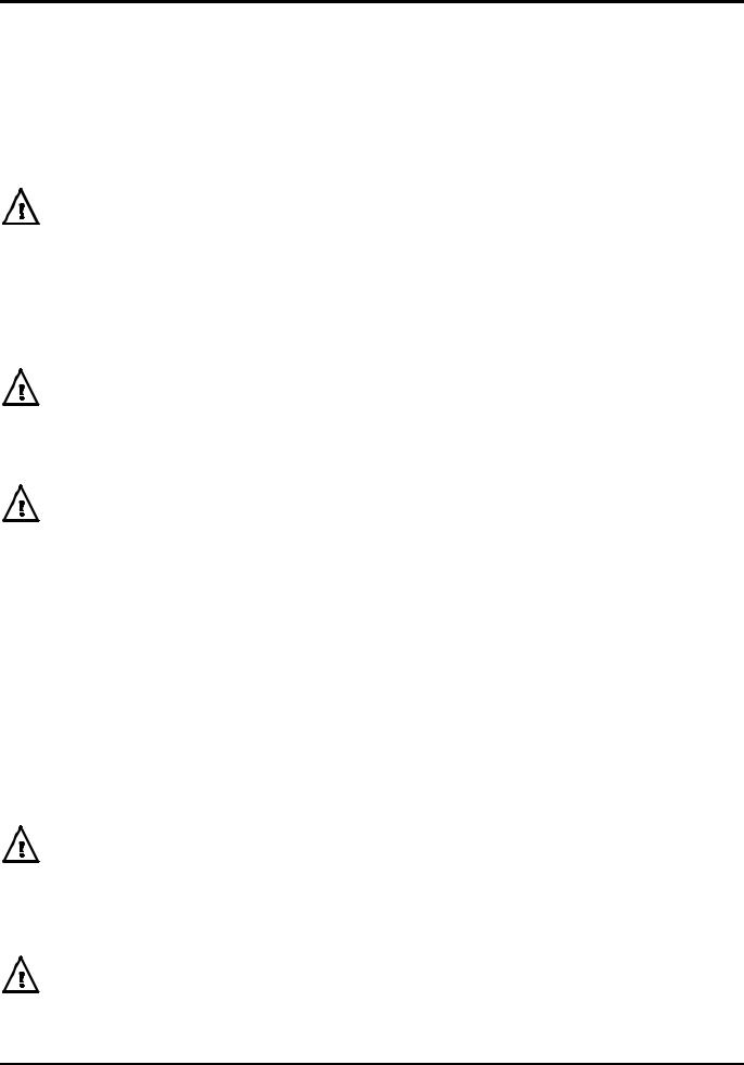
AUX OUT is a TTL/CMOS level output synchronous with MAIN OUT and with the same symmetry. However, the phase of the AUX OUT can be varied with respect to the MAIN OUT by changing the PHASE setting on the TRIGger edit menu.
Auxiliary Output Phase
Sine
Square
Triangle
Ramp
AUX 0º
AUX 90º
AUX 180º
0º 180º 360º
The convention adopted for phase in this instrument is illustrated in the diagram. 0° is always the first data point in waveform memory. On symmetrical waveforms 0° is the rising edge ‘zero-crossing’ point for sine, square, triangle and pulse waveforms; 0° is the start point of ramps, staircase and arbitrary waves. When the phase is set to 0° the rising edge of the AUX OUT squarewave is at 0° too. When the phase is set to a positive value, e.g. +90°, the AUX OUT squarewave follows MAIN OUT by 90°, when the phase is set to a negative value AUX OUT leads MAIN OUT.
The phase is set by pressing the blue EDIT key followed by TRIG to select the trigger edit menu; the edit cursor is then moved to the PHASE field using the FIELD keys. PHASE can be entered directly from the keyboard, using the +/- key to change the sign if necessary, or by rotary control.
Above 30kHz the AUX OUT accompanying sine, triangle, square and pulse waveforms is automatically switched such that it is derived from the comparator (driven by the DDS sinewave) used to generate higher frequency MAIN OUT squarewaves and pulses; see the DDS Principles section for further information. This ensures a jitter-free AUX OUT signal up to the maximum frequency of the generator but means that phase shifting between MAIN OUT and AUX OUT is not then possible. However, this constraint can be removed by changing the setting on the OPTions menu from AUX OUTPUT=AUTO to AUX OUTPUT=LOW FREQ; the AUX OUT signal then continues to be generated independently, with phase adjustable with respect to the MAIN output, although the 1 clock (36ns) jitter will become increasingly significant at higher frequencies. Changing AUTO settings is described more fully in the next section, Waveform Generator Options.
The AUX OUT signal accompanying ramp, staircase and arbitrary waveforms is, by default, always generated independently; phase shift is adjustable across the frequency range but again clock jitter becomes increasingly significant at higher frequencies.
Waveform Generation Options
A number of parameters are, by default, switched automatically either when the frequency is set above 30kHz or when the operating mode is changed such that the best overall performance is achieved across the whole generator frequency range; see the DDS Principles section for further details of the 30kHz changeover. In addition, triangle, ramp, staircase and arbitrary waveforms can be inhibited from being set above 100kHz, to ensure that they are not used accidentally at frequencies where the waveshape is noticeably deteriorating. In all cases, however the default choice can be overridden by the user by changing the setting on the OPTions menu.
22

SQWAVE GEN=AUTO
FILTER=AUTO
AUX=AUTO FSTOP=ON
SWEEP TGEN OUT=AUTO
The OPTions edit menu shown above is selected by pressing the blue EDIT key followed by OPTN (the shifted function of 1). The following descriptions, grouped together in this section for reference convenience, should be read in conjunction with the main explanations of the appropriate parameter elsewhere in this manual. Each parameter is altered by moving the edit cursor to the appropriate field with the FIELD keys and using the DIGIT keys or rotary control to change the setting.
Squarewave Generation
In LOW FREQency mode the squarewave and pulse waves are generated digitally; in this way precision squarewaves can be generated down to very low frequencies without the edge uncertainty that would be associated with conventional ramp-and-comparator techniques. Above approximately 27kHz (clock frequency, 27.487MHz, ÷1024) the waveforms are sampled and the 1 clock (36ns) uncertainty introduces edge jitter which becomes increasingly significant at higher frequencies. In HIGH FREQuency mode the squarewave and pulses are derived from the output of a comparator driven by the DDS generated sinewave. The sinewave is, by default, filtered and jitter-free; the high frequency squareware and pulse waveforms are thus jitter free too.
In AUTO mode (the default) the generation of squarewave and pulse waveforms is automatically switched from low to high frequency mode when the frequency exceeds 30kHz. However, when these waveforms are used in sweep and FSK modes, over a frequency range which includes the 30kHz changeover point, the generation mode will not change even though AUTO is selected.
Instead, the mode in use before sweep or FSK are turned on is maintained across the frequency range; this can of course be overridden by selecting either high or low frequency mode on the Options menu, as described above.
Filter
The generator contains a 7-stage elliptical filter which exhibits a sharp cut-off beyond the maximum generator frequency, reducing intermodulation spurii and clock harmonics to a very low level. With the default condition of FILTER=AUTO set on the Option menu, the filter is switched in automatically for sine, triangle, high frequency squarewave and high frequency pulse waveforms (although the squarewave and pulse waveforms themselves do not pass through the filter); the filter is automatically switched out for low frequency squarewave and pulses, ramp, staircase and arbitrary waveforms because of the degrading effect it has on fast transitions in the waveform. However, for all these waveforms the filter can be set to be always on (FILTER=ON) or always off (FILTER=OFF); this has the advantage that, for example, an arbitrary waveform with an essentially sinusoidal content can be output with the filter on.
When Noise is selected, see Special Waveforms section, this 7-stage filter is always off, whatever the FILTER = setting, and a simple 700kHz low pass RC filter is switched in instead.
Auxiliary Output
When sine, triangle, squarewave or pulse waveforms are selected and with AUX OUTPUT=AUTO the auxiliary output squarewave generation switches automatically at 30kHz from DDS generation to a signal derived from a comparator driven by the DDS sinewave; the advantages of this approach are the same as those detailed previously in the Squarewave Generation section. However, as detailed in the Auxiliary Output Phase section, the high frequency generation mode has the disadvantage that a phase difference can no longer be set between AUX OUT and MAIN OUT. The automatic switchover at 30kHz can therefore be overridden by setting AUX OUTPUT=LOW FREQuency, to maintain it in true DDS mode, or AUX OUTPUT=HIGH FREQuency to lock it in high frequency mode. With AUX OUTPUT=AUTO there is no automatic mode changeover if ramp, staircase or arbitrary waveforms are selected; high frequency mode can however be forced by setting AUX OUTPUT=HIGH FREQ.
23
Loading...