


 Loading...
THURLBY THANDAR INSTRUMENTS
Model 1906
COMPUTING MULTIMETER
INSTRUCTION MANUAL

|
Table of Contents |
Introduction |
1 |
Specification |
2 |
Safety |
5 |
EMC |
7 |
Installation |
8 |
Introduction to Front Panel |
9 |
Making Basic Measurements |
10 |
Advanced Features |
13 |
Error Messsages |
20 |
Default Instrument Settings |
20 |
Remote Operation |
21 |
Remote Commands |
29 |
Maintenance and Repair |
44 |
Introduction
This instrument is a mains operated, high performance autoranging multimeter providing 5½ digit resolution (± 210000 counts) switchable to 4½ digits (± 21000 counts) for a higher reading rate. It has a 7-segment l.e.d. display coupled with l.e.d. annunciators for displayed units and instrument status.
The main features are :-
•ARC serial interface as standard, GPIB optional
•True RMS AC measurements
•Four-terminal Ohms
•Selectable audible continuity checker
•T/Hold mode - holds onto a stable reading until updated
•Display nulling - a different value can be set up for each function
•100 point data logger - circular or linear store
•Measurement post-processing:-
percentage deviation from a user-entered reference decibel calculations
linear scaling with offset
limits comparison for go/no go testing
automatic storage of minimum and maximum readings
•Selectable digital filter
•Programmable buzzer
•Battery-backed RAM :-
storage of six instrument set-ups automatic power up with last used settings.
retention of user entered references and scaling factors retention of logged data
•Software calibration with constants stored in EEPROM
1

Specification
Accuracy
Accuracies apply for 1 year 18°C to 26°C. Temperature coefficient outside these limits is <0·1 x quoted range accuracy per °C. Warm-up time to rated accuracy is 1 hour.
DC Volts
Range |
Accuracy |
Input Impedance |
Max Input |
200mV |
0·017% + 3d |
10MΩ or >1GΩ |
|
2V |
0·012% + 3d |
|
1kV DC or AC |
20V |
0·019% + 3d |
|
Peak any range |
200V |
0·019% + 3d |
10MΩ |
|
1000V |
0·019% + 3d |
|
|
Resistance (Ohms)
Range |
Accuracy |
Max. Measuring Current |
Max. Input |
200 |
0·025% + 4d |
1·5mA |
|
2k |
0·019% + 3d |
1·5mA |
300V DC or RMS |
20k |
0·019% + 3d |
0·4mA |
continuous any |
200k |
0·019% + 3d |
40µA |
Ohms input any |
2M |
0·022% + 3d |
4µA |
range |
20M |
0·07% + 3d |
400nA |
|
Max open circuit voltage 3·5V.
Audible continuity check available on all ranges.
AC Volts (True RMS)
|
|
Accuracy |
|
|
Range |
45Hz - 5kHz |
5kHz - 10kHz |
10kHz-20kHz |
20kHz-50kHz |
200mV |
0·2% + 150d |
0·2% + 250d |
3% + 500d |
- |
2V |
0·2% + 150d |
0·2% + 250d |
0·5% + 300d |
3% + 1500D |
20V |
0·2% + 150d |
0·2% + 250d |
0·5% + 300d |
2% + 1000D |
200V |
0·2% + 150d |
0·2% + 250d |
0·5% + 500d |
- |
750V |
0·2% + 150d |
- |
- |
- |
Accuracy specifications apply for readings between 10% and 100% of full scale. Additional error at crest factor = 3 typically 0·7%.
Input impedance 1MΩ || <100 pF any range. Max input 750V rms, 1kV peak, any range.
DC Amps
Range |
Accuracy |
Voltage Burden |
Max Input |
200µA |
0·08% + 12d |
|
|
2mA |
0·08% + 12d |
300 mV max |
1A, 300V |
20mA |
0·08% + 12d |
|
fuse protected |
200mA |
0·08% + 12d |
|
|
10A, up to 2000mA |
0·08% + 12d |
650mV max |
10A, 300V |
10A, above 2000mA |
0·12% + 12d |
|
fuse protected |
2

AC AMPS (True RMS)
Range |
Accuracy |
Voltage Burden |
Max Input |
|
45 Hz - 1 kHz |
|
|
200µA |
0·37% + 100d |
|
|
2mA |
0·37% + 100d |
300mV max |
1A, 300V |
20mA |
0·37% + 100d |
|
fuse protected |
200mA |
0·37% + 100d |
|
|
10A, up to 2000mA |
0·37% + 100d |
650mV max |
10A, 300V |
10A, above 2000mA |
0·4% + 100d |
|
fuse protected |
Accuracy specifications apply for readings between 10% and 100% of full scale. Additional error at crest factor = 3 typically 0·7%.
Display
Display Type: |
|
13mm LED, 8 digit. |
|
Scale Length: |
|
Selectable 5½ digit or 4½ digit. |
|
Reading Rate: |
|
|
|
4½ |
digit: |
5 readings / sec |
All functions except Ohms |
|
|
1·4 readings / sec |
Ohms |
5½ |
digit: |
3·5 readings / sec |
DC and AC current |
|
|
3·5 readings / sec |
AC volts |
|
|
3 readings / sec |
DC volts |
|
|
1 reading / sec |
Ohms |
Overrange Indication: |
Displays OL if input too great for range. |
||
Overflow Indication: |
|
Displays OFLO if calculated result too large for display. |
|
Annunciators: |
|
L.e.d. annunciators for range, function and program modes. |
|
Input Characteristics
Input Current: |
< 100 pA. |
DC NMR: |
> 60dB at 50/60Hz. |
1k Unbalanced CMR: |
> 120dB at DC/50Hz/60Hz, DC ranges; |
|
> 60dB at DC/50Hz/60Hz, AC ranges. |
Hi Z: |
Switchable high impedance (>1GΩ) on 200mV and 2V DC ranges. |
Computing Functions |
|
Null: |
Operates over full range; values can be stored for every function. |
Digital Filter: |
10 options, including optimised default values for each range and |
|
function. |
T/HOLD (Touch & Hold): Reading is held when stable. |
|
% DEV: |
Displays % deviation from entered reference value. |
dB: |
Displays measurement in dB relative to 1V, 1mA, 1kΩ or user entered |
|
value, or in dBm. |
Ax+B: |
Linear scaling of results, with offset. |
Limits: |
Reading displayed with H, L, or P (pass) with respect to user-defined |
|
high and low limits. |
Min/Max: |
Minimum and maximum reading stored. |
Data Logger: |
Manual or automatic storage of 100 measurements. |
|
|
|
3 |

Interfaces
RS232: |
Baud rates 300, 1200 or 9600. Complies fully with the ARC (Addressable |
|
RS232 Chain) interface standard. Address selectable from the front panel. |
GPIB (Optional): |
Fully complies with IEEE-488.2 |
Power Requirements |
|
AC Input: |
220V-240V or 110V-120V AC ±10%, 50/60Hz by rear panel adjustment. |
|
Installation Cagetory II. |
Power Consumption: |
25VA max. |
General |
|
Operating Range: |
+5°C to +40°C, 20% to 80% RH |
Storage Range: |
–40°C to +60°C |
Environmental: |
Indoor use at altitudes up to 2000m, Pollution Degree 1. |
Size: |
260(W) x 88(H) x 235(D)mm, excluding handle and feet |
Weight: |
2·2kg. |
Safety: |
Complies with EN61010-1 |
EMC: |
Complies with EN61326 |
4
Safety
This instrument is a Safety Class 1 according IEC classification and has been designed to meet the requirements of EN61010-1 (Safety Requirements for Electronic Equipment for Measurement, Control and Laboratory Use). It is an Installation Category II instrument intended for operation from a normal single phase supply.
This instrument has been tested in accordance with EN61010-1 and has been supplied in a safe condition. This instruction manual contains some information and warnings which have to be followed by the user to ensure safe operation and to retain the instrument in a safe condition.
This instrument has been designed for indoor use in a Pollution Degree 1 environment (no pollution, or only dry non-conductive pollution) in the temperature range 5°C to 40°C,
20% - 80% RH (non-condensing). It may occasionally be subjected to temperatures between +5°C and −10°C without degradation of its safety. It has been designed for Installation Category I measurement use to 1000 V and Installation Category lI measurement use to 600V. The full definitions of Categories I and II can be found in IEC664, but the following can be taken as a guide:
Installation Category I is signal level e.g. telecommunication, electronic equipment, with smaller transient overvoltages than Installation Category II.
Installation Category II is local domestic supply level, e.g portable equipment and appliances. In particular, Category II does not include distribution level supplies e.g. three phase installations which are classified as Installation Category III.
Use of this instrument in a manner not specified by these instructions may impair the safety protection provided. Do not operate the instrument outside its rated supply voltages or environmental range. In particular excessive moisture may impair safety.
WARNING! THIS METER MUST BE EARTHED
Any interruption of the mains earth conductor inside or outside the instrument will make the instrument dangerous. Intentional interruption is prohibited. The protective action must not be negated by the use of an extension cord without a protective conductor. The mains plug must be inserted before connections are made to circuits being measured.
When the instrument is connected to its supply or its inputs are connected to live voltages, terminals may be live and opening the covers or removal of parts (except those to which access can be gained by hand) is likely to expose live parts. The apparatus shall be disconnected from all voltage sources before it is opened for any adjustment, replacement, maintenance or repair.
Any adjustment, maintenance and repair of the opened instrument under voltage shall be avoided as far as possible and, if inevitable, shall be carried out only by a skilled person who is aware of the hazard involved. If the instrument is clearly defective, has been subject to mechanical damage, excessive moisture or chemical corrosion the safety protection may be impaired and the apparatus should be withdrawn from use and returned for checking and repair.
Make sure that only fuses with the required rated current and of the specified type are used for replacement. The use of makeshift fuses and the short-circuiting of fuse holders is prohibited. Do not wet the instrument when cleaning it.
The following symbols are used on the multimeter and in this manual:-
WARNING - risk of electric shock |
|
|
|
|
|
direct current |
|
|
|
||||
|
|
|
||||
CAUTION - refer to accompanying documentation; |
|
|
|
|
|
alternating current |
incorrect operation may damage the meter |
|
|
|
|
|
|
mains earth (ground) |
|
|
|
|
|
|
|
|
|||||
|
5 |
|||||

EC Declaration of Conformity
We Thurlby Thandar Instruments Ltd
Glebe Road
Huntingdon
Cambridgeshire PE29 7DR
England
declare that the
Model 1906 Computing Multimeter and Model 1906GP Computing Multimeter with GPIB
meets the intent of the EMC Directive 2004/108/EC and the Low Voltage Directive 2006/95/EC. Compliance was demonstrated by conformance to the following specifications which have been listed in the Official Journal of the European Communities.
EMC |
|
|
|
|
Emissions: |
a) |
EN61326-1 |
(2006) |
Radiated, Class B |
|
b) |
EN61326-1 |
(2006) |
Conducted, Class B |
|
c) |
EN61326-1 |
(2006) |
Harmonics, referring to EN61000-3-2 (2006) |
Immunity: |
EN61326-1 (2006) Immunity Table 1, referring to: |
||
|
a) |
EN61000-4-2 (1995) Electrostatic Discharge |
|
|
b) |
EN61000-4-3 (2006) |
Electromagnetic Field |
|
c) |
EN61000-4-11 (2004) Voltage Interrupt |
|
|
d) |
EN61000-4-4 (2004) |
Fast Transient |
|
e) |
EN61000-4-5 (2006) |
Surge |
|
f) |
EN61000-4-6 (2007) |
Conducted RF |
Performance levels achieved are detailed in the user manual.
Safety
Multimeter: EN61010-1
Installation Category I measurements to 1000V, Installation Category II measurements to 600V, Pollution Degree 1.
Probes: IEC1010-2-031
Rated to 1000V, Installation Category III.
CHRIS WILDING TECHNICAL DIRECTOR
1 May 2009
6

EMC
This instrument has been designed to meet the requirements of the EMC Directive 2004/108/EC. Compliance was demonstrated by meeting the test limits of the following standards:
Emissions
EN61326-1 (2006) EMC product standard for Electrical Equipment for Measurement, Control and Laboratory Use. Test limits used were:
a)Radiated: Class B
b)Conducted: Class B
c)Harmonics: EN61000-3-2 (2006) Class A; the instrument is Class A by product category.
Immunity
EN61326-1 (2006) EMC product standard for Electrical Equipment for Measurement, Control and Laboratory Use.
Test methods, limits and performance achieved are shown below (requirement shown in brackets):
a)EN61000-4-2 (1995) Electrostatic Discharge : 4kV air, 4kV contact, Performance B (B).
b)EN61000-4-3 (2006) Electromagnetic Field:
3V/m, 80% AM at 1kHz, 80MHz – 1GHz: Performance B† (A) and 1.4GHz to 2GHz: Performance A (A); 1V/m, 2.0GHz to 2.7GHz: Performance A (A).
c)EN61000-4-11 (2004) Voltage Interrupt: ½ cycle and 1 cycle, 0%: Performance A (B); 25 cycles, 70% and 250 cycles, 0%: Performance B (C).
d)EN61000-4-4 (2004) Fast Transient, 1kV peak (AC line), 0·5kV peak (signal connections), Performance B (B).
e)EN61000-4-5 (2006) Surge, 0·5kV (line to line), 1kV (line to ground), Performance A (B).
f)EN61000-4-6 (2007) Conducted RF, 3V, 80% AM at 1kHz (AC line only; signal connections <3m, therefore not tested), Performance B† (A).
According to EN61326-1 the definitions of performance criteria are:
Performance criterion A: ‘During test normal performance within the specification limits.’
Performance criterion B: ‘During test, temporary degradation, or loss of function or performance which is self-recovering’.
Performance criterion C: ‘During test, temporary degradation, or loss of function or performance which requires operator intervention or system reset occurs.’
† Note: The 1906 is a sensitive measuring instrument and, if subjected to sufficiently large RF fields (radiated or conducted), measurements may deviate beyond the accuracy specification at certain frequencies up to 800MHz. However, possible deviations will be small and infrequent and are not deemed to be a problem in practice. In all other respects the instrument will operate normally (Performance A) in fields up to 3V/m.
Cautions
To ensure continued compliance with the EMC directive observe the following precautions:
a)Only use screened cables and connectors to connect between the multimeter's RS232/GPIB interfaces and other equipment.
b)After opening the case for any reason ensure that all signal and ground connections are remade correctly and that case screws are correctly refitted and tightened.
c)In the event of part replacement becoming necessary, only use components of an identical type, see the Service Manual.
7

Installation
Mains Operating Voltage
Check that the instrument is set up for the required operating voltage. The operating voltage is set by the orientation of the fuse drawer located immediately under the mains socket. The selected operating voltage is shown by the printing which is at the top of the fuse drawer (when the instrument is the right way up). The fuse drawer can be rotated by first withdrawing it from the mains socket housing with the power plug removed and then reinserting it.
Ensure that the correct mains fuse is fitted for the operating voltage selected. The correct mains fuse types are:
for 230V operation - 125mA (T) 250V for 115V operation - 250mA (T) 250V
Mains Lead
When a three core mains lead with bare ends is provided it should be connected as follows:-
BROWN |
- |
MAINS LIVE |
BLUE |
- |
MAINS NEUTRAL |
GREEN/YELLOW |
- |
MAINS EARTH |
WARNING! THIS METER MUST BE EARTHED
Any interruption of the mains earth conductor inside or outside the instrument will make the instrument dangerous. Intentional interruption is prohibited. The protective action must not be negated by the use of an extension cord without a protective conductor. The mains plug must be inserted before connections are made to circuits being measured.
Power On
The power switch is located bottom left of the front panel. At power up the meter displays the installed software revision whilst performing self-tests on the internal RAM and the EEPROM containing the calibration constants. At the end of these tests the meter will commence normal operation with all parameters set as they were at last switch off. If the self-test fails, the buzzer sounds and one of two error messages Error 1 or Error 2 will be displayed, see the Error Message section.
8

Introduction to Front Panel
The main display consists of eight 7-segment characters with decimal points which are used to give up to six digits of numerical information plus polarity indication. Displayed units are indicated by the top three l.e.d.s to the right of the digits (except when making dB or ∆% readings). The main display also gives prompts, error messages and instrument status.
Below the displayed units l.e.d.s is the CONTINUITY indicator which lights when the audible continuity tester is active.
To the left of the main display at the top is the recessed CAL enable switch with its indicator which lights when the meter is in its calibration mode.
Below the CAL l.e.d. are three computation indicators which light to show which computations are active.
The keyboard consists of momentary switches each with more than one function. Colour coding shows common levels of key function. Primary level functions are indicated above the keys in black and are accessed by a single key stroke. Secondary level functions are shown below the keys in blue and are accessed by first pressing the PROG key. Tertiary level functions are shown in red; these are mostly for entering numerical data and for examining logged data.
Above most of the keys are l.e.d.s which indicate that the primary key function has been selected.
Manual range selection and auto/manual ranging are primary functions of the three keys grouped on the right hand side of the keyboard. All basic meter functions are selected as primary functions of the six keys to left of the range keys. Remote control functions are grouped bottom left of the keyboard.
The six input sockets are colour coded, black sockets being considered less positive compared to red and white. The black socket marked V/Ω/A serves as the common terminal for all measurements and is connected to analogue common.
Fig. 1 - Front Panel Layout
9
Making Basic Measurements
General
If basic measurements are required, with no post-processing of the results, all programs currently operating can be cancelled by pressing PROG followed by CANCEL. Note that the l.e.d. above the PROG key lights to show that the next key press will invoke the function specified under that key in blue.
Scale Length
The scale length may be ± 210000 (5½ digits) for high accuracy or ± 21000 (4½ digits) if the higher measurement rate is required. The selection is made by pressing the PROG key twice.
Function Selection
Voltage, current and resistance measurement functions are selected by pressing the appropriate V, mA, 10A or Ω key. For voltage and current measurements ac or dc is selected by pressing either the AC or DC key. The l.e.d.s above these switches indicate the currently selected function.
Note that when some post-processing programs are running function changes are inhibited; this is indicated by In Pro being displayed. All programs can be cancelled simultaneously by
pressing PROG followed by CANCEL or programs can be selectively cancelled (refer to the appropriate section in ADVANCED FEATURES).
When V DC is selected a high input impedance of >1GΩ (HI Z) is available on the 200mV and 2V ranges. Successive presses of the V key toggle HI Z on and off when the meter switched to either the 200mV or 2V DC ranges. The HI Z l.e.d. indicates when the input is actually high impedance. If HI Z has been selected the l.e.d. will turn off automatically when the meter is switched to 20V and above and on again when the meter is in the 200mV or 2V ranges.
Range Selection
If the signal input to the meter is too big for the range then OL is displayed and a higher range must be selected if there is one. This may be done automatically or manually.
Autoranging mode is selected by pressing the AUTO key. When in autorange mode the l.e.d. above the AUTO key is lit and the meter will automatically select a range where the reading is between full scale and 5% of full scale.
Successive presses of the AUTO key toggle autoranging on and off.
Meter ranges are selected manually by pressing either the RANGE ▲ key or the RANGE ▼ key. If the meter is in autorange then pressing either of these keys selects manual ranging, deselects autoranging and the AUTO l.e.d. is extinguished.
If the meter function is changed the range just prior to the change is stored. This allows the meter to switch automatically to the same range if the first function is again selected. This can save time when switching between different types of measurements.
Making Voltage Measurements
Voltage measurements are made using the red V/Ω and the black V/Ω/A sockets having selected the required voltage function as explained above. The V/Ω/A socket is connected to analogue common inside the meter and for DC measurements the red socket, which is also marked HI, is the positive input.
10
Making Current Measurements
Current measurements up to 200mA are made using the mA and V/Ω/A sockets; the mA socket is the positive input.
Current measurements up to 10A are made using the 10A and V/Ω/A sockets; the 10A socket is the positive input. The 10A range is treated as a separate function from the other current ranges and autoranging does not extend from the 200mA range to the 10A range.
Current Range Protection
The mA input socket is protected by a fuse which is mounted on the instrument's rear panel. This provides protection for the 200µA, 2mA, 20mA and 200mA ranges.
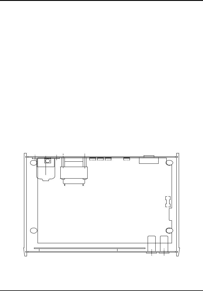
The 10A input is protected by a fuse mounted inside the instrument on the main PCB (see Fig. 2). To replace this fuse the top cover must be removed:
1.Disconnect the instrument from all voltage sources.
2.Unclip the front bezel by gently pulling the centre of each long edge up and forward.
The case halves are held together by 4 plastic push-rivets. Use the blade of a small screwdriver in the slot beside each rivet to first ease out the rivet head and then fully remove the rivet body. Separate the case halves. Visit www.tti-test.com for further details.
3.Replace the fuse with one of an identical rating using the diagram below as a guide.
4.Reassemble in the reverse order.
The current range protection fuse ratings are:-
mA input |
(rear panel) |
- |
20mm, |
1A (F) HBC |
10A input |
(inside case) |
- |
20mm, |
10A (F) HBC |
Rear Panel
10 A range Protection fuse
Front Panel
Fig. 2 - Location of 10A Range Fuse
11
Making Resistance Measurements and Continuity Checks
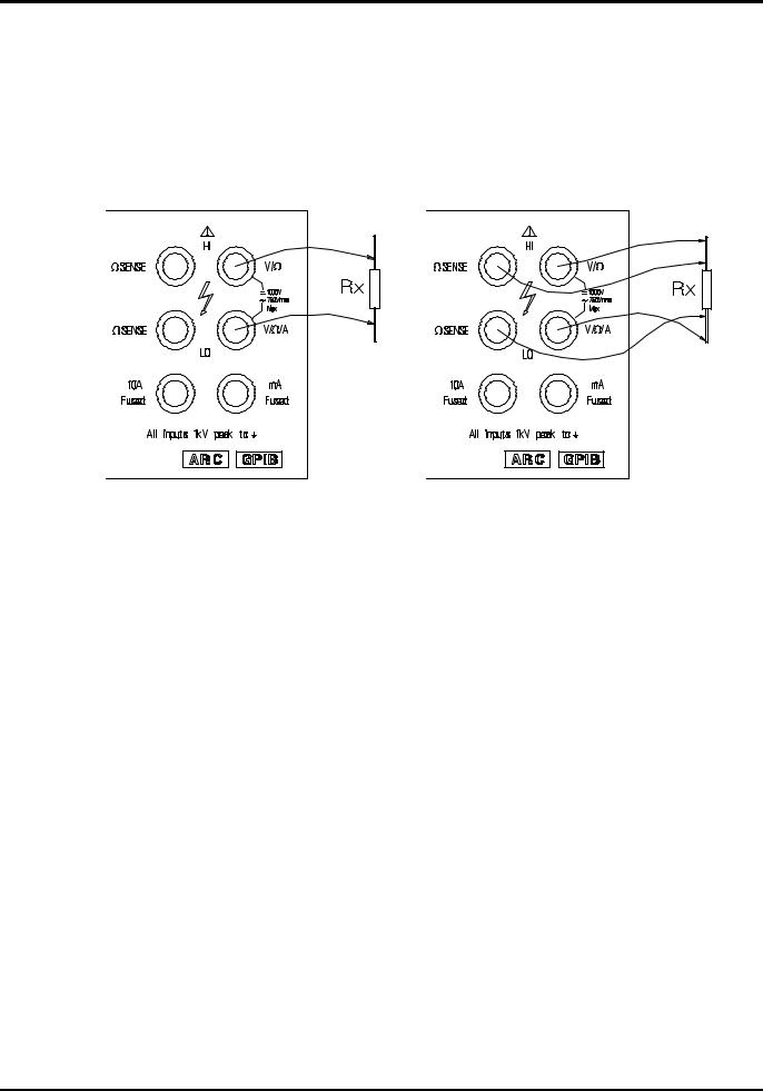
Resistance measurements may be made using either a two-terminal or a four-terminal method. The four-terminal method overcomes inaccuracies due to test lead resistance by sensing the voltage across the unknown resistance via the separate HI and LO Ω SENSE inputs. If the sense inputs are not connected externally the measurement becomes two-terminal, the voltage sensing being performed internally at the V/Ω and V/Ω /A inputs.
The connections for four and two terminal measurements are shown in Fig. 3. For correct fourterminal operation the proper lead polarity must be maintained.
2 Terminal |
4 Terminal |
Fig. 3 - Resistance Measurement Connections
The CONT l.e.d. is lit whenever the continuity checker is turned on and the buzzer will sound when a low resistance is sensed. The continuity checker is turned on or off via the BUZZER selections. To access these selections first press PROG followed by BUZZER. The display shows cont n if the continuity check is currently off or cont y if it is on. To toggle the continuity checker between off and on press any key with a number beside it. When the selection is made press ENTER to return to normal meter operation.
Note that having pressed PROG followed by BUZZER other buzzer selections are made available by repeated presses of the SCROLL key, see ADVANCED FEATURES section. Pressing ENTER saves all the buzzer selections made.
The continuity checker is available on all resistance ranges and senses when the voltage across the unknown is less than 50mV. This represents approximately 60Ω on both the 200Ω and 2kΩ ranges, more on higher ranges.
Making Diode Checks
Diode functionality checks can be made using the resistance ranges. The recommended range is the 2kΩ range where the measurement current is just under 1mA. Forward biased silicon junctions will produce an approximately mid-scale reading. This is achieved by connecting the anode to the red V/Ω socket and the cathode to the black V/Ω /A socket. With the reverse connections a good silicon junction will give an OL reading.
12

Advanced Features
Parameter Values
The advanced features include programs for post-processing readings to produce scaled, logged or compared results all of which require numerical parameters to be entered. Floating-point numbers are entered directly as individual digits at the flashing edit point using the red numeric keys. The position of the flashing edit point may be moved through the number by presses of the STEP EDIT key. The edit cursor wraps round from the least significant digit to the most significant digit.
The position of the decimal point may be changed using the SCROLL key. Where the numerical value has units, e.g. mV, the appropriate displayed units l.e.d. is lit and the SCROLL key moves the decimal point, in conjunction with the units l.e.d.s, through the permitted possibilities. For numbers with no units the decimal point is simply stepped right, wrapping round to the left when it reaches the right hand end. The sign can be toggled using the ± key.
Once the complete value has been set up on the display pressing ENTER stores the value and either the program commences operation or the next parameter is displayed for editing if more than one parameter is required. If CANCEL is pressed before the last parameter of a particular program is ENTERed then operation of that program is cancelled. Fixed decimal point numbers are entered directly at a flashing edit digit as for floating point numbers except that the SCROLL key has no effect on the decimal point position. Where the choice is limited to only a few entries the entry method is by scrolling through the possibilities using the RANGE ▲/ SCROLL and RANGE ▼/ STEP EDIT keys. Pressing ENTER when the required choice is displayed stores the value.
All parameter information is retained in battery-backed memory so that the next time the parameter is edited the value that first appears when a program is invoked will be the last used value. Separate values for the parameters used by ∆%, Ax+B and LIMITS are retained for each meter function.
Overflow Indication
The displayed result of measurement post-processing is allowed to have values up to 999999. If the result is greater than 999999 then OFLO is displayed. This differentiates between calculated overflows and hardware overload when the input signal is too large for the range and OL is displayed.
Function Cancellation
All programs can be cancelled simultaneously by pressing PROG followed by CANCEL. Individual programs can be cancelled by invoking the program and then pressing CANCEL before any parameter information is ENTERed e.g the key sequence PROG dB CANCEL will cancel the dB program. Note however that T/HOLD, which does not have any parameters, can only be cancelled by holding the key down for three seconds until CAnCEL'd is displayed.
Null
NULL is toggled on and off by successive presses of the NULL key. The NULL l.e.d. is lit when the NULL feature is in operation. Turning on NULL stores the currently displayed value which is then subtracted as a real value from all subsequent readings made in that meter function until NULL is cancelled. Because the null value is stored as a real value the same amount is subtracted from all reading regardless of range i.e. if 100mV is stored as the null value then 100mV will be subtracted from all measurements even if they are made in the 1kV range.
A separate null value can be stored for all basic meter functions plus one for nulling after dB calculations. The NULL l.e.d. indicates that a null value has been stored for a particular function and will switch on or off if the function is changed depending on whether a null value has been previously stored for the new function.
The null operation is performed on all measurements before any further post processing with one exception. If the NULL value is stored while the dB program is in progress then the null value is in dBs and is subtracted from the result of the dB calculations. If the null value is stored before invoking dB then the nulling is performed before the dB calculations are made.
13
Loading...