


 Loading...
TGA1230
30 MHz Synthesised Arbitrary
Waveform Generator
User Manual
Manual Copyright © 1997 T T Instruments Ltd. All rights reserved. Software Copyright © 1997 T T Instruments Ltd. All rights reserved. WaveCAD Copyright © 1997 Tabor Electronics. All rights reserved.
Book Part Number 48591 - 0510 Issue 4.

|
Contents |
|
Introduction |
3 |
|
Specifications |
4 |
|
Safety |
11 |
|
EMC |
12 |
|
Installation |
12 |
|
Connections |
14 |
|
Front Panel Connections |
14 |
|
Rear Panel Connections |
15 |
|
General |
17 |
|
Initial Operation |
17 |
|
Principles of Operation |
19 |
|
Standard Waveform Operation |
21 |
|
Setting Generator Parameters |
21 |
|
Warnings and Error Messages |
24 |
|
SYNC Output |
25 |
|
Sweep Operation |
26 |
|
General |
26 |
|
Setting Sweep Parameters |
27 |
|
Triggered Burst and Gate |
30 |
|
General |
30 |
|
Triggered Burst |
31 |
|
Gated Mode |
32 |
|
Sync Out in Triggered Burst and Gated Mode |
32 |
|
Tone Mode |
33 |
|
Other Modulation Modes |
35 |
|
External VCA |
35 |
|
External SUM In |
35 |
|
Amplitude Range for Each Attenuator Step |
36 |
|
Arbitrary Waveform Generation |
37 |
|
Introduction |
37 |
|
Creating New Waveforms |
38 |
|
Modifying Arbitrary Waveforms |
39 |
|
Arbitrary Waveform Sequence |
44 |
|
Frequency and Amplitude Control with Arbitrary Waveforms |
45 |
|
Sync Out Settings with Arbitrary Waveforms |
46 |
|
Waveform Hold in Arbitrary Mode |
47 |
|
|
|
|
|
1 |
|

Output Filter Setting |
47 |
WaveCAD Arbitrary Waveform Creation Software |
48 |
Pulse and Pulse-trains |
50 |
Pulse Set-up |
50 |
Pulse-train Setup |
51 |
Waveform Hold in Pulse and Pulse-Train Modes |
53 |
Synchronising Generators |
54 |
System Operations from the Utility Menu |
56 |
Calibration |
59 |
Equipment Required |
59 |
Calibration Procedure |
59 |
Calibration Routine |
60 |
Remote Calibration |
61 |
Remote Operation |
62 |
Address and Baud Rate Selection |
62 |
Remote/Local Operation |
62 |
ARC Interface |
63 |
GPIB Interface |
65 |
Power on Settings |
67 |
Status Reporting |
67 |
ARC Remote Command Formats |
70 |
GPIB Remote Command Formats |
70 |
Remote Commands |
72 |
Frequency and Period |
72 |
Amplitude and DC Offset |
72 |
Waveform Selection and Definition |
73 |
Waveform Sequence Control |
74 |
Arbitrary Waveform Editing |
75 |
Mode Commands |
76 |
Input/Output control |
76 |
Status Commands |
77 |
Miscellaneous Commands |
78 |
Remote Command Summary |
79 |
Maintenance |
82 |
Appendix 1. Warning and Error Messages |
83 |
Appendix 2. SYNC OUT Automatic Settings |
86 |
Appendix 3. Factory System Defaults |
87 |
2

Introduction
This Synthesised Programmable Arbitrary Waveform Generator uses a combination of direct digital synthesis and phase lock loop techniques to provide high performance and extensive facilities in a compact instrument. It can generate a wide variety of waveforms between 0·1mHz and 15MHz with high resolution and accuracy.
Arbitrary waveforms may be defined with 12 bit vertical resolution and from 4 to 65536 horizontal points. In addition a number of standard waveforms are available including sine, square, triangle, ramp and pulse.
Arbitrary waveforms may be replayed at a user specified waveform frequency or period, or the sample rate may be defined in terms of period or frequency.
Extensive waveform editing features between defined start and end points are incorporated, including waveform insert, point edit, line draw, amplitude adjust and invert. More comprehensive features are available using the WaveCAD arbitrary waveform creation software supplied. WaveCAD is a powerful Windows-based design tool that enables the user to create waveforms from mathematical expressions, from combinations of other waveforms, freehand, or using a combination of all three techniques. Waveforms created in this way are downloaded via the RS232 or optional GPIB interface.
Up to 50 waveforms may be stored with the length and name specified by the user. Waveforms may be strung together to form a sequence of up to four steps. Each waveform may have a user defined repeat count from 1 to 32768.
All waveforms can be swept over their full frequency range at a rate variable between 30 milliseconds and 15 minutes. Sweep can be linear or logarithmic, single or continuous. Single sweeps can be triggered from the front panel, the trigger input, or the digital interfaces. A sweep marker is provided.
Amplitude Modulation is available for all waveforms and is controlled from an external generator via the Ext VCA input.
All waveforms are available as a Triggered Burst whereby each active edge of the trigger signal will produce one burst of the carrier. The number of cycles in the burst can be set between 1 and 1048575. The Gated mode turns the output signal On when the gating signal is true and Off when it is false. Both Triggered and Gated modes can be operated from the internal Trigger Generator (0.005Hz to 50kHz), from an external source (dc to 1MHz) or by a key press or remote command.
The signals from the REF IN/OUT socket and the SYNC OUT socket can be used to phase lock two or more generators. This can be used to generate multi-phase waveforms or locked waveforms of different frequencies.
The generator parameters are clearly displayed on a backlit LCD with 4 rows of 20 characters. Soft-keys and sub menus are used to guide the user through even the most complex functions.
All parameters can be entered directly from the numeric keypad. Alternatively most parameters can be incremented or decremented using the rotary control. This system combines quick and easy numeric data entry with quasi-analogue adjustment when required.
The generator has an RS-232 interface as standard which can be used for remote control of all of the instrument functions or for the down-loading of arbitrary waveforms.
As well as operating as a conventional RS-232 interface, it can also be used in addressable mode whereby up to 32 instruments can be linked to one PC serial port as part of a TTi "ARC" system. Alternatively, a GPIB interface conforming to IEEE-488.2 is available as an option.
3

Specifications
Specifications apply at 18-28ºC after one hour warm-up, at maximum output into 50Ω
WAVEFORMS
Standard Waveforms
Sine, square, triangle, DC, positive ramp, negative ramp, sin(x)/x, pulse, pulse train, cosine, haversine and havercosine.
Sine, Cosine, Haversine, Havercosine
Range: |
0·1 mHz to 10 MHz. |
Resolution: |
0·1mHz (7 digits). |
Accuracy: |
10 ppm for 1 year. |
Temperature Stability: |
Typically <1 ppm/ºC. |
Output Level: |
5mV to 20V pk-pk from 50Ω. |
Harmonic Distortion: |
<0.1% THD to 100kHz; <–65dBc to 20kHz, |
|
<–50dBc to 1MHz, <–35dBc to 10MHz. |
Non-harmonic Spurii: |
<–65dBc to 1MHz, <–65dBc + 6dB/octave 1MHz to 10MHz. |
Square
Range: |
1 mHz to 15MHz. |
Resolution: |
1mHz (4 digits) |
Accuracy: |
± 1 digit of setting. |
Output Level: |
5mV to 20V pk-pk from 50Ω. |
Rise and Fall Times: |
<25ns |
Triangle
Range: |
0.1 mHz to 100kHz. |
Resolution: |
0.1mHz (7 digits) |
Accuracy: |
10 ppm for 1 year. |
Output Level: |
5mV to 20V pk-pk from 50Ω. |
Linearity Error: |
<0.1% to 30 kHz |
Ramps and Sin(x)/x
Range: |
0.1 mHz to 100kHz. |
Resolution: |
0.1mHz (7 digits) |
Accuracy: |
10 ppm for 1 year. |
Output Level: |
5mV to 20V pk-pk from 50Ω. |
Linearity Error: |
<0.1% to 30 kHz |
Pulse and Pulse Train
Output Level: |
5mV to 20V pk-pk from 50Ω. |
Rise and Fall Times: |
<25ns |
4

Period: |
|
Range: |
133·3ns to 100s. |
Resolution: |
4-digit. |
Accuracy: |
±1 digit of setting. |
Delay: |
|
Range: |
-99·9s to + 99·99s |
Resolution: |
0·002% of period or 33·33ns, whichever is greater. |
Width: |
|
Range: |
33·3ns to 99·99s |
Resolution: |
0·002% of period or 33·33ns, whichever is greater. |
Note that the pulse width and absolute value of the delay may not exceed the pulse period at any time.
Pulse trains of up to 10 pulses may be specified, each pulse having independently defined width, delay and level. The baseline voltage is separately defined and the sequence repetition rate is set by the pulse train period.
Arbitrary
Up to 50 user defined waveforms may be stored in RAM. Waveforms can be defined by front panel editing controls or by downloading of waveform data via RS232 or GPIB.
Waveform Memory Size: |
64k points. Maximum waveform size is 64k points, minimum |
|
waveform size is 4 points. |
Vertical Resolution: |
12 bits |
Sample Clock Range: |
100mHz to 30MHz |
Resolution: |
4 digits |
Accuracy: |
± 1 digit of setting. |
Sequence
Up to 4 waveforms may be linked. Each waveform can have a loop count of up to 32768. A sequence of waveforms can be looped up to 1048575 times or run continuously.
Output Filter
Selectable between 10MHz Elliptic, 10MHz Bessel or none.
MODULATION MODES
Triggered Burst
Each active edge of the trigger signal will produce one burst of the waveform, starting and stopping at the waveform position specified by the sync marker setting.
Carrier Waveforms: |
All standard and arbitrary |
Number of Cycles: |
1 to 1048575 |
Trigger Repetition Rate: |
dc to 50 kHz internal, dc to 1MHz external. |
Source: |
Internal from keyboard or trigger generator. |
|
External from TRIG IN or remote interface. |
5

Gated
Waveform will run while the Gate signal is true and stop while false.
Carrier Waveforms: |
All standard and arbitrary. |
Trigger Repetition Rate: |
dc to 50 kHz internal, dc to 1 MHz external. |
Gate Signal Source: |
Internal from keyboard or trigger generator. |
|
External from TRIG IN or remote interface. |
Sweep
Capability provided for both standard and arbitrary waveforms. Arbitrary waveforms are expanded or condensed to exactly 4096 points and DDS techniques are used to perform the sweep.
Carrier Waveforms: |
All standard and arbitrary except pulse, pulse train and sequence. |
Sweep Mode: |
Linear or logarithmic, up or down, triggered or continuous. |
Sweep Range: |
From 1mHz to 10 MHz in one range. Phase continuous. |
|
Independent setting of the start and stop frequency. |
Sweep Time: |
30ms to 999s (3 digit resolution). |
Marker: |
Variable during sweep. |
Sweep Trigger Source: |
The sweep may be free run or triggered from the following sources: |
|
Manually from keyboard. Externally from TRIG IN input or remote |
|
interface. |
Sweep Hold: |
Sweep can be held and restarted by the HOLD key. |
Tone
Capability provided for both standard and arbitrary waveforms. Arbitrary waveforms are expanded or condensed to exactly 4096 points and DDS techniques are used to allow instantaneous frequency switching.
Carrier Waveforms: |
All waveforms except pulse, pulse train and sequence. |
Frequency List: |
Up to 16 frequencies from 1mHz to 10MHz. |
Switching Sources: |
External trigger input. A true level will output the tone, a false level |
|
will stop the tone and switch to the next frequency on the list ready |
|
for the next true level. |
Min. switch time: |
20ms per tone. |
Using 2 instruments with their outputs summed together it is possible to generate DTMF test signals.
External Amplitude Modulation
Carrier frequency: |
Entire range for selected waveform. |
Carrier waveforms: |
All standard and arbitrary waveforms |
Modulation source: |
VCA/SUM IN socket. |
Frequency Range: |
DC - 100 kHz. |
Signal Range: |
Approximately 2·5V pk-pk for 100% level change at maximum |
|
output. |
6

External Signal Summing
Carrier frequency: |
Entire range for selected waveform. |
Carrier waveforms: |
All standard and arbitrary waveforms. |
Sum source: |
VCA/SUM IN socket. |
Frequency Range: |
DC to 10MHz. |
Signal Range: |
Approximately 5Vpk-pk input for 20Vpk-pk output. |
Trigger Generator
Internal source 0.005 Hz to 50kHz squarewave adjustable in 20us steps. 3 digit resolution. Available for external use from the SYNC OUT socket.
OUTPUTS
Main Output
Output Impedance:
Amplitude:
50Ω
5mV to 20V pk-pk open circuit (2.5mV to 10V pk-pk into 50Ω). Amplitude can be specified open circuit (hi Z) or into an assumed load of 50Ω or 600Ω in Vpk-pk, Vrms or dBm.
Amplitude Accuracy: |
2% ±1mV at 1kHz into 50Ω. |
Amplitude Flatness: |
±0.2dB to 200 kHz; ±1dB to 5 MHz; ±2dB to 10 MHz. |
DC Offset Range: |
±10V. DC offset plus signal peak limited to ±10V from 50Ω. |
DC Offset Accuracy: |
Typically 3% ±10mV, unattenuated. |
Resolution: |
3 digits for both Amplitude and DC Offset. |
Sync Out
Multifunction output user definable or automatically selected to be any of the following:
Waveform Sync: |
A square wave with 50% duty cycle at the main waveform |
(all waveforms) |
frequency, or a pulse coincident with the first few points of an |
|
arbitrary waveform. |
Position Markers: |
Any point(s) on the waveform may have associated marker bit(s) |
(Arbitrary only) |
set high or low. |
Burst Done: |
Produces a pulse coincident with the last cycle of a burst. |
Sequence Sync: |
Produces a pulse coincident with the end of a waveform |
|
sequence. |
Trigger: |
Selects the current trigger signal. Useful for synchronising burst |
|
or gated signals. |
Sweep Sync: |
Outputs a pulse at the start of sweep to synchronise an |
|
oscilloscope or recorder. |
Phase Lock Out: |
Used to phase lock two or more generators. Produces a positive |
|
edge at the 0° phase point. |
Output Signal Level: |
TTL/CMOS logic levels from typically 50Ω. |
7

Cursor/Marker Out
Adjustable output pulse for use as a marker in sweep mode or as a cursor in arbitrary waveform editing mode. Can be used to modulate the Z-axis of an oscilloscope or be displayed on a second ‘scope channel.
Output Signal Level: |
Adjustable from nominally 2V to 14V, normal or inverted; adjustable |
|
width as a cursor. |
Output Impedance: |
600Ω typical |
INPUTS |
|
Trig In |
|
Frequency Range: |
DC - 1MHz. |
Signal Range: |
Threshold nominally TTL level; maximum input ±10V. |
Minimum Pulse Width: |
50ns, for Trigger and Gate modes; 50us for Sweep mode; 20ms for |
|
Tone mode. |
Input Impedance: |
10kΩ |
VCA In |
|
Frequency Range: |
DC - 100kHz. |
Signal Range: |
2.5V for 100% level change at maximum output. |
Input Impedance: |
Typically 6kΩ. |
Sum In |
|
Frequency Range: |
DC - 10MHz. |
Signal Range: |
Approximately 5Vpk-pk input for 20Vpk-pk output. |
Input Impedance: |
Typically 1k2Ω. |
Hold
Holds an arbitrary waveform at its current position. A TTL low level or switch closure causes the waveform to stop at the current position and wait until a TTL high level or switch opening which allows the waveform to continue. The front panel HOLD key or remote command may also be used to control the Hold function. While held a rising edge at TRIG IN will return the waveform to the start. The front panel MAN/SYNC key or remote command may also be used to return the waveform to the start.
Input Impedance: |
10kΩ |
Ref Clock In/Out
Set to Input: |
Input for an external 10MHz reference clock. TTL/CMOS threshold |
|
level. |
Set to Output: |
Buffered version of the internal 10MHz clock. Output levels |
|
nominally 1V and 4V from 50Ω. |
Set to Phase Lock: |
Used together with SYNC OUT on a master and the TRIG IN on a |
|
slave to synchronise (phase lock) multiple instruments. |
8

INTERFACES
Full remote control facilities are available through the RS232 (standard) or optional GPIB interfaces.
RS232: |
Variable Baud rate, 9600 Baud maximum. 9-pin D-connector. |
|
Fully compatible with Thurlby-Thandar ARC (Addressable |
|
RS232 Chain) system. |
IEEE-488: |
Conforming with IEEE488.1 and IEEE488.2 |
GENERAL
Display: |
20 character x 4 row alphanumeric LCD. |
Data Entry: |
Keyboard selection of mode, waveform etc.; value entry direct |
|
by numeric keys or by rotary control. |
Stored Settings: |
Up to 9 complete instrument set-ups may be stored and |
|
recalled from battery-backed memory. Up to 50 arbitrary |
|
waveforms can also be stored independent of the instrument |
|
settings. |
Size: |
3U (130mm) height; half-rack (212mm) width; 330mm long. |
Weight: |
4.1kg. (9lb.) |
Power: |
100V, 110V-120V or 220V-240V AC ±10%, 50/60Hz, |
|
adjustable internally; 40VA max. Installation Category II. |
Operating Range: |
+5°C to 40°C, 20-80% RH. |
Storage Range: |
-20°C to + 60°C. |
Environmental: |
Indoor use at altitudes up to 2000m, Pollution Degree 2. |
Options: |
IEEE-488 interface; 19 inch rack mounting kit. |
Safety: |
Complies with EN61010-1. |
EMC: |
Complies with EN61326. |
9
EC Declaration of Conformity
We Thurlby Thandar Instruments Ltd
Glebe Road
Huntingdon
Cambridgeshire PE29 7DR
England
declare that the
TGA1230 30MHz Synthesised Arbitrary Waveform Generator with GPIB
meets the intent of the EMC Directive 89/336/EEC and the Low Voltage Directive 73/23/EEC. Compliance was demonstrated by conformance to the following specifications which have been listed in the Official Journal of the European Communities.
EMC |
|
|
|
|
Emissions: |
a) |
EN61326 (1998) |
Radiated, Class B |
|
|
b) |
EN61326 (1998) |
Conducted, Class B |
|
|
c) |
EN61326 (1998) |
Harmonics, referring to EN61000-3-2 (2000) |
|
Immunity: |
EN61326 (1998) Immunity Table 1, Performance B, referring to: |
|||
|
a) |
EN61000-4-2 (1995) Electrostatic Discharge |
||
|
b) |
EN61000-4-3 (1997) |
Electromagnetic Field |
|
|
c) |
EN61000-4-11 (1994) Voltage Interrupt |
||
|
d) |
EN61000-4-4 (1995) |
Fast Transient |
|
|
e) |
EN61000-4-5 (1995) |
Surge |
|
|
f) |
EN61000-4-6 (1996) |
Conducted RF |
|
Safety
EN61010-1 (1993) Installation Category II, Pollution Degree 2.
CHRIS WILDING TECHNICAL DIRECTOR
2 July 2001
10

Safety
This generator is a Safety Class I instrument according to IEC classification and has been designed to meet the requirements of EN61010-1 (Safety Requirements for Electrical Equipment for Measurement, Control and Laboratory Use). It is an Installation Category II instrument intended for operation from a normal single phase supply.
This instrument has been tested in accordance with EN61010-1 and has been supplied in a safe condition. This instruction manual contains some information and warnings which have to be followed by the user to ensure safe operation and to retain the instrument in a safe condition.
This instrument has been designed for indoor use in a Pollution Degree 2 environment in the temperature range 5°C to 40°C, 20% - 80% RH (non-condensing). It may occasionally be subjected to temperatures between +5°C and –10°C without degradation of its safety. Do not operate while condensation is present.
Use of this instrument in a manner not specified by these instructions may impair the safety protection provided. Do not operate the instrument outside its rated supply voltages or environmental range.
WARNING! THIS INSTRUMENT MUST BE EARTHED
Any interruption of the mains earth conductor inside or outside the instrument will make the instrument dangerous. Intentional interruption is prohibited. The protective action must not be negated by the use of an extension cord without a protective conductor.
When the instrument is connected to its supply, terminals may be live and opening the covers or removal of parts (except those to which access can be gained by hand) is likely to expose live parts. The apparatus shall be disconnected from all voltage sources before it is opened for any adjustment, replacement, maintenance or repair.
Any adjustment, maintenance and repair of the opened instrument under voltage shall be avoided as far as possible and, if inevitable, shall be carried out only by a skilled person who is aware of the hazard involved.
If the instrument is clearly defective, has been subject to mechanical damage, excessive moisture or chemical corrosion the safety protection may be impaired and the apparatus should be withdrawn from use and returned for checking and repair.
Make sure that only fuses with the required rated current and of the specified type are used for replacement. The use of makeshift fuses and the short-circuiting of fuse holders is prohibited.
This instrument uses a Lithium button cell for non-volatile memory battery back-up; typical life is 5 years. In the event of replacement becoming necessary, replace only with a cell of the correct type, i.e. 3V Li/Mn02 20mm button cell type 2032. Exhausted cells must be disposed of carefully in accordance with local regulations; do not cut open, incinerate, expose to temperatures above 60°C or attempt to recharge.
Do not wet the instrument when cleaning it and in particular use only a soft dry cloth to clean the LCD window. The following symbols are used on the instrument and in this manual:-
l
Caution -refer to the accompanying documentation, incorrect operation may damage the instrument.
terminal connected to chassis ground.
mains supply OFF.
mains supply ON.
alternating current.
11

EMC
This instrument has been designed to meet the requirements of the EMC Directive 89/336/EEC. Compliance was demonstrated by meeting the test limits of the following standards:
Emissions
EN61326 (1998) EMC product standard for Electrical Equipment for Measurement, Control and Laboratory Use. Test limits used were:
a)Radiated: Class B
b)Conducted: Class B
c)Harmonics: EN61000-3-2 (2000) Class A; the instrument is Class A by product category.
Immunity
EN61326 (1998) EMC product standard for Electrical Equipment for Measurement, Control and Laboratory Use.
Test methods, limits and performance achieved were:
a)EN61000-4-2 (1995) Electrostatic Discharge: 4kV air, 4kV contact, Performance A.
b)EN61000-4-3 (1997) Electromagnetic Field, 3V/m, 80% AM at 1kHz, Performance A.
c)EN61000-4-11 (1994) Voltage Interrupt, 1 cycle, 100%, Performance B*.
d)EN61000-4-4 (1995) Fast Transient, 1kV peak (AC line), 0.5kV peak (signal lines and RS232/GPIB ports), Performance A.
e)EN61000-4-5 (1995) Surge, 0.5kV (line to line), 1kV (line to ground), Performance A.
f)EN61000-4-6 (1996) Conducted RF, 3V, 80% AM at 1kHz (AC line only; signal connections <3m not tested), Performance A.
According to EN61326 the definitions of performance criteria are:
Performance criterion A: ‘During test normal performance within the specification limits.’
Performance criterion B: ‘During test, temporary degradation, or loss of function or performance which is self-recovering’.
Performance criterion C: ‘During test, temporary degradation, or loss of function or performance which requires operator intervention or system reset occurs.’
*Note: To achieve Performance B it is necessary to set the instrument such that ‘power down’ settings are restored at power up; set the POWER ON SETTING to restore last setup on the Utility menu.
Cautions
To ensure continued compliance with the EMC directive the following precautions should be observed:
a)connect the generator to other equipment using only high quality, double-screened cables.
b)after opening the case for any reason ensure that all signal and ground connections are remade correctly before replacing the cover. Always ensure all case screws are correctly refitted and tightened.
c)In the event of part replacement becoming necessary, only use components of an identical type, see the Service Manual.
Installation
Check that the instrument operating voltage marked on the rear panel is suitable for the local supply. Should it be necessary to change the operating voltage, proceed as follows:
1)Disconnect the instrument from all voltage sources.
2)Remove the screws which retain the top cover and lift off the cover.
3)Change the transformer connections as follows:
12

for 230V operation connect the live (brown) wire to pin 15 for 115V operation connect the live (brown) wire to pin 14 for 100V operation connect the live (brown) wire to pin 13
4)Refit the cover and the secure with the same screws.
5)To comply with safety standard requirements the operating voltage marked on the rear panel must be changed to clearly show the new voltage setting.
6)Change the fuse to one of the correct rating, see below.
Fuse
Ensure that the correct mains fuse is fitted for the set operating voltage. The correct mains fuse types are:
for 230V operation: |
250 mA (T) 250 V HRC |
for 100V or 115V operation: |
500 mA (T) 250 V HRC |
To replace the fuse, disconnect the mains lead from the inlet socket and release the fuse drawer below the socket pins by depressing both clips together, with miniature screwdrivers, so that the drawer can be eased open. Change the fuse and replace the drawer.
The use of makeshift fuses or the short-circuiting of the fuse holder is prohibited.
Mains Lead
When a three core mains lead with bare ends is provided it should be connected as follows:-
Brown - |
Mains Live |
|
Blue |
- |
Mains Neutral |
Green / Yellow |
- |
Mains Earth |
WARNING! THIS INSTRUMENT MUST BE EARTHED
Any interruption of the mains earth conductor inside or outside the instrument will make the instrument dangerous. Intentional interruption is prohibited. The protective action must not be negated by the use of an extension cord without a protective conductor.
Mounting
This instrument is suitable both for bench use and rack mounting. It is delivered with feet for bench mounting. The front feet include a tilt mechanism for optimal panel angle.
A rack kit for mounting one or two of these Half-width 3U high units in a 19” rack is available from the Manufacturers or their overseas agents.
13
Connections
Front Panel Connections
MAIN OUT
This is the 50Ω output from the main generator. It will provide up to 20V peak-to-peak e.m.f. which will yield 10V peak-to-peak into a matched 50Ω load. It can tolerate a short circuit for 60 seconds.
Do not apply external voltages to this output.
SYNC OUT
This is a TTL/CMOS level output which may be set to any of the following signals from the SYNC OUTPUT SET-UP screen.
WAVEFORM SYNC |
A sync marker phase coincident with the MAIN OUT waveform. For |
|
standard waveforms, (sine, cosine, haversines, square, triangle, sinx/x |
|
and ramp), the sync marker is a squarewave with a 1:1 duty cycle with |
|
the rising edge at the 0º phase point and the falling edge at the 180º |
|
phase point. For arbitrary waveforms the sync marker is a positive |
|
pulse coincident with the first few points (addresses) of the waveform. |
|
In a sequence each waveform in the sequence generates its own sync |
|
marker. |
POS’N MARKER |
When position (pos’n) marker is selected, the instrument generates a |
|
pulse marker pattern for arbitrary waveforms. The pulse pattern is |
|
programmable from the “edit waveform” menu on the MODIFY |
|
screen. |
BURST DONE |
Provides a signal during Gate or Trigger modes which is low while the |
|
waveform is active at the main output and high at all other times. |
SEQUENCE SYNC |
Provides a signal which is low during the last cycle of the last |
|
waveform in a sequence and high at all other times. |
TRIGGER |
Provides a positive going version of the actual trigger signal; internal, |
|
external, manual and remote all produce a trigger sync. |
SWEEP SYNC |
Goes high at the start of the sweep and low at the end of the sweep. |
PHASE LOCK |
Produces a positive edge coincident with the start of the current |
|
waveform; this is used for phase locking instruments. This waveform |
|
may not appear coherent. |
SYNC OUT logic levels are nominally 0V and 5V from typically 50 Ω. SYNC OUT will withstand a short circuit.
Do not apply external voltage to this output.
TRIG IN
This is the external input for Trigger, Gate, Sweep and Sequence operations. It is also the input used to synchronise the generator (as a slave) to another (which is the master).
Do not apply external voltages exceeding ±10V.
14
VCA/SUM IN
This is the input socket for external voltage controlled amplitude (VCA) or external signal summing (SUM). The function of this input is selected from the EXT SUM/VCA SET-UP screen. For VCA operation the input impedance is nominally 6kΩ and for SUM operation it is nominally 1k2Ω.
Do not apply external voltages exceeding ±10V.
Rear Panel Connections
REF CLOCK IN/OUT
The function of the CLOCK IN/OUT socket is set from the “ref clock i/o” menu on the UTILITY screen, see System Operations section.
INPUT |
This is the default setting. The socket becomes an input for an external |
|
10MHz reference clock. The system automatically switches over from the |
|
internal clock when the external reference is applied. |
OUTPUT |
The internal 10MHz clock is made available at the socket. |
PHASE LOCK |
When two or more generators are synchronised the slaves are set to PHASE |
|
LOCK SLAVE and the master is set to PHASE LOCK MASTER. |
As an output the logic levels are nominally 1V and 4V from typically 50Ω. CLOCK OUT will withstand a short-circuit. As an input the threshold is TTL/CMOS compatible.
Do not apply external voltages to this output exceeding +7·5 V or -2·5 V.
HOLD IN
Controls the waveform hold function. The input impedance is nominally 10kΩ.
Do not apply external voltages exceeding ±10V.
CURSOR/MARKER OUT
Output pulse for use as a marker in sweep mode or as a cursor in arbitrary waveform editing mode. Can be used to modulate the Z-axis of an oscilloscope or be displayed on a second ‘scope channel. The output impedance is nominally 600Ω and the signal level is adjustable from 2V-14V nominal from the “cursor/marker” menu on the UTILITY screen, see System Operations section.
Do not apply external voltages to this input.
RS232
9-pin D-connector compatible with the Thurlby Thandar ARC (Addressable RS232 Chain) system. The pin connections are shown below:
Pin |
Name |
Description |
1 |
- |
No internal Connection |
2 |
TXD |
Transmitted data from instrument |
3 |
RXD |
Received data to instrument |
4 |
- |
No internal connection |
5 |
GND |
Signal ground |
6 |
- |
No internal connection |
7 |
RXD2 |
Secondary received data |
8 |
TXD2 |
Secondary transmitted data |
9 |
GND |
Signal ground |
15

Pin 2, 3 and 5 may be used as a conventional RS232 interface with XON/XOFF handshaking. Pins 7,8 and 9 are additionally used when the instrument is connected to the ARC interface. Signal grounds are connected to instrument ground. The ARC address is set from the “remote” menu on the UTILITY screen, see System Operations section.
GPIB (IEEE-488)
The GPIB interface is an option. It is not isolated; the GPIB signal grounds are connected to the instrument ground.
The implemented subsets are:
SH1 AH1 T6 TE0 L4 LE0 SR1 RL1 PP1 DC1 DT1 C0 E2
The GPIB address is set from the “remote” menu on the UTILITY screen, see System Operations section.
16

General
Initial Operation
This section is a general introduction to the organisation of the instrument and is intended to be read before using the generator for the first time. Detailed operation is covered in later sections starting with Standard Waveform Operation.
In this manual front panel keys and sockets are shown in capitals, e.g. CREATE, SYNC OUT; all soft-key labels, entry fields and messages displayed on the LCD are shown in a different typefont, e.g. STANDARD WAVEFORMS, sine.
Switching On
The power switch is located at the bottom left of the front panel.
At power up the generator displays the installed software revision whilst loading its waveform RAM; if an error is encountered the message SYSTEM RAM ERROR, CHECK BATTERY will be displayed, see the Warnings and Error Messages section.
Loading takes a few seconds, after which the STATUS screen is displayed, showing the generator parameters set to their default values, with the MAIN OUT set off. Refer to the Utility screen section for how to change the power up settings to either those at power down or to any one of the stored settings. Recall the STATUS screen at any time with the STATUS key; a second press returns the display to the previous screen.
Change the basic generator parameters as described in the Standard Waveform Operation section and switch the output on with the MAIN OUT key; the ON lamp will light to show that output is on.
Display Contrast
All parameter settings are displayed on the 20 character x 4 row backlit liquid crystal display (LCD). The contrast may vary a little with changes of ambient temperature or viewing angle but can be optimised for a particular environment by using the front panel contrast control. Insert a small screwdriver or trimmer tool through the adjustment aperture marked LCD and rotate the control for optimum contrast.
Keyboard
Pressing the front panel keys displays screens which list parameters or choices relative to the key pressed. Selections are then made using the display soft-keys and numeric values are changed using the numeric keys or rotary control, see the Principles of Editing section.
The keys are grouped as follows:
•WAVE SELECT keys call screens from which all standard or already defined arbitrary waveforms can be selected and from which sweep parameters can be set.
•WAVE EDIT keys call screens from which arbitrary waveforms can be created and modified and output filter selected.
•FREQuency, AMPLitude, OFFSET and MODE keys display screens which permit their respective parameters to be edited either from the numeric keypad or using the rotary control/cursor keys.
•NUMERIC keys permit direct entry of a value for the parameter currently selected. Values are accepted in three formats: integer (20), floating point (20·0) and exponential (2 exp 1). For example, to set a new frequency of 50kHz press FREQ followed by 50000 ENTER or
5 EXP 4 ENTER. ENTER confirms the numeric entry and changes the generator setting to the new value.
CE (Clear Entry) undoes a numeric entry digit by digit. ESCAPE returns a setting being edited to its last value.
17

•VCA/SUM IN, TRIG IN and SYNC OUT call screens from which the parameters of those input/outputs can be set, including whether the port is on or off; the MAIN OUT key simply switches the main output on or off.
•MAN/SYNC is used for manual triggering (when TRIG IN is appropriately set) and for synchronising two or more generators when suitably connected together. HOLD is used to manually pause arbitrary waveform output and sweep; the output is held at the level it was at when HOLD was pressed.
•UTILITY gives access to menus for a variety of functions such as remote control interface setup, power-up parameters, error message settings and store/recall waveforms to/from nonvolatile memory; the RECALL key can also be used to directly access the non-volatile stores.
•Eight soft-keys around the display are used to directly set or select parameters from the currently displayed menu; their operation is described in more detail in the next section.
•The STATUS key always returns the display to the default start-up screen which gives an overview of the generators status. Pressing STATUS again returns the display to the previous screen.
Further explanations will be found in the detailed descriptions of the generator’s operation.
Principles of Editing
Each screen called up by pressing a front panel key shows parameter value(s) and/or a list of choices. Parameter values can be edited by using the ROTARY CONTROL in combination with the left and right arrowed CURSOR keys, or by direct numeric keyboard entry; choices are made using the soft-key associated with the screen item to be selected. The examples which follow assume factory default settings.
A diamond beside a screen item indicates that it is selectable; hollow diamonds identify deselected items and filled diamonds denote selected items. For example, press MODE to get the screen shown below:
|
MODE: |
|
|
|
|
|
♦continuous |
|
|
|
|
|
◊gated |
setup…◊ |
|
|
|
|
◊triggered |
|
|
|
|
The filled diamond indicates that the selected mode is |
continuous. |
Gated or |
|||
Triggered modes are selected by pressing the associated soft-key which will make the |
|||||
diamond beside that item filled and the diamond beside |
continuous |
hollow. This screen also |
|||
illustrates how an ellipsis (three dots following the screen text) indicates that a further screen follows when that item is selected. In the case of the MODE screen illustrated, pressing the setup… soft-key brings up the TRIGGER SETUP menu; note that selecting this item does not change the continuous/gated/triggered selection.
Some screen items are marked with a double-headed arrow (a split diamond) when selected to indicate that the item’s setting can be changed by further presses of the soft-key, by pressing either cursor key or by using the rotary control. For example, pressing FILTER brings up the screen shown below.
FILTER SETUP
 mode: auto
◊type: 10MHz eliptic
Repeated presses of the mode soft-key will toggle the mode between its two possible settings of auto and manual. Similarly, when type is selected, repeated presses of the type softkey (or cursor keys or use of the rotary control) will step the selection through all possible settings of the filter type.
18
In addition to their use in editing items identified by a double-headed arrow as described above, the CURSOR keys and ROTARY CONTROL operate in two other modes.
In screens with lists of items that can be selected (i.e. items marked with a diamond) the cursor keys and rotary control are used to scroll all items through the display if the list has more than three items; look, for example at the STD (standard waveform) and UTILITY screens.
In screens where a parameter with a numeric value is displayed the cursor keys move the edit cursor (a flashing underline) through the numeric field and the rotary control will increment or decrement the value; the step size is determined by the position of the edit cursor within the numeric field.
Thus for STANDARD FREQUENCY set to 1.00000 MHz rotating the control will change the frequency in 1kHz steps. The display will auto-range up or down as the frequency is changed, provided that autoranging permits the increment size to be maintained; this will in turn determine the lowest or highest setting that can be achieved by turning the control. In the example above, the lowest frequency that can be set by rotating the control is 1 kHz, shown on the display as
1.000000 kHz.
This is the limit because to show a lower frequency the display would need to autorange below 1kHz to xxx.xxx Hz in which the most significant digit represents 100Hz, i.e. the 1kHz increment would be lost. If, however, the starting frequency had been set to 1.000000 MHz, i.e. a 100 Hz increment, the display would have autoranged at 1kHz to 900.0000 Hz and could then be decremented further right down to 000.0000 Hz without losing the 100 Hz increment.
Turning the control quickly will step numeric values in multiple increments.
Principles of Operation
The instrument operates in one of two different modes depending on the waveform selected. DDS mode is used for sine, cosine, haversine, triangle, sinx/x and ramp waveforms. Clock Synthesis mode is used for square, pulse, pulse train, arbitrary and sequence.
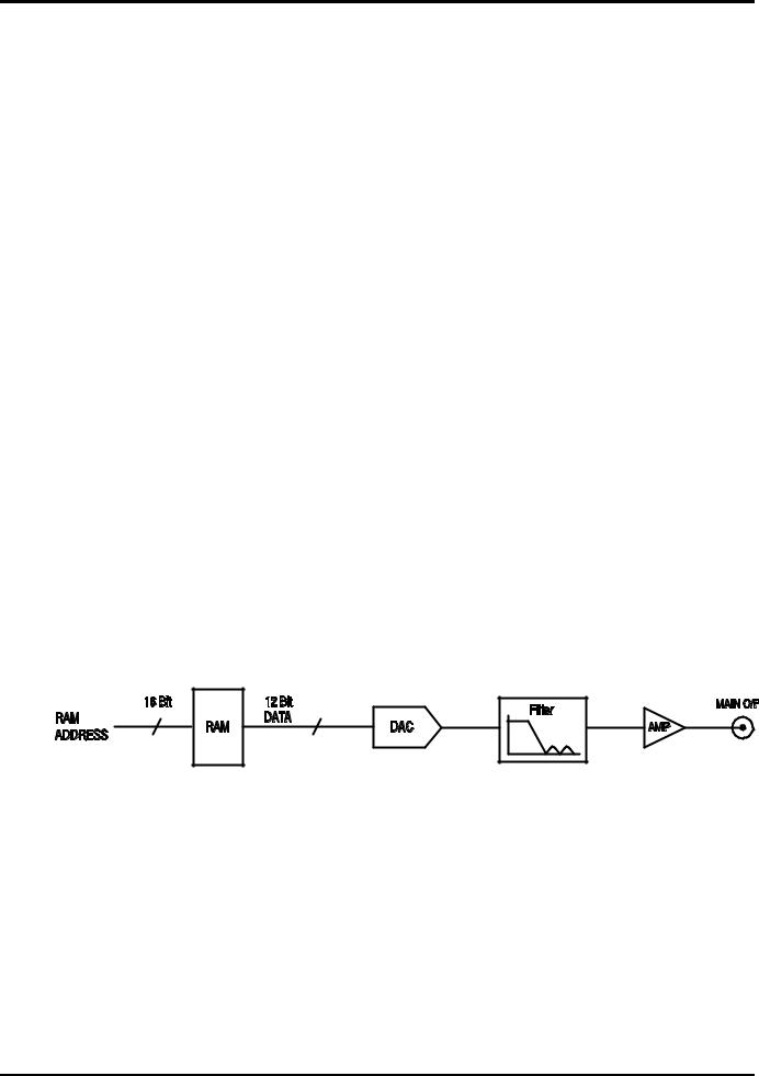
In both modes the waveform data is stored in RAM. As the RAM address is incremented the values are output sequentially to a Digital-to-Analogue Converter (DAC) which reconstructs the waveform as a series of voltages steps which are subsequently filtered before being passed to the main output connector.
The main difference between DDS and Clock Synthesis modes is the way in which the addresses are generated for the RAM and the length of the waveform data.
19

Clock Synthesis Mode
In Clock Synthesis mode the addresses are always sequential (an increment of one) and the clock rate is adjusted by the user in the range 30MHz to 0·1Hz. The frequency of the waveform is clock frequency ÷ waveform length, thus allowing short waveforms to be played out at higher repetition rates than long waveforms, e.g. the maximum frequency of a 4 point waveform is 30e6÷4 or 7·5MHz but a 1000 point waveform has a maximum frequency of 30e6÷1000 or 30kHz.
Arbitrary waveforms have a user defined length of 4 to 65536 points. Squarewaves use a fixed length of 2 points and pulse and pulse train have their length defined by the user selected period value.
DDS Mode
In DDS mode (Direct Digital Synthesis) all waveforms are stored in RAM as 4096 points. The frequency of the output waveform is determined by the rate at which the RAM addresses are changed. The address changes are generated as follows:
The RAM contains the amplitude values of all the individual points of one cycle (360º) of the waveform; each sequential address change corresponds to a phase increment of the waveform of 360º/4096. Instead of using a counter to generate sequential RAM addresses, a phase accumulator is used to increment the phase.
On each clock cycle the phase increment, which has been loaded into the phase increment register by the CPU, is added to the current result in the phase accumulator; the 12 most significant bits of the phase accumulator drive the lower 12 RAM address lines, the upper 4 RAM address lines are held low. The output waveform frequency is now determined by the size of the phase increment at each clock. If each increment is the same size then the output frequency is constant; if it changes, the output frequency changes as in sweep mode.
The generator uses a 38 bit accumulator and a clock frequency which is 238 x 10-4(~27·4878 MHz); this yields a frequency resolution of 0·1 mHz.
Only the 12 most significant bits of the phase accumulator are used to address the RAM. At a waveform frequency of FCLK/4096 (~6·7MHz), the natural frequency, the RAM address increments at every clock. At all frequencies below this (i.e. at smaller phase increments) one or more addresses are output for more than one clock period because the phase increment is not big enough to step the address at every clock. Similarly at frequencies above the natural frequency the larger phase increment causes some addresses to be skipped, giving the effect of the stored waveform being sampled; different points will be sampled on successive cycles of the waveform.
20

Standard Waveform Operation
This sections deals with the use of the instrument as a standard function generator, i.e. generating sine, square, triangle, dc, ramp, haversine, cosine, havercosine and sinx/x waveforms. All but squarewave are generated by DDS which gives 7-digit frequency precision; squarewave is generated by Clock Synthesis which results in only 4-digit frequency resolution. Refer to Principles of Operation in the previous section for a fuller explanation of the differences involved.
The STANDARD WAVEFORMS screen also includes arbitrary and sequence for simplicity of switching between these and standard waveforms; they do, however, have their own screens (accessed by pressing ARB and SEQUENCE respectively) and are described in detail in their appropriate sections. Pulse and pulse-train are also accessed from the ‘standard waveforms’ screen but are sufficiently different to justify their own section in the manual.
Much of the following descriptions of amplitude and offset control, as well as of Mode, Sweep, etc., in following sections, apply to arbitrary and sequence as well as standard waveforms; for clarity, any differences of operation with arbitrary, sequence, pulse and pulse-train are described only in those sections.
Setting Generator Parameters
Waveform Selection
STANDARD WAVEFORMS ♦sine
◊square ◊triangle
Pressing the STD key gives the STANDARD WAVEFORMS screen which lists all the waveforms available; the rotary control or cursor keys can be used to scroll the full list back and forward through the display. The currently selected waveform (sine with the factory defaults setting) is indicated by the filled diamond; the selection is changed by pressing the soft-key beside the required waveform.
Frequency
STANDARD FREQUENCY 10·00000 kHz
♦freq period ◊
Pressing the FREQ key gives the STANDARD FREQUENCY screen. With freq selected as shown above, the frequency can be entered directly from the keyboard in integer, floating point or exponential format, e.g. 12·34 kHz can be entered as 12340, 12340·00, or 1·234 exp 4 etc. However, the display will always show the entry in the most appropriate engineering units, in this case 12·34000 kHz.
With period selected instead of freq the frequency can be set in terms of a period, e.g. 123·4µs can be entered as ·0001234 or 123·4e-6; again the display will always show the entry in the most appropriate engineering units. Note that the precision of a period entry is restricted to 6 digits; 7 digits are displayed but the least significant one is always zero. The hardware is programmed in terms of frequency; when a period entry is made the synthesised frequency is the nearest equivalent value that the frequency resolution and a 6-digit conversion calculation gives. If the frequency is displayed after a period entry the value may differ from the expected value because of these considerations. Further, once the setting has been displayed as a frequency, converting back again to display period will give an exact 6-digit equivalent of the 7-digit frequency, but this may differ from the period value originally entered.
21

Squarewave, generated by Clock Synthesis has 4-digit resolution for both frequency and period entry but the hardware is still programmed in terms of frequency and the same differences may occur in switching the display from period to frequency and back to period.
Turning the rotary control will increment or decrement the numeric value in steps determined by the position of the edit cursor (flashing underline); the cursor is moved with the left and right arrowed cursor keys.
Note that the upper frequency limits vary for the different waveform types; refer to the Specifications section for details.
Frequency setting for arbitrary, sequence pulse and pulse-train is explained in the relevant sections.
Amplitude
AMPLITUDE:
+20·0 Vpp
♦Vpp |
Vrms ◊ |
◊dBm |
load:hiZ ◊ |
Pressing the AMPL key gives the AMPLITUDE screen.
The waveform amplitude can be set in terms of peak-to-peak Volts (Vpp), r.m.s. Volts (Vrms) or dBm (referenced to a 50Ω or 600Ω load). For Vpp and Vrms the level can be set assuming that the output is open-circuit (load:hiZ) or terminated (load:50Ω or load:600Ω); when dBm is selected termination is always assumed and the load:hiZ setting is automatically changed to load:50Ω. Note that the actual generator output impedance is always 50Ω; the displayed amplitude values for 600Ω termination take this into account.
With the appropriate form of the amplitude selected (indicated by the filled diamond) the amplitude can be entered directly from the keyboard in integer, floating point or exponential format, e.g. 250mV can be entered as ·250 or 250 exp -3, etc., However, the display will always show the entry in the most appropriate engineering units, in this case 250mV.
Turning the rotary control will increment or decrement the numeric value in steps determined by the position of the edit cursor (flashing underline); the cursor is moved with the left and right arrowed cursor keys.
Alternate presses of the ± key will invert the MAIN OUT output; if DC OFFSET is non-zero, the signal is inverted about the same offset. The exception to this is if the amplitude is specified in dBm; since low level signals are specified in -dBm (0dBm = 1mW into 50Ω = 224mVrms) the - sign is interpreted as part of a new amplitude entry and not as a command to invert the signal.
Note that for DC, sinx/x, pulse train, arbitrary and sequence amplitude can only be displayed and entered in the Vpp form; further limitations on pulse-train, arbitrary and sequence amplitude are discussed in the appropriate sections.
DC Offset
DC OFFSET:
program +0·00 mVdc (actual +0·00 mVdc)
load:hiZ ◊
Pressing the OFFSET key gives the DC OFFSET screen. The offset can be entered directly from the keyboard in integer, floating point or exponential format, e.g. 100mV can be entered as ·1 or 100 exp -3 etc. However, the display will always show the entry in the most appropriate engineering units, in this case 100mV. During a new offset entry the ± key can be used at any time to set the offset negative; alternate presses toggle the sign between + and -.
22

Turning the rotary control will increment or decrement the numeric value in steps determined by the position of the edit cursor (flashing underline); the cursor is moved by the left and right arrowed cursor keys. Because DC offset can have negative values, the rotary control can take the value below zero; although the display may autorange to a higher resolution if a step takes the value close to zero, the increment size is maintained correctly as the offset is stepped negative. For example, if the display shows
program = +205· mVdc
with the cursor in the most significant digit, the rotary control will decrement the offset in 100mV steps as follows:
program = +205· mVdc program = +105· mVdc program = +5·00 mVdc program = -95·0 mVdc program = -195· mVdc
The actual DC offset at the MAIN OUT socket is attenuated by the fixed-step output attenuator when this is in use. Since it is not obvious when the signal is being attenuated the actual offset is shown in brackets as a non-editable field below the programmed value.
For example, if the amplitude is set to 2·5Vpp the output is not attenuated by the fixed attenuator and the actual DC offset (in brackets) is the same as that set. The DC OFFSET display shows:
DC OFFSET:
program +150· mVdc (actual +150· mVdc)
load:hiZ ◊
If the amplitude is now reduced to 250mVpp which introduces the attenuator, the actual DC offset changes by the appropriate factor:
DC OFFSET:
program +150· mVdc (actual +15·1 mVdc)
load:hiZ ◊
The above display shows that the set DC offset is +150mV but the actual offset is +15.1mV. Note that the actual offset value also takes into account the true attenuation provided by the fixed attenuator, using the values determined during the calibration procedure. In the example displayed the output signal is 250mVpp exactly and takes account of the small error in the -20dB fixed attenuator; the offset is 15.1mV exactly, taking account of the effect of the known attenuation (slightly less than the nominal -20dB) on the set offset of 150mV.
Whenever the set DC offset is modified by a change in output level in this way a warning message that this has happened will be displayed. Similarly, because the DC offset plus signal peak is limited to ± 10V to avoid waveform clipping, a warning message will be displayed if this condition is set. This is explained more fully in the Warnings and Error Messages section.
23

Warnings and Error Messages
Two classes of message are displayed on the screen when an illegal combination of parameters is attempted.
WARNING messages are shown when the entered setting causes some change which the user might not necessarily expect. Examples are:
1.Changing the amplitude from, for example, 2·5 Volts pk-pk to 250mV pk-pk brings in the step attenuator; if a non-zero offset has been set then this will now be attenuated too. The
message DC OFFSET CHANGED BY AMPLITUDE will be shown temporarily on the screen but the setting will be accepted; in this case the actual, attenuated, offset will be shown in brackets below the set value.
2.With the output level set to 10V pk-pk, increasing the DC offset beyond ± 5V will cause
the message DC OFFSET + LEVEL MAY CAUSE CLIPPING. The offset change will be accepted (producing a clipped waveform) and the user may then choose to change the output level or the offset to produce a signal which is not clipped.
(clip?) will show in the display beside AMPLITUDE or DC OFFSET while the clipped condition exists.
ERROR messages are shown when an illegal setting is attempted, most generally a number outside the range of values permitted. In this case the entry is rejected and the parameter setting is left unchanged. Examples are:
1.Entering a frequency of 1MHz for a triangle waveform. The error message:
Frequency out of range for the selected waveform is shown.
2.Entering an amplitude of 25Vpp. The error message:
Maximum output level exceeded is shown.
3.Entering a DC offset of 20V. The error message:
Maximum DC offset exceeded is shown.
The messages are shown on the display for approximately two seconds. The last two messages can be viewed again by pressing the last error… soft-key on the UTILITY screen, see System Operations section.
Each message has a number and the full list appears in Appendix 1.
The default set-up is for all warning and error messages to be displayed and for a beep to sound with each message. This set-up can be changed on the error… menu on the UTILITY screen. The error menu is shown below:
◊error beep: ON
◊error message: ON
 warn beep: ON
◊ warn message: ON
Each feature can be turned ON and OFF with alternate presses of the associated soft-key; the factory default is for all features to be ON. If the setting is changed and is required for future use it should be saved by changing the POWER ON SETTING on the power on… menu of the UTILITY screen to restore last setup.
24

SYNC Output
SYNC OUT is a multifunction CMOS/TTL level output that can be automatically or manually set to be any of the following:
• |
Waveform |
Sync : |
A square wave with 50% duty cycle at the main waveform |
|
|
|
frequency, or a pulse coincident with the first few points of an |
|
|
|
arbitrary waveform. Can be selected for all waveforms. |
• |
Position |
Marker : |
Can be selected for arbitrary waveforms only. Any point(s) on the |
|
|
|
main waveform may have associated marker bit(s) set high or low. |
•Burst Done : Produces a pulse coincident with the last cycle of the burst.
•Sequence Sync : Produces a pulse coincident with the end of a waveform sequence.
•Trigger : Selects the current trigger signal (internal, external or manual).
Useful for synchronising burst or gated signals.
•Sweep Sync : Outputs the sweep trigger signal.
•Phase Lock : Used to lock two or more generators. Produces a positive edge at
the 0º phase point.
The setting up of the signals themselves is discussed in the relevant sections later in this manual, e.g. Trigger is described in the Triggered Burst/Gate section and Position Marker under the Arbitrary Waveform Generation.
Pressing the key above the SYNC OUT socket calls the SYNC OUTPUT SETUP screen.
SYNC OUTPUT SETUP  output: on
◊ mode: auto
 src: waveform sync
SYNC OUT is turned on and off by alternate presses of the output soft-key.
The selection of the signal to be output from the SYNC OUT socket is made using the src (source) soft-key; repeated presses of src cycle the selection through all the choices (waveform sync, position marker, etc.) listed above. Alternatively, with the src selected (double-headed arrow) the rotary control or cursor keys can be used to step backwards and forwards through the choices.
The source selection of the SYNC OUT waveform can be made automatic (auto) or userdefined (manual) with alternate presses of the mode soft-key. In automatic mode the SYNC OUT waveform most appropriate for the current main waveform is selected.
For example, waveform sync is automatically selected for all continuous standard and arbitrary waveforms, but trigger is selected in trigger or gated waveform modes. The automatic selection will be mentioned in each of the appropriate main waveform mode sections and a full table is given in Appendix 2.
The automatic selection can still be changed manually by the src soft-key even when auto mode has been selected but the selection will immediately revert to the automatic choice as soon as any relevant parameter (e.g. main waveform frequency or amplitude) is adjusted. Manual must be selected by the mode soft-key for a source other than the automatic choice to remain set. The auto selection will generally set the most frequently used signal, e.g. waveform sync for all continuous main waveforms, but manual will need to be used for special requirements, e.g. position markers on arbitrary waveforms.
25

Sweep Operation
General
Principles of Sweep Operation
All standard and arbitrary waveforms can be swept with the exception of pulse, pulse-train and sequence. During Sweep all waveforms are generated in DDS mode because this offers the significant advantage of phase-continuous sweeps over a very wide frequency range (up to 1010). However, it must be remembered that the frequency is actually stepped, not truly linearly swept, and thought needs to be given as to what the instrument is actually doing when using extreme combinations of sweep range and time.
For DDS operation during Sweep all waveforms must be 4096 points in length; this is the natural length for standard waveforms but all arbitrary waveforms are expanded or condensed in software to 4096 points when Sweep is turned on. This does not affect the original data.
Sweep mode is turned on and off either by the on or off soft-key on the SWEEP SETUP screen accessed by pressing the SWEEP front panel key, or by the sweep soft-key on the MODE screen.
When sweep is turned on the software creates a table of 2048 frequencies between, and including, the specified start and stop values. For sweep times of 1·03s and greater the sweep will step through all 2048 frequency values. Below 1·03s, however, the frequency sweep will contain fewer steps because of the minimum 0·5ms dwell at each step; at the shortest sweep time (30ms) the sweep will contain only 60 steps.
Because any frequency used in sweep mode must be one of the tabled values, the centre frequency displayed (see Sweep Range) may not be the exact mid-point and markers (see Sweep Marker) may not be exactly at the programmed frequency. The frequency resolution of the steps will be particularly coarse with wide sweeps at the fastest sweep rate.
Connections for Sweep Operation. Sync Out and Trig In
Sweeps are generally used with an oscilloscope or hard-copy device to investigate the frequency response of a circuit. The MAIN OUT is connected to the circuit input and the circuit output is connected to an oscilloscope or, for slow sweeps, a recorder.
An oscilloscope or recorder can be triggered by connecting its trigger input to the generator’s SYNC OUT; SYNC OUT defaults to sweep sync when sweep is turned on. sweep sync goes high at the start of sweep and low at the end of sweep. At the end of sweep it is low long enough for an oscilloscope to retrace, for example.
To show a marker on the display instrument the rear panel CURSOR/MARKER OUT socket should be connected to a second channel. Alternatively, for an oscilloscope the signal can be used to modulate the Z-axis. See Sweep Marker section for setting marker frequency. The cursor/marker polarity and level is set up on the cursor/marker… menu of the UTILITY screen, see System Operations section.
For triggered sweeps, a trigger signal must be provided at the front panel TRIG IN socket or by pressing the MAN/SYNC key or by a remote command. The function of TRIG IN is automatically defaulted to external when triggered sweep is selected; a sweep is initiated by the rising edge of the trigger signal.
The generator does not provide a ramp output for use with X-Y displays or recorders.
26
Loading...