

Page 1

THURLBY THANDAR INSTRUMENTS
INSTRUCTION MANUAL
TG1000 & TG2000
DDS Function Generators
Page 2

Table of Contents
Introduction 2
Specifications 3
Safety 6
EMC 8
Installation 9
Connections 10
Front Panel Connections 10
Rear Panel Connections 11
General 12
Initial Operation 12
Standard Waveform Operation 15
Setting Generator Parameters 15
AUX Output 18
Warnings and Error Messages 19
Sweep Operation 20
General 20
Setting Sweep Parameters 20
Gated Mode 25
Tone Mode 26
FSK 27
Modulation 28
System Operations from the Utility Menu 29
Calibration 31
Equipment Required 31
Calibration Procedure 31
Calibration Routine 32
Remote Calibration 33
Remote Operation 34
USB Interface 38
Remote Commands 39
Maintenance 42
Appendix 1. Warning and Error Messages 43
Appendix 2. Factory System Defaults 44
1
Page 3

This manual is for both the TG2000 and TG1000 function generators. The TG1000 has a
maximum frequency of 10MHz and no remote control capability but is otherwise functionally the
same as the TG2000 20MHz generator. Wherever there are differences in the specification or
operation, the limits for the TG1000 are shown in square brackets [ ] after the TG2000 limits.
This function generator uses direct digital synthesis to provide high performance and extensive
facilities at a breakthrough price. It can generate a variety of waveforms between 1mHz and
20MHz [10MHz] with a resolution of 6 digits and an accuracy better than 10ppm.
Direct digital synthesis for accuracy & stability
Direct digital synthesis (DDS) is a technique for generating waveforms digitally using a phase
accumulator, a look-up table and a DAC. The accuracy and stability of the resulting waveforms is
related to that of the crystal master clock.
The DDS generator offers not only exceptional accuracy and stability but also high spectral purity,
low phase noise and excellent frequency agility.
A wide range of waveforms
High quality sine, square and pulse waveforms can be generated over the full frequency range of
1mHz to 20MHz [10MHz].
Introduction
Triangle waveforms can also be generated but with limitations as to the maximum usable
frequency.
Variable symmetry/duty-cycle is available for squarewave and pulse waveforms.
Sweep
All waveforms can be swept from 0.2Hz to their maximum frequency in a single sweep at a rate
variable between 50 milliseconds and 999 seconds. The sweep is fully phase continuous.
Sweep can be linear or logarithmic, single or continuous. Single sweeps can be triggered from
the front panel, the trigger input, or the digital interfaces. A sweep marker is provided.
AM
External Amplitude Modulation is available for all waveforms.
FSK and Tone modes
Frequency Shift Keying provides phase coherent switching between two selected frequencies; in
Tone mode the output is stepped asynchronously through a user-defined list of up to 16
frequencies. In both modes the switching source can be the internal trigger generator, front panel,
an external signal or a remote command.
Easy and convenient to use
All of the main generator parameters are clearly displayed together on a backlit LCD with 4 rows
of 20 characters. Sub menus are used to set the parameters for each function.
All parameters can be entered directly from the numeric keypad. Alternatively most parameters
can be incremented or decremented using the rotary encoder.
This system combines quick numeric data entry with quasi-analogue adjustment when required.
Fully programmable via USB and Addressable RS-232 (TG2000 only)
The generator has both USB and RS-232 interfaces which can be used for remote control of all of
the instrument functions.
As well as operating in conventional single instrument mode the RS-232 serial interface can also
be used in addressable mode whereby up to 32 units can be linked to a single PC serial port.
2
Page 4

Specifications apply at 18°- 28°C after one hour warm-up, at maximum output into 50Ω.
TG1000 limits, where different, are shown in square brackets [ ] after the TG2000 limits.
WAVEFORMS
Standard waveforms of sine, square, triangle, DC, positive pulse and negative pulse.
Sine
Range: 1mHz to 20MHz [10MHz]
Resolution: 1mHz or 6 digits
Accuracy: 10 ppm for 1 year; ± 1mHz below 0.2Hz
Temperature Stability: Typically <1 ppm/ºC outside 18° to 28°C
Output Level:
Harmonic Distortion: <0.3% THD to 20kHz (typically 0.1%)
Non−harmonic Spurii:
Square
Range: 1mHz to 20MHz [10MHz]
Resolution: 1mHz or 6 digits
Symmetry Control: 20% to 80% (1% resolution) 1mHz to 20MHz [10MHz]
Accuracy: 10 ppm for 1 year; ± 1mHz below 0.2Hz
Output Level:
Rise and Fall Times: <22ns
Aberrations: <5% + 2mV
Specifications
2.5mV to 10Vp−p into 50Ω
<–45dBc to 300kHz
<−35dBc to 20MHz [10MHz] (typically <−40dBc)
<–55dBc to 1MHz, <–55dBc + 6dB/octave 1MHz to 20MHz [10MHz]
2.5mV to 10Vp−p into 50Ω
Triangle
Range: 1mHz to 1 MHz
Resolution: 1mHz or 6 digits
Accuracy: 10 ppm for 1 year; ± 1mHz below 0.2Hz
Output Level:
Linearity Error: <0.5% to 100 kHz
Positive and Negative Pulses
Range: 1mHz to 20MHz [10MHz]
Resolution: 1mHz or 6 digits
Symmetry Control: 20% to 80% (1% resolution) 1mHz to 10MHz
Accuracy: 10 ppm for 1 year; ± 1mHz below 0.2Hz
Output Level:
Rise and Fall Times: <22ns
Aberrations: <5% + 2mV
OPERATING MODES
Continuous
Continuous cycles of the selected waveform are output at the programmed frequency.
2.5mV to 10Vp−p into 50Ω
1.25mV to 5Vp-p into 50Ω positive or negative only pulses, with respect
to the DC Offset baseline.
3
Page 5

Gated
Non-phase coherent gating - output carrier wave is on while Gate signal is high and off while low.
Carrier frequency: From 1mHz to 20MHz [10MHz].
Carrier waveforms: All
Trigger rep. rate: DC to 100 kHz external; to 5kHz using internal trigger generator.
Gate signal source: Manual (front panel MAN TRIG key), external signal (TRIG/GATE IN),
Sweep
Carrier Waveforms: All
Sweep Mode: Linear or logarithmic, single or continuous.
Sweep Width:
Sweep Time: 50ms to 999s (3 digit resolution).
Marker: Available from AUX output. Variable during sweep.
Sweep Trigger Source: The sweep may be free run or triggered from any of the following sources:
External Amplitude Modulation
Carrier Frequency: From 1mHz to 20MHz [10MHz].
Carrier Waveforms: All
Modulation Source: VCA IN socket
Frequency Shift Keying (FSK)
Phase coherent switching between two selected frequencies at a rate defined by the switching
signal source.
Carrier frequency: From 1Hz to 20MHz [10MHz].
Carrier waveforms: All
Switch repetition rate: DC to 5kHz (internal trigger) or DC to 1MHz (external trigger).
Switching signal source: Manual (front panel MAN TRIG key), internal trigger generator, external
Tone
The tone is output while the trigger signal is high and stopped while the trigger signal is low. The
next tone is output when the trigger signal is high again.
Carrier Waveforms: All
Frequency List:
Switching Source: Manual (front panel MAN TRIG key), internal trigger generator, external
Min Switching Time: 1ms per tone
internal gate generator or remote interface.
From 0.2Hz to 20MHz [10MHz] in one range. Phase continuous.
Independent setting of the start and stop frequency.
Manual (front panel MAN TRIG key), external from TRIG/GATE IN or from
remote interface.
signal (TRIG/GATE IN) or remote interface.
Up to 16 frequencies from 1Hz to 20MHz
signal (TRIG/GATE IN) or remote interface.
[10MHz]
OUTPUTS
Main Output
Output Impedance:
Amplitude:
Amplitude Accuracy:
Amplitude Flatness: ±0.2dB to 500kHz; ±2dB to 20MHz [±1dB to 10MHz].
4
50Ω or 600Ω
5mV to 20V pk-pk open circuit, (2.5mV to 10V pk-pk into 50Ω/600Ω).
Output can be specified as HiZ (open circuit value) or V (voltage into
characteristic impedance) in pk-pk, r.m.s. or dBm.
±3% ±1mV at 1kHz into 50Ω/600Ω.
Page 6

DC Offset Range:
DC Offset Accuracy: typically ±3% ±10mV, unattenuated.
Resolution: 3 digits for both Amplitude and DC Offset.
Pulse Aberrations: <5% + 2mV.
Aux Out
Multifunction output user definable or automatically selected to be any of the following:
Waveform Sync: A square wave at the main waveform frequency. Symmetry is 50% for
Trigger: Outputs a replica of the current trigger signal.
Sweep Sync: Outputs a trigger signal at the start of sweep to synchronize an
Output Signal Level:
INPUTS
Ext Trig /Gate
Frequency Range: DC - 1MHz for FSK; DC – 100kHz for Gate; DC – 2.5kHz for Tone and
Signal Range: Threshold nominally TTL level; maximum input ±10V.
Minimum Pulse Width: 100ns for Gate and FSK modes; 0.2ms for Sweep and Tone modes.
Input Impedance:
VCA In
Frequency Range: DC - 100kHz.
Signal Range: 2.5V for 100% level change at maximum output.
Input Impedance:
INTERFACES (TG2000 only)
RS-232: Variable Baud rate, 19200 Baud maximum. 9-pin D-connector.
USB: Standard USB hardware connection.
GENERAL
Display: 20 character x 4 row alphanumeric LCD.
Data Entry: Keyboard selection of mode, waveform etc.; value entry direct by
Stored Settings: Up to 9 complete instrument set-ups may be stored and recalled from
Size: 260(W) x 88(H) x 235(D)
Weight: 2kg. (4.5lb.)
Power: 110-120V AC or 220V-240V AC ±10%, 50/60Hz,
Operating Range: +5°C to 40°C, 20-80% RH.
Storage Range: -20°C to + 60°C.
Environmental: Indoor use at altitudes up to 2000m, Pollution Degree 2.
Safety & EMC: Complies with EN61010-1 & EN61326.
±10V. DC offset plus signal peak limited to ±10V from 50Ω/600Ω.
sine and triangle waves at MAIN OUT; for square waves and pulses
symmetry is the same as that of the waveform at MAIN OUT.
oscilloscope. Can additionally output a sweep marker.
Output impedance 50Ω nominal. Logic levels of <0.8V & >3V, except
for Sweep Sync. Sweep Sync is a 3-level waveform: low at start of
sweep, high for the duration of the last frequency step at end of sweep,
with a narrow 1V pulse at the marker point.
Sweep.
10kΩ
typically 6kΩ.
As well as operating in a conventional RS-232 mode the interface can
be operated in addressable mode whereby up to 32 instruments can be
addressed from one RS-232 port.
numeric keys or by rotary control.
non-volatile memory.
adjustable internally; 35VA max. Installation Category II.
5
Page 7
Safety
This generator is a Safety Class I instrument according to IEC classification and has been
designed to meet the requirements of EN61010−1 (Safety Requirements for Electrical Equipment
for Measurement, Control and Laboratory Use). It is an Installation Category II instrument
intended for operation from a normal single phase supply.
This instrument has been tested in accordance with EN61010−1 and has been supplied in a safe
condition. This instruction manual contains some information and warnings which have to be
followed by the user to ensure safe operation and to retain the instrument in a safe condition.
This instrument has been designed for indoor use in a Pollution Degree 2 environment in the
temperature range 5°C to 40°C, 20% − 80% RH (non−condensing). It may occasionally be
subjected to temperatures between +5° and −10°C without degradation of its safety. Do not
operate while condensation is present.
Use of this instrument in a manner not specified by these instructions may impair the safety
protection provided. Do not operate the instrument outside its rated supply voltages or
environmental range.
WARNING! THIS INSTRUMENT MUST BE EARTHED
Any interruption of the mains earth conductor inside or outside the instrument will make the
instrument dangerous. Intentional interruption is prohibited. The protective action must not be
negated by the use of an extension cord without a protective conductor.
When the instrument is connected to its supply, terminals may be live and opening the covers or
removal of parts (except those to which access can be gained by hand) is likely to expose live
parts. The apparatus shall be disconnected from all voltage sources before it is opened for any
adjustment, replacement, maintenance or repair.
Any adjustment, maintenance and repair of the opened instrument under voltage shall be avoided
as far as possible and, if inevitable, shall be carried out only by a skilled person who is aware of
the hazard involved.
If the instrument is clearly defective, has been subject to mechanical damage, excessive moisture
or chemical corrosion the safety protection may be impaired and the apparatus should be
withdrawn from use and returned for checking and repair.
Make sure that only fuses with the required rated current and of the specified type are used for
replacement. The use of makeshift fuses and the short−circuiting of fuse holders is prohibited.
Do not wet the instrument when cleaning it and in particular use only a soft dry cloth to clean the
LCD window.
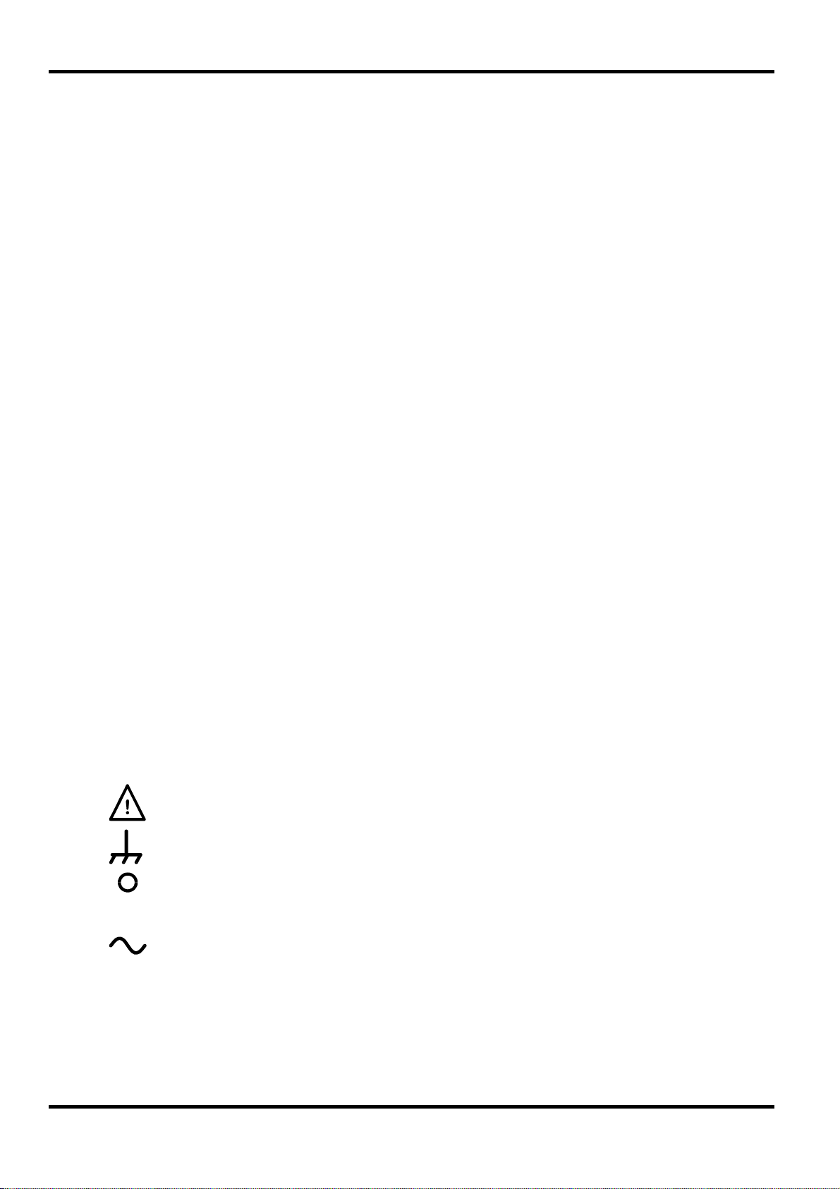
The following symbols are used on the instrument and in this manual:−
6
l
Caution −refer to the accompanying documentation, incorrect operation may
damage the instrument.
terminal connected to chassis ground.
mains supply OFF.
mains supply ON.
alternating current.
Page 8

EC Declaration of Conformity
We Thurlby Thandar Instruments Ltd
Glebe Road
Huntingdon
Cambridgeshire PE29 7DR
England
declare that the
TG1000 & TG2000 DDS Function Generators
meet the intent of the EMC Directive 2004/108/EC and the Low Voltage Directive 2006/95/EC.
Compliance was demonstrated by conformance to the following specifications which have been
listed in the Official Journal of the European Communities.
EMC
Emissions: a) EN61326-1 (2006) Radiated, Class B
b) EN61326-1 (2006) Conducted, Class B
c) EN61326-1 (2006) Harmonics, referring to EN61000-3-2 (2006)
Immunity: EN61326-1 (2006) Immunity Table 1, referring to:
a) EN61000-4-2 (1995) Electrostatic Discharge
b) EN61000-4-3 (2006) Electromagnetic Field
c) EN61000-4-11 (2004) Voltage Interrupt
d) EN61000-4-4 (2004) Fast Transient
e) EN61000-4-5 (2006) Surge
f) EN61000-4-6 (2007) Conducted RF
Performance levels achieved are detailed in the user manual.
Safety
EN61010-1 Installation Category II, Pollution Degree 2.
CHRIS WILDING
TECHNICAL DIRECTOR
2 March 2010
7
Page 9

This instrument has been designed to meet the requirements of the EMC Directive 2004/108/EC.
Compliance was demonstrated by meeting the test limits of the following standards:
Emissions
EN61326-1 (2006) EMC product standard for Electrical Equipment for Measurement, Control and
Laboratory Use. Test limits used were:
a) Radiated: Class B
b) Conducted: Class B
c) Harmonics: EN61000-3-2 (2006) Class A; the instrument is Class A by product category.
Immunity
EN61326-1 (2006) EMC product standard for Electrical Equipment for Measurement, Control and
Laboratory Use.
Test methods, limits and performance achieved are shown below (requirement shown in
brackets):
a) EN61000-4-2 (1995) Electrostatic Discharge : 4kV air, 4kV contact, Performance A (B).
EMC
b) EN61000-4-3 (2006) Electromagnetic Field:
c) EN61000-4-11 (2004) Voltage Interrupt: ½ cycle and 1 cycle, 0%: Performance A (B);
d) EN61000-4-4 (2004) Fast Transient, 1kV peak (AC line only; signal connections <3m,
e) EN61000-4-5 (2006) Surge, 0·5kV (line to line), 1kV (line to ground), Performance A (B).
f) EN61000-4-6 (2007) Conducted RF, 3V, 80% AM at 1kHz (AC line only; signal
connections <3m, therefore not tested), Performance A (A).
According to EN61326 the definitions of performance criteria are:
Performance criterion A: ‘During test normal performance within the specification limits.’
Performance criterion B: ‘During test, temporary degradation, or loss of function or
performance which is self-recovering’.
Performance criterion C: ‘During test, temporary degradation, or loss of function or
performance which requires operator intervention or system reset occurs.’
Cautions
To ensure continued compliance with the EMC directive the following precautions should be
observed:
3V/m, 80% AM at 1kHz, 80MHz – 1GHz: Performance A (A) and 1.4GHz to 2GHz:
Performance A (A); 1V/m, 2.0GHz to 2.7GHz: Performance A (A).
25 cycles, 70%: Performance A (C); 250 cycles, 0%: Performance B (C).
therefore not tested), Performance A (B).
8
a) connect the generator to other equipment using only high quality, double−screened cables. For
the purposes of EMC testing it is assumed that signal connections from the instrument will be
<3m and therefore immunity tests for signal lines (Fast Transient and Conducted RF) have
been omitted.
b) after opening the case for any reason ensure that all signal and ground connections are
remade correctly before replacing the cover. Always ensure all case screws are correctly
refitted and tightened.
c) In the event of part replacement becoming necessary, only use components of an identical
type, see the Service Manual.
Page 10

Mains Operating Voltage
Check that the instrument operating voltage marked on the rear panel is suitable for the local
supply. Should it be necessary to change the operating voltage, proceed as follows:
1) Disconnect the instrument from all voltage sources.
2) Unclip the front bezel by gently pulling the centre of each long edge up and forward.
The case halves are held together by 4 plastic push-rivets. Use the blade of a small
screwdriver in the slot beside each rivet to first ease out the rivet head and then fully remove
the rivet body. Separate the case halves. Visit www.tti-test.com
3) Remove the screws securing the pcb to the case lower and lift out the pcb with front and rear
panels attached; lift one side of the pcb at a time, with the case pcb clips on that side pulled
clear of the pcb edge.
4) Change the voltage settings by changing the soldered links beside the transformer:
For 230V operation fit link LK2 only
For 115V operation fit links LK1 and LK3 only
5) Reassemble in the reverse order.
Installation
for further details.
6) To comply with safety standard requirements the operating voltage marked on the rear panel
must be changed to clearly show the new voltage setting.
7) Change the fuse to suit the new operating voltage, see below.
Fuse
Ensure that the correct mains fuse is fitted for the set operating voltage. The correct mains fuse
types are:
The use of makeshift fuses or the short−circuiting of the fuse holder is prohibited.
Mains Lead
Connect the instrument to the AC supply using the mains lead provided. Should a mains plug be
required for a different mains outlet socket, a suitably rated and approved mains lead set should
be used which is fitted with the required wall plug and an IEC60320 C13 connector for the
instrument end. To determine the minimum current rating of the lead-set for the intended AC
supply, refer to the power rating information on the equipment or in the Specification.
Any interruption of the mains earth conductor inside or outside the instrument will make the
instrument dangerous. Intentional interruption is prohibited.
for 230V operation: 250 mA (T) 250V HRC
for 100V or 115V operation: 500 mA (T) 250V HRC
WARNING! THIS INSTRUMENT MUST BE EARTHED.
9
Page 11
Front Panel Connections
MAIN OUT
This is the output from the main generator; output source impedance can be set to 50Ω or 600Ω.
It will provide up to 20V peak−to−peak e.m.f. which will yield 10V peak-to-peak into a matched
load. To maintain waveform integrity only 50Ω cable should be used and the receiving end should
be terminated with a 50Ω load. It can tolerate a short circuit for 60 seconds.
Do not apply external voltages to these outputs.
AUX OUT
This is a TTL/CMOS level output which may be set to any of the following signals from the
AUX OUT screen.
Connections
waveform sync
Trigger
Sweep sync
AUX OUT logic levels are nominally 0V and 5V from typically 50Ω. AUX OUT will withstand a
short circuit.
Do not apply external voltage to this output.
TRIG/GATE IN
This is the external input for Trigger, Gate and Sweep operations.
Do not apply external voltages exceeding ±10V.
A sync signal phase coincident with the MAIN OUT waveform. For sine
and triangle waves the sync waveform rising edge is at the 0º phase
point of MAIN OUT and the falling edge is at the 180º phase point. For
square waves and pulses both phase and symmetry are coincident with
MAIN OUT.
Provides a replica version of the actual trigger signal; internal, external,
manual and remote all produce a trigger sync.
Goes low at the start of sweep and high at the last frequency step of
the sweep. In addition, a 1/4-amplitude marker pulse can be output at
a specified marker frequency.
VCA IN
10
This is the input socket for external amplitude modulation.
Do not apply external voltages exceeding ±10V.
Page 12

Rear Panel Connections (TG2000 only)
RS-232
9−pin D−connector compatible with addressable RS-232 use. The pin connections are shown
below:
Pin Name Description
USB
1
−
2 TXD Transmitted data from instrument
3 RXD Received data to instrument
4
−
5 GND Signal ground
6
−
7 RXD2 Secondary received data
8 TXD2 Secondary transmitted data
9 GND Signal ground
No internal Connection
No internal connection
No internal connection
Pin 2, 3 and 5 may be used as a conventional RS-232 interface with XON/XOFF handshaking.
Pins 7, 8 and 9 are additionally used when the instrument is used in addressable RS-232 mode.
Signal grounds are connected to instrument ground. The RS-232 address is set from the
remote menu on the UTILITY screen, see System Operations section.
The USB port accepts a standard USB cable. The Windows plug-and-play functions should
automatically recognise that the instrument has been connected.
11
Page 13

Initial Operation
This section is a general introduction to the organisation of the instrument and is intended to be
read before using the generator for the first time. Detailed operation is covered in later sections
starting with Standard Waveform Operation.
In this manual front panel keys and sockets are shown in capitals, e.g. STATUS, AUX OUT; all
soft−key labels, entry fields and messages displayed on the LCD are shown in a different
type−font, e.g
DDS Principles
In this instrument waveforms are generated by Direct Digital Synthesis (DDS). A phase
accumulator is incremented at a rate proportional to the required output frequency. The most
significant 12 bits of the accumulator are used to address a look-up table ROM that converts the
phase information into sinewave amplitude data; this data is then passed to a 10-bit Digital-toAnalogue Converter (DAC) which produces the output waveform. For triangle waves the ROM
look-up table is by-passed and the phase accumulator output is passed directly to the DAC.
At low frequencies all 4096 points in the output wave are stepped through, but as the frequency
increases points are progressively missed out. Sinewaves and triangles are subsequently filtered
to smooth the steps in the DAC output; this technique ensures good sinewave purity up to the
maximum frequency of the generator but the practical limit to which excellent triangle linearity is
maintained is only about 100kHz. Squarewaves and pulses are derived from the sinewave using
a variable threshold comparator; this permits symmetry control of these waveforms across the
whole instrument frequency range.
. WAVEFORM, sine.
General
The major advantages of DDS over conventional analogue generation are:
• Frequency accuracy and stability is that of the crystal oscillator.
• Frequencies can be set with high resolution from mHz to MHz.
• Low phase noise and distortion.
• Very wide frequency sweeps are possible.
• Fast phase continuous frequency switching.
• In addition, being a digital technique, it is easier to make every parameter programmable from
the keyboard, or remotely via the USB or RS-232 interfaces.
Switching On
Switch on the generator using the ON/OFF switch on the rear panel. To fully disconnect from the
AC supply unplug the mains cord from the back of the instrument or switch off at the AC supply
outlet; make sure that the means of disconnection is readily accessible. Disconnect from the AC
supply when not in use.
At power up the generator displays the installed software revision and conducts a self-test.
Power-on self-test takes a few seconds, after which the status screen is displayed, showing the
generator parameters set to their default values, with the MAIN OUT output set off. Refer to the
System Operations section for how to change the power up settings to either those at power
down or to any one of the stored settings. Recall the status screen at any time with the STATUS
key; a second press returns the display to the previous screen.
12
Change the basic generator parameters as described in the Standard Waveform Operation
section and switch the output on with the ON key; the lamp above the key will light to show that
output is on.
Page 14

Display Contrast
All parameter settings are displayed on the 20 character x 4 row backlit liquid crystal display
(LCD). The contrast may vary a little with changes of ambient temperature or viewing angle but
can be optimised for a particular environment by using the front panel contrast control. Insert a
small screwdriver or trimmer tool through the adjustment aperture marked LCD and rotate the
control for optimum contrast.
Keyboard
Pressing the MENU key calls the top-level menu from which all functions can be accessed.
Selections are made from this menu using the display soft-keys and numeric values are then
changed using the numeric keys or rotary control, see the Principles of Editing section.
The keys are as follows:
• MENU calls the top-level menu screen from which the main functions can be directly
selected. These are WAVEFORM, FREQUENCY, AMPLITUDE, DC OFFSET, SYMMETRY,
MODE, UTILITY and AUX OUT. Pressing the associated soft-key of any of these functions
calls a further screen which permits the parameters of that function to be edited either from
the numeric keypad or by using the rotary control/cursor keys.
• Numeric/Unit keys permit direct entry of a value for the parameter currently selected. Thus,
having selected the FREQUENCY screen (by pressing the FREQUENCY soft-key on the
MENU screen), a new frequency of 100kHz, for example, is set by pressing 1, 0, 0, kHz.
CE (Clear Entry) undoes a numeric entry digit by digit. ESCAPE returns a setting being
edited to its last value.
• Eight soft-keys around the display are used to directly set or select parameters from the
currently displayed menu; their operation is described in more detail in the next section.
• The STATUS key always returns the display to the default start-up screen which gives an
overview of the generator’s status. Pressing STATUS again returns the display to the
previous screen.
Further explanations will be found in the detailed descriptions of the generator’s operation in the
sections that follow.
Status Display
After the messages at switch-on, or at any time the STATUS key is pressed, the Status display is
shown. With the generator set to the factory defaults (Appendix 2), the display will be:
This display gives an overview of the status of the main generator parameters. If a waveform is
selected for which symmetry can be set (see Specification) the additional field of
shown to the right of the waveform type, see example below:
WAVE:sine
FREQ:10·0000kHz CONT
AMPL:+4·00Vpp
DC:+0·00Vdc (+0·00V)
SYMmetry is
WAVE:square SYM:35%
FREQ:10·0000kHz CONT
AMPL:+4·00V
DC:+0·00Vdc (+0·00V)
For convenience, the WAVEFORM, FREQUENCY, AMPLITUDE, DC OFFSET, SYMMETRY and
MODE screens can be directly selected from the Status display, (i.e. without having to first return
to the main MENU) by pressing the appropriate soft-key beside WAVE, FREQ, AMPL, etc.
13
Page 15
Principles of Editing
Each screen called up by pressing a soft-key on the top level MENU display shows parameter
value(s) and/or a list of choices. Choices are made using the soft−key associated with the screen
item to be selected. Parameter values can be edited by using the ROTARY CONTROL in
combination with the left and right arrowed CURSOR keys, or by direct numeric keyboard entry;
The examples which follow assume factory default settings.
A diamond beside a screen item indicates that it is selectable; hollow diamonds identify
deselected items and filled diamonds denote selected items. For example, press the
soft-key on the main menu to get the screen shown below:
The filled diamond indicates that the selected mode is continuous. Gated or sweep
modes are selected by pressing the associated soft−key which will make the diamond beside that
item filled and the diamond beside
ellipsis (three dots following the screen text) indicates that a further screen follows when that item
is selected. In the case of the MODE screen illustrated, pressing the
bottom line brings up the
the
continuous mode selection.
MODE
MODE more…◊
♦continuous
◊ gated setup…◊
◊ sweep setup…◊
continuous hollow. This screen also illustrates how an
setup... soft−key on the
SWEEP SETUP menu; note that selecting this item does not change
Some screen items are marked with a double−headed arrow (a split diamond) when selected to
indicate that the item’s setting can be changed by further presses of the soft−key, by pressing
either cursor key or by using the rotary control. For example, pressing the AUX OUT soft-key on
the main menu brings up the screen shown below.
AUX OUT
output: on
◊ mode: auto
◊ srce: waveform sync
Repeated presses of the output soft-key will toggle the output between on and off.
Similarly when srce (source) is selected, repeated presses of the srce soft-key will step
through all possible selections of the AUX OUT source (
sweep sync
). The rotary control can also be used to step through the selections.
waveform sync, trigger, and
In screens where a parameter with a numeric value is displayed the cursor keys move the edit
cursor (a flashing underline) through the numeric field and the rotary control will increment or
decrement the value; the step size is determined by the position of the edit cursor within the
numeric field. Thus for
FREQUENCY set to 1.00000 MHz rotating the control will change
the frequency in 1kHz steps. Turning the control quickly will step numeric values in multiple
increments.
The display will auto-range up or down as the frequency is changed but the increment size and
displayed units are maintained. In the example above (
the lowest frequency that can be set by rotating the control is 1kHz, shown as
FREQUENCY set to 1.00000 MHz) ,
0.00100 MHz.
The displayed units can be changed at any time by pressing the appropriate key, e.g. pressing
kHz or Hz will change the display for the above example to
1.00000 kHz or 1000.00 Hz
respectively. To reduce the frequency further using the rotary control it is necessary to move the
cursor to set a smaller increment size.
14
Page 16

Standard Waveform Operation
When first switched on, and at all subsequent power-ups, unless specified otherwise on the
UTILITY menu, the generator will be set to the factory defaults (Appendix 2), with the MAIN OUT
off. The basic parameters can be changed as described below.
Setting Generator Parameters
Main Menu
The starting point for changing any parameter is the Main Menu, accessed by pressing the MENU
key.
◊ WAVEFORM SYMMETRY ◊
◊ FREQUENCY MODE ◊
◊ AMPLITUDE UTILITY ◊
◊ DC OFFSET AUX OUT ◊
The set-up screen for each of the principal parameters is displayed by pressing the appropriate
soft-key on this Main Menu; the parameters can then be changed as described below.
Waveform Selection
WAVEFORM
♦sine +pulse ◊
◊ square - pulse ◊
◊ triangle dc only ◊
Pressing the WAVE soft-key on the main menu gives the WAVEFORM screen which lists all the
waveforms available. The currently selected waveform (sine with the factory defaults setting) is
indicated by the filled diamond; the selection is changed by pressing the soft−key beside the
required waveform.
Sine square and triangle are bipolar waveforms centred about the baseline level set from the DC
Offset screen; +pulse and –pulse are uni-polar waveforms that are respectively positive and
negative with respect to the baseline. When
baseline DC voltage only, set from the DC Offset screen.
Frequency
Pressing the FREQ key gives the FREQUENCY screen. With freq selected as shown above,
the frequency can be entered directly from the keyboard in any convenient units, e.g. 12.34kHz
can be entered directly in kHz but can also be entered as 12340Hz or 0.01234MHz.
With
period can be entered directly in any convenient units, e.g. 0.1ms can also be entered as 0.0001s
or 100us. The hardware is actually programmed in terms of frequency and when a period entry is
made the synthesised frequency is the nearest equivalent value that the frequency resolution and
conversion calculation gives. Since the instrument’s frequency resolution is 1mHz there will
generally be no noticeable loss of precision for frequencies above 1kHz (periods <1ms) but the
conversion errors will increase progressively for entries of longer periods; to maintain precision,
low frequencies (<1kHz) should be entered in terms of frequency.
Turning the rotary control will increment or decrement the numeric value in steps determined by
the position of the edit cursor (flashing underline); the cursor is moved with the left and right
arrowed cursor keys.
Note that the upper frequency limits vary for the different waveform types; refer to the
Specifications section for details.
dc only is selected the output ‘waveform’ is the
FREQUENCY
10·0000 kHz
♦freq period ◊
period selected instead of freq the frequency can be set in terms of a period; the
15
Page 17

Amplitude
Pressing the AMPLITUDE soft-key on the main menu gives the AMPLITUDE screen.
The actual source impedance of the generator can be set to either 50Ω (factory default) or 600Ω
with alternate presses of the
600Ω or hiZ (open-circuit) can be selected with successive presses of the
When an amplitude setting is made the selected source impedance and expected load
termination are taken into account such that the actual output amplitude is that shown in the
display.
The waveform amplitude can be set in terms of peak-to-peak Volts (Vpp), r.m.s. Volts (Vrms) or
dBm (referenced to a 50Ω or 600Ω terminating load). The most appropriate units can be selected
with successive presses of the units soft-key, which steps through the three options of
Vrms
automatically changed to
load:50Ω soft-keys will now only toggle between load:50Ω and load:600Ω
settings.
AMPLITUDE
+4·00 Vpp Vpp ◊
◊ srce:50Ω load:hiZ ◊
srce (source) soft-key. In addition, an assumed load of 50Ω,
load soft-key.
Vpp,
and dBm in turn. Note that when dBm is selected a load:hiZ setting is
load:50Ω because a termination is always assumed; pressing the
With the appropriate form of amplitude selected, numeric entries can be made directly from the
keyboard in either mV or Volts, e.g. 250mV can be entered as 250mV or 0.25V. Turning the rotary
control will increment or decrement the numeric value in steps determined by the position of the
edit cursor (flashing underline); the cursor is moved with the left and right arrowed cursor keys.
Alternate presses of the ± key will invert the MAIN OUT output; if DC OFFSET is non−zero, the
signal is inverted about the same offset. The exception to this is if the amplitude is specified in
dBm; since low level signals are specified in −dBm (0dBm = 1mW into 50Ω = 224mVrms) the
− sign is interpreted as part of a new amplitude entry and not as a command to invert the signal.
DC Offset
Pressing the OFFSET key gives the DC OFFSET screen. The offset can be entered directly
from the keyboard in mV or Volts, e.g. 100mV can be entered as 100mV or 0.1V. During a new
offset entry the ± key can be used at any time to set the offset negative; alternate presses toggle
the sign between + and −.
Turning the rotary control will increment or decrement the numeric value in steps determined by
the position of the edit cursor (flashing underline); the cursor is moved by the left and right
arrowed cursor keys. Because DC offset can have negative values, the rotary control can take the
value below zero; although the display may autorange to a higher resolution if a step takes the
value close to zero, the increment size is maintained correctly as the offset is stepped negative.
For example, if the display shows
DC OFFSET
program +0·00 Vdc
(actual +0·00 Vdc)
◊ srce:50Ω load:hiZ ◊
16
program = +205 mVdc
Page 18

with the cursor in the most significant digit, the rotary control will decrement the offset in 100mV
steps as follows:
program = +1
program = +0
program = +205 mVdc
05 mVdc
05 mVdc
program = −0
program = −1
The actual DC offset at the MAIN OUT socket is attenuated by the fixed−step output attenuator
when this is in use. Since it is not obvious when the signal is being attenuated the actual offset is
shown in brackets as a non−editable field below the programmed value.
For example, if the amplitude is set to 2·5Vpp the output is not attenuated by the fixed attenuator
and the actual DC offset (in brackets) is the same as that set. The
DC OFFSET
program +1.50 Vdc
(actual +1.50 Vdc)
◊ srce:50Ω load:hiZ ◊
If the amplitude is now reduced to 250mVpp which introduces the attenuator, the actual DC offset
changes by the appropriate factor:
DC OFFSET
program +1.50 Vdc
(actual +151 mVdc)
◊ srce:50Ω load:hiZ ◊
The above display shows that the set DC offset is +1.50V but the actual offset is +151mV.
Note that the actual offset value also takes into account the true attenuation provided by the fixed
attenuator, using the values determined during the calibration procedure. In the example
displayed the output signal is 250mVpp exactly and takes account of the small error in the
fixed attenuator; the offset is 151.mV exactly, taking account of the effect of the known
attenuation (slightly less than the nominal) on the set offset of 1.50V.
95 mVdc
95 mVdc
DC OFFSET display shows:
Whenever the set DC offset is modified by a change in output level in this way a warning
message that this has happened will be displayed. Similarly, because waveform clipping occurs if
the DC offset plus signal peak exceeds ± 10V, a warning message will be displayed if this
condition is set. This is explained more fully in the Warnings and Error Messages section.
When
DC voltage only, set from this screen. Since there is no switching waveform, the DC level can be
set over the full ± 10V range; the attenuator is automatically used to give a setting resolution
down to 1mV below 1Vdc and the
The source impedance and assumed load can also be set from this screen.
Symmetry
Pressing SYMMETRY on the Main menu gives the SYMMETRY screen.
dc only is selected on the WAVEFORM screen the output ‘waveform’ is the baseline
actual value will always match the program value.
SYMMETRY 50%♦
◊ 20% 60% ◊
◊ 30% 50 % 70% ◊
◊ 40% 80% ◊
17
Page 19

Symmetry can only be varied for squarewave and pulse waveforms; selecting SYMMETRY for
any other waveform will cause the error message
wave
to be displayed before the SYMMETRY screen is shown.
For squarewave and pulse waveforms the symmetry can be set between 20% and 80%
(mark:space). 20%, 30%, etc. can be set directly with the appropriate soft-key or any in-range
value can be set with a 1% resolution by direct numeric entry or by using the rotary control.
AUX Output
AUX OUT is a multifunction CMOS/TTL level output that can be automatically or manually set to
be any of the following:
•
waveform sync : A sync signal phase coincident with the MAIN OUT waveform. For sine
•
trigger : Outputs a replica of the current trigger signal, i.e. the trigger source
•
sweep sync : Outputs the sweep trigger and marker signals.
Symmetry has no effect on this
and triangle waves the sync waveform rising edge is at the 0º phase
point of MAIN OUT and the falling edge is at the 180º phase point. For
square waves and pulses both phase and symmetry are coincident with
MAIN OUT.
selected on the TRIG/GATE SETUP screen.
The setting up of the signals themselves is discussed in the relevant sections later in this manual.
Pressing the AUX OUT key calls the AUX OUT setup screen.
AUX OUT
output: on
◊ mode: auto
◊ srce: waveform sync
AUX OUT is turned on and off by alternate presses of the output soft−key.
The selection of the signal to be output from the AUX OUT socket is made using the
(source) soft−key; repeated presses of srce cycle the selection through the choices
(
waveform sync, etc.) listed above. Alternatively, with the srce selected (double−headed
arrow) the rotary control or cursor keys can be used to step backwards and forwards through the
choices.
The source selection of the AUX OUT waveform can be made automatic (
(
manual) with alternate presses of the mode soft−key. In automatic mode the AUX OUT
waveform most appropriate for the current main waveform is selected.
For example,
waveform sync is automatically selected for continuous waveforms but
auto) or user−defined
srce
trigger is selected in gated waveform mode.
The automatic selection can still be changed manually by the
mode has been selected but the selection will revert to the automatic choice if the mode is
changed.
automatic choice to remain set. The
signal, e.g.
Manual must be selected by the mode soft−key for a source other than the
auto selection will generally set the most frequently used
waveform sync for all continuous main waveforms.
srce soft−key even when auto
18
Page 20

Warnings and Error Messages
Two classes of message are displayed on the screen when an illegal combination of parameters
is attempted.
WARNING messages are shown when the entered setting causes some change which the user
might not necessarily expect. Examples are:
1. Changing the amplitude from, for example, 2·5 Volts pk−pk to 25mV pk−pk brings in the
step attenuator; if a non−zero offset has been set then this will now be attenuated too. The
message DC OFFSET CHANGED BY AMPLITUDE
screen but the setting will be accepted; in this case the actual, attenuated, offset will be
shown in brackets below the set value.
2. With the output level set to 10V pk−pk, increasing the DC offset beyond ± 5V will cause
the message DC OFFSET + LEVEL MAY CAUSE CLIPPING
be accepted (producing a clipped waveform) and the user may then choose to change the
output level or the offset to produce a signal which is not clipped.
(clip?) will show in the display beside AMPLITUDE or DC OFFSET
condition exists.
ERROR messages are shown when an illegal setting is attempted, most generally a number
outside the range of values permitted. In this case the entry is rejected and the parameter setting
is left unchanged. Examples are:
will be shown temporarily on the
. The offset change will
while the clipped
1. Entering a frequency of 2MHz for a triangle waveform. The error message:
Frequency too high for the triangle wave is shown.
2. Entering an amplitude of 25Vpp. The error message:
Number too high – value unchanged is shown.
The messages are shown on the display for approximately two seconds. The last two messages
can be viewed again by pressing the last error... soft−key on the UTILITY screen, see
System Operations section.
Each message has a number and the full list appears in Appendix 1.
The default set−up is for all warning and error messages to be displayed and for a beep to sound
with each message. This set−up can be changed on the
The
error menu is shown below:
error beep: ON
◊
◊ error message: ON
◊ warn beep: ON
◊ warn message: ON
Each feature can be turned ON and OFF with alternate presses of the associated soft−key; the
factory default is for all features to be ON. If the setting is changed and is required for future use it
should be saved by changing the
the UTILITY screen to
restore last setup.
POWER-ON SETTING on the power on... menu of
error... menu on the UTILITY screen.
19
Page 21

General
Principles of Sweep Operation
All waveforms can be swept phase-continuously from 0.2Hz up to the maximum frequency for the
selected waveform. Although the frequency is stepped, not truly swept as in an analogue
generator, the short step interval (100us) gives a close approximation to an analogue instrument
except for the widest sweeps in the shortest time; see the Frequency Stepping Resolution section
for further discussion.
The frequency steps are calculated in real-time using a 2-stage process. Major steps are
calculated every 5ms with full precision; the values calculated follow a linear or log sweep law
depending on the choice made on the
steps are calculated every 100us by linear interpolation for both linear and log sweeps. Linear
interpolation gives a small loss of precision for the minor points of log sweeps but the error is still
less than ±1 digit of the displayed frequency except for the widest sweeps in the shortest time.
The advantage that linear interpolation of the minor points gives is that it is fast enough for all
points (major and minor) to be calculated in real time. This is turn permits Start, Stop and Marker
frequencies to be changed with Sweep still running, making performance much closer to that of
an analogue instrument.
Sweep Operation
SWEEP SPACING menu. Within each major step minor
Sweep mode is turned on and off either by the
(accessed from the Main menu), by the
accessed by pressing
any of the
returns the operating mode to continuous.
SWEEP SETUP sub-menus. Turning sweep off from any of the latter menus always
setup... on the MODE screen, or by the on and off soft-keys on
on and off soft-key on the SWEEP SETUP screen,
sweep soft−key on the MODE screen
Connections for Sweep Operation. Aux Out and Trig In
Sweeps are generally used with an oscilloscope or hard−copy device to investigate the frequency
response of a circuit. The MAIN OUT is connected to the circuit input and the circuit output is
connected to an oscilloscope or, for slow sweeps, a recorder.
An oscilloscope can be triggered by connecting its trigger input to the generator’s AUX OUT; AUX
OUT defaults to
of sweep and high at the last frequency step of the sweep; depending on the sweep time set this
should be long enough for an oscilloscope to retrace, for example.
AUX OUT will additionally output a marker pulse if the marker frequency is set within the sweep
frequency range. See Sweep Marker section for setting marker frequency.
For triggered sweeps, a trigger signal must be provided at the front panel TRIG/GATE IN socket
or by pressing the MAN TRIG key or by a remote command.
The generator does not provide a ramp output for use with X−Y displays or recorders.
sweep sync when sweep is turned on. sweep sync goes low at the start
Setting Sweep Parameters
20
Pressing the sweep setup... soft−key on the MODE screen displays the SWEEP SETUP
screen.
SWEEP SETUP off
◊ range… type… ◊
◊ time… spacing… ◊
◊ manual… marker… ◊
◊
Page 22

Menus for setting up the range, time (sweep rate), type (continuous, triggered, etc.) spacing
(lin/log) and marker position are all accessed from this screen using the appropriate soft−key. In
addition the control screen for manual sweep (i.e. sweeping using the rotary control) is selected
from this screen and Sweep Mode itself is turned on and off with alternate presses of the
and off soft−key; sweep can also be turned on by the sweep soft−key on the MODE
screen.
On all the following menus, pressing the
SETUP
presses of the
always returns the mode to continuous.
Sweep Range
Pressing the range... soft−key calls the SWEEP RANGE screen.
on
done soft−key returns the display to this SWEEP
screen. On all the following menus sweep can be turned on and off with alternate
on and off soft-key. Turning sweep off from this or the following menus
The maximum sweep range for all waveforms is 0.2Hz to 20MHz[10MHz], except triangle
(1MHz). Sweep range can be defined by start and stop frequencies or in terms of a centre
frequency and span. Start
set directly from the keyboard or by using the rotary control; frequencies can be entered with a
resolution of 0.1Hz (or 5 digits) but in sweep mode the instrument operates with an increment
resolution of 0.2Hz and the actual frequency of any particular step will be rounded up to the
nearest 0.2Hz increment. The start frequency must be lower than the stop frequency (but see
Sweep Type for selecting sweep direction).
Pressing the centre/span
frequency and sweep span about that frequency; pressing the start/stop soft−key on that
screen returns the display to the start and stop frequency form of entry.
Note that when the sweep is displayed in terms of centre frequency and span, the span will be
shown to the nearest 0.2Hz increment but the centre frequency can be shown to 0.1Hz
resolution.
Sweep Time
Pressing the time... soft−key calls the SWEEP TIME screen.
SWEEP RANGE off
◊
♦start: 100·00 kHz
◊ stop: 20·000 MHz
◊ centre/span done ◊
and Stop soft−keys permit the two end points of the sweep to be
soft−key changes the screen to permit entry in terms of centre
SWEEP TIME off
◊
0·05 s
done ◊
The sweep time can be set from 0·05s to 999s with 3−digit resolution by direct keyboard entry or
by using the rotary control. The shortest sweep times will have the fewest steps (a 100ms sweep
will have only 1000 steps whereas a 10s sweep will have 100,000 steps) and will consequently
have a coarse stepping resolution with very wide sweeps, see Frequency Stepping Resolution
section for more discussion.
Sweep Type
Pressing the type soft−key calls the SWEEP TYPE screen.
SWEEP TYPE off ◊
mode:continuous
◊ direction: up
◊ sync: on done ◊
21
Page 23

This screen is used to set the sweep mode (continuous; triggered; hold and reset; manual) and
sweep direction.
Successive presses of the direction soft−key select one of the following sweep directions:
up
down
up/down
down/up
The total sweep time is always that set on the
start frequency to stop frequency.
stop frequency to start frequency.
start frequency to stop frequency and back to start frequency.
stop frequency to start frequency and back to stop frequency.
SWEEP TIME screen, i.e. for up/down and
down/up operation the sweep time in each direction is half the total. Similarly the total number
of steps is the same for all choices, i.e. there will be half the number of steps in each direction for
up/down and down/up operation. In the sweep mode descriptions which follow the direction
is assumed to be
continuous mode the generator sweeps continuously between the start and stop
In
frequencies, triggered repetitively by an internal trigger generator whose frequency is determined
by the sweep time setting. At the stop frequency the generator resets to the start frequency after
a delay long enough for an oscilloscope to retrace, for example, and begins a new sweep.
If
sync is set to on (the default) the generator actually steps from the stop frequency to zero
frequency and then starts the next sweep from the first point of the waveform, synchronised to the
(internally generated) trigger signal. This is useful because the sweep always starts from the
same point in the waveform but the waveform discontinuity can be undesirable in some
circumstances, e.g. filter evaluation.
up but all modes can be used with all sweep directions.
With
sync set to off, the frequency steps directly and phase continuously from the stop
frequency to the start frequency but is not synchronised to the software−generated trigger signal.
In
triggered mode the generator holds the output at the start frequency until it recognises a
trigger. When triggered, the frequency sweeps to the stop frequency, resets, and awaits the next
trigger. If
starts a new sweep at the first point of the waveform when the next trigger is recognised. If
sync is set to on the frequency resets to zero frequency (i.e. no waveform) and
sync is set to off the waveform resets to the start frequency and runs at that frequency until
the next trigger initiates a new sweep.
In
hold & reset mode the generator holds the output at the start frequency until it
recognises a trigger; when triggered, the frequency sweeps to the stop frequency and holds. At
the next trigger the output is reset to the start frequency where it is held until the next sweep is
initiated by a further trigger. If
above; if
new sweep at the first point of the waveform.
For
generator, an external signal applied to TRIG IN, pressing the MAN TRIG key on the front panel,
or a remote command. The trigger source is selected on the TRIG/GATE SETUP screen, called
by pressing the
paragraph in the Gated Mode section for further details.
In
manual mode the whole sweep process is controlled from the MANUAL SWEEP screen.
sync is set to on the frequency actually goes to zero at the start and begins each
triggered and hold & reset modes the trigger source can be the internal trigger
gated setup... soft-key on the MODE screen; refer to the Gate Source
sync is set to off the output operates exactly as described
Manual Sweep
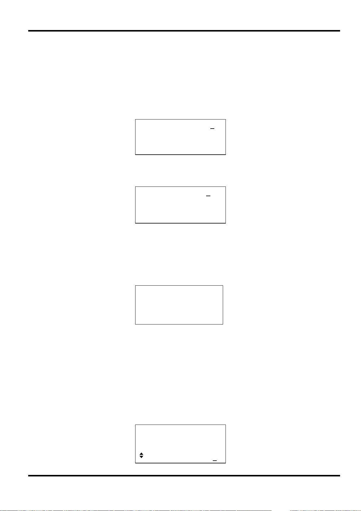
Pressing the manual soft−key on the SWEEP SETUP screen calls the MANUAL SWEEP
screen.
22
MANUAL SWEEP off
1·6308 MHz
◊ wrap:on
◊ res: medium done ◊
◊
Page 24

Before manual control can be used, manual must be selected on the SWEEP TYPE screen,
see above; if
selected
manual has not been set, the message manual sweep mode not
will be displayed before the menu is shown.
In manual mode the frequency can be stepped through the sweep range, defined on the
RANGE
anticlockwise sweeps the frequency down; the direction setting on the SWEEP TYPE
screen is ignored in Manual Sweep mode. The resolution of the frequency steps is set by the
screen, using the rotary control. Clockwise rotation sweeps the frequency up and
resolution soft-key. With res: coarse the sweep range is divided into 100 increments for
the purposes of manual stepping;
10,000 steps. Each complete turn of the rotary knob corresponds to 36 steps; turning the rotary
control rapidly will cause the frequency to jump by more than one step.
The frequency stepping resolution can be changed during a manual sweep such that
resolution can be used to quickly find a frequency of interest and
to step the frequency in smaller increments.
If
wrap is set on the sweep wraps−round from start frequency to stop frequency and
vice−versa; if
depending on the direction of the rotary control.
Sweep Spacing
Pressing the spacing... soft−key on the SWEEP SETUP screen calls the SWEEP
SPACING
SWEEP
medium splits it into 1000 steps and fine splits it into
coarse
fine resolution then selected
wrap is set off the sweep finishes at either the start or stop frequency
screen.
SWEEP SPACING off
♦logarithmic
◊ linear
done ◊
◊
With linear selected the sweep changes the frequency at a linear rate; with logarithmic
selected the sweep spends an equal time in each frequency decade.
Sweep Marker
Pressing the marker... soft−key on the SWEEP SETUP screen calls the MARKER FREQ
screen.
When set to
frequency is set within the sweep frequency range. The marker pulse is approximately 25% of the
amplitude of the sweep sync pulse.
A new marker frequency can be programmed directly from the keyboard or by using the rotary
control and cursor keys. The marker can be programmed to be any frequency within the sweep
range but the actual frequency will be that of the nearest ‘minor’ step, see Principles of Operation
section for an explanation of major and minor frequency steps. The minimum marker duration is
100us (1 minor step) but for longer sweeps the marker duration is increased (in 100us
increments) such that is never less than 1/250th of the complete sweep in order to keep the
marker visible if the whole sweep is displayed on an oscilloscope. Thus for a sweep time of
100ms the marker duration would be 400us. The first 100us increment represents the closest
frequency step to the programmed marker value.
MARKER FREQ off
program:10·0000 MHz
done ◊
◊
sweep sync AUX OUT will additionally output a marker pulse if the marker
The marker will not show if it is programmed to a frequency outside of the sweep range.
23
Page 25

Frequency Stepping Resolution
The generator frequency is stepped, not truly linearly swept, between the Start and Stop
frequencies. The number of discrete frequency steps in a sweep is determined by the sweep
time set on the
resolution, is determined by the number of steps and the sweep range (set on the
RANGE
At the shortest sweep times ( i.e. the fewest steps) with the widest frequency spans the frequency
changes will be quite large at each step; if the output is applied to a filter, for example, the
response will be a succession of step-change levels with (at higher frequencies) many cycles of
the same frequency at each step. This is a limitation of a DDS generator in sweep mode but in
part, of course, this effect can only be created because of the very wide sweeps that can be
achieved with DDS techniques; analogue generators usually have more restricted capabilities.
screen).
SWEEP TIME screen; the size of each step, i.e. the frequency stepping
SWEEP
24
Page 26
General
In Gated mode the generator outputs the waveform whenever the gating signal is high. The
generator is not synchronised with the gate source and the start and stop phase of the generator
waveform is therefore unpredictable. Except for the ability to turn the output signal on and off,
Gated mode is identical to Continuous mode. The same frequency setting is used in the two
modes. This permits the signal to be set up and applied before enabling the Gate.
Gated Mode
Gated mode is turned on by pressing the
MODE soft-key on the main menu.
The selection of the gate source signal is made by pressing the setup... soft-key opposite
gated on the MODE screen:
Gate Source
Successive presses of the source: soft-key on the TRIG/GATE SETUP screen step the
source through the three possible options of
With
front panel MAN TRIG key or by the
gated soft-key on the MODE screen, called by the
MODE more…◊
◊ continuous
♦gated setup…◊
◊ sweep setup…◊
TRIG/GATE SETUP
source: manual
◊ int period: 90.8ms
manual, external and internal.
manual selected the generator output is turned on and off by successive presses of the
∗TRG command from a remote interface.
With
external selected the generator output runs when the signal at the TRIG/GATE IN
socket is high; this input has a TTL level (1.5V) threshold. The minimum pulse width that can be
used in this mode is 100ns and the maximum repetition rate is 100kHz. The maximum signal
level that can be applied without damage is ±10V.
With
internal selected the generator is gated by an internal gate source whose period is set
by selecting
The period can be set from 0.2ms to 999s by direct keyboard entries in ms or seconds. Turning
the rotary control will increment or decrement the numeric value in steps determined by the
position of the edit cursor (flashing underline); the cursor is moved with the left and right arrowed
cursor keys. The internal source is a square wave; the duration of the gate is therefore 0.1ms to
499.5s in step with the source period of 0.2ms to 999s.
int period on the same TRIG/GATE SETUP screen.
AUX OUT in Gate Mode
When Gated mode is selected the AUX OUT source automatically defaults to trigger ;
trigger is a replica of the actual gate signal , i.e. the signal at the TRIG/GATE IN socket, the
internal gate source or the high/low condition ‘toggled’ by alternate presses of the MAN TRIG key
or the
∗TRG remote command.
TRIG/GATE SETUP
◊ source:internal
♦int period: 12.2ms
25
Page 27

General
In Tone mode the output is stepped through a user−defined list of up to 16 frequencies under the
control of the selected trigger source. The frequency list is defined using the
screen and the trigger source is selected on the TRIG/GATE SETUP screen. Tone mode is
turned on using the
Tone Frequency
Press the tone setup... soft−key on the MODE screen, called by pressing the MODE soft-key
on the main menu to get the TONE SETUP screen:
Each frequency in the list can be changed by pressing the appropriate soft−key and entering the
new value from the keyboard. The selected frequency can be deleted from the list by pressing the
del (delete) soft−key. Additional frequencies can be added to the end of the list by selecting
end of list with the appropriate soft−key and entering the new frequency from the keyboard.
Tone Mode
TONE SETUP
tone soft-key on the MODE screen.
TONE SETUP
source as gate setup
◊ 1·00000 kHz #1
♦2·00000 kHz del◊
The whole list can be scrolled back and forward through the display using the rotary control.
Tone Gate Source
The tone frequency steps (changes) when the specified trigger signal goes high and continues
until the level changes again, at which point the output immediately returns to the DC Offset level
specified; the output is then gated off until the next occurrence of the trigger signal at which time
the next frequency in the list is gated on. Note that, just as with Gated mode, the tone frequency
is not synchronised with the tone stepping gate source and the start and stop phase of each tone
is therefore entirely unpredictable.
The trigger signal used for stepping the tone is exactly the same source as that used for Gated
mode and is set up on the TRIG/GATE SETUP screen, called by pressing the
setup
(front panel MAN TRIG key, or remote command), an external signal applied to the
TRIG/GATE IN socket, or
Source paragraph in the Gated Mode section for selection of the trigger source.
When
frequency that is recommended (applied to the TRIG/GATE IN socket) is 1kHz.
... soft-key on the MODE screen. The tone switching trigger source can be manual
external is the selected tone stepping trigger source the maximum switching
gated
internal from the internal trigger generator. Refer to the Gate
26
Page 28

General
FSK (Frequency Shift Keying) mode permits fast phase-continuous switching between two
frequencies within the range of 1Hz to 20MHz [10MHz]. All other parameters of the waveform
(amplitude, offset, symmetry) remain the same as the frequency is switched.
FSK
FSK mode is turned on by pressing the
the
MODE soft-key on the main menu.
Frequency Setting
The two frequencies f0 and f1 , between which the waveform is switched, are set on the
FSK FREQUENCIES screen, called by pressing the
screen.
With each frequency selected in turn (filled diamond) the frequency can be set using direct
numeric keyboard entries or by using the cursor keys and rotary control.
Trigger Source
The trigger source is the same source as that used for Gated and Tone modes and is accessed
and set up in the same way from the
gated setup... soft-key on the MODE screen.
For an external trigger,
is the frequency output with the TRIG/GATE IN signal high.
FSK soft-key on the MODE screen, called by pressing
FSK set-up... soft-key on the MODE
FSK FREQUENCIES
source as gate setup
♦f0: 1·000 kHz
◊ f1: 10·0000 kHz
TRIG/GATE SETUP screen, called by pressing the
f0 is the frequency output with the TRIG/GATE IN signal low and f1
27
Page 29

Modulation
Amplitude Modulation of the carrier is possible by applying a suitable signal (which can be AC
coupled if required) to the front panel VCA IN socket. A positive voltage increases the output
amplitude and a negative voltage decreases the amplitude. The modulating signal is applied at
the appropriate level to obtain the modulation depth required at the set output amplitude. If the
output amplitude is changed the amplitude of the modulating signal will have to be changed if the
same modulation depth is to be maintained. Note that clipping will occur if the combination of
amplitude setting and VCA IN signal attempts to drive the output above 20Vpp open-circuit
voltage (10Vpp into 50Ω).
The VCA IN signal is applied to the amplifier chain prior to the output attenuators. The amplifier
itself is controlled over a limited range (~10dB) and the full amplitude range is achieved by
switching in up to five –10dB attenuation stages. Peak modulation cannot exceed the maximum
of the ‘range’ within which the output has been set by choice of amplitude setting. It is up to the
user to observe the waveforms when using external VCA and to make adjustments if the
waveform is clipping.
Within each ‘range’ the maximum output setting at which clipping is avoided is reduced from
range maximum to half this value as modulation is increased from 0% to 100%; 100% modulation
will be achieved at this mid-range setting with a VCA IN signal of approximately 2.5Vpp.
Any waveform can be modulated, including DC. Modulation frequency range is DC to 100kHz.
Modulating the generator with a squarewave gives step changes in the output amplitude which
are suitable for testing signal compressors and automatic gain control circuits.
Suppressed Carrier Modulation can be achieved by first DC biasing the VCA IN sufficient to
suppress the carrier and then applying the modulating signal.
28
Page 30
System Operations from the Utility Menu
Pressing the UTILITY soft-key on the main menu calls a list of further menus which give access
to various system operations including storing/recalling set−ups from non−volatile memory, error
messages, power-on settings and calibration.
Storing and Recalling Set-ups
Complete waveform set−ups can be stored to or recalled from non−volatile RAM using the menus
called by the store... and recall... soft−keys on the UTILITIES screen.
Pressing store... calls the store screen:
Save to store No: 1
◊ execute
Nine stores, numbered 1 to 9 inclusive, are available. Select the store using the rotary control or
direct keyboard entry and press execute to implement the store function.
Pressing recall... calls the recall screen:
Recall store No: 1
◊ set defaults
◊ execute
In addition to the user−defined stores, the factory defaults can be reloaded by pressing the
set defaults soft−key. Note that loading the defaults does not change the set−ups stored in
memories 1 to 9, or the RS-232/USB interface settings.
Warnings and Error messages
The default setup is for all warning and error messages to be displayed and for a beep to sound
with each message. This setup can be changed on the error... menu:
error beep: ON
◊
◊ error message: ON
◊ warn beep: ON
◊ warn message: ON
Each feature can be turned ON or OFF with alternate presses of the appropriate soft−key.
The last two error messages can be viewed by pressing the last error... soft−key on the
UTILITIES screen. Each message has a number and the full list appears in Appendix 1. See
also Warnings and Error Messages in the Standard Waveform Operation section.
Remote Interface Setup
Pressing remote... calls the REMOTE SETUP screen which permits RS-232/USB choice and
selection of address and Baud rate. Full details are given in the Remote Operation section.
Power On Setting
Pressing the power on... soft−key calls the POWER ON SETTING screen:
POWER ON SETTING
◊ default values
◊ restore last setup
recall store no. 1
29
Page 31

The setting loaded can be selected with the appropriate soft−key to be default values (the
default setting), restore last setup (i.e. the settings at power down are restored at power
up) or any of the settings stored in non−volatile memories 1 to 9. Default values restores
the factory default settings, see Appendix 2.
Calibration
Pressing calibrate... calls the calibration routine, see Calibration section.
30
Page 32

All parameters can be calibrated without opening the case, i.e. the generator offers ‘closed−box’
calibration. All adjustments are made digitally with calibration constants stored in Flash. The
calibration routine requires only a DVM, an oscilloscope and a frequency counter and takes no
more than a few minutes.
The crystal in the timebase is pre−aged but a further ageing of up to ±5ppm can occur in the first
year. Since the ageing rate decreases exponentially with time it is an advantage to recalibrate
after the first 6 month’s use. Apart from this it is unlikely that any other parameters will need
adjustment.
Calibration should be carried out only after the generator has been operating for at least 30
minutes in normal ambient conditions.
Equipment Required
• 3½ digit DVM with 0·25% DC accuracy and 0·5% AC accuracy at 1kHz.
• Frequency counter capable of measuring 20·00000MHz.
• An oscilloscope for the Symmetry adjustment (CAL 13 & CAL14).
The DVM is connected to the MAIN OUT and the counter to the AUX OUT.
Frequency meter accuracy will determine the accuracy of the generator’s clock setting and
should ideally be ±1ppm.
Calibration
Calibration Procedure
The calibration procedure is accessed by pressing the calibrate... soft−key on the
UTILITIES screen.
The software provides for a 4−digit password in the range 0000 to 9999 to be used to access the
calibration procedure. If the password is left at the factory default of 0000 no messages are
shown and calibration can proceed as described in the Calibration Routine section; only if a
non−zero password has been set will the user be prompted to enter the password.
Setting the Password
On opening the Calibration screen press the password... soft−key to show the password
screen:
CALIBRATION SELECTED
Are you sure ?
◊ password… tests…◊
◊ exit continue ◊
ENTER NEW PASSWORD
----
Enter a 4−digit password from the keyboard; the display will show CONFIRM NEW PASSWORD.
Re-enter the password; the display will show the message NEW PASSWORD STORED! for two
seconds and then revert to the UTILITIES menu. If any keys other than 0−9 are pressed while
entering the password, or if the password is re-entered incorrectly, the message ILLEGAL
PASSWORD! will be shown.
31
Page 33

Using the Password to Access Calibration or Change the Password
With the password set, pressing calibration... on the UTILITIES screen will now
show:
ENTER PASSWORD
----
When the correct password has been entered from the keyboard the display changes to the
opening screen of the calibration routine and calibration can proceed as described in the
Calibration Routine section. If an incorrect password is entered the message
PASSWORD! is shown for two seconds before the display reverts to the UTILITIES menu.
With the opening screen of the calibration routine displayed after correctly entering the password,
the password can be changed by pressing
password... soft−key and following the procedure
described in Setting the Password. If the password is set to 0000 again, password protection is
removed.
The password is held in Flash. In the event of the password being forgotten, contact the
manufacturer for help in resetting the instrument.
Calibration Routine
INCORRECT
The calibration procedure proper is entered by pressing continue on the opening Calibration
screen; pressing
exit returns the display to the UTILITIES menu. At each step the display
changes to prompt the user to adjust the rotary control or cursor keys, until the reading on the
specified instrument is at the value given. The cursor keys provide coarse adjustment, and the
rotary control fine adjustment. Pressing
pressing
previous decrements back to the previous step. Alternatively, pressing exit
returns the display to the last CAL screen at which the user can choose to either
values,
recall old values or calibrate again.
next increments the procedure to the next step;
save new
The first two displays specify the connections and adjustment method. The subsequent displays,
CAL 01 to CAL 15, permit all adjustable parameters to be calibrated.
The full procedure is listed below; the name of the control signal being adjusted at each step and
the default DAC value are shown in brackets. The display itself shows a summary of the step
adjustment procedure and the actual DAC value.
CAL 01
Output DC offset zero; adjust for 0V ± 5mV (DCOFFSET, 0007).
CAL 02 Output DC offset +ve full scale; adjust for 10V ± 20mV (DCOFFSET, -1973).
CAL 03 Output DC offset -ve full scale; check for -10V ± 20mV (DCOFFSET, 1959).
CAL 04
Multiplier control zero offset; adjust for minimum output (AMPL, 0008).
CAL 05 Multiplier offset; adjust for 0V +/-5mV (MULTOFST –1494).
CAL 06 Squarewave, note offset.
CAL 07
Waveform offset; adjust for CAL06 value ± 10mV (WAVOFST, -0293).
CAL 08 Waveform full-scale; adjust for 10V +/-10mV (AMPL, 1814).
CAL 09
Squarewave full scale; adjust for 10V ± 10mV (SQLEVEL, 0701).
CAL 10 –20dB output attenuator; adjust for 1V ± 1mV (AMPL, 1813).
CAL 11
CAL 12
–40dB output attenuator; adjust for 0·1V ± 0·1mV (AMPL, 1818).
–10dB intermediate attenuator; adjust for 3.16V ±10mV (AMPL 1798).
CAL 13 Squarewave symmetry (50%); adjust for 50us ± 0·1us (SYM, 0000). 10kHz
CAL 14
CAL 15
Squarewave symmetry (75%); adjust for 75us ± 0·1us (SYM, -0513). 10kHz
Clock calibrate. 10MHz at main and aux outputs; adjust to ±1ppm. Fail if outside
these limits, ±1700 shown on the display (CLKCAL).
32
Page 34

Each adjustment step allows the processor to calculate a calibration constant which is stored in
Flash. Because each step allows a very wide adjustment range it is possible to stop the
instrument functioning completely; if this is suspected the default values listed above should be
set and a complete recalibration should then be performed.
Remote Calibration
Calibration of the instrument may be performed over the RS-232 or USB interface. To completely
automate the process the multimeter and frequency meter will also need to be remote controlled
and the controller will need to run a calibration program unique to this instrument.
The remote calibration commands allow a simplified version of manual calibration to be
performed by issuing commands from the controller. The controller must send the CALADJ
command repeatedly and read the DMM or frequency meter until the required result for the
selected calibration step is achieved. The CALSTEP command is then issued to accept the new
value and move to the next step.
While in remote calibration mode very little error checking is performed and it is the controller’s
responsibility to ensure that everything progresses in an orderly way. Only the following
commands should be used during calibration.
WARNING: Using any other commands while in calibration mode may give unpredictable results
and could cause the instrument to lock up, requiring the power to be cycled to regain control.
CALIBRATION <cpd> [,nrf]
START Enter calibration mode; this command must be issued before any
SAVE Finish calibration, save the new values and exit calibration mode.
ABORT Finish calibration, do not save the new values and exit calibration
CALADJ <nrf> Adjust the selected calibration value by <nrf>. The value must be in
CALSTEP Step to the next calibration point.
For general information on remote operation and remote command formats, refer to the following
sections.
The calibration control command. <cpd> can be one of three
sub−commands:−
other calibration commands will be recognised.
mode.
<nrf> represents the calibration password. The password is only
required with CALIBRATION START and then only if a non−zero
password has been set from the instrument’s keyboard. The
password will be ignored, and will give no errors, at all other times.
It is not possible to set or change the password using remote
commands.
the range −100 to +100. Once an adjustment has been completed
and the new value is as required the CALSTEP command must be
issued for the new value to be accepted.
33
Page 35

Remote Operation (TG2000 only)
The instrument can be remotely controlled via its RS-232 or USB interfaces. When using RS232
it can either be the only instrument connected to the controller or it can be part of an addressable
RS-232 system which permits up to 32 instruments to be addressed from one RS-232 port.
The USB interface operates internally through the instrument's RS232 interface. USB remote
control consequently operates exactly as described for single-instrument RS232 use but via the
USB connector.
Application software on the computer can then access the instrument as if it is connected via the
RS232 connector. The USB port cannot, however, be used as part of an addressable RS232
system.
Remote command format and the remote commands themselves are detailed in the Remote
Commands chapter.
Address and Baud Rate Selection
For successful operation, each instrument connected to the addressable RS-232 system must be
assigned a unique address and all must be set to the same Baud rate.
The instrument’s remote address for operation on the RS-232 interface is set via the
menu, called using the remote... soft-key on the UTILITIES screen, see System
Operations section.
With address selected, the soft−key, cursor keys or rotary control can be used to set the
address.
baud rate selected, the soft−key, cursor keys or rotary control can be used to set the
With
baud rate for the RS-232 interface.
Remote/Local Operation
At power−on the instrument will be in the local state with the REMOTE lamp off. In this state all
keyboard operations are possible. When the instrument is addressed to listen and a command is
received the remote state will be entered and the REMOTE lamp will be turned on. In this state
the keyboard is locked out and remote commands only will be processed. The screen reverts to
the STATUS display but with the actual DC Offset replaced in the bottom right-hand corner by a
local soft-key.
REMOTE
REMOTE
interface: RS-232
◊address: 05
◊baud rate: 9600
34
The instrument may be returned to the local state by pressing the
local key; however, the
effect of this action will remain only until the instrument is addressed again or receives another
character from the interface, when the remote state will once again be entered.
Page 36

RS-232 Interface
RS-232 Interface Connector
The 9−way D−type serial interface connector is located on the instrument rear panel. The pin
connections are as shown below:
Pin Name Description
1 − No internal connection
2 TXD Transmitted data from instrument
3 RXD Received data to instrument
4 − No internal connection
5 GND Signal ground
6 − No internal connection
7 RXD2 Secondary received data (addressable RS-232 only)
8 TXD2 Secondary transmitted data (addressable RS-232 only)
9 GND Signal ground (addressable RS-232 only)
Single Instrument RS-232 Connections
For single instrument remote control only pins 2, 3 and 5 are connected to the PC. However, for
correct operation links must be made in the connector at the PC end between pins 1, 4 and 6 and
between pins 7 and 8, see diagram. Pins 7 and 8 of the instrument must not be connected to the
PC, i.e. do not use a fully wired 9–way cable.
Baud Rate is set as described above in Address and Baud Rate Selection; the other parameters
are fixed as follows:
Start Bits: 1 Parity: None
Data Bits: 8 Stop Bits: 1
Addressable RS-232 Connections
For addressable RS-232 operation pins 7, 8 and 9 of the instrument connector are also used.
Using a simple cable assembly, a 'daisy chain' connection system between any number of
instruments, up to the maximum of 32 can be made, as shown below:
The daisy chain consists of the transmit data (TXD), receive date (RXD) and signal ground lines
only. There are no control/handshake lines. This makes XON/XOFF protocol essential and allows
the inter−connection between instruments to contain just 3 wires.
35
Page 37

The wiring of the adaptor cable is shown below:
All instruments on the interface must be set to the same baud rate and all must be powered on,
otherwise instruments further down the daisy chain will not receive any data or commands.
The other parameters are fixed as follows:
Start Bits: 1 Parity: None
Data Bits: 8 Stop Bits: 1
RS-232 Character Set
Because of the need for XON/XOFF handshake it is possible to send ASCII coded data only;
binary blocks are not allowed. Bit 7 of ASCII codes is ignored, i.e. assumed to be low. No
distinction is made between upper and lower case characters in command mnemonics and they
may be freely mixed. The ASCII codes below 20H (space) are reserved for addressable RS-232
interface control. In this manual 20H, etc. means 20 in hexadecimal
Addressable RS-232 Interface Control Codes
All instruments intended for use on the addressable RS-232 bus use the following set of interface
control codes. Codes between 00H and 1FH which are not listed here as having a particular
meaning are reserved for future use and will be ignored. Mixing interface control codes inside
instrument commands is not allowed except as stated below for CR and LF codes and XON and
XOFF codes.
When an instrument is first powered on it will automatically enter the Non− Addressable mode. In
this mode the instrument is not addressable and will not respond to any address commands. This
allows the instrument to function as a normal RS-232 controllable device. This mode may be
locked by sending the Lock Non−Addressable mode control code, 04H. The controller and
instrument can now freely use all 8 bit codes and binary blocks but all interface control codes are
ignored. To return to addressable mode the instrument must be powered off.
To enable addressable mode after an instrument has been powered on the Set Addressable
Mode control code, 02H, must be sent. This will then enable all instruments connected to the
addressable RS-232 bus to respond to all interface control codes. To return to Non−Addressable
mode the Lock Non−Addressable mode control code must be sent which will disable addressable
mode until the instruments are powered off.
Before an instrument is sent a command it must be addressed to listen by sending the Listen
Address control code, 12H, followed by a single character which has the lower 5 bits
corresponding to the unique address of the required instrument, e.g. the codes A−Z or a−z give
the addresses 1−26 inclusive while @ is address 0 and so on. Once addressed to listen the
instrument will read and act upon any commands sent until the listen mode is cancelled.
36
Page 38

Because of the asynchronous nature of the interface it is necessary for the controller to be
informed that an instrument has accepted the listen address sequence and is ready to receive
commands. The controller will therefore wait for Acknowledge code, 06H, before sending any
commands, The addressed instrument will provide this Acknowledge. The controller should
time−out and try again if no Acknowledge is received within 5 seconds.
Listen mode will be cancelled by any of the following interface control codes being received:
12H Listen Address followed by an address not belonging to this instrument.
14H Talk Address for any instrument.
03H Universal Unaddress control code.
04H Lock Non−Addressable mode control code.
18H Universal Device Clear.
Before a response can be read from an instrument it must be addressed to talk by sending the
Talk Address control code, 14H, followed by a single character which has the lower 5 bits
corresponding to the unique address of the required instrument, as for the listen address control
code above. Once addressed to talk the instrument will send the response message it has
available, if any, and then exit the talk addressed state. Only one response message will be sent
each time the instrument is addressed to talk.
Talk mode will be cancelled by any of the following interface control codes being received:
12H Listen Address for any instrument.
14H Talk Address followed by an address not belonging to this instrument.
03H Universal Unaddress control code.
04H
18H Universal Device Clear.
Talk mode will also be cancelled when the instrument has completed sending a response
message or has nothing to say.
The interface code 0AH (LF) is the universal command and response terminator; it must be the
last code sent in all commands and will be the last code sent in all responses.
The interface code 0DH (CR) may be used as required to aid the formatting of commands; it will
be ignored by all instruments. Most instruments will terminate responses with CR followed by LF.
The interface code 13H (XOFF) may be sent at any time by a listener (instrument or controller) to
suspend the output of a talker. The listener must send 11H (XON) before the talker will resume
sending. This is the only form of handshake control supported by the addressable RS-232 mode.
Lock Non−Addressable mode control code.
Full List of Addressable RS-232 Interface Control Codes
02H Set Addressable Mode.
03H Universal Unaddress control code.
04H
Lock Non−Addressable mode control code.
06H Acknowledge that listen address received.
0AH Line Feed (LF); used as the universal command and response terminator.
0DH Carriage Return (CR); formatting code, otherwise ignored.
11H Restart transmission (XON).
12H
13H Stop transmission (XOFF).
14H
18H Universal Device Clear.
37
Listen Address − must be followed by an address belonging to the required instrument.
Talk Address − must be followed by an address belonging to the required instrument.
Page 39

USB Interface
The USB interface allows the instrument to be controlled using RS232 protocol via a computer’s
USB port. This is useful where the computer’s standard RS232 COM ports are fully utilised or
non-existent.
The instrument is supplied with a disk containing drivers for various versions of Windows. Any
driver updates are available via the TTi website, www.tti-test.com. The disk also contains a text
file with information and details of the software installation procedure.
Installation of the interface driver is achieved by connecting the instrument to a PC via a standard
USB cable. The Windows’ plug and play functions should automatically recognise the addition of
new hardware attached to the USB interface and if this is the first time the connection has been
made, prompt for the location of a suitable driver. Provided that the standard Windows prompts
are followed correctly Windows will install the appropriate driver and establish a virtual COM port
within the PC. The number of the new COM port will depend upon the number of co-existing
COM ports within the PC. The virtual COM port can be driven by Windows applications in exactly
the same way as a standard port.
Note that it is necessary to set the virtual COM port to the same Baud rate as the instrument
being controlled in exactly the same way as with a standard RS232 connection.
The driver will remain installed on the PC so that the establishment of a virtual COM port is done
automatically each time the instrument is connected to the PC via USB in the future.
Further virtual COM ports are created for each additional instrument connected to the PC via
USB. Each instrument is assigned a separate virtual COM port when it is first connected and the
same COM port will be assigned each time that instrument is subsequently connected; the PC
software makes use of the unique code embedded in each instrument to link it to the same virtual
COM port irrespective of which physical USB port it is connected to.
Use can also be made of the ADDRESS? command to easily identify which instrument is being
controlled by a particular COM port. Although the addressing capability is ignored in USB
operation the address can still be set and used as an identifier; set each USB-connected
instrument to a different address and send the ADDRESS? command from each virtual COM port
to confirm which instrument is connected to that port.
The supplied disk contains an uninstall program should this be required.
38
Page 40

Remote Commands (TG2000 only)
RS-232 Remote Command Formats
Serial input to the instrument is buffered in an input queue which is filled, under interrupt, in a
manner transparent to all other instrument operations. The instrument will send XOFF when the
queue is nearly full; XON will be subsequently be sent when sufficient space becomes available
for more data to be received. This queue contains raw (un−parsed) data which is taken, by the
parser, as required. Commands (and queries) are executed in order and the parser will not start a
new command until any previous command or query is complete. In non–addressable RS-232
mode responses to commands or queries are sent immediately; there is no output queue. In
addressable mode the response formatter will wait indefinitely if necessary, until the instrument is
addressed to talk and the complete response message has been sent, before the parser is
allowed to start the next command in the input queue.
Commands must be sent as specified in the commands list and must be terminated with the
command terminator code 0AH (Line Feed, LF). Commands may be sent in groups with
individual commands separated from each other by the code 3BH (;). The group must be
terminated with command terminator 0AH (Line Feed, LF).
Responses from the instrument to the controller are sent as specified in the commands list. Each
response is terminated by 0DH (Carriage Return, CR) followed by 0AH (Line Feed, LF).
<WHITE SPACE> is defined as character codes 00H to 20H inclusive with the exception of those
which are specified as addressable RS-232 control codes.
<WHITE SPACE> is ignored except in command identifiers. e.g. '*C LS' is not equivalent to '*CLS'.
The high bit of all characters is ignored.
The commands are case insensitive.
Each query produces a specific
the remote commands list.
<WHITE SPACE> is ignored except in command identifiers. e.g. '*C LS' is not equivalent to '*CLS'.
<WHITE SPACE> is defined as character codes 00H to 20H inclusive with the exception of the NL
character (0AH).
The high bit of all characters is ignored.
The commands are case insensitive.
Command List
This section lists all commands and queries implemented in this instrument. The commands are
listed in alphabetical order within the function groups.
Note that there are no dependent parameters, coupled parameters, overlapping commands,
expression program data elements or compound command program headers; each command is
completely executed before the next command is started. All commands are sequential and the
operation complete message is generated immediately after execution in all cases.
The following nomenclature is used:
<rmt>
<RESPONSE MESSAGE TERMINATOR>
<RESPONSE MESSAGE> which is listed along with the command in
<cpd> <
<nrf>
CHARACTER PROGRAM DATA>, i.e. a short mnemonic or string such as ON or OFF.
A number in any format. e.g. 12, 12.00, 1.2 e 1 and 120 e−1 are all accepted as the
number 12. Any number, when received, is converted to the required precision consistent
with the use then rounded up to obtain the value of the command.
<nr1> A number with no fractional part, i.e. an integer.
[…] Any item(s) enclosed in these brackets are optional parameters. If more than one item is
enclosed then all or none of the items are required.
39
Page 41

Frequency and Period
These commands set the frequency/period of the generator main output and are equivalent to
pressing the FREQ key and editing that screen.
WAVFREQ <nrf> Set the waveform frequency to <nrf> Hz.
WAVPER <nrf> Set the waveform period to <nrf> sec.
Amplitude and DC Offset
AMPL <nrf> Set the amplitude to <nrf> in the units as specified by the AMPUNIT
command.
AMPUNIT <cpd> Set the amplitude units to <VPP>, <VRMS> or <DBM>.
ZLOAD <cpd> Set the output load, which the generator is to assume for amplitude
and dc offset entries, to <50> (50Ω), <600> (600Ω) or <OPEN> (hiZ).
ZOUT <cpd>
DCOFFS <nrf> Set the dc offset to <nrf> Volts.
Set the source impedance to <50> (50Ω) or <600> (600Ω).
Waveform Selection
WAVE <cpd> Select the output waveform as <SINE>, <SQUARE>, <TRIANG>,
<DC>, <+PULSE> or <–PULSE>.
SYMM <nrf> Sets symmetry to <nrf> %.
Mode Commands
MODE <cpd> Set the mode to <CONT>, <GATE>, <SWEEP>, <TONE> or <FSK>.
TONEEND <nrf> Delete tone frequency number <nrf> thus defining the end of the list.
TONEFREQ <nrf1>,<nrf2> Set tone frequency number <nrf1> to <nrf2> Hz.
FSKFREQ0 <nrf> Sets FSK frequency 0 to <nrf> Hz
FSKFREQ1 <nrf> Sets FSK frequency 1
SWPSTARTFRQ <nrf> Set the sweep start frequency to <nrf> Hz.
SWPSTOPFRQ <nrf> Set the sweep stop frequency to <nrf> Hz.
SWPCENTFRQ <nrf> Set the sweep centre frequency to <nrf> Hz.
SWPSPAN <nrf> Set the sweep frequency span to <nrf> Hz.
SWPTIME <nrf> Set the sweep time to <nrf> sec.
SWPTYPE <cpd> Set the sweep type to <CONT>, <TRIG>, <THLDRST> or <MANUAL>.
SWPDIRN <cpd> Set the sweep direction to <UP>, <DOWN>, <UPDN> or <DNUP>.
SWPSYNC <cpd> Set the sweep sync <ON> or <OFF>.
SWPSPACING <cpd> Set the sweep spacing to <LIN> or <LOG>.
SWPMKR <nrf> Set the sweep marker to <nrf> Hz.
SWPMANUAL <cpd> Set the sweep manual parameters to <UP>, <DOWN>, <FINE>,
<MEDIUM>, <COARSE>, <WRAPON> or <WRAPOFF>.
to <nrf> Hz
Input/Output control
OUTPUT <cpd> Set the main output <ON>, <OFF>, <NORMAL> or <INVERT>.
AUXOUT <cpd> Set the aux output <ON>, <OFF>, <AUTO>, <WFMSYNC>,
<TRIGGER> or <SWPTRG>
TRIGIN <cpd> Set the trig input to <INT>, <EXT>, or <MAN>.
TRIGPER <nrf> Set the internal trigger generator period to <nrf> sec.
40
Page 42

Miscellaneous Commands
∗IDN?
ADDRESS? Returns the bus address of the instrument. The syntax of the
EER? Returns the last error number (in <nr1> format) and message and
∗RST
∗RCL <nrf>
∗SAV <nrf>
∗TRG
BEEPMODE <cpd> Set beep mode to <ON>, <OFF>, <WARN>, or <ERROR>.
BEEP Sound one beep.
LOCAL Returns the instrument to local operation and unlocks the keyboard.
Refer to Calibration section for remote calibration commands.
Returns the instrument identification. The exact response is
determined by the instrument configuration and is of the form
<NAME>, <model>, 0, <version><rmt>where <NAME> is the
manufacturer’s name, <MODEL> defines the type of instrument and
<VERSION> is the revision level of the software installed.
response is <nr1><rmt>.
clears the error register.
Resets the instrument parameters to their default values (see
DEFAULT INSTRUMENT SETTINGS).
Recalls the instrument set up contained in store number <nrf>. Valid
store numbers are 0 − 9. Recalling store 0 sets all parameters to the
default settings (see DEFAULT INSTRUMENT SETTINGS).
Saves the complete instrument set up in the store number <nrf>.
Valid store numbers are 1 − 9.
This command is the same as pressing the MAN TRIG key. Its effect
will depend on the context in which it is asserted.
41
Page 43

The Manufacturers or their agents overseas will provide a repair service for any unit developing a
fault. Where owners wish to undertake their own maintenance work, this should only be done by
skilled personnel in conjunction with the service manual which may be purchased directly from
the Manufacturers or their agents overseas.
Cleaning
If the instrument requires cleaning use a cloth that is only lightly dampened with water or a mild
detergent.
WARNING! TO AVOID ELECTRIC SHOCK, OR DAMAGE TO THE INSTRUMENT, NEVER
ALLOW WATER TO GET INSIDE THE CASE. TO AVOID DAMAGE TO THE CASE NEVER
CLEAN WITH SOLVENTS.
Maintenance
42
Page 44

Appendix 1. Warning and Error Messages
Warning messages are given when a setting may not give the expected result, e.g. DC Offset
attenuated by the output attenuator when a small amplitude is set; the setting is, however,
implemented.
Error messages are given when an illegal setting is attempted; the previous setting is retained.
The last two warning/error messages can be reviewed by selecting
UTILITY screen, the latest is reported first.
Warning and error messages are reported with a number on the display; only the number is
reported via the remote control interfaces.
The following is a complete list of messages as they appear on the display.
Warning Messages
00 No errors or warnings have been reported
10 DC Offset + level may cause clipping
12 DC only – setting will have no effect
13 DC offset changed by amplitude
15 Symmetry has no effect on this wave
last error from the
16 Manual sweep mode not selected
24 Instrument not calibrated
Error Messages
101 Frequency too high for triangle wave
102 Calibration value set to maximum limit
103 Calibration value set to minimum limit
104 Number too high – value unchanged
105 Number too low – value unchanged
106 Amplitude too high for this waveform
107 Start freq greater than stop frequency
108 Stop frequency less than start frequency
109 Invalid combination of centre and span
110 Cannot recall memory – contains no data
111 Trigger period too short for Tone mode.
Remote Errors
126 Illegal store number requested
164 Command illegal in selected mode
167 dBm output units assume a termination
173 Illegal tone number
177 Illegal remote calibration command.
255 Remote command syntax error.
43
Page 45

Appendix 2. Factory System Defaults
The factory system defaults are listed in full below. They can be recalled by pressing recall...
on the UTILITIES menu followed by set defaults by the remote command ∗RST.
Main Parameters
Std. Wave: Sine
Frequency: 10kHz
Output: +4·0Vpp ; Output Off
DC Offset: 0V
Zout: HiZ
Gate/Trigger Parameters
Source: Internal
Period: 1ms
Sweep Parameters
Start Frequency: 100kHz
Stop Frequency: 20MHz [10MHz]
Marker Frequency: 10MHz [5MHz]
Direction: Up
Spacing: Log
Sweep Time: 50ms
Type: Continuous
AUX Out
Output: On
Mode: Auto
Source: Waveform sync
44
Page 46

Thurlby Thandar Instruments Ltd.
Glebe Road • Huntingdon • Cambridgeshire • PE29 7DR • England (United Kingdom)
Telephone: +44 (0)1480 412451 • Fax: +44 (0)1480 450409
International web site: www.tti-test.com • UK web site: www.tti.co.uk
Email: info@t ti-test.com
Aim Instruments and Thurlby Thandar Instruments Book Part No. 48591-1020 Issue 6
 Loading...