

Page 1

TG120
20MHz Function Generator
INSTRUCTION MANUAL
Page 2

Table of Contents
Introduction 1
Specification 2
EMC 4
Safety 5
Installation 6
Operation 7
Maintenance 8
Instructions en Francais 9
Bedienungsanleitung auf Deutsch 13
Istruzioni in Italiano 17
Instrucciones en Español 21
Introduction
This instrument is a 20MHz function generator with waveforms of sine, square, triangle, r am p, pulse and
DC from a variable amplitude 50Ω output. A TTL output is also provided.
The frequency range is 0. 2Hz to 20MHz selected by an eight decade range m ult iplier and calibrat ed
vernier. The sweep input can be used to give a >20:1 freq uenc y change within a selected r ange.
The generator output level is 20Vpk-pk maximum from a 50Ω sourc e. The level is set via switched
attenuators plus vernier with a total range of 66dB. DC off s et is vernier adj us table over a ±10V range
with 0V defined by a centre detent.
A switchable symmetry control with a 6:1 range permits ram p and pulse waveform s t o be pr oduc ed.
1
Page 3

Frequency Range:
0.2Hz to 20MHz in 8 overlapping decade ranges with fine adjustment by a vernier.
Vernier Range:
>10:1 on each range.
Vernier Accuracy:
Typically ± 5% of full scale.
Sweep Range:
Typically >20:1.
Input Impedance:
82 kΩ
Input Sensitivity:
Typically 0 to 2V for 10:1 sweep.
Maximum Allowable
Input Voltage:
±10V
Maximum Slew Rate
of Sweep Voltage:
0.1V/us
Distortion:
Typically 2% on 200, 2k and 20k ranges .
Amplitude Flatness:
± 0.2dB to 200kHz; ± 2dB to 20MHz.
Linearity:
Typically 99% on kHz ranges.
Rise and Fall Times:
<22ns
Range:
±10V from 50Ω
Symmetry Range:
Typically variable from 1:6 to 6:1 up to 500kHz.
0dB Range:
1V to 20V peak-to peak fr om 50 Ω (0·5V to 10V into 50Ω).
–20dB Range:
100mV to 2V peak-to-peak (50mV to 1V int o 50Ω)
–40dB Range:
10mV to 0.2V peak-to-peak (5mV t o 0. 1V into 50Ω)
DC Offset Cont rol
DC offset plus waveform attenuated proport ionally in –20dB and –40dB position.
Power:
220V-240V AC or 110-120V AC ±10%, 50/ 60Hz; 30VA m ax. I nstallation Category II.
Operating Range:
+5ºC to + 40ºC, 20% to 80% RH.
Storage Range:
–40ºC to +70ºC
Environmental:
Indoor use at altitudes up to 2000m, Pollution Degree 2.
Electrical Safety:
Complies with EN61010-1.
EMC:
Complies with EN61326.
Size:
220(W) x 82(H) x 230(D) m m, (10.3 x 3.4 x 9.2”) excluding feet.
Weight:
1.5 Kg (3.3lb).
Specification
FREQUENCY
SWEEP MODE (EXTERNAL)
OPERATING MODES
(Specifications apply for the top decade of each frequenc y rang e and output 10V peak-to-peak into
50Ω termination).
SINE
TRIANGLE
SQUAREWAVE
DC
SYMMETRY
OUTPUTS (50Ω)
Three switch-selectable ranges with 26dB vernier control within each attenuator range.
±10V from 50Ω. DC off s et plus signal peak limited to ±10V (± 5V into 50Ω).
Range:
TTL
Capable of driving 4 standard TTL loads.
GENERAL
2
Page 4

Performance levels achieved are detailed in the user manual.
EC Declaration of Conformity
We Thurlby Thandar Instruments Ltd
Glebe Road
Huntingdon
Cambridgeshire PE29 7DR
England
declare that the
TG120 20MHz Function Generator
meets the intent of the EMC Directive 2004/108/EC and the Low Voltage Directive 2006/95/EC.
Compliance was demonstrated by conformance to t he following specifications which have been
listed in the Official Journal of the European Comm unit ies.
EMC
Emissions: a) EN61326-1 (2006) Radiated, Class B
b) EN61326-1 (2006) Conducted, Class B
c) EN61326-1 (2006) Har m onics, referring to EN61000-3-2 (2006)
Immunity: EN61326-1 (2006) Immunity Table 1, referring to:
a) EN61000-4-2 (2009) Electrostatic Discharge
b) EN61000-4-3 (2006) Electromagnetic Field
c) EN61000-4-11 (2004) Voltage Interrupt
d) EN61000-4-4 (2004) Fast Transient
e) EN61000-4-5 (2006) Surge
f) EN61000-4-6 (2009) Conducted RF
Safety
EN61010-1 Installation Category II, Pollution Degree 2.
CHRIS W ILDING
TECHNICAL DIRECTOR
2 January 2013
3
Page 5

This instrument has been designed to meet the requirements of the EMC Directive 2004/108/EC.
Compliance was demonstrated by meeting the test limits of t he following standards:
Emissions
EN61326-1 (2006) EMC product standard for Electrical Equipment for Measurement, Control and
Laboratory Use. Test limits used were:
a) Radiated: Class B
b) Conducted: Class B
c) Harm onics: EN61000-3-2 (2006) Class A; the instrument is Class A by product category.
Immunity
EN61326-1 (2006) EMC product standard for Electrical Equipment for Measurement, Control and
Laboratory Use.
Test met hods, limits and performance achieved are shown below (requirement shown in
brackets):
a) EN61000-4-2 (2009) Electrostatic Discharge : 4k V air, 4kV contact, Perfor m ance A (B).
EMC
b) EN61000-4-3 (2006) Electromagnetic Field:
c) EN61000-4-11 (2004) Voltage Interrupt: ½ c ycle and 1 cycle, 0%: Performance A (B);
d) EN61000-4-4 (2004) Fast Transient, 1kV peak (AC line), 0·5kV peak ( DC Out puts) ,
Performance B (B).
e) EN61000-4-5 (2006) Surge, 0·5kV (line t o line), 1kV (line to ground), Perform anc e A (B).
f) EN61000-4-6 (2009) Conducted RF, 3V, 80% AM at 1kHz (AC line only; DC Output
connections <3m, therefor e not tested), Performance A (A).
According to EN61326-1 the definitions of performance criteria are:
Performance criterion A: ‘During test normal performance within the specification limits.’
Performance criterion B: ‘During t est , temporary degradation, or loss of function or
performance which is self-recovering’.
Performance criterion C: ‘During t est, temporary degradation, or loss of function or
performance which requires operator int er vention or s ystem r eset occurs.’
Cautions
To ensure continued com pliance with the EMC directive the following precautions should be
observed:
3V/m, 80% AM at 1kHz, 80MHz – 1GHz: Performance A (A) and 1.4GHz to 2GHz:
Performance A (A); 1V/m, 2.0GHz to 2.7GHz: Performance A (A).
25 cycles, 70% and 250 cycles, 0%: Performance B ( C) .
4
a) connect t he generator to other equipment using only high quality, double-screened cables.
b) after opening the case for any reason ensure that all signal and g r ound connections are
remade correctly before replacing the covers. Always ensure all case screws are correctly
refitted and tightened.
c) In the event of part replacement becoming neces sar y, only use components of an identical
type, see the Service Manual.
Page 6
l
Safety
This instrument is Safety Class I accor ding to IEC classification and has been designed to meet
the requirements of EN61010-1 (Safety Requirements for Electrical Equipment for Measurement,
Control and Laboratory Use). It is an Ins tallation Categ ory II instrument intended for operat ion
from a normal single phase supply.
This instrument has been tested in accordanc e with EN61010-1 and has been supplied in a safe
condition. This instruction manual contains some information and warnings which have to be
followed by the user to ensure safe operation and to r etain the inst r um ent in a safe condition.
This instrument has been designed f or indoor use in a Pollution Degree 2 environment in the
temperature range 5°C t o 40°C, 20% - 80% RH (non-condensing). It may occasionally be
subjected to temperatures between +5°C and –10°C without degradation of its safety. Do not
operate while condensation is present.
Use of this instrument in a manner not spec ified by these instructions may impair the safety
protection provided. Do not operate the instrum ent outside its rat ed supply voltages or
environmental range.
WARNING! THIS INSTRUMENT MUST BE EARTHED
Any interruption of the mains earth conduct or inside or outside the instrument will make the
instrument dangerous. Int entional interruption is prohibited. The protective action must not be
negated by the use of an extension cord without a protective conductor.
When the instrument is connected to its supply, terminals may be live and opening the covers or
removal of parts (except those to which access can be gained by hand) is likely to expose live
parts. The apparatus shall be disconnected from all voltage sources before it is opened for any
adjustment, replacement, m aint enanc e or r epair.
Any adjustment, maintenance and repair of the opened instrument under voltage shall be
avoided as far as possible and, if inevitable, shall be carried out only by a skilled person who is
aware of the hazard involved.
If the instrument is clearly defective, has been subject to mechanical damage, excessive
moisture or chemical corrosion the safety protection may be impaired and the apparatus should
be withdrawn from use and returned for checking and repair.
Make sure that only fuses with the required rat ed c ur r ent and of the specified type are used for
replacement. The use of makeshift fuses and the short-circuiting of fuse holders is prohibited.
Do not wet the instrument when cleaning it.
The following symbols are used on the instrument and in this m anual:-
Caution - refer to the accompanying documentation, incorrect operation may
damage the instrument.
terminal connected to chassis ground.
mains supply OFF.
mains supply ON.
alternating current.
5
Page 7
MAINS OPERATING VOLTAGE
The operating voltage of the instr um ent is shown on the rear panel. Should it be necessary to
change the operating voltage from 230V t o 115V or vice-versa, proceed as follows:
1. Disconnect t he inst rument from all voltage sources.
2. Remove t he 4 sc r ews which hold the upper and lower case halves together and lift off the
case upper.
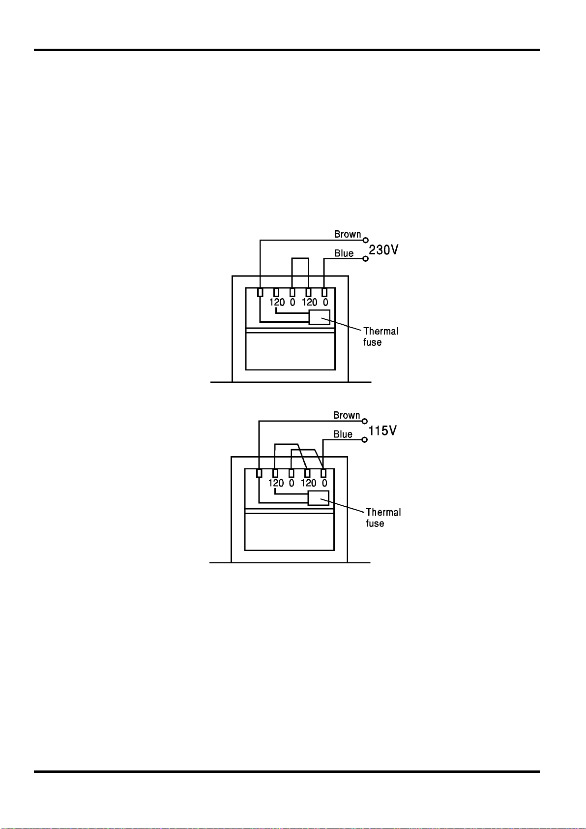
3. Chang e t he transformer connections f ollowing the diag r am s below.
230V Operating - Primaries in series
Installation
115V Operation - Primaries in parallel
4. Reassemble in the reverse order.
5. To comply with safety standard requirem ents t he operating voltage marked on the rear
panel must be changed to clearly show the new voltage setting.
MAINS LEAD
When a three c or e m ains lead with bare ends is provided it should be connected as follows:-
6
Brown - Mains live
Blue - Mains neutral
Green/Yellow - Earth
WARNING! THIS INSTRUMENT MUST BE EARTHED
Any interruption of the mains earth conduct or inside or outside t he inst r um ent will make the
instrument dangerous. Int entional interruption is prohibited.
Page 8
POWER
The ON/OFF switch is on the rear panel of the instr um ent.
FREQUENCY SELECTION
Frequency range is selected by an eight position multiplier switch with fine adjustment by
calibrated vernier.
SYMMETRY
A slide switch selects the symmetry control which varies the duty cycle 1:6 to 6:1 to produce
sawtooth and variable pulse-width waveforms.
Note: The symmetry of the Aux Output does not vary when Sine or Triangle are selected
because the Aux Output is generated by a zero crossing comparator.
FUNCTION SELECTION
The output waveform shape is selected by a four position switch to give sine, square, triangle
and DC. A DC level only is useful as it permits input threshold testing of a circuit without having
to connect up an external supply.
Operation
MAIN OUTPUT
The amplitude of the 50 Ω MAIN output is controlled by the 3-position ATTENUA TOR switches
and AMPLITUDE control. Maximum output is 20 volts peak-to-peak from 50 Ω and 10 volts peakto-peak when terminated with a 50 Ω load.
The AMPLITUDE control has greater than 26dB range and used in conjunction with the
ATTENTUATORS a range of 0dB to -66dB can be achieved. This provides a range of 20V peakto-peak down to 10mV peak-to-peak, or 10V peak -to-peak down to 5mV peak-to-peak into 50 Ω.
Greater attenuation can be achieved by using standard 50 Ω BNC attenuators. To maintain
waveform integrity only 50 Ω cable should be used and the receiving end should be terminat ed
with a 50 Ω load. The 50 Ω MAIN output will withstand a short circuit for a period of 2 minutes at
maximum output and greater periods at lower output levels.
Do not apply external voltages to this output.
DC OFFSET
The DC OFFSET control has a range of ± 10 volts fr om 50 Ω in all output modes; the control has
a centre detent for 0 volts. DC offset plus s ig nal peak is limited to ± 10V (± 5V into 50 Ω). DC
offset plus waveform is attenuated proportionally in the -20dB and -40dB positions.
AUX OUTPUT
The AUX output provides a fixed TTL pulse output at the same frequency and phase as the
50 Ω MAIN output and is capable of driving 4 standard TTL loads.
SWEEP INPUT
The generator fr equency can be swept, DC programmed or modulated by a suitable control
voltage applied to the SWEEP IN socket. The instrum ent s um s the SWEEP IN voltage with the
internal control voltage derived from the FREQUENCY vernier to determine the operating
frequency. A positive voltage increases the frequency; for f r equency control with positive-going
DC inputs the vernier should therefore be set to the lower fr equency limit of the range to be
swept. For example, a 0V to +2V signal will sweep the generator 1 decade up from r ange
minimum, set by the vernier, to range maximum.
7
Page 9

Similarly, a negative voltage decreases the frequency and for neg ative-going DC inputs the
vernier should be set to the upper freq uency limit of the range to be swept. For example, a 0V to
-2V signal will sweep the generator 1 decade down from range maximum, set by the vernier, to
range minimum.
To use a sweep signal which is symmetrical about g r ound, the vernier should be set to give a
frequency at approximately the centre of the band to be swept.
Do not apply external voltages exceeding ±10V.
The Manufacturers or their ag ents overseas will provide a repair service for any unit developing a
fault. Where owners wish to undertake their own maintenance work, this should only be done by
skilled personnel in conjunction with the service manual which may be purchased directly from
the Manufacturers or their agents overseas.
Maintenance
Cleaning
If the instrument r equires cleaning use a cloth that is only lightly dampened with water or a mild
detergent.
WARNING! TO AVOI D EL ECTRI C SHOCK, OR DAMAGE TO THE INSTRUMENT, NEVER
ALLOW WATER TO GET INSIDE THE CASE. TO AVOID DAMAGE TO THE CASE NEVER
CLEAN WITH SOLVENTS.
8
Page 10

risque d'endommager l'appareil.
l
Sécurité
Cet instrument est de Classe de sécurité 1 suivant la classif icat ion I EC et il a été c onst ruit pour
satisfaire aux impératifs EN61010-1 ( I m pér atifs de sécurité pour le matériel électrique en vue de
mesure, commande et utilisation en laboratoir e) . Il s'agit d'un instrument d'installation Catégorie
II devant être exploité depuis une alimentation monophasée habituelle.
Cet instrument a été soumis à des essais conformément à EN61010-1 et il a été fourni en tout
état de sécurité. Ce manuel d'instructions contient des informations et avertissements qui doivent
être suivis par l'utilisateur afin d'assurer un fonctionnement de toute sécurité et de conserver
l'instrument dans un état de bonne sécurité.
Cet instrument a été conçu pour êtr e ut ilisé en inter ne dans un environnement de pollut ion
Degré 2, plage de températur es 5°C à 40°C, 20% - 80% HR (sans condensation). Il peut être
soumis de temps à autre à des températures c om pr ises entre +5°C et –10°C sans dégradation
de sa sécurité. Ne pas l'utiliser lorsqu'il y a de la condensation.
Toute utilisation de cet instrument de manière non spécifiée par ces instructions risque d'affecter
la protection de sécurité conférée. Ne pas utiliser l'instrument à l'extérieur des tensions
d'alimentation nominales ou de la gamme des conditions ambiantes spécifiées.
AVERTISSEMENT! CET INSTRUMENT DOIT ETRE RELIE A LA TERRE
Toute interr upt ion du conduc t eur de terre secteur à l'intérieur ou à l'extérieur de l'instr um ent
rendra l'instrument dangereux. I l est absolument interdit d'effectuer une int er r uption à dessein.
Ne pas utiliser de cordon de prolongation sans conducteur de protect ion, car c eci annulerait sa
capacité de protection.
Lorsque l'instrument est r elié à son alimentation, il est poss ible q ue les bor nes s oient s ous
tension et par suite, l'ouverture des couvercles ou la dépose de pièces (à l'exception de celles
auxquelles on peut accéder manuellement) risque de met t re à découvert des pièces sous
tension. Il faut débrancher t out e s our ce de tension éventuelle de l'appareil avant de l'ouvrir pour
effectuer des réglages, r emplacements, travaux d'entretien ou de réparations.
Eviter dans la mesure du possible d'effectuer des rég lages, travaux de réparations ou d'entretien
lorsque l'instrument ouvert est branché à une source d'alimentation, mais si c'est absolument
nécessaire, seul un technicien compétent au courant des r isques encourus doit effectuer ce
genre de travaux.
S'il est évident que l'instrument est défectueux, qu'il a été soumis à des dégâts mécaniques, à
une humidité excessive ou à une corrosion chimique, la protection de sécurité ser a am oindr ie et
il faut retirer l'appareil, afin q u'il ne soit pas utilisé, et le renvoyer en vue de vérifications et de
réparations.
Uniquement remplacer les fusibles par des fusibles d'intensité nominale requise et de type
spécifié. Il est interdit d'ut iliser des fusibles bricolés et de court-circuiter des por t e-fusibles.
Eviter de mouiller l'instrument lors de son nettoyage.
Les symboles suivants se trouvent sur l'instrument, ainsi que dans ce m anuel.
Attention - se référ er à la docum entation ci-jointe; tout fonctionnement incor r ec t
alimentation secteur ON (allumee)
alimentation secteur OFF (eteinte)
9
borne reliée à la terre due châssis
courant alternatif (c.a.)
Page 11

TENSION D’UTILISATION SECTEUR
La tension de fonctionnement de l'instrument est indiquée sur le panneau arrière. S'il convient de
changer la tension de fonctionnement de 230 V à 115 V ou réciproquement, procéder de la manière
suivante:
1. Débrancher l'instrument de toutes les sources de tension.
2. Enlever les 4 vis qui retiennent ensemble les moitiés supérieure et inférieure du boîtier et
retirer la moitié supérieure du boîtier.
3. Changer les connexions du transformateur selon les schémas ci-dessous.
230V Operating - Primaries in series
Installation
115V Operation - Primaries in parallel
4. Remonter en effectuant ces opérations dans l'ordre inverse.
5. Pour satisfaire aux impératifs de sécurité standard, changer la tension de fonctionnement
marquée sur le panneau arrière pour indiquer clairement le nouveau réglage de tension.
CÂBLE SECTEUR
Relier de la manière suivante tout câble secteur à trois conducteurs à fils nus:
Marron - Secteur sous tension
10
Bleu - Secteur neutre
Vert/Jaune - Terre
AVERTISSEMENT! CET INSTRUMENT DOIT ETRE RELIE A LA TERRE
Toute interruption du conducteur de terre secteur à l'intérieur ou à l'extérieur de l'instrument rendra
l'instrument dangereux. Il est absolument interdit d'effectuer une interr upt ion à dessein.
Page 12

ALIMENTATION
L'interrupteur se trouve sur le panneau arrière de l'instrument.
SELECTION DE FREQUENCE
Utiliser un commutateur multiplicateur à huit positions avec ajust em ent de pr éc ision par vernier
calibré pour sélectionner la gamme de fréquence.
SYMETRIE
Un commutateur coulissant sélectionne la commande de symétrie q ui fait varier le rapport
cyclique de 1:6 à 6:1 pour produire des formes d' onde en dents de sc ie et de lar geur d'impulsion
variable.
Nota: Il ne se produit pas de variation de sortie auxiliaire en cas de sélection de signal
sinusoïdal ou en dents de scie, étant donné que la sortie auxiliaire est générée par un
comparateur de croisement de zéro.
SELECTION DE FONCTION
La forme d'onde de sortie est s élect ionnée par un comm utat eur à quatre positions qui donne un
signal sinusoïdal, carré, en dents de scie et c.c. Seul le niveau c.c. est utile, car il perm et
d'effectuer des essais de seuil d'entrée de cir cuit , s ans qu'il soit nécessaire de relier une
alimentation externe.
Fonctionnement
SORTIE PRINCIPALE
L'amplitude de la sortie PRINCIPALE de 50 Ω est commandée par les commutateurs
d'ATTENUATEUR à 3 positions et par la commande d'AMPLITUDE. La sortie maximale est de
20 V crête-crête de 50 Ω et de 10 V cr ête-crête en cas de terminaison par une charge de 50 Ω.
La commande d'AMPLITUDE a une gamme supérieure à 26 dB et lorsqu'elle est utilisée
conjointement avec les ATTENUATEURS, il est possible d'obtenir une gamme de 0 dB à -66 dB.
Ceci confère une gamme de 20 V crête-crête pouvant descendre jusqu'à 10 mV crête-crête, ou
10 V crête-crête jusqu'à 5 mV crête-crête dans une charge de 50 Ω.
Il est possible d'obtenir une atténuation supérieure en ut ilisant des at t énuateurs de 50 Ω BNC
standard. Utiliser uniquement des câbles de 50 Ω et terminer l'extrémité de réception par une
charge de 50 Ohm pour maintenir l'intégrité de la forme d'onde. La sort ie PRINCIPALE de 50 Ω
pourra résister à un court-circuit pendant une durée de 2 minutes à une sortie maximale et
pendant de plus grandes durées à des niveaux de sortie inférieurs.
Ne pas appliquer de tensions externes à cette sortie.
DECALAGE C.C.
La commande DECALAGE C.C. a une gamme de ± 10 V de 50 Ω dans tous les modes de sortie;
la commande a une détente centrale de 0 V. Le décalage c.c. plus la crête de signal sont limités
à ± 10 V (± 5 V dans 50 Ω). Le décalage c. c . plus la forme d'onde sont atténués
proportionnellement aux positions -20 dB et -40 dB.
SORTIE AUXILIA IRE
La sortie AUX fournit une impulsion de sortie TTL fixe aux mêmes fréquence et phase que la
sortie PRINCIPALE de 50 Ω et elle est en mesure de piloter 4 c har ges TTL standard.
11
Page 13

ENTREE DE BALAYAGE
La fréquence du générateur peut être balayée, qu'il s'agisse d'un signal c. c. programmé ou
modulé par une tension de commande appropriée à la prise d'entrée de balayage (SWEEP IN).
L'instrument ajoute la tension d'ENT REE DE BALAYAGE à la tension de commande interne
dérivée du vernier de fréquence pour déterminer la fréquence opérationnelle. Une tension
positive augmente la fréquence. I l faut donc régler le vernier à la limite de fréquenc e inférieure
de la gamme à balayer dans le cas de commande de fréq uenc e avec entr ées c . c. positives.
Ainsi, par exemple, un signal de 0 V à +2 V augmentera le balayage du générateur d'une décade
depuis la gamme minimale réglée par le vernier, jusqu'au maximum de la gamme.
De manière similaire, une tension négative réduit la fréquence et il faut régler le vernier à la limite
de fréquence supérieure de la gam m e à balayer dans le cas d' ent r ées c. c . négatives. Ainsi, par
exemple, un signal de 0 V à -2 V réduira le balayage du générateur d'une décade depuis la
gamme maximale réglée par le vernier, jusqu'au minimum de la gamme.
Régler le vernier pour obtenir une fréquence environ au cent r e de la bande à balayer, afin de
pouvoir utiliser un signal de balayage symétrique par rapport à la terre.
Ne pas appliquer de tensions externes supérieures à ± 10 V.
Entretien
Le Constructeur ou ses agents à l'étranger répareront tout bloc qui tombe en panne. Si le
propriétaire de l'appareil décide d'effectuer lui-même la maintenanc e, c eci doit uniquement être
effectué par un personnel spécialisé qui doit se référ er au m anuel d’entretien que l'on peut se
procurer directement auprès du Constr uc t eur ou de s es agents à l'étranger.
Nettoyage
S'il faut nettoyer l’instrument, utiliser un chiffon légèrement imbibé d'eau ou d'un détergent doux.
AVERTISSEMENT! EMPECHER TOUTE INTRODUCTION D'EAU DANS LE BOITIER AFIN
D'EVITER TOUT CHOC ELECTRIQUE ET DEGATS A L’INSTRUMENT. NE JAMAIS UTILISER
DE DISSOLVANTS POUR NETTOYER L’INSTRUMENT, AFIN D'EVITER D'ENDOMMAGER LE
BOITIER.
12
Page 14

kann Schaden am Gerät verursachen!
Sicherheit
Dieses Gerät wurde nach der Sicherheitsklasse (Schutzart) I der IEC-Klassifikation und gemäß
den europäischen Vorschriften EN61010-1 (Sicherheitsvorschriften für Elektrische Meß-, Steuer,
Regel- und Laboranlagen) entwickelt. Es handelt sich um ein G er ät der Installationskategorie II,
das für den Betrieb von einer normalen einphasigen Versorgung vorgesehen ist.
Das Gerät wurde gemäß den Vorschriften EN61010-1 geprüft und wurde in sicherem Zustand
geliefert. Die vorliegende Anleitung enthält vom Benutzer zu beachtende Informationen und
Warnungen, die den sicheren Betrieb und den sicheren Zustand des G er ätes gewährleisten.
Dieses Gerät ist für den Betrieb in I nnenr äum en der Um gebungsklass 2 , für einen
Temperatur bereich von 5° C bis 40° C und 20 - 80 % relative Feuchtigkeit (nicht kondensier end)
vorgesehen. Gelegentlich kann es Temperaturen zwischen +5° und –10°C ausgesetzt sein, ohne
daß seine Sicherheit dadurch beeinträchtigt wird. Betreiben Sie das Gerät jedoch auf keinen Fall,
solange Kondensation vorhanden ist.
Ein Einsatz dieses Geräts in einer Weise, die für diese Anlage nicht vorgesehen ist, kann die
vorgesehene Sicherheit beeinträchtigen. Auf keinen Fall das Gerät außerhalb der angegebenen
Nennversorgungsspannungen oder Umgebungs beding ungen betreiben.
WARNUNG! - DIESES GERÄT MUSS GEERDET WERDEN!
Jede Unterbrechung des Netzschutzleiters innerhalb oder außerhalb des Ger äts m acht das
Gerät gefährlich. Eine absichtliche Unterbrechung ist verboten. Die Schutzwirkung darf dur c h
Verwendung eines Verlängerungskabels ohne Schutzleiter nicht aufgehoben werden.
Ist das Gerät an die elektrische Versorgung angeschlossen, so können die Klemmen unter
Spannung stehen, was bedeutet, daß beim Entfernen von Verkleidungs- oder sonstigen T eil en
(mit Ausnahme der Teile, zu denen Zugang mit der Hand möglich ist) höchstwahrscheinlich
spannungsführende Teile bloßgelegt weden. Vor jeglichem Öffnen des Geräts zu Nachstell-,
Auswechsel-, Wartungs- oder Reparaturzwecken, G erät stets von sämtlichen Spannungsquellen
abklemmen.
Jegliche Nachstellung, Wartung und Reparatur am geöffneten, unter Spannung stehenden
Gerät, ist nach Möglichkeit zu vermeiden. Falls unvermeidlich, sollten solche Arbeiten nur von
qualifiziertem Personal ausgeführ t werden, das sich der Gefahren bewußt ist.
Ist das Gerät eindeutig fehlberbehaftet, bzw. wurde es mechanisch beschädigt, übermäßiger
Feuchtigkeit oder chemischer Korr os ion ausgesetzt, so können die Schutzeinrichtungen
beeinträchtigt sein, weshalb das Gerät aus dem Verkehr zurückgezogen und zur Überprüfung
und Reparatur eingesandt werden sollte.
Sicherstellen, daß nur Sicherungen der vorgeschriebenen Stromstärke und des vorg es ehenen
Typs als Ersatz verwendet werden. Provisorische “Sicherungen” und der Kurzschluß von
Sicherungshaltern ist verboten.
Beim Reinigen darauf achten, daß das Gerät nicht naß wird.
Am Gerät werden folgende Symbole verwendet:
Vorsicht! Bitte beachten Sie die beigefügten Unterlagen. Falsche Bedienung
l
13
Netz ON (ein)
Netz OFF (aus)
Masse
Wechselstrom
Page 15

NETZBETRIEBSSPANNUNG
Die Betriebsspannung des Gerätes ist auf der Geräterückwand angegeben. Falls eine Änderung
der Betriebsspannung von 230 V auf 115 V erforderlich ist, ist wie folgt vorzugehen:
1. G er ät von sämtlichen Spannungsquellen trennen.
2. Die vier Schrauben entf er nen m it denen die obere und untere Gehäusehälfte
zusammengehalten wird; dann obere Gehäusehälfte abheben.
3. Die Transformatoranschlüsse entspr ec hend den nachstehenden Diagrammen ändern.
230V Betriebsspannung - Primärwicklung in Reihe geschaltet
Installation
115V Betriebsspannung - Primärwicklung parallelgeschaltet
4. I n um gekehrter Reihenfolge wieder zusammenbauen.
5. Zur Einhaltung der Sicherheitsvorschriften muß die auf der Geräterückwand angezeigte
Betriebsspannung entsprechend der neuen Einstellung geändert werden.
NETZKABEL
Steht nur ein Netzkabel ohne Stecker zur Verfügung, so ist es wie folgt anzuschließen:
Braun - Stromführender leiter
Blau - Nulleiter
Grün/Gelb - Schutzleiter
WARNUNG! DIESES GERÄT MUSS GEERDET WERDEN!
Jede Unterbrechung des Netzschutzleiters innerhalb oder außerhalb des Ger äts m acht das
Gerät gefährlich. Eine absichtliche Unt erbrechung ist verboten.
14
Page 16

EIN/AUS
Der EIN/AUS-Schalter befindet sich auf der Rückwand des Geräts.
FREQUENZWAHL
Der Frequenzbereich wird mit Hilfe eines Multiplikationsschalters mit acht Schaltstellungen
einschließlich Feineinstellung gewählt.
SYMMETRIE
Mit einem Schiebeschalter erfolgt die Symmetriereg ulierung, welche zur Erzeugung von
Sägezahnwellenformen und Wellenformen m it veränderlicher Pulsbreit e das Einschaltverhältnis
zwischen 1 : 6 und 6 : 1 verändern kann.
Hinweis: Die Symmetrie des Hilfsa usgangs (Aux Output) ändert sich nicht, wenn Sinus- oder
Dreieckwellenform gewählt werden, da der Hilfsausgang von einem Komparator mit
Nulldurchgang generiert wird.
FUNKTIONSWAHL
Die Ausgangswellenform wird mittels eines Schalter s m it vier Schaltstellungen gewählt, der
Sinus-, Rechteck- und Dreieckwellenform en s owie Gleichspannung bewirkt. Gleichspannung ist
deshalb nützlich, weil sie die Eingangschwellenprüfung eines Stromkreises ermöglicht, ohne daß
ein Anschluß an eine externe Versorgung erforderlich wird.
Betrieb
HAUPTAUSGANG
Die Amplitude des 50 Ω HAUPT-Ausgangs wird von den DÄMPFUNGS-Schaltern mit 3
Schaltstellungen und der AMPLITUDEN-Regelung ger egelt. Der maximale Ausgang beträgt 20
Volt Spitze zu Spitze bei 50 Ω und 10 Volt Spitze zu Spitze, wenn ein Abschluß mit einer Last von
50 Ω erfolgt.
Die AMPLITUDEN-Regelung besitzt einen Bereich von über 26 dB und wird in Verbindung mit
den DÄMPFUNGSGLIEDERN eingesetzt. Ein Regelbereich von 0 dB bis zu -66 dB ist möglich.
Dies ermöglicht einen Bereich von 20 Volt Spitze zu Spitze bis zu 10 mV Spitze zu Spitze, oder
10 V Spitze zu Spitze bis zu 5 mV Spitze zu Spitze nach 50 Ω.
Eine größere Dämpfung kann mit s tandardm äßigen 50 Ω BNC-Dämpfungsgliedern erreicht
werden. Um die Wellenform auf r ec ht zu erhalten, sollten nur 50 Ω-Kabel verwendet werden. Das
Empfangsende sollte dabei mit einem 50 Ω Widerstand abgeschlossen werden. Der 50 Ω
HAUPT-Ausgang hält einem Kurzschluß von 2 Minuten bei maximalem Ausg ang stand und
entsprechend längere Zeit bei niedrigeren Ausgangspegeln.
Keine externen Spannungen an diesen Ausgang anlegen!
DC OFFSET
Die DC OFFSET - Reguliereinrichtung besitzt einen Bereich von ± 10 V ab 50 Ω in allen
Ausgangsmodi. Die Regliereinrichtung ist m it einer Einr ast vorr icht ung für 0 Volt versehen. DC
Offset plus Signalspitze ist auf ± 10V ( ± 5V nach 50 Ω) beschränkt. DC Offs et plus Wellenform
wird in den Stellungen -20 dB und -40 dB proportional gedämpft.
HILFSAUSGANG A UX OUTPUT
Der Hilfsausgang AUX liefert einen fixierten TTL - Impulsausgang derselben Freq uenz und
Phase wie der 50 Ω HAUPT-Ausgang und ist in der Lage 4 standardmäßige TTL-Lasten zu
treiben.
15
Page 17

ABLENKUNGSEINGANG
Die Generatorfrequenz kann abgelenkt, DC-programmier t oder m it tels einer geeigneten
Steuerspannung moduliert werden, die an den ABLENKUNGS-Eingang angelegt wird. Das Gerät
summiert die Spannung des ABLENKUNGSEINGANGS mit der inneren Steuerspannung, die von
der FREQUENZ-Feineinstellung abgeleitet wird, um die Betr iebsfrequenz zu erhalten. Eine
positive Spannung erhöht die Frequenz. Bei Frequenzsteuer ung mit positivem Verlauf der DCEingänge sollte die Feineinstellung daher auf die untere Fr equenzgrenze des Bereichs gestellt
werden um abgelenkt zu werden.Ein 0 Volt bis + 2 Volt- Signal lenkt den Generator um 1 Dekade
vom Minimum des Feineinstellungsbereichs nach oben bis zum Maximum des Bereichs.
Auf ähnliche Weise vermindert eine negat ive Spannung die Frequenz, weshalb bei DCEingängen mit negativem Verlauf die Feineinstellung auf die obere Frequenzgrenze des Bereichs
zu stellen ist. So lenkt z. B. ein 0 Volt bis -2 Volt-Signal den Generator um 1 Dekade vom
Maximum des Feineinstellbereichs nach unten bis zum Minimum des Bereichs ab.
Um ein erdesymmetrisches Ablenksignal zu benutzen, sollte die Feineinstellung etwa auf die
Frequenz in der Mitte des zu durchzulaufenden Bereichs gestellt werden.
Keine externen Spannungen anlegen, die ±10V überschreiten.
Die Hersteller bzw. deren Vertretungen im Ausland bieten die Reparatur von Geräten an, bei
denen eine Störung aufgetreten ist. W enn der Eig ent üm er die Wartungsarbeiten selbst
durchführen möchte, hat er dafür Sorge zu tragen, daß diese Arbeiten ausschließlich von
entsprechend qualifiziertem Personal und gemäß Wartungshandbuch ausgeführt werden, das
direkt von den Herstellern oder deren Vertretungen im Ausland bezogen werden kann.
Reinigung
Falls das Gerät der Reinigung bedarf, einen mit Wasser oder einem milden Detergens
angefeuchteten Lappen benutzen.
WARNUNG! ZUR VERMEIDUNG EINES ELEKTRISCHEN SCHLAGS BZW. DER
BESCHÄDIGUNG DES GERÄTES, DAFÜR SORGEN, DASS KEIN WASSER INS GEHÄUSE
EINDRINGT. UM SCHADEN AM GEHÄUSE ZU VERMEIDEN, KEINE LÖSUNGSMITTEL ZUR
REINIGUNG VERWENDEN!
Wartung
16
Page 18

strumento.
Sicurezza
Questo strumento appartiene alla Categoria di Sicurezza 1 secondo la classifica I EC ed è stato
progettato in modo da soddisfare i crit er i EN61010-1 (requisiti di Sicurezza per Apparecchiature
di misura, controllo e per uso in laboratorio). E’ uno strumento di Categor ia I I di installazione e
inteso per funzionamento con un’alimentazione normale monofase.
Questo strumento ha superato le pr ove previste da EN61010-1 e viene fornito in uno stato di
sicurezza normale. Questo manuale contiene informazioni e avvertenze che devono essere
seguite per assicurarsi di un’operazione sicura e mantenere lo str um ento in condizioni di
sicurezza.
Questo strumento è prog et tat o per uso all’interno e in un am bient e d’inq uinamento Grado 2,
entro la gamma di temperatur a da 5° C a 40C°, con um idità relativa (non condensante) di
20% - 80%. Può occasionalmente essere assoggettato a temperature fra +5°C e –10°C senza
comprometterne la sicurezza. Non usare in presenza di condensazione.
L’uso dello strumento in maniera non conforme a quanto specificato in quest e ist ruzioni potrebbe
pregiudicare la protezione di cui è dotato. Non usare lo strumento per misurare tensioni al di
sopra dei valori nominali o in condizioni ambientali al di fuori di quelle specificate.
ATTENZIONE! QUESTO STRUMENTO DEVE ESSERE COLLEGATO A TERRA
Una qualsiasi interruzione sia interna che esterna del collegamento a ter r a lo rende pericoloso.
E’ proibito interrompere questo collegamento deliberatamente. La protezione non deve essere
negata attraverso l’uso di un cavo di estensione privo del filo di collegamento a terra.
Quando lo strumento è alimentato, alcuni morsetti sono sotto tensione e l’apertura dei coperchi o
la rimozione di parti (eccetto quei componenti accessibili senza l’uso di attrezzi) può lasciare
scoperti dei morsetti sotto tens ione. L’apparechiatura deve essere staccata da tutte le sorgenti di
tensione prima di aprirla per regolazioni, manutenzione o riparazioni.
E’ consigliabile evitare, per quanto possibile, qualsiasi operazione di regolazione e di riparazione
dello strumento sotto tensione e, q ualora fosse inevitabile, dette operazioni devono essere
eseguite da una persona specializzata in materia, che sia pienemente conscia del pericolo
presente.
Quando sia chiaro che lo strumento è difettoso, o che ha subito un danno meccanico, un
eccesso di umidità, o corrosione a mezzo di agenti chimici, la sicurezza potrebbe essere stata
compromessa e lo strumento deve essere ritir at o dall’uso e rim andat o indietro per le prove e le
riparazioni del caso.
Assicurarsi di usare solo fusibili della portata giusta e del tipo corretto durant e eventuali
sostituzioni. Sono proibiti sia l’uso di fusibili improvvisati che il corto circuito deliberato dei
portavalvole.
Non bagnare lo strumento quando si pulisce.
Sullo strumento e in questo manuale si fa uso dei seguenti simboli.
Attenzione - vedere i documenti allegati. L’uso errato può danneggiare lo
17
l
alimentazione ON (accesa)
alimentazione OFF (spenta)
morsetto collegato a terr a
Corrente Alternata
Page 19

TENSIONE D’ESERCIZIO
La tensione d’esercizio è indicata sul pannello posteriore. Se occorre cambiare tale tensione da
230V a 115V, o viceversa, osservare il seguente procedimento:
1. Scollegare lo strumento da tutte le fonti di tens ione.
2. Rimuovere le 4 viti che teng ono unite le m et à s uper ior e e inferiore dell’involucro e
sollevare la metà superiore.
3. Aiter ar e le conness ioni del tr asformatore seguendo gli schemi sotior ipor tati.
Uso a 230V - Primari in serie
Installazione
Uso a 115V - Primari in parallelo
4. Rimontare in ordine inverso.
5. Per r ispettare le norme di sicurezza, la tensione di funzionamento mostrata sul pannello
posteriore deve essere modificata in modo da indicare chiaramente la nuova
impostazione di tensione.
CAVO D’ALIMENTAZIONE
Quando viene fornito un cavo a tre fili con le estremità nude, collegare come segue:
18
Marrone - Linea
Blu - Neutro
Verde/Giallo - Terra
ATTENZIONE! QUESTO STRUMENTO DEVE ESSERE COLLEGATO A TERRA
Una qualsiasi interruzione sia interna che esterna del collegamento a ter r a lo r ende per icoloso.
E’ proibito interrompere questo collegamento deliberatamente.
Page 20

Funzionamento
ALIMENTAZIONE
lL’interruttore di alimentazione si trova sul pannello posteriore dello strumento.
SELEZIONE DELLA FREQUENZA
La gamma di frequenza si seleziona mediante l’interrutt ore moltiplicatore a otto posizioni e la
regolazione fine si fa a mezzo del verniero calibrato.
SIMMETRIA
Un interruttore scorrevole seleziona il controllo di simmetria che varia il ciclo da 1:6 a 6:1 per
produrre forme d’onda a dente di seg a e a impulso variabile.
Nota: La simmetria dell’uscita ausiliaria non cambia quando si seleziona la forma sinusoidale
o a triangolo perchè l’uscita ausiliaria viene generata da un comparatore incrociato a zero.
SELEZIONE DELLA FUNZIONE
La forma d’onda in uscita viene selezionata mediante un interruttore a quatt r o posizioni per
dare, rispettivamente, la forma sinusoidale, quadrata, triangolare e c.c. Un livello di c.c.
soltanto è utile perchè permette ldi provare il valore di soglia di un circuito senza collegare
un’alimentazione esterna.
USCITA PRINCIPALE
L’ampiezza dell’uscita principale a 50 Ω è controllata dagli interruttori AT TENUATORI A 3
posizioni e dal controllo d’ampiezza.. L’uscita massima è di 20 V. picco-picco da 50 Ω e 10 V.
picco-picco, quando termina con un carico di 50 Ω.
Il controllo dell’AMPIEZZA ha un’escursione di oltre 26 dB e, quando si usa assieme con gli
attenuatori, si può ottenere un’escursione da 0 a 66 dB. Q uesto offre una gamma di 20 V
picco-picco fino a 10 mV. picco-picco, oppure 10 V picco-picco fino a 5 mV. picco-picco con un
carico di 50 Ω.
Si può ottenere un’attenuazione maggiore mediante l’uso di att enuat or i nor m ali da 50 Ω. Per
mantenere l’integrità della form a d’onda si dovrà usare solo un cavo da 50 Ω e con l’estremità
collegata a un carico di 50 Ω. L’uscita PRINCIPALE a 50 Ω può sopportar e un cor to circuito per
un periodo di 2 minuti con il livello d’uscita massimo o per periodi più lunghi con livelli d’uscita
minori.
Non applicare tensioni esterne a questa uscita
DEVIAZIONE C.C.
Il controllo di DEVIAZIONE di C.C. ha un’escursione di ± 10 V. da 50 Ω in tutte le modalità; il
controllo ha un fermo centrale per 0 V. La deviazione c.c. pù il segnale di picco è limitata a ±
10 V. ( ± 5 V con un carico di 50 Ω). La deviazione c.c. più la forma d’onda viene attenuata
proporzionalmente nelle posizioni di -20dB e -40dB.
USCIT A A USILIA RIA
L’USCITA ausiliaria fornisce un impulso TTL fisso alla stessa f r equenza e della stessa fase
dell’uscita PRINCIPALE a 50 Ω ed è capace di controllare 4 carichi TTL normali.
19
Page 21

SCANSIONE D’ENTRATA
La frequenza del generatore può eser e a s cans ione, pr ogrammata a c.c. o modulata mediante
un controllo adatto applicato alla presa ENTRATA SCANSIONE (SWEEP IN). Lo strumento
addiziona la tensione di SCANSIONE in entrata con la tensione di controllo interna derivata dal
verniero della FREQUENZA per determinare la frequenza d’operazione. Una tensione positiva
aumenta la frequenza; per il controllo della frequenza con entrate positive in c.c. il verniero
dovrà perciò essere impostato sul limite inferiore della f requenza della gamma che la scansione
deve coprire. Per esempio, un segnale da 0 V a +2 V. produce nel generatore una scansione
che va da 1 decade al di sopra del minimo della gamma, impostata mediante il verniero, al
massimo della gamma.
In modo simile, una tensione negativa abbassa la frequenza e per entrate c.c. negative il
verniero dovrebbe essere impostato verso il limite superiore della gamma di frequenza da
coprire. Per esempio, un segnale che va da 0 V. a -2 V. produce nel generatore una scansione
che va da 1 decade al di sotto del massimo della gamma, impostato mediante il verniero, al
minimo della gamma.
Per ottenere un segnale di scansione che sia simmetrico r ispet to al potenziale di terra, il
verniero dovrà essere impostato in modo da dare una frequenza approssim at ivamente al centro
della gamma da coprire con la scansione.
Non applicare tensioni ester ne in eccess o di ± 10 V.
Pulizia
Manutenzione
I Produttori o i loro agenti all’estero faranno le riparazioni necessarie in caso di guasto. Qualora
l’utente desiderasse eseguire il lavoro di manutenzione, tale lavoro deve essere fatto solo da
personale qualificato e usando il manuale di servizio che può essere acquistato direttamente dai
Produttori o dai loro agenti all’estero.
Se si deve pulire lo strumento, usare uno strofinaccio appena bagnato con acqua o con un
detergente ad azione dolce.
ATTENZIONE! PER EVITARE LA SCO SSA ELETTRICA ED EVENTUALI DANNI AL
STRUMENTO, NON PERMETTERE MAI ALL’ACQUA DI ENTRARE ALL’INTERNO
DELL’ALLOGGIAMENTO. PER EVITARE DANNI ALL’ALLOGGIAMENTO, NON PULIRE MAI
CON SOLVENTI.
20
Page 22

instrumento.
bastidor
(desconectada)
Seguridad
Este es un instrumento de Clase de Seguridad I seg ún la clasificación del IEC y ha sido
diseñado para cumplir con los requisitos del EN61010-1 (Requisitos de Segur idad para Equipos
Eléctricos para la Medición, Control y Uso en Laboratorio). Es un instrumento de Categor ía de
Instalación II propuesto para ser usado con un suministro monofásico normal.
Este instrumento ha sido comprobado según la nor m a EN61010-1 y ha sido suministrado en una
condición segura. El manual de instrucciones contiene infor m ac ión y advertencias que deben
seguirse para asegurar el empleo seguro por el usuar io y para mantener al inst r um ento en una
condición segura.
Este instrumento ha sido diseñado para ser utilizado en el interior en un ambiente de Grado de
Polución 2 a temperaturas de entre 5ºC y 40ºC y una humedad relativa de entre el 20% y el 80%
(sin condensación). De manera ocasional puede someterse a tem per aturas de entre +5ºC y
−10ºC sin que ello afecte a su seguridad. No hay que poner lo en funcionamiento mientras haya
condensación.
El uso de este instrumento en una manera no especif icada por estas inst r ucc iones puede afectar
a la seguridad protectora provista. El instrumento no debe s er ut ilizado fuer a de s u clasificación
de voltaje o de su gama ambiental.
ADVERTENCIA! ESTE INSTRUMENTO DEBE CONECTARSE A TIERRA
Cualquier interrupción del conductor a tierra dentro o fuera del instrumento implicaría que el
instrumento resultara peligroso. Está pr ohibida cualq uier interrupción intencional. La acción
protectora no debe negarse por el uso de una extensión de cable sin conductor pr otector.
Cuando el instrumento está conectado a su suministro es posible que queden sin protección
elementos bajo tensión y la abertura de tapas o el retiro de piezas (salvo las accesibles por la
mano) pueden dejar expuestos a elementos bajo tensión. Si se tuviera q ue efectuar alguna
operación de ajuste, cambio, mantenimient o o r eparación es necesar io desconec tar al
instrumento de todas las fuent es de t ensión.
Todo ajuste, m antenimiento o reparación del instrumento abierto bajo tensión debe ser evitado
en lo posible, pero si fuera ineludible, estos trabajos deben ser r ealizados exclusivamente por un
personal cualificado consciente del riesgo que im plican.
Si el instrumento fuera claramente defectuoso, hubiera sido sometido a un daño mecánico, a
humedad excesiva o a corrosión química, su protección de seguridad puede fallar y el aparato
debe sacarse de uso y devolverse para comprobación y reparación.
Asegurar que sólo se empleen fusibles de la clasif icac ión y tipo especificados para todo
recambio. Está prohibido utilizar fusibles improvisados así como el corto circuito de portafusibles.
El instrumento no debe humedecerse al ser limpiado. Los símbolos a continuación son
empleados en el instrumento y en este manual:-
Advertencia - Remitirse a los documentos adjuntos, el uso incorrecto puede dañar al
21
alimentación principal ON (conectada)
l
alimentación principal OFF
borne conectado a la tierra del
corriente alterna (ca)
Page 23

VOLTAJE DE ALI MENTACIÓN DE LA RED
Se indica el voltaje del instrumento en el panel trasero. Si es necesario cambiar el voltaje de 230V a
115V ó vice-versa, proceder de la siguiente manera:
1. Desconectar el instrumento de toda conexión a la red eléctrica.
2. Quitar los 4 tornillos que mantienen las mitades superior e inferior de la carcasa unidas y
alzar la mitad superior de la carcasa.
3. Cambie las conexiones del transformador, siguierido los diagramas que figuran a
continuacion.
Funcionamiento a 230V - Primarias en serie
Instalación
Funcionamiento a 115V - Primarias en paralelo
4. Vuelva a armar en orden inverso.
5. Para cumplir con los requisitos de la normas de seguridad se debe cambiar el voltaje
señalado en el panel trasero para indicar claramente el nuevo volt aje que se debe usar.
CABLE DE RED
Cuando se suministra un cable de tres conductores con puntas peladas, se deberá conect ar como
sigue:
22
Marrón - Corriente de red
Azul - Neutro de red
Verde/Amarillo - Tierra
ADVERTENCIA! ESTE INSTRUMENTO DEBE CONECTARSE A TIERRA
Cualquier interrupción del conductor a tierra dentro o fuera del instrumento implicaría que el
instrumento resultara peligroso. Está prohibida cualquier interrupción intencional.
Page 24

ALIMENTACION
El conmutador ON/OFF (CONECTADO/DESCONECTADO) está situado en el panel posterior del
instrumento.
SELECTOR DE FRECUENCIA
La gama de frecuencia se selecciona mediante un conm utador m ult iplicador de 8 posiciones
dotado de un ajuste fino por vernier calibrado.
SIMETRIA
Un conmutador deslizante selecciona el control de simetría que cambia el ciclo de servicio de 1:6
a 6:1 para producir ondas sinusoidales serradas y campo de pulso variable.
Nota: La simetría de la salida auxiliar 'Aux Output' no cambia al seleccionar Seno o Triángulo
porque la salida auxiliar se genera por un comparador que cruza el cero.
SELECTOR DE FUNCIONES
La forma de la onda de salida se selecciona mediante un conmutador de cuatro pos iciones q ue
dá ondas en forma sinusoidal, cuadrada, tr iang ular y de CC. Un nivel de CC solo es útil porque
permite ensayar el umbral de un circuito sin tener que conectar se a un suministro de fuerza
externa.
Funcionamiento
SALIDA PRINCIPAL
La amplitud de salida MAIN (PRINCIPAL) está controlada mediante los conmutadores
ATTENUATOR (ATENUADOR) de tres posiciones y el control AMPLITUDE (AMPLITUD). La
salida máxima es de 20 voltios cresta a cresta con 50Ω y de 10 voltios cresta a cresta si se
termina con una carga de 50Ω.
El control AMPLITUDE (AMPLITUD) posse una gama de más de 26dB y al emplearse conjunt o a
los ATTENUATORS (ATENUADORES) se puede obtener una gama de 0dB a -66dB. Est o
proporciona una gama desde 20V cresta a cresta hasta 10mV cresta a cresta, o desde 10V
cresta a cresta hasta 5mV cresta a cresta a 50Ω
Se puede conseguir una mayor atenuación utilizando atenuadores estándard BNC de 50Ω. Para
mantener la integridad de la forma de onda s e debe usar s olamente un cable de 50Ω y el
receptor terminal debe terminarse con una c ar ga de 50Ω. La salida MAIN (PRINCIPAL) de 50Ω
es a prueba de cortocircuitos durante un plazo de 2 minutos a salida máxima y por mayor plazo
a niveles de salida inferiores.
No deben aplicarse voltajes externos a esta salida.
DESVIACION DE CC
El control DC OFFSET (DESVIACION DE CC) tiene una gama de ±10V a partir de 50Ω en
todas las modalidades de salida, este control posee un centro de detent e para 0 voltios. La
desviación de CC más la cresta de señal está limitada a ±10V (±5V a 50Ω). La desviación de CC
más la forma de onda se atenúa propor cionalmente en las posiciones de -20dB y -40dB.
.
SALIDA AUXILIAR
La salida AUX proporciona una salida de pulsos TTL fija a la misma frecuencia y fase que la
salida MAIN de 50Ω y es capaz de excitar a 4 cargas TTL estándard.
23
Page 25

ENTRADA DE BARRIDO
La frecuencia del generador puede barrer se, programarse a CC o modularse mediante un voltaje
de control adecuado aplicado al enchufe SWEEP IN (BARRIDO). El instrumento suma el voltaje
del SWEEP IN (BARRIDO) con un control de voltaje interno derivado del vernier FREQUENCY
(FRECUENCIA) para determinar la frecuencia operacional. Un voltaje positivo aumenta la
frecuencia; para control de fr ecuencias c on ent r adas de CC crecient es se debe r eglar al vernier
al límite inferior de frecuencia de la gama a barr er. Por ejemplo, una señal de 0V a +2V
ocasionará un barrido del generador de e década desde el mínimo de la gama, regala por
vernier, hasta el máximo de la gama.
De igual manera, un voltaje negativo reduce la frecuencia y para entradas de CC en sentido
decreciente se debe regalr al vernier al límite superior de fr ecuenc ia de la g am a a bar r er. Por
ejemplo, una señal de 0V a -2V ocasionará un barrido del generador de 1 década desde el
máximo de la gama, reglada por vernier, hasta el máximo de la gama.
Para usar una señal de barrido que sea simétrica sobre la t ierr a, el vernier debe reglarse a una
frecuencia aproximadamente al centro de la banda a barrer.
No deben aplicarse voltajes externos que superen ±10V.
Los fabricantes o sus agentes en el extranjero ofrecen un servicio de reparación para toda
unidad que desarrolle un defecto. Si los propietarios desearan establecer su propio servicio, esto
sólo debe realizarse por personas cualificadas en conjunto con el manual de servicio que puede
adquirirse directamente del Fabricante o de sus agentes en el extranjero.
Limpieza
Si el instrumento necesita ser limpiada, utilizar un paño brevemente humedecido en agua o en
un detergente suave.
ADVERTENCIA! PARA EVITAR CHOQUES ELECTRICOS O DAÑAR AL INSTRUMENTO,
NUNCA DEJE ENTRAR AGUA AL ENVASE. PARA EVITAR QUE EL ENVASE SEA DAÑADO,
NUNCA LIMPIE CON SO LVENTES.
Mantenimiento
24
Page 26

Ltd
.
)
Thurlby Thandar Instruments
Glebe Road • Huntingdon • Cambridgeshire • PE29 7DR • England (United Kingdom
Telephone: +44 (0)1480 412451 • Fax: +44 (0)1480 450409
International web site:
www
.aimtti.com • UK web site:
www
.aimtti.co.uk
Email: info@aimtti.com
Aim Instruments and Thurlby Thandar Instruments Book Part No. 48591-0500 Issue 7
 Loading...