

Page 1

THURLBY THANDAR INSTRUMENTS
TA320S
32-CHANNEL LOGIC ANALYSER
INSTRUCTION MANUAL
Page 2

Table of Contents
Introduction 1
Section 1 - Specification 2
Section 2 - Safety, Installation and EMC 4
Section 3 - Initial Operation 7
Section 4 - Configuration Menu 10
Section 5 - Trigger Words Menu 14
Section 6 - Trigger Sequence Menu 17
Section 7 - Timing Display 20
Section 8 - List Display 25
Section 9 - Utilities Menu 29
Section 10 - Making an Acquisition 32
Section 11 - ARC Remote Control 33
Introduction
The TA320 is a high performance, very low-cost, portable logic analyser for development, production and
field-service applications. It can capture data across 32 channels (at 25MHz) at up to 100MHz (8
channels) and display it in both Timing and List formats on the built-in supertwist LCD or on a PC screen.
The TA320 features multi-level triggering with event counting and restart. Glitch capture and glitch
triggering are also available with the appropriate input pods. The three external clocks have independent
qualifiers and both data and clock pod inputs can be fixed (TTL) or variable threshold depending on pod
choice.
All functions are accessed through easy to follow soft-key controlled displays. The use of soft-keys
guides the user and minimises the number of keystrokes required to achieve the desired function.
Alternatively the TA320 can be fully remote-controlled via its RS232 serial interface from a PC which
offers an enhanced soft-key orientated user interface and more sophisticated data displays.
An ARC (Addressable RS232 Chain) compatible RS-232 interface is standard, as is non-volatile storage
of data and set-ups (battery-backed CMOS RAM). Disassemblers for popular microprocessors are
optional.
1
Page 3

Section 1 - Specification
SIGNAL INPUTS
Number of Data Channels: 32
Number of Clock Inputs: 3 Independent clock inputs; active edge can be independently selected
for each to be either positive, negative or off.
Number of Clock Qualifiers: 3, 1 for each clock. Selectable to be active high, low or don't care.
Input Characteristics: Determined by the type of pod fitted. All data and clock inputs on the
standard AP01 (25MHz) pod are fixed TTL threshold with an impedance
of typically 100kOhm//10pF. AP03 and AP04 are high speed (100MHz)
TTL threshold data and clock pods respectively, and AP03V/AP04V are
versions with the threshold variable from 2.5V to +7.3V in 100mV steps.
Input impedance for all high speed pods is typically 100kOhm//6pF.
Activity Indicator: Shows whether the channel input is high, low or switching
MEMORY ORGANISATION
Data Memory Size: 32 bits x 2k
Reference Memory Size: 32 bits x 2k
Non-Volatile Memory: Non-volatile storage for 10 acquisitions and 10 set-ups. Data retention
by Lithium cell; typical life 5 years.
EXTERNAL CLOCK
Frequency Range: DC to 25MHz
Minimum Clock Pulse Width: 20ns
Organisation 3 clocks, individually qualified and ORed together.
Set-up and Hold Times: 18ns set-up, 0ns hold for both data and clock qualifiers.
INTERNAL CLOCK
Clock Rate: Selectable 40ns to 100ms (25MHz to 10Hz) in a l:2:4 sequence with all
pods. 10ns (100MHz) with high speed pods in high speed mode.
TRIGGERING
Trigger Sequencer Words: 4 words of up to 32 bits.
Trigger Sequencer Terms: The actual trigger term searched for in a sequencer step each consist
of up to 4 trigger sequencer words ORed together.
Trigger Sequencer Steps: Each of up to 4 sequencer steps consists of a search for the trigger
term specified in that step. Each step has an event count of 1 to 128
occurrences of the trigger term.
Trigger Position: Selectable to be from 0 to 5k clocks before the start, centre or end of
store, in 1k steps.
Trigger Output: TTL level signal at rear panel BNC
GLITCH (Only available when high speed pods are fitted)
Number of Channels: 16 (8 per pod)
Minimum Detectable Pulse: 5ns
Glitch Triggering: A glitch word can be specified which can be ORed with any trigger word
within a trigger term.
2
Page 4

TIMING DISPLAY
Number of Channels: Any 6 channels may be displayed; channels may be repeated.
Channel Labelling: A user-defined name can be given for each group of channels and each
channel will be uniquely numbered within the group.
Number of Samples: A maximum of 1152 samples can be shown in the display window, with
expansions of x2, x4, x8, and x16. The window can be scrolled
throughout the store and a window indicator shows the position of the
window within the store.
Cursors: A movable cursor and a moveable marker, with direct readout of
absolute and relative store positions and the data values at those locations. The marker will default to the trigger location following each
acquisition.
Glitch: Glitches are shown by markers on the appropriate data channels.
Search: A search can be made for any word; the search word may include
glitches on the glitch channels.
LIST DISPLAY
Channel Groups: Up to 32 channels can be grouped together under a single character
label and given the corresponding name defined on the Timing display.
Up to 16 groups can be specified.
Display Format: Binary, Octal, Hex, Decimal or ASCII individually selectable for each
channel group. Each group is listed underneath its label or name.
Cursors: A movable cursor and a fixed marker are provided.
Search & Compare: Differences between data and reference can be shown and a search
made for any word and any difference. Automatic comparisons between
data and reference memories can be performed on a user specified area
of the data and acquisitions stopped on an equality or inequality.
Print Output: Any specified portion of the List display can be printed out via the RS232
interface to a serial or parallel (with PC02 serial-to-parallel converter)
printer.
SYSTEM DATA
Display: 240 x 64 pixel graphic LCD giving 40 characters x 8 lines.
Interface: Addressable RS232 interface, for remote control and data transfer,
complying with the ARC standard.
Audible Warning Signal: Buzzer.
GENERAL
Size: 260(W) x 88(H) x 235(D)mm (10.2 x 3.4 x 9.2").
Weight: 1.9 kg (4.2lb)
Power: 110-120V AC or 220V-240V AC ±10%, 50/60Hz, by rear panel
adjustment. 25VA max. Installation Category II.
Operating Range: +5°C to 40°C, 20-80% RH.
Storage Range:
–20°C to + 60°C.
Environmental: Indoor use at altitudes up to 2000m, Pollution Degree 2
Safety: Complies with EN61010-1.
3
Page 5

Safety
This instrument is Safety Class I according to IEC classification and has been designed to meet
the requirements of EN61010-1 (Safety Requirements for Electrical Equipment for Measurement,
Control and Laboratory Use). It is an Installation Category II instrument intended for operation
from a normal single phase supply.
This instrument has been tested in accordance with EN61010-1 and has been supplied in a safe
condition. This instruction manual contains some information and warnings which have to be
followed by the user to ensure safe operation and to retain the instrument in a safe condition.
This instrument has been designed for indoor use in a Pollution Degree 2 environment in the
temperature range 5°C to 40°C, 20% - 80% RH (non-condensing). It may occasionally be
subjected to temperatures between +5° and -10°C without degradation of its safety. Do not
operate while condensation is present.
Use of this instrument in a manner not specified by these instructions may impair the safety
protection provided. Do not operate the instrument outside its rated supply voltages or
environmental range. In particular excessive moisture may impair safety.
Section 2 - Safety, Installation and EMC
WARNING! THIS INSTRUMENT MUST BE EARTHED
Any interruption of the mains earth conductor inside or outside the instrument will make the
instrument dangerous. Intentional interruption is prohibited. The protective action must not be
negated by the use of an extension cord without a protective conductor.
When the instrument is connected to its supply, terminals may be live and opening the covers or
removal of parts (except those to which access can be gained by hand) is likely to expose live
parts. The apparatus shall be disconnected from all voltage sources before it is opened for any
adjustment, replacement, maintenance or repair.
Any adjustment, maintenance and repair of the opened instrument under voltage shall be avoided
as far as possible and, if inevitable, shall be carried out only by a skilled person who is aware of
the hazard involved.
If the instrument is clearly defective, has been subject to mechanical damage, excessive moisture
or chemical corrosion the safety protection may be impaired and the apparatus should be
withdrawn from use and returned for checking and repair.
Make sure that only fuses with the required rated current and of the specified type are used for
replacement. The use of makeshift fuses and the short-circuiting of fuse holders is prohibited.
This instrument uses a Lithium button cell for non-volatile memory battery back-up; typical life is 5
years. In the event of replacement becoming necessary, replace only with a cell of the correct
type, i.e. 3V Li/Mn0
in accordance with local regulations; do not cut open, incinerate, expose to temperatures above
60°C or attempt to recharge.
Do not wet the instrument when cleaning it and in particular use only a soft dry cloth to clean the
LCD window. The following symbols are used on the instrument and in this manual:-
20mm button cell type 2032. Exhausted cells must be disposed of carefully
2
4
Caution - refer to the accompanying documentation, incorrect operation may
damage the instrument.
alternating current.
Page 6

Mains Operating Voltage
The TA320 is a safety class 1 instrument, installation category II by IEC classification.
Before making connections to the AC line source ensure that the operating voltage of the
instrument is correctly set.
The operating voltage is indicated by the orientation of the fuseholder. When the 230V marking is
upwards the unit is set for operation over the range 198V to 264V. When the 115V marking is
upwards the unit is set for operation over the range 99V to 132V. To change the operating voltage
range, remove the AC line plug, pull out the fuse holder, replace the fuse with one of the appropriate rating (see below) and rotate the fuse holder before pushing it firmly back into place.
Fuse
The correct fuse must be fitted after an operating voltage change. Only a time-lag fuse should be
fitted.
For 230V operation use 125mA 250V time-lag.
For 115V operation use 250mA 250V time-lag.
Make sure that only fuses with the required rated current and of the specified type are used for
replacement. The use of makeshift fuses and the short circuiting of fuse holders is prohibited.
Mains Lead
When a three core mains lead with bare ends is provided this should be connected as follows:
Any interruption of the protective conductor inside or outside the instrument or disconnection of
the protective earth terminal is likely to make the apparatus dangerous. Intentional interruption is
prohibited.
Maintenance
Cleaning
If the instrument requires cleaning use a cloth that is only lightly dampened with water or a mild
detergent. Polish the display with a soft dry cloth.
WARNING! To avoid electric shock, or damage to the instrument, never allow water to get inside
the case. To avoid damage to the case or display never clean with solvents.
BROWN - MAINS LIVE
BLUE - MAINS NEUTRAL
GREEN/YELLOW - EARTH
WARNING! - THIS INSTRUMENT MUST BE EARTHED
5
Page 7

EC Declaration of Conformity
We Thurlby Thandar Instruments Ltd
Glebe Road
Huntingdon
Cambridgeshire PE29 7DR
England
declare that the
TA320S and TA320PC Logic Analysers
i. meets the intent of the Low Voltage Directive 73/23/EEC by conformance with EN61010-1
(1993) Installation Category II.
and
ii. meets the intent of the EMC Directive 89/336/EEC by conforming with the protection
requirements of the U.K. EMC Regulations SI 1992/2372 under the provisions made for
Education and Training Equipment (Regulation 8).
Use of the apparatus outside the classroom, laboratory, study area or similar such place
invalidates conformity with the protection requirements of the Electromagnetic
Compatibility Directive (89/336/EEC) and could lead to prosecution.
The apparatus when operated will not cause electromagnetic disturbance to apparatus
situated outside its immediate electromagnetic environment.
CHRIS WILDING
TECHNICAL DIRECTOR
1 December 1996
6
Page 8
3.1 Introduction
This section describes how the TA320 is made operational and introduces the user to the
keyboard, the menus and the data displays.
3.2 Power
Having checked that the instrument's operating voltage has been correctly set for the local supply
(see section 2), plug the power cord into the rear panel inlet and switch the instrument on using
the POWER switch beside the inlet.
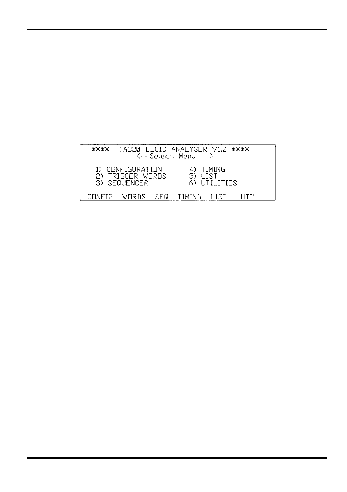
The analyser will 'beep' and the main Select Menu will be displayed below the instrument
designation and firmware revision shown in the top line, see fig. 3.1. The displays accessible via
this menu are described below together with the keyboard operation.
Section 3 - Initial Operation
3.3 Keyboard
The keys on the front panel can be divided into soft-keys, cursor keys and alpha-numeric keys.
Soft-keys
The 6 keys under the LCD each take the function shown immediately above them on the display;
see, for example, fig 3.1. As the cursors move the edit zone around the editable fields of the
display, the functions shown in the boxes change and hence the functions of the keys change; for
this reason they are known as soft-keys.
The six soft-keys of the Select Menu give access to the six menus and data displays through
which the instrument is controlled and results are presented.
The menus and data displays can also be accessed by pressing the appropriate numeric key
shown beside each display name, e.g. 4 for TIMING display. To move from one such menu or
display to another it is always necessary to return to the Select Menu by pressing the MENU key
in the alpha-numeric group, and to then select the new display with the appropriate soft-key.
The operations accessible through each display are presented in detail in sections 4 to 9. Briefly
the features accessed by each key are:
CONFIG CONFIGuration MENU. Selection of the instrument configuration including pod type,
fig 3.1.
clock parameters, and acquisition modes.
WORDS Trigger WORDS MENU. Specification of the channel groups and the trigger words.
SEQ Trigger SEQuence MENU. Specification of the trigger sequence.
TIMING TIMING DISPLAY. Presentation of the acquired data as a waveform display with
magnify, find, etc. features.
LIST LIST DISPLAY. Presentation of the acquired data as a state list display in the
selected bases (binary, octal, hex, decimal, ASCII and microprocessor mnemonics)
with find, compare etc. features.
UTIL UTILities MENU. Primarily for the saving of data and set-ups to non-volatile memory
and for specifying the RS232 inter-face parameters.
7
Page 9

Cursor Keys
The cluster of 4 arrowed cursor keys have 2 basic modes of operation, i.e. moving the edit zone
around menu displays (and data displays if DIT is switched on) or moving the cursor in the
TIMING and LIST data displays.
When used to move the edit zone in menu displays (and data displays when EDIT is switched
ON) the RIGHT and LEFT cursor keys move the edit zone along the line of the display to the next
editable parameter field, and the UP and DOWN keys move the edit zone up or down to the next
line containing an editable parameter field. Note that, when the edit zone is in the rightmost
editable field of a particular line, a further press of the RIGHT cursor key will take the edit zone to
the leftmost editable field of the line below; similarly if the edit zone is in the leftmost editable field
of a particular line, a further press of the LEFT key will take the edit zone to the rightmost editable
field of the line above. It is therefore always possible to move the edit zone through all the
editable parameter fields of a menu using the RIGHT and LEFT cursor keys only. On some lines
of some menus all the editable fields can be accessed at the same time, using the appropriate
soft-keys, without extra cursor moves and the cursor consequently moves from line to line with
each press of the LEFT or RIGHT cursor key.
When the edit zone is in the bottom line of the display a further press of the DOWN key will bring
it to the top line of the display; similarly if the edit zone is in the top line of display a further press
of the UP key will bring the edit zone to the bottom line of the display, i.e. the display 'wrapsround' as far as the cursor is concerned.
In the TIMING data display the LEFT and RIGHT cursor keys are used to move the cursor or
marker through the acquired data and the UP and DOWN keys can be used to scroll any 6 of the
32 channels or scale into view. In the LIST data display the UP and DOWN cursor keys can be
used to scroll through the complete store and the LEFT and RIGHT keys can be used to bring all
specified channel groups into view. In both data displays, when EDIT is turned ON the cursor
keys move the edit zone around the editable fields as in MENU displays.
Alpha-numeric Keys
The majority of parameters are set using the soft-keys. However, several are more easily set with
direct alpha-numeric entries, such as event and delay counts, character labels for channel
groups, etc. The alpha-numeric keypad provides direct entry of all hex characters plus X (don't
care) and the shift key allows all the other alpha characters to be used for labels, etc.
Note that SHIFT remains operational until it is pressed a second time. Shift mode is always
indicated by the message <SHIFT> at the top right-hand corner of the display.
Also grouped with these keys are the RUN and STOP keys, whose functions are fully described
in section 10, and the MENU and EDIT keys. MENU always selects the main Select Menu and
EDIT selects the edit mode within the TIMING or LIST data displays.
3.4 Pods, Cables and Probes
Pod Types
The standard AP01 32-channel combination data and clock pod provides high impedance
buffering of the signal inputs, over-voltage protection, and line drivers to drive the cables which
connect the pod to the analyser. AP01 has a maximum clock rate of 25MHz and no glitch capture
capability. The input threshold is fixed (TTL).
High Speed AP03 data pods provide 16 data inputs without glitch or 8 data inputs with glitch
capture at clock frequencies up to 25MHz, or 4 data inputs at 100MHz clock (asynchronous only).
Two AP03 data pods are needed for the TA320, together with an AP04 clock pod for synchronous
data acquisition. AP04 provides 3 clocks and 3 qualifiers at up to 25MHz. AP03 and AP04 input
thresholds are fixed (TTL).
High speed AP03V and AP04V data and clock pods are variable threshold versions of AP03 and
AP04. Note that fixed and variable threshold pods must not be mixed on the same analyser.
Disassembler pods are special versions of AP01 containing the disassembler software which
connect directly to the processor via a test clip. Full instructions for use are provided with each
disassembler pod.
8
Page 10
Connecting the Pods to the Analyser
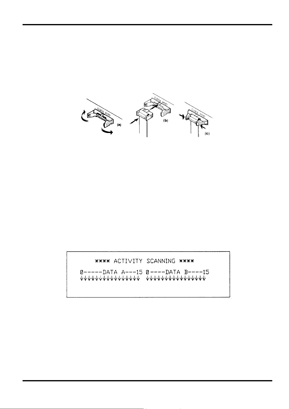
To connect a pod, proceed as follows:
i) Open out the latching levers of the connector, see fig 3.2.(a)
ii) Insert the socket at the end of the pod's cable into the corresponding connector on the rear
panel (TA320S) or front panel (TA320PC). The socket moulding is polarized with a 'bump' so
that it can only be inserted one way round, see fig 3.2.(b)
iii) Press the socket fully home and lock it in position by closing the latching levers, see fig
3.2.(c). The pod can be disconnected again by opening out the latching levers until the socket
is ejected.
fig 3.2
Connecting the Test Leads and Grabber Probes to the Pods
All pods are provided with colour-coded connecting leads which have a multi-pin socket at one
end (for connection to the pod) and which are individually terminated at the other end with
sockets that will connect to the pin of the optional grabber probes or to any other standard .025"
(0.64mm) square or 0.25" diameter pin, e.g. a wire-wrap post. Note that the socket may become
permanently deformed and loose-fitting if it is forced over a larger pin such as those of some IC
test clips (.030" or more).
For microprocessor disassembly a special test lead is provided which is terminated with a testclip for direct connection to the processor.
When connecting the input pods to the target system at least one ground lead on each pod must
be connected to the target to ensure signal integrity.
3.5 Activity Indication
Pressing <EDIT> whilst the main Select Menu is being displayed changes the display to that
shown in fig. 3.3.
The display is a representation of all 32 input channels, numbered according to the hardware
groupings used for the pod inputs.
When an input channel is below the pod threshold the indicator arrow points down, when it is
above the threshold it points up. The indicators track the input state for low frequencies but for
higher frequency signals the indicators will toggle at the rate at which the data is asynchronously
sampled by the CPU, i.e. a few Hertz.
3.6 Display Contrast
Use the CONTRAST control on the case lower to adjust for best LCD contrast with the analyser
set in its working position.
fig. 3.3
9
Page 11
4.1 Introduction
The Configuration menu, accessed by pressing the CONFIG soft-key on the Select Menu has
three principle functions. The first is the selection of the basic configuration of the instrument, i.e.
pod type and glitch on or off. The second is the clock selection including, if external clock is
selected, the specification of the active edges and qualifiers. Thirdly, the menu is used to specify
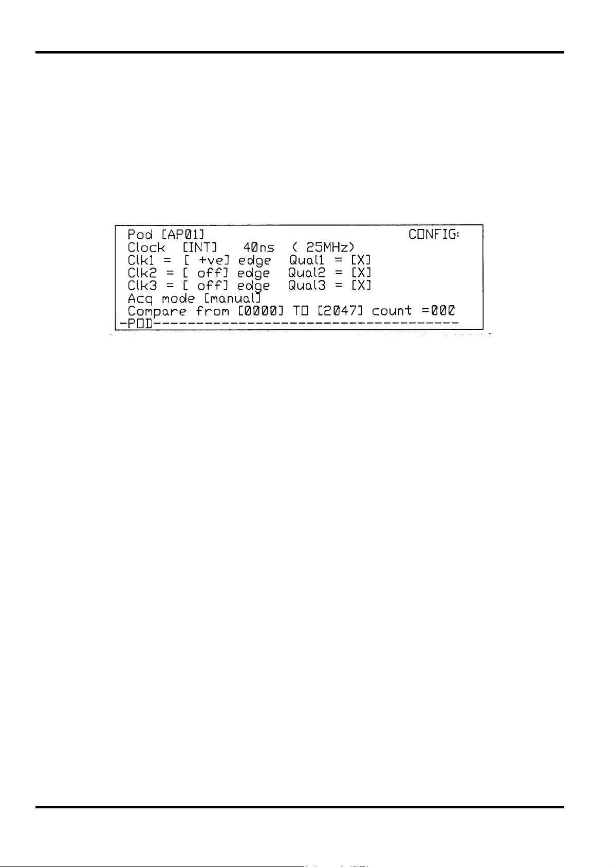
the acquisition mode, including the comparison ranges if automatic modes are selected.
Fig 4.1. shows the default Configuration menu immediately after selection from the Select Menu.
Section 4 - Configuration Menu
fig 4.1
The first 7 lines contain the parameters which are editable in this display. At the right-hand side of
the top line is the menu title (CONFIG); this area is used to display the status of the current
acquisition (e.g. <RUNNING>) or editing prompts and warnings (e.g. <SHIFT> when the shift
function is selected).
At the bottom are the soft-keys used when editing the display. In this menu all the parameters on
the same line can be edited at the same time so both the LEFT/RIGHT and UP/DOWN cursor
keys move the edit zone one line with each press and the soft-keys change accordingly.
Acquisitions can be initiated and stopped from the Configuration menu but no parameters can be
edited on the menu while the acquisition is running.
4.2 Pod Selection
-POD------------------------------------
Pressing the <POD> soft-key cycles the pod selection through AP01, AP03, AP03V and
DISSassembler in turn. When AP03 or AP03V is selected additional soft-keys are shown to
enable glitch to be selected, and when AP03V is selected further soft-keys permit threshold
selection, see sections 4.3 and 4.4.
4.3 Glitch Selection (APO3 and AP03V only)
POD----ON----OFF------------------------
Soft-key representation
Soft-key representation
10
With AP03 or AP03V selected in the Pod field (see 4.2) the soft-keys change to permit glitch
selection.
<ON> selects glitch on and <OFF> selects glitch off. In the top line of the display <glitch>
indicates that glitch is off and <GLITCH> (i.e. capitals) indicates that glitch is on.
If INTernal clock had already been set to 10ns (100MHz), selecting glitch on will force it to 40ns
(25MHz), the fastest clock rate compatible with glitch selection, see 4.5.
Page 12

With glitch on, the trigger WORDS and SEQuence menus will change to the glitch default settings
to permit only those set-ups compatible with glitch operation. This will happen immediately glitch
is set on (without accessing the other menus) which means that the channel groupings used in
the non-glitch mode will be lost and will not be restored when glitch is set off again.
However, if no acquisition has been run in the new configuration, the 'Last Run Set-up' can be
reloaded from the Utilities menu to restore the previous channel groupings, etc.
4.4 Pod Threshold Selection (AP03V only)
-POD----ON----OFF----TTL----INC----DEC—
With AP03V selected in the Pod field (see 4.2) the soft-keys change as shown above.
The thresholds are INCreased or DECreased from the default TTL (1.4V) level in 100mV steps
using the <INC> and <DEC> soft-keys. The TTL compatible threshold can be reset directly using
the <TTL> soft-key.
The range of values 'wraps-round' such that decreasing -2.5V by a further step sets the threshold
to 7.3V and increasing 7.3V by a further step sets the value to -2.5V. The set threshold is used
universally for the inputs of all data (AP03V) and clock (AP04V) pods.
4.5 Clock Specification
Soft-key representation
Internal Clock
At power-up the clock is defaulted to INTernal clock and 40ns period (25MHz); the soft-keys are
as shown above. With INT clock selected the clock period can be INCreased or DECreased in a
1:2:4 sequence using the <INC> or <DEC> soft-keys. For information only (i.e. it is not an
editable field) the equivalent clock frequency is shown in brackets after the clock period field.
The INTernal clock period can be set from 40ms (25MHz) to 40ns (25MHz) plus 10ns (100MHz)if
APO3 or AP03V have been selected. Note that the range of values 'wraps-round' such that
INCreasing the period when it is already at maximum (40ms) sets the clock to 40ns (10ns if
AP03/AP03V selected) and DECreasing the period when it is already at minimum sets the period
to 40ms.
Selecting 10ns (100MHz) whilst AP03 or AP03V are selected immediately sets the trigger
WORDS and SEQuence menus to the 100MHz default settings to permit only those entries
compatible with 100MHz operation. This means that channel groupings used in sub-100MHz
mode will be lost and will not be restored when 100MHz mode is deselected. If 10ns (100MHz)
has been selected with AP03 or AP03V, reselection of AP01 or DISSassembler pods will
automatically reset the clock to 40ns (25MHz) and any channel groupings set for 100MHz mode
will again be immediately lost. However, if no acquisition has been run in the new configuration,
the 'Last Run Set-up' can be reloaded from the Utilities menu to store the previous channel
groupings, etc. Even with AP03 or AP03V selected the maximum clock reverts to 25MHz if glitch
mode is selected.
INT/EXT-INC----DEC----------------------
Soft-key representation
External Clock
Alternate presses of the <INT/EXT> soft-key select between INTernal and EXTernal. At power-up
the clock is defaulted to INTernal and the first press of <INT/EXT> changes the clock to EXTernal.
With EXTernal clock selected the INTernal clock parameters are suppressed on the display and
the EXTernal clock operates in the way defined by the clock parameters on the next three lines of
the display. Maximum external clock frequency is 25MHz (minimum clock pulse width 20ns).
11
Page 13

External Clock Active Edge
Moving the edit zone into the <Clk 1>, <Clk 2> or <Clk 3> lines of the display changes the softkeys to those shown above. The active clock edge can be set to <+ve>, <-ve>, or <off> with
repetitive presses of the <CLK> soft-key. The active edge can be independently set for the 3
separate clock inputs. Setting the active edge to <off> disables that clock and its associated
qualifier.
External Clock Qualifiers
Pressing the <QUAL> soft-key increments the setting of the qualifier field through the possible
values of 1, 0 or X (don't care). The threshold value used for the qualifiers is the same as that set
for the data and clock inputs.
4.6 Acquisition Mode
Manual Mode
MANUAL--AUTO--=ref---=#ref--aborted------
-CLK----QUAL----------------------------
Soft-key representation
-CLK----QUAL----------------------------
Soft-key representation
Soft-key representation
When the edit zone is in the <Acq Mode> parameter field and <manual> is selected (the powerup default setting), the soft-keys are as above. The <=ref>, <=#ref> and <aborted> soft-keys
names are lower-case because they are inactive in <manual> mode. Pressing <AUTO> will
cause these 3 soft-keys to be made active, see Auto-repeat mode section. Pressing <MANUAL>
will return the instrument to manual mode.
In manual mode, a single acquisition is initiated by pressing the RUN key. Whilst the acquisition is
in progress the message <RUNNING> will be shown on the right-hand side of the top line of the
display. This message may change to a warning message <no clk> if RUN is pressed with
EXTernal clock selected but no clock signal connected. The <compare from to> field is
inoperative in <manual> mode.
Auto-repeat Mode
Pressing the <AUTO> soft-key whilst in manual mode changes the <Acq mode> parameter field
from <manual> to <repeat until> and makes the <=REF>, <=#REF> and <ABORTED> soft-keys
active. This is indicated by a change from lower-case to capitals for the soft-keys names. Now
when the RUN button is pressed acquisitions will be initiated, completed and re-initiated as
specified by the <repeat until> field. The message <RUNNING> will be shown on the right-hand
side of the top line of the display whilst the acquisition is running, but not between one acquisition
and the next. Auto acquisitions can be stopped at any time by pressing the STOP key which
operates as follows in auto-repeat modes. The first press of STOP during an auto acquisition
effectively changes the acquisition to manual mode; no further acquisitions are initiated when the
present one is completed. If STOP is pressed a second time before the acquisition is completed
then the acquisition is immediately terminated; no further acquisitions are initiated until RUN is
pressed again. However, between acquisitions, i.e. when <RUNNING> is not shown in the top
line of the display, only one press of STOP is required to inhibit further acquisitions.
MANUAL--AUTO--=REF---=#REF--ABORTED------
Soft-key representation
12
Page 14

Auto-repeat Conditions
Pressing <=REF> sets the condition that, when RUN is pressed, acquisitions will be repeated
until the acquired data matches the data held in reference memory for the specified store
locations and channels.
Pressing <=#REF> sets the condition that, when RUN is pressed, acquisitions will be repeated
until the acquired data does not match the data held in reference memory for the specified store
locations and channels.
Pressing <ABORTED> sets the condition that, when RUN is pressed, acquisitions will continue
until halted by pressing the STOP key as described previously. In each case, the number of
acquisitions made is shown in the <count=nnn> field. The maximum count is 999.
Compare Memory Range
Moving the edit zone down to the last line of the menu changes the soft-keys as shown above.
Alternate presses of the <FROM/TO> soft-key changes the field into which entries can be made
from <FROM nnnn> to <TO nnn>; the active field is the one in capitals into which numeric entries
can be made.
Keyboard entries are made 'calculator-style', i.e. store location 1000 is entered as 1,0,0,0; each
entry appears in the least significant position and increments the previous entry to the next
significant digit on the left. Four key entries fill the field; the next entry will be interpreted as the
first digit of a new store location and will therefore be shown in the least significant position with
all other digits shown as zeroes. A low-numbered location can be entered either as, for example,
0,0,2,1, or as 2,1,X where X terminates the entry; moving the edit zone out of the field also
terminates the entry. Both the start and stop store locations are included in the comparison. If the
start location is greater than the stop location, no comparison will be made. The default values of
the start and stop compare locations are 0000 and 2047 respectively. Comparisons will be made
only across those channels which have been given a label in the WORDS menu, i.e. channels
that have been switched off are masked from the comparison.
FROM/TO---------------------------------
Soft-key representation
13
Page 15

5.1 Introduction
The Trigger WORDS menu, accessed by pressing the WORDS soft-key on the main Select
Menu, is used to create the channel groups and to define up to 4 trigger words.
Fig 5.1. shows the WORDS menu with its power-up default values (assuming the Configuration
menu also has its default values).
Section 5 - Trigger Words Menu
The Trigger menu is edited by moving the edit zone to the parameter field of interest. The edit zone is
moved around the editable parameter fields by the
Acquisitions can be initiated and stopped from the Trigger menu but no parameters can be edited
on the menu while the acquisition is running.
5.2 Channel Group Labels
DEFAULT-CLEAR--OFF----------------------
A channel group is any block of contiguous channels grouped together under one channel group
label letter. A channel group may be from 1 to 32 channels wide and up to 16 different groups
may be specified and labelled with the letters <a> through <p>. A channel group may not be split,
i.e. all channels used in the group must be adjacent. If a label is split whilst labelling the channels,
the warning message <LABEL!> will be shown on the right-hand side of the top line of the display.
The label will be accepted (and labelling can continue) but the warning will continue to be
displayed and it will not be possible to move the edit zone from this line, or run an acquisition,
until the split label has been corrected.
Any letter <a> through <p> can be entered from the keyboard, using the SHIFT key for letters
<g> through <p>. As each letter is entered, the 'flashing' cursor automatically moves right to the
next channel so that its label can be edited. The 'flashing' edit cursor can also be moved to a
particular position using the LEFT and RIGHT cursor keys without disturbing the labelling of the
channels the cursor moves through.
The <CLEAR> soft-key can be used to clear all the channel groupings. Since clearing the labels
in this way may cause a complex set-up to be lost, two presses of the <CLEAR> soft-key are
required; after the first press the message <CONFIRM> is displayed on the right-hand side of the
top line of the display and a second press is required to actually implement the clear. Pressing
any other key instead of the <CLEAR> soft-key a second time will maintain the existing label
status and clear the warning message.
Pressing the <DEFAULT> soft-key sets the channel groupings to those shown in fig 5.1. Two
presses of the <DEFAULT> soft-key are necessary to implement the change, as for <CLEAR>.
Note that changing to and from 100MHz and glitch modes on the Configuration menu
immediately changes the WORDS menu to the appropriate default state. The channel grouping
used in the previous configuration is lost and not restored when the configuration is changed
back. However, if no acquisition has been run in the new configuration, the 'Last Run Set-up' can
be reloaded from the Utilities menu to restore the previous channel groupings, etc.
fig 5.1
cursor keys as described in section 3.
Soft-key representation
14
Page 16

5.3 Trigger Word Radix Selection
--BIN---OCT----HEX----------------------
Having grouped and labelled the data channels as required (section 5.2), the edit zone can be
moved to the radix field; the soft-keys change as shown above.
The base for each channel group can be independently set to be BINary, OCTal or HEXadecimal
using the appropriate soft-key. The RIGHT and LEFT cursor keys are used to move the edit zone
to each channel group in turn.
The base can also be changed with the edit zone in the trigger word fields, see section 5.4; this
section also explains how 'don't care' trigger word entries are handled by the software when the
base is changed.
5.4 Trigger Word Specification
--BIN---OCT----HEX-----------------FIND-
The trigger words themselves can be specified by moving the edit zone into each channel group
parameter field of the four trigger words in turn. The trigger words are defined by entering
characters from the keyboard consistent with the selected base of each channel group, viz. 0 and
1 for binary, 0 through 7 for octal and 0 through 9 plus A through F for hexadecimal. An X can be
used to denote a 'don't care' in any of the three bases. If there is not an exact multiple of 3
channels in an octal group, or an exact multiple of 4 channels in a hex group then the 'incomplete'
group will be the most significant bit in the appropriate base and the entries accepted in that bit
will be restricted accordingly. Thus an 8-channel group can have a trigger word specified in hex
between 00 and FF, but a 7-channel group with a hex base is restricted to entries between 00
and 7F.
Soft-key representation
Soft-key representation
As each bit is specified in the appropriate base, the 'flashing' cursor automatically moves right to
the next trigger bit. The 'flashing' cursor can also be moved to a particular position using the
RIGHT and LEFT cursor keys without disturbing the trigger bits that the cursor moves through.
As indicated by the available soft-keys, it is possible to also change the radix of the channel
groups whilst in the trigger word fields; the three soft-keys can be used to select the required
base for the channel group within which the edit cursor is currently positioned. If X (don't care) is
present in a trigger word when a radix change is made then the corresponding bit or bits in the
new base will be shown in one of the two following ways. Firstly, if an exact correspondence can
be shown in the new radix then X will appear in the appropriate bit(s); for example
1111XXXX(binary) will change to FX (hex) and vice-versa. However, if there is no exact
correspondence then an asterisk (*) will be displayed instead of an X; for example 1111111X
(binary) will be shown as F* (hex) to indicate that at least 1, but not all, of the 4 least significant
channels are don't care(s). Note that the original trigger word entry is always remembered in its
original base; it is always used in that form within the analyser and can be displayed again by reselecting that base. Thus 1111111X ( b i n a r y ) b e c o m e s F * ( h e x ) b e c o mes 1111111X (binary);
however, if F* (hex) is edited to FX (hex) then this becomes 1111XXXX (binary).
In 100MHz mode (AP03 and AP03V only) only the active channels (a0-a3 and b0-b3) are shown
and may be edited. The disabled channels are suppressed on the display and both the label and
trigger bit entries are replaced by <.>.
Similarly when glitch is on only the 8 active channels of each pod (a0-a7 and b0-b7) are shown.
Channels disabled for these reasons are also suppressed on the Timing and List displays.
15
Page 17

5.5 Find Word Specification
--BIN---OCT----HEX-----------------FIND-
Any one of the trigger words can additionally be specified as a FIND word for use in a search of
the LIST display. The default FIND word is Word 1 and this is indicated by an <F> next to the
<Wd1> name. To make another trigger word the FIND word, move the edit cursor to any bit within
that word with the cursor keys and press the <FIND> soft-key. The <F> marker will move to that
word.
5.6 Glitch Triggering (AP03 and AP03V only)
If glitch has been selected on in the Configuration menu then the Trigger WORD menu changes
from showing Word 4 to the glitch trigger word <GLT> in the last line above the soft-keys,
see fig. 5.2.
Soft-key representation
fig 5.2
With the edit cursor in this field the soft-keys change to:
--OFF---ON------------------------------
Soft-key representation
Pressing the <ON> key enters a <G> on the glitch channel where the 'flashing' edit cursor is
positioned and automatically steps the cursor to the next channel; pressing <OFF> enters an X
(don't care); G and X can also be entered directly from the keyboard. The RIGHT and LEFT
cursor keys can be used to move the edit cursor through the field without affecting the bits
already set.
The glitch trigger word (<GLT>) is the ORed combination of any glitches specified. This glitch
word can then be used in the sequencer specification in the usual way, see section 6. The glitch
word cannot be used as a <FIND> word.
16
Page 18

6.1 Introduction
The Trigger Sequence menu, accessed by pressing the SEQ soft-key in the main Select Menu is
devoted entirely to the trigger sequence itself. For clarity, the full trigger sequence construction is
always shown even if it is not fully utilised or, as in the case of 100MHz operation, is not fully
available. Fig 6.1. shows the default sequencer menu at power-up, assuming the Configuration
menu also has its default values set.
The sequencer has four steps followed by the trigger position specification. Each step consists of
specifying the trigger term to be found, the number of times it must be found, and the restart term
which will cause the sequence to be restarted; the trigger position field allows the trigger to be
positioned up to 5,000 clocks before the start, centre or end of store. These parameters are
explained fully in the following sections.
Section 6 - Trigger Sequence Menu
fig. 6.1
6.2 The Find Term
With the edit zone in the <find> term field of any of the 4 sequence steps, the soft-keys are as
shown above.
The <find> term is any ORed combination of the 4 trigger words. Trigger words are added or
deleted from the <find> term with alternate presses of the corresponding <Wd1> through <Wd4>
soft-keys; the keyboard keys <1> through <4> can also be used. The trigger words will always be
shown in numerical order in the <find> term, regardless of the order in which they have been
entered.
The <X> soft-key can be used to make the whole term 'don't care'. Note that, to ensure a valid
sequence is always constructed, <x> default don't cares are automatically inserted into 'empty'
sequence steps followed by an active step. The use of a lower-case <x> differentiates the 'don't
care' from one deliberately inserted (<X>) but the sequence operates in the same way in both
cases.
The <CLEAR> soft-key is an alternative, quicker, way of clearing all words from the term.
When glitch is selected on (AP03 and AP03V pods only) a glitch trigger word can be set up in the
Trigger Words menu, see section 5, and on the sequencer menu soft-key <Wd4> is replaced by
<GLT> the glitch trigger word. Alternate presses of <GLT> insert the glitch trigger word in the
<find> term in the same way as for trigger words <Wd1> through <Wd3> and the <find> term
becomes the OR'ed combination of the specified words.
--Wd1----Wd2----Wd3---Wd4---CLEAR---X---
Soft-key representation
In 100MHz mode the sequence is restricted to a single <find> term.
17
Page 19

6.3 Trigger Event Delay
Moving the edit zone to the <n clks> field in any of the sequence steps gives the soft-key display
shown above. The number of times that the trigger term must be found (before the sequencer is
incremented to the next step) is set in this field.
Up to 128 counts of the trigger term can be specified, either by using the <INC> and <DEC> softkeys or (more quickly for larger counts) by direct decimal entries from the keyboard. If a count of
0 is entered from the keyboard, a warning message <illegal value> is displayed at the right-hand
side of the top line of the display; the count will default to 001 when the field is exited. If a count of
greater than 128 is entered from the keyboard, the entry defaults to 128. Keyboard entries are
made 'calculator-style' as described more fully in section 4.
The count can always be returned to its minimum value 001) by pressing the <N=1> soft-key.
No event count is available in 100MHz mode.
6.4 The Restart Term
--Wd1----Wd2----Wd3---Wd4---CLEAR---X---
INC----DEC----N=1----------------------
Soft-key representation
Soft-key representation
With the edit zone in the <restart if> field of any of the 4 sequence steps, the soft-keys are as
shown above.
The restart feature adds a conditional capability to the trigger sequencer which resets the
sequencer to the step 1 <find> term if the specified <restart if> term is found. The <restart if> term
is any ORed combination of the 4 trigger words. Trigger words are added or deleted from the
<restart if> term with alternate presses of the corresponding soft-keys <Wd1> through <Wd4>;
the keyboard keys <1> through <4> can also be used. The words will always be shown in
numerical order in the <restart if> term, regardless of the order in which they have been entered.
The <X> soft-key can be used to make the whole term 'don't care'. The <CLEAR> soft-key is an
alternative, quicker, way of clearing all words from the term.
No restart capability is available in 100MHz mode since it is meaningless in a single-step
sequence.
6.5 Trigger Position
Moving the edit zone down from sequence step 4 into the trigger position fields enables both the
clock count and the reference position to be entered using the soft-keys shown above.
The power-up default condition is <0k> clocks before the start of store; the trigger word is put in
store location 0000 and the store is filled with the samples following the trigger word. This set-up
ensure that a complete store full of data is acquired even if the trigger words are all don't care.
--INC---DEC----N=0---END---START---50%--
Soft-key representation
18
If the trigger position is selected to be <0k> clocks before the end of store by pressing the <END>
soft-key then the trigger word is positioned at the end of the stored data. Note that if the trigger
word is recognised within the specified store depth then the store will not be completely filled; the
first store location will contain the first sample of data acquired after pressing RUN and the last
stored sample will be the trigger word. An extreme example of this is if the trigger is recognised
immediately the acquisition is initialised; the store will be empty except for the trigger word
positioned at the first location.
Page 20

Similarly, if the trigger position is selected to be <0k> clocks before the centre of store by pressing
the <50%> soft-key then the trigger word is positioned half the store before the last stored
sample; if the trigger is recognised within half the store of initiating the acquisition then the
second half of the store will be correspondingly partly empty.
It is possible to position the trigger elsewhere in the store, or before the start of store, in steps of
1k clocks using the <trigger nk clks before> field.
The trigger delay clock count is INCreased or DECreased in 1k steps using the <INC> or <DEC>
soft-keys; it can also be specified by direct decimal entries from the keyboard in the range 0 to 5.
The count can always be returned to its default value of <0k> by pressing the <N=0> soft-key.
6.6 Trigger Output
The <TRIGGER OUT> signal at the rear panel BNC connector is a TTL level signal which goes
high when the last trigger term in the sequence is found, i.e. before the delay by clocks (if used).
19
Page 21

7.1 Introduction
The Timing display is accessed by pressing the TIMING soft-key in the main Select Menu.
Section 7 - Timing Display
fig 7.1
The top line of the display is an information line giving the current magnification, a graphical
representation of the part of the store currently being displayed, plus cursor, marker and
difference location readouts.
Below the information line are 6 lines for the display of data; channels can be displayed and
repeated in any order. Any channel can be brought into view, either by scrolling it into the display
with the UP and DOWN cursor keys, or by direct editing. To the left of each displayed line is the
name of the channel; this is either the default channel group label, or a channel group name that
can be given to it in the edit mode of this display.
At power up the data displayed is that from the last acquisition but the channels will be in default
order, see 7.8.Striking vertically through the lines of data are a movable cursor and marker; the
cursor and marker are themselves marked <c> and <m> respectively at the top of the vertical
lines, above the first line of timing data. Either the cursor or marker may be designated active at
any one time, i.e. made movable by the arrowed RIGHT and LEFT cursor keys. Magnification of
the data by up to x16 is possible; magnification is always about the cursor, <c>. A graphical
representation of the store area currently being displayed is shown in the information line above
the data area.
Down the right-hand side of the data area is a column of characters, one character for each line
of waveform data. This column can be selected to give a readout of the cursor or marker
positions, or can be used to specify a FIND word used in a search of the Timing display.
There are no soft-keys until edit mode is entered by pressing the <EDIT> key; in edit mode the
last line of channel data is replaced by soft-keys which change with the position of the edit zone,
as in the menu displays.
Acquisitions can be initiated and stopped from the Timing display and the display can be
manipulated while the acquisition is running although the speed of operation will generally be
slower.
7.2 Active Cursor Marker Selection and Move
-MAG>---MAG<-CUR/mar-ACQ/ref-----EX-FIND
Either the cursor or the marker is selected to be active at any one time. The one currently active
is indicated by displaying it as a capital letter in the <C=nnnn> or <M=nnnn> position field in the
information line at the top of the display; the inactive one is displayed with a lower-case <c> or
<m>. In fig 7.1 the cursor is active. Only the one currently active can be moved by the RIGHT and
LEFT cursor keys or by direct entries from the keyboard. Moving the cursor and marker on the
Timing display also moves them on the List display.
20
Soft-key representation
Page 22

To change which one is active it is necessary to enter edit mode by pressing the <EDIT> key. The
bottom line of the display shown in fig. 7.1. is replaced by the soft-keys shown above if the cursor
is in its default position.
Marker or cursor are set active with alternate presses of the <CUR/mar> soft-key; as well as
showing <C=nnnn> or <M=nnnn> in capitals, the active one is shown by using capitals for
<CUR> or <MAR> in the soft-key itself.
The information line at the top of the display gives the cursor and marker absolute store locations
in the fields <C=nnnn> and <M=nnnn> respectively.
Each location corresponds to a clock sample, either internal or external as defined on the
Configuration menu; the interval of the internal clock, if used, is only shown on the Configuration
menu. The one currently active is indicated with a capital <C> or <M> and, having exited edit
mode, direct numeric entries can be made to that field to move the cursor/marker quickly.
Keyboard entries are made 'calculator-style', i.e. store location 1000 is entered as 1,0,0,0; each
entry appears in the least significant position and increments the previous entry to the next
significant digit on the left. Four key entries fill the field and on the fourth entry the cursor/marker
is moved to the specified location; the next entry is then interpreted as the first digit of a new
location. To move to a low-numbered location the entry can either be made as, for example,
0,0,2,1, so that the move is made on the fourth (1) entry key press, or it can be entered by
pressing 2,1,X, where X terminates the entry and causes the cursor/marker to move. High
numbers, outside the range of the currently selected store depth, are accepted but the cursor will
only move to the highest location in the store. Note that, when the active cursor/marker is being
moved with the RIGHT and LEFT cursor keys, the cursor/marker initially moves slowly but then
speeds up if the key is kept depressed; releasing the key and pressing again (as the
cursor/marker approaches the desired location) moves it slowly once more.
7.3 Acquisition Reference Memory Selection
-MAG>---MAG<-CUR/mar-ACQ/ref-----EX-FIND
With edit mode selected by pressing the <EDIT> key, the soft-keys are as shown above. The
memory whose contents are to be displayed is selected with alternate presses of the <ACQ/ref>
soft-key; the currently active memory is shown in capitals within the soft-key itself, the inactive
one in lower-case letters. The acquisition memory is the memory in which the most recently
acquired data is stored.
The reference memory may have been loaded from the previous acquisition or any earlier
acquisitions saved in non-volatile memory, see section 9.
7.4 Glitch Display
-MAG>---MAG<-CUR/mar-ACQ/REF-glt-EX-FIND
With edit mode selected by pressing the <EDIT> key, the soft-keys are as shown above. If the
data being displayed was acquired with glitch mode selected on the Configuration menu (AP03,
AP03V only), then an additional <glt> (glitch) soft-key will show to the right of the ACQ/ref key.
Alternate presses of the <glt> soft-key will then turn the display of glitches on or off; the current
status of the glitch display is shown by displaying <GLT> in capitals for glitch on and <glt> (lowercase) for glitch off.
Soft-key representation
Soft-key representation
Glitches are shown on the display as vertical lines extending both above the logical '1' level and
below the logical '0' level. As a reminder that only channels 0 through 7 of each pod are active
when glitch is selected, they are marked with a lower-case <g> following their channel group
name at the left-hand side of the data line.
21
Page 23

7.5 Display Magnification
-MAG>---MAG<-CUR/mar-ACQ/ref-----EX-FIND
With edit mode selected by pressing the <EDIT> key, the soft-keys are as shown above. The
display magnification can be increased and decreased from x1 to x16 in multiples of 2 using the
<MAG>> and <MAG<> soft-keys respectively.. The range of values 'wraps-round' so that
INCreasing the magnification by a further step when it is already at x16 will set it to x1, and
DECreasing the magnification by a further step when it is already at x1 will set it to x16; this can
be used to get from minimum to maximum magnification very quickly, and vice-versa. The current
magnification factor is always shown in the <mag => field in the information line at the top of the
display.
In the information line there is also a graphical representation of the area and 'depth' of the
currently displayed data. The whole store is defined by the single line below the <M=> and <CM=> fields and the extent and position of the currently displayed data is shown by the shorter line
on top of the full line. Note that, since less than 2k samples can be displayed at once, the line
indicates that only about 1/2 of the store is currently being displayed with the magnification at x1.
7.6 Data Searching in the Timing Display
-MAG>---MAG<-CUR/mar-ACQ/ref-----EX-FIND
Soft-key representation
Soft-key representation
With edit mode selected by pressing the <EDIT> key, the soft-keys are as shown above. A search
for the specified <FIND> word can be made at any time by pressing the <EX-FIND> soft-key. If
the word is found, the cursor will move to that store location; subsequent presses of the <EXFIND> soft-key will move the cursor to the next higher store location at which the word is found,
and so on until the end of the store is reached.
To set up the <FIND> word the edit zone must first be moved to the right-hand 'readout' column
by one press of the RIGHT cursor key (from the default position); the soft-keys then change to
those shown below:
--------FIND--CURSOR--MARK-------EX-FIND
Soft-key representation
The <FIND>, <CURSOR> and <MARK> soft-keys are then used to select the function of this
column:
<FIND> : column becomes the <FIND> word and binary entries can be specified from the
keyboard; as each entry is made the edit cursor automatically moves down to the
next line. The edit cursor can also be moved up and down the column by the
arrowed UP and DOWN cursor keys. If glitch display is on (see section 7.4) then
the <FIND> can also be specified to search for glitches by entering G instead of
0, 1 or X in the <FIND> bits of the glitch channels.
The search is made across all channels currently turned on in the Timing display
(see section 7.8), not just those currently view. When the channel order is edited
the <FIND> bit moves with its associated channel. A search can be initiated
without the <FIND> being displayed.
22
<CURSOR> : column becomes the readout, in binary, of the store contents at the location of the
cursor <c>.
<MARK> : column become the readout, in binary, of the store contents at the location of the
marker <m>.
Page 24

7.7 Channel Group Names
-------SPACE----/-----*------?-----CLEAR
Moving the edit cursor down with the DOWN cursor key from its default position (when edit mode
is first selected) changes the soft-keys to those shown above.
Each of the 16 possible channel groups can be given a 4-character channel group name in place
of the <A...>, <B...>, <C...>, etc, default "names" which correspond to the labels <a>, <b>, <c>,
etc., allocated in the trigger <WORDS> menu. With the edit cursor positioned over the first
character of any default channel name within the group to be changed, a new name can be
entered from the keyboard. Any number or character can be used in the channel group name,
including the four special characters available on the soft-keys, i.e. <SPACE>, </>, <*> AND <?>.
As each character is entered the 'flashing' cursor automatically moves to the next character to be
edited; it can also be moved to a particular position using the LEFT and RIGHT cursor keys. The
<CLEAR> soft-key blanks the whole name, and moves the edit cursor to the first position to allow
a new name to be entered.
When there is more than 1 channel in a group changing the name of any channel in the group
renames all the channels in that group. However, each channel in the group is automatically
uniquely numbered. For example, if there are 4 channels grouped under a label and given the
name <DATA>, the Timing display will show the 4 channels labelled as <DATA0> through
DATA3>. Note that because the channel name is restricted to 5 characters including the
automatically added numbers, 4-character names are truncated to 3 characters for groups with
channel numbers greater than 9. For example, a channel group of 16 channels with a channel
name <DATA> will have the channels named on the Timing display as <DATA0> through DATA9>
and <DAT10> through <DAT15>.
Soft-key representation
7.8 Editing the Timing Display
INSERT-DELETE--NEXT--PREV-DEFAULT-------
Soft-key representation
Moving the edit cursor to the right of any channel name with the RIGHT cursor key changes the
soft-keys to those shown above. The default order in which the data channels are displayed at
power up is channel 0 through channel 15 of DATA A followed by channel 0 through 15 of DATA
B, where DATA A and DATA B are the hardware channel groupings defined by the analyser input
connectors and the pods themselves. The data channels can, however, be repeated and
displayed in any order using the 5 soft-keys.
With the edit zone positioned to the right of any channel name, the five soft-keys have the
following functions:
<DEFAULT> returns the channel order to the default setting. Pressing <DEFAULT> once causes
the warning message <CONFIRM> to be displayed at the right-hand side of the top
line of the display; it is necessary to press it a second <DEFAULT>. Pressing any
other key instead of a second press of <DEFAULT> will prevent the default from being
implemented.
<DELETE> deletes the data channel over which the edit zone is positioned; all the channels below
that line are immediately scrolled up one position and the edit zone therefore
effectively becomes positioned over what was the next data channel.
<NEXT> changes the data channel displayed at the edit zone position to the next data channel
as defined by the hardware, e.g. if the edit zone is at channel 14 of DATA A, the data
channel will change to channel 15 of DATA A, then channel 0 of DATA B etc.
23
Page 25

<PREV> changes the data channel displayed at the edit zone position to the previous data
channel as defined by the hardware, e.g. if the edit zone is at channel 14 of
DATA A, the data channel will change to channel 13 of DATA A, then channel 12 of
DATA A, etc.
<INSERT> scrolls all the data channels below the edit zone down 1 line with each press. The line is
left blank until a data channel is inserted using the <NEXT> and <PREV> keys. If the
<NEXT> key is the first key pressed after <INSERT> then channel 0 of DATA A will be
inserted and further presses of <NEXT> will increment the line forward through all the
channels in their hardware order as described for <NEXT> above. If the <PREV> key is
the first key pressed after <INSERT> then a blank will be inserted and further presses of
the <PREV> key will decrement the line back through all the channels in their reverse
hardware order as described for <PREV> above.
Note that there is effectively a 33rd line which is a 'blank'; if the line is incremented with the
<NEXT> key through all possible channels, a further press of <NEXT> will make the line blank;
one more press will bring channel 0 of DATA A into view, etc. Similarly, pressing <PREV> with the
edit zone over channel 0 of DATA A will make the line go blank and another press will bring
channel 15 of DATA B into view, etc. In 100MHz or glitch modes (APO3/APO3V only) the
unavailable channels are automatically suppressed on the Timing display. When standard 32channel mode is reselected (no 100MHz or glitch) the channels remain suppressed, if an
acquisition had been made in 100MHz or glitch mode, until a new acquisition is taken. The
channels that are available when a configuration is changed will be shown in whatever position in
the Timing display they were last edited into.
24
Page 26

8.1 Introduction
The List display is accessed by pressing the LIST soft-key in the main Select Menu.
Data from 6 consecutive store locations and the numbers of the locations are listed in channel
groups headed by the channel group label and group base. The cursor is always positioned in the
top line of the display and is not marked; the marker position is indicated by an <m> immediately
to the right of the store location column. At power-up the data displayed is that from the last
acquisition but only the default channel groups <a> and <b> will be listed.
There are no soft-keys until edit mode is entered by pressing the <EDIT> key; in edit mode the
last line of data is replaced by soft-keys which change with the position of the edit zone, as in the
menu displays. Acquisitions can be initiated and stopped from the List display and the display can
be manipulated while the acquisition is running although the speed of operation will generally be
slower.
Section 8 - List Display
fig 8.1
8.2 Cursor Move
The data at the store location at which the cursor is present is always displayed on the top line,
i.e. the cursor is always at the top line of the data display. The UP cursor key moves the cursor to
the next higher store location (auto-repeating if kept pressed); since the cursor is always
positioned on the top line of the display, this has the effect of scrolling the data up the display. The
data can be scrolled up the display until the last valid store location is brought into the display.
Similarly, the DOWN cursor key moves the cursor to the next lower store location; ie. scrolls the
data down the display. The data can be scrolled down the display until the first valid store location
is in the top line of data.
Fast cursor moves can be achieved using the <P>UP> and <P>DOWN> soft-keys available in
edit mode which respectively scroll the data up and down by 6 locations at each key press.
The cursor can also be moved with a direct keyboard entry. Keyboard entries are made
'calculator-style', i.e. store location 1000 is entered as 1,0,0,0. The first entry enters the number in
the least significant position; each subsequent entry appears in the least significant position and
increments the previous entry to the next significant digit on the left. Four key entries fill the field
and on the fourth entry the cursor is moved to the specified location.
To move to a low-numbered location the entry can either be made as, for example, 0,0,2,1, so
that the move is made on the fourth (1) key press, or it can be entered by pressing 2,1,X, where X
terminates the entry and causes the cursor to move. High numbers, outside the range of the
currently selected store depth, are accepted but the cursor will only move to the highest location
in the store. Moving the cursor in List display also moves it to the same store location in Timing
display.
The LEFT and RIGHT cursor keys are used to scroll all the channel groups into view if they
cannot be viewed simultaneously; this situation can arise if channel groups with a large number of
channels are repeated several times in a 'wide' base, e.g. binary, see section 8.6. Additional
channel groups to the right are indicated by the > symbol on the far right of the group label line;
these groups can be brought into view by pressing the RIGHT cursor key. Similarly, groups to the
left of the channels in view are indicated by the < symbol and can be brought into view by
pressing the LEFT cursor key.
25
Page 27

8.3 Acquisition Reference Memory Selection
-FND1-compare-diff-ACQ/ref-P>DOWN--P>UP-
With edit mode selected by pressing the <EDIT> key and the edit zone moved to the bottom line
of the display with 2 DOWN cursor presses, the soft-keys are as shown above. The memory
whose contents are to be displayed is selected with alternate presses of the <ACQ/ref> soft-key;
the currently active memory is shown in capitals within the soft-key itself, the inactive one in
lower-case letters.
The acquisition memory is the memory in which the most recently acquired data is stored. The
reference memory may have been loaded from the previous acquisition or any earlier acquisitions
saved in non-volatile memory, see section 9.
8.4 Data Searching in the List Display
-FND1-Compare-diff-ACQ/ref-P>DOWN--P>UP-
A search for a particular word can be made at any time by pressing the <FIND> soft-key. If the
word is found, the cursor will move to that store location; subsequent presses of the <FIND> softkey will move the cursor to the next higher store location at which the word is found, and so on
until the end of the store is reached. The word to be found is the trigger word marked with an
<F> in the WORDS menu, see section 5.5; if <WD1> was marked as the <FIND> word then the
soft-key is shown as <FND1> in the List display, if <Wd2> then it is shown as <FND2> etc.
Soft-key representation
Soft-key representation
Any number of words can be searched for by editing the trigger word(s) specified as a <FIND>
word and re-running <FIND n> on the same data, i.e. a search is not restricted to the words used
in the trigger sequence of the acquisition itself. The search for a specified word is made across
the full width of the data, not just the channels displayed, and ignores the order and base of the
displayed channels. If a search is to be restricted to a certain group of channels then 'don't cares'
must be specified in the remaining channels on the trigger WORDS menu, see 5.4, or the
unwanted channels must be turned off, see 5.2.
8.5 Compare and Find Difference in the List Display
-FND1-Compare-diff-ACQ/ref-P>DOWN--P>UP-
Soft-key representation
A comparison between the acquisition and reference memories can be switched on and off with
alternate presses of the <compare> soft-key; the current ON condition is indicated within the softkey itself by showing <COMPARE> in capitals. Differences are shown with an asterisk (*). When
COMPARE is ON, the <DIFF> soft-key becomes active, indicated by showing <DIFF> in capitals.
A search for a difference can be made by pressing the <DIFF> soft-key whilst the COMPARE is
ON. If a difference is found, the cursor will move to that store location; i.e. the difference will move
to the top line of the display. Subsequent presses of <DIFF> will move the cursor to next higher
store location at which a difference is found, and so on until the end of the store is reached. A
search for a difference applies only to those channel groups currently being viewed, i.e. the
search ignores channels not displayed and channels that have 'overflowed' the display to the left
and/or right.
26
Comparisons with the reference memory are possible even if the reference memory contains data
acquired under different conditions, eg. 100MHz configuration or glitch on. However, such
comparisons will be meaningless and it is left to the user to ensure that comparisons are only
made between memories that have data acquired under identical conditions.
Page 28

8.6 Editing the List Display
Fig 8.1. shows the 'default' List display after running an acquisition with the default parameters of
the Configuration and Words menus; the data is listed in binary in the 2 default channel groups
(group <a> for the DATA A channels, etc.). Note that at switch-on the data displayed will always
be that from the last acquisition but it will be displayed in the default format; to display it in the
correct format it is necessary to recall the last run set-up from non-volatile memory, see section 9
By entering edit mode using the <EDIT> key, the channel groups displayed, and the base they
are displayed in, can be edited.
Editing Channel Groups in List Display
INSERT-DELETE--NEXT--PREV--DEFAULT-NAME-
With the edit mode selected by pressing the <EDIT> key, the soft-keys are as shown above with
the edit zone in the label line. The RIGHT and LEFT cursor keys move the edit zone along the
label line from one channel group to an adjacent one.
The only channel groups which can be displayed are those which have already been defined in
the trigger WORDS menu, see section 5.2. In 100MHz or glitch modes, the groups displayed are
further restricted to those of the channels which are operational in such configurations. When
standard 32-channel mode is reselected (no 100MHz or glitch) the channels remain suppressed,
if an acquisition had been made in 100MHz or glitch mode, until a new acquisition is taken. The
channel groups can be displayed in any base (not necessarily the base used for that group in the
Trigger menu), any number of times and in any order, within the overall constraint of a maximum
of 16 channel groups. If channel groups containing a large number of channels are repeated a
number of times such that they cannot all be shown on the screen at once then it will be
necessary to scroll the groups into the display using the LEFT and RIGHT cursor keys, see
section 8.2.
Soft-key representation
With the edit zone positioned in the channel label line the soft-keys have the following functions:
<DELETE> deletes the channel group over which the edit zone is positioned; all the channel groups on
the right of the deleted group are immediately scrolled to the left and the edit zone
therefore effectively becomes positioned over what was the next group to the right.
<NEXT> changes the channel group displayed at the edit zone position to the next channel group (in
alphabetical order), of those channel groups specified on the trigger WORDS menu.
<PREV> changes the channel group displayed at the edit zone position to the previous channel
group (in reverse alphabetical order) of those channel groups specified on the Trigger
WORDS menu.
<INSERT> scrolls the channel group at which the edit zone is positioned, and all channels to its right,
over to the right; the edit zone is blank until the channel group to be inserted is specified
using the <NEXT> and <PREV> keys or direct entries from the keyboard. If the <NEXT>
key is the first key pressed after <INSERT> then the channel group which is first in
alphabetical order will be inserted and further presses of <NEXT> will increment the
channel group forward through all possible choices as described for <NEXT> above. If the
<PREV> key is the first key pressed after <INSERT> then the channel group which is last
in alphabetical order will be inserted and further presses of <PREV> will decrement the
channel group backward through all possible choices as described for <PREV> above.
The channel group label to be inserted can also be entered directly from the keyboard by
pressing the appropriate key (and using SHIFT for characters g through p) after <INSERT>;
only labels for those channel groups already specified on the trigger WORDS menu will be
accepted from the keyboard.
When channel groups are inserted they are listed in the default base of binary; see the next
section for changing the channel group base.
27
Page 29

With the edit zone positioned over a channel group the label can also be edited by a direct entry
from the keyboard (using SHIFT for labels g through p). The <DEFAULT> soft-key can be used to
display the default groups (<a> and <b>) provided they were specified on the trigger WORDS
menu. Since defaulting the channel groups in this way may cause a complex arrangement to be
lost, two presses of the soft-key are required; after the first press the message <CONFIRM> is
displayed on the right-hand side of the top line of the display and a second press is required to
actually implement the default. Pressing any other key instead of <DEFAULT> a second time will
maintain the existing group status and clear the warning message.
At any time, the channel group names allocated to each label on the Timing display (see section
7.7) can also be shown on the List display be pressing the <NAME> soft-key. When <NAME> is
pressed the channel group labels change to channel group names and the soft-key changes to
<LABEL>; pressing <LABEL> reverts the names to labels. The number of characters from the
name that will be displayed will depend on the number of channels in that group and the selected
base.
Editing Channel Bases in List Display
-BIN----OCT----HEX---DEC----ASCII-------
Moving the edit zone to the channel base line with the DOWN cursor key causes the soft-keys to
change to those shown above. The RIGHT and LEFT cursor keys are used to move the edit
zone to each channel group in turn.
Soft-key representation
The base for each channel group can be independently set to be BINary, OCTal, HEXadecimal,
DECimal, ASCII, or OPTION (microprocessor mnemonics) using the appropriate soft-keys.
The OPTION base can only be specified (and the <OPTIONS> soft-key will only be displayed) if
options have been installed, see section 9.
28
Page 30

9.1 Introduction
The Utilities menu, accessed by pressing the UTILities soft-key on the Select Menu, has four
principle functions. The first is the specification of the variable RS-232 interface parameters; the
second is control of the LIST display print capability; the third is the transfer of data and set-ups to
and from non-volatile memory; lastly, the menu is the means by which disassembler options are
loaded. Fig 9.1. shows the Utilities menu with its power-up default values.
The Utilities menu is edited by moving the edit zone to the appropriate line. More than one field
can be edited at a time (e.g. all RS-232 parameters), using the appropriate soft-keys, without
extra cursor moves. Acquisitions can be initiated and stopped from the Utilities menu but no
parameters can be edited on the menu while the acquisition is running.
Section 9 - Utilities Menu
fig 9.1
9.2 Setting up the Interface Parameters
Fig 9.1 shows the Utilities menu with its power-up default values. With the edit zone positioned
against the top line the soft-keys are:
-PC02---1200---4800---9600--ADD>---ADD<-
The only parameters that can be changed are the Baud rate and the ARC (Addressable RS232
Chain) address. Data bits, stop bits and parity are fixed at 8, 1, and none respectively, the
standard settings for an ARC interface. This is shown by the (8, 1, n) field in the top line of the
display which cannot be edited. The Baud rate and ARC address are stored in non-volatile
memory at power-off and restored at power-on.
The Baud rate can be directly set to 1200, 4800 or 9600 by using the appropriate soft-key. The
additional "Baud" setting of <PC02> is for outputting to a parallel printer via the PC02 serial-toparallel converter, see section 9.3.
The address can be incremented or decremented through the range 00 to 31 using the ADD> or
ADD< soft-keys respectively. The additional "address" setting of <PC> is the non-ARC setting
specifically for printing, see section 9.3, and remote-control via the TA-PC Link software option.
This option provides full control of the analyser from IBM compatible PCs and makes full use of
the larger screen in both setting up on a single menu and displaying results.
9.3 Printing the List Display
Soft-key representation
Moving the edit zone to the "Print LIST from CURSOR to [nnnn]" line leaves just the <PRINT>
soft-key showing at the extreme left. The List display can be printed out from the current cursor
position to the store location defined in the [nnnn] field. Entries to this field are made "calculatorstyle" from the keyboard; entries beyond the maximum store depth (2048 and above) default to
2047. The columns of data printed out are those currently shown on the analyser's LCD; data
"off-screen" to left or right is not printed. For use with a serial printer the Baud rate is set to
<9600>,<4800>, or <1200> to suit the printer; for use with a parallel printer (via a PC02 serial-toparallel converter) the Baud rate is set to <PC02>, see section 9.2. In both cases the <address>
must be set to <PC>, the non-ARC mode, see section 9.2.
29
Page 31

Having set up the interface parameters printing can be initiated by pressing the <PRINT> soft-key
twice; the first press causes the messages <CONFIRM> to be displayed on the right-hand side of
the top line of the display and a second press is required to actually start the printing. Printing can
be aborted at any time by holding down the <STOP> key; this is useful if, for example, printing
was initiated without a printer connected or if the printer runs out of paper, etc.
9.4 Data Transfer to and from Non-Volatile Memory
EXECUTE(ACQ---REF---STORE)to(REF---STORE)
Soft-key representation
Moving the edit zone down to the 'Copy store' line changes the soft-keys to those shown above.
The three soft-keys in the left-hand group (<ACQ>, <REF>, and STORE) are used to specify the
memory from which data is to be transferred; the current source memory is shown in the field
after 'from'. Acq and ref are entered directly by the <ACQ> and <REF> soft-keys and the
additional stores 1 through 10 are specified by stepping through with the <STORE> soft-key until
the desired store is shown in the 'from' field.
Similarly the right-hand <REF> and <STORE> soft-keys are used to specify the target store
destination in the 'to' field. Note that it is not possible to save data back to the acquisition memory.
Once the 'Copy store from [-] to [-]' statement has been set as required the actual data transfer
can be initiated by pressing the <EXECUTE> soft-key. The first press of <EXECUTE> causes the
message <CONFIRM> to be displayed on the right-hand side of the top line of the display and a
second press is required to actually execute the transfer. Pressing any other key instead of
<EXECUTE> a second time will cancel the transfer.
Note that the acquisition and reference memories are non-volatile too and their data is
automatically retained at power down.
9.5 Set-up Transfer to and from Non-Volatile Memory
EXECUTE-(ACQ--SETUP)--to---(ACQ---SETUP)
Soft-key representation
Moving the edit zone down to the 'Copy setup' line changes the soft-keys to those shown above.
Two soft-keys (<ACQ> and <SETUP>) on the left define the source memory and two soft-keys
(<ACQ>and<SETUP>) define the target memory. In both cases <ACQ> enters 'acq' into the 'from'
or 'to' field directly and <SETUP> steps through the 10 possible set-up memories in turn with
successive presses.
Once the 'Copy setup from [-] to [-]' statement has been set as required the actual data transfer
can be initiated by pressing the <EXECUTE> soft-key. The first press of <EXECUTE> causes the
message <CONFIRM> to be displayed on the
right-hand side of the top line of the display and a second press is required to actually execute
the transfer. Pressing any other key instead of <EXECUTE> a second time will cancel the
transfer.
Moving the edit zone to the 'Load [ ] setup' line changes the soft-keys to those shown below:
EXECUTE-------------DEFAULT-------LAST—
Soft-key representation
30
By pressing either <DEFAULT> or <LAST> the message will change to <Load default setup> or
<Load last run setup> respectively. Pressing <EXECUTE> twice as described previously will load
the chosen set-up.
Since the default set-up is always loaded at power-up, loading the <last run> set-up is the easiest
way to re-load the set-up used to make the last acquisition, the data from which would have been
automatically retained in the acquisition memory when the power was switched off.
Page 32

9.6 Loading an Option or Demo Data
To load an option the option pod, which contains the disassembler code in firmware, must first be
connected to the analyser and the Pod type set to <DISS> in the Configuration menu. Moving the
edit zone down to the 'Load OPTION' line of the Utilities menu then permits the disassembler to
be loaded into the analyser by pressing the <EXECUTE> soft-key twice, as described previously.
When loaded, the message <LOADED XXXX DISASSEMBLER, n.n> will be shown on the Load
OPTION' line, where XXXX is the processor type and n.n the software revision number. The
software automatically configures the analyser for the appropriate target microprocessor and can
disassemble the acquired data into standard processor mnemonics and cycle types which are
displayed on the List display. Full instructions are supplied with each disassembler option.
With the edit zone in this line the <DEMO> soft-key also shows in the extreme right-hand
position.
Pressing the <DEMO> soft-key twice will load DEMOnstration data into both the acquisition and
reference memories. The first press of <DEMO> causes the message <CONFIRM> to be
displayed in the top line of the display and a second press is required to actually execute the
transfer.
31
Page 33

Section 10 - Making an Acquisition
Acquisitions can be initiated and stopped from any menu or data display, but no parameters can
be edited on menus while an acquisition is running.
10.1 The Run and Stop Keys
Manual Mode
In manual mode, a single acquisition is initiated by pressing the RUN key. Whilst the acquisition
is in progress the message <RUNNING> will be shown on the right-hand side of the top line of
the display. This message will disappear if the acquisition successfully finishes or if it is
terminated by pressing the STOP key.
Auto-repeat Modes
In auto-repeat mode, acquisitions will be initiated, completed and re-initiated when the RUN key
is pressed until the conditions specified on the Configuration menu are satisfied. The message
<RUNNING> will be shown on the right-hand side of the top line of the display whilst the
acquisition is running but will disappear between one acquisition and the next. Acquisitions can
be stopped at any time by pressing the STOP key which operates as follows in auto-repeat
modes. The first press of STOP during an auto acquisition effectively changes the acquisition to
manual mode; no further acquisitions are initiated when the present one is completed. If STOP is
pressed a second time before the acquisition is completed then the acquisition is immediately
terminated; no further acquisitions are initiated until RUN is pressed again. Between acquisitions,
however, only one press of STOP is required to inhibit further acquisitions.
Acquisition Status Messages
In addition to the message <RUNNING>, displayed when an acquisition is in progress, the
message <no clk> may be displayed if external clock is selected but no clock (or too slow a clock)
is present.
Buzzer
The buzzer beeps once at the start of an acquisition and twice on completion.
10.2 Special Considerations in 100MHz and Glitch Modes
In 100MHz and glitch modes the maximum number of channels available is reduced from 32 to 8
or 16 respectively. The number of available channels shown on the trigger WORDS menu is
changed immediately the mode is changed on the Configuration menu.
When changing from standard 32-channel mode to 100MHz (8 channel) or glitch (16 channel)
modes, the labels and data of the unavailable channels are immediately suppressed. When
making changes in the reverse direction, data on the previously unavailable channels remains
suppressed until a new acquisition is made, although the labels are restored immediately. The
analyser responds in this way to minimise the chance of confusion caused by looking at a new
configuration which shows data from an earlier acquisition made in a different mode. If the
configuration is changed, or if any acquisition parameters are changed (e.g. clock speed), the
user must make a new acquisition to ensure the data is compatible with the current set-up.
32
Page 34

Section 11 - ARC Remote Control
11.1 Introduction
The ARC (Addressable RS232 Chain) interface allows a collection of instruments, up to a
maximum of 32, to be connected to a single serial interface on a PC or other computer system.
Each instrument may then be uniquely addressed so that commands for that instrument may be
sent and ignored by all other instruments connected to the interface. Additionally, ARC
instruments may be used on a simple RS232 interface in non-addressable mode without
modification.
Available as an option is the ARCTALK software package for IBM compatible PCs. At the simplest
level, ARCTALK provides realtime direct control of instruments on the ARC bus from the PC's
keyboard. However, it can be used more effectively to create complete 'programs' within which
several instruments can be set-up and/or measurements readback; responses can be captured in
a 'response' file for later use, eg. by another application which could, for example, generate a
graph of the data.
11.2 ARC Interface Connections and Set-up
The 9-way D-type serial interface connector is located on the instrument rear panel. The pin
connections are as shown below:
Pin Name Description
1 - No internal connection
2 TXD Transmitted data from analyser
3 RXD Received data to analyser
4 - No internal connection
5 GND Signal ground
6 - No internal connection
7 RXD2 Secondary received data (see diagram)
8 TXD2 Secondary transmitted data (see diagram)
9 GND Signal ground
Pins 2, 3 and 5 may be used as a conventional RS232 interface with XON/OFF handshaking.
Pins 7, 8 and 9 are additionally used when the instrument is connected to the ARC interface.
Using a simple cable assembly, a 'daisy chain' connection system between any number of
instruments, up to the maximum of 32 can be made, as shown below:
The daisy chain consists of the transmit data (TXD), receive data (RXD) and signal ground lines
only. There are no control/handshake lines. This makes XON/OFF protocol essential and allows
the inter-connection between instruments to contain just 3 wires. The wiring of the adaptor cable
is shown below:
33
Page 35

All instruments on the interface must be set to the same baud rate and all must be powered on,
otherwise instruments further down the daisy chain will not receive any data or commands. See
section 9 for setting the Baud rate.
The ARC standard for the other interface parameters is as follows:
Start bits 1
Data bits 8
Parity None
Stop bits 1
These parameters are fixed on the TA320.
Each instrument connected to the ARC bus must be assigned a unique address, see section 9 for
setting the ARC address.
11.3 ARC Character Set and Interface Control Codes
Because of the need for XON/XOFF handshake it is possible to send ASCII coded data only;
binary blocks are not allowed. Bit 7 of ACSII codes is ignored, i.e. assumed to be low. No
distinction is made between upper and lower case characters in command mnemonics and they
may be freely mixed. The ASCII codes below 20H (space) are reserved for interface control. All
instruments intended for use on the ARC bus use the following set of interface control codes.
Codes between 00H and 1FH which are not listed here as having a particular meaning are
reserved for future use and will be ignored.
Mixing interface control codes inside instrument commands is not allowed except as stated below
for CR and LF codes and XON and XOFF codes.
When an instrument is first powered on it will automatically enter the Non-Addressable mode. In
this mode the instrument is not addressable and will not respond to any address commands. This
allows the instrument to function as a normal RS232 controllable device. This mode may be
locked by sending the Lock Non-Addressable mode control code 04H (LNA). The controller and
instrument can now freely use all 8 bit codes and binary blocks but all interface control codes are
ignored. To return to addressable mode the instrument must be powered off.
To enable addressable mode after an instrument has been powered on the Set Addressable
Mode control code, 02H (SAM), must be sent. This will then enable all instruments connected to
the ARC bus to respond to all interface control codes. To return to Non-Addressable mode the
Lock Non-Addressable mode control code must be sent which will disable addressable mode
until the instruments are powered off.
34
Page 36

Before an instrument is sent a command it must be addressed to listen by sending the Listen
Address control code, 12H (LAD), followed by a single character which has the lower 5 bits
corresponding to the unique address of the required instrument, e.g. the codes A-Z or a-z give
the addresses 1-26 inclusive while @ is address 0 and so on. Once addressed to listen the instrument will read and act upon any commands sent until the listen mode is cancelled.
Because of the asynchronous nature of the interface it is necessary for the controller to be
informed that an instrument has accepted the listen address sequence and is ready to receive
commands. The controller will therefore wait for code 06H (ACK) before sending any commands.
The addressed instrument will provide this ACK. The controller should time-out and try again if no
ACK is received within 5 seconds.
Listen mode will be cancelled by any of the following interface control codes being received.
12H LAD Listen Address followed by an address not belonging to this instrument.
14H TAD Talk Address for any instrument.
03H UNA Universal Unaddress control code.
04H LNA Lock Non-Addressable mode control code.
18H UDC Universal Device Clear.
Before a response can be read from an instrument it must be addressed to talk by sending the
Talk Address control code, 14H (TAD) followed by a single character which has the lower 5 bits
corresponding to the unique address of the required instrument, as for the listen address control
code above.
Once addressed to talk the instrument will send the response message it has available, if any,
and then exit the talk addressed state. Only one response message will be sent each time the
instrument is addressed to talk.Talk mode will be cancelled by any of the following interface
control codes being received.
12H LAD Listen Address for any instrument.
14H TAD Talk Address followed by an address not belonging to this instrument.
03H UNA Universal Unaddress control code.
04H LNA Lock Non-Addressable mode control code.
18H UDC Universal Device Clear.
Talk mode will also be cancelled when the instrument has completed sending a response
message or has nothing to say.
The interface code 0AH (LF) is the Universal Command and response Terminator (UCT); it must
be the last code sent in all commands and will be the last code sent in all responses.
The interface code 0DH (CR) may be used as required to aid the formatting of commands; it will
be ignored by all instruments. Most instruments will terminate responses with CR followed by LF.
The interface code 13H (XOFF) may be sent at any time by a listener (instrument or controller) to
suspend the output of a talker. The listener must send 11H (XON) before the talker will resume
sending. This is the only form of handshake control supported by ARC.
35
Page 37

ARC Interface Control Code List
02H SAM Set Addressable mode.
03H UNA Universal Unaddress control mode.
04H LNA Lock Non-Addressable mode control code.
06H ACK Acknowledge that listen address received.
0AH UCT Universal Command and response Terminator.
0DH CR Formatting code, otherwise ignored.
11H XON Restart transmission.
12H LAD Listen Address - must be followed by an address belonging to the required instrument.
13H XOFF Stop transmission.
14H TAD Talk Address - must be followed by an address belonging to the required instrument.
18H UDC Universal Device Clear.
ARC Remote Command Formats
Commands are sent as <PROGRAM MESSAGES> by the controller, each message consists of
zero or more <PROGRAM MESSAGE UNIT> elements separated by <PROGRAM MESSAGE
UNIT SEPARATOR> elements.
<PROGRAM MESSAGES> are separated by <PROGRAM MESSAGE TERMINATOR> elements
which consist of the new line character (0AH).
A <PROGRAM MESSAGE UNIT SEPARATOR> is the semi-colon character ';' (3BH)
A <PROGRAM MESSAGE UNIT> is any of the commands in the REMOTE COMMANDS section.
Responses from the instrument to the controller are sent as <RESPONSE MESSAGES>. A
<RESPONSE MESSAGE> consists of one <RESPONSE MESSAGE UNIT> followed by a
<RESPONSE MESSAGE TERMINATOR>.
A <RESPONSE MESSAGE TERMINATOR> is the carriage return character followed by the new
line character (0DH 0AH). The CR character is optional and may not be sent by all instruments.
Each query produces a specific <RESPONSE MESSAGE> which is listed along with the
command in the REMOTE COMMANDS section.
<WHITE SPACE> is ignored except in command identifiers. e.g. 'X Z' is not equivalent to 'XZ',
<WHITE SPACE> is defined as character codes 00H to 20H inclusive with the exception of the
ARC interface codes listed above.
The high bit of all characters is ignored.
The commands are case insensitive.
11.4 Remote/Local Operation
At power-up the analyser will be in the local state and can be returned to this state at any time by
switching the power off and back on again. In this state all front panel operations are possible.
When the analyser is addressed to listen and a command is sent the remote state will be entered;
the front panel keyboard will be locked out and remote commands only will be processed.
The display will continue to function, however, and the remote state will be indicated by replacing
the display title (TIMING, LIST, etc.) with <REMOTE>.
The analyser may be returned to the local state from the front panel by holding down both cursor
LEFT and RIGHT keys together or by sending the 'RETurn to ‘Local' remote command. However,
local operation will only be retained until the analyser is addressed again, or receives another
character from the ARC interface, when the remote state will once again be entered.
36
Page 38

11.5 Remote Commands
Remote control is achieved in the main by 'keystroke emulation', supplemented by a few specific
commands, for the transfer of data for example. The remote command set therefore consists of
keystroke commands and these extra functions.
The following section details all the commands available. Note that each command is completely
executed before the next command is started. When a command generates a response that
response will be sent immediately if in non-addressable mode or when addressed to talk if in
addressable mode.
The following nomenclature is used:
<rmt> <RESPONSE MESSAGE TERMINATOR> <string> Any valid string listed for the
command (the <> are not required).
[...] Any item(s) enclosed in these brackets are optional parameters.
<n> A number in the indicated format for the command.
*IDN?
Returns the instrument identification string which consists of the manufacturer's name, instrument
type and software revision.
Example <name><model> VERSION <version and date><rmt> where <name> is the
manufacturer's name, <model> defines the type of instrument and <version> is the revision
level of the software installed.
KEY <keystroke string>
Sends a series of alphanumeric key entries (maximum 32).
For example:
(i) KEY AAAABBBBCCCCDDDDEEEEFFFFGGGGHHHH;
could be used to set up 8 channel groups with labels A through G (having first
positioned the cursor at the start of the label field in the WORDS menu). Note
that <SHIFT> is not required for characters G through Z.
(ii) KEY 00001111000011110000XXXX0000XXXX;
could be used to set a trigger word across 32 channels (having first positioned
the cursor at the start of a trigger word in the WORDS menu).
S1 - S6
Sends the commands for soft-keys 1 through 6. S1 is the extreme left-hand soft-key.
CU
Sends the Cursor Up command.
CD
Sends the Cursor Down command.
CR
Sends the Cursor Right command.
CL
Sends the Cursor Left command.
37
Page 39

ME
Sends the MEnu key command.
ED
Sends the EDit key command.
RU
Sends the RUn key command.
ST
Sends the STop key command.
H
Homes cursor in current menu.
SET?
Returns the current set-up from the analyser. The syntax of the response is:
SET <data><rmt>
SET <data previously acquired by SET? command>
Sends a complete set-up to the analyser.
ACQ?
Returns the current acquisition memory from the analyser. The syntax of the response is:
ACQ <data><rmt>
REF?
Returns the current reference memory from the analyser. The syntax of the response is:
REF <data><rmt>
REF <data acquired previously by REF? command>
Sends reference data to the analyser.
STA?
Returns current acquisition status. Syntax of the response is:
0<rmt> if the analyser is not running
1<rmt> if a manual acquisition is running
or 2<rmt> if an auto acquisition is in progress
SAVE
RET
38
Saves acquisition memory to reference memory in the analyser.
Return to local operation.
Page 40

Thurlby Thandar Instruments Ltd
Glebe Road, Huntingdon, Cambridgeshire PE29 7DR, England
Telephone: 44 (0)1480 412451 Fax: 44 (0)1480 450409
International website: www.tti-test.com UK website: www.tti.co.uk
e mail: sales@tti-test.com
Book Part No. 48583-3100 Issue 4
 Loading...