

Page 1
1
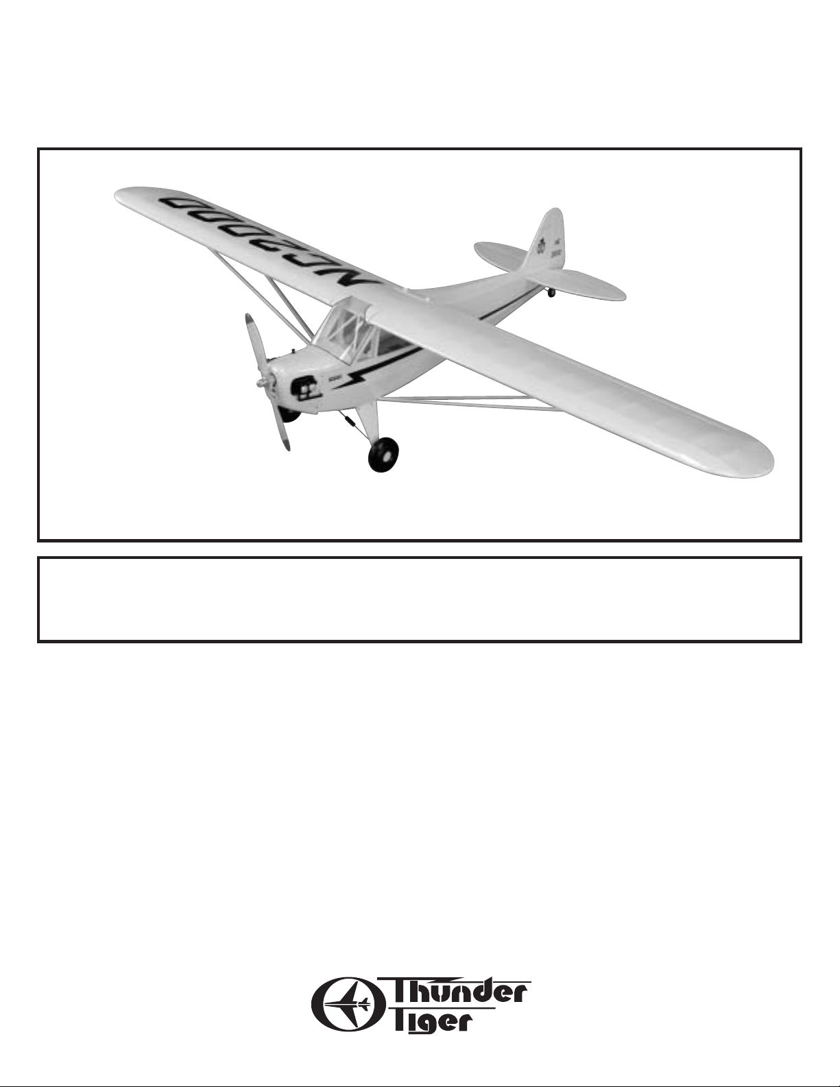
Thunder Tiger Piper J-3 Cub ARF Airplane (TTR4532)
Distributed in North America by Ace Hobby Distributors,Inc.• 116 W 19th ST,Higginsville,MO 64037
Phone:660-584-7121 • www.acehobby.com • E-mail:acehobby@ctcis.net
Piper J-3 Cub
Assembly Manual
Wingspan: 82.7” (2100mm)
Length: 48” (1215mm)
Wing area: 850 in2(55dm2)
Weight: 6.5-7.5lbs (3-3.5kg)
Engine: .46-.61 2 Cycle
.50-.91 4 Cycle
Radio: 4 Channel (5 Servos)
Specifications:
Warranty
This kit is guaranteed to be free from defects in material and workmanship at the date of purchase.
It does not cover any damage caused by use or modification. The warranty does not extend beyond the
product itself and is limited only to the original cost of the kit. By the act of building this user-assembled
kit,the user accepts all resulting liability for damage caused by the final product. If the buyer is not
prepared to accept this liability,it can be returned new and unused to the place of purchase for a refund.
99206/JE6120
Notice: Adult Supervision Required
This is not a toy. Assembly and f lying of this product requires adult supervision.
Read through this book completely and become familiar with the assembly and f light of this airplane.
Inspect all parts for completeness and damage. If you encounter any problems,call 660-584-6724 for help.
Page 2

2
INTRODUCTION
PRE-ASSEMBLY NOTES
One of the most recognized names in aviation history is the Piper J-3 Cub. A child of the Depression,
Mr.Piper’s Cub began production in the early ‘30s,evolving into the 65 HP J-3 version in 1939. Proliferating
in the years before and during WWII,the Cub has introduced more young men to the joys of flight than any
other airplane ever.
Now you can own a part of aviation’s history and enjo y the relaxing and realistic f light characteristics of
the venerable J-3 Cub. Thunder Tiger’s ARF J-3 has been meticulously built from the finest material and covered with UltraCote® in the classic Cub Yellow color scheme. Scale details such as wing struts, landing gear
bungees,Cub wheels,accurately contoured fuselage,and dummy engine cylinder heads create a headturning beauty. Only a few hours of enjoyable assembly and you are ready to step back in time and be a
part of history b y flying the classic,IMAA legal J-3 Cub.
Before beginning the assembly read the instructions thoroughly to give an understanding of the
sequence of steps and a general awareness of the recommended assembly procedures.
By following these instructions carefully and referring to the corresponding pictures,the assembly of
your model will be both enjoyable and rewarding. The result will be a well built,easy to assemble A.R.F.
model,which you will be proud to display and also provide you flying excitement not unlike its full-scale
counterpart.
If you are not an experienced R/C pilot,plan to have a fully competent pilot check your completed
model and help you with your first flights. Even though we have tried to provide you with a very thorough
instruction manual,R/C models are rather complicated and an experienced modeler can quickly check over
your model to help make sure your first flights are successful. Your J-3 Cub is designed for intermediate to
advanced pilots.
Before you begin,check the entire contents of your kit
against the parts list and photos to make sure that no parts
are missing or damaged. This will also help you to become
familiar with each component of your plane. If you find
that any of the parts are either missing or damaged,please
contact Ace Hobby Distributors,Inc.,Customer Service
(660-584-6704) immediately for replacements.
Note: Neither your dealer nor
Ace Hobby Distributors, Inc., can accept
kits for return if construction has begun.
Trial fit each part before gluing it in place. Make sure
you are using the correct part and that it fits well before
assembling. No amount of glue can make up for a poorfitting part.
Introduction
@@@?f
@@@?f
@@@?f
@@@?f
@@@?f
@@@?f
@@@?f
@@@?f
@@@?f
@@@?f
@@@?f
@@@?f
@@@?f
@@@?f
@@@?f
@@@?f
@@@?f
@@@?f
@@@?f
@@@?f
@@@?f
@@@?f
@@@?f
@@@?f
@@@?f
@@@?f
@@@?f
@@@?f
@@@?f
@@@?f
@@@?f
@@@?f
@@@?f
@@@?f
@@@?f
@@@?f
@@@?f
@@@?f
@@@?f
2
Other Items Required
@@@?f
@@@?f
@@@?f
@@@?f
@@@?f
@@@?f
@@@?f
@@@?f
@@@?f
@@@?f
@@@?f
@@@?f
@@@?f
@@@?f
@@@?f
@@@?f
@@@?f
@@@?f
@@@?f
@@@?f
@@@?f
@@@?f
@@@?f
@@@?f
@@@?f
@@@?f
@@@?f
2
Items Needed Check List
@@@?f
@@@?f
@@@?f
@@@?f
@@@?f
@@@?f
@@@?f
@@@?f
@@@?f
@@@?f
@@@?f
@@@?f
@@@?f
@@@?f
@@@?f
@@@?f
@@@?f
@@@?f
@@@?f
@@@?f
@@@?f
@@@?f
@@@?f
@@@?f
3
Parts Sketches
@@@?f
@@@?f
@@@?f
@@@?f
@@@?f
@@@?f
@@@?f
@@@?f
@@@?f
@@@?f
@@@?f
@@@?f
@@@?f
@@@?f
@@@?f
@@@?f
@@@?f
@@@?f
@@@?f
@@@?f
@@@?f
@@@?f
@@@?f
@@@?f
@@@?f
@@@?f
@@@?f
@@@?f
@@@?f
@@@?f
@@@?f
@@@?f
@@@?f
@@@?f
@@@?f
@@@?f
4-5
Wing Assembly
@@@?f
@@@?f
@@@?f
@@@?f
@@@?f
@@@?f
@@@?f
@@@?f
@@@?f
@@@?f
@@@?f
@@@?f
@@@?f
@@@?f
@@@?f
@@@?f
@@@?f
@@@?f
@@@?f
@@@?f
@@@?f
@@@?f
@@@?f
@@@?f
@@@?f
@@@?f
@@@?f
@@@?f
@@@?f
@@@?f
@@@?f
@@@?f
@@@?f
6-9
Fuselage Assembly
@@@?f
@@@?f
@@@?f
@@@?f
@@@?f
@@@?f
@@@?f
@@@?f
@@@?f
@@@?f
@@@?f
@@@?f
@@@?f
@@@?f
@@@?f
@@@?f
@@@?f
@@@?f
@@@?f
@@@?f
@@@?f
@@@?f
@@@?f
@@@?f
@@@?f
@@@?f
@@@?f
10-12
Stabilizer Assembly
@@@?f
@@@?f
@@@?f
@@@?f
@@@?f
@@@?f
@@@?f
@@@?f
@@@?f
@@@?f
@@@?f
@@@?f
@@@?f
@@@?f
@@@?f
@@@?f
@@@?f
@@@?f
@@@?f
@@@?f
@@@?f
@@@?f
@@@?f
@@@?f
@@@?f
@@@?f
@@@?f
12-14
Engine & Fuel Tank Installation
@@@?f
@@@?f
@@@?f
@@@?f
@@@?f
@@@?f
@@@?f
@@@?f
@@@?f
@@@?f
@@@?f
@@@?f
14-15
Radio Installation
@@@?f
@@@?f
@@@?f
@@@?f
@@@?f
@@@?f
@@@?f
@@@?f
@@@?f
@@@?f
@@@?f
@@@?f
@@@?f
@@@?f
@@@?f
@@@?f
@@@?f
@@@?f
@@@?f
@@@?f
@@@?f
@@@?f
@@@?f
@@@?f
@@@?f
@@@?f
@@@?f
16-18
Cowl Installation
@@@?f
@@@?f
@@@?f
@@@?f
@@@?f
@@@?f
@@@?f
@@@?f
@@@?f
@@@?f
@@@?f
@@@?f
@@@?f
@@@?f
@@@?f
@@@?f
@@@?f
@@@?f
@@@?f
@@@?f
@@@?f
@@@?f
@@@?f
@@@?f
@@@?f
@@@?f
@@@?f
@@@?f
@@@?f
@@@?f
@@@?f
@@@?f
@@@?f
19
Windshield Installation
@@@?f
@@@?f
@@@?f
@@@?f
@@@?f
@@@?f
@@@?f
@@@?f
@@@?f
@@@?f
@@@?f
@@@?f
@@@?f
@@@?f
@@@?f
@@@?f
@@@?f
@@@?f
@@@?f
@@@?f
@@@?f
@@@?f
@@@?f
@@@?f
@@@?f
@@@?f
@@@?f
20
Wing Strut Attachment
@@@?f
@@@?f
@@@?f
@@@?f
@@@?f
@@@?f
@@@?f
@@@?f
@@@?f
@@@?f
@@@?f
@@@?f
@@@?f
@@@?f
@@@?f
@@@?f
@@@?f
@@@?f
@@@?f
@@@?f
@@@?f
20-21
Balance
@@@?f
@@@?f
@@@?f
@@@?f
@@@?f
@@@?f
@@@?f
@@@?f
@@@?f
@@@?f
@@@?f
@@@?f
@@@?f
@@@?f
@@@?f
@@@?f
@@@?f
@@@?f
@@@?f
@@@?f
@@@?f
@@@?f
@@@?f
@@@?f
@@@?f
@@@?f
@@@?f
@@@?f
@@@?f
@@@?f
@@@?f
@@@?f
@@@?f
@@@?f
@@@?f
@@@?f
@@@?f
@@@?f
@@@?f
@@@?f
@@@?f
@@@?f
@@@?f
@@@?f
@@@?f
21
Control Thro ws
@@@?f
@@@?f
@@@?f
@@@?f
@@@?f
@@@?f
@@@?f
@@@?f
@@@?f
@@@?f
@@@?f
@@@?f
@@@?f
@@@?f
@@@?f
@@@?f
@@@?f
@@@?f
@@@?f
@@@?f
@@@?f
@@@?f
@@@?f
@@@?f
@@@?f
@@@?f
@@@?f
@@@?f
@@@?f
@@@?f
@@@?f
@@@?f
@@@?f
21
Flying Hints
@@@?f
@@@?f
@@@?f
@@@?f
@@@?f
@@@?f
@@@?f
@@@?f
@@@?f
@@@?f
@@@?f
@@@?f
@@@?f
@@@?f
@@@?f
@@@?f
@@@?f
@@@?f
@@@?f
@@@?f
@@@?f
@@@?f
@@@?f
@@@?f
@@@?f
@@@?f
@@@?f
@@@?f
@@@?f
@@@?f
@@@?f
@@@?f
@@@?f
@@@?f
@@@?f
@@@?f
@@@?f
@@@?f
@@@?f
22
Pre-Flight Checks
@@@?f
@@@?f
@@@?f
@@@?f
@@@?f
@@@?f
@@@?f
@@@?f
@@@?f
@@@?f
@@@?f
@@@?f
@@@?f
@@@?f
@@@?f
@@@?f
@@@?f
@@@?f
@@@?f
@@@?f
@@@?f
@@@?f
@@@?f
@@@?f
@@@?f
@@@?f
@@@?f
@@@?f
@@@?f
@@@?f
@@@?f
@@@?f
@@@?f
22
Safety Precautions
@@@?f
@@@?f
@@@?f
@@@?f
@@@?f
@@@?f
@@@?f
@@@?f
@@@?f
@@@?f
@@@?f
@@@?f
@@@?f
@@@?f
@@@?f
@@@?f
@@@?f
@@@?f
@@@?f
@@@?f
@@@?f
@@@?f
@@@?f
@@@?f
@@@?f
@@@?f
@@@?f
@@@?f
@@@?f
@@@?f
22
Post-FlightCheck List
?
?
?
?
?
?
?
?
?
?
?
?
?
?
?
?
?
?
?
?
?
?
?
@@@?e?
@@@?e?
@@@?e?
?
?
?
?
?
?
?
?
?
?
?
?
?
?
?
?
?
?
?
?
?
?
?
?
?
?
?
?
?
?
?
?
?
?
?
@@@?e?
@@@?e?
@@@?e?
?
?
?
?
?
?
?
?
?
?
?
?
?
?
?
?
?
?
?
?
?
?
?
?
?
?
?
?
?
?
?
?
?
?
?
@@@?e?
@@@?e?
@@@?e?
?
?
?
?
?
?
?
?
?
?
?
?
?
?
?
?
?
?
?
?
?
?
?
?
?
?
?
?
?
?
?
?
?
?
?
@@@?e?
@@@?e?
@@@?e?
?
?
?
?
?
?
?
?
?
?
?
?
?
?
?
?
?
?
?
?
?
?
?
?
?
?
?
?
?
?
?
?
?
?
?
@@@?e?
@@@?e?
@@@?e?
?
?
?
?
?
?
?
?
?
?
?
?
?
?
?
?
?
?
?
?
?
?
?
?
?
?
?
?
?
?
?
?
?
?
?
@@@?e?
@@@?e?
@@@?e?
?
?
?
?
?
?
?
?
?
?
?
?
?
?
?
?
?
?
?
?
?
?
?
?
?
?
?
?
?
?
?
?
?
?
?
@@@?e?
@@@?e?
@@@?e?
?
?
?
?
?
?
?
?
?
?
?
?
?
?
?
?
?
?
?
?
?
?
?
?
?
?
?
?
?
?
?
?
?
?
?
@@@?e?
@@@?e?
@@@?e?
?
?
?
?
?
?
?
?
?
?
?
?
?
?
?
?
?
?
?
?
?
?
?
?
?
?
?
?
?
?
?
?
?
?
?
@@@?e?
@@@?e?
@@@?e?
?
?
?
?
?
?
?
?
?
?
?
?
?
?
?
?
?
?
?
?
?
?
?
?
?
?
?
?
?
?
?
?
?
?
?
@@@?e?
@@@?e?
@@@?e?
?
?
?
?
?
?
?
?
?
?
?
?
22
TABLE OF CONTENTS
Page 3
3
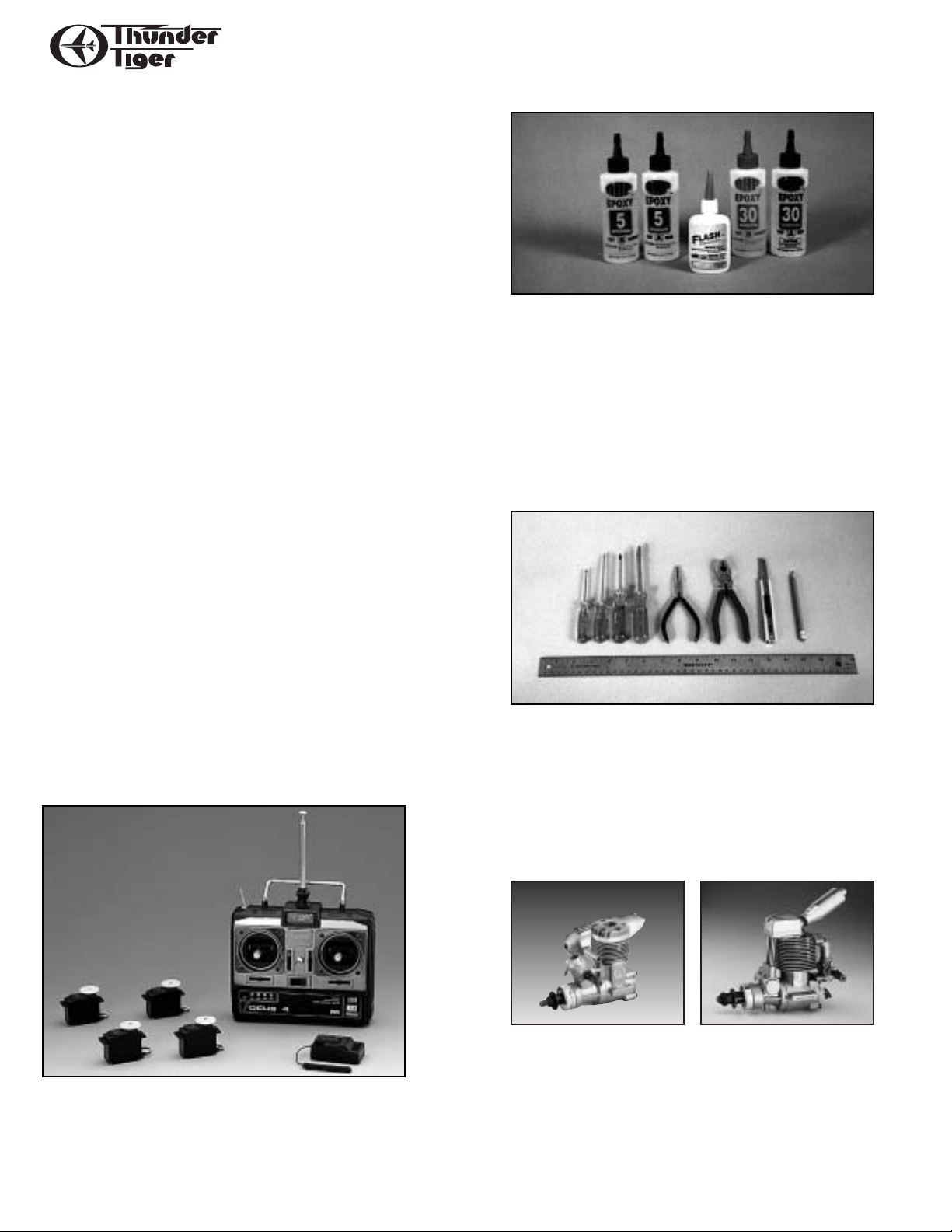
RECOMMENDED TOOLS & MATERIALS
Adhesives:
Instant setting Cyanoacrylate adhesive (thin CA)
Slow setting Cyanoacrylate adhesive (thick CA)
10 Minute Epoxy (fast)
20-30 Minute Epoxy (slow)
R/C 56 Glue
Tools:
Model knife,T-Pins,1/2”vinyl tape
Small screwdrivers,Medium screwdrivers
Scissors
Steel straight edge
Long nose pliers and diagonal cutting pliers
Drill and drill bits
Sanding block
Fine felt tip pen and soft lead pencil
Straight building board
R/C System:
4 Channel radio with 5 servos
Engine:
2 cycle: .40 to .61 CID
4 cycle: .50 to .91 CID
Propeller (appropriate for engine type and
preferred performance)
Adhesives - You will need two types of adhesives
for the Fun Tiger - Epoxy and Instant (cyanoacrylate)
adhesives. We recommend that you purchase both
5-minute and 30-minute epoxy to cut down on
assembly time, but you can get by with only 30minute epoxy if time is not important. You will also
need a small bottle of both “Thick” and “Thin”
instant adhesive.
Tools - Model assembly can be much easier if the
proper tools are used. Therefore, we have included
in our checklist to the left, a complete listing of all
the tools we used to assemble our prototype models.As you will notice, many household tools can be
utilized during construction.
Engine - The Thunder Tiger PRO-46 and F-54S are
the ideal engines for this airplane.These quiet-running engines are easy to start, require no special
break-in periods, are very easy to maintain and will
last for years.
Radio - A 4-channel radio with five standard servos
is required.
Page 4
4
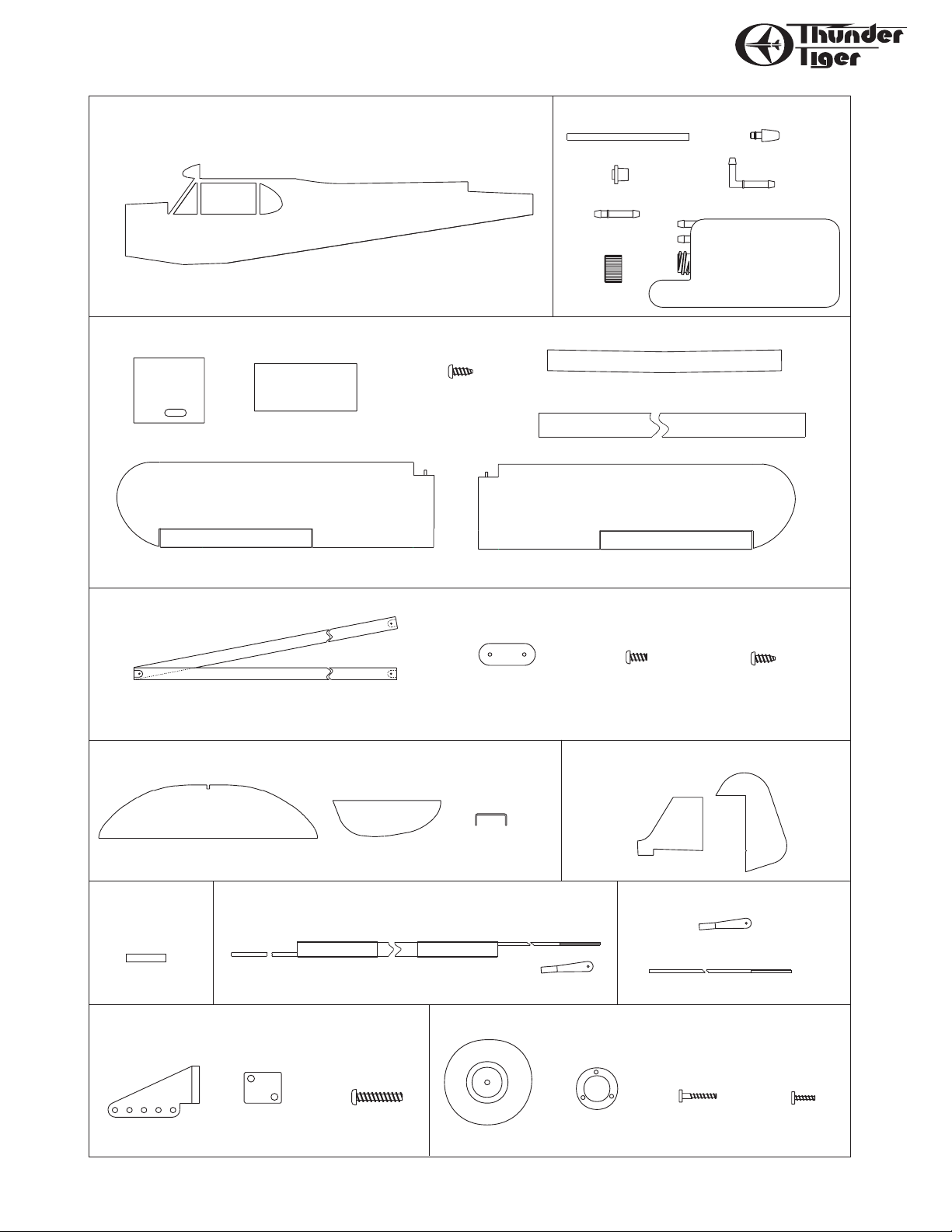
PARTS DRAWINGS
AS6034
Back Plate (2) Screw (6)
Vertical Fin (1) Rudder (1)
Vertical Tail AS6033
Stabilizer (1) Elevator (2) Elevator Joiner (1)
1/8" Wire
Horizontal Tail AS6032
M3mm x 8mm
Tapping Screw (6)
M3mm x 5mm
Screw (6)
M2mm x 8mm
Screw (8)
Control Horn (2)
M2mm x 15mm
Screw (4)
Control Horn Set #3151
M2mm X 6mm
Screw (6)
M2mm X 3mm
Fuselage AS6029
Fuselage(1)
Stab/Rudder Pushrods(2)
Clevis (2)
Clevis (2)
Left Wing (1)
Wing AS6030
Right Wing (1)
Trim Tape (1)
Shrink tube (4)
Aft Pushrods AS6035
Threaded Rod (2)
Aileron Pushrods #3152
Main Wheels (2) Hub Cover(2)
Wing Bolt Plate (1)
Wing Joiner (3)
Shrink tube
Main wheel #3101
Mounting Plate (6)Wing Struct (2)
Hatch (2)
Wing Struct AS6031
Silicone Tube (1)
Cap (1)
Fuel Stopper (1)
Nipple (1)
300 c.c. Tank (1)
90" Nipple (1)
Fuel Tank Set #3263
Clunk (1)
Page 5
5
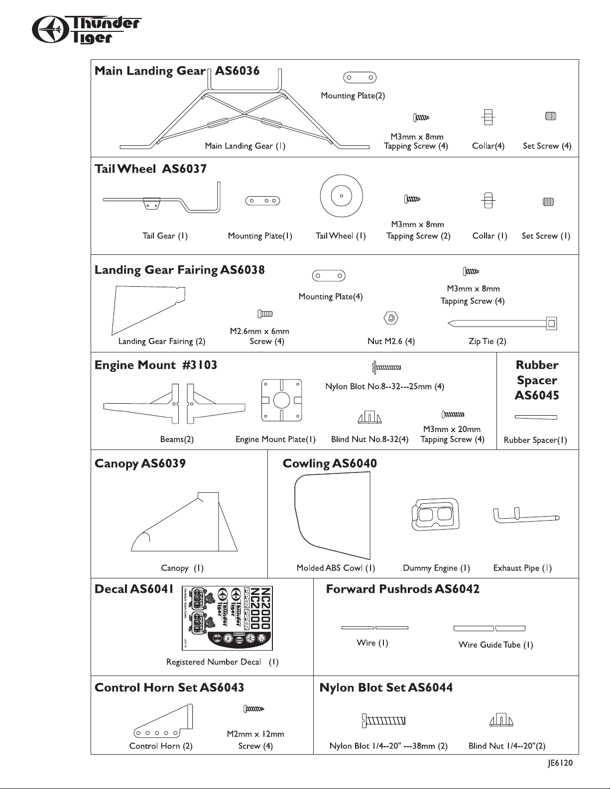
PARTS DRAWINGS
Page 6
6
WING ASSEMBLY
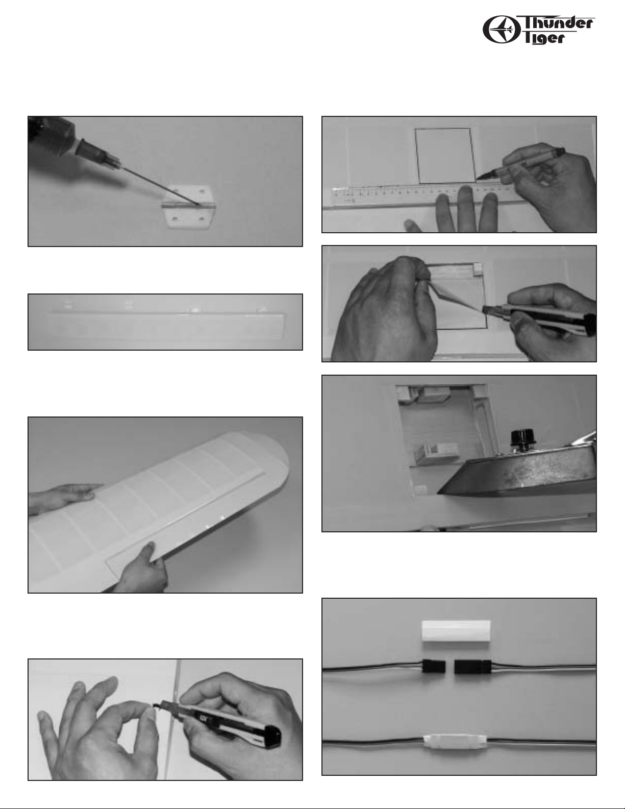
❐ With the right wing panel once again upside down on the building
board,determine the aileron servo location (2nd wing bay in from the
inboard edge of the aileron). Using a felt tip pen,draw a cutting line
3/16” inside the bay. Carefully cut away the covering and seal the
edges using a heating iron.(Photos 5, 6 & 7)
❐ Obtain two servo extensions that give you the necessary lead
length for your aileron servos (12”or so). Join the aileron servo and
servo extension. Cover the connection with heat shrink tubing provided and using a heat gun shrink the tubing over the connectors.
(Photo 8).
❐ Identify the right and left wing panels. Carefully remove the tape
that temporarily secures the ailerons to each wing panel.
❐ Carefully remove all hing es from the ailerons and appl y a small drop
of oil to each hinge on the hinge pin.(Photo 1)
❐ Apply 20-30 Minute Epoxy to one half of each hinge and insert into
the right aileron. Set aside to cure and repeat procedure for the left
aileron.(Photo 2)
❐ Apply 20-30 Minute Epoxy to the exposed portion of the hinges on
the right aileron. Carefully fit the aileron into the right wing panel.
Wipe off any excess epoxy using denatured (rubbing) alcohol. Set
aside to cure. Repeat the same procedure for the left wing aileron and
wing panel.(Photo 3)
❐ Place the right wing panel upside down on the building board.
Locate the exit hole for the aileron extension. Using a model knife,
carefully cut and remove the cov ering material covering the e xit hole.
Repeat the procedure for the left wing panel. (Photo 4)
Photo 1
Photo 2
Photo 3
Photo 4
Photo 8
Photo 7
Photo 6
Photo 5
Page 7
7
WING ASSEMBLY
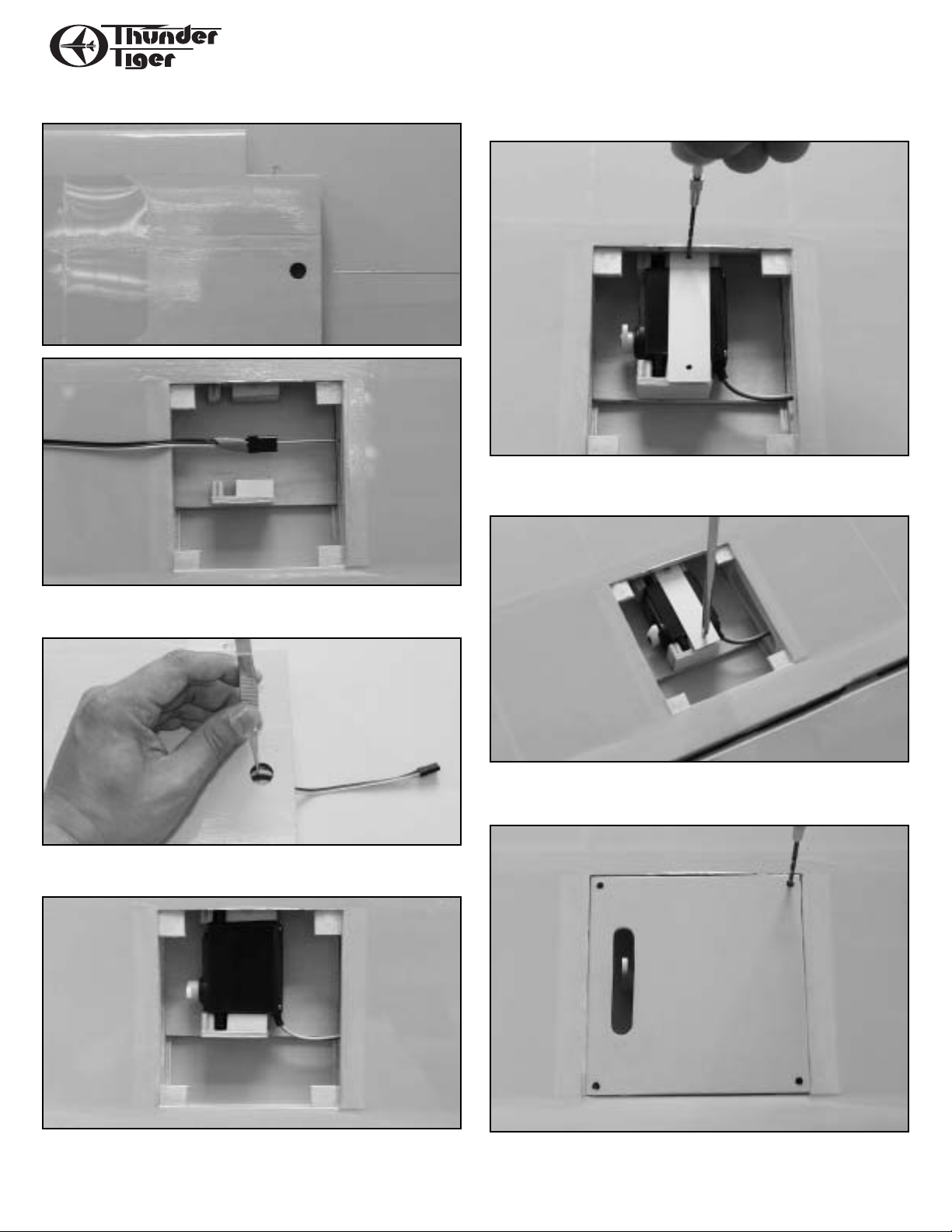
❐ Insert a piece of piano wire through the root rib of the wing panel
and “fish”the aileron servo lead through the wing.(Photos 9 & 10)
❐ Use a pair of tweezers to pull the servo lead through the exit hole
in the wing panel (Photo 11).
❐ Place the servo in the wing panel in the servo mount. (Photo 12)
❐ Place the servo hold down plate over the servo and drill through
the plate into the servo mount taking caution not to drill through the
wing.(Photo 13)
❐ Using M2.5X8 wood screws,screw the servo hold down plate in
place (Photo 14)
❐ Locate the correct servo cover and install in the right wing panel.
❐ Drill 4 3/64”holes at the four corners. (Photo 15)
Photo 9
Photo 10
Photo 11
Photo 12
Photo 15
Photo 14
Photo 13
Page 8
8
WING ASSEMBLY
❐ Place the control horn on the aileron and align with the servo
horn slot in the hatch cover. Dr ill holes using the control horn as a
template. Secure the control horn with two M2x12 screws and the
backer plate. (Photo 16)
❐ Locate the control clevis and thread onto the push rod. Snap the
clevis onto the control with the servo at the neutral position. Mark the
clevis for the “Z” bend. (Photo 17)
❐ Remove the clevis,cut of f the excess wire and insert the “Z”bend
through the hatch cover then into the servo horn. Snap the clevis
onto the control horn. Secure the hatch cover with 4 M2x8 wood
screws. (Photos 18 & 19)
❐ Repeat the above procedures for the left wing panel.
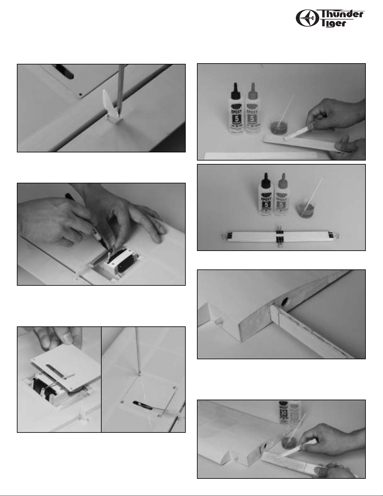
❐ Locate the three wing joiners (2 plywood and 1 aluminum). Apply
a coat of 5-10 Minute Epoxy to each side of the aluminum joiner and
mate the 2 plywood joiner to it. Clamp the assembly together and set
aside to cure. (Photos 20 & 21)
❐ Draw a center line on the wing joiner and trial fit into the spar box
on each wing panel. Sand to fit as necessar y. (Photo 22)
❐ When the two wing panels match up perfectly, apply 30-45 Minute
Epoxy to the wing joiner on one half only. Liberally apply 30-45
Minute Epoxy to the spar box in the right wing panel. Insert the joiner into the spar box wiping off any excess epoxy. Set aside to cure.
(Photo 23)
Photo 16
Photo 18
Photo 19
Photo 23
Photo 22
Photo 21
Photo 20
Photo 17
SUGGESTION: Secure any clevis/control horn connection with a
piece of medium fuel tubing about 1/4”long. (Not Shown)
Page 9

9
WING ASSEMBLY
❐ Apply 30-45 Minute Epoxy to the left wing panel spar box as well
as the entire root rib. Carefully join the two wing panels together.
Wipe off any excess epoxy. Block up each wing tip 5/8”and allow to
cure. It may be necessary to use masking tape to hold the wing panels in position until cured.Photo 24)
❐ Use the hardwood wing bolt plate as a template. Draw a reference
line on the top of the wing at the trailing edge. Using a hobby knife
carefully cut the covering and remove from the wing. Use caution not
to cut into the wing skin. (Photo 25)
❐ Using 5-10 Minute Epoxy,glue the hardwood wing bolt plate into
place. Locate and mark a reference point 5/8”in from each side and 13/8”up from the trailing edge of the wing.Using a 9/32” (7mm) drill,
drill a hole through the wing at each reference mark.(Photo 26)
❐ Place the wing on the fuselage. Carefully align the wing ensuring
that it is centered on the fuselage. Using a 19/64” (7.4mm) drill bit,
drill through the wing into the wing hold down plate in the fuselage
using the previously drilled holes as a reference.(Photo 27)
❐ Remove the wing from the fuselage. Install the blind nuts in the
bottom of the wing hold down mounting plate. Install the wing hold
screws in the blind nuts and pull up tightly ensuring that the blind
nuts are secured in place.(Photo 28)
❐ Remove the wing bolts and trial mount the wing to the fuselage.
Adjust as necessary to ensure proper alignment.(Photo 29)
❐ Remove the wing and cover the center joint with the trim covering provided.
Photo 24
Photo 25
Photo 26
Photo 27
Photo 28
Photo 29
Page 10

10
FUSELA GE ASSEMBL Y
❐ Carefully cut away the covering over the landing gear slot on the
bottom of the fuselage.(Photo 30)
❐ Position the preformed landing gear in place. Locate the landing
gear retaining plates (2) and place them over the landing gear. Using
a felt tip pen mark the location for the mounting screws.(Photo 31)
❐ Remove the landing gear and drill 4 5/64”(2mm) holes.(Photo 32)
❐ Reinstall the landing gear and secure it in place with 4 M3x8 wood
screws.(Photo 33)
❐ Locate the Cub Wheels and secure the hub in place with the
provided screws.(Photo 34)
❐ Insert a 5mm-wheel collar (w/set screw) onto the landing gear.
Do not tighten at this time (Photo 35)
Photo 30
Photo 31
Photo 32
Photo 35
Photo 34
Photo 33
Page 11

11
FUSELA GE ASSEMBL Y
❐ Install the Cub Wheel followed by another 5mm-wheel collar.
Ensure that the wheel collar is even with the edge of the landing gear
axle and secure it in place with the “L”wrench provided.(Photo 36)
❐ Place the hubcap on the Cub Wheel and mount it in place with the
small screws provided. Secure the or iginal wheel collar against the
back of the Cub Wheel allowing freedom of motion without being too
loose.(Photo 37)
❐ Locate the pre-covered landing gear fairings. Drill 2 7/64”(2.6mm)
holes as shown. (Photo 38)
❐ Carefully bend the mounting plates to a 45-degree angle then
secure to the fairings with M2.6x6 screws and M2.6 nuts.(Photo 39)
❐ Hold the landing gear fairing in place. Using a felt tip pen mark the
location on the fuselage for the mounting screw. Ensure that the landing gear fairing is located underneath the bottom/corner of the fuselage.(Photo 40)
❐ Drill 5/64”(2mm) holes at the marked locations.(Photo 41)
Photo 36
Photo 37
Photo 38
Photo 41
Photo 40
Photo 39
Page 12

12
FUSELA GE ASSEMBL Y/STABILIZER ASSEMBLY
❐ Mount the landing gear fairings in place using 4 M3x8 wood
screws.(Photo 42)
❐ Secure the lower portion of the landing gear fairings to the landing
gear using the small nylon tie wraps provided. (Photo 43)
❐ Locate both elevator halves. Carefully cut away the covering on the
elevators where the wire elevator joiner is to be installed (Photo 44)
❐ Attach the elevator joiner wire to each elevator half with thick CA
or 5 minute epoxy.(Photo 45)
❐ Remove the hinges from the horizontal stabilizer and apply a drop
of oil to each hinge. Apply 10-20 minute epoxy to one side of each
hinge and install in each elevator half. Set aside to cure.(Photo 46)
❐ Apply 10-20 minute epoxy to the hinges on the elevators and install
them on the horizontal stabilizer. Allow curing then cut a notch in the
covering at the center leading edge for the vertical stabilizer.
(Photo 47)
❐ At the rear of the fuselage locate the positions for the horizontal
and vertical stabilizers. Using a hobby knife carefully cut away the
covering over these areas. (Photo 48)
STABILIZER ASSEMBLY
Photo 42
Photo 45
Photo 46
Photo 43
Photo 44
Photo 47
Photo 48
Page 13

13
STABILIZER ASSEMBLY
❐ Temporarily install the horizontal and vertical stabilizers (in that
order). Using a felt tip pen mark the fuselage location on both the
horizontal and vertical stabilizers. (Photo 49)
❐ Remove the horizontal and vertical stabilizers from the fuselage.
Using a hobby knife cut the covering along the marked lines being
careful not to cut in the wood which could result in structural failure.
(Photo 50)
❐ Mount the wing to the fuselage. Using 30-45 minute epoxy,install
the horizontal and vertical stabilizers in position. Ensure that the horizontal stabilizer is parallel with the wing and that the vertical stabilizer is 90-degrees to the horizontal stabilizer. Set aside until cured.
❐ Locate the tail wheel wire hole on the rudder.Cut a slot in the fuselage for the tail wheel gear wire hinge.(Photo 51)
❐ Cut a slot on the leading edge of the rudder. Trial fit the tail wheel
gear wire to the rudder. Cut a notch in the leading edge of the rudder
to allow clearance for the elevator joiner wire (Photo 52)
❐ Locate the hinges for the rudder and place a drop of oil on each
hinge joint. Using 10-20 minute epoxy apply epoxy to one side of the
hinges and install them into the rudder . Install the tail wheel gear wire
into the rudder at this time also using epoxy. Set aside until cured.
(Photo 53)
❐ Apply 10-20 minute epoxy to the hinges and install the rudder and
tail wheel gear wire into the vertical stabilizer and fuselage respectively. Press together as tightly as possible to ensure minimal gap
between the rudder and vertical stabilizer. Install the tail wheel
mounting plate as shown with 2 M3x8 wood screws.(Photo 54).
Photo 51
Photo 54
Photo 53
Photo 50
Photo 49
Photo 52
Page 14

14
STABILIZER ASSEMBLY ENGINE & FUEL TANK INST.
❐ Install the tail wheel and secure in place with the provided wheel
collar. (Photo 55)
❐ Locate the elevator control horn on the right elevator with the
clevis holes in line with the hinge line. Drill 2 5/64”(2mm) holes using
the control horn base as a template. Secure the elevator control horn
to the elevator using 2 M2x15 screws and the control horn backplate.
(Photo 56)
❐ Using the same procedure as for the elevator control horn,install
the rudder control on the left side of the rudder. (Photo 57)
❐ Locate the rubber spacer and adjustable engine mount. Hold in
place on the fuselage firewall and verify fit. Mount the rubber spacer
and engine mount to the firewall but do not secure it in place at this
time.(Photo 58)
❐ Assemble the fuel tank as shown taking care to insure that the fuel
tank clunk is not restricted in motion.(Photo 59)
❐ Cut three 6-8”pieces of standard fuel tubing to length. Install them
on the fuel tank nipples and install the fuel tank in the fuel tank com-
partment. Note that it is easier to feed the lines through the firewall
if they are tied together with a piece of line and pulled through.
(Photo 60)
❐ Secure the tank in place with small foam blocks or foam rubber.
(Photo 61)
Photo 55
Photo 56
Photo 57
Photo 60
Photo 59
Photo 58
Photo 61
Page 15

15
ENGINE & FUEL TANK INSTALLATION
❐ Install the throttle push-rod tube through the firewall and into the
radio compartment. (Photo 62)
❐ Leave approximately 1/4”of the push-rod tube extending into the
engine compartment. Epoxy in place. (Photo 63)
❐ Place the engine on the adjustable motor mount and locate the
front drive hub 4-13/16” from the firewall. Mark the mounting hole
locations on the motor mount.(Photo 64)
❐ Remove the engine and drill a 5/64” (2mm) hole at each of the
marks. (Photo 65)
❐ Secure the engine to the motor mount using the 4 M3x20 self-tap-
ping screws provided.Secure the adjustable engine mount at this time
and make sure there is 2-degree right thrust angle.(Photo 66)
❐ If installing the recommended Thunder Tiger F-54S engine,extend
the choke valve wire insuring that it is long enough to clear the cowl-
ing. (Photo 67)
Photo 65
Photo 62
Photo 63
Photo 66
Photo 64
Photo 67
Page 16

16
RADIO INSTALLATION
❐ Install the switch harness as shown. Wrap the battery pack in foam
and install underneath the fuel tank (Photo 68). You may have to
adjust the battery location to obtain the proper CG.
❐ Locate the antenna guide tube exit at the rear of the fuselage on
the bottom and remove the covering around the exit hole using a
hobby knife (Photo 69).
❐ Insert the receiver antenna through the guide tube located under
the servo tray.Leave approximately 2”(5cm) of the antenna extending
outside the exit (Photos 70 & 71).
❐ Install the three servos in the radio compartment (throttle,rudder,
and elevator). From the tail facing forward from right to left, the servos are throttle,rudder and elevator. Plug the servos into the receiver
and set neutral.(Photo 72)
❐ Install the EZ connector on the throttle servo horn. Place the servo
horn on the servo (Photo 73).
❐ Remove the throttle lever from the engine. Make a “Z”bend at one
end of the push rod and install it on the throttle lever (Photo 74).
Photo 68
Photo 69
Photo 70
Photo 71
Photo 74
Photo 73
Photo 72
Drill a 1/16” hole
in switch lever.
See Step 85.
Page 17

17
RADIO INSTALLATION
❐ Install the other end of the throttle push rod in the EZ connector.
Trim off any excess wire (Photo 75).
❐ Using a hobby knife carefully cut away the covering over the elevator and rudder push-rod exits at the rear of the fuselage (Photo 76).
❐ Install one push rod with the threaded end first through the fuselage and exiting at the elevator exit slot. Locate a clevis and thread it
onto the threaded end at least 20 turns. Snap the clevis onto the control horn at the 3rd hole from the bottom (Photo 77).
❐ Mark the other end of the push rod where the “Z” bend is to be
located (Photo 78).
❐ Using “Z”Bend Pliers bend the push rod at the location marked
(Photo 79).
❐ Insert the “Z”bend into the servo horn. Install the ser vo horn on
the servo (Photo 80).
Photo 77
Photo 76
Photo 75
Photo 78
Photo 79
Photo 80
Page 18

18
RADIO INSTALLATION
❐ Install the rudder push rod using the same steps as for the elevator.
(Photos 81,82,and 83)
Using a piece of the excess wire bend an extension for the on-off
switch.(Photo 84)
❐ Drill a small hole through the fuselage in line with the switch.
Insert the extension wire through the fuselage and place in the switc h.
Using needle nose pliers bend the wire to prevent it from coming
loose.(Photos 85 & 86)
❐ Measure the cowl for the engine to be used and trim the cowling
to fit your particular engine.Cut all the inlets along the molded lines.
(Photo 87)
Photo 81
Photo 82
Photo 83
Photo 84
Photo 87
Photo 86
Photo 85
Page 19

19
COWL INSTALLATION
❐ You may need to make a cut behind the engine cylinder head to
allow the cowling to go into place with minimal effort.(Photo 88)
❐ With the cowl in position cut a hole for the needle valve and route
the fuel line out of the cowling (Photo 89).
❐ Install the header pipe and muffler (Photo 90).
❐ Position the cowl and drill 3 1/16” (1.5mm) holes on both sides
(Photo 91).
❐ Secure the cowl with 6 M2.5x8 wood screws. Route fuel lines from
the cowl. One is the fuel filler line and the other goes to the muffler
pressure fitting. The final line is from the engine breather fitting
(4-cycle) and vents via a piece of aluminum tubing held in place on the
muffler with small tie wraps (Photo 92).
❐ Install the dummy cylinders to the right side of the cowling using
R/C 56 glue. Paint the valve covers silver (Photo 93).
Photo 89
Photo 90
Photo 91
Photo 92
Photo 93
Photo 88-2
Photo 88-1
Page 20

20
WINDSHIELD INSTALLATION WING STRUT ATTACHMENT
❐ Cut the windshield along the molded cutting line using a pair of
scissors (Photo 94).
❐ Using black and yellow paint,paint the windshield as shown
(Photo 95).
❐ Attach the windshield to the fuselage. Hold the windshield in place
with masking tape. Apply R/C 56 glue along the area where the windshield meets the fuselage. Allow to cure over night (Photo 96).
❐ Cut a notch in the wing strut at each end.Drill a 5/64”(2mm) hole
at the wing strut notch (Photo 97).
❐ Secure the mounting plate as shown with a M3x5 wood screw
(Photo 98).
❐ Refer to Photo 99. The top strut is for the right wing and the lower
strut is for the left wing.
Photo 99
Photo 98
Photo 97
Photo 94
Photo 95
Photo 96
Page 21

21
WING STRUT ATTACHMENT BALANCE
CONTROL THRO WS
❐ Bend the mount plates that attach to the wing at a 25-degree angle
so that they are flush with the surface of the wing (Photo 100).
❐ Place the strut on the wing locating the hardwood mounting
blocks. Dr ill a 5/64”(2mm) hole at each mounting plate (Photo 101).
❐ Secure the wing strut with 2 M3x8 wood screws (Photo 102).
❐ Place the wing strut on the fuselage directly behind the landing
gear fairing. Mark the position and drill a 5/64” (2mm) hole. Secure
the strut using a M3x8 wood screw (Photo 103).
❐ Repeat the above sequence of steps for the other wing strut.
Apply decals as desired to finish your model.
Center of Gravity location should be between 4 and 4-1/2”back from
the leading edge of the wing. Flying will determine the final balance
point for your particular model.
Make sure that all control surfaces move in the proper direction.
Set the control surface throws as indicated for the initial flights.
These may be altered later for personal preference.
Elevator: Hi Rate: 1-1/4”up, 1-1/4”down
Low Rate: 3/4”up, 3/4”down
Rudder: Hi Rate: Full deflection left and right not
to interfere with elevators
Low Rate: 1”left, 1”right
Aileron: Hi Rate: 1”up, 3/4”down
Low Rate: 3/4”up, 1/2”down
Prior to the first f light ensure that all batteries are properly charged,
that controls all move in the proper direction, and that a thorough
range check is made with and without the engine running.
Photo 100
Photo 101
Photo 102
Photo 103
Page 22

22
PRE-FLIGHT CHECK LIST
❐ 1. Check all control surfaces for possible looseness or deterioration.
❐ 2. Check all screws,clevises,nuts and all other connectors to
make sure they are securely fastened.
❐ 3. Check which radio frequencies are being used. Do not turn
on your radio until absolutely sure you are the onl y one operating on that frequency.
❐ 4. Check for proper operation of all control surfaces.
❐ 5. Check the level of charge in both the transmitter and receiver
batteries before flying.
❐ 6. Range chec k the radio both with and without the engine running!
Follow the radio manufacturers instructions for this.
POST-FLIGHT CHECK LIST
❐ 1. Be sure that both the transmitter and receiver switches are
turned off.
❐ 2. Drain all excess fuel from the tank. Fuel left in the tank for
extended periods can “gunk up”the tank,fittings and carburetor.
❐ 3. Clean the plane with paper towels and a light-duty spray
cleanser. Keeping your plane clean will make it last longer
and keep it looking nice.
❐ 4. Put a few drops of after-run or light oil in the carburetor and
turn the prop over a few times (without the glow plug ignited)
to distribute the oil throughout the engine.
❐ 5. Inspect the prop and replace it if any chips or cracks are found.
❐ 6. Inspect the entire plane for covering tears, new dings and
dents,loose screws and connectors and any other wear and
tear.
SAFETY PRECAUTIONS
1. Wear safety glasses when starting and running all model engines.
2. Model engine fuel is very flammable and the flame is very
dangerous because it is almost invisible! Do not smoke or allow
sparks,high heat or other flames near the fuel.
3. Do not run model engines inside a garage or other closed room as
they give off large amounts of deadly carbon monoxide gas.
4. Do not run model engines around gravel, sand or other loose
debris. These materials will be ingested through the carburetor
and can also be kicked up by the prop.
5. Always stay behind the propeller when the engine is running.
Make all engine adjustments from behind the engine.
6. Do not allow loose clothing or other loose objects c lose to the prop.
7. To stop an engine, cut off the fuel or air supply to the engine.
Do not throw rags or other objects into the prop to stop the
engine.
8. Do not touch the engine or muffler during or right after it has
been running–it gets very hot!
The J-3 Cub is NOT a trainer. We assume you have mastered the
basics of R/C flight. If not, we suggest you learn to fly with a trainer
before attempting flight with the Cub. Thunder Tig er has a larg e selection of Trainers to choose from. Check with your hobby dealer for his
recommendation.
Since your J-3 Cub is a faithful duplicate of its full scale counterpart,we highly recommend that you fly it just like the real thing. You
will find yourself enjoying the airplane considerable more than if you
simply bore holes in the sky. Energy management and minimum airframe stress should be utmost in your mind as you pilot the Cub. Put
yourself in the cockpit and imagine yourself with your hands on the
stick and your feet on the rudder pedals.
TAKEOFF
You will find that your Cub is easy to taxi and the ground handling
is predictable. If it doesn’t track true,you may have to adjust the tail
wheel by bending it a bit using two pairs of pliers.
Since the Cub is a high wing airplane,it is sensitive to crosswind
ground loops. Be prepared with opposite aileron to counter-act crosswind taxiing.
For takeoff,point the plane directly into the wind and gradually
advance throttle while neutalizing the elevator, letting the tail come
up. Increase speed as much as possible before lifting off. Don’t
“horse”the plane off the ground. Remember,f ly it like a real one! A
gental climbout looks much more realistic than a 45 degree “aircraft
carrier”takeoff.
FLYING
Remember, fly your Cub like the real thing. Coordinate turns
using rudder. Keep the maneuvers gentle, big, and graceful. Do your
turnarounds with a gentle stall-turn. Remember,keep energy management and minimal airframe stress in mind at all time.
NEVER,NEVER do full throttle snap-rolls. Keep your Cub in one
piece.
LANDING
Since the Cub has a high lift and lightly loaded wing,it’s a floater.
There are times you will wish you had an anchor to throw out to get
this plane down. Use the largest diameter,lowest pitch prop you can
to get as much prop disc drag as you can.
In wind, the safest way is to keep some power on and plant the
main gear wheels in a two point landing; use the ground drag to slow
the plane down and don’t let the tail drop until you are below stall
speed. Don’t attempt a three pointer unless the wind is calm. Always
be ready to advance the throttle and neutralize the elevator for a goaround.
To perfect your landings,practice is the best teacher. As a matter
of fact, shooting touch and go’s for a whole flight will give you as
much fun as any other type flying with your Cub, plus you can finetune your landing skills.
FLIGHT
Page 23

23
THE PERFECT ENGINE FOR YOUR
J-3 Cub!
CHOOSE THESE OTHER FINE PRODUCTS:
TTR9800 Thunder Tiger F-54S
The F-54S is the perfect engine for your Cub,
with plenty of power and a great,realistic sound.
TTR2702 Thunder Tiger Power Monitor
The perfect device to distribute the power of a 12V field box battery:
metered hi efficiency glow driver,fuel pump, and star ter.
TTR3302 Thunder Tiger Tiger T ote™
Keep all your stuff organized with a Tiger Tote, with a pre-cut power
panel slot and available with or without Remote Starting System.
Ace Electronics
Choose from any of Ace’s battery maintanence electronics
including our world-famous Digipace 3 to the revolutionary
Smart Charge. Time proven usefulness for any R/Cer.
TTR1102 Thunder Tiger 4-Way Wrench
Thunder Tiger’s lightweight 4-way wrench fits all glow plugs and prop
nuts,plus has room to store extras.
TTR1658 Thunder Tiger Fuel Pump
Our most popular fuel pump;fuel and defuel from a 12V source;
fuel filter and fuel line included.
ACE24020-24030 Ace PowerMaster Starters
Keep all those fingers on your hands with budget-priced Ace R/C
starters, available in two sizes,starting engines from 1/2A to 1.20.
Page 24

24
Copyright 1999 by Thunder Tiger Corporation,all rights reserved.
Fun Tigers
Fun Tigers
Fun Tigers
Wing Span: 47” (1194mm)
Wing Area: 696 in2 (44.9dm2)
Length: 43” (1092mm)
Weight: 4 lbs. (1.8kg)
Engine: .40-.50 2-stroke
.40-.65 4-stroke
Radio: 4 Channel
Recommended
Engines:
Fun Tiger G-200
Designed by Fred Reese
PRO-46
F-54
Fun Tiger ARC
Now you can experience the
breathtaking, adrenaline-pumping
thrills of this HOT category of R/C
planes without having to invest any
building time. Do some simple assembly, strap on a high-performance .40
engine,such as our PRO-46,install your
radio system,and you are ready to join
in the fun.
These outrageously maneuverable
3-D Fun Fly planes will do just about
anything imaginable, especially
because of Thunder Tiger’s super lightweight construction. Be a “hot dog”.
Go vertical from dead stop on the runway in about a fuselage-length of rollout;do knife-edge loops,rolling circles,
hovering flight, snaps, spins, and anything your blood pressure will allow.
Choose either the Fun Tiger Extra
or the Fun Tiger Giles-200, replicas of
two of the latest full-scale aerobatic airplanes. If you want to dress one up in
your favorite color scheme,choose our
Almost-Ready-To-Cover version.
TTR4517 Fun Tiger G-200
TTR4518 Fun Tiger Extra
TTR4522 Fun Tiger ARC
Fun Tiger Extra
 Loading...