

Page 1

Europe, Middle East
ENGLISH
FRANÇAIS
DEUTSCH
NEDERLANDS
ITALIANO
ESPAÑOL
PORTUGUÊS
РУССКИЙ
ΕΛΛΗΝΙΚΑ
TÜRKÇE
POLSKI
ﺔﻴﺑﺮﻌﻟا
North America/
Norteamérica
ENGLISH
FRANÇAIS
ESPAÑOL
Latin America/
América Latina
ENGLISH
ESPAÑOL
PORTUGUÊS
Asia Pacic
日本語
简体中文
繁體中文
한국어
ENGLISH
Page 2

1/24
WARNING:
To ensure that your T300 racing wheel functions correctly with games,
you may be required to install the game’s automatic updates
(available when your system is connected to the Internet).
User Manual
Page 3

2/24
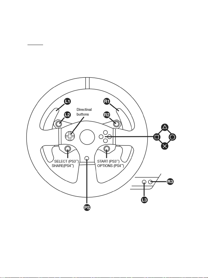
TECHNICAL FEATURES
1 T300 RS base
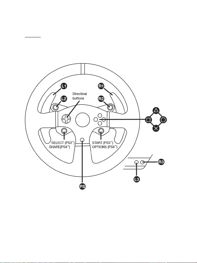
7 SELECT/START buttons on PS3™ and
11 Metal fastening screw
12 Thrustmaster Quick Release
(varies from one country to another)
15 Racing wheel USB cable and connector
17 Pedal set connector
2 T300 GT wheel
3 2 sequential paddle shifters (up & down)
4 Directional buttons
5 Built-in USB sliding switch for PS4™/PS3™
6 MODE button + red/green indicator light
SHARE/OPTIONS on PS4™
8 PS button
9 Large threaded hole (for attachment system
and fastening screw)
10 Attachment system
13 L3/R3 buttons
14 Power supply connector (type A or B)
16 Gearbox connector
(gearbox sold separately)
Page 4
3/24
Internal, with:
Internal, with:
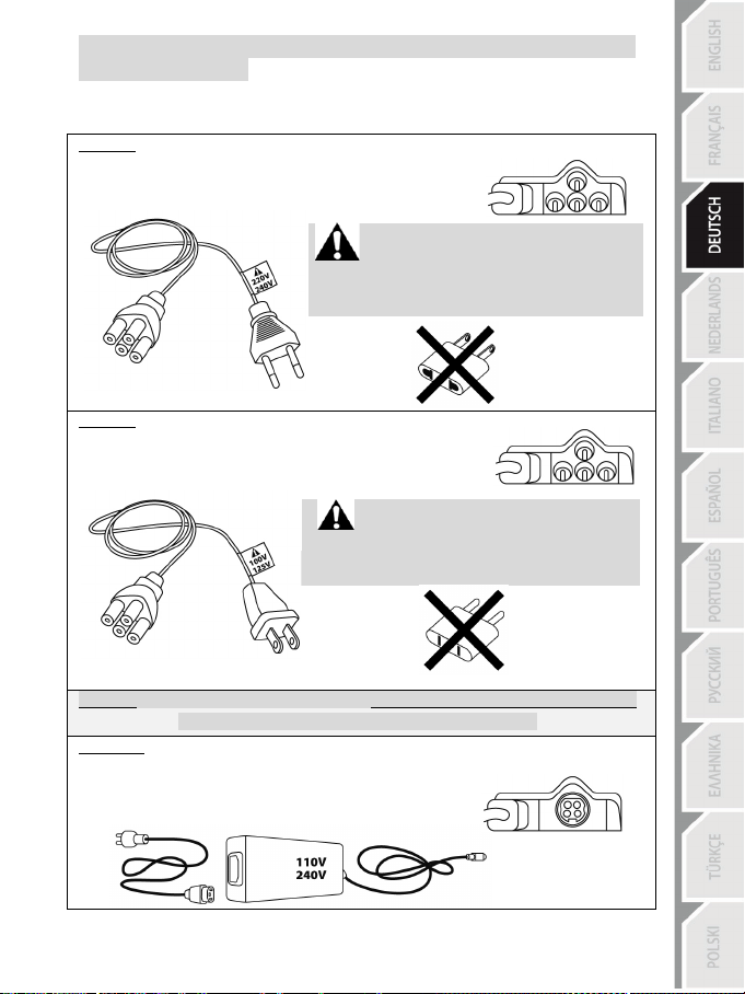
IMPORTANT: if you do not know which voltage is supplied in the area in which you are using
External, with:
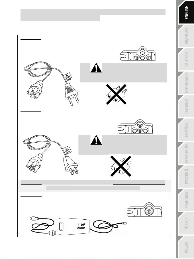
PLUGGING THE RACING WHEEL INTO AN ELECTRICAL OUTLET: PLEASE READ BEFORE PROCEEDING!
Your racing wheel’s power supply varies according to the country where you purchased your device.
The power supply can be:
* a power supply unit located directly inside the racing wheel’s base, with a type A
connector.
* a 220-240 V power supply cable.
= compatible only with 220-240 V electrical power.
Never connect the 220-240 V cable
to a 100-130 V electrical outlet!!!
Never connect this cable to a power adapter!!!
* a power supply unit located directly inside the racing wheel’s base, with a type A
connector.
* a 100-125 V power supply cable.
= compatible only with 100-125 V electrical power.
Never connect the 100-125 V cable
to a 220-240 V electrical outlet!!!
Never connect this cable to a power adapter!!!
* an external power supply unit, with a type B connector.
* a power supply cable.
= compatible with all electrical voltages, from 110-240 V.
your racing wheel, please ask your local electricity supplier.
Page 5

4/24
WARNING
Before using this product, please read this manual carefully and save it for later reference.
Warning – Electrical shock
* Keep the product in a dry location and do not expose it to dust or sunlight.
* Do not twist or pull on the connectors and cables.
* Do not spill any liquid on the product or its connectors.
* Do not short-circuit the product.
* Never dismantle the product; do not throw it onto a fire and do not expose it to high temperatures.
* Do not use a power supply cable other than the one provided with your racing wheel.
* Do not use the power supply cable if the cable or its connectors are damaged, split or broken.
* Make sure that the power supply cable is properly plugged into an electrical outlet, and properly
connected to the connector at the rear of the racing wheel’s base.
* Do not open up the racing wheel: there are no user-serviceable parts inside. Any repairs must be
carried out by the manufacturer, its authorised representative or a qualified technician.
* Only use attachment systems/accessories specified by the manufacturer.
* If the racing wheel is operating abnormally (if it is emitting any abnormal sounds, heat or odours), stop
using it immediately, unplug the power supply cable from the electrical outlet and disconnect the other
cables.
* If you will not be using the racing wheel for an extended period of time, unplug its power supply cable
from the electrical outl et.
* The power outlet shall be installed near the equipment and shall be easily accessible.
Air vents
Make sure not to block any of the air vents on the racing wheel’s base. For optimal ventilation, make sure
to do the following:
* Position the wheel’s base at least 10cm away from any wall surfaces.
* Do not place the base in any tight spaces.
* Do not cover the base.
* Do not let any dust build up on the air vents.
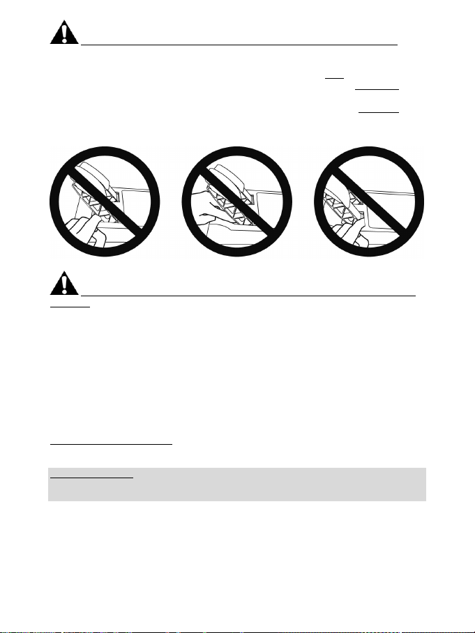
For safety reasons, never use the pedal set with bare feet
THRUSTMASTER® DISCLAIMS ALL RESPONSIBILITY IN THE EVENT OF
INJURY RESULTING FROM USE OF THE PEDAL SET WITHOUT SHOES.
Warning – Injuries due to force feedback and repeated movements
Playing with a force feedback racing wheel may cause muscle or joint pain. To avoid any problems:
* Avoid lengthy gaming periods.
* Take 10 to 15 minute breaks after each hour of play.
* If you feel any fatigue or pain in your hands, wrists, arms, feet or legs, stop playing and rest for a few
hours before you start playing again.
or while wearing only socks on your feet.
Page 6

5/24
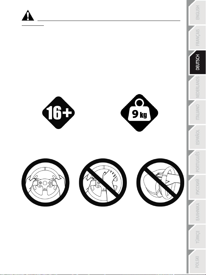
16 years of age or older
yourself or on anyone else!
Warning – Injuries due to force feedback and repeated movements (continued)
* If the symptoms or pain indicated persist when you start playing again, stop playing and consult your
doctor.
* Keep out of children’s reach.
* During gameplay, always leave both hands correctly positioned on the wheel without completely
letting go.
* During gameplay, never place your hands or your fingers under the pedals or anywhere near the
pedal set.
* During calibration and gameplay, never place your hand or your arm through the openings in the
racing wheel.
* Make sure that the racing wheel’s base is properly secured, as per this manual’s instructions.
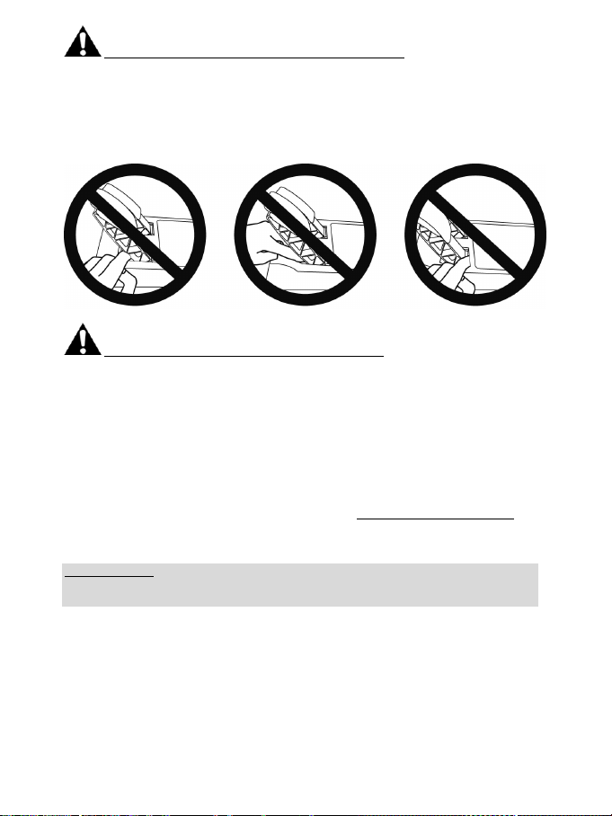
HEAVY PRODUCT
Product to be handled only by users
ALWAYS NEVER NEVER
Be careful not to drop the product on
Page 7

6/24
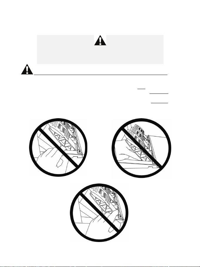
Warning – Pedal set pinch hazard when playing
* Keep the pedal set out of children’s reach.
* During gameplay, never place your fingers on or anywhere near the sides of the pedals.
* During gameplay, never place your fingers on or anywhere near the pedal’s rear base.
* During gameplay, never place your fingers on or anywhere near the pedal’s front base.
NEVER NEVER NEVER
Warning – Pedal set pinch hazard when not playing
* Store the pedal set in a safe place, and keep it out of children’s reach.
UPDATING YOUR RACING WHEEL’S FIRMWARE
The firmware included in your racing wheel’s base can be updated to a more recent version featuring
product enhancements.
To display the firmware version that your racing wheel is currently using and update it if required: on
PC, visit http://support.thrustmaster.com. Click Racing Wheels / T300 RS, then select Firmware
and follow the instructions describing the download and installation procedure.
Important note:
On PC, the USB sliding switch (5) on the racing wheel’s base must always be set to the PS3™
position.
Page 8
7/24
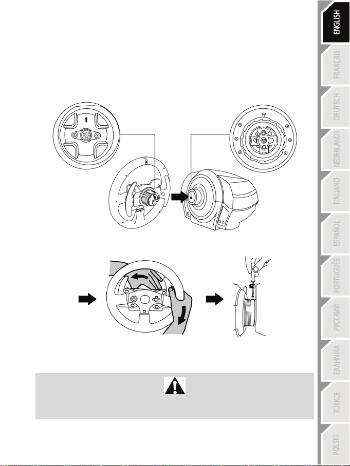
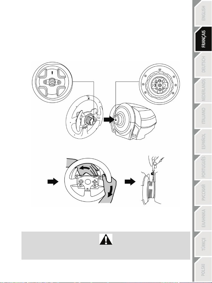
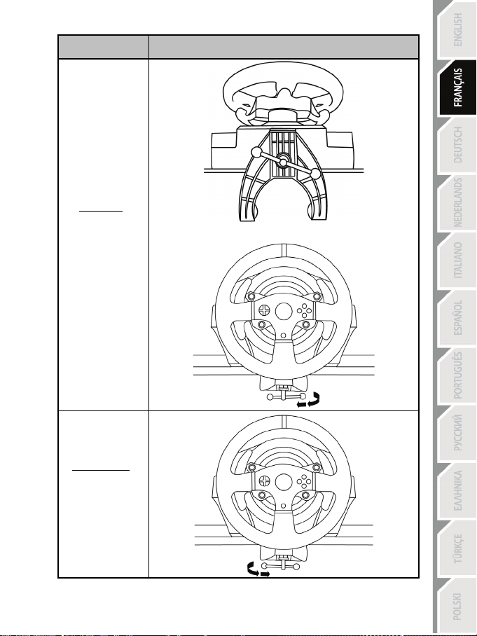
INSTALLING THE WHEEL ON ITS BASE
Align the connector positions using the arrows:
Base (1) connector: Arrow pointing upwards
Racing wheel (2) connector: Arrow pointing upwards
Once the connectors are correctly positioned, simply rotate the Thrustmaster Quick Release (12) device’s
ring anticlockwise, while holding the racing wheel (2) in position.
Then, tighten the ring as much as you can: to do so, hold the ring in position and rotate the racing wheel
clockwise.
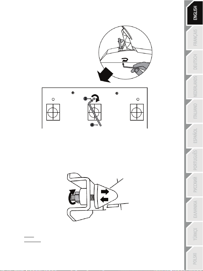
Once you have installed the wheel, rotate it 180° (when facing the wheel, the GT logo should be upside
down) to access the small attachment screw located on the ring of the Thrustmaster Quick Release (12)
device. Use a large Phillips screwdriver to tighten the small attachment screw (do not use excessive
force), turning it clockwise.
When using a Philips screwdriver, ensure NOT to use excessive force
when tightening the small attachment screw!
Stop turning the screw as soon as you feel some resistance.
Page 9

8/24
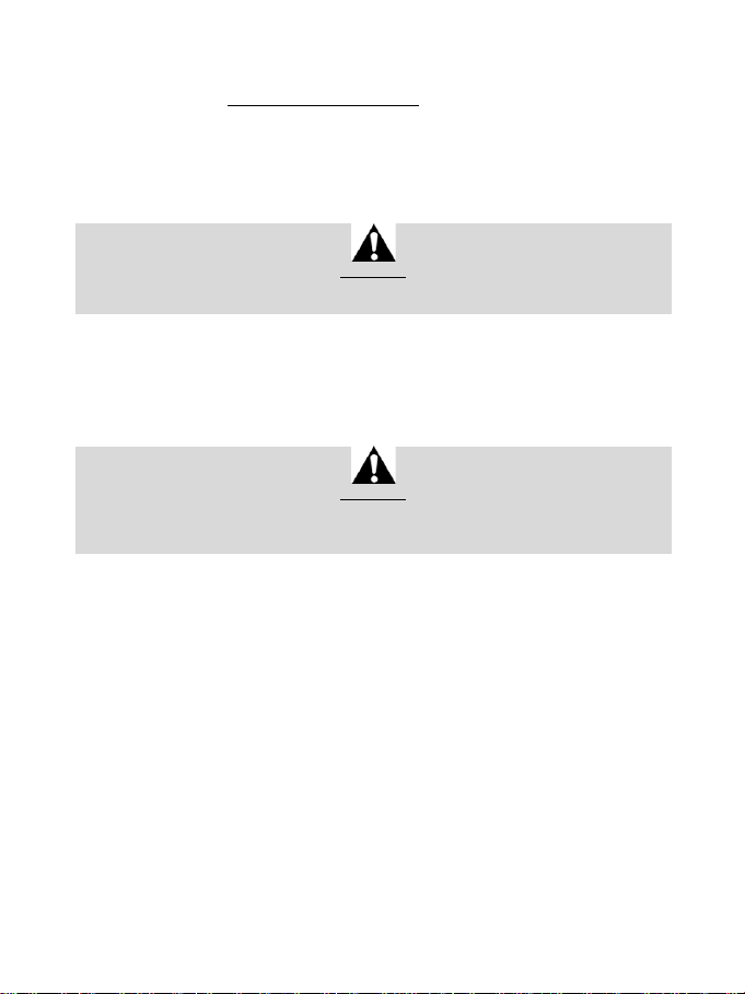
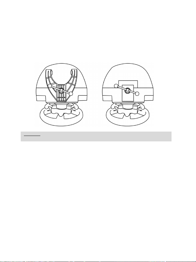
ATTACHING THE RACING WHEEL
WARNING: Never tighten the screw alone, without the attachment system in place!
Attaching the racing wheel to a table or a desktop
1. Place the racing wheel on a table or any other horizontal, flat and stable surface.
2. Insert the fastening screw (11) in the attachment system (10), then tighten the device by turning
the screw anticlockwise, so that it feeds into the large threaded hole (9) located beneath the
racing wheel, until the wheel is perfectly stable.
ALWAYS NEVER
(This could damage the racing wheel.)
Page 10

9/24
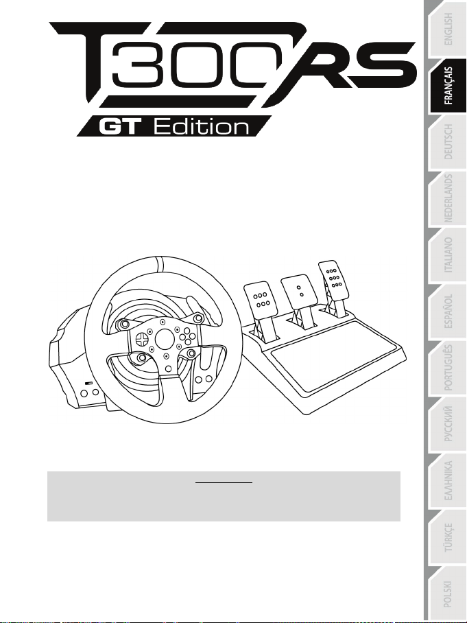
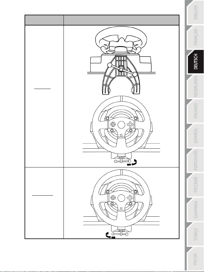
ATTACHMENT /
REMOVAL
DIRECTION
To tighten:
Turn the screw
anticlockwise
To release:
Turn the screw
clockwise
Page 11
10/24
Attaching the racing wheel’s base to a cockpit
1. Place the racing wheel’s base on the cockpit shelf.
2. Drive two M6 screws (not included) through the cockpit shelf, then feed them into the two small
screw threads located on the underside of the racing wheel.
Important: The length of the two M6 screws must not exceed the thickness of the shelf + 12 mm;
longer screws could cause damage to internal components located in the racing wheel’s base.
3. If required, tighten the standard attachment system by inserting the fastening screw in the large
threaded hole.
PLAYSTATION®3 AND PLAYSTATION®4 MAPPING
Page 12

11/24
SETTING UP THE RACING WHEEL FOR PLAYSTATION®3 OR
LAYSTATION®4
P
1. Connect the pedal set to the connector (17) located at the back of the racing wheel's base.
2. Connect the power supply cable to the connector (14) located at the back of the racing wheel's
base.
3. Plug the power supply cable into an electrical outlet with the same voltage specifications.
4. Set the USB sliding switch (5) on the racing wheel’s base to either the PS3™ or PS4™ position,
5. Connect the racing wheel’s USB connector (15) to one of the system’s USB ports.
6. Once your system is powered on, your racing wheel will calibrate itself automatically.
7. On PlayStation
You are now ready to play!
Important notes:
- The USB sliding switch (5) on the racing wheel’s base must always be set to the proper
position (PS3™ or PS4™) before connecting the wheel’s USB cable to the system. To change
the sliding switch’s position, disconnect the USB cable from the system and then change the
position of the switch before reconnecting the USB cable to the system.
- On PlayStation
* The wheel is recognised in most games as a T500RS wheel.
* The wheel is functional in compatible games and in system menus.
* The “PS” function is functional on the wheel.
- On PlayStation
* The wheel is recognised in most games as a T500RS wheel.
* The wheel is functional in compatible games, but not in system menus.
* The “SHARE” and “PS” functions are not functional on the wheel.
- On PlayStation
* Don't forget to press the racing wheel’s PS button (8) in order to be able to use the wheel.
* The wheel is recognised in most games as a T300 RS wheel.
* The wheel is functional in compatible games and in system menus.
* The “SHARE” and “PS” functions are functional on the wheel.
- The list of PlayStation
the required position for the USB sliding switch (5) according to the game being played) is
available at:
For more information about this, please refer to the PLUGGING THE RACING
WHEEL INTO AN ELECTRICAL OUTLET section, on page 3 in this manual.
depending on the system or the game you are using.
wheel’s PS button (8) and sign in to your Sony Entertainment Network account, in order to be able
to use the wheel.
®4 (when the USB sliding switch is set to the PS4™ position): press the racing
®3, the USB sliding switch (5) must always be set to the PS3™ position:
®4, with the USB sliding switch (5) in the PS3™ position:
®4, with the USB sliding switch (5) in the PS4™ position:
®3 and PlayStation®4 games compatible with the T300 RS (along with
http://support.thrustmaster.com
(click Racing Wheels / T300 RS / Games settings).
This list is updated regularly.
Page 13
12/24
SETTING UP THE RACING WHEEL FOR PC*
* PC compatibility not tested nor endorsed by Sony Interactive Entertainment Eur ope.
For more information, visit http://support.thrustmaster.com.
AUTOMATIC RACING WHEEL AND PEDAL SET CALIBRATION
The wheel automatically self-calibrates when you plug the racing wheel into an electrical outlet and
connect the racing wheel’s USB connector to the system.
During this phase, the racing wheel will rotate quickly towards the left and the right, covering a 1080
degree angle, before stopping at the centre.
Never touch the racing wheel during the self-calibration phase!
(This could result in improper calibration and/or personal injuries.)
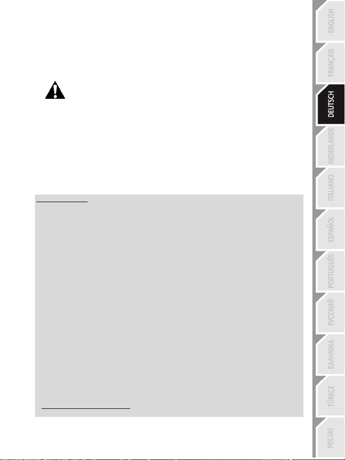
WARNING:
AUTOMATIC CALIBRATION OF THE PEDAL SET
Never connect the pedal set to the racing wheel’s base (or disconnect it from the base) when it is
connected to the system or during gameplay (this could result in improper calibration).
Always connect the pedal set before connecting the racing wheel to the system.
Once the racing wheel’s calibration is complete and the game has been started, the pedals are
automatically calibrated after a few presses.
Never press the pedals during the racing wheel's
self-calibration phase or while a game is loading!
(This could result in improper calibration.)
WARNING:
If your racing wheel and/or pedal set do not function correctly, or if they seem to be improperly
calibrated:
Power off your system and completely disconnect the racing wheel. Then reconnect all cables (including
the power supply cable and the pedal set), and restart your system and your game.
INTERNAL TEMPERATURE SENSOR
The wheel’s cooling system is composed of a heat sink and a fan.
• A thermostat monitors the wheel’s internal temperature.
• When you are using the wheel in a game:
- The cooling fan starts up when the wheel has reached a certain temperature (after a few minutes
of gameplay, depending on the strength of the Force Feedback effects used).
- The power of the Force Feedback effects automatically decreases as soon as the wheel reaches
a much higher temperature level (to protect the motor). The power of these effects automatically
increases as soon as the temperature slightly decreases.
• When you’re done playing: due to the motor’s thermal inertia, the cooling fan continues to operate
until the temperature drops below the fan’s startup level. Your wheel has been designed in this way
in order to facilitate cooling, and to protect the motor (this may take from 5 to 45 minutes, depending
on the temperature reached while using the wheel in a game).
Page 14

13/24
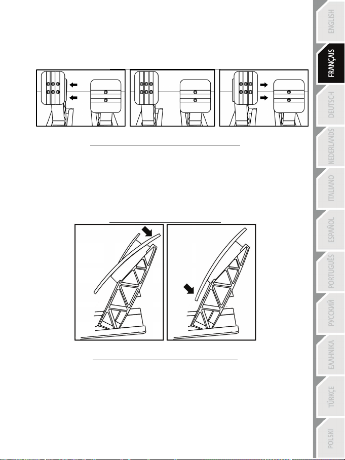
GAS AND CLUTCH PEDALS
Colour of the MODE indicator light (6)
NORMAL
RED
SWAPPED AROUND
GREEN
MODE BUTTON AND INDICATOR LIGHT (6)
MODE button for the pedal set
You can electronically swap the accelerator and clutch pedals.
To do so, simply press the MODE button (6) for 2 seconds.
The racing wheel’s internal memory stores whether the pedals have been swapped around or not.
Other information regarding the MODE button
To learn more about the MODE button and indicator light, please visit
http://support.thrustmaster.com. Click Racing Wheels / T300 RS, and then select Manual or FAQ.
HELP FILES AND FAQS (NOT INCLUDED IN THIS MANUAL)
Please visit http://support.thrustmaster.com. Click Racing Wheels / T300 RS, and then select
Manual or FAQ.
Page 15

14/24
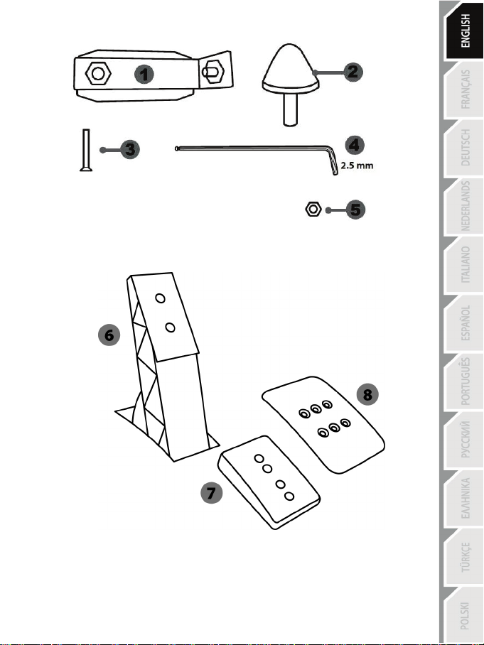
T3PA – GT EDITION PEDAL SET
Page 16
15/24
1 Metal support for conical stop
3 Attachment screw for metal support
4 2.5 mm Allen key (included)
6 Pedal arm
8 Metal pedal head
TECHNICAL FEATURES
(not installed by default)
2 Conical stop
5 Position adjustment nut for conical stop
7 Plastic head support
Page 17

16/24
WARNING
NEVER
NEVER
NEVER
Before using this product, be sure to read these instructions carefully and save them for future reference.
For safety reasons, never use the pedal set with bare feet or while wearing
THRUSTMASTER® DISCLAIMS ALL RESPONSIBILITY IN THE EVENT OF
INJURY RESULTING FROM USE OF THE PEDAL SET WITHOUT SHOES.
Warning – Pedal set pinching hazard during gaming sessions
* Keep the pedal set out of the reach of children.
* During gaming sessions, never place your fingers or thumbs on or near the sides of the pedals.
* During gaming sessions, never place your fingers or thumbs on or near the rear base of the pedals.
* During gaming sessions, never place your fingers or thumbs on or near the front base of the pedals.
only socks on your feet.
Page 18
17/24
AUTOMATIC CALIBRATION OF PEDALS
- Never connect or disconnect the pedal set from the base of the wheel when the wheel is
connected to the PS3™ or PS4™ system, or during gaming sessions, to avoid calibration
problems.
= Always connect the pedal set to the wheel before connecting the wheel to the PS3™ or PS4™
system.
- Once the wheel has self-calibrated and the game has started, the pedals automatically calibrate
themselves after being pressed a few times.
- Never press on the pedals when the wheel is self-calibrating or when your game is starting up, to
avoid calibration problems.
- If the pedals are not functioning correctly or appear to be improperly calibrated, power off your
system, completely disconnect your wheel, then reconnect all of the cables (including the power
supply cable and the pedal set cable), power the system back on and restart your game.
IMPORTANT:
ATTACHING THE PEDAL SET TO A COCKPIT
- Attach the pedal set using the small screw threads located on the underside of the pedal set.
- Screw two M6 screws (not included) into the cockpit’s pedal support plate and into the two small
screw threads located on the underside of the pedal set.
Important: The length of the two M6 screws must not exceed the thickness of the cockpit’s pedal
support plate plus an additional 10 mm, to avoid damaging the pedal set’s internal components.
Page 19

18/24
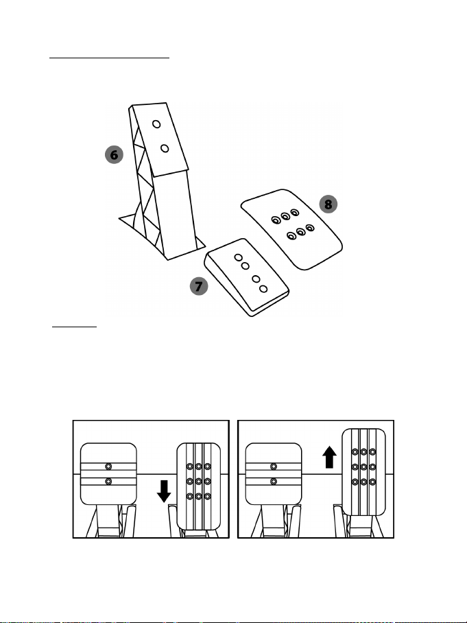
ADJUSTING THE PEDAL SET
Each of the three pedals includes:
- A metal head (8) with multiple perforations (nine for the accelerator – two for the brake – six for the
clutch).
- A plastic head support (7) (placed between the head and the arm) with four perforations.
- A pedal arm (6) with two perforations.
ATTENTION: To avoid any calibration problems, be sure to always disconnect your wheel’s
USB cable from the PS3™ or PS4™ system before making any adjustments to your pedal
set.
Adjusting the HEIGHT of the accelerator pedal
- Using the included 2.5 mm Allen key (4), unscrew the two screws holding the metal head (8) and
its support (7) in place.
- Select your preferred height position, then replace and re-tighten the screws so that the metal
head (8) and its support (7) are held firmly in place.
Low position (default) High position
Page 20
19/24
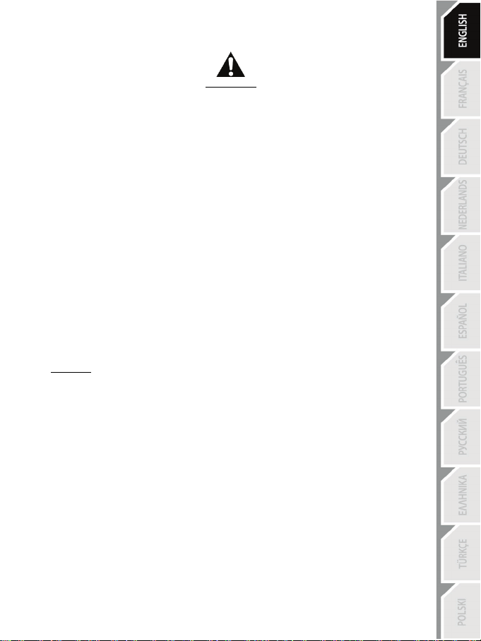
Adjusting the SPACING
- Using the included 2.5 mm Allen key (4), unscrew the two screws holding the metal head (8) and
its support (7) in place.
- Select your preferred position (to the left, centered, or to the right), then replace and re-tighten the
screws so that the metal head (8) and its support (7) are held firmly in place.
Examples illustrating the clutch pedal:
Left position Centered position (default) Right position
Number of possible spacing positions per pedal:
- Three for accelerator pedal
- Three for clutch pedal
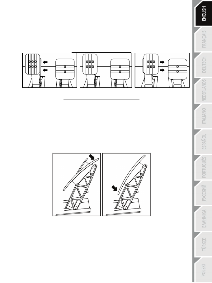
Adjusting the INCLINATION of the pedals
- Using the included 2.5 mm Allen key (4), unscrew the two screws holding the metal head (8) and
its support (7) in place.
- Turn the plastic head support (7) 180°, then replace and re-tighten the screws so that the metal
head (8) and its support (7) are held firmly in place.
Examples illustrating the accelerator pedal:
Less inclined position More inclined position (default)
Number of possible inclination positions per pedal:
- Two for accelerator pedal
- Two for brake pedal
- Two for clutch pedal
Page 21
20/24
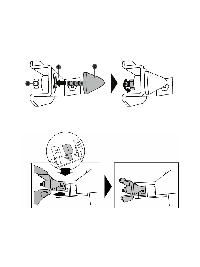
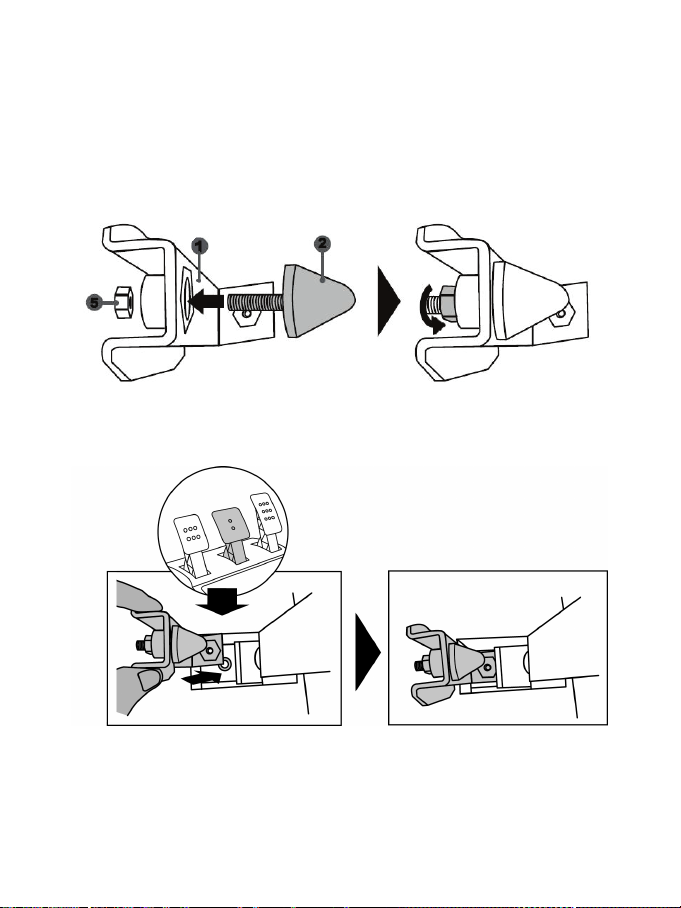
Installing the conical stop (“CONICAL RUBBER BRAKE” mod)
This modification (or “mod”) is not essential, and is not installed by default. This means that the
brake pedal functions perfectly even if the m od is not installed.
This mod lets you experience a different feeling and resistance when braking.
It’s up to you whether or not to install it, depending on your own preferences.
- Screw the conical stop (2) onto its metal support (1).
- Screw the position adjustment nut (5) onto the bottom (onto the conical stop’s screw thread).
- Position the unit at the back of the brake pedal’s arm.
Page 22
21/24
- Using the included 2.5 mm Allen key (4), attach the unit using the attachment screw (3) and the
small central screw thread located on the underside of the pedal set.
The “CONICAL RUBBER BRAKE” mod is now installed!
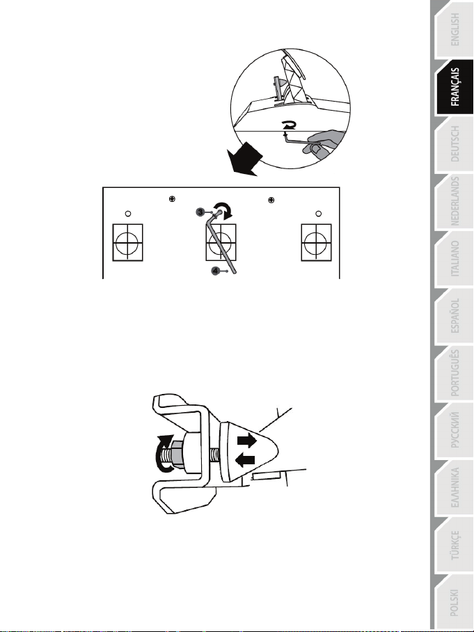
Adjusting the brake pedal’s RANGE of travel and STRENGTH of resistance
By slightly unscrewing the nut (5), you can further strengthen the resistance of the brake pedal by
moving the conical stop (2) closer to the back of the pedal’s arm (if necessary, use a 14 mm wrench
or pliers to re-tighten the nut and maintain the selected position). The closer the conical stop is
positioned to the back of the pedal’s arm, the greater the strength of resistance will be.
Note: When the conical stop is very close to the back of the brake pedal’s arm, you may experience
difficulties in reaching the maximum calibration value. Should that be the case:
* Slowly, press very hard on the brake pedal so as to reach the maximum value (if necessary, stand
very briefly on the pedal – just for a second), then release the pressure; or else
* Move the conical stop a bit farther away from the back of the brake pedal’s arm.
Page 23

22/24
CONSUMER WARRANTY INFORMATION
Worldwide, Guillemot Corporation S.A., whose registered office is located at Place du Granier, B.P.
97143, 35571 Chantepie, France (hereinafter “Guillemot”) warrants to the consumer that this
Thrustmaster product shall be free from defects in materials and workmanship, for a warranty period
which corresponds to the time limit to bring an action for conformity with respect to this product. In
the countries of the European Union, this corresponds to a period of two (2) years from delivery of
the Thrustmaster product. In other countries, the warranty period corresponds to the time limit to
bring an action for conformity with respect to the Thrustmaster product according to applicable laws
of the country in which the consumer was domiciled on the date of purchase of the Thrustmaster
product (if no such action exists in the corresponding country, then the warranty period shall be one
(1) year from the original date of purchase of the Thrustmaster product).
Should the product appear to be defective during the warranty period, immediately contact
Technical Support, who will indicate the procedure to follow. If the defect is confirmed, the product
must be returned to its place of purchase (or any other location indicated by Technical Support).
Within the context of this warranty, the consumer’s defective product shall, at Technical Support’s
option, be either replaced or returned to working order. If, during the warranty period, the
Thrustmaster product is subject to such reconditioning, any period of at least seven (7) days during
which the product is out of use shall be added to the remaining warranty period (this period runs
from the date of the consumer’s request for intervention or from the date on which the product in
question is made available for reconditioning, if the date on which the product is made available for
reconditioning is subsequent to the date of the request for intervention). If permitted under
applicable law, the full liability of Guillemot and its subsidiaries (including for consequential
damages) is limited to the return to working order or the replacement of the Thrustmaster product. If
permitted under applicable law, Guillemot disclaims all warranties of merchantability or fitness for a
particular purpose.
This warranty shall not apply: (1) if the product has been modified, opened, altered, or has suffered
damage as a result of inappropriate or abusive use, negligence, an accident, normal wear, or any
other cause unrelated to a material or manufacturing defect (including, but not limited to, combining
the Thrustmaster product with any unsuitable element, including in particular power supplies,
rechargeable batteries, chargers, or any other elements not supplied by Guillemot for this product);
(2) if the product has been used for any use other than home use, including for professional or
commercial purposes (game rooms, training, competitions, for example); (3) in the event of failure to
comply with the instructions provided by Technical Support; (4) to software, said software being
subject to a specific warranty; (5) to consumables (elements to be replaced over the product’s
lifespan: disposable batteries, audio headset or headphone ear pads, for example); (6) to
accessories (cables, cases, pouches, bags, wrist-straps, for example); (7) if the product was sold at
public auction.
This warranty is nontransferable.
The consumer’s legal rights with respect to laws applicable to the sale of consumer goods in his or
her country are not affected by this warranty.
Page 24

23/24
TECHNICAL SUPPORT
http://support.thrustmaster.com
Additional warranty provisions
During the warranty period, Guillemot shall not provide, in principle, any spare parts, as Technical
Support is the only party authorized to open and/or recondition any Thrustmaster product (with the
exception of any reconditioning procedures which Technical Support may request that the
consumer carry out, by way of written instructions – for example, due to the simplicity and the lack
of confidentiality of the reconditioning process – and by providing the consumer with the required
spare part(s), where applicable).
Given its innovation cycles and in order to protect its know-how and trade secrets, Guillemot shall
not provide, in principle, any reconditioning notification or spare parts for any Thrustmaster product
whose warranty period has expired.
Liability
If permitted under applicable law, Guillemot Corporation S.A. (hereinafter “Guillemot”) and its
subsidiaries disclaim all liability for any damages caused by one or more of the following: (1) the
product has been modified, opened or altered; (2) failure to comply with assembly instructions; (3)
inappropriate or abusive use, negligence, an accident (an impact, for example); (4) normal wear; (5)
the use of the product for any use other than home use, including for professional or commercial
purposes (game rooms, training, competitions, for example). If permitted under applicable law,
Guillemot and its subsidiaries disclaim all liability for any damages unrelated to a material or
manufacturing defect with respect to the product (including, but not limited to, any damages caused
directly or indirectly by any software, or by combining the Thrustmaster product with any unsuitable
element, including in particular power supplies, rechargeable batteries, chargers, or any other
elements not supplied by Guillemot for this product).
Page 25

24/24
COPYRIGHT
*
*
© 2017 Guillemot Corporation S.A. All rights reserved. Thrustmaster® is a registered trademark of
Guillemot Corporation S.A.
Licensed for sale in Europe, Africa, Middle East, Russia, India and Oceania. For use exclusively with
PlayStation
®3 and PlayStation®4.
All other trademarks and brand names are hereby acknowledged and are property of their respective
owners. Illustrations not binding. Contents, designs and specifications are subject to change without
notice and may vary from one country to another. Made in China.
Manufactured and distributed by Guillemot Corporation S.A.
ENVIRONMENTAL PROTECTION RECOMMENDATION
In the European Union: At the end of its working life, this product should not be
disposed of with standard household waste, but rather dropped off at a collection point
for the disposal of Waste Electrical and Electronic Equipment (WEEE) for recycling.
This is confirmed by the symbol found on the product, user manual or packaging.
Depending on their characteristics, the materials may be recycled. Through recycling
and other forms of processing Waste Electrical and Electronic Equipment, you can
make a significant contribution towards helping to protect the environment.
Please contact your local authorities for information on the collection point nearest you.
For all other countries: Please adhere to local recycling laws for electrical and electronic equipment.
Retain this information. Colours and decorations may vary.
Plastic fasteners and adhesives should be removed from the product before it is used.
www.thrustmaster.com
*Applicable to EU and T urkey only
Page 26
1/24
Manuel de l’utilisateur
ATTENTION :
Pour que le volant T300 fonctionne correctement avec les jeux,
il peut être nécessaire d’installer les mises à jour automatiques de ces jeux
(disponibles lorsque votre système est connecté à Internet).
Page 27

2/24
CARACTERISTIQUES TECHNIQUES
1 Base T300 RS
6 Bouton MODE + Voyant lumineux rouge/vert
7 Boutons SELECT/START sur PS3™
11 Vis de serrage métallique
12 Thrustmaster Quick Release
secteur (diffère d’un pays à l’autre)
15 Câble et connecteur USB du volant
17 Connecteur pour le pédalier
2 Roue T300 GT
3 2 leviers séquentiels de changement de
vitesse (up & down)
4 Croix multidirectionnelle
5 Sélecteur USB intégré pour PS4™/PS3™
et SHARE/OPTIONS sur PS4™
8 Bouton PS
9 Gros pas de vis (pour le système de
fixation et la vis de serrage)
10 Système de fixation
13 Boutons L3 / R3
14 Connecteur type A ou B pour l’alimentation
16 Connecteur pour la boîte de vitesses
(boîte de vitesses vendue sépar ément)
Page 28

3/24
Soit interne avec :
Soit interne avec :
IMPORTANT : Si vous ne connaissez pas le voltage de la zone
Soit externe avec :
RELIER LE VOLANT AU SECTEUR = A LIRE IMPERATIVEMENT
En fonction du pays où vous avez acheté votre volant, l’alimentation secteur de votre volant diffère.
Elle est :
* Boitier d’alimentation directement dans la base du volant avec connecteur type A
* Câble d’alimentation secteur 220-240V.
= uniquement compatible avec du courant 220-240V.
Ne jamais brancher le câble 220-240V
sur une prise de courant 100-130V !!!
Ne jamais relier ce câble à un adaptateur secteur !!!
* Boitier d’alimentation directement dans la base du volant avec connecteur type A
* Câble d’alimentation secteur 100-125V.
= uniquement compatible avec du courant 100-125V.
Ne jamais brancher le câble 100-125V
sur une prise de courant 220-240V !!!
Ne jamais relier ce câble à un adaptateur secteur !!!
* Boitier d’alimentation externe à la base du volant avec connecteur type B
* Câble d’alimentation secteur
= compatible avec tout type de courant 110-240V.
dans laquelle vous utilisez le volant, reportez-vous- au fournisseur local d’électricité.
Page 29

4/24
AVERTISSEMENTS
Avant d’utiliser ce produit, lisez attentivement cette documentation et conservez-la pour pouvoir la
consulter ultérieurement.
Avertissement – Choc électrique
* Conservez le produit dans un endroit sec et ne l’exposez ni à la poussière ni au soleil.
* Ne tordez pas et ne tirez pas sur les connecteurs et câbles.
* Ne renversez pas de liquide sur le produit et ses connecteurs.
* Ne mettez pas le produit en court-circuit.
* Ne démontez jamais le produit, ne le jetez pas au feu et ne l’exposez pas à des températures élevées.
* N’utilisez pas de câble d’alimentation autre que celui fourni avec votre volant.
* N’utilisez pas le câble d’alimentation secteur si celui-ci où ses connecteurs sont endommagés, fendus
ou cassés.
* Assurez-vous que le câble d’alimentation secteur est parfaitement inséré dans la prise murale et dans
son connecteur situé à l’arrière de la base du volant.
* N’ouvrez pas l’appareil. L’appareil ne contient pas de pièces réparables par l'utilisateur. Confiez toute
réparation au fabricant, à une agence spécifiée ou un technicien qualifié.
* Utilisez uniquement les systèmes de fixation /accessoires spécifiés par le fabricant.
* Si le volant fonctionne de manière anormale (s’il émet des sons, de la chaleur ou des odeurs
anormales), arrêtez immédiatement de l’utiliser, débranchez le câble d’alimentation de la prise
électrique et déconnectez les autres câbles.
* Lorsque vous n’utilisez pas le volant pendant une période prolongée, débranchez le câble
d’alimentation secteur de la prise électrique.
Grilles d’aération
Veuillez à n’obstruer aucune grille d’aération de la base du volant. Pour assurer une ventilation optimale,
respectez les points ci-après :
* Placez la base à 10 cm au moins d’une surface murale.
* Ne placez pas la base dans un endroit exigu.
* Ne couvrez pas la base.
* Ne laissez pas la poussière s’accumuler sur les grilles d’aération.
Pour des raisons de sécurité, ne jouez pas pieds nus ou en chaussettes
THRUSTMASTER® DECLINE TOUTE RESPONSABILITE EN CAS DE
BLESSURE SUITE A UNE UTILISATION DU PEDALIER SANS CHAUSSURES.
Avertissement – Blessures dues au retour de force et aux mouvements répétitifs
Jouer avec un volant à retour de force peut causer des douleurs aux muscles et aux articulations. Afin
d’éviter tout problème :
* Evitez les périodes trop longues de jeu.
* Faites une pause de 10 à 15 minutes après chaque heure de jeu.
* Si vous éprouvez fatigue ou douleur au niveau des mains, des poignets, des bras, des pieds ou des
jambes, cessez de jouer et reposez-vous pendant quelques heures avant de recommencer à jouer.
lorsque vous utilisez le pédalier.
Page 30

5/24
personnes âgées de 16 ans ou plus
une autre personne
Avertissement – Blessures dues au retour de force et aux mouvements répétitifs (suite)
* Si les symptômes ou les douleurs indiqués ci-dessus persistent lorsque vous reprenez le jeu, arrêtez
de jouer et consultez votre médecin.
* Laissez hors de portée des enfants.
* Lors des phases de jeu, laissez toujours vos deux mains correctement positionnées sur le volant
sans jamais le lâcher complètement.
* Lors des phases de jeu, ne placez jamais vos mains ou vos doigts sous les pédales ou à proximité
du pédalier.
* Lors des phases de calibration et de jeu, ne jamais introduire une main ou un bras à l’intérieur de la
roue du volant.
* Vérifiez que la base du volant est correctement fixée, conformément aux instructions du manuel .
PRODUIT LOURD
Produit à manipuler uniquement par des
TOUJOURS JAMAIS JAMAIS
Ne pas laisser tomber le produit sur vous ou
Page 31
6/24
Avertissement – Risque de pincement au niveau du pédalier lors des phases de jeu
* Laissez le pédalier hors de portée des enfants.
* Lors des phases de jeu, ne placez jamais vos doigts sur ou à proximité des côtés des pédales.
* Lors des phases de jeu, ne placez jamais vos doigts sur ou à proximité de la base arrière des
pédales.
* Lors des phases de jeu, ne placez jamais vos doigts sur ou à proximité de la base avant des
pédales.
JAMAIS JAMAIS JAMAIS
Avertissement – Risque de pincement au niveau du pédalier lorsque vous n’utilisez pas
le pédalier
* Placez le pédalier dans un endroit sûr et hors de portée des enfants.
METTRE A JOUR LE FIRMWARE DU VOLANT
Le firmware inclus dans la base du volant peut être mis à jour (ce qui signifie qu’il peut être mis à jour
par des versions plus récentes comportant des améliorations produits).
Pour afficher la version de firmware de votre volant et le mettre à jour si nécessaire : sur PC, allez sur
http://support.thrustmaster.com, cliquez sur Volants / T300 RS puis Firmware et suivez les
instructions et la procédure de téléchargement et d’installation.
Remarque importante :
Pour fonctionner sur PC, le sélecteur USB (5) de la base du volant doit toujours être en position
PS3™.
Page 32
7/24
INSTALLATION DE LA ROUE SUR SA BASE
Alignez la position des connecteurs en vous aidant des flèches :
Connecteur de la base (1): Flèche vers le haut
Connecteur de la roue (2): Flèche vers le haut
Une fois les connecteurs mis en place, il vous suffit de tourner la bague du Thrustmaster Quick Release
(12) dans le sens inverse des aiguilles d’une montre tout en maintenant la roue (2) fixe.
Puis serrez fortement (et au maximum) la bague en la maintenant fixe et en tournant le volant dans le
sens des aiguilles d’une montre.
Lorsque la roue est installée, tournez-la de 180° (vu de face, le Logo GT doit être à l’envers) afin
d’accéder à la petite vis de fixation située sur la bague du Thrustmaster Quick Release (12). A l’aide d’un
gros tournevis cruciforme, vissez sans forcer la petite vis de fixation dans le sens des aiguilles d’une
montre.
Lorsque vous revissez la petite vis de fixation à l’aide d’un tournevis cruciforme,
NE FORCEZ PAS.
Arrêtez de visser dès que vous sentez une résistance.
Page 33

8/24
FIXATION DU VOLANT
ATTENTION : Ne jamais visser la vis de serrage seule sans le système de fixation !
Fixer le volant sur une table ou un bureau
1. Placez le volant sur une table ou autre surface plane.
2. Placez la vis de serrage (11) dans le système de fixation (10), puis vissez l’ensemble (dans le sens
inverse des aiguilles d’une montre) dans le gros pas de vis (9) situé sous le volant, jusqu’à ce que
ce dernier soit parfaitement stable.
TOUJOURS JAMAIS
(au risque de détériorer le volant).
Page 34
9/24
MONTAGE /
DEMONTAGE
Pour serrer :
Vissez
dans le sens inverse
des aiguilles d’une
montre
SENS
Pour desserrer :
Dévissez
dans le sens
des aiguilles d’une
montre
Page 35
10/24
Fixer la base du volant sur un cockpit
1. Placez la base du volant sur la tablette du cockpit
2. Vissez 2 vis M6 (non fournies) dans la tablette du cockpit et dans les 2 petits pas de vis situés
sous le volant.
Important : La longueur de ces 2 vis M6 ne doit pas dépasser l’épaisseur de votre support
+12 mm pour ne pas endommager les composants internes à la base.
3. Si nécessaire, vissez en plus le système de fixation classique (dans le gros pas de vis).
MAPPING PLAYSTATION®3 ET PLAYSTATION®4
Page 36
11/24
INSTALLATION SUR PLAYSTATION®3 OU PLAYSTATION®4
1. Reliez le pédalier à son connecteur (17) situé à l’arrière de la base du volant.
2. Reliez le câble d’alimentation à son connecteur (14) situé à l’arrière de la base du volant.
3. Reliez le câble d’alimentation sur une prise de courant ayant le même voltage.
4. Positionnez le sélecteur USB (5) de la base du volant en position PS3™ ou PS4™ en fonction du
5. Branchez le connecteur USB (15) du volant sur l’un des ports USB du système.
6. Une fois votre système allumé, votre volant s’autocalibre de manière automatique.
7. Sur PlayStation
Vous êtes maintenant prêt à jouer !
Remarques importantes :
- Le sélecteur USB (5) de la base du volant du toujours être positionné dans la bonne position
(PS3™ ou PS4™) avant de brancher l’USB du volant au système.
Pour changer de position, débranchez le câble USB, puis changez la position du sélecteur
avant de rebrancher le câble USB au système.
- Sur PlayStation®3, le sélecteur USB (5) doit toujours être en position PS3™ :
* Le volant est reconnu dans la plupart des jeux comme un volant T500RS.
* Le volant est fonctionnel dans les jeux compatibles et dans les menus du système.
* La fonction PS est fonctionnelle sur le volant.
- Sur PlayStation®4, avec le sélecteur USB (5) en position PS3™ :
* Le volant est reconnu dans la plupart des jeux comme un volant T500RS.
* Le volant est fonctionnel dans les jeux compatibles mais pas dans les menus du système.
* Les fonctions SHARE et PS ne sont pas fonctionnelles sur le volant.
- Sur PlayStation®4, avec le sélecteur USB (5) en position PS4™ :
* N’oubliez pas d’appuyer sur bouton PS (8) du volant pour que celui-ci soit fonctionnel.
* Le volant est reconnu dans la plupart des jeux comme un volant T300 RS.
* Le volant est fonctionnel dans les jeux compatibles et dans les menus du système.
* Les fonctions SHARE et PS sont fonctionnelles sur le volant.
- La liste des jeux PlayStation®3 et PlayStation®4 compatibles avec le T300 RS (ainsi que la
position nécessaire du sélecteur USB en fonction du jeu utilisé) est disponible ici :
Pour plus d’informations sur ce point, reportez-vous au chapitre RELIER LE
VOLANT AU SECTEUR (p.3 de ce manuel).
système ou du jeu utilisé.
du volant, puis connectez-vous à votre compte Sony Entertainment Network pour que votre volant
soit fonctionnel.
http://support.thrustmaster.com (dans la rubrique Volants / T300 RS / Paramètres de jeux).
®4 (lorsque le sélecteur USB est en position PS4™), appuyez sur le bouton PS (8)
Cette liste est régulièrement mise à jour.
Page 37
12/24
INSTALLATION SUR PC*
*Compatibilité PC non testée ni endossée par S ony Interactive Entertainment Europe
Pour plus d’informations, allez sur http://support.thrustmaster.com.
CALIBRAGE AUTOMATIQUE DU VOLANT ET DES PEDALES
La roue du volant s’autocalibre de manière automatique une fois le volant relié au secteur et le
connecteur USB connecté.
Cette opération entraîne des mouvements rapides du volant de gauche à droite sur 1080° avant de
s’immobiliser au centre.
Lors des phases d’autocalibration de la roue du volant, ne jamais toucher au volant
(au risque de fausser la calibration ou de se blesser).
ATTENTION :
CALIBRAGE AUTOMATIQUE DES PEDALES
Ne jamais débrancher ou brancher le pédalier de la base du volant lorsque celui-ci est connecté au
système ni en cours de jeu (pour ne pas fausser la calibration)
= le pédalier doit toujours être branché avant de relier le volant au système.
Une fois le volant autocalibré et le jeu lancé, les pédales se calibrent automatiquement après quelques
pressions.
Lors des phases d’autocalibration de la roue du volant et lorsque votre jeu se lance,
ne jamais appuyer sur les pédales (au risque de fausser la calibration)
ATTENTION :
Si votre volant et vos pédales ne fonctionnent pas correctement ou semblent mal calibrés :
Eteignez votre système, déconnectez entièrement votre volant, reconnectez tous les câbles (avec le
câble d’alimentation secteur et le pédalier), redémarrez et relancez votre jeu.
CAPTEUR DE TEMPERATURE INTERNE
Le système de refroidissement du volant est composé d’un radiateur et d’un ventilateur.
• Un thermostat calcule la température interne du volant.
• En phase de jeu :
- Le ventilateur de refroidissement se met en marche dès que le volant atteint un certain niveau
de température (= après quelques minutes de jeu en fonction de la puissance des effets de
retour de force utilisés).
- La puissance des effets de retour de force diminue automatiquement dès que le volant atteint un
niveau de température beaucoup plus élevé (afin de protéger le moteur). La puissance de ces
effets remonte automatiquement dès que la température redescend légèrement.
• Après la phase de jeu, en raison de l’inertie thermique du moteur, le ventilateur de
refroidissement reste en marche jusqu’à ce que la température redescende au niveau de mise
en marche, le tout afin de faciliter le refroidissement et de protéger le moteur (= cela peut
prendre de 5 à 45 mn en fonction du niveau de température atteint pendant la phase de jeu).
Page 38
13/24
PEDALE D’ACCELERATEUR ET D’EMBRAYAGE
Couleur du voyant lumineux MODE (6)
NORMALE
ROUGE
INVERSEE
VERT
BOUTON MODE ET SON VOYANT LUMINEUX (6)
Bouton MODE pour le pédalier
Vous pouvez inverser électroniquement la pédale d’accélérateur et d’embrayage.
Pour ce faire, appuyez simplement sur le bouton MODE (6) pendant 2 secondes.
L’inversion ou non des pédales est alors instantanément enregistrée dans la mémoire interne du volant.
Autres astuces pour le bouton MODE
Pour profiter d’autres astuces concernant le bouton MODE et son voyant lumineux, allez sur
http://support.thrustmaster.com. Cliquez sur Volants / T300 RS puis Manuel utilisateur ou FAQ.
AIDES & FAQ DIVERSES (non notifiées dans ce manuel)
Allez sur http://support.thrustmaster.com. Dans la section Mise à jour et téléchargement,
cliquez sur Volants / T300 RS puis Manuel utilisateur ou FAQ.
Page 39

14/24
PEDALIER T3PA – GT EDITION
Page 40

15/24
1 Support métallique pour la butée conique
3 Vis de fixation du support métallique
4 Clé Allen 2,5 mm fournie
6 Bras de pédale
8 Tête métallique de pédale
CARACTÉRISTIQUES TECHNIQUES
(non installée par défaut)
2 Butée conique
5 Ecrou de réglage de position de la butée
conique
7 Support de tête plastique
Page 41
16/24
AVERTISSEMENT
JAMAIS
JAMAIS
JAMAIS
Avant d’utiliser ce produit, lisez attentivement cette documentation et conservez-la pour pouvoir la
consulter ultérieurement.
Pour des raisons de sécurité, ne jouez pas pieds nus ou en chaussettes
THRUSTMASTER® DECLINE TOUTE RESPONSABILITE EN CAS DE
BLESSURE SUITE A UNE UTILISATION DU PEDALIER SANS CHAUSSURES.
Avertissement – Risque de pincement au niveau du pédalier lors des phases de jeu
* Laissez le pédalier hors de portée des enfants.
* Lors des phases de jeu, ne placez jamais vos doigts sur ou à proximité des côtés des pédales.
* Lors des phases de jeu, ne placez jamais vos doigts sur ou à proximité de la base arrière des
pédales.
* Lors des phases de jeu, ne placez jamais vos doigts sur ou à proximité de la base avant des
pédales.
lorsque vous utilisez le pédalier.
Page 42
17/24
CALIBRAGE AUTOMATIQUE DES PEDALES
- Ne branchez ou débranchez jamais le pédalier de la base du volant lorsque celui-ci est connecté
au système PS3™ ou PS4™, ou en cours de jeu, pour ne pas fausser la calibration.
= Branchez toujours le pédalier avant de relier le volant au système PS3™ ou PS4™.
- Une fois le volant autocalibré et le jeu lancé, les pédales se calibrent automatiquement après
quelques pressions.
- Lors des phases d’autocalibration de la roue du volant et lorsque votre jeu se lance, n’appuyez
jamais sur les pédales, au risque de fausser la calibration.
- Si vos pédales ne fonctionnent pas correctement ou semblent mal calibrées, éteignez votre
système, déconnectez entièrement votre volant, reconnectez tous les câbles (y compris le câble
d’alimentation secteur et le câble du pédalier), redémarrez le système et relancez votre jeu.
IMPORTANT :
FIXATION DU PEDALIER SUR UN COCKPIT
- Fixez le pédalier via les petits pas de vis situés sous ce dernier.
- Vissez 2 vis M6 (non fournies) dans la tablette du cockpit et dans les 2 petits pas de vis situés
sous le pédalier.
Important : La longueur de ces 2 vis M6 ne doit pas dépasser l’épaisseur de votre support +10 mm
pour ne pas endommager les composants internes du pédalier.
Page 43
18/24
REGLAGES DU PEDALIER
Chacune des 3 pédales comprend :
- Une tête métallique (8) avec plusieurs perforations (9 pour l’accélérateur – 2 pour le frein – 6 pour
l’embrayage).
- Un support de tête plastique (7) (placé entre la tête et le bras) avec 4 perforations.
- Un bras de pédale (6) avec 2 perforations.
ATTENTION : Pour éviter tout problème de calibration, débranchez toujours le câble USB de
votre volant avant d’effectuer des réglages sur votre pédalier.
Ajuster la HAUTEUR de la pédale d’accélérateur
- A l’aide de la clé Allen 2,5 mm fournie (4), dévissez les 2 vis maintenant la tête métallique (8) et
son support (7).
- Choisissez ensuite votre position en hauteur, puis revissez le tout.
Position basse (par défaut) Position haute
Page 44
19/24
Ajuster l’ECARTEMEMENT
- A l’aide de la clé Allen 2,5 mm fournie (4), dévissez les 2 vis maintenant la tête métallique (8) et
son support (7).
- Choisissez ensuite votre position (à gauche, au centre ou à droite), puis revissez le tout.
Exemples ici avec la pédale d’embrayage :
Position à gauche Position au centre (par défaut) Position à droite
Nombre de positions en écartement possibles par pédale :
- 3 pour la pédale d’accélérateur
- 3 pour la pédale d’embrayage
Ajuster l’INCLINAISON des pédales
- A l’aide de la clé Allen 2,5 mm fournie (4), dévissez les 2 vis maintenant la tête métallique (8) et
son support (7).
- Retournez ensuite le support de tête plastique (7) de 180°, puis revissez le tout.
Exemples ici avec la pédale d’accélérateur:
Position moins inclinée Position plus inclinée (par défaut)
Nombre de positions d’inclinaison possibles par pédale :
- 2 pour la pédale d’accélérateur
- 2 pour la pédale de frein
- 2 pour la pédale d’embrayage
Page 45
20/24
Installer la butée conique (MOD « CONICAL RUBBER BRAKE »)
Ce MOD n’est pas obligatoire et n’est pas installé par défaut. Cela signifie que la pédale de frein
fonctionne parfaitement même si le MOD n’est pas installé.
Ce MOD permet d’apporter un feeling et une résistance différents lors des freinages.
Il appartiendra à chacun de l’installer ou non en fonction de ses préférences.
- Vissez la butée conique (2) sur son support métallique (1).
- Vissez l’écrou de réglage de position (5) à l’arrière (sur le pas de vis de la butée conique).
- Positionnez l’ensemble à l’arrière du bras de la pédale de frein.
Page 46
21/24
- A l’aide de la clé Allen 2,5 mm fournie (4), fixez l’ensemble en utilisant la vis de fixation (3) et le
petit pas de vis central situé sous le pédalier.
Le MOD « CONICAL RUBBER BRAKE » est désormais installé !
Ajuster la COURSE de débattement et la FORCE de résistance de la pédale de
frein
En dévissant légèrement l’écrou (5), vous pouvez également durcir davantage la résistance de la
pédale de frein en rapprochant la butée conique (2) de l’arrière du bras de la pédale (utilisez si
nécessaire une clé de 14 ou une pince pour resserrer l’écrou et maintenir la position souhaitée).
Plus la butée conique sera proche de l’arrière du bras de la pédale, plus la résistance sera élevée.
Remarque : Lorsque la butée conique est très proche de l’arrière du bras de la pédale de frein,
vous pouvez avoir des difficultés à atteindre la valeur maximale de calibration. Dans ce cas :
* Appuyez –lentement– très fortement sur la pédale de frein pour atteindre la valeur maximale (si
nécessaire, mettez-vous debout un court instant sur la pédale), puis relâchez la pression.
* Ou éloignez légèrement la butée conique de l’arrière du bras.
Page 47

22/24
INFORMATIONS RELATIVES A LA GARANTIE AUX CONSOMMATEURS
Dans le monde entier, Guillemot Corporation S.A., ayant son siège social Place du Granier, B.P. 97143, 35571
Chantepie, France (ci-après « Guillemot ») garantit au consommateur que le présent produit Thrustmaster est exempt
de défaut matériel et de vice de fabrication, et ce, pour une période de garantie qui correspond au délai pour intenter
une action en conformité de ce produit. Dans les pays de l’Union Européenne, ce délai est de deux (2) ans à compter de
la délivrance du produit Thrustmaster. Dans les autres pays, la durée de la période de garantie correspond au délai pour
intenter une action en conformité du produit Thrustmaster selon la législation en vigueur dans le pays où le
consommateur avait son domicile lors de l’achat du produit Thrustmaster (si une telle action en conformité n’existe pas
dans ce pays alors la période de garantie est de un (1) an à compter de la date d’achat d’origine du produit
Thrustmaster).
Si, au cours de la période de garantie, le produit semble défectueux, contactez immédiatement le Support Technique
qui vous indiquera la procédure à suivre. Si le défaut est confirmé, le produit devra être retourné à son lieu d’achat (ou
tout autre lieu indiqué par le Support Technique).
Dans le cadre de la garantie, le consommateur bénéficiera, au choix du Support Technique, d'un remplacement ou
d'une remise en état de marche du produit défectueux. Si, pendant la période de garantie, le produit Thrustmaster fait
l'objet d'une telle remise en état, toute période d'immobilisation d'au moins sept jours vient s'ajouter à la durée de la
garantie qui restait à courir (cette période court à compter de la demande d'intervention du consommateur ou de la mise
à disposition pour remise en état du produit en cause, si cette mise à disposition est postérieure à la demande
d'intervention). Lorsque la loi applicable l’autorise, toute responsabilité de Guillemot et ses filiales (y compris pour les
dommages indirects) se limite à la remise en état de marche ou au remplacement du produit Thrustmaster. Lorsque la
loi applicable l’autorise, Guillemot exclut toutes garanties de qualité marchande ou d’adaptation à un usage particulier.
Cette garantie ne s’appliquera pas : (1) si le produit a été modifié, ouvert, altéré, ou a subi des dommages résultant d’une
utilisation inappropriée ou abusive, d’une négligence, d’un accident, de l’usure normale, ou de toute autre cause non liée à un
défaut matériel ou à un vice de fabrication (y compris, mais non limitativement, une combinaison du produit Thrustmaster
avec tout élément inadapté, notamment alimentations électriques, batteries, chargeurs, ou tous autres éléments non-fournis
par Guillemot pour ce produit) ; (2) si le produit a été utilisé en dehors du cadre privé, à des fins professionnelles ou
commerciales (salles de jeu, formations, compétitions, par exemple). (3) en cas de non respect des instructions du Support
Technique ; (4) aux logiciels, lesdits logiciels faisant l’objet d’une garantie spécifique ; (5) aux consommables (éléments à
remplacer pendant la durée de vie du produit : piles, coussinets de casque audio, par exemple) ; (6) aux accessoires (câbles,
étuis, housses, sacs, dragonnes, par exemple) ; (7) si le produit a été vendu aux enchères publiques.
Cette garantie n’est pas transférable.
Les droits légaux du consommateur au titre de la législation applicable dans son pays à la vente de biens de
consommation ne sont pas affectés par la présente garantie.
Par exemple, en France, indépendamment de la présente garantie, le vendeur reste tenu de la garantie légale de
conformité mentionnée aux articles L. 217-4 à L.217-12 du code de la consommation et de celle relative aux défauts
(vices cachés) de la chose vendue, dans les conditions prévues aux articles 1641 à 1648 et 2232 du code civil. La loi
applicable (c'est-à-dire la loi française) impose de reproduire les extraits de la loi française suivants:
Article L. 217-4 du code de la consommation:
Le vendeur livre un bien conforme au contrat et répond des défauts de conformité existant lors de la délivrance.
Il répond également des défauts de conformité résultant de l'emballage, des instructions de montage ou de l'installation
lorsque celle-ci a été mise à sa charge par le contrat ou a été réalisée sous sa responsabilité.
Article L. 217-5 du code de la consommation:
Le bien est conforme au contrat :
1° S'il est propre à l'usage habituellement attendu d'un bien semblable et, le cas échéant :
- s'il correspond à la description donnée par le vendeur et possède les qualités que celui-ci a présentées à l'acheteur
sous forme d'échantillon ou de modèle ;
- s'il présente les qualités qu'un acheteur peut légitimement attendre eu égard aux déclarations publiques faites par le
vendeur, par le producteur ou par son représentant, notamment dans la publicité ou l'étiquetage ;
2° Ou s'il présente les caractéristiques définies d'un commun accord par les parties ou est propre à tout usage spécial
recherché par l'acheteur, porté à la connaissance du vendeur et que ce dernier a accepté.
Article L. 217-12 du code de la consommation:
L'action résultant du défaut de conformité se prescrit par deux ans à compter de la délivrance du bien.
Article L. 217-16 du code de la consommation:
Lorsque l'acheteur demande au vendeur, pendant le cours de la garantie commerciale qui lui a été consentie lors de
l'acquisition ou de la réparation d'un bien meuble, une remise en état couverte par la garantie, toute période
d'immobilisation d'au moins sept jours vient s'ajouter à la durée de la garantie qui restait à courir.
Page 48
23/24
SUPPORT TECHNIQUE
Cette période court à compter de la demande d'intervention de l'acheteur ou de la mise à disposition pour réparation du
bien en cause, si cette mise à disposition est postérieure à la demande d'intervention.
Article L. 1641 du code civil:
Le vendeur est tenu de la garantie à raison des défauts cachés de la chose vendue qui la rendent impropre à l'usage
auquel on la destine, ou qui diminuent tellement cet usage que l'acheteur ne l'aurait pas acquise, ou n'en aurait donné
qu'un moindre prix, s'il les avait connus.
Article L. 1648 alinéa 1er du code civil:
L'action résultant des vices rédhibitoires doit être intentée par l'acquéreur dans un délai de deux ans à compter de la
découverte du vice.
Stipulations additionnelles à la garantie
Pendant la période de garantie, Guillemot ne fournira, en principe, pas de pièce détachée car le Support Technique est
seul habilité tant à ouvrir qu'à remettre en état tout produit Thrustmaster (à l'exception des remises en état que le
Support Technique demanderait, par instructions écrites, au consommateur d'effectuer -par exemple en raison de la
simplicité et de l'absence de confidentialité du processus de remise en état-, en lui fournissant, le cas échéant, la ou les
pièces détachées nécessaires).
Compte tenu de ses cycles d'innovation et pour préserver ses savoir-faire et secrets, Guillemot ne fournira, en principe,
ni notice de remise en état, ni pièce détachée pour tout produit Thrustmaster dont la période de garantie est expirée.
Aux États-Unis d’Amérique et au Canada, la présente garan tie est limitée au mécanisme interne et au boîtier externe du produit. En
aucun cas, Guillemot ou ses sociétés affiliées ne sauraient être tenues responsables envers qui que ce soit de tous dommages
indirects ou dommages accessoires résultant du non respect des garanties expresses ou implicites. Certains États/Provinces
n’autorisent pas la limitation sur la durée d’une garantie implicite, ou l’exclusion ou la limitation de responsabilité pour les dommages
indirects ou accessoires, de sorte que les limitations ou exclusions ci-dessus peuvent ne pas vous être applicables. Cette garantie
vous confère des droits spécifiques ; vous pouvez également bénéficier d’autres droits qui peuvent différer d’un État/Province à
l’autre.
Responsabilité
Lorsque la loi applicable l’autorise, Guillemot Corporation S.A. (ci-après « Guillemot ») et ses filiales excluent toute
responsabilité pour tous dommages causés par un ou plusieurs des faits suivants: (1) le produit a été modifié, ouvert, altéré,
(2) l’irrespect des instructions de montage, (3) l’utilisation inappropriée ou abusive, la négligence, l’accident (un choc, par
exemple), (4) l’usure normale du produit, (5) l’utilisation du produit en dehors du cadre privé, à des fins professionnelles ou
commerciales (salles de jeu, formations, compétitions, par exemple). Lorsque la loi applicable l’autorise, Guillemot et ses
filiales excluent toute responsabilité pour tout dommage dont la cause n’est pas liée à un défaut matériel ou à un vice de
fabrication du produit (y compris, mais non limitativement, tout dommage causé directement ou indirectement par tout logiciel,
ou par une combinaison du produit Thrustmaster avec tout élément inadapté, notamment alimentations électriques, batteries,
chargeurs, ou tous autres éléments non-fournis par Guillemot pour ce produit).
http://support.thrustmaster.com
Page 49
24/24
COPYRIGHT
*
*
© 2017 Guillemot Corporation S.A. Tous droits réservés. Thrustmaster® est une marque déposée de
Guillemot Corporation S.A.
Licence accordée pour la vente en Europe, Afrique, Moyen-Orient, Inde, Russie et Océanie. A utiliser
exclusivement avec PlayStation
®3 et PlayStation®4.
Toutes les autres marques sont la propriété de leurs propriétaires respectifs. Illustrations non
contractuelles. Le contenu, la conception et les spécifications sont susceptibles de changer sans
préavis et de varier selon les pays. Fabriqué en Chine.
Produit et distribué par Guillemot Corporation S.A.
RECOMMANDATION RELATIVE A LA PROTECTION DE L’ENVIRONNEMENT
Dans l’Union Européenne : En fin de vie, ce produit ne doit pas être éliminé avec
les déchets ménagers normaux mais déposé à un point de collecte des déchets
d'équipements électriques et électroniques en vue de son recyclage.
Ceci est confirmé par le symbole figurant sur le produit, le manuel utilisateur ou
l’emballage.
En fonction de leurs caractéristiques, les matériaux peuvent être recyclés. Par le
recyclage et par les autres formes de valorisation des déchets d'équipements
électriques et électroniques, vous contribuez de manière significative à la
protection de l’environnement. Veuillez consulter les autorités locales qui vous indiqueront le point de
collecte concerné.
Dans les autres pays : Veuillez vous reporter aux législations locales relatives au recyclage des
équipements électriques et électroniques.
Informations à conserver. Les couleurs et décorations peuvent varier.
Il est recommandé de retirer les attaches en plastique et les adhésifs avant d’utiliser le produit.
www.thrustmaster.com
*Applicable à l’UE et la Turquie uniquement
Page 50
1/24
Benutzerhandbuch
ACHTUNG!
Um sicher zu stellen, daß Ihr T300 Rennlenkrad mit Spielen korrekt funktioniert, ist es
eventuell erforderlich die automatischen Aktualisierungen für das Spiel zu installieren.
(Verfügbar, wenn Ihr System mit dem Internet verbunden ist.)
Page 51

2/24
TECHNISCHE SPEZIFIKATIONEN
1 T300 RS Basis
6 MODE Button + Rot/Grün Leuchtanzeige
7 SELECT/START Buttons auf PS3™ und
11 Metallene Feststellschraube
12 Thrustmaster Quick Release
(Von Land zu Land unterschiedlich)
15 USB-Kabel und Stecker des Rennlenkrads
17 Pedalset-Anschluss
2 T300 GT Lenkkranz
3 2 sequenzielle Schaltwippen (Hoch & Runter)
4 Multidirektionales D-Pad
5 Eingebauter USB Schiebeschalter für
PS4™/PS3™
SHARE/OPTIONS auf PS4™
8 PS-Button
9 Großes Schraubgewinde (für Befestigungs-
System und Feststellschraube)
10 Befestigungssystem
13 L3/R3 Buttons
14 Stromanschluss (Typ A oder B)
16 Getriebe-Anschluss
(Getriebe wird separat erhältlich)
Page 52
3/24
Intern mit:
Intern mit:
WICHTIG: Falls Sie die Stromstärke der Gegend, in der Sie das Rennlenkrad benutzen wollen,
Extern mit:
ANSCHLUSS DES RENNLENKRADS AN DAS STROMNETZ: BITTE SORGFÄLTIG LESEN!
Der Stromanschluss ihres Rennlenkrads variiert je nach Land in dem Sie ihr Gerät erworben haben.
Der Stromanschluss kann folgendermaßen sein:
* einer Netzstromanschluss-Buchse in der Lenkradbasis vom Typ A
* und einem 220-240V Stromkabel
= ausschließlich nur mit 220-240V Netzspannung zu verwenden.
Das 220-240V Kabel niemals an eine 100-130V
Steckdose anschließen!
Dieses Kabel niemals an einen Stromadapter
* einer Netzstromanschluss-Buchse in der Lenkradbasis vom Typ A
* und einem 100-125V Stromkabel
= ausschließlich nur mit 100-125V Netzspannung zu verwenden.
Das 100-125V Kabel niemals an eine 220-240V
Dieses Kabel niemals an einen Stromadapter
anschließen!!!
Steckdose anschließen!
anschließen!!!
* einem externen Netzteil mit einem Stecker des Typs B.
* einem Stromkabel.
= Passend für alle Stromstärken von 110-240V.
nicht kennen, fragen Sie bitte bei Ihrem Stromanbieter nach.
Page 53

4/24
WARNHINWEISE
Bevor Sie dieses Produkt benutzen, lesen Sie bitte diese Dokumentation sorgfältig durch und
bewahren Sie diese sicher auf, falls Sie später etwas nachlesen müssen.
Warnung – elektrischer Schlag
* Lagern Sie das Produkt an einem trockenen Ort und setzen Sie es weder Staub noch direktem
Sonnenlicht aus.
* Verdrehen Sie keine Kabel oder ziehen direkt an deren Steckern.
* Schütten Sie keine Flüssigkeiten auf das Produkt oder dessen Anschlüsse.
* Schließen Sie das Produkt nicht kurz.
* Zerlegen Sie das Produkt niemals, werfen es ins Feuer oder setzen es hohen Temperaturen aus.
* Nutzen Sie kein anderes Stromkabel als das mitgelieferte.
* Nutzen Sie das Stromkabel nicht, wenn dieses oder dessen Stecker brüchig oder beschädigt ist.
* Stellen Sie sicher, daß das Netzkabel richtig in die Steckdose gesteckt wurde und korrekt mit dem
rückwärtigen Anschluss an der Rennlenkradbasis verbunden ist.
* Öffnen Sie niemals das Rennlenkrad. Es befinden sich keine vom Benutzer austauschbare Teile im
Innern. Jedwede Reparaturen müssen von einer vom Hersteller angegeben Werkstatt oder einem
qualifizierten Techniker ausgeführt werden.
* Nutzen Sie ausschließlich vom Hersteller empfohlene Befestigungssysteme/Accessoires.
* Falls das Lenkrad sich ungewöhnlich verhält (seltsame Geräusche, Hitze oder Gerüche abgibt),
stoppen Sie sofort dessen Benutzung, trennen das Stromkabel vom Netz und ziehen alle anderen
Kabel ab.
* Sollten Sie das Lenkrad für eine längere Zeit nicht benutzen, trennen Sie diesen vom Stromnetz.
Lüftungsschlitze
Achten Sie darauf keine der Lüftungsschlitze an der Lenkradbasis zu verdecken. Für eine optimale
Belüftung beachten Sie bitte die folgenden Hinweise:
* Stellen Sie die Basis mindestens 10 cm entfernt von Wänden auf.
* Stellen Sie die Basis nicht in engen Zwischenräumen auf.
* Decken Sie die Basis niemals ab.
* Vermeiden Sie auf jeden Fall Staubbildung an den Lüftungsschlitzen.
Benutzen Sie aus Sicherheitsgründen das Pedalset niemals barfuß oder in Socken.
THRUSTMASTER ® ÜBERNIMMT KEINERLEI HAFTUNG BEI VERLETZUNGEN DURCH
Warnung - Verletzungen durch Force Feedback und wiederholte Bewegungen
Spielen mit einem Force-Feedback-Lenkrad kann Muskel- oder Gelenkschmerzen verursachen. Um
Probleme zu vermeiden:
* Vermeiden Sie längere Spielzeiten.
* Pausieren Sie für 10 bis 15 Minuten nach einer Stunde Spiel.
* Wenn Sie irgendeine Müdigkeit oder Schmerzen in den Händen, Handgelenken, Armen, Beinen oder
Füßen fühlen, unterbrechen Sie das Spiel und ruhen für ein paar Stunden, bevor Sie wieder zu
spielen beginnen.
EINSATZ DES PEDALSETS OHNE SCHUHE.
Page 54
5/24
über 16 Jahre oder älter
oder andere fallen!
Achtung – Verletzungen durch Force Feedback und wiederholte Bewegungen
(Fortsetzung)
* Wenn Sie wieder zu spielen beginnen und die oben beschriebenen Symptome oder Schmerzen
weiterbestehen, unterbrechen Sie das Spiel und konsultieren Sie Ihren Arzt.
* Außerhalb der Reichweite von Kindern aufbewahren.
* Lassen Sie immer beide Hände während des Spielens am Lenkrad positioniert, ohne dieses völlig
loszulassen.
* Plazieren Sie Ihre Hände oder Finger während des Spielens niemals unter die Pedale oder in deren
Nähe.
* Stecken Sie weder Ihren Arm noch Ihre Hand während der Kalibrierung oder im Spiel durch die
Speichen des Lenkkranzes.
* Überprüfen Sie den festen Sitz der Lenkradbasis entsprechend der Anleitungen dieses Handbuches.
SCHWERES PRODUKT
Produkt nur für den Gebrauch von Personen
Lassen Sie das Produkt niemals auf sich
IMMER NIE NIE
Page 55
6/24
Achtung – Quetschgefahr am Pedalset während des Spielens
* Bewahren Sie das Pedalset außerhalb der Reichweite von Kindern auf.
* Bringen Sie während des Spielens niemals Ihre Finger auf oder in die Nähe der Seiten der Pedale.
* Bringen Sie während des Spielens niemals Ihre Finger auf oder in die Nähe der Pedalrückseite.
* Bringen Sie während des Spielens niemals Ihre Finger auf oder in die Nähe der Pedalvorderseite.
NIE NIE NIE
Achtung – Quetschgefahr am Pedalset nach dem Spielen
* Bewahren Sie das Pedalset sicher außerhalb der Reichweite von Kindern auf.
AKTUALISIEREN DER FIRMWARE IHRES RENNLENKRADS
Die in Ihrer Rennlenkradbasis enthaltene Firmware kann durch eine produktverbessernde und
aktuellere Firmware aktualisiert werden.
Um die aktuelle Version der Firmware Ihres Rennlenkrads anzuzeigen und ob eine Aktualisierung
eventuell verfügbar ist, rufen Sie auf Ihrem PC die Website http://support.thrustmaster.com auf.
Dann klicken Sie auf Lenkräder / T300 RS, wählen Firmware aus und folgen den Anweisungen zum
Download und der Installation.
Wichtiger Hinweis:
Der USB-Schiebeschalter (5) an der Rennlenkradbasis muß bei einer Nutzung mit dem PC
immer auf der PS3™-Position gestellt sein.
Page 56

7/24
MONTAGE DES RENNLENKRADS AUF DESSEN BASIS
Richten Sie die Positionen der Anschlüsse mittels der Pfeile aus:
Basisanschluss (1): Pfeil zeigt nach oben
Rennlenkradanschluss (2): Pfeil zeigt nach oben
Sind die Anschlüsse korrekt positioniert, drehen Sie einfach den Thrustmaster Quick Release (12)
Ring des Gerätes entgegen dem Uhrzeigersinn, während Sie das Rennlenkrad (2) in Position halten.
Drehen Sie dann den Ring, soweit Sie können. Um dies zu bewerkstelligen, halten Sie den Ring in
Position und drehen das Rennlenkrad im Uhrzeigersinn.
Nach dem Montieren Ihres Rennlenkrads drehen Sie diesen um 180° (mit Blick auf das Lenkrad sollte
das GT Logo aufrecht stehen), um die kleine Befestigungsschraube am Ring des Thrustmaster Quick
Release (12) zu erreichen. Mittels eines großen Kreuzschlitz-Schraubendrehers ziehen Sie die kleine
Schraube im Uhrzeigersinn fest. Bitte üben Sie dabei keine exzessive Kraft aus.
Wenn Sie einen Philips-Akkuschraubenzieher benutzen, dann versichern Sie bitte, dass Sie nicht
mit unnötiger bzw. zu viel Kraft die Befestigungsschraube anziehen!
Stoppen Sie das Eindrehen der Schraube, wenn Sie einen Widerstand bemerken.
Page 57
8/24
BEFESTIGEN DES RENNLENKRADS
ACHTUNG: Ziehen Sie die Schraube niemals ohne das Befestigungssystem fest!
(Dies könnte Ihr Rennlenkrad beschädigen).
Befestigen Sie das Rennlenkrad auf einem Tisch oder Schreibtisch
1. Plazieren Sie das Lenkrad auf einem Tisch oder einer anderen waagerechten, ebenen und
stabilen Oberfläche.
2. Stecken Sie die Befestigungsschraube (11) in das Befestigungssystem (10). Ziehen Sie dann die
Schraube entgegen dem Uhrzeigersinn im Schraubgewinde (9) unterhalb des Geräts, bis das
Lenkrad sicher und perfekt stabil auf der Oberfläche montiert ist.
IMMER NIE
Page 58
9/24
MONTAGE /
ABMONTIEREN
Montieren:
Drehen der
Schraube entgegen
dem Uhrzeigersinn
RICHTUNG
Abmontieren:
Drehen der
Schraube im
Uhrzeigersinn
Page 59

10/24
Montage der Basis des Rennlenkrads in einem Cockpit
1. Plazieren Sie die Basis des Rennlenkrads auf der Cockpit-Ablage.
2. Drehen Sie zwei M6 Schrauben (nicht enthalten) durch die Cockpit-Ablage und führen diese in
die beiden kleinen Schraubgewinde unterhalb des Rennlenkrads ein.
Achtung: Die Länge der beiden M6 Schrauben sollte die Dicke der Ablage plus zusätzlich 12 mm
nicht übersc hreiten. Längere Schrauben könnten die internen Komponenten der Lenkradbasis
beschädigen.
3. Falls erforderlich, schrauben Sie das Standard-Befestigungssystem mittels der
Befestigungsschraube für das große Schraubgewinde an.
PLAYSTATION®3 UND PLAYSTATION®4 MAPPING
Page 60
11/24
MONTAGE DES RENNLENKRADS AN DER PLAYSTATION®3 ODER
LAYSTATION®4
P
1. Verbinden Sie das Pedalset mit dem Anschluss (17) auf der Rückseite der Rennlenkradbasis.
2. Verbinden Sie das Netzkabel mit dem Anschluss (14) auf der Rückseite der Rennlenkradbasis.
3. Stecken Sie das Netzkabel in eine Steckdose mit der richtigen Spannung.
Ausführlichere Information dazu erhalten Sie auf Seite 3 dieses Handbuchs im
4. Je nach genutzter Konsole oder genutztem Spiel stellen Sie den USB-Wahlschalter (5) an der
5. Stecken Sie den USB-Stecker des Rennlenkrads (15) in einen der USB-Anschlüsse an der
6. Nachdem Ihre Konsole eingeschaltet wurde, kalibriert sich Ihr Rennlenkrad automatisch selbst.
7. Auf der PlayStation
Sie können nun an den Start gehen und Ihr Rennen bestreiten!
Wichtige Hinweise:
- Der USB-Wahlschalter (5) an der Rennlenkradbasis muß immer vor dem Anschluß des USB-
Kabels des Rennlenkrads an die Konsole auf die richtige Position (PS3™ oder PS4™) gestellt
werden. Um die Position des Wahlschalters zu verstellen, trennen Sie das USB-Kabel von der
Konsole und ändern dann die Position des Wahlschalters. Schließen Sie dann das USB-Kabel
erneut an die Konsole an.
- Auf der PlayStation®3 muß der USB-Wahlschalter (5) immer auf die PS3™-Position gestellt
werden:
* Das Lenkrad wird in den meisten Spielen als T500 RS Lenkrad erkannt.
* Das Lenkrad funktioniert in kompatiblen Spielen und in den Konsolenmenüs.
* Die “PS”-Funktion des Lenkrads funktioniert.
- Auf der PlayStation® 4 mit dem USB-Wahlschalter (5) auf der PS3™-Position:
* Das Lenkrad wird in den meisten Spielen als T500 RS Lenkrad erkannt.
* Das Lenkrad funktioniert in kompatiblen Spielen aber nicht in Konsolenmenüs.
* Die “SHARE”- und “PS”-Funktionen des Lenkrads funktionieren nicht.
- Auf der PlayStation® 4 mit dem USB-Wahlschalter (5) auf der PS4™-Position:
* Vergessen Sie nicht den PS-Button (8) des Lenkrads zu drücken, um diesen nutzen zu können.
* Das Lenkrad wird in den meisten Spielen als T300 RS Lenkrad erkannt.
* Das Lenkrad funktioniert in kompatiblen Spielen und in den Konsolenmenüs.
* Die “SHARE”- und “PS”-Funktionen des Lenkrads funktionieren.
- Eine Liste der mit dem T300 RS kompatiblen Spiele für PlayStation® 3 und PlayStation®4
(zusammen mit der erforderlichen Position des USB-Wahlschalters (5) je nach Spiel) ist
verfügbar auf:
http://support.thrustmaster.com (klicken Sie auf Lenkräder / T300 RS / Spiele-Einstellungen).
Abschnitt ANSCHLUSS DES RENNLENKRADS AN DAS STROMNETZ.
Rennlenkradbasis entweder auf die PS3™- oder PS4™-Position.
Konsole.
Sie den PS-Button (8) des Rennlenkrads und melden sich bei Ihrem Sony Entertainment Networkkonto an, um das Lenkrad nutzen zu können.
®4 (wenn der USB-Wahlschalter auf die PS4™-Position gestellt ist): Drücken
Diese Liste wird regelmäßig aktualisiert.
Page 61
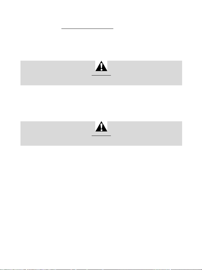
12/24
EINRICHTEN DES RENNLENKRADS FÜR DEN PC*
*PC-Kompatibilität wird von Sony Interactive Entertainment Europe nicht getestet und unterstützt.
Weitere Informationen auf http://support.thrustmaster.com.
AUTOMATISCHE RENNLENKRAD- UND PEDALSET-KALIBRIERUNG
Das Rennlenkrad kalibriert sich automatisch selbst beim Anschluss desselben an die Stromversorgung
und den USB-Anschluss an der Konsole.
Während dieser Phase dreht sich der Lenkkranz schnell nach rechts und links und deckt dabei einen
Rotationswinkel von 1080° ab. Danach stoppt der Lenkkranz in der mittigen Position.
Berühren Sie das Rennlenkrad niemals während der Kalibrierungsphase
(Dies kann zu Kalibrierungsfehlern und/oder Verletzungen führen.)
WARNUNG:
AUTOMATISCHE KALIBRIERUNG DES PEDALSETS
Verbinden/Trennen Sie das Pedalset niemals mit/von der Rennlenkradbasis, wenn diese mit der
Konsole verbunden ist oder während eines Spiels. Dies kann zu Kalibrierungsfehlern führen. Schließen
Sie das Pedalset ausschließlich nur an das Rennlenkrad an, bevor dieser an der Konsole
angeschlossen ist. Nach der Selbstkalibrierung des Lenkrads und nach dem Spielstart werden die
Pedale nach mehrmaligem Niederdrücken automatisch kalibriert.
Betätigen Sie die Pedale niemals während der Selbstkalibrierung des Lenkrads oder während ein
Spiel geladen wird!! (Dies kann zu Kalibrierungsfehlern führen.)
WARNUNG:
Falls Ihr Rennlenkrad und/oder das Pedalset nicht ordnungsgemäß funktionieren oder die
Kalibrierung nicht korrekt zu sein scheint:
Schalten Sie Ihre Konsole aus. Trennen Sie das Rennlenkrad komplett von der Konsole. Schließen Sie
die Kabel (auch Netz- und Pedalset-Kabel) erneut an. Starten Sie dann Ihre Konsole und das Spiel neu.
INTERNER TEMPERATUR-MESSFÜHLER
Das Kühlsystem des Lenkrads besteht aus einem Kühlkörper und einem Lüfter.
• Ein Thermostat überwacht die interne Temperatur des Lenkrads.
• Wenn Sie das Lenkrad in einem Spiel benutzen:
- Beginnt der Lüfter zu arbeiten, wenn das Lenkrad eine bestimmte Temperatur erreicht hat (nach
ein paar Minuten, je nach der Stärke der benutzten Force Feedback Effekte).
- Die Leistung der Force Feedback Effekte verringert sich automatisch, sobald das Rad ein viel
höheres Temperaturniveau (zum Schutz des Motors) erreicht. Die Leistung dieser Effekte erhöht
sich automatisch, sobald die Temperatur leicht abnimmt.
• Nach dem Spielen: Während der Abkühlungsphase des Motors läuft der Lüfter weiter, bis die
Temperatur unter den Beginn der Startstufe des Lüfters abgesunken ist. Ihr Lenkrad wurde deshalb
so gestaltet, um eine Kühlung zu fördern und zu erleichtern und um den Motor zu schützen.
• (dies kann zwischen 5 bis 45 Minuten dauern und ist abhängig von der Temperatur, die durch die
Nutzung des Lenkrads im Spi el erreicht wurde).
Page 62
13/24
GAS- UND KUPPLUNGSPEDALE
Farbe der MODE Leuchtanzeige (6)
NORMAL
ROT
VERTAUSCHT
GRÜN
MODE-BUTTON UND LEUCHTANZEIGE (6)
MODE-Button für das Pedalset
Sie können die Gas- und Kupplungspedale elektronisch vertauschen.
Um dies zu bewerkstelligen, drücken Sie einfach den MODE-Button (6) für 2 Sekunden.
Der interne Speicher des Rennlenkrads speichert, ob die Pedale vertauscht wurden oder nicht.
Andere Hinweise für den MODE-Button
Um mehr über den MODE-Button und die Leuchtanzeige zu erfahren, besuchen Sie bitte die Website
http://support.thrustmaster.com. Dann klicken Sie auf Lenkräder / T300 RS und wählen dann
Benutzerhandbuch oder FAQ aus.
HILFE UND HÄUFIG GESTELLTE FRAGEN (in diesem Handbuch nicht
enthalten)
Gehen Sie bitte auf http://support.thrustmaster.com. Dann klicken Sie auf Lenkräder / T300 RS
und wählen dann Benutzerhandbuch oder FAQ aus.
Page 63
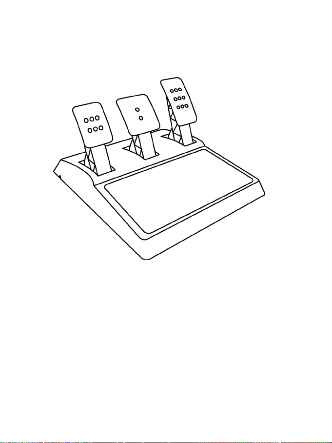
14/24
T3PA – GT EDITION-PEDALSET
Page 64
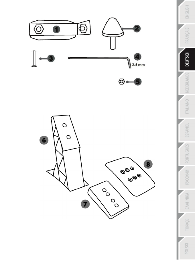
15/24
1 Metallhalterung für den konischen Stop
3 Befestigungsschraube für Metallträger
4 2.5 mm Inbusschlüssel (inklusive)
6 Pedalstange
8 Pedalkopf aus Metall
TECHNISCHE MERKMALE
(standardmäßig nicht montiert)
2 Konischer Stop
5 Positions-Stellmutter für konischen Stop
7 Plastik-Halterung
Page 65
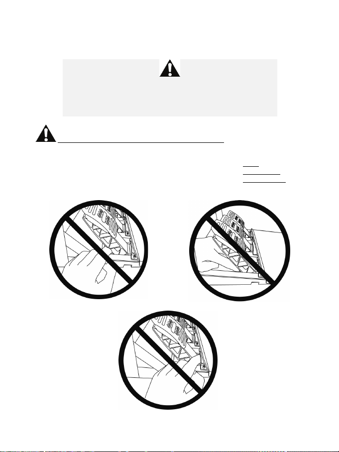
16/24
ACHTUNG
NIE
NIE
NIE
Bevor Sie dieses Produkt benutzen, lesen Sie bitte diese Dokumentation sorgfältig durch und bewahren
diese sicher auf, falls Sie später etwas nachlesen müssen.
Benutzen Sie das Pedalset aus Sicherheitsgründen niemals barfuß
THRUSTMASTER® LEHNT JEDWEDE HAFTUNG IM FALLE EINER
VERLETZUNG DURCH DAS PEDALSET DURCH NUTZUNG DESSELBEN
Achtung – Quetschgefahr am Pedalset während des Spielens
* Bewahren Sie das Pedalset außerhalb der Reichweite von Kindern auf.
* Bringen Sie während des Spielens niemals Ihre Finger auf oder in die Nähe der Seiten der Pedale.
* Bringen Sie während des Spielens niemals Ihre Finger auf oder in die Nähe der Pedalrückseite.
* Bringen Sie während des Spielens niemals Ihre Finger auf oder in die Nähe der Pedalvorderseite.
oder wenn Sie nur Socken tragen.
OHNE SCHUHWERK AB.
Page 66
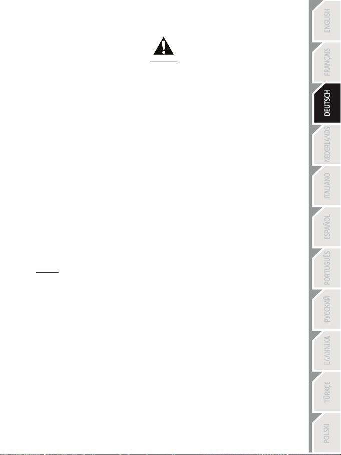
17/24
AUTOMATISCHE KALIBRIERUNG DER PEDALE
- Trennen oder verbinden Sie das Pedalset niemals von/mit der Basis, wenn diese an das PS3™-
oder das PS4™-System angeschlossen ist oder während des Spielverlaufs, um
Kalibrierungsprobleme zu vermeiden.
= Schließen Sie das Pedalset immer an das Lenkrad an, bevor dieses mit einem PS3™- oder einem
PS4™-System verbunden wird.
- Nach der Selbstkalibrierung des Lenkrads und zu Beginn eines Spiels, kalibrieren sich die Pedale
selbstständig nachdem diese einige Male betätigt wurden.
- Drücken Sie niemals die Pedale während der Selbstkalibrierung des Lenkrads oder beim
Spielstart, um Kalibrierungsprobleme zu vermeiden.
- Falls die Pedale nicht korrekt funktionieren oder nicht ordnungsgemäß kalibriert zu sein scheinen:
Schalten Sie Ihre Konsole aus. Trennen Sie Ihr Lenkrad völlig von derselben und schließen
danach alle Kabel (inkl. Netzkabel und Pedalset-Kabel) wieder an. Schalten Sie Ihre Konsole ein
und starten Sie Ihr Spiel erneut.
WICHTIG:
EINBAU DES PEDALSETS IN EIN COCKPIT
- Montieren Sie das Pedal-Set durch die darunterliegenden kleinen Gewindebohrungen.
- Drehen Sie zwei M6 Schrauben (nicht enthalten) durch die Cockpit-Ablage in die beiden kleinen
Schraubgewinde unterhalb des Pedalsets ein.
Wichtig: Die Länge der Schrauben sollte die Dicke der Ablage plus zusätzlich 10 mm nicht
überschreiten. Längere Schrauben könnten die internen Komponenten des Pedalsets beschädigen.
Page 67

18/24
ANPASSEN DES PEDALSETS
Niedrige Position (voreingestellt)
Hohe Position
Jedes der drei Pedale umfaßt:
- Einen Metallkopf (8) mit mehreren Bohrungen (neun für das Gas – zwei für die Bremse – sechs für
die Kupplung).
- Eine Plastik-Halterung (7) mit vier Bohrungen, die zwischen dem Kopf und der Stange plaziert
wird.
- Eine Pedalstange (6) mit zwei Bohrungen.
ACHTUNG: Um jedwede Kalibrierungsprobleme zu vermeiden, stellen Sie sicher, daß das
USB-Kabel des Lenkrads von dem PS3™- oder dem PS4™-System getrennt ist, bevor Sie
Anpassen der HÖHE des Gaspedals
- Benutzen Sie den beigelegten 2,5 mm Inbusschlüssel (4), um die beiden Schrauben, die den
Pedalkopf aus Metall (8) und dessen Plastik-Halterung (7) halten, loszuschrauben.
- Wählen Sie Ihre bevorzugte Höhe und setzen dann die Schrauben wieder ein. Ziehen Sie diese
fest, bis der Pedalkopf aus Metall (8) und dessen Plastik-Halterung (7) wieder festsitzen.
irgendwelche Anpassungen Ihres Pedalsets vornehmen.
Page 68
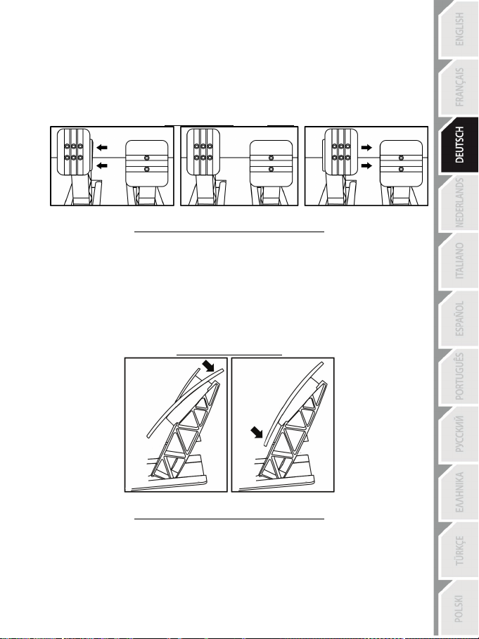
19/24
Anpassen des ZWISCHENRAUMES der drei Pedale
- Benutzen Sie den beigelegten 2,5 mm Inbusschlüssel (4), um die beiden Schrauben, die den
Pedalkopf aus Metall (8) und dessen Plastik-Halterung (7) halten, loszuschrauben.
- Wählen Sie Ihre bevorzugte Position (mehr links, in der Mitte oder mehr nach rechts) und setzen
dann die Schrauben wieder ein. Ziehen Sie diese fest, bis der Pedalkopf aus Metall (8) und
dessen Plastik-Halterung (7) wieder festsitzen.
Zum Beispiel beim Kupplungspedal:
Linke Position Mittige Position (voreingestellt) Rechte Position
Anzahl der möglichen Abstandspositionen pro Pedal:
- Drei für das Gaspedal
- Drei für die Kupplung
Anpassen der NEIGUNG
- Benutzen Sie den beigelegten 2,5 mm Inbusschlüssel (4), um die beiden Schrauben, die den
Pedalkopf aus Metall (8) und dessen Plastik-Halterung (7) halten, loszuschrauben.
- Drehen Sie die Plastikhalterung (7) um 180° und setzen dann die Schrauben wieder ein. Ziehen
Sie diese fest, bis der Pedalkopf aus Metall (8) und dessen Plastik-Halterung (7) wieder
festsitzen.
Zum Beispiel beim Gaspedal:
Weniger geneigte Position Geneigtere Position (voreingestellt)
Anzahl der möglichen Neigungspositionen pro Pedal:
- Zwei für das Gaspedal
- Zwei für die Bremse
- Zwei für die Kupplung
Page 69

20/24
Montage des konischen Stops (“CONICAL RUBBER BRAKE” Mod)
Die Modifizierung (oder “Mod”) ist nicht unbedingt erforderlich und ist standardmäßig nicht montiert.
Das bedeutet, daß die Bremse auch ohne diese Mod bestens funktioniert.
Diese Mod verschafft Ihnen ein anderes Gefühl und einen anderen Widerstand beim Bremsen.
Es liegt bei Ihnen, diese nach Ihrem Belieben zu montieren.
- Schrauben Sie den konischen Stop (2) in dessen Metallhalterung (1).
- Drehen Sie die Positions-Stellmutter (5) von unten auf das Gewinde des konischen Stops.
- Positionieren Sie die Einheit auf der Rückseite der Bremspedalstange.
Page 70
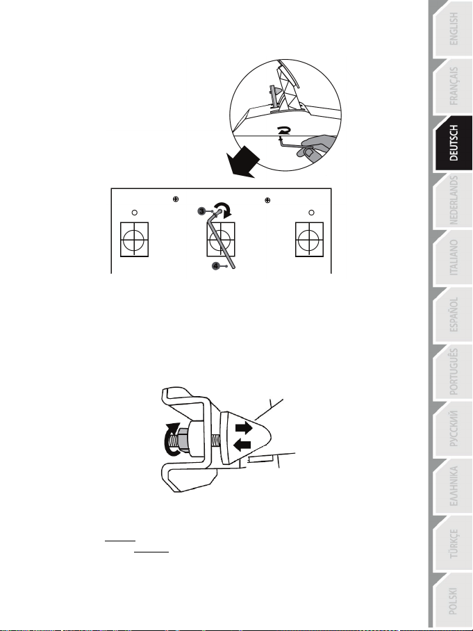
21/24
- Benutzen Sie den beigefügten 2.5 mm Inbusschlüssel (4), um die Einheit mittels der
Befestigungsschraube (3) und dem kleinen Schraubgewinde an der Unterseite des Pedalsets zu
montieren.
Die “CONICAL RUBBER BRAKE” Mod ist nun montiert!
Anpassen des HUBS und der STÄRKE des Widerstands der Bremse
Durch leichtes Losdrehen der Mutter (5) können Sie den Bremswiderstand verstärken, indem Sie
den konischen Stop (2) näher an die Rückseite der Bremspedalstange herausdrehen (falls nötig,
verwenden Sie einen 14-mm-Maulschlüssel oder eine Zange, um die Mutter in der gewählten
Position wieder anzuziehen). Je näher der konische Stop an der Bremspedalstange sitzt, desto
stärker wird der Bremswiderstand.
Bitte beachten: Wenn der konische Stop sehr nahe an der Bremspedalstange sitzt, könnten Sie
Schwierigkeiten zum Erreichen des maximalen Kalibrierungswertes bekommen. Sollte dies der Fall
sein:
* Drücken Sie langsam sehr hart auf das Bremspedal, um den Maximalwert zu erreichen (falls
nötig, stellen Sie sich ganz kurz auf das Pedal - nur für eine Sekunde) und geben dann das Pedal
wieder frei; oder aber
* Drehen den konischen Stop etwas ein, um mehr Abstand von der Bremspedalstange zu erhalten.
Page 71

22/24
Kunden-Garantie-Information
Guillemot Corporation S.A. mit Hauptfirmensitz in Place du Granier, B.P. 97143, 35571 Chantepie,
France (fortfolgend “Guillemot”) garantiert Kunden weltweit, daß dieses Thrustmaster Produkt frei
von Mängeln in Material und Verarbeitung für eine Gewährleistungsfrist ist, die mit der Frist für eine
Mängelrüge bezüglich des Produktes übereinstimmt. In den Ländern der Europäischen Union
entspricht diese einem Zeitraum von zwei (2) Jahren ab Kaufdatum des Thrustmaster Produktes. In
anderen Ländern entspricht die Gewährleistungsfrist der zeitlichen Begrenzung für eine Mängelrüge
bezüglich des Thrustmaster Produktes in Übereinstimmung mit anwendbarem Recht des Landes, in
dem der Kunde zum Zeitpunkt des Erwerbs eines Thrustmaster Produktes wohnhaft ist. Sollte eine
entsprechende Regelung in dem entsprechenden Land nicht existieren, umfasst die
Gewährleistungspflicht einen Zeitraum von einem (1) Jahr ab dem originären Kaufdatum des
Thrustmaster Produktes.
Sollten bei dem Produkt innerhalb der Gewährleistungsfrist Defekte auftreten, kontaktieren Sie
unverzüglich den technischen Kundendienst, der die weitere Vorgehensweise anzeigt. Wurde der
Defekt bestätigt, muß das Produkt an die Verkaufsstelle (oder an eine andere Stelle, je nach
Maßgabe des technischen Kundendienstes) retourniert werden.
Im Rahmen dieser Garantie sollte das defekte Produkt des Kunden, je nach Entscheidung des
technischen Kundendienstes, entweder ausgetauscht oder repariert werden. Sollte während der
Garantiezeit das Thrustmaster Produkt einer derartigen Instandsetzung unterliegen und das
Produkt während eines Zeitraums von mindestens sieben (7) Tagen nicht benutzbar sein, wird
diese Zeit der restlichen Garantiezeit hinzugefügt. Diese Frist läuft ab dem Zeitpunkt, an dem der
Wunsch des Verbrauchers bezüglich einer Intervention vorliegt oder ab dem Tag, an dem das
fragliche Produkt zur Instandsetzung zur Verfügung steht, falls das Datum, an dem das Produkt zur
Instandsetzung zur Verfügung steht, dem Datum des Antrags auf Intervention nachfolgt. Wenn nach
geltendem Recht zulässig, beschränkt sich die volle Haftung von Guillemot und ihrer
Tochtergesellschaften auf die Reparatur oder den Austausch des Thrustmaster Produktes (inklusive
Folgeschäden). Wenn nach geltendem Recht zulässig, lehnt Guillemot alle Gewährleistungen der
Marktgängigkeit oder Eignung für einen bestimmten Zweck ab.
Der Gewährleistungsanspruch verfällt: (1) Falls das Produkt modifiziert, geöffnet, verändert oder ein
Schaden durch unsachgemäßen oder missbräuchlichen Gebrauch hervorgerufen wurde, sowie
durch Fahrlässigkeit, einen Unfall, Verschleiß oder irgendeinem anderen Grund – aber nicht durch
Material- oder Herstellungsfehler (einschließlich, aber nicht beschränkt auf, die Kombination der
Thrustmaster Produkte mit ungeeigneten Elementen, insbesondere Netzteile, Akkus, Ladegeräte,
oder andere Elemente, die von Guillemot für dieses Produkt nicht mitgeliefert wurden); (2) Falls das
Produkt für eine andere Nutzung als zum privaten Hausgebrauch, einschließlich für professionelle
oder kommerzielle Zwecke (z. B. Spielhallen, Training, Wettkämpfe) verwendet wird; (3) Im Falle
der Nichteinhaltung der durch den technischen Support erteilten Anweisungen; (4) Durch Software.
Die besagte Software ist Gegenstand einer speziellen Garantie; (5) Bei Verbrauchsmaterialien
(Elemente, die während der Produktlebensdauer ausgetauscht werden, wie z. B. Einwegbatterien,
Ohrpolster für ein Audioheadset oder für Kopfhörer); (6) Bei Accessoires (z. B. Kabel, Etuis,
Taschen, Beutel, Handgelenk-Riemen); (7) Falls das Produkt in einer öffentlichen Versteigerung
verkauft wurde.Diese Garantie ist nicht übertragbar.
Die Rechte des Kunden in Übereinstimmung mit anwendbarem Recht bezüglich des Verkaufs auf
Konsumgüter im Land der/der Kunden/Kundin wird durch diese Garantie nicht beeinträchtigt.
Page 72

23/24
Zusätzliche Gewährleistungsbestimmungen
Während der Garantiezeit bietet Guillemot grundsätzlich keine Ersatzteile an, da der technische
Kundendienst der einzige autorisierte Partner zum Öffnen und/oder Instandsetzen jedweden
Thrustmaster-Produkts ist (mit Ausnahme von irgendwelchen Instandsetzungsprozeduren, die der
Kunde nach Maßgabe des technischen Kundendienstes und durch schriftliche Instruktionen sowie
der Zurverfügungstellung des/der eventuell erforderlichen Ersatzteil(s)(e) selbst in der Lage ist
durchzuführen – zum Beispiel aufgrund der Einfachheit und einer nicht erforderlichen
Geheimhaltung des Instandsetzungsverfahrens).
Aufgrund seiner Innovationszyklen und um sein Know-how und seine Geschäftsgeheimnisse zu
schützen, bietet Guillemot grundsätzlich keine Instandsetzungs-Benachrichtigung oder Ersatzteile
für alle Thrustmaster Produkte an, deren Garantiezeit abgelaufen ist.
Haftung
Wenn nach dem anwendbaren Recht zulässig, lehnen Guillemot Corporation S.A. (fortfolgend
"Guillemot") und ihre Tochtergesellschaften jegliche Haftung für Schäden, die auf eine oder mehrere
der folgenden Ursachen zurückzuführen sind, ab: (1) das Produkt wurde modifiziert, geöffnet oder
geändert; (2) Nichtbefolgung der Montageanleitung; (3) unangebrachte Nutzung, Fahrlässigkeit, Unfall
(z. B. ein Aufprall); (4) normalem Verschleiß; (5) Die Verwendung des Produkts für jedwede andere
Nutzung als zum privaten Hausgebrauch, einschließlich professionelle oder kommerzielle Zwecke (z. B.
Spielhallen, Training, Wettkämpfe). Wenn nach anwendbarem Recht zulässig, lehnen Guillemot und
seine Niederlassungen jegliche Haftung für Schäden, die nicht auf einen Material- oder
Herstellungsfehler in Bezug auf das Produkt beruhen (einschließlich, aber nicht beschränkt auf, etwaige
Schäden, die direkt oder indirekt durch Software oder durch die Kombination der Thrustmaster
Produkte mit ungeeigneten Elementen, insbesondere Netzteile, Akkus, Ladegeräte, oder andere
Elemente, die von Guillemot für dieses Produkt nicht geliefert wurden), ab.
TECHNISCHER SUPPORT
http://support.thrustmaster.com
Page 73

24/24
COPYRIGHT
*
*
© 2017 Guillemot Corporation S.A. Alle Rechte vorbehalten. Thrustmaster® ist eine eingetragene Marke
von Guillemot Corporation S.A.
Für den Verkauf in Europa, Afrika, dem Nahen Osten, Russland, Indien und Ozeanien lizenziert. Zur
exklusiven Nutzung mit PlayStation
®3 und PlayStation®4.
Alle anderen Marken sind im Besitz Ihrer jeweiligen Eigentümer. Illustrationen nicht verbindlich. Inhalte,
Designs und Spezifikationen können ohne vorherige Ankündigung geändert werden und können von
Land zu Land unterschiedlich sein. Hergestellt in China.
Hergestellt und vertrieben von Guillemot Corporation S.A.
HINWEISE ZUM UMWELTSCHUTZ
In der Europäischen Union: Dieses Produkt darf nach Ende seiner Lebensdauer nicht
über den Hausmüll entsorgt werden, sondern muss an einem Sammelpunkt für das
Recycling von elektrischen und elektronischen Geräten abgegeben werden.
Das Symbol auf dem Produkt, der Gebrauchsanleitung oder der Verpackung weist
darauf hin.
Die Werkstoffe sind gemäß ihrer Kennzeichnung wiederverwertbar. Mit der
Wiederverwertung, der stofflichen Verwertung oder anderen Formen von Altgeräten
leisten Sie einen wichtigen Beitrag zum Schutz unserer Umwelt. Bitte erfragen Sie bei
der Gemeindeverwaltung die zuständige Entsorgungsstelle.
Für alle anderen Länder: Bitte beachten Sie die lokalen Entsorgungsrichtlinien/Gesetze bezüglich elektrischen und elektronischen Equipments.
Wichtige Informationen. Die Farben und Verzierungen können abweichen.
Plastikhalterungen und Aufkleber bitte vor der Nutzung des Produktes entfernen.
www.thrustmaster.com
* Nur in der E U und der Türkei anwendbar
Page 74
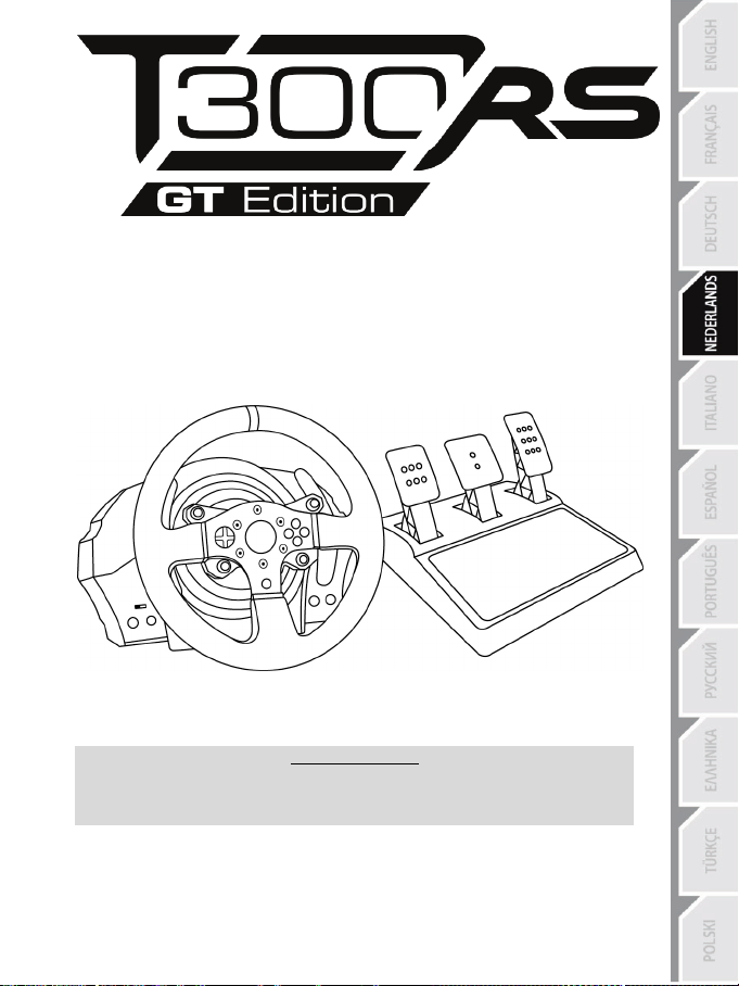
1/24
WAARSCHUWING:
Om er zeker van te zijn dat het T300-racestuur correct werkt met games,
moet u mogelijk de automatische updates voor de games installeren
(beschikbaar wanneer het systeem met internet is verbonden).
Handleiding
Page 75

2/24
TECHNISCHE SPECIFICATIES
1 T300 RS-voet
6 MODE-knop + rood/groen-indicator
7 SELECT/START-knoppen op de PS3™ en
11 Metalen bevestigingsschroef
12 Thrustmaster Quick Release
(kan per land verschillen)
15 USB-kabel en -connector voor racestuur
17 Connector voor pedaalset
2 T300 GT-stuur
3 2 sequentiële schakelflippers (Up & Down)
4 Multidirectionele D-Pad
5 Ingebouwde USB-schuifschakelaar voor
PS4™/PS3™
SHARE/OPTIONS-knoppen op de PS4™
8 PS-knop
9 Groot schroefgat (voor
bevestigingssysteem en -schroef)
10 Bevestigingssysteem
13 L3/R3-knoppen
14 Connector voor netstroom (type A of B)
16 Connector voor versnellingsbak
(versnellingsbak wordt apart verk ocht)
Page 76

3/24
Intern, met:
Intern, met:
BELANGRIJK: als u niet weet welk voltage er op het stopcontact staat op de plek waar u het
Extern, met:
HET RACESTUUR AANSLUITEN OP EEN STOPCONTACT: LEES DIT VOORDAT U VERDER GAAT!
Het land waarin het racestuur is aangeschaft, is bepalend voor het soort netvoeding dat het stuur
gebruikt. Mogelijke soorten netvoeding:
* een voedingseenheid gemonteerd in de voet van het racestuur met een connector van het
type A.
* een kabel voor netstroom van 220-240 V.
= alleen compatibel met een netspanning van 220-240 V.
Sluit de 220-240 V kabel nooit aan
op een 100-130 V stopcontact!!!
Sluit deze kabel nooit aan op een netstroomadapter!!!
* een voedingseenheid gemonteerd in de voet van het racestuur met een connector van het
type A.
* een kabel voor netstroom van 100-125 V.
= alleen compatibel met een netspanning van 100-125 V.
Sluit de 100-125 V kabel nooit aan
op een 220-240 V stopcontact!!!
Sluit deze kabel nooit aan op een netstroomadapter!!!
racestuur wilt gebruiken, neem dan contact op met een plaatselijke elektriciteitsleverancier.
* een externe voedingseenheid met een connector van het type B.
* een kabel voor de voeding.
= compatibel met alle netspanningen van 110-240 V.
Page 77
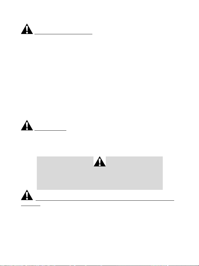
4/24
WAARSCHUWINGEN
Lees, voordat u dit product gebruikt, deze handleiding zorgvuldig door en bewaar hem om eventueel op
een later tijdstip te kunnen raadplegen.
Waarschuwing – Elektrische schok
* Berg dit product op een droge plek op, uit de zon en stofvrij.
* Trek nooit te hard aan een kabel of connector en zorg dat er geen knikken in kabels komen.
* Mors geen vloeistoffen op het product of op een connector.
* Veroorzaak geen kortsl uiting.
* Haal het product nooit uit elkaar, gooi het niet in het vuur en stel het niet bloot aan hoge temperaturen.
* Gebruik geen andere netstroomkabel dan de kabel meegeleverd bij het racestuur.
* Gebruik de netstroomkabel nooit als de kabel, de stekkers of de connectoren zijn beschadigd,
gespleten of gebroken.
* Controleer dat de netstroomkabel correct is aangesloten op het stopcontact en correct is aangesloten
op de achterzijde van de voet van het racestuur.
* Maak het stuur niet open. Er bevinden zich geen door de gebruiker te onderhouden of repareren
onderdelen in. Alle reparaties dienen te worden uitgevoerd door de fabrikant, haar bevoegde
vertegenwoordiger of een gekwalificeerd technicus.
* Gebruik alleen door de fabrikant goedgekeurde hulpstukken en accessoires.
* Als het racestuur zich vreemd gedraagt, bijvoorbeeld door rare geluiden te maken, heet te worden of te
stinken, stop dan onmiddellijk met het gebruik, haal de stekker uit het stopcontact en maak alle andere
kabels los.
* Als het racestuur langere tijd niet wordt gebruikt, haal dan de stekker uit het stopcontact.
Ventilatieopeningen
Blokkeer nooit de ventilatieopeningen op de voet van het stuur. Aanwijzingen voor optimale ventilatie:
* Plaats de voet van het stuur minimaal 10 cm van een muur.
* Plaats de voet niet in een krappe ruimte.
* Leg nooit iets over de voet heen.
* Zorg dat de ventilatieopeningen stofvrij blijven.
Om veiligheidsredenen mogen de pedalen nooit met blote voeten worden
bediend of met alleen sokken aan.
THRUSTMASTER® WIJST ELKE VERANTWOORDELIJKHEID AF IN GEVAL
VAN LETSEL ALS GEVOLG VAN HET GEBRUIK VAN DE PEDAALSET
ZONDER SCHOENEN AAN.
Waarschuwing – Mogelijk letsel ten gevolge van Force Feedback en repetitieve
bewegingen
Gamen met een Force Feedback-stuur kan leiden tot pijn in de gewrichten of de spieren. Hoe
voorkomt u problemen:
* Vermijd langdurige gamesessies.
* Neem na elk uur gamen een pauze van 10 tot 15 minuten.
* Stop met gamen bij last van vermoeidheid of pijn in handen, polsen, armen, voeten of benen, en rust
een paar uur voordat u weer verder gaat met gamen.
Page 78
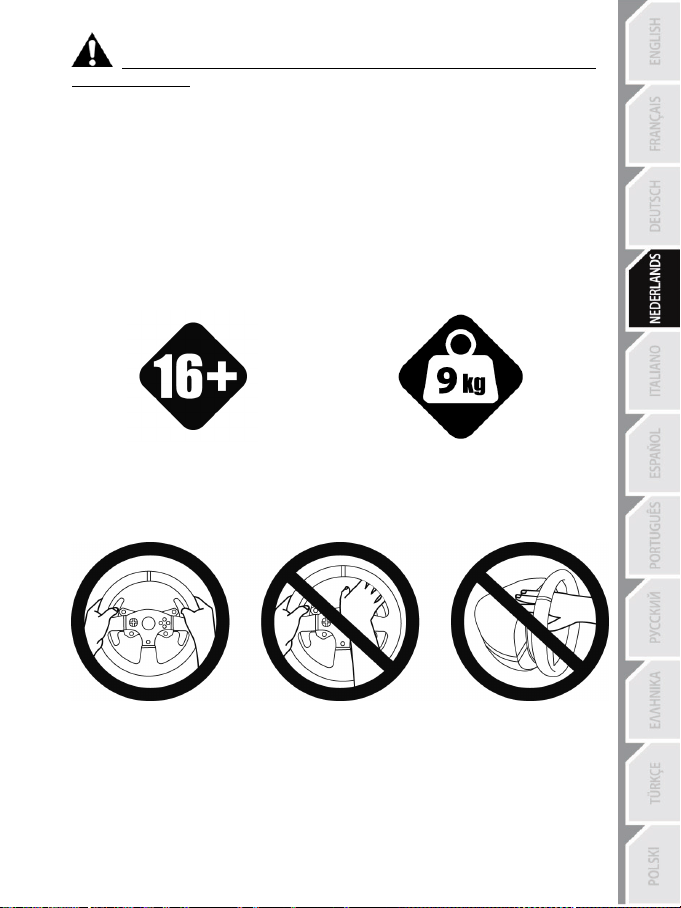
5/24
van 16 jaar of ouder
Waarschuwing – Mogelijk letsel ten gevolge van Force Feedback en repetitieve
bewegingen (vervolg)
* Stop al het gamen als de hierboven beschreven symptomen van pijn of ongemak blijven aanhouden
tijdens het gamen en raadpleeg een huisarts.
* Houd het stuur, de voet en de pedaalset buiten het bereik van kinderen.
* Houd tijdens het gamen altijd twee handen aan het stuur op de juiste stand en laat het stuur nooit
helemaal los.
* Zorg er tijdens het gamen voor dat handen of vingers nooit in de buurt van of onder de pedalen of de
pedaalset komen.
* Steek tijdens het kalibreren en gamen nooit een vinger, hand of arm door de openingen van het
racestuur.
* Zorg er voor dat de voet van het racestuur stevig vast zit, zoals beschreven in deze handleiding.
ZWAAR PRODUCT
Product mag alleen verplaatst worden door
gebruikers
ALTIJD NOOIT NOOIT
Wees voorzichtig en laat het product niet op
uzelf of iemand anders vallen!
Page 79
6/24
Waarschuwing – Pedaalset beknellingsgevaar bij gebruik
* Houd de pedaalset buiten het bereik van kinderen.
* Houd tijdens het gamen nooit uw vingers op of in de buurt van de zijkanten van de pedalen.
* Houd tijdens het gamen nooit uw vingers op of in de buurt van de achterkant van de pedalen.
* Houd tijdens het gamen nooit uw vingers op of in de buurt van de voorkant van de pedalen.
NOOIT NOOIT NOOIT
Waarschuwing – Pedaalset beknellingsgevaar bij gebruik
* Berg de pedaalset op een veilige plaats op, buiten het bereik van kinderen.
DE FIRMWARE VAN HET RACESTUUR BIJWERKEN
De firmware in de voet van het racestuur kan worden bijgewerkt naar een nieuwere verbeterde versie
wanneer een dergelijke versie beschikbaar komt.
Om de huidige versie van de firmware van het racestuur weer te geven en deze bij te werken indien
gewenst: ga op een pc naar http://support.thrustmaster.com. Klik op Racesturen / T300 RS,
selecteer Firmware en volg de instructies voor het downloaden en installeren.
Belangrijke opmerking:
Op een pc moet de USB-schuifschakelaar (5) op de voet van het racestuur altijd in de stand
PS3™ staan.
Page 80
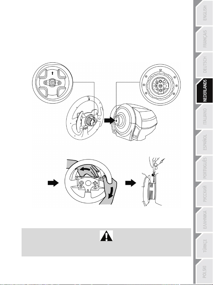
7/24
HET RACESTUUR INSTALLEREN OP DE VOET
Positioneer de connectoren met behulp van de pijlen:
Connector op voet (1): pijl die omhoog wijst
Connector op stuur (2): pijl die omhoog wijst
Draai zodra de connectoren correct zijn gepositioneerd de ring van de Thrustmaster Quick Release (12)
op zijn plaats tegen de wijzers van de klok in terwijl u het racestuur vasthoudt (2) .
Draai vervolgens de ring zo strak mogelijk vast door deze op zijn plaats te houden en het stuur met de
wijzers van de klok mee te draaien.
Zodra u het racestuur hebt geïnstalleerd, draait u het 180° om (kijkend naar het stuur, moet het GT-logo
nu ondersteboven staan) voor toegang tot de kleine bevestigingsschroef onder op de Thrustmaster Quick
Release (12). Gebruik een grote kruiskopschroevendraaier om de kleine bevestigingsschroef met de
wijzers van de klok mee vast te draaien (gebruik geen overmatige kracht).
Draai bij het gebruik van een kruiskopschroevendraaier de kleine bevestigingsschroef niet te vast
Stop met het aandraaien van de schroef zodra u enige weerstand voelt.
aan!
Page 81
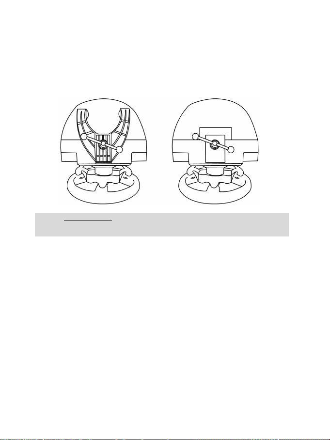
8/24
HET RACESTUUR BEVESTIGEN
WAARSCHUWING: draai de schroef nooit in het racestuur zonder het
(Daarmee kunt u het racestuur beschadigen).
Het racestuur op een tafel of werkblad bevestigen
1. Plaats het racestuur op een tafel of een ander horizontaal, vlak en stabiel oppervlak.
2. Plaats de bevestigingsschroef (11) in het bevestigingssysteem (10) en draai de schroef aan
(tegen de klok in) zodat deze vast komt te zitten in het schroefgat (9) onder het racestuur en het
stuur volledig stabiel is.
ALTIJD NOOIT
bevestigingssysteem!
Page 82
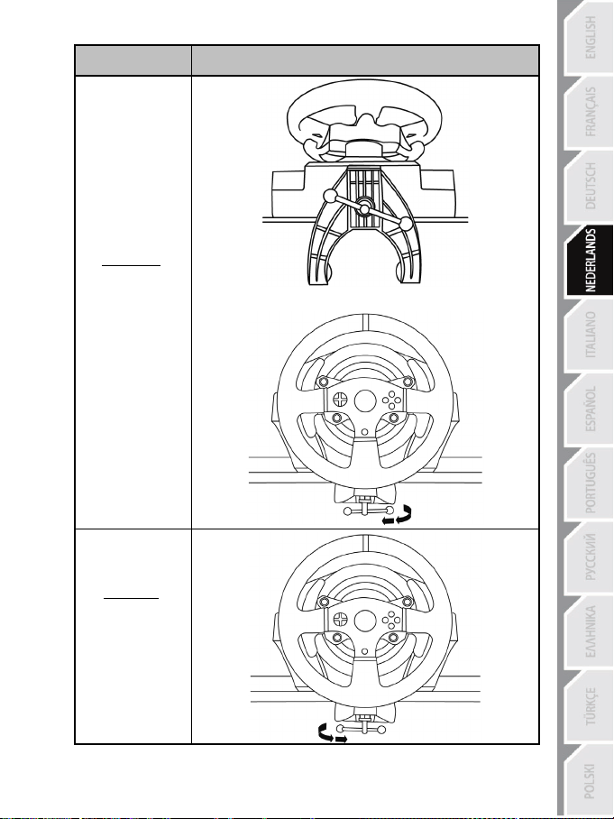
9/24
BEVESTIGEN /
VERWIJDEREN
Vastdraaien:
Draai de schroef
linksom vast (tegen
de wijzers van de
klok in).
RICHTING
Losdraaien:
Draai de schroef
rechtsom los (met de
wijzers van de klok
mee).
Page 83

10/24
De voet van het racestuur aan een cockpit bevestigen
1. Plaats de voet van het racestuur op het cockpitpaneel.
2. Draai twee M6-schroeven (niet meegeleverd) door het cockpitpaneel en in de twee kleine
schroefgaten aan de onderkant van het racestuur.
Belangrijk: de M6-schroeven mogen niet langer zijn dan de dikte van het paneel + 12 mm.
Langere schroeven kunnen de componenten in de voet van het racestuur beschadigen.
3. Zet indien nodig het standaardbevestigingssysteem vast door de bevestigingsschroef in het
grote schroefgat te draaien.
MAPPING VOOR PLAYSTATION®3 EN PLAYSTATION®4
Page 84
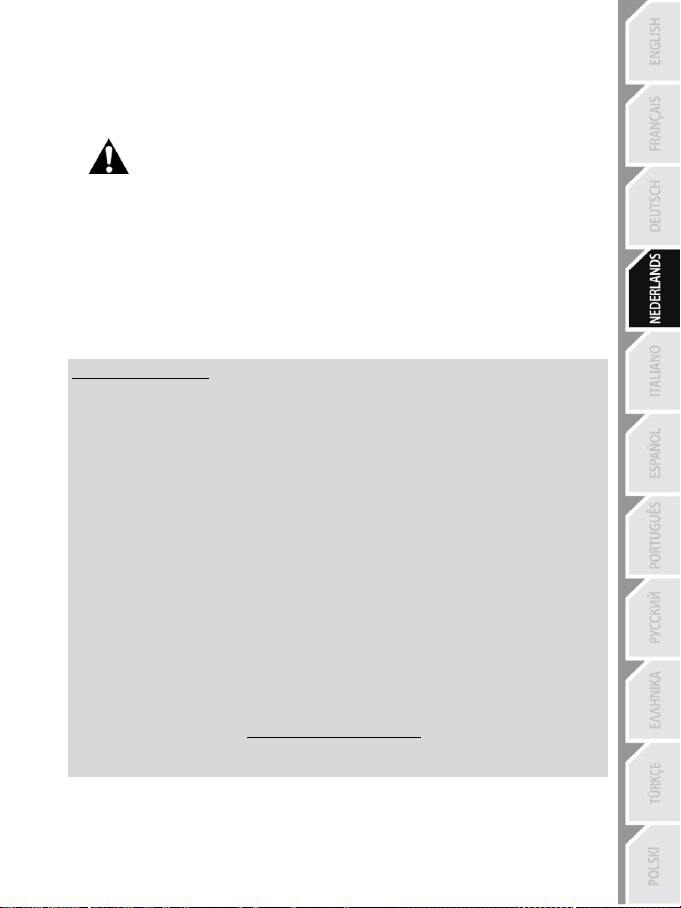
11/24
HET RACESTUUR GEREED MAKEN VOOR DE PLAYSTATION®3 OF
PLAYSTATION®4
1. Sluit de pedaalset aan op de connector (17) aan de achterkant van de voet van het racestuur.
2. Sluit de netstroomkabel aan op de connector (14) aan de achterkant van de voet van het racestuur.
3. Sluit de netstroomkabel aan op een stopcontact met de correcte netspanning.
4. Zet de USB-keuzeschakelaar (5) op de voet van het racestuur in de gewenste stand: PS3™ of
5. Sluit de USB-connector (15) van het stuur aan op een van de USB-poorten van de console.
6. Zodra de console stroom krijgt, kalibreert het stuur zichzelf.
7. Als de USB-keuzeschakelaar in de stand PS4™ staat, drukt u op de PlayStation
Nu kan er gespeeld worden!
Belangrijke opmerkingen:
- De USB-keuzeschakelaar (5) op de voet van het racestuur moet altijd op de correcte stand
(PS3™ of PS4™) worden gezet voordat de USB-kabel van het stuur op de console wordt
aangesloten. Als u de stand van de keuzeschakelaar wilt veranderen, koppelt u de USB-kabel
los van de console, verandert u de stand en sluit u de USB-kabel weer aan op de console.
- Op de PlayStation
* Het stuur wordt in de meeste games herkend als een T500RS-stuur.
* Het stuur werkt in compatibele games en in consolemenu's.
* De “PS”-functie op het stuur werkt.
- Op de PlayStation
* Het stuur wordt in de meeste games herkend als een T500RS-stuur.
* Het stuur werkt in compatibele games, maar niet in consolemenu's.
* De “SHARE”- en de “PS”-functie op het stuur werken niet.
- Op de PlayStation
* Vergeet niet op de PS-knop (8) op het stuur te drukken om het stuur te kunnen gebruiken.
* Het stuur wordt in de meeste games herkend als een T300 RS-stuur.
* Het stuur werkt in compatibele games en in consolemenu's.
* De “SHARE”- en de “PS”-functie op het stuur werken.
- De lijst met PlayStation
daarvoor benodigde stand van de USB-keuzeschakelaar (5) is beschikbaar op:
Raadpleeg voor meer informatie over dit onderwerp de sectie HET RACESTUUR
AANSLUITEN OP EEN STOPCONTACT op pagina 3 van deze handleiding.
PS4™.
(8) op het racestuur en gaat u naar uw Sony Entertainment Network account om het stuur te
kunnen gebruiken.
®3 moet de USB-keuzeschakelaar (5) altijd in de stand PS3™ staan:
®4 met de USB-keuzeschakelaar (5) in de stand PS3™:
®4 met de USB-keuzeschakelaar (5) in de stand PS4™:
®3- en PlayStation®4-games die compatibel zijn met de T300 RS en de
®4 op de PS-knop
http://support.thrustmaster.com
(klik op Racesturen / T300 RS / Spellen instellingen).
Deze lijst wordt regelmatig bijgewerkt.
Page 85
12/24
HET RACESTUUR INSTALLEREN OP UW PC*
*PC-compatibiliteit niet getest en niet ondersteund door Sony Interactive Entertainment E urope.
Voor meer informatie, ga naar http://support.thrustmaster.com.
HET RACESTUUR EN DE PEDAALSET AUTOMATISCH KALIBREREN
Het stuur kalibreert zichzelf automatisch wanneer u het stuur op een stopcontact aansluit en de USBconnector van het stuur op de console aansluit.
Tijdens deze kalibratie zal het stuur snel 1080 graden linksom en rechtsom draaien voordat het stopt in
de middenstand.
(Raakt u het stuur toch aan, dan kan dit leiden tot een onjuiste kalibratie en/of persoonlijk letsel).
Tijdens het automatisch kalibreren mag u het stuur niet aanraken.
WAARSCHUWING:
AUTOMATISCH KALIBREREN VAN DE PEDAALSET
Sluit de pedaalset nooit aan op de voet van het racestuur of koppel deze nooit los van de voet terwijl het
is aangesloten op de console of tijdens het gamen. Doet u dit toch, dan kan dat leiden tot een onjuiste
kalibratie.
Sluit altijd eerst de pedaalset aan voordat u het racestuur aansluit op de console.
Nadat de kalibratie van het racestuur gereed is en de game gestart is, zijn de pedalen automatisch
gekalibreerd na een paar keer intrappen.
WAARSCHUWING:
Trap de pedalen nooit in
tijdens het zelfkalibreren van het stuur of tijdens het laden van de game.
(Dit kan leiden tot een onjuiste kalibratie).
Als het racestuur en de pedaalset niet goed werken of niet goed gekalibreerd lijken te zijn:
zet de console uit en koppel alle aansluitingen van het stuur los. Sluit daarna alle kabels weer aan,
inclusief de voedingskabel en de pedaalset, en herstart de console en de game.
INTERNE TEMPERATUURSENSOR
Het stuur wordt gekoeld door een koellichaam en een ventilator.
• De temperatuur van het stuur wordt continu gemeten door een thermostaat.
• Wanneer het stuur wordt gebruikt in een game:
- Het stuur wordt warm en zodra een bepaalde temperatuur is bereikt, slaat de koelventilator aan
(na enkele minuten gamen en afhankelijk van de intensiteit van de Force Feedback-effecten).
- De intensiteit van de Force Feedback-effecten neemt automatisch af als het stuur erg warm
wordt (om de motor te beschermen). De intensiteit van deze effecten neemt automatisch toe
zodra de temperatuur weer iets zakt.
• Na gebruik van het stuur loopt de temperatuur slechts langzaam terug en zal de koelventilator blijven
draaien totdat de gewenste lagere temperatuur is bereikt. De koeling van het racestuur is op deze
wijze ontworpen om alle onderdelen maximaal te beschermen (het nakoelen kan 5 - 45 minuten
duren, afhankelijk van de tijdens het gamen bereikte temperatuur).
Page 86
13/24
GASPEDAAL EN KOPPELINGSPEDAAL
Kleur van de MODE-indicator (6)
NORMAAL
ROOD
VERWISSELD
GROEN
MODE-KNOP EN INDICATOR (6)
MODE-knop voor de pedaalset
Op de pedaalset is het mogelijk de functie van het koppelingspedaal en het gaspedaal te
verwisselen.
Dit doet u door de MODE-knop (6) twee seconden ingedrukt te houden.
De door u ingestelde functie van de pedalen wordt opgeslagen in het interne geheugen van het
racestuur.
Meer functies van de MODE-knop
Meer informatie over de MODE-knop en de indicator vindt u op http://support.thrustmaster.com. Klik
op Racesturen / T300 RS en selecteer vervolgens Handleiding of FAQ.
HELPBESTANDEN EN FAQS (NIET OPGENOMEN IN DEZE HANDLEIDING)
Ga naar http://support.thrustmaster.com. Klik op Racesturen / T300 RS en selecteer vervolgens
Handleiding of FAQ.
Page 87

14/24
T3PA – GT EDITION-PEDAALSET
Page 88

15/24
1 Metalen steun voor conische begrenzer
3 Bevestigingsbout voor metalen steun
4 2,5 mm inbussleutel (meegeleverd)
6 Pedaalarm
8 Metalen pedaal
TECHNISCHE KENMERKEN
(niet geïnstalleerd bij levering)
2 Conische begrenzer
5 Afstelmoer voor conische begrenzer
7 Kunststof pedaalsteun
Page 89

16/24
WAARSCHUWING
NOOIT
NOOIT
NOOIT
Lees, voordat u dit product gebruikt, dit document zorgvuldig door en bewaar het om eventueel op een
later tijdstip te kunnen raadplegen.
Voor uw en andermans veiligheid mag de pedaalset nooit worden gebruikt op
THRUSTMASTER® WIJST ELKE VERANTWOORDELIJKHEID AF IN GEVAL
VAN LETSEL ALS GEVOLG VAN HET GEBRUIK VAN DE PEDAALSET
Waarschuwing – Pedaalset beknellingsgevaar tijdens gamen
* Houd de pedaalset buiten het bereik van kinderen.
* Zorg tijdens gebruik dat vingers of duimen nooit in de buurt van of op de zijkanten van de pedalen
komen.
* Zorg tijdens gebruik dat vingers of duimen nooit in de buurt van of op de achterzijde van de pedalen
komen.
* Zorg tijdens gebruik dat vingers of duimen nooit in de buurt van of op de voorzijde van de pedalen
komen.
blote voeten of met alleen sokken aan.
ZONDER SCHOENEN AAN.
Page 90
17/24
AUTOMATISCHE KALIBRATIE VAN PEDALEN
- Om kalibratieproblemen te vermijden, mag u de pedaalset nooit aansluiten op of loskoppelen van
de voet van het stuur wanneer het stuur is verbonden met het PS3™ of PS4™ systeem, of tijdens
het gamen.
= Sluit de pedaalset altijd eerst aan op het stuur voordat u het stuur aansluit op het PS3™ of PS4™
systeem.
- Zodra het stuur zichzelf heeft gekalibreerd en de game is gestart, kalibreren de pedalen zichzelf
automatisch nadat ze enkele malen zijn ingetrapt.
- Om kalibratieproblemen te vermijden, mag u nooit op de pedalen trappen wanneer het stuur bezig
is met zelfkalibratie of wanneer de game aan het opstarten is,
- Als de pedalen niet correct werken of niet correct gekalibreerd lijken te zijn, schakel dan de
console uit, koppel het stuur volledig los, sluit alle kabels weer aan (inclusief de voedingskabel en
de pedaalsetkabel) en start de console en de game opnieuw op.
BELANGRIJK:
DE PEDAALSET AAN EEN COCKPIT BEVESTIGEN
- Bevestig de pedaalset met behulp van de kleine schroefdraden onderop de pedaalset.
- Schroef twee M6-boutjes (niet meegeleverd) in de pedaalsteunplaat van de cockpit en in de twee
kleine schroefdraden onderop de pedaalset.
Belangrijk: om beschadiging van de interne onderdelen van de pedaalset te voorkomen, mogen de
twee M6-boutjes niet langer zijn dan de dikte van de pedaalsteunplaat van de cockpit plus een extra
10 mm.
Page 91
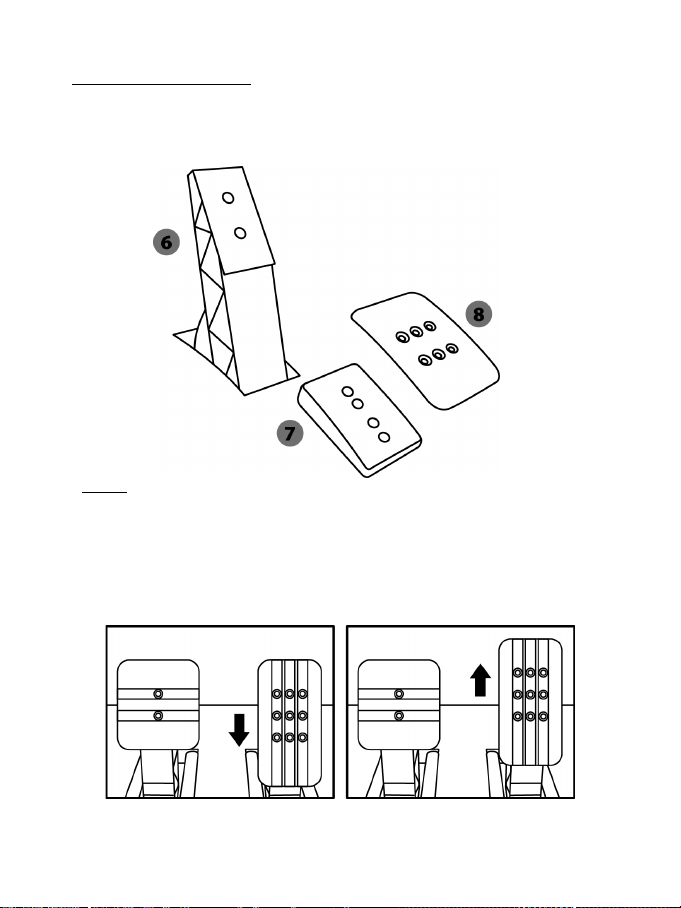
18/24
DE PEDAALSET VERSTELLEN
Elk van de drie pedalen bestaat uit:
- Een metalen pedaal (8) met een aantal gaatjes (negen voor het gaspedaal, twee voor het
rempedaal en zes voor het koppelingspedaal).
- Een kunststof tussenstuk (7) (wordt geplaatst tussen het pedaal en de arm van het pedaal) met
vier gaatjes.
- Een pedaalarm (6) met twee gaatjes.
LET OP: om kalibratieproblemen te vermijden, moet u altijd de USB-kabel tussen stuur en
PS3™ of PS4™ systeem loskoppelen voordat u de pedaalset verstelt.
De HOOGTE van een pedaal afstellen
- Draai met behulp van de meegeleverde 2,5 mm inbussleutel (4) de twee boutjes los waarmee het
pedaal (8) en de steun (7) vast zitten.
- Kies de gewenste pedaalhoogte en zet de twee boutjes weer vast waarmee het pedaal (8) en de
steun (7) vast zitten.
Lage stand (standaard) Hoge stand
Page 92
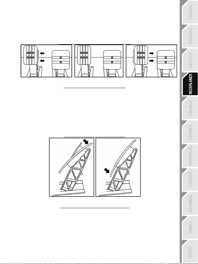
19/24
De RUIMTE afstellen
- Draai met behulp van de meegeleverde 2,5 mm inbussleutel (4) de twee boutjes los waarmee het
pedaal (8) en de steun (7) vast zitten.
- Kies de gewenste pedaalstand (naar links, in het midden of naar rechts) en zet de twee boutjes
weer vast waarmee het pedaal (8) en de steun (7) vast zitten.
Voorbeelden (in dit geval het koppelingspedaal):
Links In het midden (standaard) Rechts
Aantal mogelijke standen van een pedaal:
- Drie voor gaspedaal
- Drie voor koppelingspedaal
De HOEK van een pedaal afstellen
- Draai met behulp van de meegeleverde 2,5 mm inbussleutel (4) de twee boutjes los waarmee het
pedaal (8) en de steun (7) vast zitten.
- Draai de kunststof steun (7) 180° om en zet de twee boutjes weer vast waarmee het pedaal (8) en
de steun (7) vast zitten.
Voorbeelden (in dit geval het gaspedaal):
Kleine hoek Grote hoek (standaard)
Aantal mogelijke hoekstanden van een pedaal:
- Twee voor gaspedaal
- Twee voor rempedaal
- Twee voor koppelingspedaal
Page 93
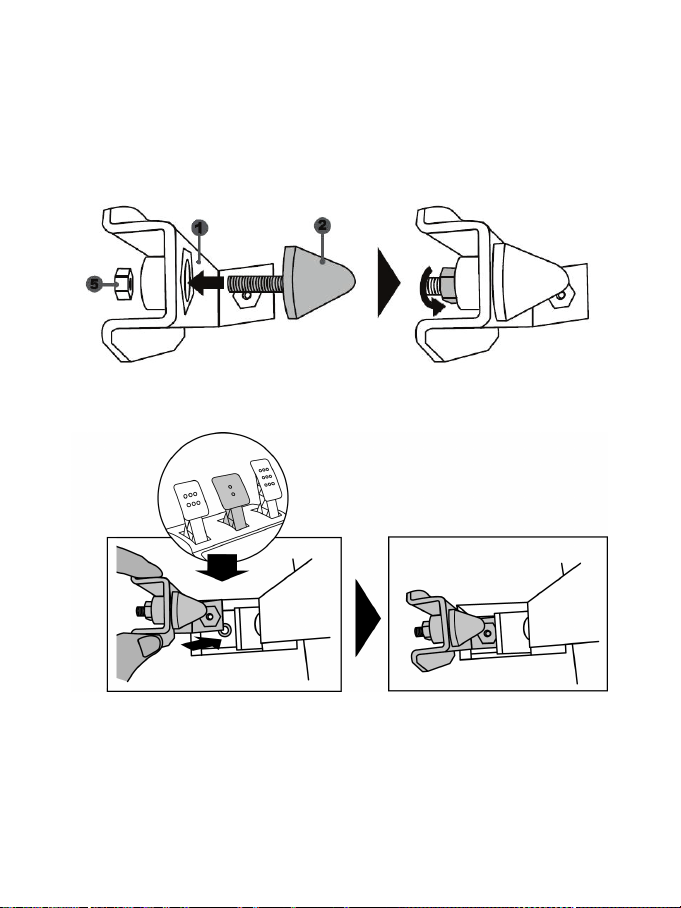
20/24
De conische begrenzer monteren (“CONICAL RUBBER BRAKE” mod)
Deze modificatie (of “mod”) is niet noodzakelijk en is af fabriek niet gemonteerd. Dit betekent dat het
rempedaal ook perfect functioneert als deze mod niet is gemonteerd.
Als u deze mod wel monteert, krijgt u een ander gevoel in het rempedaal.
Het wel of niet monteren van deze begrenzer is dus een kwestie van voorkeur.
- Schroef de conische begrenzer (2) op de metalen steun (1).
- Schroef de afstelmoer (5) op de schroefdraad van de conische begrenzer.
- Plaats de unit achterop de rempedaalarm.
Page 94
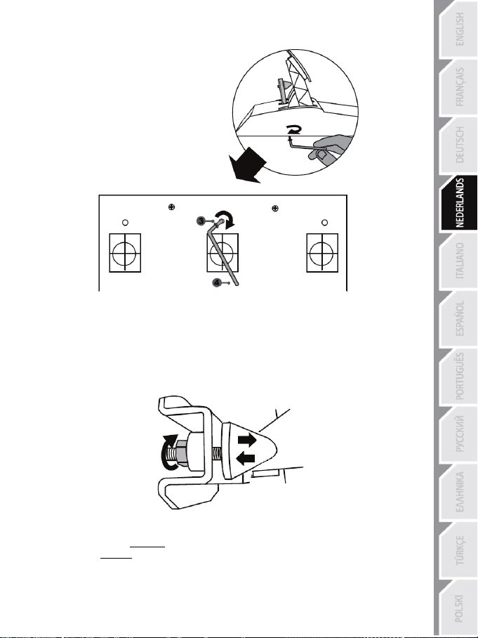
21/24
- Gebruik de meegeleverde 2,5 mm inbussleutel (4) om de unit te monteren met het
bevestigingsboutje (3) en de kleine centrale schroefdraad onderop de pedaalset.
De “CONICAL RUBBER BRAKE”
mod is nu gemonteerd
De SLAG en WEERSTAND van het rempedaal afstellen
Als u meer weerstand in het rempedaal wilt, draait u de moer (5) iets los en plaatst u de begrenzer
(2) iets dichter bij het rempedaal (gebruik indien nodig een 14 mm steek- of ringsleutel, of een tang
om de moer opnieuw vast te draaien en de gewenste stand te fixeren). Hoe dichter de begrenzer
onder het rempedaal ligt, hoe meer weerstand u voelt bij het remmen.
Opmerking: als u de begrenzer heel dicht onder het rempedaal afstelt, wordt het mogelijk lastig om
de maximale kalibratiewaarde te bereiken. Mocht dit het geval zijn:
* Trap het rempedaal langzaam maar heel stevig in om de maximale waarde te bereiken (ga indien
nodig even heel kort (een seconde) op het pedaal staan) en laat dan het pedaal weer omhoog
komen, of
* Zet de conische begrenzer iets verder weg van de arm van het rempedaal.
Page 95

22/24
Informatie met betrekking tot kopersgarantie
Wereldwijd garandeert Guillemot Corporation S.A., het statutair adres gevestigd aan de Place du
Granier, B.P. 97143, 35571 Chantepie, Frankrijk, (hierna te noemen “Guillemot”) aan de de koper dat dit
Thrustmaster-product vrij zal zijn van materiaal- en fabricagefouten gedurende een garantieperiode
gelijk aan de tijd maximaal vereist om een restitutie/vervanging voor dit product te claimen. In landen
van de Europese Unie komt dit overeen met een periode van twee (2) jaar vanaf het moment van
levering van het Thrustmaster-product. In andere landen komt de garantieperiode overeen met de tijd
maximaal vereist om een restitutie/vervanging voor dit Thrustmaster-product te claimen zoals wettelijk is
vastgelegd in het land waarin de koper woonachtig was op de datum van aankoop van het
Thrustmaster-product. Indien een dergelijk claimrecht niet wettelijk is vastgelegd in het betreffende land,
geldt een garantieperiode van één (1) jaar vanaf datum aankoop van het Thrustmaster-product.
Indien u in de garantieperiode een defect meent te constateren aan dit product, neem dan onmiddellijk
contact op met Technical Support die u zal informeren over de te volgen procedure. Als het defect wordt
bevestigd, dient het product te worden geretourneerd naar de plaats van aankoop (of een andere locatie
die wordt opgegeven door Technical Support).
Binnen het gestelde van deze garantie wordt het defecte product van de koper gerepareerd of
vervangen, zulks ter beoordeling van Technical Support. Indien het Thrustmaster- product tijdens de
garantieperiode is onderworpen aan een dergelijk herstel, wordt elke periode van ten minste zeven (7)
dagen waarin het product niet in gebruik is, opgeteld bij de resterende garantieperiode (deze periode
loopt vanaf de datum van verzoek van de consument voor interventie of vanaf de datum waarop het
product in kwestie beschikbaar is gesteld voor herstel als de datum waarop het product ter beschikking
wordt gesteld voor herstel later is dan de datum van het verzoek om interventie). Indien toegestaan door
van toepassing zijnde wetgeving, beperkt de volledige aansprakelijkheid van Guillemot en haar
dochterondernemingen (inclusief de aansprakelijkheid voor vervolgschade) zich tot het repareren of
vervangen van het Thrustmaster-product. Indien toegestaan door van toepassing zijnde wetgeving, wijst
Guillemot elke garantie af met betrekking tot verhandelbaarheid of geschiktheid voor enig doel.
Deze garantie is niet van kracht: (1) indien het product aangepast, geopend of gewijzigd is, of
beschadigd is ten gevolge van oneigenlijk of onvoorzichtig gebruik, verwaarlozing, een ongeluk,
normale slijtage, of enige andere oorzaak die niet gerelateerd is aan een materiaal- of fabricagefout
(inclusief maar niet beperkt tot het combineren van het Thrustmaster-product met enig ongeschikt
element waaronder in het bijzonder voedingsadapters, oplaadbare batterijen, opladers of enig ander
element niet geleverd door Guillemot voor dit product); (2) als het product is gebruikt voor enig ander
doel dan thuisgebruik, zoals maar niet exclusief een professioneel of commercieel doel (bijvoorbeeld
game rooms, training, wedstrijden); (3) indien u zich niet houdt aan de instructies zoals verstrekt door
Technical Support; (4) op software die onder een specifieke garantie valt; (5) op verbruiksartikelen
(elementen die tijdens de levensduur van het product worden vervangen zoals bijvoorbeeld batterijen of
pads van een headset of koptelefoon); (6) op accessoires (zoals bijvoorbeeld kabels, behuizingen,
hoesjes, etui's, draagtassen of polsbandjes); (7) indien het product werd verkocht op een openbare
veiling.
Deze garantie is niet overdraagbaar.
De wettelijke rechten van de koper die in zijn/haar land van toepassing zijn op de verkoop van
consumentproducten worden op generlei wijze door deze garantie beperkt.
Page 96
23/24
TECHNISCHE ONDERSTEUNING
Aanvullende garantiebepalingen
Gedurende de garantieperiode zal Guillemot in principe nooit reserveonderdelen leveren omdat
Technical Support de enige partij is die bevoegd is een Thrustmaster-product te openen en/of te
herstellen (met uitzondering van een herstelprocedure die de klant door Technical Support gevraagd
wordt uit te voeren met behulp van schriftelijke instructies – omdat deze procedure bijvoorbeeld
eenvoudig is en het herstelproces niet vertrouwelijk is – en door het verstrekken aan de consument
van de benodigde onderdelen, indien van toepassing).
Gezien de innovatiecycli en om haar knowhow en handelsgeheimen te beschermen, zal Guillemot in
principe nooit een herstelbeschrijving of reserveonderdelen verstrekken voor een Thrustmaster-product
waarvan de garantieperiode is verstreken.
Aansprakelijkheid
Indien toegestaan door van toepassing zijnde wetgeving, wijzen Guillemot Corporation S.A. (hierna te
noemen “Guillemot”) en haar dochterondernemingen alle aansprakelijkheid af voor enige schade
veroorzaakt door één van de volgende oorzaken: (1) indien het product aangepast, geopend of
gewijzigd is; (2) de montage-instructies niet zijn opgevolgd; (3) oneigenlijk of onvoorzichtig gebruik,
verwaarlozing, een ongeluk (bijvoorbeeld stoten); (4) normale slijtage; (5) het gebruik van het product
voor enig ander doel dan thuisgebruik, zoals maar niet exclusief een professioneel of commercieel doel
(bijvoorbeeld game rooms, training, wedstrijden). Indien toegestaan onder van toepassing zijnde
wetgeving, wijzen Guillemot en haar dochterondernemingen alle aansprakelijkheid af voor enige
schade aan dit product niet gerelateerd aan een materiaal- of fabricagefout (inclusief maar niet beperkt
tot enige schade direct of indirect veroorzaakt door enige software, of door het combineren van het
Thrustmaster-product met enig ongeschikt element waaronder in het bijzonder voedingsadapters,
oplaadbare batterijen, opladers of enig ander element niet geleverd door Guillemot voor dit product).
http://support.thrustmaster.com
Page 97
24/24
COPYRIGHT
*
*
© 2017 Guillemot Corporation S.A. Alle rechten voorbehouden. Thrustmaster® is een geregistreerd
handelsmerk van Guillemot Corporation S.A.
Gelicentieerd voor verkoop in Europa, Afrika, Midden-Oosten, Rusland, India en Oceanië. Voor exclusief
gebruik met PlayStation
®3 en PlayStation®4.
Alle andere handelsmerken zijn het eigendom van hun respectieve eigenaren. Afbeeldingen zijn niet
bindend. Inhoud, ontwerp en specificaties kunnen zonder kennisgeving vooraf worden gewijzigd en
kunnen per land verschillen. Geproduceerd in China.
Geproduceerd en gedistribueerd door Guillemot Corporation S.A.
AANBEVELINGEN VOOR DE BESCHERMING VAN HET MILIEU
In de Europese Unie: Gooi dit product na het einde van de levensduur niet weg met
het normale afval, maar breng het naar het door uw gemeente aangewezen
inzamelpunt voor elektrische en/of computerapparatuur.
Ter herinnering is hiertoe op het product, de gebruikshandleiding of de verpakking
een symbool aangebracht.
De meeste materialen kunnen worden gerecycled. Door recycling en andere
methoden voor verantwoorde verwerking van afgedankte elektrische en
elektronische apparaten kunt u een belangrijke bijdrage leveren aan de
bescherming van het milieu.
Neem contact op met uw gemeente voor informatie over een inzamelpunt bij u in de buurt.
In alle andere landen: houd u aan de plaatselijk milieuwetgeving voor elektrische en elektronische
apparaten.
Bewaar deze informatie. De kleuren en decoraties kunnen variëren.
Plastic bevestigingen en hechtmaterialen moeten van het product worden verwijderd voordat het wordt
gebruikt.
www.thrustmaster.com
*Alleen van toepassing in de EU en Turkije
Page 98
1/24
Manuale d'uso
ATTENZIONE:
Per far sì che il tuo T300 funzioni correttamente con i giochi,
potrebbe rendersi necessario installare gli aggiornamenti automatici dei giochi
(disponibili nel momento in cui il tuo sistema viene collegato a internet).
Page 99
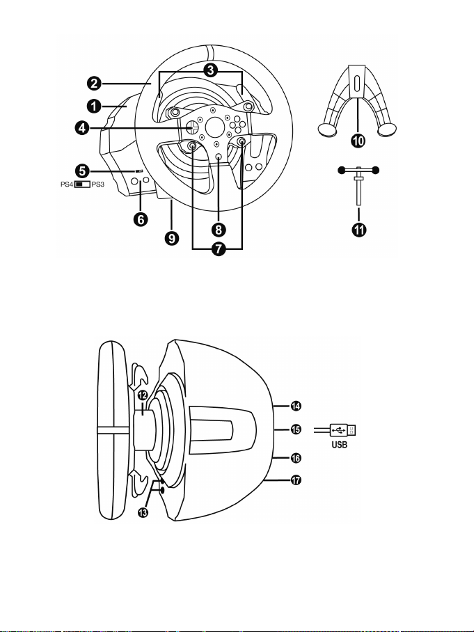
2/24
CARATTERISTICHE TECNICHE
1 Base T300 RS
7 Pulsanti SELECT/START su PS3™ e
11 Vite di fissaggio in metallo
12 Thrustmaster Quick Release
(varia da una nazione all'altr a)
15 Cavo USB e connettore del volante
17 Connettore pedaliera
2 Volante T300 GT
3 2 leve del cambio sequenziali (Up e Down)
4 D-Pad multidirezionale
5 Selettore USB integrato per PS4™/PS3™
6 Pulsante MODE + spia luminosa rosso/verde
SHARE/OPTIONS su PS4™
8 Pulsante PS
9 Ampio foro filettato (per sistema di
aggancio e vite di fissaggio)
10 Sistema di aggancio
13 Pulsanti L3/R3
14 Connettore di alimentazione (tipo A o B)
16 Connettore per cambio
(cambio venduto separatamente)
Page 100
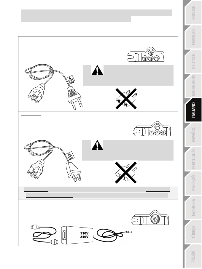
3/24
Interna, con:
Interna, con:
IMPORTANTE: se non conosci il voltaggio della corrente elettrica presente nell'area in cui
Esterna, con:
COLLEGARE IL VOLANTE A UNA PRESA DI CORRENTE: SI PREGA DI LEGGERE ATTENTAMENTE PRIMA DI PROCEDERE!
L'alimentatore del tuo volante varia a seconda della nazione in cui hai acquistato la tua periferica.
L'alimentazione potrebbe essere:
* Un alimentatore collocato direttamente nella base del volante, con un connettore tipo A
* Un cavo di alimentazione da 220-240V
= compatibile solo con correnti elettriche a 220-240V.
Non collegare mai il cavo da 220-240V
a una presa elettrica a 100-130V!
Non collegare mai questo cavo a un adattatore!!!
* Un alimentatore collocato direttamente nella base del volante, con un connettore tipo A
* Un cavo di alimentazione da 100-125V
= compatibile solo con correnti elettriche a 100-125V.
Non collegare mai il cavo da 100-125V
a una presa elettrica a 220-240V!!!
Non collegare mai questo cavo a un adattatore!!!
stai utilizzando il tuo volante, ti invitiamo a contattare il tuo fornitore di energia elettrica.
* Un alimentatore esterno, con un connettore tipo B.
* Un cavo di alimentazione.
= compatibile con tutti i tipi di voltaggio, da 110 a 240 V.
 Loading...