

Page 1

TSC 80e
TRANSFER SWITCH CONTROLLER
INSTALLATION, OPERATING &
SERVICE MANUAL
Software Version 2.2
9087A – 198th Street, Langley, BC Canada V1M 3B1 Telephone (604) 888-0110
Telefax (604) 888-3381 E-Mail: info@thomsontechnology.com www.thomsontechnology.com
PM091 Rev 1 09/02/27
Page 2

Page 3

TSC 80e TRANSFER SWITCH CONTROLLER
TABLE OF CONTENTS
1. INTRODUCTION 1
1.1. PRODUCT REVISION HISTORY 1
1.2. GENERAL INFORMATION 2
1.3. NOTES TO TRANSFER SWITCH INSTALLER 2
1.3.1. SYSTEM VOLTAGE 2
1.3.2. SYSTEM PHASING - HIGH LEG DELTA SYSTEMS 3
1.3.3. REMOTE START CONTACT FIELD WIRING 4
1.3.4. DIELECTRIC TESTING 4
2. DESCRIPTION 5
2.1. LEXAN FACEPLATE 5
2.2. PRINTED CIRCUIT BOARD 7
2.2.1. TERMINAL BLOCKS 8
2.2.2. DIAGNOSTIC LED’S 8
2.3. TSC 80e CONTROLLER FEATURES 9
2.4. APPLICATION INFORMATION 11
2.4.1. AC VOLTAGE SENSING INPUT 11
2.4.2. AC CONTROL POWER INPUT 13
2.4.3. OUTPUTS 13
3. OPERATING INSTRUCTIONS 14
3.1. AUTOMATIC SEQUENCE OF OPERATION 14
3.1.1. NORMAL OPERATION 14
3.1.2. ABNORMAL OPERATION 15
3.2. TEST MODES 17
3.2.1. UTILITY POWER FAIL SIMULATION (LOAD TEST) 17
3.2.2. AUTOMATIC PLANT EXERCISE TEST 18
3.2.3. FOUR FUNCTION REMOTE TEST (FTS4 OPTION) 19
3.2.4. REMOTE TEST 20
3.3. TRANSFER FAIL FAULT RESET 20
3.4. LAMP TEST 21
3.5. TIMER BYPASS 21
3.6. TSC 80e LCD DISPLAY OPERATION 22
3.6.1. LCD DISPLAY SCREENS 22
3.6.2. LCD DISPLAY MODE OPERATION 25
3.6.3. SYSTEM STATISTICS 25
PM091 Rev 1 09/02/27 Thomson Technology
Page 4

TSC 80e TRANSFER SWITCH CONTROLLER
3.6.4. DATALOG MENU 26
4. TSC 80E SOFTWARE PROGRAMMING INSTRUCTIONS 27
4.1. PASSWORDS 27
4.1.1. USER READ (VIEW ONLY MODE) 27
4.1.2. USER READ / WRITE MODE 27
4.1.3. MASTER READ / WRITE MODE 27
4.1.4. PASSWORD ENTRY PROCEDURE 28
4.2. SOFTWARE PROGRAMMING PROCEDURE 28
4.3. PROGRAMMING DISPLAY MAIN MENU SCREENS 30
4.4. QUICK GUIDE VOLTAGE CHANGE PROGRAMMING PROCEDURE 31
4.5. QUICK GUIDE PROGRAMMABLE OUTPUTS PROGRAMMING PROCEDURE 32
4.6. PROGRAMMING DISPLAY SUB-MENU DESCRIPTIONS 33
4.6.1. PASSWORD ENTRY & RESET 33
4.6.2. SYSTEM DATE & TIME 34
4.6.3. AUTO EXERCISE TIMER 34
4.6.4. SYSTEM OPTIONS 36
4.6.5. SYSTEM CONFIG 36
4.6.6. VOLTAGE CALIBRATION 41
4.6.7. UTILITY VOLTAGE SETPOINTS 44
4.6.8. GENERATOR VOLTAGE & FREQUENCY SETPOINTS 45
4.6.9. SYSTEM TIMING DELAYS 45
4.6.10. PROGRAMMABLE OUTPUTS 47
4.6.11. SYSTEM STATISTICS 50
4.6.12. DATALOGS 51
4.7. TSC 80e FACTORY DEFAULT PROGRAMMING SETTINGS 52
5. TSC 80E TYPICAL CONNECTION DIAGRAM 53
6. TSC 80E SPECIFICATIONS 54
7. TROUBLESHOOTING 55
8. TSC 80E REPLACEMENT PARTS 56
9. PRODUCT RETURN POLICY 57
10. NOTES 58
PM091 Rev 1 09/02/27 Thomson Technology
Page 5
1. INTRODUCTION
1.1. PRODUCT REVISION HISTORY
The following information provides an historical summary of changes made to this product
since the original release.
Software Version
TSC 80e TRANSFER SWITCH CONTROLLER
2.2 09/02/27
Software revised for TSC 80 Controllers. No changes to TSC 80e
Controller features or operation.
2.1 09/01/21
Software updated to incorporate Configurable PT Ratio for 3 phase,
3 wire applications
2.0 08/08/14
Original software release for TSC 80e
Operating & Service Manual Version
Rev 0 09/01/19
Original release of dedicated Manual for TSC 80e
Contact Thomson Technology, to obtain applicable instruction manuals. Soft copy of most
current version is available at www.thomsontechnology.com.
PM091 Rev 1 09/02/27 Thomson Technology
1
Page 6
TSC 80e TRANSFER SWITCH CONTROLLER
1.2. GENERAL INFORMATION
Installations should be done in accordance
with all applicable electrical regulation
codes as required.
The following information is provided for general information only pertaining to TSC
80e Transfer Switch Controllers installed in a Thomson Technology Automatic
Transfer Switch as applied in a typical site installation. For specific site installation
information, consult Thomson Technology as required.
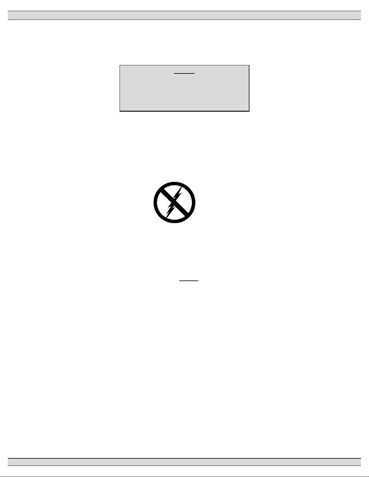
NOTE:
CAUTION
contents subject to damage by
STATIC ELECTRICITY
This equipment contains static-sensitive parts. Please observe the following anti-static
precautions at all times when handling this equipment. Failure to observe these
precautions may cause equipment failure and/or damage.
• Discharge body static charge before handling the equipment (contact a grounded
surface and maintain contact while handling the equipment, a grounded wrist strap
can/should also be utilized).
• Do not touch any components on the printed circuit board with your hands or any
other conductive equipment.
• Do not place the equipment on or near materials such as Styrofoam, plastic and
vinyl. Place the equipment on grounded surfaces and only use an anti-static bag
for transporting the equipment.
1.3. NOTES TO TRANSFER SWITCH INSTALLER
1.3.1. SYSTEM VOLTAGE
If the transfer switch has programmable/multi-tap system voltage capability (refer to
electrical schematic), confirm the transfer switch has been configured for the correct
PM091 Rev 1 09/02/27 Thomson Technology
2
Page 7
TSC 80e TRANSFER SWITCH CONTROLLER
system voltage. If the transfer switch requires reconfiguring, the TSC80e controller will
require re-programming as well.
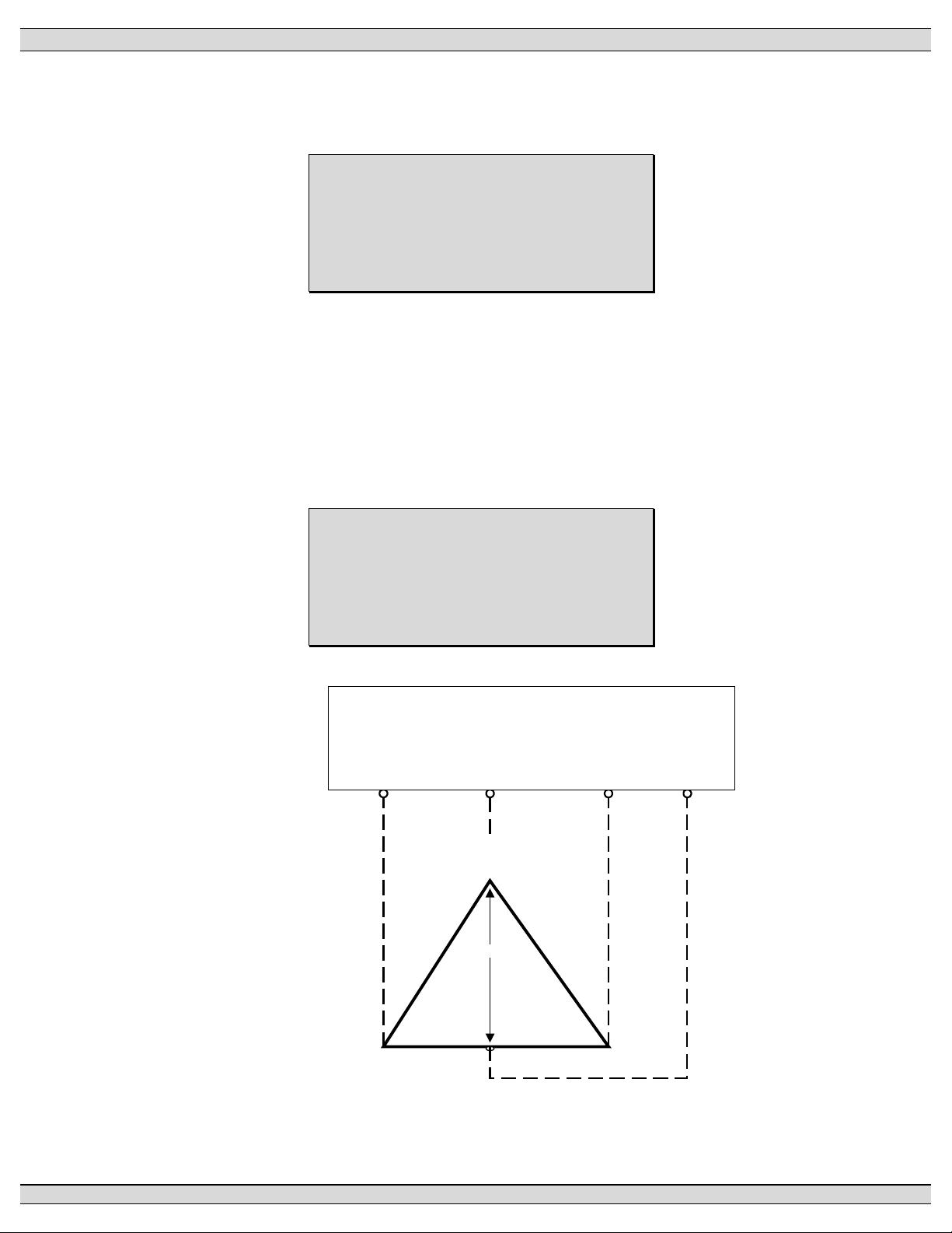
WARNING
Failure to confirm and match transfer
switch voltage with the system voltage
could cause serious equipment damage.
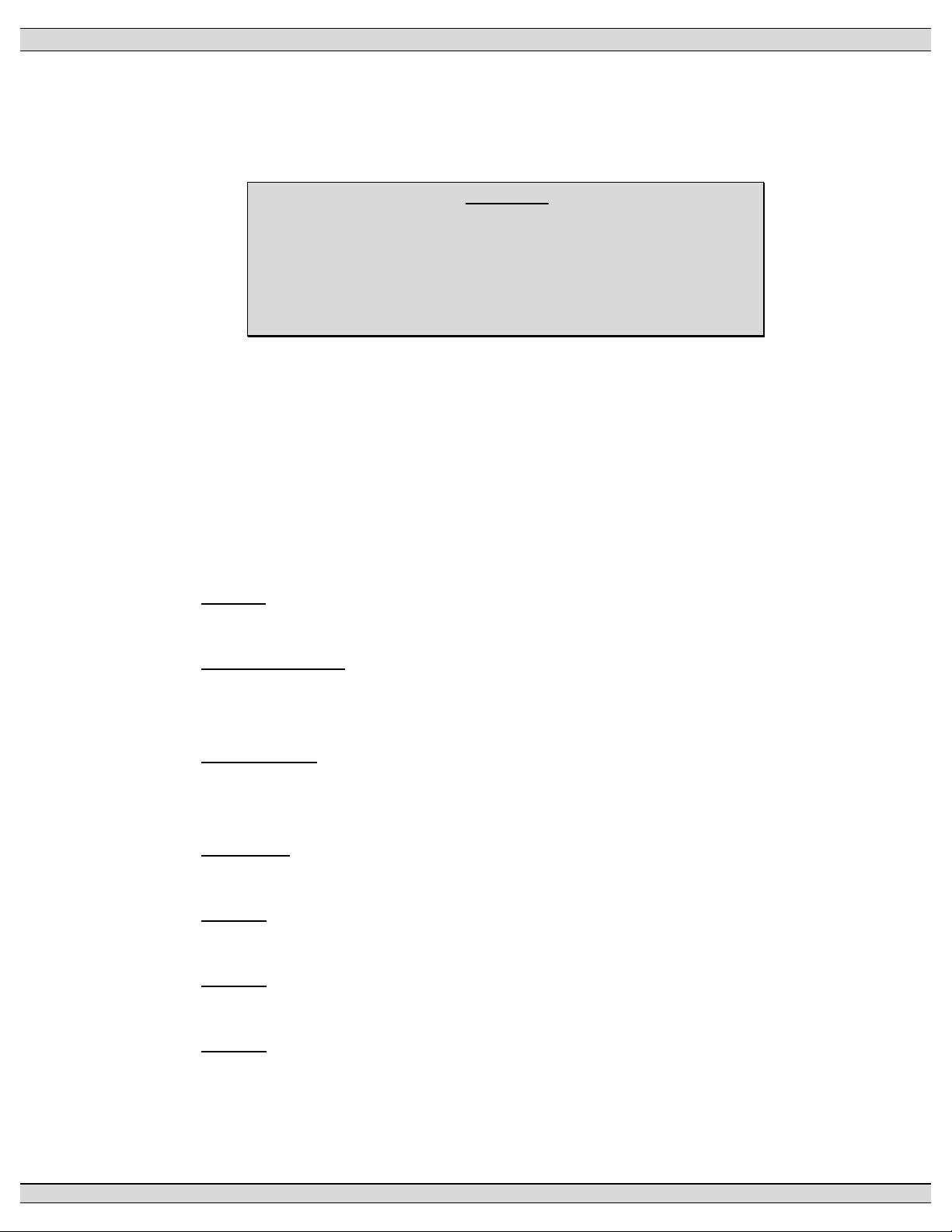
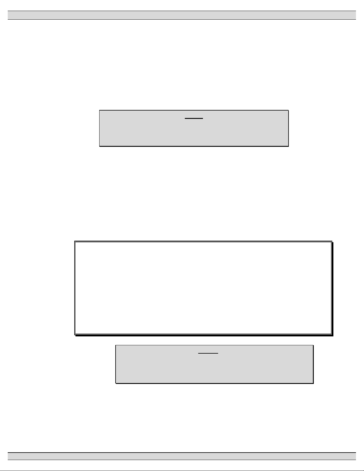
1.3.2. SYSTEM PHASING - HIGH LEG DELTA SYSTEMS
When the transfer switch is connected to a 3-phase 4-wire delta systems, the “High”
leg (Phase B, colored Orange), must be connected to Phase B of the Utility and/or
Generator supply. This will ensure the ATS control power, which is internally
connected between Phase A and Neutral is maintained at 120VAC. Refer to figure
below for further details.
WARNING
Failure to match correct system phasing
will result in serious damage to the
TSC 80e controller.
Auto m atic Transfer
Switch (U tility Supply)
PH A
(U A)
240V 240V
PH B
(U B)
B
(Or ange )
(Hi gh L eg )
20 8V
PH C
(U C )
Ne u ra l
(N )
A
(R ed)
12 0V 120V
C
(Ye llow)
N
(W hite )
PM091 Rev 1 09/02/27 Thomson Technology
3
Page 8

TSC 80e TRANSFER SWITCH CONTROLLER
CAUTION!!!
All installation and/or service work performed must be done by qualified
personnel only. Failure to do so may cause personal injury or death.
1.3.3. REMOTE START CONTACT FIELD WIRING
As a minimum, the remote engine start control field wiring shall conform to the local
regulatory authority on electrical installations. Field wiring of a remote start contact
from a transfer switch to a control panel should conform to the following guidelines to
avoid possible controller malfunction and/or damage.
1.3.3.1.Minimum #14 AWG (2.5mm2) wire size shall be used for distances up to
100ft (30m)1). For distances exceeding 100 ft. (30m) consult Thomson
Technology.
1.3.3.2.Remote start contact wires should be run in a separate conduit.
1.3.3.3.Avoid wiring near AC power cables to prevent pick-up of induced
voltages.
1.3.3.4.An interposing relay may be required if field-wiring distance is
excessively long (i.e. greater than 100 feet (30m)) and/or if a remote
contact has a resistance of greater than 5.0 ohms.
1.3.3.5.The remote start contact provided is voltage free (i.e. dry contact).
Refer to the “TSC 80e Typical Connection Diagram” on page 52 for
terminal interface and contact voltage/current ratings or page 13 for
specifications on output contact ratings. Applying voltage or current in
excess of the ratings will damage the controller and is not cover by
Thomson Technology’s limited warranty.
1.3.4. DIELECTRIC TESTING
Do not perform any high voltage dielectric testing on the transfer switch with the
TSC80e controller connected into the circuit, as serious damage will occur to the
controller. All AC control fuses and control circuit isolation plugs connected to the
TSC80e must be removed if high voltage dielectric testing is performed on the transfer
switch.
PM091 Rev 1 09/02/27 Thomson Technology
4
Page 9

TSC 80e TRANSFER SWITCH CONTROLLER
2. DESCRIPTION
The TSC 80e controller utilizes microprocessor-based design technology, which provides high
accuracy for all voltage sensing and timing functions. The TSC 80e is factory configured to control all
the operational functions and display features of the automatic transfer switch.
The TSC 80e controller consists of two parts; a Lexan faceplate, which is mounted externally on the
transfer switch door, and a printed circuit board (PCB), which is mounted inside the transfer switch on
the enclosure door. The TSC 80e PCB contains a built-in LCD display that is visible from the front
panel faceplate. The Lexan faceplate contains operation/data-acquisition/programming pushbuttons
and indication LEDs.
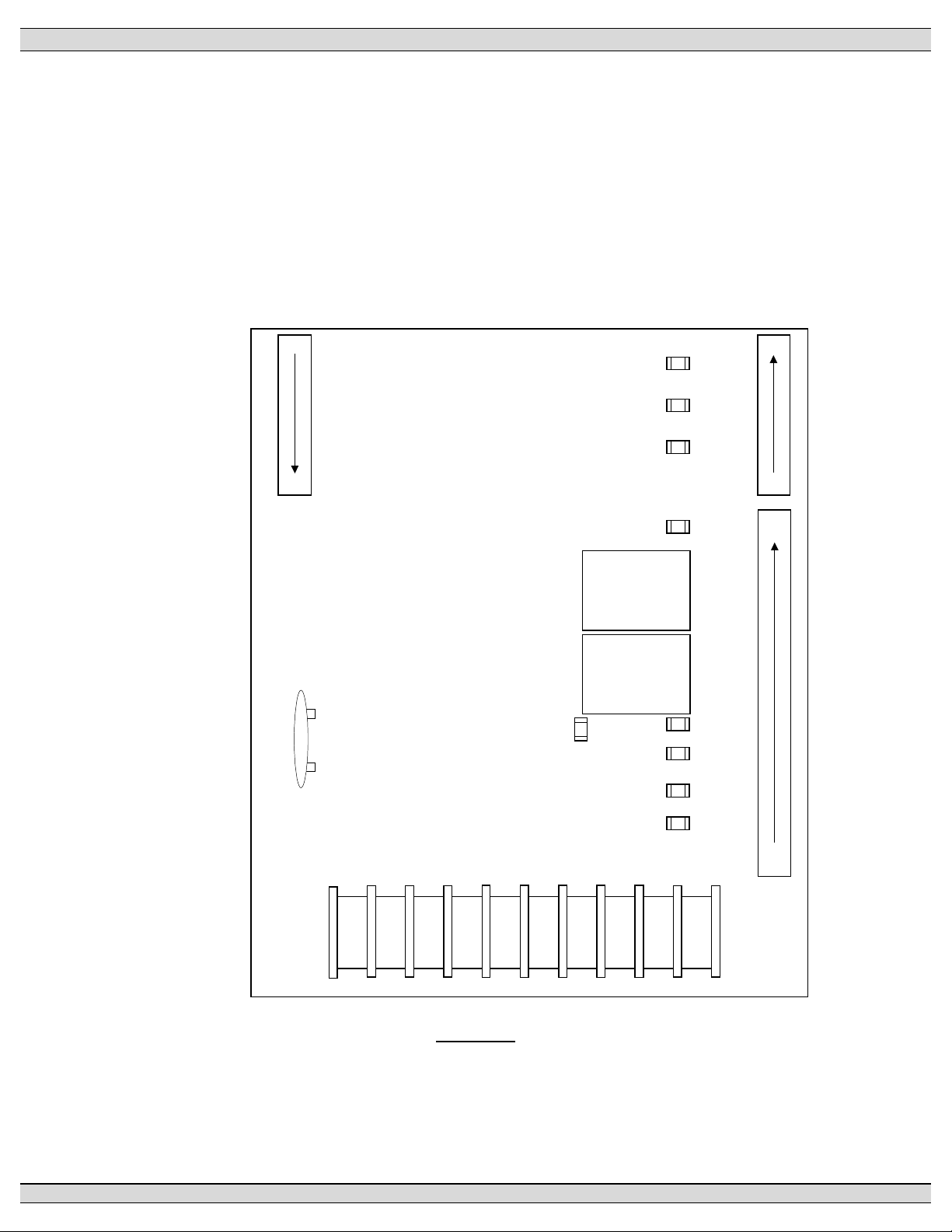
2.1. LEXAN FACEPLATE
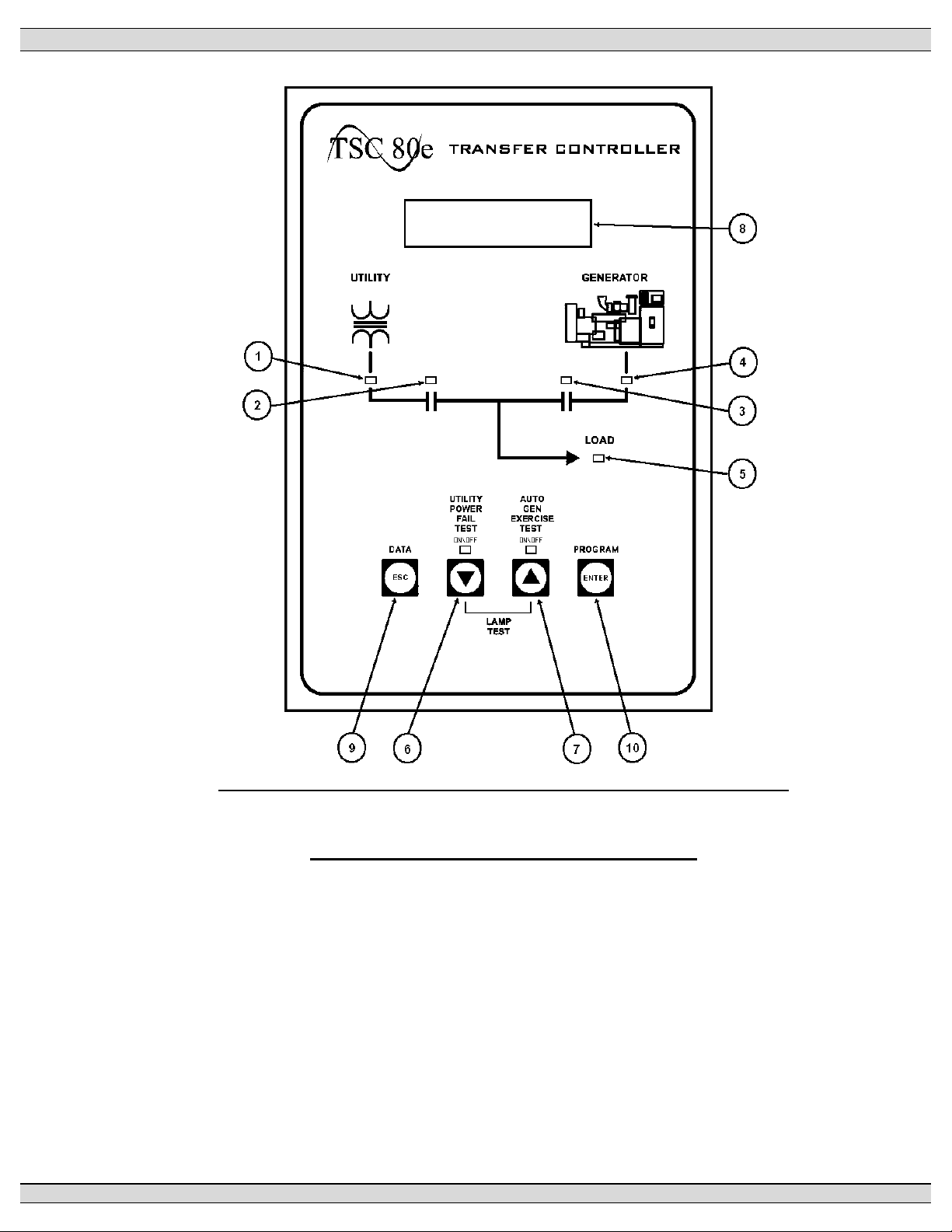
The TSC 80e Controller Lexan faceplate is shown as in FIGURE 1. The Lexan pushbuttons
and LED lights are connected to the main PCB via plug-in ribbon cable. The main features of
the Lexan faceplate are described as follows with reference to FIGURE 1.
Utility Supply Available LED light
Load on Utility supply LED light
Load on Generator supply LED light
Generator Supply Available LED light
ATS Load Bus Energized LED light
Utility Power Fail Test Mode Pushbutton (Program value DECREMENT/DOWN Pushbutton) & LED light
Auto Generator Exercise Mode Pushbutton (Program value INCREMENT/UP Pushbutton) & LED light
LCD Display Screen Viewing Window
Programming Escape/Data Log review Pushbutton
Programming Enter Pushbutton
PM091 Rev 1 09/02/27 Thomson Technology
5
Page 10
TSC 80e TRANSFER SWITCH CONTROLLER
FIGURE 1 - TSC 80e Controller Lexan Faceplate
• ESC pushbutton. The ESC function is used to “ESCAPE” or exit the last field or
programming menu. The program menu is a drill down format; by pressing the
ESC button the program steps back one layer at a time until it escapes/exits
the program menu. The ESC function can also be used to view the controllers
Data Logs that are stored.
• DOWN pushbutton. The DOWN function is used to change or decrement
values while in the programming mode and is used to scroll down through the
status menus or programming sub menus to the next item.
PM091 Rev 1 09/02/27 Thomson Technology
6
Page 11
TSC 80e TRANSFER SWITCH CONTROLLER
• UP pushbutton. The UP function is used to change or increment a
programming value while in the programming mode and is used to scroll up
through the status menus or programming sub menus to the previous item.
• ENTER pushbutton. The ENTER function is used to access the Program
menus and “enters” and accept new programming or operating mode changes
after a new value has been selected.
2.2. PRINTED CIRCUIT BOARD
38
44
TB7
BT1
REAL TIME
CLOCK
BATTERY
SYS OK
PROG 2
PROG 3
PROG 1
ENG STOP
TRANSFORMER
TRANSFORMER
XFER UTIL
XFER GEN
LD ON GEN
(PROG 4)
LD ON UTIL
(PROG 5)
TB6
37
29
28
11
1
TB2-5
1
10
9
8
7
6
5
4
3
2
TB1
FIGURE 2
The printed circuit board (PCB) is shown in FIGURE 2. The PCB contains the following user
interface items:
PM091 Rev 1 09/02/27 Thomson Technology
7
Page 12
TSC 80e TRANSFER SWITCH CONTROLLER
2.2.1. TERMINAL BLOCKS
Terminal blocks are located on the PCB as follows:
TB1 High voltage sensing terminal block (120-600VAC).
WARNING
Voltage sensing circuits are capable of lethal voltages while
energized. Standard safety procedures should be followed and
be performed by qualified personnel only. Failure to do so may
cause personnel injury and/or death.
TB2-TB6 Transfer control terminal block for 120VAC control power and input/output
circuits.
TB7 Low voltage control inputs (5VDC internally powered, switched to terminal
38).
2.2.2. DIAGNOSTIC LED’S
The TSC 80e controller provides diagnostic LED lights, which are mounted on the
printed circuit board as per FIGURE 2. Their functions are described as follows:
SYS OK LED flashes on and off at irregular intervals, which indicates
the microprocessor is functioning normally.
XFER TO UTILITY LED illuminates whenever the TSC 80e is initiating a signal
to transfer to the Utility supply. (UP transfer contact as noted
on the electrical schematic is closed)
XFER TO GEN LED illuminates whenever the TSC 80e is initiating a signal
to transfer to the Generator supply. (GP transfer contact as
noted on the electrical schematic is closed)
ENG STOP LED illuminates whenever the TSC 80e is initiating an
ENGINE STOP (remote start contact is open).
PROG 1 LED illuminates whenever the Programmable output Relay
#1 is turned on (relay on the circuit board is energized).
PROG 2 LED illuminates whenever the Programmable output Relay
#2 is turned on (relay on the circuit board is energized).
PROG 3 LED illuminates whenever the Programmable output Relay
#3 is turned on (relay on the circuit board is energized).
PM091 Rev 1 09/02/27 Thomson Technology
8
Page 13

TSC 80e TRANSFER SWITCH CONTROLLER
LD ON GEN (PROG 4) LED illuminates whenever the Programmable output Relay
#4 is turned on (relay on the circuit board is energized).
Factory default function is “Load on Gen”.
LD ON UTIL (PROG 5) LED illuminates whenever the Programmable output Relay
#5 is turned on (relay on the circuit board is energized).
Factory default function is “Load on Utility”.
2.3. TSC 80e CONTROLLER FEATURES
The Thomson Technology TSC 80e Transfer Switch Controller utilizes the latest
advancements in microprocessor technology, printed circuit board assembly and software for
control of automatic transfer switches. The TSC 80e is the second generation of
microprocessor-based transfer switch controllers from Thomson Technology, and reflects over
30 years of transfer switch control experience. The TSC 80e is factory configured to monitor,
display and control all operational functions of the automatic transfer switch. All voltage
sensors and timers are fully user adjustable utilizing software configuration. The
microprocessor design provides high accuracy for all voltage sensing and timing functions as
well as providing many standard features.
• Utility AC voltage sensing (true RMS) – 120-600V single phase or 3 phase
• Generator AC voltage sensing (true RMS) – 120-600V single phase or 3 phase
• Generator AC frequency sensing
• Utility under voltage control setpoint 70 - 95% (adjustable)
• Generator under voltage control setpoint 70 - 95% (adjustable)
• Generator under frequency control setpoint 70 - 90% (adjustable)
• Engine warm-up timer 0-60 sec. (adjustable)
• Utility return timer 0-30 min. (adjustable)
• Engine start timer 0-60 sec. (adjustable)
• Engine cooldown timer 0-30 min. (adjustable)
• Neutral position delay timer 0-60 sec. (adjustable)
• Local utility power fail simulation test pushbutton & LED, door mounted
• Remote utility power fail simulation test pushbutton input (via terminal block)
• Load on utility supply & load on generator supply LED’s, door mounted
• Utility and generator source available LED’s, door mounted
• Weekly plant exercise timer (30 min. on load) manually initiated
PM091 Rev 1 09/02/27 Thomson Technology
9
Page 14

TSC 80e TRANSFER SWITCH CONTROLLER
• Local plant exercise initiate pushbutton & LED, door mounted
• Engine start contact (10A, 120/240VAC resistive max.)
• Transfer fail/forced transfer logic
• Automatic force transfer to alternate supply should load voltage become de-
energized
• 50 or 60Hz capable (120V control power)
• Remote Load Test/Peak Shave Input
• LCD Display: Built-in, front faceplate mounted LCD Display for monitoring 3
phase Utility/Generator voltage, system frequency and timer countdown
operation
• Front Panel Programming: All controller set points can be programmed using
built-in faceplate mounted pushbuttons & LCD display with password security
• Load Disconnect Contact (LDC): Integrated Load Disconnect Contact (LDC)
feature provides pre/post transfer control to signal external building systems
such as elevators during transfer operations
• Generator Exercise Timer (EXT): Integrated Generator Exercise Timer (EXT)
with easy to use 4 event, 7-14-21-28 Day, On-load or Off-load Programmability
• Real-time Clock: On Board Real-time clock c/w battery back-up & daylight-
savings programming functionality
• Event Data Logging: Data logging of key events including total transfers to
generator, total utility power failures, load on utility hours, load on generator
hours and utility or generator voltage/ frequency data at time of fault
• 5 Programmable Output Contacts: Additional Programmable Output Contact
rated 10A, 120/240V resistive, Form C with the following available functions:
Fail to Transfer, Load on Utility, Load on Gen, Utility Power Available (UPA),
Generator Power Available (GPA), ATS Not in Auto, ATS in Auto, Transfer to
Gen, Transfer to utility, Switch failure, and limit switch failure.
PM091 Rev 1 09/02/27 Thomson Technology
10
Page 15

TSC 80e TRANSFER SWITCH CONTROLLER
2.4. APPLICATION INFORMATION
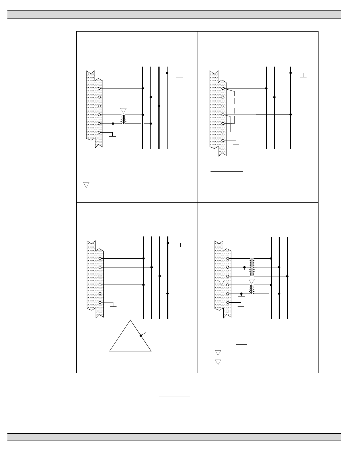
2.4.1. AC VOLTAGE SENSING INPUT
The TSC 80e can accept direct AC voltage sensing inputs on the generator and utility
supplies from 120-600VAC (nominal). Note: Direct input voltage sensing can only be
used when the system utilizes a 3 phase, 4 wire distribution system which has the
neutral conductor solidly grounded. For 3 phase, 3 wire systems (i.e. no neutral) or
high voltage systems, potential transformers must be used. Refer to FIGURE 3 for
voltage sensing connections.
PM091 Rev 1 09/02/27 Thomson Technology
11
Page 16
TSC 80e TRANSFER SWITCH CONTROLLER
3Ø, 4W 208/380/480/600VAC DIRECT SENSING
TSC 80e
1
2
3
25
26
24
VOLTAGE INPUTS
600VAC L-L, 347VAC L-N
480VAC L-L, 277VAC L-N
380VAC L-L, 220VAC L-N
208VAC L-L, 120VAC L-N
PT REQUIRED FOR TRANSFER SWITCH MECHANISM POWER
1
(MUST BE SIZED TO SUIT POWER REQUIREMENTS).
NOTE: UTILITY VOLTAGE SENSING AND
CONTROL POWER SHOWN ONLY.
1
120
GRD
GRD
BA C N
GRD
SINGLE PHASE, 3W 120/240VAC DIRECT SENSING
TSC 80e
1
2
3
NO CONNECTION
10
25
26
24
GRD
VOLTAGE INPUTS
240VAC L-L, 120VAC L-N
NOTE: UTILITY VOLTAGE SENSING SHOWN ONLY.
L2L1 N
GRD
3Ø, 4W 120/240V HIGH LEG DELTA DIRECT CONNECTION
TSC 80e
1
2
3
25
26
24
120V
GRD
BA C N
GRD
A
N
B C
NOTE: FOR HIGH LEG DELTA SYSTEMS PHASING OF CUSTOMER SUPPLY MUST
BE CONNECTED AS SHOWN ABOVE. FAILURE TO COMPLY WILL RESULT IN DAMAGE
TO CONTROLLER.
NOTE: UTILITY VOLTAGE SENSING AND CONTROL POWER SHOW N ONLY.
3Ø, 3W DELTA PT's
TSC 80e
1
120
2
GRD
120
3
25
2
26
24
PT REQUIRED FOR TRANSFER SWITCH MECHANISM POWER
1
(MUST BE SIZED TO SUIT POWER REQUIREMENTS).
TSC80e CONTROLLER MUST BE PROGRAMMED FOR CORRECT
2
PT RATIO AND SECONDARY PT VOLTAGE IN SOFTWARE
NOTE: UTILITY VOLTAGE SENSING SHOWN ONLY.
1
120
GRD
GRD
SECONDARY PT VOLTAGE
120VAC L-L [NO NEUTRAL]
NOTE: ØB IS GROUNDED
BA C
FIGURE 3
PM091 Rev 1 09/02/27 Thomson Technology
12
Page 17

TSC 80e TRANSFER SWITCH CONTROLLER
2.4.2. AC CONTROL POWER INPUT
The TSC 80e is factory supplied for 120VAC (nominal) control power input voltage.
Independent AC control power is required from both utility and generator supplies. AC
control power is utilized for internal TSC 80e control circuits and external control
device loads. The TSC 80e requires approximately 6 VA power for internal control
circuits. The maximum external load is limited by output contact ratings (i.e. 10A
resistive, 120VAC). Total AC control power requirements for each supply must be
determined by adding both internal and external load requirements.
2.4.3. OUTPUTS
The TSC 80e provides the following types of output circuits:
Engine Start Contact Isolated Form B contact (10A, 120VAC Resistive)
Transfer to Utility Output 120VAC, 10A (Resistive) powered output contact
Transfer to Generator Output 120VAC, 10A (Resistive) powered output contact
The TSC 80e provides the following additional output circuits:
Programmable Output
Contact #1
Programmable Output
Contact #2
Programmable Output
Contact #3
Programmable Output
Contact #4
Programmable Output
Contact #5
Isolated Form C contact (10A, 120VAC/250VAC
Resistive)
Isolated Form C contact (10A, 120VAC/250VAC
Resistive)
Isolated Form C contact (10A, 120VAC/250VAC
Resistive)
Isolated Form C contact (10A, 120VAC/250VAC
Resistive)
Isolated Form C contact (10A, 120VAC/250VAC
Resistive)
Interposing relays are required between the TSC 80e outputs and the end device if
loads exceed the output current rating.
PM091 Rev 1 09/02/27 Thomson Technology
13
Page 18

TSC 80e TRANSFER SWITCH CONTROLLER
3. OPERATING INSTRUCTIONS
To operate the TSC 80e controller and associated transfer switch using the front faceplate
pushbuttons, refer to the following detailed operating instruction sub-section descriptions.
3.1. AUTOMATIC SEQUENCE OF OPERATION
3.1.1. NORMAL OPERATION
Under normal operating conditions, the transfer switch operates automatically during a
failure and restoration of utility power and does not require operator intervention.
When utility supply voltage drops below a preset nominal value (70 - 95% of rated
adjustable) on any one phase, an engine start delay will be initiated and the transfer to
utility supply signal will be removed (i.e. contact opening). Following expiry of the
engine start delay period (0 - 60 sec. adjustable) an engine start signal will be given
(contact closure, relay drops out to initiate start sequence).
Once the engine starts, the transfer switch controller will monitor the generators
voltage and frequency levels. When the generator voltage and frequency rises above
preset values (70 - 95% nominal adjustable) the Engine Warm-up timer will be
initiated. After the Engine Warm-up timer expires (0-60 sec. Adjustable), the transfer to
generator supply signal (contact closure) will be given to the transfer switch
mechanism. The load will then transfer from the utility supply to the generator supply
via motor driven mechanism (Neutral Delay is bypassed on utility failure detection).
The generator will continue to supply the load until the utility supply has returned and
the retransfer sequence is completed as follows: When the utility supply voltage is
restored to above the present values (70 - 95% of rated adjustable) on all phases, a
transfer return delay circuit will be initiated. Following expiry of the utility transfer
return timer (0 - 30 min. adjustable), the transfer to generator supply signal will be
removed (contact opening), then the transfer to utility supply signal (contact closure)
will be given to the transfer switch mechanism. The load will then be transferred from
the generator supply back to the utility supply. During the utility re-transfer sequence a
neutral positioning delay circuit will cause the transfer mechanism to pause in the
“neutral position (i.e. with both transfer power switching devices open) for the duration
of the neutral delay timer (0-30 seconds adjustable) setting. Once the neutral delay
expires, the re-transfer sequence will be completed.
PM091 Rev 1 09/02/27 Thomson Technology
14
Page 19
TSC 80e TRANSFER SWITCH CONTROLLER
An engine cooldown timer circuit will be initiated once the load is transferred from the
generator supply. Following expiry of the cooldown delay period (0 - 30 min.
adjustable) the engine start signal will be removed (contact opening) to initiate
stopping of the generator set.
3.1.2. ABNORMAL OPERATION
3.1.2.1.TEST CONDITION
A test pushbutton on the transfer switch shall signal a simulated utility power
fail signal to the transfer switch controller. The transfer switch shall operate as
per a normal utility power fail condition. The neutral delay circuit logic will be
active during transfer to and from the generator supply (i.e. when both sources
of power are available).
The transfer switch shall remain on generator supply until the test mode is
terminated. It will then retransfer back to the utility supply following expiry of
the transfer return timer and then continue to operate the generator set for its
cooldown period then stop.
3.1.2.2.GENERATOR FAILURE ON LOAD
Should the generator set fail while on load, the transfer switch shall retransfer
the load back to the utility supply if within nominal limits. The utility return and
neutral delay timers will be bypassed in this condition.
NOTE
This operating condition shall apply to a normal utility failure as
well as any test condition.
3.1.2.3.TRANSFER SWITCH FAIL ALARM LOGIC
The TSC 80e controller contains logic to detect a transfer mechanism failure.
Should a failure be detected, a forced transfer to the alternate supply will be
initiated. Detailed logic operation is as follows:
NOTE
Disabling of the “TRANSFER SWITCH FAIL” feature is possible
by selecting the “Disconnected” position on “Service Entrance
Models” or by a closure between terminals 38 & 42 on the TSC
80e. In these situations the TSC 80e controller will not verify
that the transfer mechanism has operated correctly to provide
power to the load bus.
PM091 Rev 1 09/02/27 Thomson Technology
15
Page 20

TSC 80e TRANSFER SWITCH CONTROLLER
3.1.2.4.TRANSFER FAIL DETECTION-NORMAL STEADY STATE
CONDITION (NON-TRANSFERRING)
i. Limit Switch Failure (i.e. open contact) - Transfer Fail Alarm is initiated
(Load on Source Flashing LED) after a 9-second delay, and then a forced
transfer to the alternate source is initiated, if valid and available. Re-
transfer back to the original source will not occur until the Transfer Fail
alarm condition is reset. Refer to item 3.3 for Transfer Fail Fault Reset
details.
ii. Loss of Load Voltage (<80VAC) (i.e. Power switching device Tripped or
Failed to Close/Conduct Condition) - Transfer Fail Alarm is initiated (Load
Source Flashing LED) after a 5-second delay, then a forced transfer to the
alternate source is initiated, if valid and available. Re-transfer back to the
original source will not occur until the Transfer Fail alarm condition is reset.
Refer to item 3.3 for Transfer Fail Fault Reset details.
iii. Limit Switch Failure & Loss of Load Voltage <80VAC - Transfer Fail Alarm
is initiated (Load Source Flashing LED) after an 11-second delay, then a
forced transfer to the alternate source is initiated, if valid and available. Re-
transfer back to the original source will not occur until the Transfer Fail
alarm condition is reset. Refer to item 3.3 for Transfer Fail Fault Reset
details.
3.1.2.5.TRANSFER FAIL DETECTION - TRANSFERRING CONDITION
Transfer Source to Neutral – “NEUTRAL POSITION TIME” (10 seconds-
adjustable) starts timing as soon as a transfer to the alternate source is
initiated. During this period the ATS motor is energized and moves the
mechanism from the original source to neutral. The power to the motor will be
de-energized when either the “NEUTRAL POSITION TIME” times out or the
load voltage drops below 80VAC on all phases (whichever occurs first). Once
the ATS motor is de-energized, the Neutral Delay timer starts timing (all other
timers are halted while neutral delay timer is running). Once the Neutral Delay
timer expires the motor is re-energized to continue the transfer (see below).
Note: Normally the load voltage will typically drop below the 80VAC setpoint
within 1 second when the source power-switching device opens and therefore
the “NEUTRAL POSITION TIME” never times out. The default setting of this
timer (10 seconds) is intentionally set long so that it will not pre-maturely stop
the ATS mechanism.
PM091 Rev 1 09/02/27 Thomson Technology
16
Page 21

TSC 80e TRANSFER SWITCH CONTROLLER
Transfer Neutral to Source– “Find Neutral/Source Timer” starts timing as soon
as the Neutral Delay timer times out. During this period the motor is energized
and moves the mechanism from the neutral to the alternate source. The power
to the ATS motor will be de-energized when either the mechanism’s limit switch
activates (i.e. external logic to the TSC 80e) or the “Find Neutral/Source Timer”
times out (whichever occurs first). Note: During the above 2 sequences the
“Transfer Fail Alarm” logic is inhibited. Once the 2 sequences have been
completed, the “Transfer Fail Alarm” logic will be re-enabled and will only be
triggered if conditions as described in item A (Normal Steady State Condition)
are sensed (limit switch and/or loss of load voltage).
For example, if the ATS mechanism fails to move (i.e. due to broken rod, motor
failure or manual release plunger not re-engaged), the total time before a
transfer fail will be initiated is 31 seconds (i.e. Find Neutral/Source Timer” (10
sec) + Find Neutral/Source Timer” (10 sec) + Limit Switch Failure & Loss of
Load Voltage <80VAC (11 sec) = 31 seconds Total).
3.1.2.6.SERVICE ENTRANCE ATS
For Service Entrance Rated transfer switch applications, the transfer switch
control logic will include external wiring from the TSC 80e to signal the transfer
switch mechanism to move to the “Service Disconnected” position. In this mode
the TSC 80e transfer control outputs and Transfer Fail feature is disabled.
3.2. TEST MODES
3.2.1. UTILITY POWER FAIL SIMULATION (LOAD TEST)
To simulate a utility power failure condition, press and hold the “UTILITY
POWER FAIL SIMULATE” pushbutton on the Lexan faceplate until the LED
light above the pushbutton changes state, approximately 5 seconds. Once the
mode is initiated, the engine start will be activated, when the engine
accelerates to nominal voltage and frequency levels, the load will automatically
transfer to the generator supply. To terminate the Utility Power Fail Test Mode,
the Test pushbutton must be held until the LED light above the pushbutton
changes state, approximately 5 seconds. When the pushbutton is released the
LED light will go out and, the load will re-transfer back to the utility supply
following expiry of the Utility Return delay timer.
PM091 Rev 1 09/02/27 Thomson Technology
17
Page 22

TSC 80e TRANSFER SWITCH CONTROLLER
NOTE
The load will automatically re-transfer to the utility supply should
the generator fail while on load and the utility supply is within
applicable limits.
3.2.2. AUTOMATIC PLANT EXERCISE TEST
The TSC 80e controller provides both pre-programmed and user
programmable automatic plant exercise programs. Refer to SECTION 4.6.3 for
further details on the programmable “Automatic Exercise”. The generator set
will be exercised either “on or off” load dependent upon the controller software
program setting (refer to SECTION 4.6.5.11).
To initiate an automatic plant exercise mode cycle, press and hold the AUTO
GEN EXERCISE TEST pushbutton on the Lexan faceplate until the LED light
above the pushbutton changes state, approximately 5 seconds. Once the
mode is initiated, the engine will immediately start and transfer on load (i.e. if
configured for On Load Test, “factory default is off load test”) once nominal
voltage and frequency levels have been obtained. The engine will remain
operating on load until the plant exercise time delay period of 30 minutes
expires, then the load will re-transfer back to the utility supply. The system will
then be automatically re-tested at the programmed “Automatic Exercise”
Start/Stop/Day/Time.
NOTES
1. The load will automatically re-transfer to the utility supply
should the generator fail while in the test mode.
2. To bypass the exercise run period, press and hold the
Exercise pushbutton on for 5 seconds until the LED remains on.
The Generator Exercise LED light will operate as follows:
LED ON - Exercise Timer is initiated, the programmable 7-14-21-28 day
timer is active and the generator is in the off state.
LED FLASHING - Exercise Timer is initiated, the programmable minute
run timer is active and the generator is running on loads.
LED OFF - Exercise Timer is not initiated and the programmable timer
is not active.
To terminate the Auto Generator Exercise Mode, the Exercise pushbutton must
be held on for approximately 5 seconds until the LED light above the
PM091 Rev 1 09/02/27 Thomson Technology
18
Page 23

TSC 80e TRANSFER SWITCH CONTROLLER
pushbutton starts flashing. When the pushbutton is released, the LED light will
go out and the system will return to normal operation.
NOTE
To enable the Auto Exercise mode without initiating an
immediate exercise test, operator must first place the gen set
engine control to off, then press the Exercise button once to
initiate the test feature, then press it a second time to cancel
the immediate test. The gen set engine control can then be
returned back to the Automatic position, no starting of the gen
set or transferring of the facility loads should occur.
3.2.3. FOUR FUNCTION REMOTE TEST (FTS4 OPTION)
The function of the Four Position Test Switch Input is to allow operators to select various
operating scenarios for test or maintenance purposes, in addition to the use of the faceplate
mounted pushbuttons.
NOTE: When an external FTS4 switch is used, the TSC 80e operation as selected from the
faceplate pushbuttons will be overridden.
OFF: Disables the engine start output from the transfer switch. If the
primary source is available, and within normal limits, the TSC 80e
will initiate a transfer to the primary source. The transfer switch will
not automatically transfer to the secondary (alternate) source should
the primary source fail.
AUTO: All automatic functions are enabled.
ENGINE START: (No load test) An engine start signal will be initiated and will remain
on until the FTS4 is placed in another position. The engine will start
if the engine’s auto start controller is in the ”Auto” mode. If the
primary source fails in this mode, and the secondary source is within
parameters, the TSC 80e will initiate a transfer to the secondary
source. When the Engine Start input is removed, the generator will
continue to run if it has not operated for a time equal to or greater
than the minimum run time (i.e. based on the Engine Cooldown
Timer setting).
PM091 Rev 1 09/02/27 Thomson Technology
19
Page 24

TSC 80e TRANSFER SWITCH CONTROLLER
TEST: (Full load test) A primary source failure is simulated and an engine
3.2.4. REMOTE TEST
To activate a remote load test, a remotely controlled contact is to be closed between
terminal #38 and terminal #44. When the contact closes, an engine start will be
activated, once the engine accelerates to nominal voltage & frequency levels and the
Warm Up Timer expires, the load will be automatically transfer to the generator supply.
When the remote contact is opened, the load will re-transfer back to the utility supply
start signal will be initiated. When the secondary source is within
normal limits, the TSC 80e will initiate a transfer to the secondary
source. The system will remain in this state until the FTS4 is placed
in another position or the secondary supply fails. Upon a secondary
supply failure, if the primary supply is available, the TSC 80e will
initiate a transfer to the primary supply. The Engine Cooldown time
sequence will be initiated when the test mode is terminated.
following expiry of the Utility Return delay timer. The Engine Cooldown time sequence
will be initiated when the test mode is terminated.
The load will automatically re-transfer to the utility supply should
the generator fail while on load.
3.3. TRANSFER FAIL FAULT RESET
To reset a Transfer Fail condition, simultaneously press and hold both the Up & Down
arrow pushbuttons on the Lexan faceplate for approximately 5 seconds, the LEDs
above the buttons will commence oscillating after 5 seconds indicating the reset has
been achieved. A flashing LED above the associate source contact on the face of the
TSC 80e Lexan annunciates a Transfer Fail alarm condition. This event will cause the
TSC 80e to force a transfer of the facility loads to the alternate source, after the fault is
reset; the load will automatically retransfer back to the preferred/selected source if
within normal limits (a slight delay is typical before re-transfer commences).
NOTE
PM091 Rev 1 09/02/27 Thomson Technology
20
Page 25

TSC 80e TRANSFER SWITCH CONTROLLER
3.4. LAMP TEST
To initiate a Lamp Test, simultaneously press both the Up & Down arrow pushbuttons
on TSC 80e Lexan faceplate. The Lexan LEDs will flash confirming their operation.
The Lamp Test Function will also clear a Transfer Failure or
allow select active timers to be bypassed if held longer than 5
seconds.
3.5. TIMER BYPASS
To bypass an active timing sequence (e.g. utility return timer, cooldown timer, warm-up
timer, cooldown timer), simultaneously press both the Up & Down arrow pushbuttons
on Lexan faceplate (i.e. UTILITY POWER FAIL SIMULATE & GENERATOR
EXERCISE MODE) for approximately 5 seconds, the LEDs above the buttons will
NOTE
commence oscillating after 5 seconds indicating the bypass has been achieved.
PM091 Rev 1 09/02/27 Thomson Technology
21
Page 26

TSC 80e TRANSFER SWITCH CONTROLLER
3.6. TSC 80e LCD DISPLAY OPERATION
The TSC 80e incorporates a Liquid Crystal Display (LCD) that is visible on the front faceplate.
The LCD has pre-programmed displayed messages which are automatically displayed in an
auto-Scrolling mode or they may be selected manually by pressing the UP or DOWN
pushbuttons in succession until the desired menu is displayed. The display menu types and
order in which they are programmed are as follows:
3.6.1. LCD DISPLAY SCREENS
The following seventeen (17) Display Screens are provided:
SOFTWARE VERSION
SYSTEM TIME CLOCK
GENERATOR VOLTAGE/FREQUENCY
UTILITY VOLTAGE/FREQUENCY
SYSTEM CONFIGURATION
GENERATOR UNDER VOLTAGE SETPOINT
GENERATOR UNDER FREQ. SETPOINT
GEN SET START DELAY COUNTER/SETPOINT
GEN SET WARMUP DELAY COUNTER/SETPOINT
GEN SET COOLDOWN DELAY COUNTER/SETPOINT
NEUTRAL DELAY COUNTER/SETPOINT
UTILITY UNDER VOLTAGE SETTING
UTILITY RETURN COUNTER/SETPOINT
AUTO EXERCISE MODE STATUS
GENERATOR MODE STATUS
UTILITY FAULT STATUS
GENERATOR FAULT STATUS
PM091 Rev 1 09/02/27 Thomson Technology
22
Page 27

TSC 80e TRANSFER SWITCH CONTROLLER
3.6.1.1.SOFTWARE VERSION
The LCD screen displays the current version number of TSC 80e software
installed in the controller.
3.6.1.2.SYSTEM TIME CLOCK
The LCD screen displays the current date and time, based on what has been
programmed to the TSC 80e controller.
3.6.1.3.GENERATOR VOLTAGE/FREQUENCY
The LCD screen displays the current generator voltage (3 phase or single
phase, line– to – line or line to neutral voltages) and frequency.
3.6.1.4.UTILITY VOLTAGE/FREQUENCY
The LCD screen displays the current utility voltage (3 phase or single phase,
line– to – line or line to neutral voltages) and frequency.
3.6.1.5.SYSTEM CONFIGURATION
The LCD screen displays the current system configuration setup in the TSC
80e program software:
VOLTAGE (120, 128, 208, 220, 230, 240, 380, 400, 440, 460, 480, 575,
600V). Note: voltage setting is dependent on type of voltage sensing
used on the ATS (i.e. with or without potential transformers). Refer to
section 5.4.5.
FREQUENCY (50, 60Hz)
PHASES (single or 3 phase)
3.6.1.6.GENERATOR UNDER VOLTAGE SETPOINT
The LCD screen displays the programmed generator under voltage sensor
setpoint value and the associated dropout % in the TSC 80e controller
(percentage is based on nominal voltage level selected in System
Configuration).
3.6.1.7.GENERATOR UNDER FREQUENCY SETPOINT
The LCD screen displays the programmed generator under frequency sensor
setpoint value and the associated dropout % in the TSC 80e controller
(percentage is based on nominal frequency level selected in System
Configuration).
PM091 Rev 1 09/02/27 Thomson Technology
23
Page 28

TSC 80e TRANSFER SWITCH CONTROLLER
3.6.1.8.ENGINE START DELAY SETTING
The LCD screen displays the Engine Start Delay Timer, displayed are: active
timer value and programmed time delay setpoint in the TSC 80e controller.
3.6.1.9.ENGINE WARMUP DELAY SETTING
The LCD screen displays the Engine Warm-up Delay Timer, displayed are:
active timer value and programmed time delay setpoint in the TSC 80e
controller.
3.6.1.10.ENGINE COOLDOWN DELAY SETTING
The LCD screen displays the Engine Cooldown Delay Timer, displayed are:
active timer value and programmed time delay setpoint in the TSC 80e
controller.
3.6.1.11.NEUTRAL DELAY SETTING
The LCD screen displays the Neutral Delay Timer, displayed are: active timer
remaining value and programmed time delay setpoint in the TSC 80e controller.
3.6.1.12.UTILITY UNDER VOLTAGE SETTING
The LCD screen displays the programmed Utility Voltage under voltage sensor
setpoint value and the associated dropout % in the TSC 80e controller
(percentage is based on nominal voltage level selected in System
Configuration).
3.6.1.13.UTILITY RETURN DELAY SETTING
The LCD screen displays the Utility Return Timer, displayed are: active timer
value and programmed time delay setpoint in the TSC 80e controller.
3.6.1.14.AUTO EXERCISE MODE STATUS
The LCD screen displays if the Auto Exercise mode is currently enabled or
disabled. When it is enabled, the remaining time to test is displayed.
3.6.1.15.GENERATOR MODE STATUS
The LCD screen displays the present operating mode the generator is in.
3.6.1.16.UTILITY FAULT STATUS
The LCD screen displays the current status of the Utility Supply. The following
statuses can be displayed:
Normal
Utility Limit Switch Fail
Utility Switching Device Failed
PM091 Rev 1 09/02/27 Thomson Technology
24
Page 29

TSC 80e TRANSFER SWITCH CONTROLLER
3.6.1.17.GENERATOR FAULT STATUS
The LCD screen displays the current status of the Generator Supply. The
following statuses can be displayed:
Normal
Gen Limit Switch Fail
Gen Switching Device Failed
3.6.2. LCD DISPLAY MODE OPERATION
The Lexan faceplate Up & Down arrow pushbuttons can be used for control or
navigation of the LCD screens as follows:
LCD Display Auto Scroll Halt: The automatic scrolling feature can be halted by
pressing and holding the DOWN arrow pushbutton for approximately 2 seconds
(2 LED flashes). The display will remain at the screen that was displayed when
the pushbutton was activated for 255 seconds, and then it will return to the auto
scroll mode.
Manual Advance & Lock-on to Next LCD Display Screen: To manually advance
the LCD to the next screen, press and hold the DOWN arrow pushbutton for
approximately 1 second until the screen changes.
Note: The LCD display will return to the automatic scrolling mode in 255
seconds if no other pushbuttons are used.
Note: For quick advancement to the next display screen, momentarily press the
DOWN arrow pushbutton until the screen changes.
Manual Return & Lock-on to Previous LCD Display Screen: To manually return
to the previous LCD screen, press and hold the UP arrow pushbutton for
approximately 1 second until the screen changes.
Note: The LCD display will return to the automatic scrolling mode in 255
seconds if no other pushbuttons are used.
Note: For quick advancement to the previous display screen, momentarily
press the UP arrow pushbutton until the screen changes.
3.6.3. SYSTEM STATISTICS
The SYSTEM STATISTICS menu displays the following events:
o Total Number of Transfers
PM091 Rev 1 09/02/27 Thomson Technology
25
Page 30

TSC 80e TRANSFER SWITCH CONTROLLER
o Number of Hours Controller is energized
o Number of Hours Load is on Generator
o Number of Hours Load is on Utility
o Total Number of Transfers due to source failure
The TSC 80e has the maximum number of events memory as follows:
o Hours Max = 65,535 Hours 59 Minutes 59 seconds for Load on Gen
o Hours Max = 65,535 Hours 59 Minutes 59 seconds for Load on Util
o Total Transfers = 65,535
o Maximum Logged Events = 32 - Ring buffer
3.6.4. DATALOG MENU
The DATALOG menu displays the recorded data logging for the following events:
The TSC 80e will record the following data, and will time/date stamp when the event
occurred.
System Power On Gen Test Start
DST Activated Gen Test Stop
DST De-Activated Util Test Start
Load on Gen Util Test Stop
Load on Util
Black Start Util
Black Start Gen
Data Log Cleared
Fault on Util Xfr
Fault: Util Limit
Fault: Util Switch
Fault on Gen Xfr
Fault: Gen Limit
Fault: Gen Switch
Fault Reset
For Each phase (A, B, C) of Gen and
Utility; Under Voltage, Over Voltage,
Under Frequency, Over Frequency
PM091 Rev 1 09/02/27 Thomson Technology
26
Page 31

TSC 80e TRANSFER SWITCH CONTROLLER
4. TSC 80e SOFTWARE PROGRAMMING INSTRUCTIONS
4.1. PASSWORDS
Access to the programmable parameters of the TSC 80e Transfer Controller is via a security
password number. Two levels of security passwords are provided as described below:
4.1.1. USER READ (VIEW ONLY MODE)
User can view any programming parameter as required. No Password is required for
the VIEW ONLY MODE. To enter the VIEW ONLY MODE to review programming
settings, follow the procedure as listed below:
1. Press the ENTER key.
2. Press the DOWN or UP keys to scroll through the available programming
menus.
3. Once the selected program menu is displayed, press the ENTER key to view
the sub-menus available.
4. Press the DOWN or UP keys to scroll through the programming sub-menus
available.
5. Once the selected program sub-menu item is displayed, press the ENTER key
to view the selected value.
To exit the programming sub-menus, press the ESC key. To exit back to the normal
display mode, press the ESC key again.
4.1.2. USER READ / WRITE MODE
User password can view and modify all programming parameters except sub-
menu items “Clear System Statistics”, “Clear Data Log”, “Set Voltage
Calibrations” & “System Options”. User password can also modify the User
password number. The Factory default number for the User read/write mode is
one (01).
4.1.3. MASTER READ / WRITE MODE
Master password can view and modify all programming parameters except items in the
“System Options” sub-menu. Master password can also modify the User password
number. Consult THOMSON TECHNOLOGY factory for master password number if
required.
PM091 Rev 1 09/02/27 Thomson Technology
27
Page 32

TSC 80e TRANSFER SWITCH CONTROLLER
4.1.4. PASSWORD ENTRY PROCEDURE
To enter the programming mode, follow the procedure as shown:
1. Press the ENTER key to obtain the Password Main Menu. The “PASSWORD
ENTRY & RESETS” prompt will appear).
2. Press the ENTER key a second time to obtain the Password Sub Menus. The
“USER PASSWORD” prompt will appear). If the USER password is to be
entered, proceed to step #4.
3. Press the DOWN arrow key to select USER or MASTER password sub-menu
4. Once the USER or MASTER sub-menu is selected, press the ENTER key
again to allow password number entry (an asterisk (*) should appear to signal
data entry is possible).
5. Use the UP arrow key to adjust the right-hand digit, and if required use the
DOWN arrow key to adjust the left-hand digit. Once the desired number is
displayed, press ENTER key to accept the value.
NOTES
- The USER password can be modified only when the
MASTER Password is used and the “SET
PASSWORD” prompt is displayed.
- The MASTER Password cannot be changed.
- If programming menu is exited the password must be
re-entered.
4.2. SOFTWARE PROGRAMMING PROCEDURE
Once the correct password is entered and access is provided to the Programming menus, the
following procedure is required to locate and view/change a specific program value.
1. Press the DOWN or UP keys to scroll through the programming menus.
2. Once the selected program menu is displayed, press the ENTER key to view the sub-
menus available.
3. Press the DOWN or UP keys to scroll through the programming sub-menus available.
4. Once the selected program sub-menu item is displayed, press the ENTER key to
change the sub-menu item to a different value. An asterisk (*) must appear to signal
data entry is possible.
PM091 Rev 1 09/02/27 Thomson Technology
28
Page 33

TSC 80e TRANSFER SWITCH CONTROLLER
Note:
If an asterisk (
make a program change, an incorrect level of password has been
entered which will prevent changing the value.
5. Press the DOWN or UP keys to change numeric values or selection of programming
functions available. Once the desired value is selected, press the ENTER key to
accept the change. The asterisk will disappear.
To exit the programming sub-menus, press the ESC key. To exit back to the normal display
mode, press the ESC key again.
) symbol does not stay displayed when attempting to
*
PM091 Rev 1 09/02/27 Thomson Technology
29
Page 34

TSC 80e TRANSFER SWITCH CONTROLLER
4.3. PROGRAMMING DISPLAY MAIN MENU SCREENS
The following illustrates the available programming menus, which are available, and
the order in which they are displayed in software:
PASSWORD ENTRY & RESET
SYSTEM DATE & TIME
AUTO EXERCISE TIMER
SYSTEM OPTIONS
SYSTEM CONFIG
VOLTAGE CALIBRATION
UTILITY SETPOINTS
GENERATOR SETPOINTS
SYSTEM TIMING DELAYS
PROGRAMMABLE OUTPUTS
SYSTEM STATISTICS
DATA LOGS
PM091 Rev 1 09/02/27 Thomson Technology
30
Page 35

TSC 80e TRANSFER SWITCH CONTROLLER
4.4. QUICK GUIDE VOLTAGE CHANGE PROGRAMMING PROCEDURE
PM091 Rev 1 09/02/27 Thomson Technology
31
Page 36

TSC 80e TRANSFER SWITCH CONTROLLER
4.5. QUICK GUIDE PROGRAMMABLE OUTPUTS PROGRAMMING
PROCEDURE
PM091 Rev 1 09/02/27 Thomson Technology
32
Page 37

TSC 80e TRANSFER SWITCH CONTROLLER
4.6. PROGRAMMING DISPLAY SUB-MENU DESCRIPTIONS
The following Programming DISPLAY SUB-MENU Screens are provided in
software:
4.6.1. PASSWORD ENTRY & RESET
The following sub-menus are located within this section:
4.6.1.1.User Password Entry
User Password description and operation is described in Section 4.1
Passwords
4.6.1.2.Master Password Entry
Master Password description and operation is described in Section 4.1
Passwords
4.6.1.3.Set Password
This sub-menu item is used to change the User Password value stored
in the controller. Refer to Section 4.2 for programming change
procedure.
A Master Password is required to change this
4.6.1.4.Clear System Stats
This sub-menu item is used to clear all items in the data logs.
A Master Password is required to change this
NOTE:
parameter
NOTE:
parameter
4.6.1.5.Clear Data Log
This sub-menu item is used to clear or reset the TSC 80e’s system
status contents back to zero. This clear instruction will change the
following system status item registers:
• Load on Utility
PM091 Rev 1 09/02/27 Thomson Technology
33
Page 38

TSC 80e TRANSFER SWITCH CONTROLLER
• Gen Test Start
• Load on Gen
• Gen Test Stop
NOTE:
A Master Password is required to change this
parameter
4.6.2. SYSTEM DATE & TIME
This sub-menu item is used to set the controllers real time clock. This clock is utilized
for operation of the programmable plant exercise function and data logging time/date
stamping. The controllers clock’s time & date setting has a battery back-up feature,
which will maintain the clocks setting during normal utility power interruptions. The
battery back-up feature has a reserve capacity to allow the clock time to be saved for
up to 100 hours following loss of control power to the controller. The time clock also
has a daylight saving feature as described in Section #4.6.5.12
The following sub-menus are located within this section:
4.6.2.1.Year
4.6.2.2.Month
4.6.2.3.Date
4.6.2.4.Hours
4.6.2.5.Minutes
4.6.2.6.Seconds
Refer to Section 4.2 for programming change procedure.
4.6.3. AUTO EXERCISE TIMER
The TSC 80e controller has a built-in programmable exercise timer, which allows up to
a 4 week (28 day), exercise time period. The timer is fully programmable for, day of
week, time of day, duration of the test and type of test mode (i.e. On or Off Load). The
exercise timer utilizes the TSC 80e’s internal real-time-clock clock for referencing all
timing functions. The time clock has a 500-hour power reserve feature to retain correct
time settings during short duration utility power failures. NOTE: During any On Load
PM091 Rev 1 09/02/27 Thomson Technology
34
Page 39

TSC 80e TRANSFER SWITCH CONTROLLER
exercise test mode, the transfer switch will automatically re-transfer back to the utility
supply if the generator set fails. Refer to Section 4.2 for programming change
procedure.
The following sub-menus are located within this section:
4.6.3.1.Start Week
Select the week number (e.g. 1-4) that the generator set is to be started to
begin its exercise period.
NOTE:
Week Number is programmable only if the System Time
Clock Rollover period is set longer than 7 days.
4.6.3.2.Start Day
Select the day of the week (e.g. Monday, Tuesday, etc.) that the generator set
is to be started to begin its exercise period.
4.6.3.3.Start Hour
Select the hour of the day (e.g. 0-23 hour) that the generator set is to be
started to begin its exercise period.
4.6.3.4.Start Min
Select the minute of the day (e.g. 0-59 minutes) that the generator set is to be
started to begin its exercise period.
4.6.3.5.Run Time Hours
Select the number of hours (e.g. 0-23 hour) that the generator set is to be
operated during its exercise period.
4.6.3.6.Run Time Min
Select the number of minutes (e.g. 0-60 minutes) that the generator set is to be
operated during its exercise period.
4.6.3.7.Rollover Days
Select the number of days (7, 14, 21, 28) in which the system time clock will
rollover for desired operation of the exercise timer. (Example - If a weekly test
PM091 Rev 1 09/02/27 Thomson Technology
35
Page 40

TSC 80e TRANSFER SWITCH CONTROLLER
schedule is required at the same time; a 7-day period may be selected, this will
have the test repeat each week at the same time and interval. If the generator
set is to be exercised once a month, a 28-day system rollover should be
selected.) The week and day of week can be selected from any one of the 4
weeks in the list, the test will then repeat at this selected time and interval.
The Plant Exercise Load or No Load operation setting is
located in System Config sub-menu. Refer to Section
#4.6.5.11 for programming information
4.6.4. SYSTEM OPTIONS
NOTE:
4.6.4.1. Version
Factory enabled for operation based on the TSC 80e controller.
NOTE:
This sub-menu item cannot be accessed with user or
Master Password.
4.6.5. SYSTEM CONFIG
4.6.5.1.System Voltage
Twelve system voltage setpoints can be programmed in software for the TSC
80e controller (i.e. 120, 128, 208, 220, 230, 240, 380, 400, 440, 460, 480, 575,
600V). The system voltages are typical system Phase-to-Phase nominal
voltages.
NOTES
1. For 3 phase 3 wire or high voltage applications utilizing
potential transformers with 120V or 128V nominal secondary
voltage, the controller must be programmed with 120V or 128V
setting. Terminal #43 input is ignored in this application with
the TSC 80e.
PM091 Rev 1 09/02/27 Thomson Technology
36
Page 41

TSC 80e TRANSFER SWITCH CONTROLLER
3. For nominal system voltages that are not provided by specific
software values, refer to Section 4.6.5.2
When a system voltage is selected, the TSC 80e’s utility and generator under
voltage setpoint percentage setting will be automatically programmed to
correspond to the sensing input voltage (e.g. with a 600V system voltage
selected, and a 80% under voltage software setting, the under voltage sensor
will be activated below 540VAC).
PM091 Rev 1 09/02/27 Thomson Technology
37
Page 42

TSC 80e TRANSFER SWITCH CONTROLLER
4.6.5.2.TSC 80e UNDER VOLTAGE SETPOINTS WITH NON-STANDARD
SYSTEM VOLTAGES
When the Transfer Switch & TSC 80e transfer controller is applied to non-
standard system voltages, the TSC 80e under voltage software setting
percentages will not correspond to the correct voltage drop out setting.
To obtain the correct drop-out voltages using non-standard system voltages,
the TSC 80e software under voltage setpoints need to have an offset
percentage adjustment with the corresponding voltage software settings.
For non-standard system voltages, the following formula can be used:
A) Desired Drop-out Voltage= Drop-out % x System Voltage
B) TSC 80e UNDER VOLTAGE Setting = (Desired Drop-out voltage x 100)
TSC 80e System Voltage Setting
Example: for 200V system, 85% of 200V= .85 x 200V= 170V
TSC 80e software Setting = (170 x 100)
208
TSC 80e Software Setting = 82%
NOTE
The TSC 80e System Voltage Setting in Software must be set
to be equal to the nominal system voltage level or the next
highest setting available (e.g. 200V system voltage must use
208V jumper setting).
4.6.5.3.PT Ratio
The TSC 80e controller can be programmed in software to display correct
Utility or Generator system line voltage when external Potential Transformers
are utilized on the voltage sensing inputs. Potential Transformers are typically
applied when 3 phase 3 wire system voltage are only available. This menu has
a programmable range of PT ratios from 1.0 to 25.0. Example: for use with
480:120 potential transformers, program ratio of 4.0. To offset minor output
voltage variances of potential transformers used, PT ratio can be programmed
slightly higher or lower using the “tenths” digit. TSC 80e controllers utilizing
direct connected voltage sensing (i.e. without PTs) are to be programmed as
setting “1.0”.
PM091 Rev 1 09/02/27 Thomson Technology
38
Page 43

TSC 80e TRANSFER SWITCH CONTROLLER
NOTE
The PT Ratio setting affects the displayed Utility & Generator
voltages when the SYSTEM VOLTAGE is set for 120V or 128V.
The PT ratio setting has no affect with any other system voltage
settings.
4.6.5.4.System Frequency
The TSC 80e controller can be programmed in software for 2 system
frequencies 50Hz or 60Hz.
When a system frequency is programmed, the TSC 80e’s generator frequency
setpoint percentage setting will be automatically programmed to correspond to
the sensing input frequency (e.g. with a 60Hz system frequency, and a 90%
under frequency potentiometer setting, the under frequency sensor will be
activated below 54.0 Hz).
4.6.5.5.System Phases
The TSC 80e controller can be programmed in software for two types system
Phases, single phase or 3 phase. Phase C voltage sensing input is ignored in
the single-phase mode.
4.6.5.6. 3 Wire Delta
This is a status menu only to indicate if the controller is currently configured for
3 wire operation. The status will indicate “YES” when the SYSTEM VOLTAGE
Setting is programmed to = 120V or 128V which enables the 3 Wire Delta
system operation.
4.6.5.7.LDC Transfer
The TSC 80e controller can be programmed in software to perform a Load
Disconnect signal operation prior to and following a load transfer. To enable the
LDC signal, program as YES. Refer to sections 5.4.9.7 & 5.4.9.8 for
programming the LDC time delay functions and section 5.4.10 for assigning the
desired type of output contact signal.
NOTE
1. The LDC Transfer default setting is YES
PM091 Rev 1 09/02/27 Thomson Technology
39
Page 44

TSC 80e TRANSFER SWITCH CONTROLLER
4.6.5.8.Secure Mode
The TSC 80e controller can be programmed in software to inhibit the test
pushbuttons on the Lexan faceplate, for security purposes. To inhibit the test
pushbuttons, program as YES.
NOTE
1. The Secure mode factory default setting is NO
4.6.5.9.Auto Test
This is a status menu only to indicate if the controller is currently set to
Automatically test the generator set as initiated by the front faceplate AUTO
EXERCISE pushbutton. This menu item is not programmable.
4.6.5.10.Dual Event Test
The TSC 80e controller can be programmed in software to select a Dual event
test (i.e. The first programmed Plant exercise event will perform a Load test,
then the second programmed Plant exercise event will perform, a no-load test
will be performed). To select a Dual Event Test, program as YES.
4.6.5.11.Xfr on Load Test
The TSC 80e controller can be programmed in software to select the desired
Plant Exercise testing mode (i.e. load test with transfer or no-load test) for the
programmable exercise function or for a remotely initiated Test mode. To
select a Xfer on Load test, program as YES.
NOTES
1. The No-Load Test mode is the factory default setting.
2. Should utility power fail during a no-load test operation, the
load will automatically transfer to the generator and will re-
transfer back when utility power is restored to within normal
conditions. The engine will continue to run until the 30 minute
exercise time delay period expires.
PM091 Rev 1 09/02/27 Thomson Technology
40
Page 45
TSC 80e TRANSFER SWITCH CONTROLLER
4.6.5.12.DST Auto Adjust
The TSC 80e controller can be programmed in software to enable or disable
the real time clocks Daylight Savings Time (DST) feature. To enable the DST
feature, program as YES. During the year, the TSC 80e’s time clock will then
automatically adjust time based on the occurrences DST changes in North
America.
NOTE
The DST feature is programmed based on North American DST
changes effective year 2008 forward
4.6.6. VOLTAGE CALIBRATION
The TSC 80e software program provides voltage-sensing calibration for the utility and
generator sensors. All voltage-sensing circuits are factory calibrated to specific
voltage levels prior to shipment of the transfer switch and should not require further
adjustment in the field.
Should field calibration of any voltage-sensing circuitry be required, the following
procedure may be used.
DANGER!!!!
Arc Flash and Shock Hazard. Will cause severe injury or death.
Do not open equipment until ALL power sources are disconnected
This equipment must be installed and serviced only by qualified electrical
personnel utilizing safe work practices and appropriate Personal Protective
Equipment (PPE). Failure to do so may cause personal injury or death
NOTE:
A Master Password is required to change any voltage
calibration item
Note: to calibrate the TSC 80e controller, a two-step procedure is required-
Zero and Span
PM091 Rev 1 09/02/27 Thomson Technology
41
Page 46

TSC 80e TRANSFER SWITCH CONTROLLER
4.6.6.1.ZERO CALIBRATION-GENERATOR
4.6.6.1.1.Energize the utility supply to power up the controller and de-
energize the generator supply. NOTE: The phases being
calibrated for zero must have a true zero reference to ground to
allow proper calibration therefore the TSC 80e sensing inputs for
the generator must be temporarily grounded to provide this true
zero reference.
4.6.6.1.2.To gain access to the Voltage Calibration menu, follow the
Programming instructions for User Password & Submenu per
sections 5.1 & 5.2. Once the Voltage Calibration sub-menu is
accessed, press the ENTER key. Scroll to the display the GEN
Phase A ZERO. To calibrate the Gen phase A ZERO press the
ENTER key again.
4.6.6.1.3.Use the UP or DOWN arrow pushbuttons to adjust the
correction factor number while observing the displayed voltage
level. Adjust the correction factor number to obtain 0VAC on the
display.
4.6.6.1.4.With zero voltage displayed, press the ENTER pushbutton to
accept the correction factor number.
4.6.6.1.5. To zero calibrate the other generator phases, press the
ENTER pushbutton to select the desired phase, then press
ENTER again to adjust its correction factor and repeat the
procedures as outlined above.
4.6.6.2.ZERO CALIBRATION-UTILITY
4.6.6.2.1.Energize the generator supply to power up the controller and
de-energize the utility supply. NOTE: The phases being
calibrated for zero must have a true zero reference to ground to
allow proper calibration therefore the TSC 80e sensing inputs for
the utility must be temporarily grounded to provide this true zero
reference.
PM091 Rev 1 09/02/27 Thomson Technology
42
Page 47

TSC 80e TRANSFER SWITCH CONTROLLER
4.6.6.2.2. To calibrate the Utility ZERO values, repeat procedure
5.4.6.1.2 to 5.4.6.2.5 except selecting the Utility sub-menus.
4.6.6.3.SPAN CALIBRATION-GENERATOR
4.6.6.3.1.For Span calibration, connect an external calibrated AC
voltmeter of adequate voltage range and accuracy to the TSC
80e controller generator sensing terminals (phase to neutral)
associated with the voltage phases to be calibrated
4.6.6.3.2.Energize the generator supply voltage to the controller at a
nominal level. The utility supply may be de-energized.
4.6.6.3.3.To gain access to the Voltage Calibration menu, follow the
Programming instructions for User Password & Submenu per
sections 5.1 & 5.2. Once the Voltage Calibration sub-menu is
accessed, press the ENTER key. Scroll to the display the GEN
Phase A SPAN. To calibrate the Gen phase A SPAN press the
ENTER key again.
4.6.6.3.4.Use the UP or DOWN arrow pushbuttons to adjust the
correction factor number while observing the displayed voltage
level. Adjust the correction factor number to obtain the same L-
N voltage as measured with the external calibrated AC voltmeter
on the display.
4.6.6.3.5.With the correct L-N voltage displayed, press the ENTER
pushbutton to accept the correction factor number.
4.6.6.3.6. To Span calibrate the other generator phases, press the
ENTER pushbutton to select the desired phase, then press
ENTER again to adjust its correction factor and repeat the
procedures as outlined above.
PM091 Rev 1 09/02/27 Thomson Technology
43
Page 48

TSC 80e TRANSFER SWITCH CONTROLLER
4.6.6.4.SPAN CALIBRATION-UTILITY
4.6.6.4.1.For Span calibration, connect an external calibrated AC
voltmeter of adequate voltage range and accuracy to the TSC
80e controller utility sensing terminals (phase to neutral)
associated with the voltage phases to be calibrated
4.6.6.4.2.Energize the utility supply voltage to the controller at nominal
level. The generator supply may be de-energized.
4.6.6.4.3.To calibrate the Utility Span values, repeat procedure 5.4.6.3.2
to 5.4.6.3.6 except selecting the Utility sub-menus.
4.6.7. UTILITY VOLTAGE SETPOINTS
The TSC 80e controller provides 3-phase under voltage sensing on the utility supply.
Each sensor is individually programmable for pickup and dropout voltage setpoints (i.e.
adjustable hysteresis). To program the voltage sensing features, refer to the following
descriptions:
4.6.7.1.Utility Under Voltage Drop Out
Set to the desired utility under voltage setpoint at which the internal voltage
sensor drops out (i.e. the sensor de-energizes to an abnormal state when any
one of the utility phase voltages is below the setpoint). The setting is entered
based on a phase-to-phase voltage percentage within a range of 70% to 95%
of nominal system voltage. NOTE: The difference between the pickup and
dropout setting is considered the dead band or hysteresis value.
4.6.7.2.Utility Under Voltage Pick Up
Set to the desired utility under voltage setpoint at which the internal voltage
sensor picks up (i.e. the sensor energizes to a normal state when all phases of
the utility phase voltages are above the setpoint). The setting is entered based
on a phase-to-phase voltage percentage within a range of 75% to 100% of
nominal system voltage. NOTE: The difference between the pickup and
dropout setting is considered the dead band or hysteresis value.
PM091 Rev 1 09/02/27 Thomson Technology
44
Page 49

TSC 80e TRANSFER SWITCH CONTROLLER
4.6.8. GENERATOR VOLTAGE & FREQUENCY SETPOINTS
The TSC 80e controller provides 3-phase under voltage sensing and under frequency
sensing on the Generator supply. Each sensor is individually programmable for pickup
and dropout voltage setpoints (i.e. adjustable hysteresis). To program the voltage and
frequency sensing features, refer to the following descriptions:
4.6.8.1.Generator Under Voltage Drop Out
Set to the desired generator under voltage setpoint at which the internal voltage
sensor drops out (i.e. the sensor de-energizes to an abnormal state when any
one of the generator phase voltages is below the setpoint). The setting is
entered based on a phase-to-phase voltage percentage within a range of 70%
to 95% of nominal system voltage. NOTE: The difference between the pickup
and dropout setting is considered the dead band or hysteresis value.
4.6.8.2.Generator Under Voltage Pick Up
Set to the desired generator under voltage setpoint at which the internal voltage
sensor picks up (i.e. the sensor energizes to a normal state when all phases of
the generator phase voltages are above the setpoint). The setting is entered
based on a phase-to-phase voltage percentage within a range of 75% to 100%
of nominal system voltage. NOTE: The difference between the pickup and
dropout setting is considered the dead band or hysteresis value.
4.6.8.3.Generator Under Frequency Drop Out
Set to the desired generator under frequency setpoint at which the internal
frequency sensor drops out (i.e. the sensor de-energizes to an abnormal state
when the generator frequency is below the setpoint). The setting is entered in
a percentage value within a range of 70-90%.
4.6.8.4.Generator Under Frequency Pick Up
Set to the desired generator under frequency setpoint at which the internal
frequency sensor drops out (i.e. the sensor de-energizes to an abnormal state
when the generator frequency is below the setpoint). The setting is entered in
a percentage value within a range of 70-90%.
4.6.9. SYSTEM TIMING DELAYS
The TSC 80e provides control and timing delay logic specific to the operation of the
utility and generator, these are:
PM091 Rev 1 09/02/27 Thomson Technology
45
Page 50

TSC 80e TRANSFER SWITCH CONTROLLER
4.6.9.1.Utility Return Delay
The utility return delay period will be initiated once the utility supply has
returned within limits following a utility power failure condition. Select desired
utility return delay time in minutes. The range of settings is 0.0 to 30.0 minutes.
If no delay is required, set this time delay to zero. NOTE: The utility return
delay will be bypassed should the generator fail during the time delay period.
4.6.9.2.Generator Start Delay
The generator (i.e. engine) start signal will be initiated following expiry of the
start delay timer. Select desired generator start delay time in seconds. The
range of setting is 0 to 60 seconds. If no delay is required, set this time delay
to zero. NOTE: The output relay is normally energized when the utility power
is within limits and de-energizes to start the generator.
4.6.9.3.Generator Speed & Warm Up Delay
A transfer to the generator supply will be initiated when the voltage and speed
(I.e., frequency) are within limits and upon expiry of the warm-up delay timer.
Select desired generator warm-up delay time in seconds. The range of
settings is 0 to 60 seconds. If no delay is required, set this time delay to zero.
4.6.9.4.Generator Cool Down Delay
The generator (i.e. engine) cooldown period will be initiated once the load has
transferred from the generator supply. The engine start signal will be
maintained until expiry of the cooldown delay timer. Select desired generator
cooldown delay time in minutes. The range of settings is 0.0 to 30.0 minutes.
If no delay is required, set this time delay to zero.
4.6.9.5.Neutral Delay
The neutral delay time period will be initiated once both of the supply power-
switching devices are open during a transfer sequence. Select desired neutral
delay time in seconds. The range of settings is 0 to 60 seconds. If no delay is
required, set this time delay to zero. NOTE: The neutral delay may be
bypassed should the operating power fail for longer than the timer setting.
4.6.9.6.Neutral Position Time
The TSC 80e transfer control logic includes an adjustable time delay feature to
compensate for the maximum time that a transfer switch mechanism takes to
operate when load-sensing voltage is used to detect the neutral position. This
PM091 Rev 1 09/02/27 Thomson Technology
46
Page 51

TSC 80e TRANSFER SWITCH CONTROLLER
time delay is set to a time value, which is greater than the typical time that the
transfer mechanism typically takes to operate from one supply position to the
neutral position. When the TSC 80e controller is supplied from the factory with
a Thomson Technology transfer mechanism the Neutral Position Delay will be
factory set for correct operation.
4.6.9.7.Pre-Transfer Delay
The pre-transfer delay period will be initiated upon an impending transfer in
either direction from a powered-to-powered source. The pre-transfer output
relay will momentarily energize (as per the pre-transfer time setting) prior to a
load transfer and will stay energized until the post-transfer delay time
commences. Select desired pre-delay time in seconds. The range of settings
is 0 to 60 seconds. If no delay is required, set this time delay to zero.
4.6.9.8.Post-Transfer Delay
The post-transfer delay period will be initiated on expiry of the pre-transfer
delay (overlapping) in either direction. The post-transfer output relays will
energize (as per the post-transfer time setting) after the load transfer and will
stay energized until the post-transfer delay time period expires. Select desired
post-delay time in seconds. The range of settings is 0 to 60 seconds. If no
delay is required, set this time delay to zero.
4.6.10.PROGRAMMABLE OUTPUTS
The TSC 80e transfer controller provides programmable output relay functions.
signals. Each output can be assigned one of the following programmable functions.
The output relay energizes when one of the following conditions occurs. NOTE: Only
one function may be programmed.
LOAD ON UTIL Contacts change state when the utility transfer
power-switching device is closed and load
voltage is present.
XFER TO UTIL Contacts change state when the controller
signals a transfer to the utility position.
LOAD ON GEN Contacts change state when the generator
transfer power-switching device is closed and
load voltage is present.
PM091 Rev 1 09/02/27 Thomson Technology
47
Page 52

TSC 80e TRANSFER SWITCH CONTROLLER
XFER TO GEN Contacts change state when the controller
signals a transfer to the generator position.
SWITCH FAILURE Contacts change state when the transfer switch
mechanism fails to operate for the given time
delay period.
UTIL PWR OK Contacts change state when the utility supply is
energized and is within programmed voltage,
frequency and phase balance limits on all
phases.
GEN PWR OK Contacts change state when the generator
supply is energized and is within programmed
voltage, frequency and phase balance limits on
all phases.
ATS NOT IN AUTO Contacts change state when the TSC 80e
operating mode is not in the AUTO operating
mode. This condition will occur when the
external switch (e.g. FTS4) or internal Test
Modes is programmed in any other mode other
than Auto.
ATS IN AUTO Contacts change state when the TSC 80e
operating mode is in the AUTO operating mode.
This condition will occur when the external
switch (e.g. FTS4) or internal Test Modes are
set in the Auto Mode.
LDC XFER TO GEN Contacts change state when the TSC 80e
operating mode is programmed for LDC
function and a transfer is initiated from the
Utility supply to the Generator supply.
LDC XFER TO UTIL Contacts change state when the TSC 80e
operating mode is programmed for LDC
function and a transfer is initiated from the
Generator supply to the Utility supply.
LDC XFER TO GEN/UTIL Contacts change state when the TSC 80e
operating mode is programmed for LDC
PM091 Rev 1 09/02/27 Thomson Technology
48
Page 53

TSC 80e TRANSFER SWITCH CONTROLLER
function and a transfer is initiated to/from the
Generator & Utility supplies.
LIMIT SW FAILURE Contacts change state when one or both of the
ATS mechanism’s limit switch fails to signal the
controller following a transfer to a required
source.
REMOTE START Contacts change state when an engine start is
signaled during a test or Utility Power Failure.
Note: REMOTE STSRT function is only
programmable to Output #3.
4.6.10.1.Programmable Output #1
Programmable output #1 corresponds to the following output relay contacts:
• Common- TB2 –29
• Normally Closed- TB2 –30
• Normally Open- TB2 –31
Note: Factory default setting for programmable output #1 is ATS Not in Auto
4.6.10.2.Programmable Output #2
Programmable output #2 corresponds to the following output relay contacts:
• Common- TB2 –35
• Normally Closed- TB2 –36
• Normally Open- TB2 –37
Note: Factory default setting for programmable output #2 is Load Disconnect
Contact (LDC).
4.6.10.3.Programmable Output #3
Programmable output #3 corresponds to the following output relay contacts:
• Common- TB2 –32
• Normally Closed- TB2 –33
• Normally Open- TB2 –34
Note: Factory default setting for programmable output #3 is Fail to Transfer.
4.6.10.4.Programmable Output #4
Programmable output #4 corresponds to the following output relay contacts:
• Common- TB2 –14
PM091 Rev 1 09/02/27 Thomson Technology
49
Page 54

TSC 80e TRANSFER SWITCH CONTROLLER
• Normally Closed- TB2 –15
• Normally Open- TB2 –16
Note: The ATS will be factory wired for programmable output #4 as Load on
Generator. If a different function is programmed, the ATS relay installed will
need to be re-assigned accordingly.
4.6.10.5.Programmable Output #5
Programmable output #5 corresponds to the following output relay contacts:
• Common- TB2 –11
• Normally Closed- TB2 –12
• Normally Open- TB2 –13
•
Note: Factory default setting for programmable output #5 is Load on Utility. If
a different function is programmed, the ATS relay installed will need to be re-
assigned accordingly.
4.6.11.SYSTEM STATISTICS
4.6.11.1.Xfer Total
Displays Total Number of Transfers
4.6.11.2.Monitoring Time
Displays Total Number of Hours the Controller is energized
4.6.11.3.Load on Gen
Displays Total Number of Hours Load is on Generator
4.6.11.4.Load on Utility
Displays Total Number of Hours Load is on Utility
4.6.11.5. Xfers Util Fault
Displays Total Number of Transfers due to a utility failure
PM091 Rev 1 09/02/27 Thomson Technology
50
Page 55

TSC 80e TRANSFER SWITCH CONTROLLER
4.6.12.DATALOGS
The TSC 80e will record the following data, and will time/date stamp when the event
occurred.
4.6.12.1.System Power On
4.6.12.2. DST Activated
4.6.12.3. DST De-Activated
4.6.12.4. Load on Gen
4.6.12.5. Load on Util
4.6.12.6. Black Start Util
4.6.12.7. Black Start Gen
4.6.12.8. Data Log Cleared
4.6.12.9. Fault on Util Xfr
4.6.12.10. Fault: Util Limit
4.6.12.11. Fault: Util Switch
4.6.12.12. Fault on Gen Xfr
4.6.12.13. Fault: Gen Limit
4.6.12.14. Fault: Gen Switch
4.6.12.15. Fault Reset
4.6.12.16.For Each phase (A, B, C) of Gen and Utility
4.6.12.16.1.Under Voltage
4.6.12.16.2.Over Voltage
4.6.12.16.3.Under Frequency
4.6.12.16.4.Over Frequency
4.6.12.17.Gen Test Start
4.6.12.18.Gen Test Stop
4.6.12.19.Util Test Start
4.6.12.20.Util Test Stop
PM091 Rev 1 09/02/27 Thomson Technology
51
Page 56

TSC 80e TRANSFER SWITCH CONTROLLER
4.7. TSC 80e FACTORY DEFAULT PROGRAMMING SETTINGS
The following table indicates all programmable settings in the TSC 80e software and
the factory default settings:
PM091 Rev 1 09/02/27 Thomson Technology
52
Page 57

TSC 80e TRANSFER SWITCH CONTROLLER
5. TSC 80e TYPICAL CONNECTION DIAGRAM
Ribbon Cable To Door
Mounted Lexan Faceplate
CONNECTION DIAGRAM
OFF MODE
(close to activate)
ON LOAD TEST
(close to activate)
OFF LOAD TEST
(close to activate)
SERVICE ENTRANCE MODE
(close to disable transfer fail logic)
REMOTE LOAD TEST
(close to activate)
UTILITY SUPPLY SENSING
120-600VAC
50/60Hz
3 PHASE
1
GENERATOR SUPPLY
SENSING
120-600VAC
50/60Hz
3 PHASE
1
LOAD SENSING
120-600VAC
50/60Hz
3 PHASE
2
COMMON SYSTEM
NEUTRAL OR GROUND
REFERENCE
A (L1)
B (L2)
C (L3)
A (L1)
B (L2)
C (L3)
A (L1)
B (L2)
C (L3)
TRANSFER CONTROLLER
MODEL TSC 80e
38
COM
39
40
5Vdc Digital Inputs
41
42
44
1
2
3
4
5
6
7
8
9
N
10
JP3
K8
XFER TO
UTIL
K4
XFER TO
GEN
K8
Utility Interlock
26
25
20
19
23
22
21
18
NO CONNECTION
17
24
28
27
34
PROG #3
33
FAIL TO TRANSFER
(DEFAULT)
RATED 10A, 120/250VAC, 5A, 30VDC
RES. MAX.
32
37
PROG #2
LOAD DISCONNECT
36
CONTACT
(DEFAULT)
RATED 10A, 120/250VAC, 5A, 30VDC
RES. MAX.
35
31
PROG #1
ATS NOT IN AUTO
30
(DEFAULT)
RATED 10A, 120/250VAC, 5A, 30VDC
RES. MAX.
29
16
PROG #4
LOAD ON
15
GENERATOR
(DEFAULT)
RATED 10A, 120/250VAC, 5A, 30VDC
14
RES. MAX.
13
PROG #5
LOAD ON
12
UTILTY
(DEFAULT)
RATED 10A, 120/250VAC, 5A, 30VDC
11
RES. MAX.
NOTE:
3 PHASE, 4 WIRE ATS CONNECTIONS
SHOWN ONLY.
SEE MANUAL FOR ALTERNATE CONNECTION DIAGRAMS
N
UTILITY CONTROL POWER
L
N
L
ENGINE START CONTACT
(Contact closes to start
engine on power failure)
RATED 10A, 120/250VAC, 5A, 30VDC RES.
MAX.
1
2
120VAC
LOAD ON UTILITY SUPPLY INPUT (120VAC)
TRANSFER TO UTILITY OUTPUT
RATED 10A, 120VAC RES. MAX.
GENERATOR CONTROL
POWER
120VAC
LOAD ON GENERATOR SUPPLY INPUT (120VAC)
TRANSFER TO GENERATOR OUTPUT
RATED 10A, 120VAC, 10A RES. MAX.
SYSTEM GROUND
UTILITY AND GENERATOR SUPPLIES MUST
UTILIZE A SOLIDLY GROUNDED NEUTRAL
SYSTEM. REFER TO INSTRUCTION MANUAL FOR
ALTERNATE CONNECTIONS
LOAD SENSING MUST BE CONNECTED FOR
CORRECT OPERATION
2
2
FULL FILENAME
PM091 Rev 1 09/02/27 Thomson Technology
53
REVISED
08-08-01
Page 58

TSC 80e TRANSFER SWITCH CONTROLLER
6. TSC 80e SPECIFICATIONS
• POWER SUPPLY:
- 120VAC nominal (+10% -30%)
- 50/60Hz
- 6VA nominal (no external load connected)
• VOLTAGE SENSING:
- Direct 120-600VAC nominal, single or 3 phase
- 50/60Hz
- +/- 1.0% accuracy of setting @ 25°C
• OPERATING TEMPERATURE:
- 15°C to +50°C
• OUTPUT CONTACTS (Form C, 10A,120/250VAC resistive)
- Engine Start
- Programmable Output Contact #1
- Programmable Output Contact #2
- Programmable Output Contact #3
- Programmable Output Contact #4
- Programmable Output Contact #5
• OUTPUT SIGNALS (120VAC resistive load)
- Transfer to utility 10A
- Transfer to generator 10A
PM091 Rev 1 09/02/27 Thomson Technology
54
Page 59
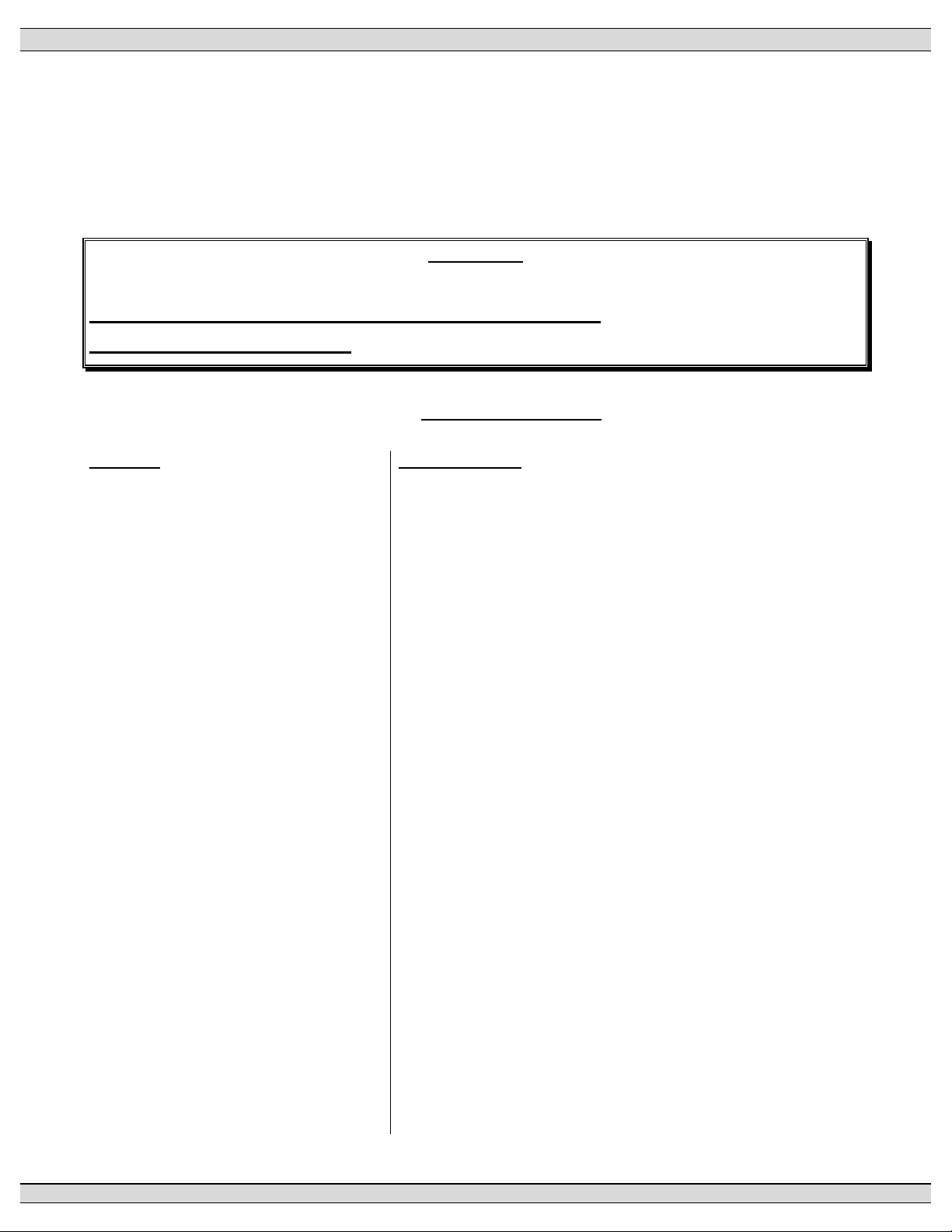
TSC 80e TRANSFER SWITCH CONTROLLER
7. TROUBLESHOOTING
A number of problems can cause the TSC 80e controller not to function properly. Refer to the
following list of typical problems. Consult the factory for any detailed information or for any problems
not listed.
CAUTION!!!
Before opening the Transfer Switch enclosure to perform any service task, it is imperative to
isolate the transfer switch from any possible source of power. Failure to do so may result in
serious personal injury or death due to electrical shock.
Service procedures must be undertaken by qualified personnel only!
Symptom Possible Causes
- Will not re-transfer to utility source
upon restoration
- Utility voltage is outside the pre-programmed limits (check
- A loose control connection
- Faulty limit switch contact in the ATS motor circuit
- Defective ATS Motor
- Defective TSC 80e controller (verify output signals with
- TSC 80e has “Transfer Fail” alarm activated which is
- Will not transfer to generator source
upon failure of utility source
- Warm-up time delay function has not timed out (verify TSC
- A loose control connection
- Faulty limit switch contact in the ATS motor circuit
- Defective ATS Motor
- Defective TSC 80e controller (verify output signals with
- TSC 80e has “Transfer Fail” alarm activated which is
- Transfer to generator source without a
power failure in the utility source
- Loose or broken wire to the utility voltage sensing terminals
- Utility supply voltage is slightly below voltage sensing
- A test mode has been activated
utility source for adequate voltage)
circuit board mounted diagnostic LED’s)
indicated by a flashing “Load on Utility” LED which is located
on the Lexan faceplate and/or a message on the LCD.
Determine cause of alarm and rectify before TSC 80e is
reset
- Generator set not producing enough voltage/frequency or
output circuit power switching device open
80e timer setting)
circuit board mounted diagnostic LED’s)
indicated by a flashing “Load on Generator” LED which is
located on the Lexan faceplate. Determine cause of alarm
and rectify before TSC 80e is reset
-
A test mode has been activated
-
Defective TSC 80e controller (verify output signals with
circuit board mounted diagnostic LED’s)
on the TSC 80e controller
setpoints. Compare TSC 80e program voltage setpoints
with actual utility voltage.
PM091 Rev 1 09/02/27 Thomson Technology
55
Page 60

TSC 80e TRANSFER SWITCH CONTROLLER
current condition (Service Entrance type ATS) and TSC 80e
Symptom Possible Causes
- Utility power switching device has tripped due to an over
“Transfer Fail” alarm activated. Determine cause of alarm
and rectify before TSC 80e is reset
- Generator does not start up or stop
when it should
- No time delay when there should be - Verify time delay function setting of TSC 80e controller
- power is not available at the load
terminals but the utility or generator
power switching device appears to be
closed to a live source
- Engine runs for no apparent reason - Verify the TSC 80e has not been set for test operation.
-
Verify remote engine control panel is set for automatic
mode.
Verify the FTS4 selector is not in the Off, Engine Start or
Test positions
Verify load bus voltage decay during transfer to enable
neutral delay timer
- The power switching device's trip unit (service entrance type
ATS) has tripped on a fault on the system. Correct the fault,
and manually reset the power switching device in the
transfer switch by moving it off and then on again with the
manual operating handle
- Load on Generator or Load on Utility
indication Lights are not operative
- Controller does not accept a new
USER password value when entered
- Verify the generator or Utility ATS mechanism limit switch is
closed to make correct signal feedback to the controller,
load voltage is present and load voltage sensing is correctly
wired to the controller from the mechanism load terminals.
The USER password can be modified only when the
MASTER Password is used and the “SET PASSWORD”
prompt is displayed.
8. TSC 80e REPLACEMENT PARTS
The TSC 80e controller is comprised of 3 component pieces, which may be ordered as replacement
parts as follows:
TSC 80e Controller Board c/w Lexan Face plate & rear cover - Part Number TSC80eSR
When ordering replacement parts please provide the following information:
1. Transfer Switch Model code (e.g. TS 873AA0200AS)
2. Transfer Switch Serial Number (e.g. W-022345)
The above information can be found on the transfer switch rating plate located on the outside of the
ATS door.
There are no user serviceable/replaceable components located
on the TSC 80e printed circuit board. If the TSC 80e controller
is deemed to be defective it must be returned to the Thomson
PM091 Rev 1 09/02/27 Thomson Technology
NOTE
56
Page 61

TSC 80e TRANSFER SWITCH CONTROLLER
Technology Factory for repair or replacement. Please refer to
SECTION 9 for further details on product return procedures.
9. PRODUCT RETURN POLICY
Thomson Technology uses a Return Material Authorization (RMA) process. Please complete the
Return Authorization Request Form (available on our web page) for return of goods, warranty
replacement/repair of defective parts, or credit consideration and fax to the appropriate department.
Returns only: Sales Fax (604) 888-5606
Warranty replacement/Warranty Repair: Service Fax (604) 888-3370.
Upon receipt of your request, Thomson Technology will confirm with a copy of our Order
Acknowledgement via fax advising the RMA number which should be used to tag the defective
controller prior to shipment.
PM091 Rev 1 09/02/27 Thomson Technology
57
Page 62

TSC 80e TRANSFER SWITCH CONTROLLER
10. NOTES
________________________________________________________________________________
________________________________________________________________________________
________________________________________________________________________________
________________________________________________________________________________
________________________________________________________________________________
________________________________________________________________________________
________________________________________________________________________________
________________________________________________________________________________
________________________________________________________________________________
________________________________________________________________________________
________________________________________________________________________________
________________________________________________________________________________
________________________________________________________________________________
________________________________________________________________________________
________________________________________________________________________________
________________________________________________________________________________
________________________________________________________________________________
________________________________________________________________________________
________________________________________________________________________________
________________________________________________________________________________
________________________________________________________________________________
________________________________________________________________________________
________________________________________________________________________________
________________________________________________________________________________
________________________________________________________________________________
________________________________________________________________________________
________________________________________________________________________________
________________________________________________________________________________
________________________________________________________________________________
________________________________________________________________________________
________________________________________________________________________________
________________________________________________________________________________
________________________________________________________________________________
________________________________________________________________________________
________________________________________________________________________________
PM091 Rev 1 09/02/27 Thomson Technology
58
 Loading...