

Page 1
DTH200CHASSIS
Page 2

DTH200CHASSIS
Page 3

DTH200CHASSIS
Page 4

DTH200CHASSIS
Page 5

DTH200CHASSIS
Page 6

DTH210E / 220E
4 First issue 07 / 02
Power requirements :
Alimentation requise :
Stromversorgung : AC 230 V 50 Hz
Requisiti di alimentazione :
Requisitos de alimentación :
Power consumption :
Puissance consommée :
Leistungsaufnahme : 15 W (approx. 2,5 W in standby)
Consumo di energia :
Consumo de energía :
Disc formats : (1) DVD-Video disc : PAL and NTSC 12/8 cm single-sided, single-layer
Format des disques : 12/8 cm single-sided, double-sided
Discformate : 12/8 cm double-sided, single-layer
Formati disco : 12/8 cm double-sided, double-layer
Formatos dediscos : (2) Compact disc Audio : 12/8 cm disc
Standard :
Standard : PAL 50-60 Hz
Norm : NTSC
Standard :
Estandar :
Frequency response :
Reponse de fréquence : DVD linear audio 48 kHz sampling : 4 Hz to 22 kHz
Frequenzbereich : DVD linear audio 96 kHz sampling : 4 Hz to 44 kHz
Risposta in frequenza : CD audio : 20 Hz to 20 kHz
Respuesta de frecuencia :
Signal to noise ratio :
Rapport signal/bruit :
Rauschabstand : 110 dB
Audio signal output Rapporto segnale/disturbo :
Signal de sortie Audio Relación señal/ruido :
Digitales audiosignal
Segnale audio di uscita Dynamic range:
Salida de la señal de audio Plage dynamique : DVD linear audio: 100 dB
Dynamic : CD audio: 100 dB
Range dinamico :
Margen dinámico :
Total harmonic distortion :
Distortion des harmoniques totales :
Gesamtklirrfaktor : 0.005%
Distortione armonica totale :
Distortión armónica total :
Pickup Wave length :
Tête de lecture Longueur d'onde :
Laser Wellenlänge : 655 / 780 nm LASER CLASSE 2
Pick-up Lunghezza d'onda :
Fonocaptor Longitud de onda :
TECHNICAL DATA - CARACTERISTIQUES TECHNIQUES TECHNISCHE DATEN - DATI TECNICI - DATOS TECNICOS
• THOMSON Multimedia reserves the right to change the specifications without notice.
• Tous droits de modification des spécifications réservés.
• Änderungen der technischen Daten sind ohne Ankündigung möglich.
• Con riserva di modifica dei dati tecnici senza preavviso.
• Nos reservamos el derecho de modificar los datos técnicos sin previo aviso.
Page 7

AC Alternative Current
AGC Automatic Gain Control
ALPC Automatic Laser Power Control
CD Compact Disc
CLV Constant Linear Velocity
CSS Contents Scramble System
DTS Digital Theater System
DVD Digital Versatile Disc
EFM Eight to Fourteen Modulation
EQ Equalizer
FE Focusing Error
FG Frequency Generator
LD Laser Diode
LPCM Linear Pulse Code Modulation
MIRR Mirror
MPEG Moving Picture Expert Group
PCB Printed Circuit Board
PLL Phase Locked Loop
PWM Pulse Width Modulation
RF Radio Frequency
S/N Signal to Noise
SMPS Switching Mode Power Supply
TE Tracking Error
TZC Track Zero Cross
VBR Variable Bit Rate
Abbreviations - Abreviations - Abkürzungen - Abbreviazioni - Abreviaciones
Page 8
DTH210E / DTH220E
14 First issue 07 / 02
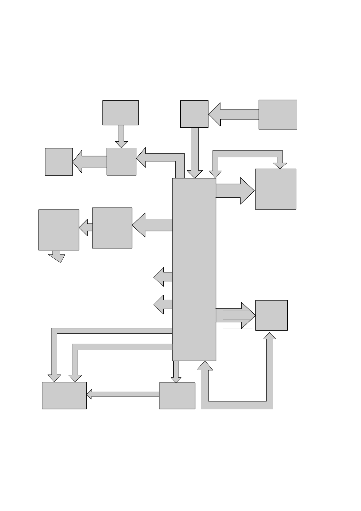
MOTOR
IC
CONTROL
STI 5519
CPU
CONTROL SIGNAL
CONTROL SIGNAL
CONTROL
SIGNAL
INFRARED SIGNAL
INFRARED
REMOTE
CONTROL
FRONT
PANAL KEY
PAD
RECEIVER
CONTROL SIGNAL
16 BITS DATA BUS
16 BITS DATA BUS
64MB
SDRAM
(FOR VIDEO)
8MB
FLASH
MEMORY
ADDRESS
BUS
ADDRESS
BUS
(THOMSON)
VFD
DISPLAY
DISPLAY
DRIVER
DVD
DECK
SPDF OUTPUT
(COAXIAL)
VIDEO OUTPUT
(COMPOSITE, SCART)
2 CHANNELS
DAC
(CS 4392)
2 CHANNELS
LOW
PASS FILTER
2XRCA
AUDIO
OUTPUT
DIGITAL CLK
AND DATA
I2 BUS
GENERAL BLOCK DIAGRAM - SYNOPTIQUE GÉNÉRAL
BLOCKSCHALTBILD ALLGEMEIN - SCHEMA A BLOCCHI GENERALE
ESQUEMA DE BLOQUES GENERAL
Page 9

16
DTH210E / DTH220E
First issue 07 / 02 15
POWER SUPPLY SCHEMATIC DIAGRAM - SCHEMA DES CIRCUITS D’ALIMENTATIONS - SCHALTBILD NETZTEIL - SCHEMA DEI CIRCUITI DI ALIMENTAZIONE
ESQUEMA DE LOS CIRCUITOS DE ALIMENTACIÓN
12
11 14T
6T
3T
1T
2T
26T
27T
7T
10
9
8
7
6
1
2
3
4
5
(EXTRA)
(90VAC-250VAC)
Mainsvoltage
50HZ / 60HZ
J801
(DTH220E)
POWE
Part of board connected to mains supply.
Partie du châssis reliée au secteur.
Primärseite des Netzteils.
Parte dello châssis collegata alla rete.
Parte del chassis conectar a la red.
Achtung :
Bei Messungen im Primärnetzteil
- Primärnetzteilmasse verwenden ( ).
Note :
Power Supply primary circuit measurements.
- Use only ( ) connection point.
Attention :
Mesure dans la partie primaire de l'alimentation
- Utiliser la masse du bloc alimentation ( ).
Attenzione :
misure nell'alimentatore primario
- usare massa alimentazione primario ( ).
Cuidado :
Medida en el bloque de alimentacion
- Utilizar la masa del bloque de alimentacion ( ).
Use isolating mains transformer.
Utiliser un transformateur isolateur du secteur.
Einen Trenntrafo verwenden.
Utilizar un transformador aislador de red.
Utilizzare un transformatore per isolarvi dalla rete.
Safety Part
When repairing, use original part only
Pièce de securité
N'utilisez que les pièces d'origine
Utilice solo piezas originales
Bei Ersatz nur Originalteil verwenden
Sicherheitsbauteil
Pieza de seguridad
Per la riparazione utilizzare solo componenti originali
Componenti di sicurezza
304V
362
5,8
14,9
0,1
2,5
1,4 5,7 5,1
0,1
0,7
T=10µS
500Vpp-H
(5) : standby
-5,1
-22,8 -21,8
8
12
12,1
11,3
12,2
12,9
12,7
12
5,8
5
5
5,1
0,1
5,8
5,7
5,7
12,9
Page 10
17
DTH210E / DTH220E
18 First issue 07 / 02
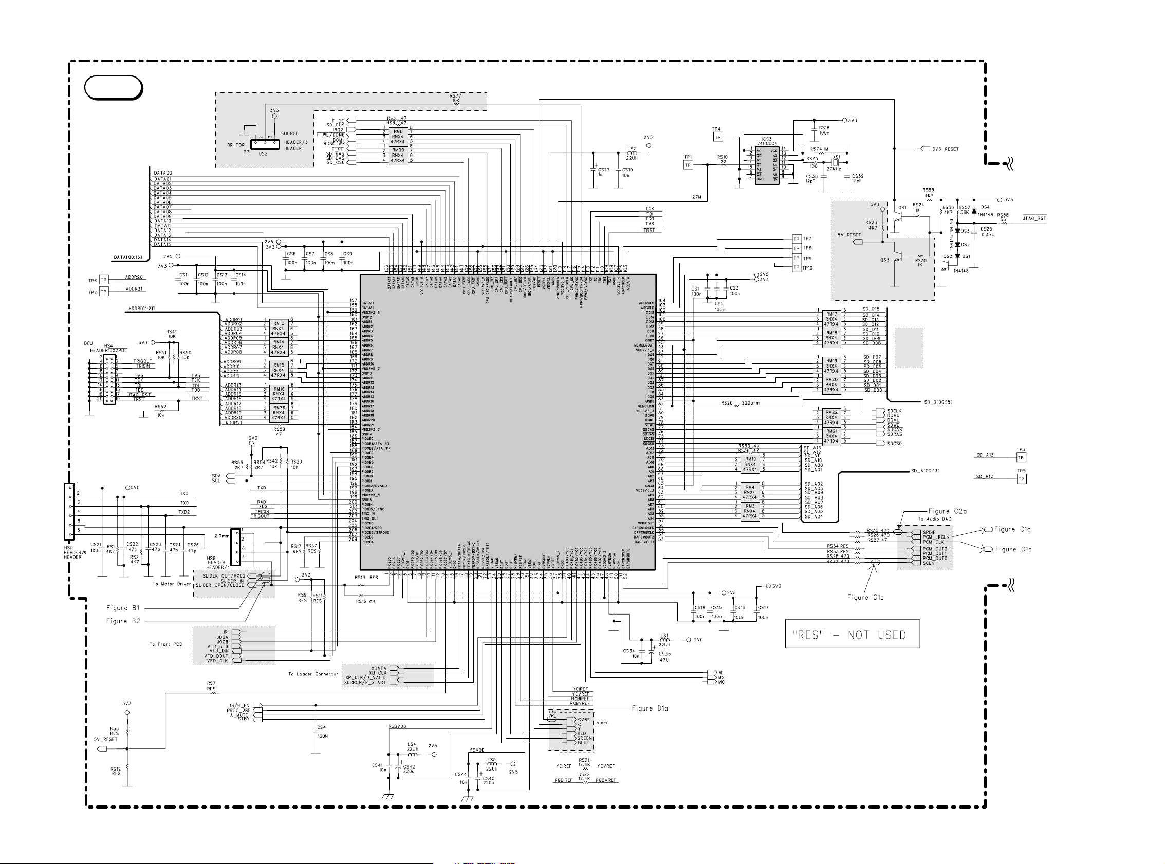
MAIN SCHEMATIC DIAGRAM - SCHEMA DE LA PLATINE PRINCIPALE - SCHALTBILD HAUPTPLATINE - SCHEMA DELLA PIASTRA PRINCIPALE- ESQUEMA DE LA PLATINA PRINCIPAL
RS232
ICS
STI 5580 / 5519 / 5508
MAIN
Page 11
20
DTH210E / DTH220E
First issue 07 / 02 19
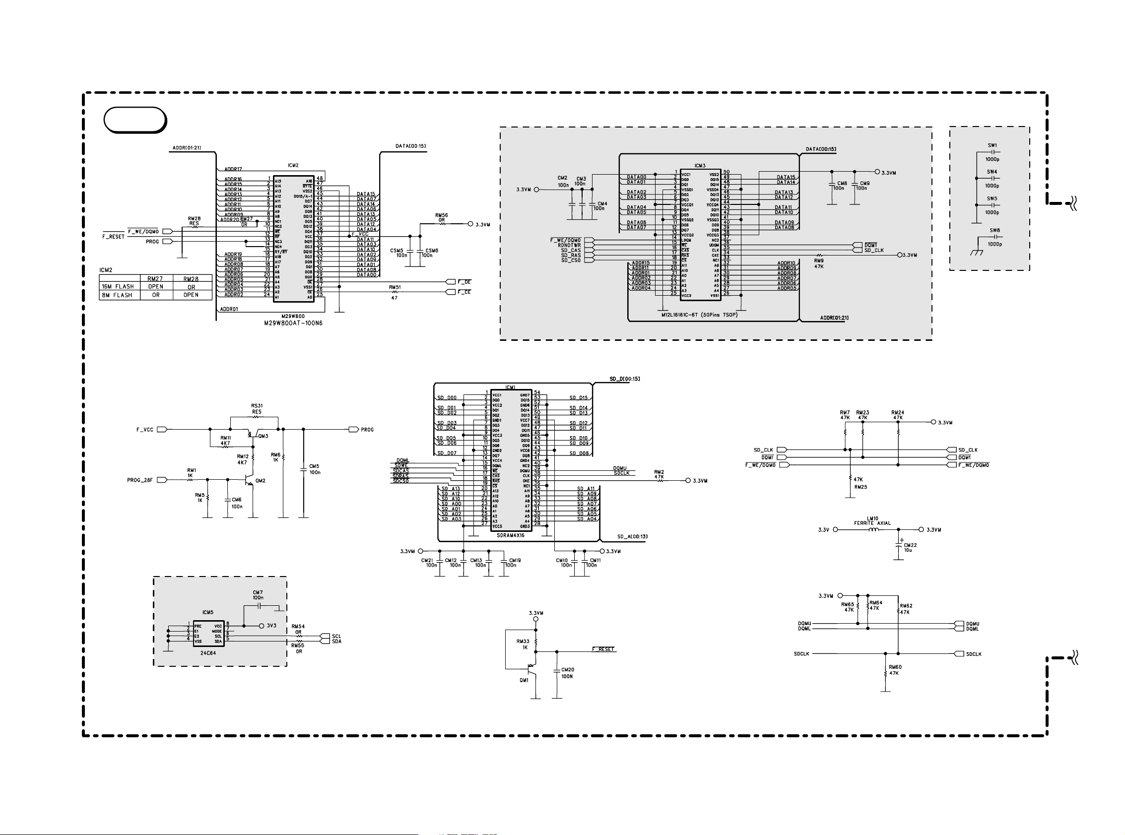
MAIN SCHEMATIC DIAGRAM - SCHEMA DE LA PLATINE PRINCIPALE - SCHALTBILD HAUPTPLATINE - SCHEMA DELLA PIASTRA PRINCIPALE- ESQUEMA DE LA PLATINA PRINCIPAL
MAIN
ICM2 ICM3
ICM1
ICM5
MEMORY
Page 12

21
DTH210E / DTH220E
22 First issue 07 / 02
MAIN SCHEMATIC DIAGRAM - SCHEMA DE LA PLATINE PRINCIPALE - SCHALTBILD HAUPTPLATINE - SCHEMA DELLA PIASTRA PRINCIPALE- ESQUEMA DE LA PLATINA PRINCIPAL
MAIN
Page 13

24
DTH210E / DTH220E
First issue 07 / 02 23
MAIN SCHEMATIC DIAGRAM - SCHEMA DE LA PLATINE PRINCIPALE - SCHALTBILD HAUPTPLATINE - SCHEMA DELLA PIASTRA PRINCIPALE- ESQUEMA DE LA PLATINA PRINCIPAL
To solve headphone distortion problem, change :
- RA41 / 42 / 35 / 36 From 1,5K to 3K 1%.
- RA38 / 43 / 32 / 37 From 3,4K to 3,6K 1%.
- RA39 / 40 / 33 / 34 From 1,87K to 2,7K 1%.
- CA 41 / 37 From 3,3n to 1,5n.
To match Scart BD and H/P BD, change RA1 / RA17 from RES to OR.
The parts in rectangle are of no use for DVD220.
To match Scart Mute, change QA5 / QA6 from RES to M6.
To update DWG, RA28 / RA29 / RA49 change from RES to OR, RA50 / 51 / 52 change from OR to RES.
HEADPHONE AMPLIFIER
MAIN
AMPL
Page 14

25
DTH210E / 220E
26 First issue 07 / 02
KEYBOARD SCHEMATIC DIAGRAM - SCHEMA DES CIRCUITS COMMANDES - SCHALTBILD BEDIENTEIL - SCHEMA DEI CIRCUITI TASTIERA - ESQUEMA DE LOS CIRCUITOS MANDOS
KDB
Page 15

28
DTH210E / DTH220E
First issue 07 / 02 27
SCART INTERFACE SCHEMATIC DIAGRAM - SCHEMA DE L’INTERFACE PERITELEVISION - SCHALTBILD EUROPA NORMBUCHSE - SCHEMA DELLA PRESA PERITEL
ESQUEMA INTERFAZ EUROTOMA
SKC
Page 16

29
DTH210E / DTH220E
30 First issue 07 / 02
COMPONENT SIDE - COTÉ COMPOSANTS - BESTÜCKUNGSSEITE - LATO COMPONENTI - LADO COMPONENTES
POWER SUPPLY CIRCUIT BOARD - CIRCUIT IMPRIME DE L’ALIMENTATION - LEITERPLATTE NETZTEIL - PIASTRA DEI CIRCUITI DI ALIMENTAZIONE - PLATINA ALIMENTACIÓN
Page 17

32
DTH210E / DTH220E
First issue 07 / 02 31
MAIN PRINTED CIRCUIT BOARD - CIRCUIT IMPRIME PLATINE PRINCIPALE - GRUNDPLATTE - PIASTRA PRINCIPALE - PLATINA PRINCIPAL
COMPONENT SIDE - COTÉ COMPOSANTS - BESTÜCKUNGSSEITE - LATO COMPONENTI - LADO COMPONENTES
Page 18

33
DTH210E / DTH220E
34 First issue 07 / 02
MAIN PRINTED CIRCUIT BOARD - CIRCUIT IMPRIME PLATINE PRINCIPALE - GRUNDPLATTE - PIASTRA PRINCIPALE - PLATINA PRINCIPAL
SOLDER SIDE - COTÉ CUIVRE - LÖTSEITE - LATO SALDATURE - LADO DEL COBRE
Page 19

37
DTH210E / DTH220E
38 First issue 07 / 02
KEYBOARD CIRCUIT BOARDS - CIRCUITS IMPRIMES PLATINES COMMANDES - LEITERPLATTE BEDIENTEIL - PIASTRE TASTIERA - PLATINAS MANDOS
COMPONENT SIDE - COTÉ COMPOSANTS - BESTÜCKUNGSSEITE - LATO COMPONENTI - LADO COMPONENTES
SOLDER SIDE - COTÉ CUIVRE - LÖTSEITE - LATO SALDATURE - LADO DEL COBRE
Page 20

SCART INTERFACE P.C.B. - PLATINE INTERFACE PERITELEVISION -LEITERPLATTE EUROPA NORMBUCHSE - PIASTRA PRESA PERITEL - PLATINA INTERFAZ EUROTOMA
COMPONENT SIDE - COTÉ COMPOSANTS - BESTÜCKUNGSSEITE - LATO COMPONENTI - LADO COMPONENTES
SOLDER SIDE - COTÉ CUIVRE - LÖTSEITE - LATO SALDATURE - LADO DEL COBRE
DTH210E / DTH220E
First issue 07 / 02 35
36
Page 21

DTH210 / DTH220
First issue 07 / 02 39
COMPONENT SIDE - COTÉ COMPOSANTS - BESTÜCKUNGSSEITE - LATO COMPONENTI - LADO COMPONENTES
HEADPHONE AMPLIFIER PCB - PLATINE AMPLIFICATEUR CASQUE - LTP
KOPFHÖRERENDVERSTÄRKER - PIASTRA AMPLIFICATORE PER CUFFIA PLATINA AMPLIFICADOR DE LOS AURICULARES
SOLDER SIDE - COTÉ CUIVRE - LÖTSEITE - LATO SALDATURE - LADO DEL COBRE
Page 22

AAAAA
EN FR DE IT ES
A
HANDLING THE OPTICAL PICKUP
The laser diode used in the optical pickup may
break down due to potential differences caused by
electricity produced by clothing or the human body,
care should therefore be taken to prevent
electrostatic discharge whilst repairing the optical
pickup.
The following method is recommended.
1) Place a conductive sheet on the work bench
(The black sheet used for wrapping repair
parts.)
2) Place the set on the conductive sheet so that
the chassis is grounded to the sheet.
3) Place your hands on the conductive sheet
(doing this gives them the same ground as the
sheet.
4) Remove the optical pickup block
5) Perform work on top of the conductive sheet. Be
careful not to let your clothes or any other static
sources to touch the unit.
* Grounding the Human Body, use an antistatic
wrist strap to discharge static electricity from
your body.
* Grounding the work place, use either an
antistatic matt or a sheet of steel on the area
where the optical pickup is to be placed and
ground the matt/sheet.
6) Short the short terminal on the PCB, which is
inside the Pickup Assembly, before
deconnecting the flexible cable for replacing the
Pickup. (The short terminal is shorted when the
Pickup Assembly is being lifted or moved.)
7) After replacing the Pickup, open the short
terminal on the PCB.
MANIPULATION DU BLOC OPTIQUE
La diode laser utilisée dans le bloc optique peut se
détériorer à cause d’une différence de potentiel
causé par l’électricité produite par les vêtements ou
le corps humain, par conséquent des précautions
doivent être prise pour éviter les décharges
électrostatiques pendant la réparation du bloc
optique.
Il est recommandé de suivre la méthode suivante.
1) Placez une feuille conductrice sur le banc de
travail (la feuille noire utilisée pour envelopper
les pièces détachées).
2) Placez l’ensemble sur la feuille conductrice pour
que le châssis soit mis à la masse par la feuille.
3) Mettez vos mains sur la feuille conductrice (en
faisant ceci, vous leur donnez la même masse
que la feuille)
4) Retirez le bloc optique
5) Travaillez en haut de la feuille conductrice.
Prenez soin de ne pas laisser vos vêtements ou
autre source statique toucher le bloc optique.
* Mise à la terre du corps humain : utilisez un
bracelet antistatique pour décharger l’électricité
statique de votre corps.
* Mise à la terre du poste de travail : placez soit
un tapis antistatique, soit
une feuille d’acier sur le banc de travail où vous
poserez le bloc optique après avoir relier le
tapis ou la feuille à la masse.
6) Pour remplacer le bloc optique, soudez le courtcircuit sur le circuit imprimé qui se trouve sur
l’ensemble optique, avant de déconnecter le
câble flexible (le court-circuit est soudé lorsque
l’ensemble optique est levé ou déplacé).
7) Après le remplacement du bloc optique,
dessoudez le court-circuit sur le circuit imprimé.
HANDHABUNG DER OPTISCHEN EINHEIT
Die verwendete Laser-Diode kann unter
Umständen zerstört werden, wenn sie mit statischer
Spannung aufgeladene Teile in Berührung kommt .
Deshalb ist unbedingt zu beachten, daß vor der
Reparatur alle Teile potentialfrei sind.
Empfehlenswert ist folgende Methode.
1) Eine leitende Unterlage auf den Werktisch
legen (über 1MOhm Widerstand geerdete
Leitgummi-Matte, Metallplatte oder ggf. die
schwarze Folie der Ersatzteilverpackung).
2) Das Gerät auf diese Fläche stellen, damit ein
Potenzialausgleich stattfinden kann.
3) Bringen Sie Ihren Körper auf das gleiche
Potenzial wie die Unterlage (z.B. mit
Handgelenkband über 1 MOhm geerdet).
4) Jetzt kann das DVD-Laufwerk bzw. die optische
Einheit ausgebaut werden .
5) Führen sie alle Arbeiten auf der LeitgummiMatte aus.
6) Zum Schutz des Lasers verbinden vor dem
Ausbau der optischen Einheit (Lösen der
Flachbandleitung) die beiden Lötpunkte auf
der Leiterplatte der optischen Einheit
miteinander. Die Leiterplatte befindet sich in der
optischen Einheit.
7) Nach dem Einbau der (neuen) optischen Einheit
den Kurzschluß wieder beseitigen !
MANEGGIAMENTO OTTICA PICKUP
Il diodo laser usato nelle ottiche pickup si può
danneggiare a causa di differenze di potenziale
causate da elettricità prodotta da vestiti o dal corpo
umano, particolari attenzioni devono essere prese,
durante la riparazione di apparecchiature con
pickup ottici, per prevenire scariche elettrostatiche.
Si raccomanda di seguire le seguenti indicazioni.
1) Mettere un foglio conduttivo sul banco di lavoro
(tipo foglio nero utilizzato per avvolgere le parti
di ricambio).
2) Posizionare l’apparecchiatura sul foglio
conduttivo per collegare la massa del telaio al
foglio conduttivo.
3) Toccare con le mani il foglio conduttivo per
avere lo stesso potenziale di massa del foglio
conduttivo.
4) Rimuovere l’assieme ottica pickup.
5) Lavorare sopra il foglio conduttivo. Evitare di far
toccare i propri vestiti o qualsiasi altra sorgente
statica all’apparecchiatura.
* Per scaricare a massa l’elettricità statica del
proprio corpo utilizzare l’apposito braccialetto
antistatico.
* Per mettere a terra il proprio posto di lavoro
utilizzare un tappetino antistatico o un foglio di
acciaio collegati a massa, sull’area dove deve
essere sostituita l’ottica.
6) In caso di sostituzione del pick up,
cortocircuitare prima gli appositi punti della
piastrina dell’assieme pickup, poi scollegare il
cavo di collegamento flessibile.
7) Aprire il cortocircuito dei terminali solo dopo la
sostituzione del Pickup.
MANEJO DEL CONJUNTO OPTICO
El diodo láser utilizado en el lector óptico puede
resultar averiado a causa de las diferencias de
potencial eléctrico producidas por el roce con la
ropa o con el cuerpo humano, también hay que
tener cuidado de que no se produzcan descargas
electrostáticas mientras se repara el lector óptico.
Se recomienda el siguiente método.
1) Colocar una hoja conductora en el banco de
trabajo (Vale la hoja negra que se utiliza para
envolver los repuestos).
2) Colocar el aparato en la hoja conductora de
forma que el chasis haga contacto con la hoja.
3) Poner las manos sobre la hoja conductora
(haciendo esto se da la misma toma de tierra
que a la hoja).
4) Retirar el conjunto óptico.
5) Realice el trabajo encima de la hoja conductora.
Tenga cuidado para no permitir que su ropa o
cualquier otra fuente de electricidad estática
pueda tocar a la unidad.
* Conecte a tierra el cuerpo humano, utilizando
una muñequera antiestática para descargar la
electricidad estática del cuerpo.
* Conectar a tierra el lugar de trabajo, utilizando
una alfombrilla antiestática o una hoja de papel
de aluminio en el área donde
se coloque el lector óptico y conectándola a la
toma de tierra.
6) Poner en cortocircuito los terminales de los
diodos (soldaduras en la cinta del conjunto
óptico) antes de desconectar el cable flexible
para remplazar el lector óptico.
7) Después de cambiar el lector óptico, quitar los
cortocircuitos anteriores.
Fig. 1
Fig. 2 Fig. 3
DTH210E / DTH220E
First issue 07 / 02 7
8
Page 23

MECHANISM MAINTENANCE
In the following chapters, the reference marks of
spare parts indicate the dissassembling order. Unless
otherwise stated, reassemble in the reverse order.
REMOVAL / REFITTING
1- Access to DVD assembly
Remove the 7 screws and the top cabinet.
2 - Removing the DVD player
Remove the 4 screws fixing the DVD player.
3 - Removing the shield (fig. 4)
Disengage: and
4 - Replacing the tray (fig. 5)
Disengage:
Push:
5 - Replacing the belt (fig. 5 to fig. 8)
Unscrew:
Remove: and
Push:
Slide:
Remove: , , and
6 - Replacing the optical pick-up (fig. 9 and fig. 10)
Unsolder:
Disengage:
Remove:
Unscrew:
Remove: and
HOW TO OPEN A FAULTY TRAY (FIG.11)
Insert a screw driver into the emergency hole:
Slide the plastic slot in the direction of the
arrow to open the DVD tray.
MAINTENANCE DE LA MÉCANIQUE
Dans les chapitres suivants, le repérage des pièces
indique l'ordre de démontage. Sans indication
contraire, le remontage se fait dans l'ordre inverse.
DÉMONTAGE / REMONTAGE
1 - Accès à l'ensemble DVD
Retirer les 7 vis et le coffret supérieur.
2 - Dépose de l'ensemble DVD
Retirer les 4 vis maintenant le lecteur de DVD.
3 - Dépose du blindage (fig. 4)
Dégager: et
4 - Remplacement du tiroir (fig. 5)
Dégager:
Tirer:
5 - Remplacement de la courroie (fig. 5 à fig. 8)
Dévisser:
Retirer: et
Pousser:
Glisser:
Retirer: , , et
6 - Remplacement du bloc optique (fig. 9 et fig. 10)
Dessouder:
Dégager:
Retirer:
Dévisser:
Retirer: et
COMMENT OUVRIR UN TIROIR DÉFAILLANT
(FIG.11)
Glisser un tournevis plat dans la fente
Déplacer la languette de gauche à droite
pour ouvrir le tiroir du DVD.
WARTUNG DES LAUFWERKS
In den folgenden Absätzen kennzeichnet die
Numerierung der Teile die Reihenfolge der
Demontage. Wenn nicht anders vermerkt, erfolgt
der Zusammenbau in umgekehrter Reihenfolge.
AUSBAU / EINBAU
1 - Zugang zum DVD-Laufwerk
Entfernen Sie 7 Schrauben und den Gehäusedeckel
2 - Ausbau des DVD-Laufwerkes
Entfernen Sie 4 Schrauben und des DVD-Laufwerkes
3 - Entfernen der Abschirmung des DVD-
Laufwerkes (Abb. 4)
Aushaken: und
4 - Austausch der Schublade (Abb. 5)
Aushaken:
Herausziehen:
5 - Austausch der Treibriemen (Abb. 5 bis Abb. 8)
Schrauben lösen:
Ausbauen: und
Wegdrücken:
In Pfeilrichtung schieben:
Ausbauen: , , und
6 - Austausch der optischen Einheit (Abb. 9 und 10)
Loflöten:
Aushaken:
Ausbauen:
Schrauben lösen:
Ausbauen: und
DEFEKTE DVD-SCHUBLADE ÖFFNEN
(FIG.11)
Stecken Sie einen Schraubendrehen in den
Notöffnungsschlitz
Schieben Sie den Kunststoffschieber in
Pfeilrichtung um die Schublade zu öffnen.
MANUTENZIONE DELLA MECCANICA
I riferimenti delle parti di ricambio, indicati nei
seguenti capitoli, si riferiscono all’ordine di
smontaggio. Dove non specificato riassemblare in
ordine inverso.
SMONTAGGIO / RIMONTAGGIO
1 - Accesso all'assieme DVD
Rimuovere le 7 viti e il coperchio.
2 - Rimovuere il lettore DVD
Rimuovere le 4 viti che fissano il littore DVD.
3 - Rimovuere la schermature del DVD (Fig. 4)
Sganciare: e
4 - Sostituzione del cassetto (fig. 5)
Sganciare:
Tirare:
5 - Sostituzione della cinghia (Fig. 5 alla fig. 8)
Svitare:
Rimuovere: e
Spingere:
Far scivolare:
Rimuovere:
,
,e
6 - Sostituzione del Pickup
Dissaldare
Sganciare:
Rimuovere:
Svitare:
Rimuovere: e
COME APRIRE IL CASSETTO IN CASO DI
ANOMALIA (FIG.11)
Inserire un cacciavite nel foro di emergenza
Far slittare la linguetta di plastica nella
direzione indicata dalla freccia per aprire il
cassetto DVD.
MANTENIMIENTO DEL MECANISMO
En los siguientes epígrafes, las marcas de
referencia de repuestos indican el orden de
desensamblaje. A no ser que se diga otra cosa, el
reensamblaje es en el orden inverso.
DESMONTAJE / MONTAJE
1 - Acceso al conjunto DVD
Retirar los 7 tornillos y la tapa superior.
2 - Retirar el DVD
Retirar los 4 tornillos y el DVD
3 - Retirar el blindaje del DVD (Fig. 4)
Desenganchar:
4 - Sustitución de la bandeja (fig. 5)
Desenganchar:
Tirar:
5 - Sustitución de la cinta (fig. 5 a fig. 8)
Desatornillar:
Retirar: y
Empujar:
Deslizar:
Retirar:
,
,y
6 - Sustitución del conjunto optico
Desoldar:
Desenganchar:
Retirar:
Desatornillar:
Retirar: y
COMO ABRIR MANUALMENTE LA BANDEJA
(FIG. 11)
Insertar un destornillador en la ranura de
emergencia
Desplazar la pieza de plástico en
la dirección de la flecha para abrir la b
andeja del
DVD.
20
19
18
17
16151413121110
09
08
07
06
05
040301
20
19
18
17
16151413121110
09
0807060504
030201
20
19
18
17
16151413121110
09
08
07
0605040302
01
20
19
18
17
16151413121110
09
080706
05
04
030201
20
19
18
17
16151413121110
09
08
07
06
05
04
030201
9
DTH210E / DTH220E
10 First issue 07 / 02
EN FR DE IT ES
Page 24

15
DTH210E / DTH220E
First issue 07 / 02 11
01
Fig. 9
Fig. 10
Fig. 8
11
12
Fig.11
20
Fig. 4
Fig. 5
Fig. 6
Fig. 7
11
02
03
04
10
14
05
13
03
06
17
18
17
14
01
17
19
07
Page 25

MODULES
MAIN MAIN (MPEG)
35680630
SMPS SMPS
35592410
SKC SKC
35592420
KDB KDB
35589800
LED LED
35589830
I
IC201 NJM2277M FLAT
35592450
IC202 MC14053BCP
46006700
IC60 LB1641
20656300
ICA1,4 LM833D FLAT
21104740
ICA7 UPC78L05J
10247310
ICM1 UPD4564163G5-A80-9JF FLAT
35592540
ICM2 SST39VF800A-70-4C-EK FLAT
35154480
ICS1 STI5519 FLAT
55130350
ICS2 AMS2501CS-2.5
35199410
ICS3 M74HCU04M1R FLAT
25416710
U801 TOP223P
35151270
U802 PC817
35151260
U803 NJM431
35151280
U804,805 PQ05RD11
15675070
U807 MC78L08/ACP
46007200
UA1 CS4392-KZ FLAT
21198070
UP1 M6759 FLAT
35592430
UP2 UPD16315 FLAT
35592440
UP3 GP1U271R
35109650
T
Q600,QA2,4, 2SA812-BM7 SMD
20434650
7,8,QM1,3,
QV201,207
Q601,QA1,3,5, 2SC1623 SMD
16005580
6,13,QF3,4,
QM2,QP1,2,3,4,
QS1,2,3,
QV202,203,204,
205,206,208,209,
210
Q801 2SB772Q
35056860
Q802,806,QF1 9014C
10400150
Q803,805,807, 9015C
10390820
QF2
D
D601,602,604, LL4148 SMD
16012450
DN1,2,
DS1,2,3,4
D603 BZT55C6V8 SMD
15080480
D801,802,803, RGP30MT
10450220
804,812,815,
820
D805 BYV26C 600V 1A
35150800
D806,814,816, 1N4148
44009209
817,818,819,822,
DP2,3,4,5,
6,7,8,10,11
D807,808 SB360
10340510
D809 SR160 60V 1A
35193790
D810,811,821 HER105 400V 1A
35150790
LED1 LED
35150780
Z802,804 BZX55B5V1/ZPD5V1 2%
44035702
Z803 BZX55C12V
30948800
ZF1 ZPD4,7/BZX55C4V7
20475400
ZP1 BZX55B5V6/ZPD5V6 2%
70438200
F
XP1 11M0592HZ
10394580
XS1 27M0HZ
35174570
R
R807 1K91 OHM 1% 0,25W
15013150
R808 4K7 OHM 1% 0,40W
13065890
R815 39K OHM 5% 5W
35151230
R836 23K7 OHM 1% 0,16W
35592300
C
C801 0,22U0F 20% 275V
35151170
C802 33U0F 20% 400V
35151010
C806 2200PF 20% 250V
35151000
C828 220P0F 10% 1K0V
25460410
S
L801
35151240
T801 NC-H0074-9
35592310
OTHER PARTS
AUTRES PIECES
SONSTIGE TEILE
ALTRE PARTI
OTRAS PIEZAS
F801 1A25T TIME-LAG FUSE
48006800
1A25T FUSIBLE TEMPORISE
1A25T SICHERUNG
1A25T FUSIBILE TEMPORRIZ.
1A25T FUSIBLE TEMPORIZ.
PS1 SCART SOCKET
35151300
PRISE PERITEL
EURO-AV-BUCHSE
EUROPRESA NORMALIZZATA
EUROCONECTOR
RCA20 CINCH SOCKET
35154350
PRISE CINCH
CHINCH-BUCHSE
PRESA CINCH
TOMA CINCH
RL801 RELAY 5VDC
35592400
RELAIS 5VDC
RELAIS 5VDC
RELE 5VDC
RELE 5VDC
SW1,2,3,4,5, MICROSWITCH
20540300
6,7,8 MICRO CONTACTEUR
MIKROSCHALTER
MICROINTERRUTTORE
MICROCONTACTOR
VFD1 DISPLAY
35589820
AFFICHEUR
ANZEIGE
VISUALIZZATORE
VISUALIZADOR
VID20 CINCH SOCKET 4 ASSY
35592460
ENSEMBLE 4 PRISES CINCH
CHINCH 4 BUCHSEN-EINHEIT
ASSIEME 4 PRESA CINCH
CONJUNTO 4 TOMA CINCH
THOMSON
DTH210E
Chassis DTH200
PARTS LIST
LISTE PIECES DETACHEES
ERSATZTEILLISTE
LISTA PARTI DI RICAMBIO
LISTA DE PIEZAS DE REPUESTO
VIDEO
No copying, translation, modification on other use authorized. All rights reserved worldwide. • Tous droits de reproduction, de traduction, d'adaptation et d'exécution réservés pour tous les pays. • Sämtliche Urheberrechte an diesen Texten und Zeichnungen stehen uns zu. Nachdrucke,
Vervielfältigungen - auch auszugsweise - nur mit unserer vorherigen Zustimmung zulässig. Alle Rechte vorbehalten. • I diritti di riproduzione, di traduzione, e esecuzione sono riservati per tutti i paesi. • Derechos de reproduccion, de traduccion, de adaptacion y de ejecucion reservados para todos los paises.
For any requests, please contact THOMSON multimedia after sales service area
Pour toutes précisions, contactez votre service apres vente local THOMSON multimedia
Für weitere Auskünfte, wenden Sie sich bitte an die THOMSON multimedia Kundendienste
Per precisazioni, contattare l’assistenza tecnica THOMSON multimedia
Para cualquier pregunta, por favor contactar con el responsable de zona del servicio postventa de THOMSON multimedia
R : RECYCLED PART
: PIECE RECYCLEE
: AUSTAUSCHTEILE
: RICAMBIO RICICLATO
: MODULO REPROCESADO
VERSION 1 07 / 2002
35651670
VERSION 2 00 / 0000
1/4
Page 26

OPTICAL PLAYER
LECTEUR OPTIQUE
OPTISCHES LESESYSTEM
ASSIEME OTTICA
MECANISMO OPTICO
010 RUBBER BELT TD005
10773500
COURROIE CAOUTCHOUC TD005
ANTRIEBSRIEMEN TD005
CINGHIA DI GOMMA TD005
CORREA DE GOMA TD005
014 GEAR TRAY
10727220
PIGNON TIROIR
ZAHNRAD SCHUBLADE
PIGNONE CASSETTO
PINON CORREDERA
016 PULLY TRAY
10727230
POULIE TIROIR
ROLLE SCHUBLADE
PULEGGIA CASSETTO
POLEA CORREDERA
036 TRAY DVD
10727270
TIROIR DVD
SCHUBLADE DVD
CASSETTO DVD
CORREDERA DVD
100 OPTICAL HEAD ALONE TOP53R
10725290
TETE OPTIQUE SEULE TOP53R
LASER-ABTASTER TOP53R
SOLO TESTINA LASER TOP53R
CABEZA OPTICO SOLAMEN TOP53R
550 GEAR TRACKING
10717850
PIGNON TRACKING
ZAHNRAD TRACKING
PIGNONE TRACKING
PINON TRACKING
620 MICROSWITCH DETECTOR
25486800
MICRO CONTACTEUR DETECTEUR
MIKROSCHALTER DETEKTOR
MICROINTERRUTTORE RIVELATORE
MICROCONTACTOR DETECTOR
700 TOOTH WHEEL 1
10269530
ROUE DENTEE 1
ZAHNRAD 1
RUOTA DENTATA 1
RUEDA DENTADA 1
750 TOOTH WHEEL 2
10717760
ROUE DENTEE 2
ZAHNRAD 2
RUOTA DENTATA 2
RUEDA DENTADA 2
IM02 GP1S93
10449570
GP1S93
GP1S93
GP1S93
GP1S93
EQUIPMENT/PRESENTATION
EQUIPEMENT/PRESENTATION
AUSSTATTUNG/GEHAEUSE
PARTI VARIE
EQUIPO/PRESENTACION
RCT110DA1 REMOTE CONTROL
21182160
RCT110DA1 TELECOMMANDE
RCT110DA1 FERNBEDIENUNG
RCT110DA1 TELECOMANDO
RCT110DA1 TELEMANDO
MECHANISM
MECANIQUE
MECHANIK
MECCANICA
MECANISMO
TVM503R1 OPTICAL PLAYER + CD MECHADECK
10757650
TVM503R1 LECTEUR OPTIQUE + MECA. CD
TVM503R1 CD-LAUFWERK + CD MECHANISCHE
TVM503R1 ASSIEME OTTICA + CD MECCANICA
TVM503R1 MECANISMO OPTICO + CD MECANIS.
M
DTH210/220 SERVICE MANUAL
35651660
DTH210/220 DOC TECHNIQUE
DTH210/220 TECHNISCHE DOKUMENTATION
DTH210/220 DOCUMENTAZIONE TECNICA
DTH210/220 DOCUMENTACION TECNICA
DTH210E PARTS LIST
35651670
DTH210E LISTE DE PIECES DETACHEES
DTH210E ERSATZTEILLISTE
DTH210E LISTA PARTI DI RICAMBIO
DTH210E LISTA DE PIEZAS DE REPUESTO
DTH210E/225E UM TH F,GB,D,E,I
35191460
DTH210E/225E NU TH F,GB,D,E,I
DTH210E/225E BA TH F,GB,D,E,I
DTH210E/225E IU TH F,GB,D,E,I
DTH210E/225E IU TH F,GB,D,E,I
DTH210E/225E UM TH NL,SW,DK,P,GR
35191470
DTH210E/225E NU TH NL,SW,DK,P,GR
DTH210E/225E BA TH NL,SW,DK,P,GR
DTH210E/225E IU TH NL,SW,DK,P,GR
DTH210E/225E IU TH NL,SW,DK,P,GR
DTH210E/225E UM TH RU,PL,H,CZ,SK
35191480
DTH210E/225E NU TH RU,PL,H,CZ,SK
DTH210E/225E BA TH RU,PL,H,CZ,SK
DTH210E/225E IU TH RU,PL,H,CZ,SK
DTH210E/225E IU TH RU,PL,H,CZ,SK
CDROM DTH210E-DTH220E
35655900
CDROM DTH210E-DTH220E
CDROM DTH210E-DTH220E
CDROM DTH210E-DTH220E
CDROM DTH210E-DTH220E
MAINTENANCE TOOLS
MAINTENANCE
WERKZEUG FUER DAS
GERAET
UTENSILI DI MANUTENZIONE
MANTENIMIENTO
DTH210/220E POWER SUPPLY REPAIR KIT
35654600
DTH210/220E KIT DE MAINTENANCE ALIM
DTH210/220E REPARATURSET NETZTEIL
DTH210/220E KIT PER RIPARARE L’ALIMENTAZ
DTH210/220E KIT DE REPARACION DE L’ALIME
CHASSIS/PRESENTATION
CHASSIS/PRESENTATION
CHASSIS/GEHAEUSETEILE
PARTI VARIE
CHASIS/PRESENTACION
01 COVER UPPER
35648260
COUVERCLE SUPERIEUR
GEHAEUSEOBERTEIL
COPERCHIO SUPERIORE
TAPA SUPERIOR
05 ON/OFF BUTTON
35648250
TOUCHE MARCHE/ARRET
EIN-AUS TASTE
TASTO ACCESO/SPENTO
TECLA MARCHA/PARADA
06 BADGE-BRAND THOMSON
35648240
LOGO THOMSON
SCHRIFTZUG THOMSON
MARCHIO THOMSON
LOGOTIPO THOMSON
08 DISPLAY WINDOW
35648220
GLACE AFFICHEUR
ANZEIGEFENSTER
VETRO DEL VISUALIZZATORE
CRISTAL DEL VISUALIZADOR
10 COVER TRAY CD
35648230
CACHE TIROIR CD
ABDECKUNG SCHUBLADE CD
COPERCHIO CASSETTO CD
CUBIERTA CORREDERA CD
11 FRONT PANEL
35648210
FACADE
FRONTPLATTE
PANNELLO FRONTALE
PANEL FRONTAL
12 BUTTON STRIP 7T
35648200
BARRETTE DE TOUCHES 7T
TASTENLEISTE 7T
ASSIEME TASTI 7T
CONJUNTO DE TECLAS 7T
30 POWER SUPPLY LEAD
35151540
CORDON D’ALIMENTATION
NETZKABEL
CAVO DI ALIMENTAZIONE
CABLE DE ALIMENTACION
DTH210E 2/4
Page 27

35592420
SKC
35680630
MAIN
35589830
LED
356482500535648240
06
35589800
KDB
35648200
12
35648210
11
35648220
08
35648230
10
35151540
30
35592410
SMPS
35648260
01
DTH210E 3/4
CHASSIS/PRESENTATION / CHASSIS/PRESENTATION / CHASSIS/GEHAEUSETEILE /
PARTI VARIE / CHASIS/PRESENTACION
Page 28

THOMSON multimedia Sales Europe - S.A. au capital de 30 000 000 €- Siège : 46, Quai Alphonse Le Gallo 92100 Boulogne FRANCE - RCS NANTERRE B 322 019 464
The description and characteristics given here are of informative significance only, and non committal. To keep up the high quality of our products, we reserve the right to
make any changes or improvement without previous notice. • Les descriptions et caractéristiques figurant sur ce document sont données à titre d'information et non
d'engagement. En effet, soucieux de la qualité de nos produits, nous nous réservons le droit d'effectuer, sans préavis, toute modification ou amélioration. • Die
Beschreibungen und Daten in dieser Anleitung dienen nur zur Information und sind nicht bindend. Um die Qualität unserer Produkte ständig zu verbessern, behalten wir uns
das Recht auf Änderungen vor. • Le descrizioni e le caratteristiche date su questo documento sono fornite a semplice titolo informativo e senza impegno. Ci riserviamo il
diritto di eseguire, senza preavviso, qualsiasi modifica o miglioramento. • Las descripciones y características que figuran en este documento se dan a título de información
y no de compromiso. En efecto, en bien de la calidad de nuestros productos, nos reservamos el derecho de efectuar, sin previo aviso, cualquier modificación o mejora.
DTH210E 4/4
25486800
620
10449570
IM02
10725290
100
10717850
550
10269530
700
10717760
750
OPTICAL PLAYER / LECTEUR OPTIQUE / OPTISCHES LESESYSTEM /
ASSIEME OTTICA / MECANISMO OPTICO
10727220
10727230
10773500
014
016
010
10727270
036
Page 29

Date Issued: 11/03/04 Bulletin No.459
kkkkkkkkkkkkkkkkkkkkkkkkkkkkkkkkkkkkkkkkkkkkkkkkkkk
Brown Goods Technical Tip Issued To CSM? Yes No
DVD Thomson Model No.: DTH210
Symptom:
Cause:
Cure:
No sound from SCART socket. Low distorted sound from phono sockets.
QA13 O/C (on MPEG PCB). No 12V to ICA4, pin 8.
Replace QA13.
Additional
Part no. HRS*BC848
Information:
Information supplied by: Dave Kearney, 353
Tel. 0113 2311808 Fax. 0113 2015114
Quality Assurance Department
Page 1 of 1
Page 30

Date Issued: 11/09/03 Bulletin No.360
Brown Goods Technical Tip Issued To CSM? Yes No
DVD Thomson Model No.: DTH210U
Symptom:
Cause:
Cure:
Dead. No red light.
D809 S/C.
Replace D809.
Additional
Information:
Part no. THOM35193790
Information supplied by: Ron Holland, 363
Quality Assurance Department
Tel. 0113 2311808 Fax. 0113 2015114
Page 1 of 1
Page 31

DTH200CHASSIS
Page 32

DTH200CHASSIS
Page 33

DTH200CHASSIS
Page 34

DTH200CHASSIS
Page 35

DTH200CHASSIS
Page 36

DTH200CHASSIS
Page 37

DTH200CHASSIS
 Loading...