

Page 1
SERVICE MANUAL
DOCUMENTATION TECHNIQUE
TECHNISCHE DOKUMENTATION
DOCUMENTAZIONE TECNICA
DOCUMENTACION TECNICA
No copying, translation, modification on other use authorized. All rights reserved worldwide. • Tous droits de reproduction, de traduction, d'adaptation et d'exécution réservés pour tous les pays. • Sämtliche Urheberrechte an diesen Texten und Zeichnungen stehen uns zu. Nachdrucke,
Vervielfältigungen - auch auszugsweise - nur mit unserer vorherigen Zustimmung zulässig. Alle Rechte vorbehalten. • I diritti di riproduzione, di traduzione, e esecuzione sono riservati per tutti i paesi. • Derechos de reproduccion, de traduccion, de adaptacion y de ejecucion reservados para todos los paises.
WARNING : Before servicing this chassis read the safety recommendations.
ATTENTION : Avant toute intervention sur ce châssis, lire les recommandations de sécurité.
ACHTUNG : Vor jedem Eingriff auf diesem Chassis, die Sicherheitsvorschriften lesen.
ATTENZIONE : Prima di intervenire sullo chassis, leggere le norme di sicurezza.
IMPORTANTE : Antes de cualquier intervención, leer las recomendaciones de seguridad.
Code : 35711010 - 0603 / 4,8M - DBR105 Print.
VIDEO
DBR105
DBR105E
DTH220E
DBR105U
DTH220U
Page 2
Indicates critical safety components, and identical components should be used for replacement. Only then can the
operational safety be garanteed.
Le remplacement des éléments de sécurité (repérés avec le symbole ) par des composants non homologués selon la
Norme CEI 65 entraine la non-conformité de l'appareil. Dans ce cas, la responsabilité du fabricant n'est plus engagée.
Wenn Sicherheitsteile (mit dem Symbol gekennzeichnet) nicht durch Original - Ersatzteile ersetzt werden, erlischt die
Haftung des Herstellers.
La sostituzione dei componenti di sicurezza (evidenziati con il segno ) con componenti non omologati secondo la
norma CEI 65 comporta la non conformitá dell'apparecchio. In tal caso è "esclusa la responsabilità " del costruttore.
La sustitución de elementos de seguridad (marcados con el simbolo ) por componentes no homologados segun la
norma CEI 65, provoca la no conformidad del aparato. En ese caso, el fabricante cesa de ser responsable.
MEASUREMENT CONDITIONS - CONDITIONS DE MESURES - MESSBEDINGUNGEN
CONDIZIONI DI MISURA - CONDICIONES DE MEDIDAS
RICEVITORE :
In UHF, livello d'entrata 1 mV, monoscopio barre :
- PAL, norma G. bianco 100%.
Via SCART, livello d'entrata 1 Vpp, monoscopio barre :
Colore, Contrasto, Luminositá media, Suono minimo.
Programma selezionato PR 01.
Tensioni continue rilevate rispetto alla massa con un voltmetro digitale.
RECEIVER :
On UHF,input level : 1 mV, bar test pattern :
- PAL, I standard, 100% white.
Via the scart socket, input level : 1 Vpp, bar test pattern :
Colour, contrast and brightness at mid-position, sound at minimum.
Programme selected : PR 01.
DC voltages measured between the point and earth using a digital
voltmeter.
EMPFÄNGER :
Bei UHF Eingangspegel 1 mV, Farbbalken :
- PAL, Norm G, Weiss 100%.
Über die Scartbuchse : Eingangspegel 1 Vss, Farbbalken :
Farbe, Kontrast, Helligkeit in der Mitte des Bereichs, Ton auf Minimum.
Zugeordnetes Programm PR 01.
Gleichspannungen mit einem digitalen Voltmeter zur Masse gemessen.
RECEPTEUR :
En UHF, niveau d'entrée 1 mV mire de barres
- SECAM, Norm L, Blanc 100%.
Par la prise Péritélévision, niveau d'entrée 1 Vcc, mire de barres .
Couleur, contraste, lumière à mi-course, son minimum.
Programme affecté PR 01.
Tensions continues relevées par rapport à la masse avec un
voltmètre numérique.
RECEPTOR :
En UHF, nivel de entrada 1 mV, mira de barras :
- PAL, norma G, blanco 100%.
Por la toma Peritelevision, nivel de entrada 1 Vpp mira de barra.
Color, Contraste, luz a mitad de carrera, Sonido minimo.
Programa afectado PR 01.
Tensiones continuas marcadas en relacion a la masa con un voltimetro digital.
MAIN
FRANÇAIS ESPAÑOLDEUTSCHENGLISH ITALIANO
1
2
3
4
5
6
7
8
9
10
11
12
13
14
15
16
17
18
19
20
21
NC
21
17
19
15
13
20
18
16
14
12
11
9
10
8
7
5
3
1
6
4
2
NC
AUDIO "R"
AUDIO "R"
AUDIO "L"
NOTE :
... etc. identifies each
pcb module.
AUDIO "D"
AUDIO "D"
AUDIO "G"
AUDIO
"BLEU"
AUDIO "G" MONO
"BLEU"
COMMUT. LENTE
"VERT"
"VERT"
"ROUGE"
COMMUT. RAPIDE
COMMUT. RAPIDE
VIDEO
VIDEO SYNCHRO
BLINDAGE PRISE
AUDIO "R"
AUDIO "R"
AUDIO "L"
AUDIO
"BLAU"
AUDIO "L" MONO
"BLAU"
AV
UMSCHALTUNG
"GRÜN"
"GRÜN"
"ROT"
AUSTASTUNG
AUSTASTUNG
VIDEO
VIDEO ODER
SYNCHRO
ABSCHIRMUNG
DES STECKERS
AUDIO "D"
AUDIO "D"
AUDIO "I"
AUDIO
"AZUL"
AUDIO "I" MONO
AZUL
"CONMUTACION
LENTA"
"VERDE"
"VERDE"
"ROJA"
"CONMUTACION
RAPIDA"
"CONMUTACION
RAPIDA"
VIDEO
VIDEO O SINCRO
BLINDAJE
DEL ENCHUFE
AUDIO "D"
AUDIO "D"
AUDIO "S"
AUDIO
"BLU"
AUDIO "S" MONO
BLU
"COMMUTAZIONE
LENTA"
"VERDE"
"VERDE"
"ROSSO"
"COMMUTAZIONE
RAPIDA"
"COMMUTAZIONE
RAPIDA"
VIDEO
VIDEO O SINCRO
INVOLUCRO METAL-
LICO DELLA PRESA
AUDIO "L" MONO
"BLUE"
"GREEN"
AV LINK AV LINK AV LINK AV LINK AV LINK
"GREEN"
"RED"
"ROUGE" "ROT" "ROJA""ROSSO""RED"
SLOW SWITCH
FAST SWITCH
VIDEO
VIDEO VIDEO VIDEOVIDEOVIDEO
PLUG SCREEN
BOX
VIDEO OR "SYNC"
FAST SWITCH
AUDIO
"BLUE"
: OUTPUT - SORTIE - AUSGANG - USCITA - SALIDA •
: EARTH - MASSE - MASSE - MASSA - MASA
MAIN
NOTE :
... etc. repères des
platines constituant l'appareil.
MAIN
NOTA :
... etc. marcas de las
placas que constituyen el
aparato.
MAIN
NOTA :
... ecc. sigla delle
piastre dell' apparecchio.
MAIN
HINWEIS :
... usw. Kennzeichnung
der Platinen, aus denen das
Gerät zusammengesetzt ist.
: INPUT - ENTRÉE - EINGANG - ENTRATA - ENTRADA •
Do not disconnect modules when they are energized!
Repairs on power supply section are to be carried out only with isolating transformer.
Ne pas retirer les modules lorsqu' ils sont sous tension. N'effectuer les travaux de maintenance sur la partie reliée
au secteur (Switch Mode) qu'au travers d'un transformateur d'isolement.
Module nicht bei eingeschaltetem Gerät entfernen!
Servicearbeiten am Netzteil nur unter Verwendung eines Regeltrenntrafos durchführen.
Non scollegare le piastre quando sono alimentate!
Per le riparazioni sulla sezione alimentatore, utilizzare un trasformatore isolatore.
No desconectar los módulos cuando están activados. Las reparaciones en la sección de alimentación de energía
deben ser ejecutadas solamente con un transformador de separación.
Page 3

DBR105
First issue 06 / 03 3
CONTENTS
Page Page
TECHNICAL DATA . . . . . . . . . . . . . . . . . . . . . . . . . . . . . . . . . . . . . .4 SCART INTERFACE SCHEMATIC DIAGRAM . . . . . . . . . . . . . . . .65
ADJUSTMENT PROCEDURES . . . . . . . . . . . . . . . . . . . . . . . . . . . . .7 POWER SUPPLY CIRCUIT BOARD . . . . . . . . . . . . . . . . . . . . . . .67
WIRING DIAGRAM . . . . . . . . . . . . . . . . . . . . . . . . . . . . . .13 (A) / 15 MAIN PRINTED CIRCUIT BOARD . . . . . . . . . . . . . . . . .69 (A) / 73
GENERAL BLOCK DIAGRAM . . . . . . . . . . . . . . . . . . . . . .17 (A) /19 SCART INTERFACE P.C.B. . . . . . . . . . . . . . . . . . . . . . . . . . . . . . .78
POWER SUPPLY SCHEMATIC DIAGRAM . . . . . . . . . . . .21 (A) / 29 KEYBOARD CIRCUIT BOARDS . . . . . . . . . . . . . . . . . . . . . . . . . .77
MAIN SCHEMATIC DIAGRAM . . . . . . . . . . . . . . . . . . . . .31 (A) / 47
KEYBOARD SCHEMATIC DIAGRAM . . . . . . . . . . . . . . . . . . . . . . .63
SOMMAIRE
Page Page
CARACTERISTIQUES TECHNIQUES . . . . . . . . . . . . . . . . . . . . . . . .4 SCHEMA DE L’INTERFACE PERITELEVISION . . . . . . . . . . . . . .65
PROCEDURE DE DEMONTAGE . . . . . . . . . . . . . . . . . . . . . . . . . . . .7 CIRCUIT IMPRIME DE L’ALIMENTATION . . . . . . . . . . . . . . . . . .67
SYNOPTIQUE GENERAL . . . . . . . . . . . . . . . . . . . . . . . . .13 (A) / 15 CIRCUIT IMPRIME PLATINE PRINCIPALE . . . . . . . . . .69 (A) / 73
SCHEMA D' INTERCONNEXION . . . . . . . . . . . . . . . . . . . .17 (A) /19 PLATINE INTERFACE PERITELEVISION . . . . . . . . . . . . . . . . . . .78
SCHEMA DES CIRCUITS D’ALIMENTATIONS . . . . . . . .21 (A) / 29 CIRCUITS IMPRIMES PLATINES COMMANDES . . . . . . . . . . . .77
SCHEMA DE LA PLATINE PRINCIPALE . . . . . . . . . . . . .31 (A) / 47
SCHEMA DES CIRCUITS COMMANDES . . . . . . . . . . . . . . . . . . .63
INHALT
Seite Seite
TECHNISCHE DATEN . . . . . . . . . . . . . . . . . . . . . . . . . . . . . . . . . . . .4 SCHALTBILD EUROPA NORMBUCHSE . . . . . . . . . . . . . . . . . . .65
ABGLEICH . . . . . . . . . . . . . . . . . . . . . . . . . . . . . . . . . . . . . . . . . . . .7 LEITERPLATTE NETZTEIL . . . . . . . . . . . . . . . . . . . . . . . . . . . . . .67
VERDRAHTUNGSPLAN . . . . . . . . . . . . . . . . . . . . . . . . .13 (A) / 15 GRUNDPLATTE . . . . . . . . . . . . . . . . . . . . . . . . . . . . . . . .69 (A) / 73
BLOCKSCHALBILD ALLGEMEIN . . . . . . . . . . . . . . . . . . .17 (A) /19 LEITERPLATTE EUROPA NORMBUCHSE . . . . . . . . . . . . . . . . . .78
SCHALTBILD NETZEIL . . . . . . . . . . . . . . . . . . . . . . . . . . .21 (A) / 29 LEITERPLATTE BEDIENTEIL . . . . . . . . . . . . . . . . . . . . . . . . . . . .77
SCHALTBILD HAUPTPLATINE . . . . . . . . . . . . . . . . . . . . .31 (A) / 47
SCHALTBILD BEDIENTEIL . . . . . . . . . . . . . . . . . . . . . . . . . . . . . . .63
SOMMARIO
Pagina Pagina
DATI TECNICI . . . . . . . . . . . . . . . . . . . . . . . . . . . . . . . . . . . . . . . . . .4 SCHEMA DELLA PRESA PERITEL . . . . . . . . . . . . . . . . . . . . . . .65
PROCEDURE REGOLAZIONI . . . . . . . . . . . . . . . . . . . . . . . . . . . . . .7 PIASTRA DEI CIRCUITI DI ALIMENTAZIONE . . . . . . . . . . . . . . .67
DIAGRAMMA DELLE INTERCONNESSIONI . . . . . . . . . . .13 (A) / 15 PIASTRA PRINCIPALE . . . . . . . . . . . . . . . . . . . . . . . . . .69 (A) / 73
SCHEMA A BLOCCHI GENERALE . . . . . . . . . . . . . . . . . .17 (A) /19 PIASTRA PRESA PERITEL . . . . . . . . . . . . . . . . . . . . . . . . . . . . . .78
SCHEMA DEI CIRCUITI DI ALIMENTAZIONE . . . . . . . . .21 (A) / 29 PIASTRE TASTIERA . . . . . . . . . . . . . . . . . . . . . . . . . . . . . . . . . . .77
SCHEMA DELLA PIASTRA PRINCIPALE . . . . . . . . . . . .31 (A) / 47
SCHEMA DEI CIRCUITI TASTIERA . . . . . . . . . . . . . . . . . . . . . . . .63
SUMARIO
Página Página
DATOS TECNICOS . . . . . . . . . . . . . . . . . . . . . . . . . . . . . . . . . . . . . .4 ESQUEMA INTERFAZ EUROTOMA . . . . . . . . . . . . . . . . . . . . . . .65
PROCEDIMIENTOS DE AJUSTE . . . . . . . . . . . . . . . . . . . . . . . . . . .7 PLATINA ALIMENTACIÓN . . . . . . . . . . . . . . . . . . . . . . . . . . . . . .67
ESQUEMA DE INTERCONEXIONES . . . . . . . . . . . . . . . .13 (A) / 15 PLATINA PRINCIPAL . . . . . . . . . . . . . . . . . . . . . . . . . . .69 (A) / 73
ESQUEMA DE BLOQUES GENERAL . . . . . . . . . . . . . . . . .17 (A) /19 PLATINA INTERFAZ EUROTOMA . . . . . . . . . . . . . . . . . . . . . . . .78
ESQUEMA DE LOS CIRCUITOS DE ALIMENTACIÓN . . .21 (A) / 29 PLATINAS MANDOS . . . . . . . . . . . . . . . . . . . . . . . . . . . . . . . . . .77
ESQUEMA DE LA PLATINA PRINCIPAL . . . . . . . . . . . . .31 (A) / 47
ESQUEMA DE LOS CIRCUITOS MANDOS . . . . . . . . . . . . . . . . . .63
( ): version (A)
Page 4

DBR105
4 First issue 06 / 03
Power requirements :
Alimentation requise :
Stromversorgung : AC 230 V 50 Hz
Requisiti di alimentazione :
Requisitos de alimentación :
Power consumption :
Puissance consommée :
Leistungsaufnahme : 13 W (approx. 0,7 W in standby)
Consumo di energia :
Consumo de energía :
Disc formats : (1) DVD-Video disc : PAL and NTSC 12/8 cm single-sided, single-layer
Format des disques : 12/8 cm single-sided, double-sided
Discformate : 12/8 cm double-sided, single-layer
Formati disco : 12/8 cm double-sided, double-layer
Formatos dediscos : (2) Compact disc Audio : 12/8 cm disc
Standard :
Standard : PAL 50-60 Hz
Norm : NTSC
Standard :
Estandar :
Frequency response :
Reponse de fréquence : DVD linear audio 48 kHz sampling : 4 Hz to 22 kHz
Frequenzbereich : DVD linear audio 96 kHz sampling : 4 Hz to 44 kHz
Risposta in frequenza : CD audio : 20 Hz to 20 kHz
Respuesta de frecuencia :
Signal to noise ratio :
Rapport signal/bruit :
Rauschabstand : 96 dB
Audio signal output Rapporto segnale/disturbo :
Signal de sortie Audio Relación señal/ruido :
Digitales audiosignal
Segnale audio di uscita Dynamic range:
Salida de la señal de audio Plage dynamique : DVD linear audio: about 100 dB
Dynamic :
Range dinamico : CD Audio : about 100db
Margen dinámico :
Total harmonic distortion :
Distortion des harmoniques totales :
Gesamtklirrfaktor : 0.005%
Distortione armonica totale :
Distortión armónica total :
Pickup Wave length :
Tête de lecture Longueur d'onde :
Laser Wellenlänge : 650 / 780 nm LASER CLASSE 2
Pick-up Lunghezza d'onda :
Fonocaptor Longitud de onda :
TECHNICAL DATA - CARACTERISTIQUES TECHNIQUES
TECHNISCHE DATEN - DATI TECNICI - DATOS TECNICOS
• THOMSON reserves the right to change the specifications without notice.
• Tous droits de modification des spécifications réservés.
• Änderungen der technischen Daten sind ohne Ankündigung möglich.
• Con riserva di modifica dei dati tecnici senza preavviso.
• Nos reservamos el derecho de modificar los datos técnicos sin previo aviso.
Page 5
DBR105
First issue 06 / 03 5
Invisible laser radiation when open and interlock
failed or defeated. Avoid direct exposure to beam.
Le rayon laser est invisible. Eviter l'exposition directe
lors de la maintenance.
Bei geöffneter Schublade und Defekt der Sicherheitsvorrichtungen besteht die Gefahr unsichtbaren
Laserlichts. Niemals direkt in den Laserstrahl sehen.
Il raggio laser è invisible. Evitare l'esposizione diretta
durante la manutenzione.
El rayo laser es invisible. Evitar la exposición directa
en el momento del mantenimiento.
DANGER :
ATTENTION :
VORSICHT BEI
REPARATUREN :
ATTENZIONE :
IMPORTANTE :
CLASS 1 LASER PRODUCT
APPAREIL A LASER DE CLASSE 1
LASER KLASSE 1
APPARECCHIO CON LASER DI CLASSE 1
APARATO CON LASER DE CLASE 1
IMPORTANT SAFETY NOTICE
There are special components used in this equipment which are imporant for safety. These part are marked by symbol on the schematic
circuit diagrams and replacement part list. It is essential that these safety critical components are replaced with the manufacture’s specified
parts to prevent electric shock, fire, or other hazards. do not attempt to modify the original design without permission of the manufacturer.
REMARQUES DE SECURITE IMPORTANTE
Il y a des composants spéciaux utilise dans cet appareil qui sont important pour la sécurité. Ces pièces sont repérées par un symbole
sur les schémas de principes et la liste de pièces détachées. Il est essentiel que ces composants de sécurité soient remplacés par les
pièces spécifiques du constructeur pour éviter les chocs électriques, feux ou autres risques. Ne tentez pas de modifier la conception
originale sans autorisation du constructeur.
WICHTIGER SICHERHEITSHINWEIS
In diesem Gerät wurden sicherheitsrelevante Komponenten verwendet. Diese Teile sind im Schaltbild und in der Ersatzteilliste mit
einem Symbol markiert. Es ist wichtig, dass diese kritischen Komponenten ausschließlich durch solche ersetzt werden, die den
Spezifikationen des Herstellers entsprechen. Die Produkthaftung des Herstellers erlischt bei Einsatz von nicht den Spezifikationen
entsprechenden Sicherheitsbauteilen und bei eigenmächtigen Schaltungsänderungen.
IMPORTANTE INFORMAZIONE DI SICUREZZA
Ci sono speciali componenti usati in questa apparecchiatura che sono importanti per la sicurezza. queste parti sono facilmente identificabili,
sullo schema e sulla lista parti, da un apposito simbolo . E’ indispensabile che questi componenti di sicurezza, nel caso di alterazioni o
guasti, vengano sostituiti con specifici ricambi originali per evitare shock elettrici, fuoco o altri rischi. Non modificare mai il circuito senza
autorizzazione della casa costruttrice.
AVISO IMPORTANTE SOBRE SEGURIDAD
En este equipo se utilizan componentes especiales que son muy importantes para la seguridad. están marcados con el símbolo en los
esquemas eléctricos y en las listas de repuestos. Es fundamental que estos componentes críticos de seguridad, sean reemplazados por las
piezas originales indicadas por el fabricante para evitar los peligros de electrocución, de fuego, etc. y no modificar el diseño original sin
autorización del fabricante.
EN Prevention of electro static discharge (esd) to Electrostatically Sensitive Devices (ESD)
Some semiconductor devices can be damaged easily by static electricity (integrated circuits, some field-effect transistors and
semiconductor chip components. The following techniques should be used to help reduce the incidence of component damage caused
by static electricity.
1. Immediately before handling any semiconductor component or semiconductor-equipped assembly, drain off any electrostatic charge
on your body by touching a known earth ground or wear a discharging wrist strap device, which should be removed for potential
shock reasons prior to applying power to the unit under test.
2. After removing an electrical assembly equipped with ESD devices, place the assembly on a conductive surface such as aluminum
foil.
3. Use only a grounded-tip soldering iron to solder or unsolder ESD devices.
4. Use only an anti-static solder removal devices.
5. Do not use freon-propelled chemicals.
6. Do not remove a replacement ESD device from its protective package until immediately before your are ready to install it.
7. Immediately before removing the protective materials from the leads of a replacement ESD device, touch the protective material to
the chassis or circuit assembly into which the device will be installed.
CAUTION : Be sure no power is applied to the chassis or circuit, and observe all other safety precautions.
8. Minimize bodily motions when handling unpackaged replacement ESD devices
Page 6

DBR105
6 First issue 06 / 03
FR Prévention des composants et sous-ensembles contre les ESD ( Décharge d'Electricité Statique )
Certains semi-conducteurs peuvent être facilement endommagés par l’électricité statique (les circuits intégrés et certains transistors à
effet de champs, les composants semi-conducteurs de type chip ainsi que les diodes à émission laser équipant les lecteurs optiques ).
Les précautions suivantes doivent être utilisées pour réduire l’incidence des dommages causés par l’électricité statique.
1. Immédiatement avant de manipuler tout composant semi-conducteur ou ensemble équipé de semi-conducteurs, éliminez toute charge
électrostatique de votre corps en touchant une terre connue. Ou bien, mettez un bracelet antistatique, qui doit être retiré, pour des
raisons de choc électrique, avant de mettre l’appareil sous tension.
2. Après démontage d’un ensemble électrique équipé d’éléments sensibles aux ESD, Placez l’ensemble sur une surface conductrice telle
qu’une feuille d’aluminium.
3. N’utilisez qu’un fer à souder relier à la masse pour souder ou dessouder ces composants.
4. Pour dessouder, n’utilisez que du matériel antistatique
5. N’utilisez pas de produits chimiques à propulsion de fréon.
6. Ne retirez pas ces composants de leur emballage de protection jusqu’à ce que vous soyez prêt à l’installer.
7. Juste avant de retirer la protection des broches de ces composants, touchez la protection sur le châssis ou le circuit dans lequel le
composant va être installé.
ATTENTION : Assurez-vous que le châssis ou le circuit n’est pas sous tension, et observez toutes les autres précautions de sécurité.
8. Minimisez les déplacements corporels lorsque vous manipulez un de ces composants de remplacement déballé.
DE Vermeidung von Elektrostatischer Entladung (ESD)
Manche elektronische Komponenten wie Transistoren, Integrierte Schaltkreise oder Chipelemente können leicht durch ESD beschädigt
oder zerstört werden. Die folgenden Richtlinien helfen Schäden durch ESD zu vermeiden.
1. Unmittelbar vor dem Hantieren Halbleitern oder Baugruppen mit Halbleitern leiten Sie die statische Aufladung Ihres Körpers durch
Berühren einen geerdeten Gegenstandes ab. Beschaffen Sie sich ein leitendes Hansgelenkband. Dieses müssen Sie allerdings vor dem
Einschalten des zu prüfenden Gerätes ablegen.
2. Nach dem Ausbau einer empfindlichen elektronischen Baugruppe legen Sie diese auf einen leitende Unterlage wie Aluminium-Folie um
eine elektrostatische Entladung zu vermeiden.
3. Benutzen Sie für Lotarbeiten an empfindlichen Komponenten einen geerdeten Lötkolben.
4. Benutzen Sie antistatisches Entlötwergzeug.
5. Verwenden Sie keine Sprays, die Freon als Treibmittel enthalten. Diese können ausreichend elektrostatische Ladung erzeugen, um
empfindliche Komponenten zu schädigen.
6.
Entfernen Sie die Antistatik-Schutzverpackung (Alu-Folie, Leitgummi, Leitfolie, ..) von Komponenten und Baugruppen erst wenn Sie diese benötigen.
7. Unmittelbar vor dem Entfernen der Schutzverpackung führen Sie ein Potentialausgleich durch Berühren des Gerätes mit der
Komponente/Baugruppe durch. ACHTUNG: Stellen Sie Sicher, Dass das Gerät nicht unter Spannung steht und beachten Sie alle
einschlägigen Sicherheitsvorschriften.
8. Bewegen Sie sich beim Hantieren mit empfindlichen Komponenten/Bausteinen möglichst wenig, da die Reibung Ihrer Kleidung oder
der Füße auf dem Bodenbelag elektrostatische Ladung erzeugen kann.
IT Azioni preventive contro le scariche elettrostatiche (esd) sui Dispositivi Sensibili Elettrostaticamente (ESD)
Alcuni semiconduttoripossono essere facilmente danneggiati da elettricità statica (circuiti integrati, alcuni transistor ad effetto di campo e
componenti chip semiconduttori). Al fine di ridurre l’incidenza dei componenti danneggiati a causa di elettricità statica si dovrebbero
osservare le seguenti precauzioni.
1.
Immediatamente prima di maneggiare qualsiasi tipo di componente semiconduttore o di apparecchio che impiega semiconduttori, scaricare le
possibili cariche elettrostatiche del proprio corpo toccando un punto sicuramente collegato a terra. In alternativa, indossare un apposito braccialetto
antistatico che dovrebbe però essere tolto, per possibili potenziali shock, immediatamente prima di alimentare l’apparecchiatura sotto test.
2. Dopo il disimballo porre l’apparecchiatura equipaggiata con dispositivi ESD su una superficie conduttiva tipo foglio di alluminio.
3. Usare saldatori con punta a massa per saldare o dissaldare dispositivi ESD.
4. Usare solo saldatorI antistatici.
5. Non usare prodotti chimici tipo freon.
6. Rimuovere il dispositivo ESD dal suo imballo protettivo solo immediatamente prima del suo utilizzo.
7. Immediatamente prima della rimozione del materiale protettivo dai piedini del dispositivo ESD di ricambio, toccare con il materiale
protettivo il telaio o la massa del circuito stampato dove il dispositivo deve essere inserito.
ATTENZIONE : Assicurarsi che il circuito o il telaio non sia alimentato, e osservare tutte le altre precauzioni di sicurezza.
8. Limitare gli spostamenti quando si maneggia un dispositivo ESD disimballato.
ES Prevención contra descargas electro-státicas (esd) para los DISPOSITIVOS SENSIBLES electrostáticamente (ESD)
Algunos dispositivos semiconductores, pueden ser dañados fácilmente por la electricidad estática (los circuitos integrados, algunos
transistores de Efecto de Campo y los semiconductores "chip"). Las siguientes técnicas pueden ser utilizadas para ayudar a reducir la
destrucción de los componentes causada por la electricidad estática.
1. Inmediatamente antes de manejar cualquier componente semiconductor o conjunto equipado con semiconductores, elimine la carga
electrostática de su cuerpo tocando alguna toma de tierra conocida o utilizar una correa conductora conectada a una toma de tierra que
se pone en la muñeca la cual debe ser quitada (por razones de seguridad) antes de conectar la alimentación al equipo bajo prueba.
2. Después de quitar un conjunto equipado con componentes ESD, coloque el conjunto sobre una superficie conductora, como papel aluminio.
3. Utilizar únicamente soldadores con la punta conectada a la toma de tierra para soldar o desoldar componentes ESD.
4. Utilizar solamente soldadores antiestáticos para quitar componentes.
5. No utilizar productos químicos con gas freón como propelente.
6. No sacar de su embalaje protector el nuevo componente ESD hasta inmediatamente antes de estar todo preparado para montarlo.
7. Inmediatamente antes de quitar los materiales de protección de las patillas del componente, tocar el material protector al chasis del
conjunto donde se vaya a montar el componente.
CUIDADO : Asegúrese de que la alimentación no esté aplicada al chasis o circuito, y cumpla todas las precauciones de seguridad.
8. Maneje sin movimientos bruscos el componente ESD una vez desempaquetado.
Page 7
AAA
A
A
EN FR DE IT ES
A
A
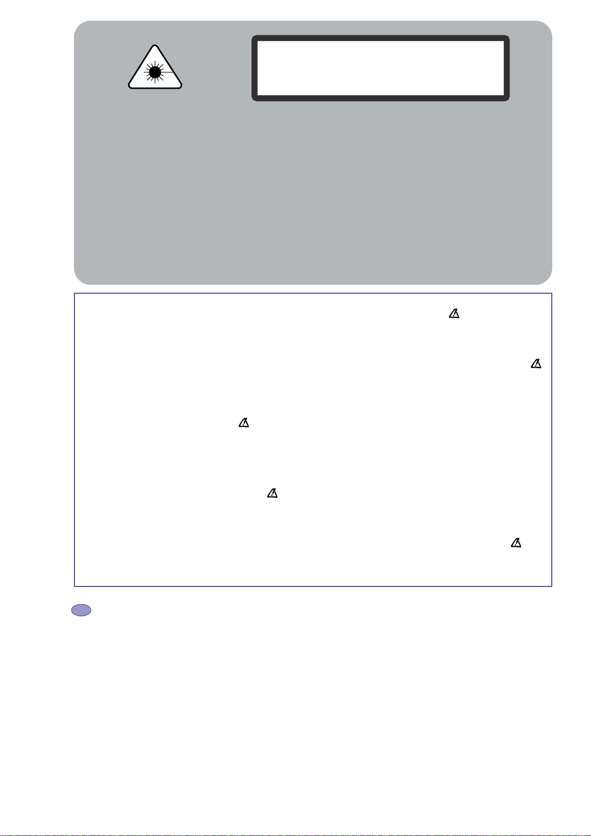
HANDLING THE OPTICAL PICKUP
The laser diode used in the optical pickup may
break down due to potential differences caused by
electricity produced by clothing or the human body,
care should therefore be taken to prevent
electrostatic discharge whilst repairing the optical
pickup.
The following method is recommended.
1) Place a conductive sheet on the work bench
(The black sheet used for wrapping repair
parts.)
2) Place the set on the conductive sheet so that
the chassis is grounded to the sheet.
3) Place your hands on the conductive sheet
(doing this gives them the same ground as the
sheet.
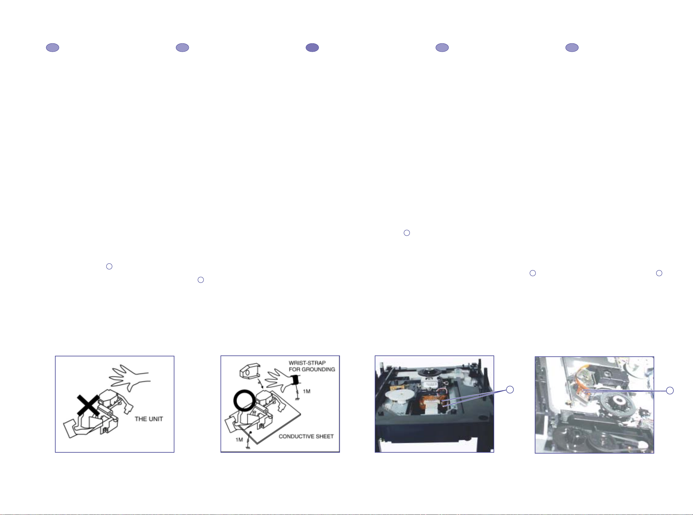
4) Remove the optical pickup block
5) Perform work on top of the conductive sheet. Be
careful not to let your clothes or any other static
sources to touch the unit.
* Grounding the Human Body, use an antistatic
wrist strap to discharge static electricity from
your body.
* Grounding the work place, use either an
antistatic matt or a sheet of steel on the area
where the optical pickup is to be placed and
ground the matt/sheet.
6) Short the short terminal on the PCB, which is
inside the Pickup Assembly, before
deconnecting the flexible cable for replacing the
Pickup. (The short terminal is shorted when the
Pickup Assembly is being lifted or moved.)
7) After replacing the Pickup, open the short
terminal on the PCB.
MANIPULATION DU BLOC OPTIQUE
La diode laser utilisée dans le bloc optique peut se
détériorer à cause d’une différence de potentiel
causé par l’électricité produite par les vêtements ou
le corps humain, par conséquent des précautions
doivent être prise pour éviter les décharges
électrostatiques pendant la réparation du bloc
optique.
Il est recommandé de suivre la méthode suivante.
1) Placez une feuille conductrice sur le banc de
travail (la feuille noire utilisée pour envelopper
les pièces détachées).
2) Placez l’ensemble sur la feuille conductrice pour
que le châssis soit mis à la masse par la feuille.
3) Mettez vos mains sur la feuille conductrice (en
faisant ceci, vous leur donnez la même masse
que la feuille)
4) Retirez le bloc optique
5) Travaillez en haut de la feuille conductrice.
Prenez soin de ne pas laisser vos vêtements ou
autre source statique toucher le bloc optique.
* Mise à la terre du corps humain : utilisez un
bracelet antistatique pour décharger l’électricité
statique de votre corps.
* Mise à la terre du poste de travail : placez soit
un tapis antistatique, soit
une feuille d’acier sur le banc de travail où vous
poserez le bloc optique après avoir relier le
tapis ou la feuille à la masse.
6) Pour remplacer le bloc optique, soudez le courtcircuit sur le circuit imprimé qui se trouve sur
l’ensemble optique, avant de déconnecter le
câble flexible (le court-circuit est soudé lorsque
l’ensemble optique est levé ou déplacé).
7) Après le remplacement du bloc optique,
dessoudez le court-circuit sur le circuit imprimé.
HANDHABUNG DER OPTISCHEN EINHEIT
Die verwendete Laser-Diode kann unter
Umständen zerstört werden, wenn sie mit statischer
Spannung aufgeladene Teile in Berührung kommt .
Deshalb ist unbedingt zu beachten, daß vor der
Reparatur alle Teile potentialfrei sind.
Empfehlenswert ist folgende Methode.
1) Eine leitende Unterlage auf den Werktisch
legen (über 1MOhm Widerstand geerdete
Leitgummi-Matte, Metallplatte oder ggf. die
schwarze Folie der Ersatzteilverpackung).
2) Das Gerät auf diese Fläche stellen, damit ein
Potenzialausgleich stattfinden kann.
3) Bringen Sie Ihren Körper auf das gleiche
Potenzial wie die Unterlage (z.B. mit
Handgelenkband über 1 MOhm geerdet).
4) Jetzt kann das DVD-Laufwerk bzw. die optische
Einheit ausgebaut werden .
5) Führen sie alle Arbeiten auf der LeitgummiMatte aus.
6) Zum Schutz des Lasers verbinden vor dem
Ausbau der optischen Einheit (Lösen der
Flachbandleitung) die beiden Lötpunkte auf
der Leiterplatte der optischen Einheit
miteinander. Die Leiterplatte befindet sich in der
optischen Einheit.
7) Nach dem Einbau der (neuen) optischen Einheit
den Kurzschluß wieder beseitigen !
MANEGGIAMENTO OTTICA PICKUP
Il diodo laser usato nelle ottiche pickup si può
danneggiare a causa di differenze di potenziale
causate da elettricità prodotta da vestiti o dal corpo
umano, particolari attenzioni devono essere prese,
durante la riparazione di apparecchiature con
pickup ottici, per prevenire scariche elettrostatiche.
Si raccomanda di seguire le seguenti indicazioni.
1) Mettere un foglio conduttivo sul banco di lavoro
(tipo foglio nero utilizzato per avvolgere le parti
di ricambio).
2) Posizionare l’apparecchiatura sul foglio
conduttivo per collegare la massa del telaio al
foglio conduttivo.
3) Toccare con le mani il foglio conduttivo per
avere lo stesso potenziale di massa del foglio
conduttivo.
4) Rimuovere l’assieme ottica pickup.
5) Lavorare sopra il foglio conduttivo. Evitare di far
toccare i propri vestiti o qualsiasi altra sorgente
statica all’apparecchiatura.
* Per scaricare a massa l’elettricità statica del
proprio corpo utilizzare l’apposito braccialetto
antistatico.
* Per mettere a terra il proprio posto di lavoro
utilizzare un tappetino antistatico o un foglio di
acciaio collegati a massa, sull’area dove deve
essere sostituita l’ottica.
6) In caso di sostituzione del pick up,
cortocircuitare prima gli appositi punti della
piastrina dell’assieme pickup, poi scollegare il
cavo di collegamento flessibile.
7) Aprire il cortocircuito dei terminali solo dopo la
sostituzione del Pickup.
MANEJO DEL CONJUNTO OPTICO
El diodo láser utilizado en el lector óptico puede
resultar averiado a causa de las diferencias de
potencial eléctrico producidas por el roce con la
ropa o con el cuerpo humano, también hay que
tener cuidado de que no se produzcan descargas
electrostáticas mientras se repara el lector óptico.
Se recomienda el siguiente método.
1) Colocar una hoja conductora en el banco de
trabajo (Vale la hoja negra que se utiliza para
envolver los repuestos).
2) Colocar el aparato en la hoja conductora de
forma que el chasis haga contacto con la hoja.
3) Poner las manos sobre la hoja conductora
(haciendo esto se da la misma toma de tierra
que a la hoja).
4) Retirar el conjunto óptico.
5) Realice el trabajo encima de la hoja conductora.
Tenga cuidado para no permitir que su ropa o
cualquier otra fuente de electricidad estática
pueda tocar a la unidad.
* Conecte a tierra el cuerpo humano, utilizando
una muñequera antiestática para descargar la
electricidad estática del cuerpo.
* Conectar a tierra el lugar de trabajo, utilizando
una alfombrilla antiestática o una hoja de papel
de aluminio en el área donde
se coloque el lector óptico y conectándola a la
toma de tierra.
6) Poner en cortocircuito los terminales de los
diodos (soldaduras en la cinta del conjunto
óptico) antes de desconectar el cable flexible
para remplazar el lector óptico.
7) Después de cambiar el lector óptico, quitar los
cortocircuitos anteriores.
version (A)
Fig. 1
Fig. 2 Fig. 3
Fig. 3 BIS
DBR105
First issue 06 / 03 7
8
Page 8
07
06
05
04
03
020107
06
05
04
03
02
01
07
06
05
04
03
02
01
07
06
05
04
03
02
01
07
06
05
04
03
02
01
06
05
07
04
version (A) version (A) version (A) version (A) version (A)
02
010301
EN FR DE IT ES
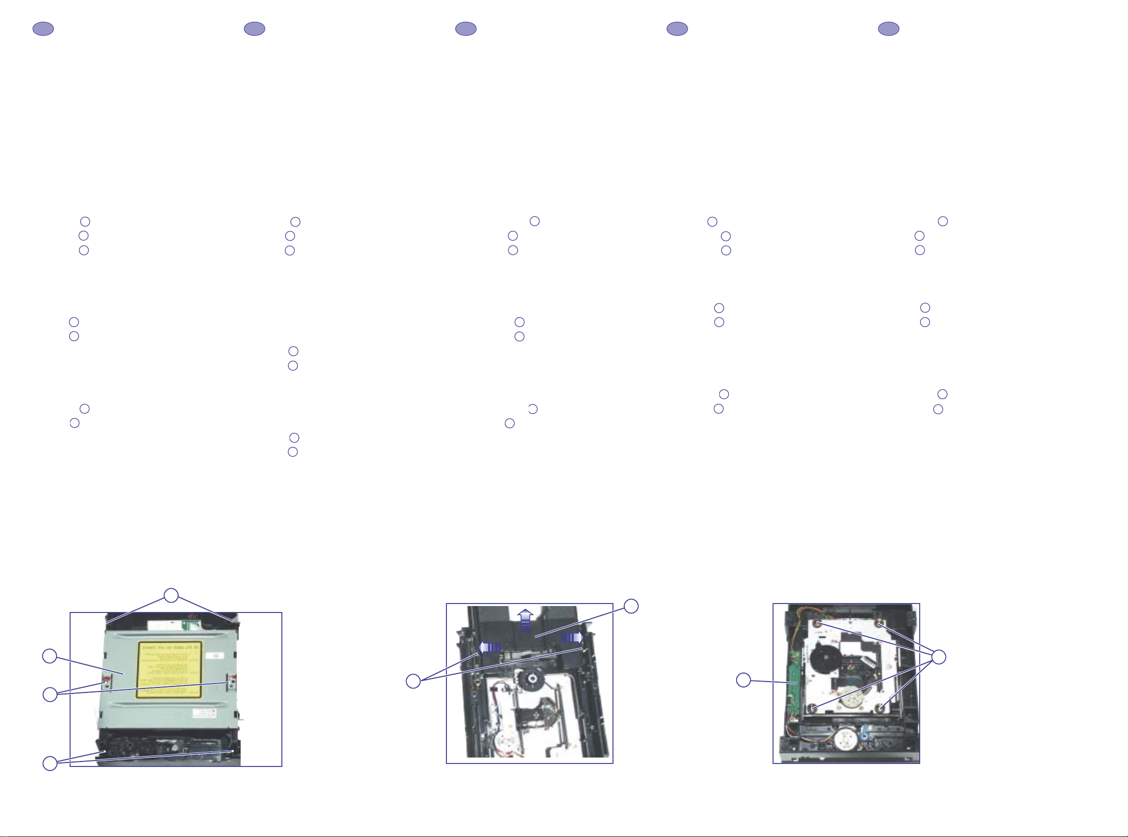
MECHANISM MAINTENANCE
In the following chapters, the reference marks of
spare parts indicate the dissassembling order. Unless
otherwise stated, reassemble in the reverse order.
REMOVAL / REFITTING
1- ACCESS TO DVD ASSEMBLY
Remove the 9 screws and the top cabinet.
2 - REMOVING THE DVD PLAYER
(fig. 1 and fig. 4)
Unscrew:
Remove:
Remove:
3 - REPLACING THE TRAY
(fig. 2 and fig. 4)
Push:
Push:
4 - REPLACING THE OPTICAL PICK-UP
(fig. 3)
Removal:
Unscrew:
Lift up:
MAINTENANCE DE LA MÉCANIQUE
Dans les chapitres suivants, le repérage des pièces
indique l'ordre de démontage. Sans indication
contraire, le remontage se fait dans l'ordre inverse.
DEMONTAGE / REMONTAGE
1 - ACCES À L'ENSEMBLE DVD
Retirer les 9 vis et le coffret supérieur.
2 - DÉPOSE DE L'ENSEMBLE DVD
(fig. 1)
Dévisser:
Retirer:
Retirer:
3 - REMPLACEMENT DU TIROIR
(fig. 2)
Pousser:
Pousser:
4 - REMPLACEMENT DU BLOC OPTIQUE
(fig. 3)
Démontage:
Dévisser:
Soulever
WARTUNG DES LAUFWERKS
In den folgenden Absätzen kennzeichnet die
Numerierung der Teile die Reihenfolge der
Demontage. Wenn nicht anders vermerkt, erfolgt
der Zusammenbau in umgekehrter Reihenfolge.
AUSBAU / EINBAU
1 - ZUGANG ZUM DVD-LAUFWERK
Entfernen Sie 9 Schrauben und den Gehäusedeckel
2-AUSBAU DES DVD-LAUFWERKES
(Abb.1)
Schrauben lösen:
Ausbauen:
Ausbauen:
3 - AUSTAUSCH DER SCHUBLADE
(Abb. 2)
Wegdrücken:
Wegdrücken:
4 - AUSTAUSCH DER OPTISCHEN EINHEIT
(Abb. 3 und Abb. 5)
Ausbau:
Schrauben lösen:
Heben sie:
MANUTENZIONE DELLA MECCANICA
I riferimenti delle parti di ricambio, indicati nei
seguenti capitoli, si riferiscono all’ordine di
smontaggio. Dove non specificato riassemblare in
ordine inverso.
SMONTAGGIO / RIMONTAGGIO
1 - ACCESSO ALL'ASSIEME DVD
Rimuovere le 9 viti e il coperchio.
2 - RIMOVUERE IL LETTORE DVD
(fig.1)
Svitare:
Rimuovere:
Rimuovere:
3 - SOSTITUZIONE DEL CASSETTO
(fig.2)
Spingere:
Spingere:
4 - SOSTITUZIONE DEL PICKUP
(fig. 3)
Smontaggio:
Scollegare:
Spingere:
.
MANTENIMIENTO DEL MECANISMO
En los siguientes epígrafes, las marcas de
referencia de repuestos indican el orden de
desensamblaje. A no ser que se diga otra cosa, el
reensamblaje es en el orden inverso.
DESMONTAJE / MONTAJE
1 - ACCESO AL CONJUNTO DVD
Retirar los 9 tornillos y la tapa superior.
2 - RETIRAR EL DVD
(fig.1)
Desatornillar:
Retirar:
Retirar:
3 - SUSTITUCION DE LA BANDEJA
(fig. 2)
Empujar:
Empujar:
4 - SUSTITUCION DEL CONJUNTO OPTICO
(fig. 3)
Desmontaje:
Desatornillar:
Hacia arriba:
Fig.1
Fig.2 Fig.3
DBR105
9
10 First issue 06 / 03
Page 9
11
10
09
0807060504
03
02
01
111009
080706
05
04
03
02
01
11
10
09
080706
05
04
03
02
01
11
10
09
080706
05
040302
01
11
10
09
080706
05
04
03
02
01
EN FR DE IT ES
02
11
03
06
04
10
07
05
09
01
06
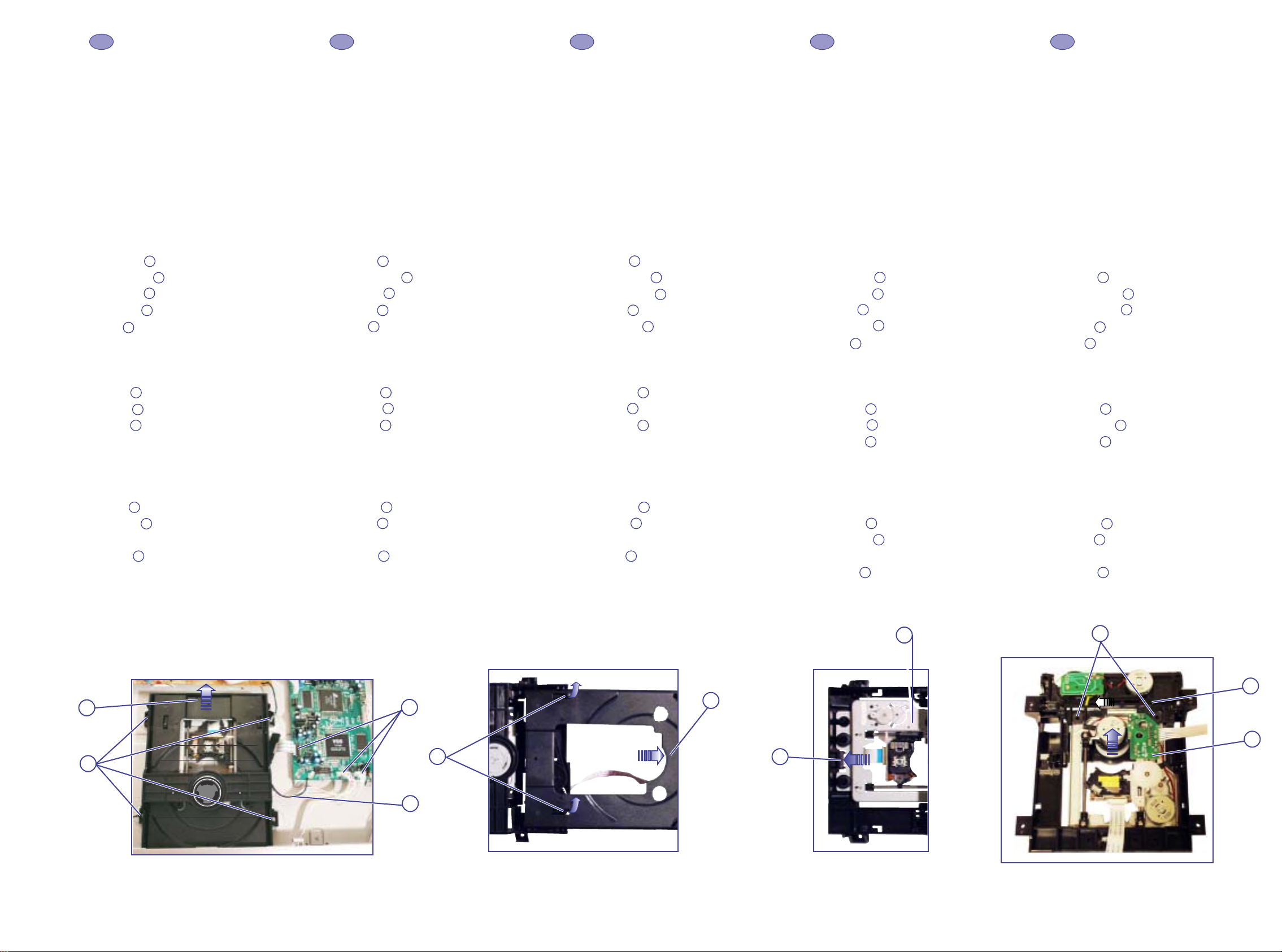
MECHANISM MAINTENANCE
In the following chapters, the reference marks of
spare parts indicate the dissassembling order. Unless
otherwise stated, reassemble in the reverse order.
REMOVAL / REFITTING
1- ACCESS TO DVD ASSEMBLY
Remove the 7 screws and the top cabinet.
2 - REMOVING THE DVD PLAYER
(fig. 1 and fig. 4)
Remove:
Disconnect:
Unscrew:
Remove:
Pull:
3 - REPLACING THE TRAY
(fig. 2 and fig. 4)
Push:
Lift up:
Push:
4 - REPLACING THE OPTICAL PICK-UP
(fig. 3 and fig. 4)
Removal:
Push:
Remove:
Refitting:
Insert:
Proceed in reverse order.
MAINTENANCE DE LA MÉCANIQUE
Dans les chapitres suivants, le repérage des pièces
indique l'ordre de démontage. Sans indication
contraire, le remontage se fait dans l'ordre inverse.
DEMONTAGE / REMONTAGE
1 - ACCES À L'ENSEMBLE DVD
Retirer les 7 vis et le coffret supérieur.
2 - DÉPOSE DE L'ENSEMBLE DVD
(fig. 1 et fig. 4)
Retirer:
Déconnecter:
Dévisser:
Retirer:
Tirer:
3 - REMPLACEMENT DU TIROIR
(fig. 2 et fig. 4)
Pousser:
Soulever:
Pousser:
4 - REMPLACEMENT DU BLOC OPTIQUE
(fig. 3 et fig. 4)
Démontage:
Pousser:
Retirer:
Remontage:
Insérer:
Procéder dans l'ordre inverse.
WARTUNG DES LAUFWERKS
In den folgenden Absätzen kennzeichnet die
Numerierung der Teile die Reihenfolge der
Demontage. Wenn nicht anders vermerkt, erfolgt
der Zusammenbau in umgekehrter Reihenfolge.
AUSBAU / EINBAU
1 - ZUGANG ZUM DVD-LAUFWERK
Entfernen Sie 7 Schrauben und den Gehäusedeckel
2-AUSBAU DES DVD-LAUFWERKES
(Abb.1 und Abb.4)
Ausbauen:
Verbinder lösen:
Schrauben lösen:
Ausbauen:
Herausziehen:
3 - AUSTAUSCH DER SCHUBLADE
(Abb. 2 und Abb. 4)
Wegdrücken:
Heben sie:
Wegdrücken:
4 - AUSTAUSCH DER OPTISCHEN EINHEIT
(Abb. 3 und Abb. 5)
Ausbau:
Wegdrücken:
Ausbauen:
Einbau:
Einfügen:
Der Zusammenbau erfolgt in umgekehrter
Reihenfolge.
MANUTENZIONE DELLA MECCANICA
I riferimenti delle parti di ricambio, indicati nei
seguenti capitoli, si riferiscono all’ordine di
smontaggio. Dove non specificato riassemblare in
ordine inverso.
SMONTAGGIO / RIMONTAGGIO
1 - ACCESSO ALL'ASSIEME DVD
Rimuovere le 7 viti e il coperchio.
2 - RIMOVUERE IL LETTORE DVD
(fig.1 e fig.4)
Rimuovere :
Scollegare:
Svitare:
Rimuovere:
Tirare:
3 - SOSTITUZIONE DEL CASSETTO
(fig.2 e fig. 4)
Spingere:
Sollevare:
Spingere:
4 - SOSTITUZIONE DEL PICKUP
(fig. 3 e fig. 4)
Smontaggio:
Spingere:
Rimuovere:
Rimontaggio:
Inserire:
Procedere seguendo l'ordine inverso.
MANTENIMIENTO DEL MECANISMO
En los siguientes epígrafes, las marcas de
referencia de repuestos indican el orden de
desensamblaje. A no ser que se diga otra cosa, el
reensamblaje es en el orden inverso.
DESMONTAJE / MONTAJE
1 - ACCESO AL CONJUNTO DVD
Retirar los 7 tornillos y la tapa superior.
2 - RETIRAR EL DVD
(fig.1 y fig. 4)
Retirar :
Desconnectar:
Desatornillar:
Retirar:
Tirar:
3 - SUSTITUCION DE LA BANDEJA
(fig. 2 y fig. 4)
Empujar:
Hacia arriba:
Empujar:
4 - SUSTITUCION DEL CONJUNTO OPTICO
(fig. 3 y fig. 4)
Desmontaje:
Empujar:
Retirar:
Montaje:
Insertar:
Proceder en orden inverso.
Fig.1
DBR105
First issue 06 / 03 11
Fig.2 Fig.3
Fig.4
12
Page 10
LN
Housing
Solder
Header
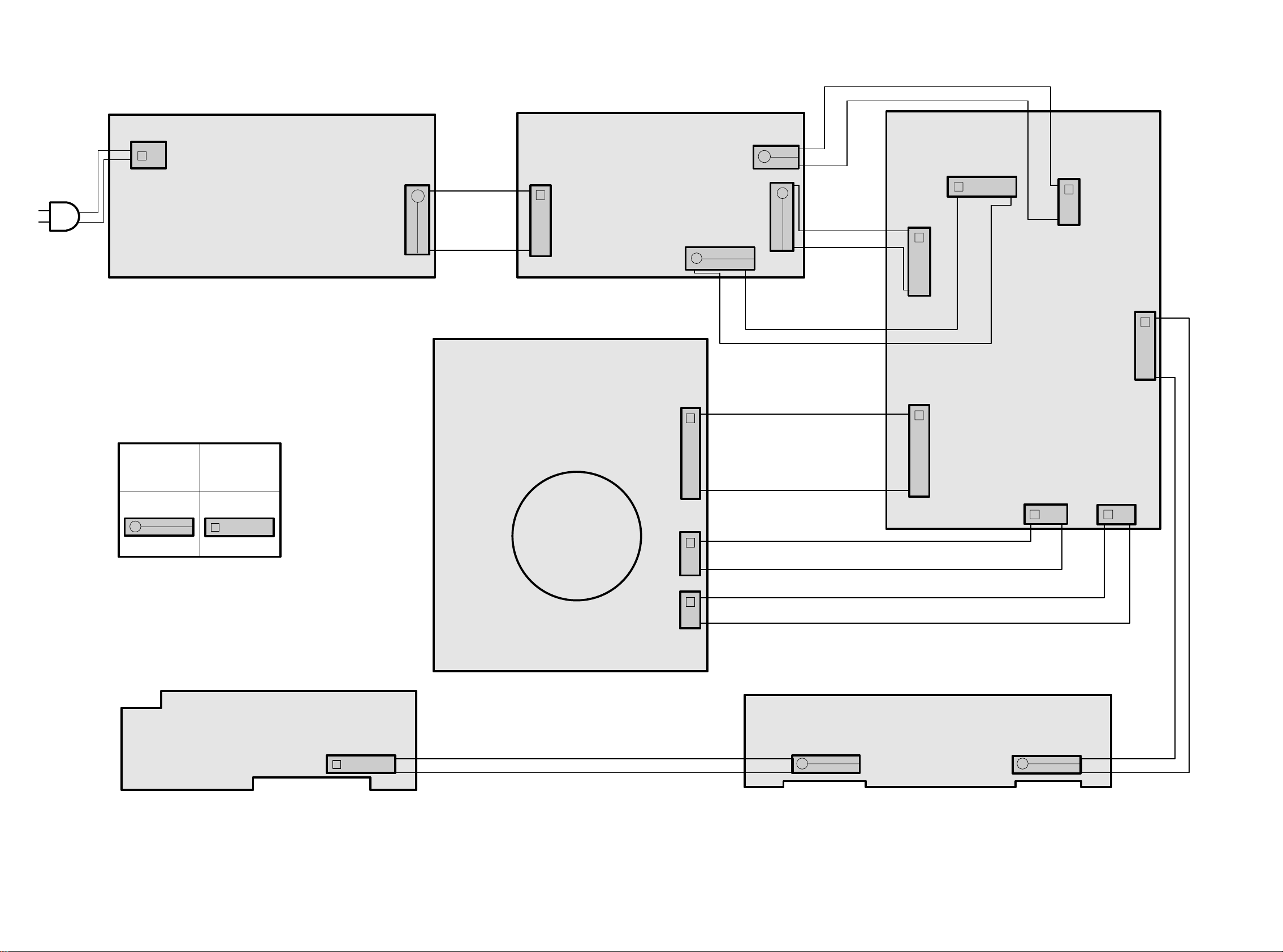
Wiring diagram of DBR 105EA
PSU BD
FRONT PANEL BD
SINGLE SCART BD
MAIN BD
V17.X
DVD34
LOADER
55-2113027-10-01 55-2120267-19-02
55-2120014-20-05
J806
JS1
JS5
JS3
JS2
J801
CN3
CN4
CN5
CN2
SCN2 SCN3
24 Pins
6 Pins
5 Pins
8 Pins
JP3
55-2105157-19-10
SWITCH BD
JP2
55-2105037-19-10
JP1
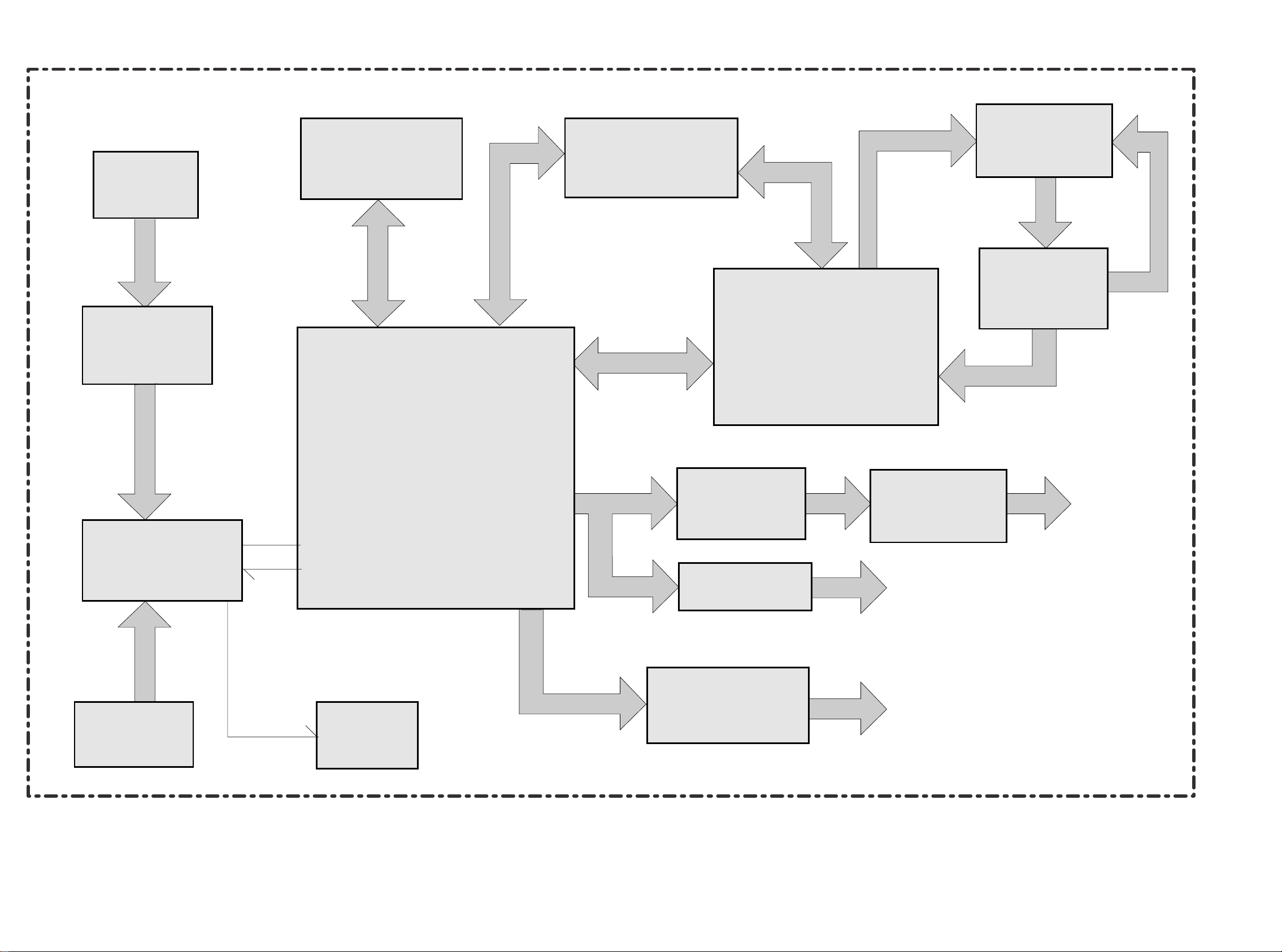
GENERAL BLOCK DIAGRAM - SYNOPTIQUE GÉNÉRAL - BLOCKSCHALTBILD ALLGEMEIN - SCHEMA A BLOCCHI GENERALE - ESQUEMA DE BLOQUES GENERAL
version (A)
13
DBR105
14 First issue 06 / 03
Page 11
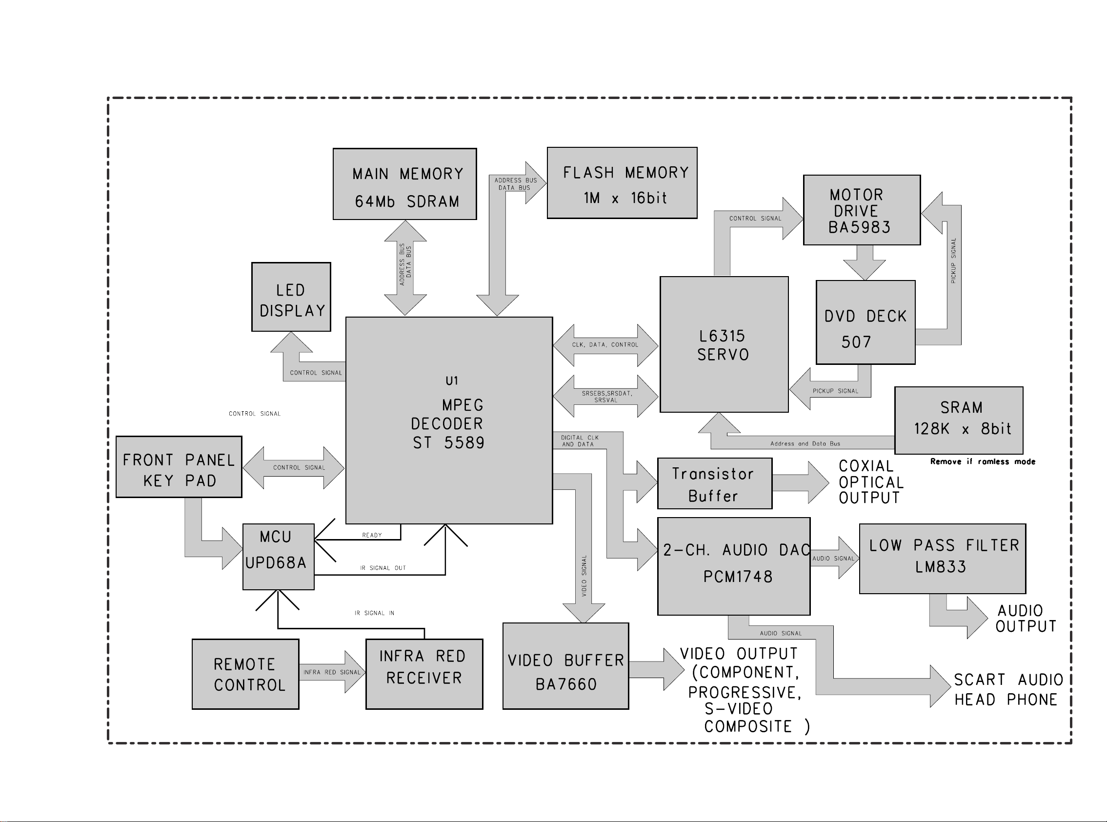
BLOCK DIAGRAM - SCHEMA SYNOPTIQUE - BLOCKSCHALTBILD - SCHEMA A BLOCCHI - ESQUEMA DE BLOQUES
DBR105
First issue 06 / 03 15
16
Page 12
REMOTE
CONTROL
64Mb SDRAM
MAIN MEMORY
1M X 8bit
FLASH MEMORY
MOTOR DRIVER
BA5954FP
DVD DECK
DV34
VT7206
SERVO
U1
AML3300
MPEG DECODER
AUDIO DAC
PCM1748
LED
DISPLAY
FRONT PANEL
KEY PAD
LPF LM833
2 CH
AUDIO
OUTPUT
COAXIAL
OUTPUT
VIDEO OUTPUT
( COMPOSITE & SCART )
VIDEO OUT
LPF
74HC14
MCU
UPD68A
INFRA RED
RECEIVER
ADRESS BUS
DATA BUS
ADRESS BUS
DATA BUS
ADRESS BUS
DATA BUS
ATAPI INTERFACE
CONTROL SIGNAL
PICKUP SIGNAL
PICKUP SIGNAL
AUDIO SIGNALAUDIO SIGNAL
IR SIGNAL
CONTROL SIGNAL
IR SIGNAL
READY
INFRA RED SIGNAL
VIDEO SIGNAL
DIGITAL DATA
DBR105E (A) BLOCK DIAGRAM
BLOCK DIAGRAM - SCHEMA SYNOPTIQUE - BLOCKSCHALTBILD - SCHEMA A BLOCCHI - ESQUEMA DE BLOQUES
17
18 First issue 06 / 03
DBR105
Page 13
BLOCK DIAGRAM OF DXX105N/E
BLOCK DIAGRAM - SCHEMA SYNOPTIQUE - BLOCKSCHALTBILD - SCHEMA A BLOCCHI - ESQUEMA DE BLOQUES
DBR105
First issue 06 / 03 19
20
Page 14
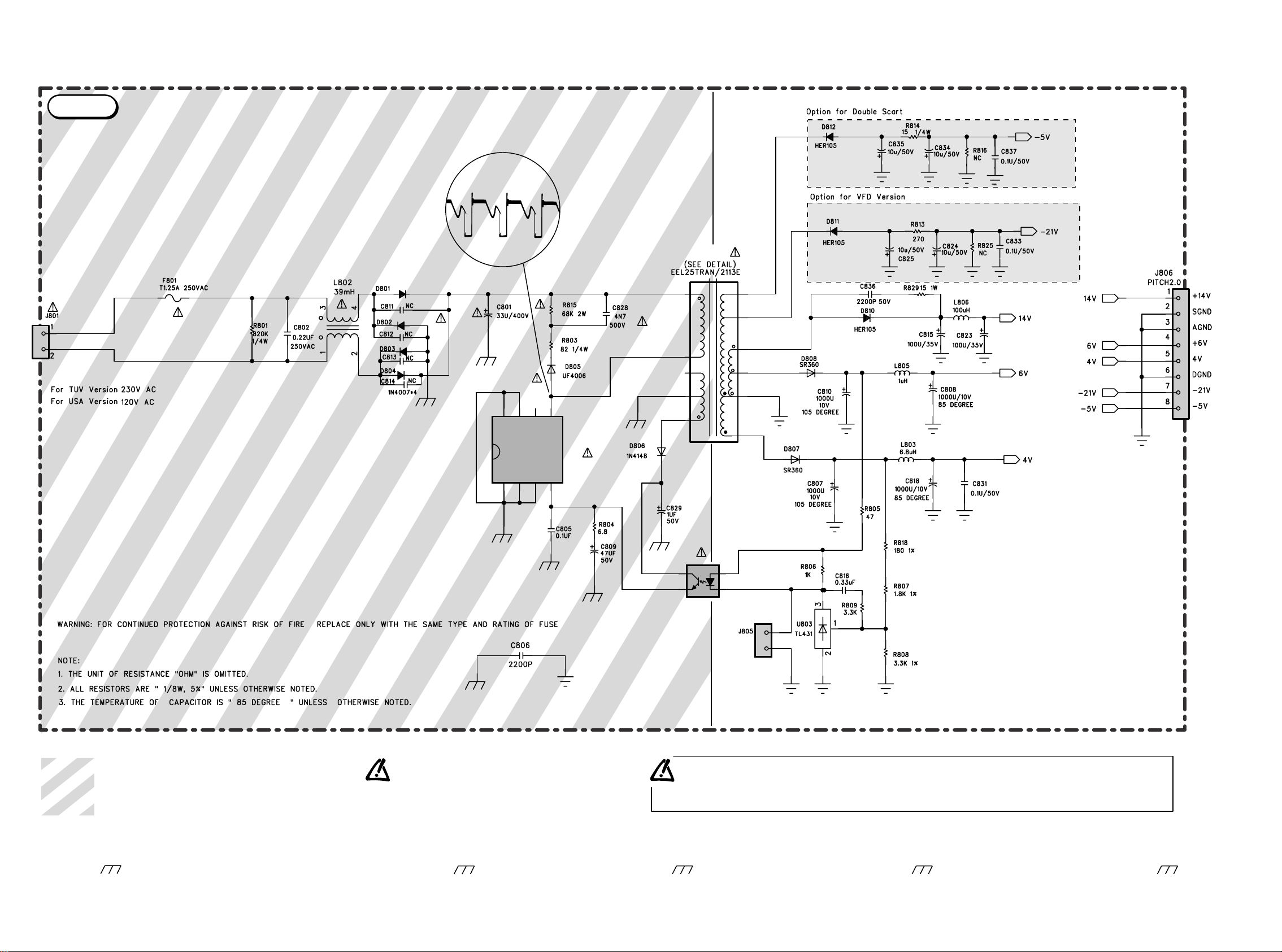
Achtung :
Bei Messungen im Primärnetzteil
- Primärnetzteilmasse verwenden ( ).
Note :
Power Supply primary circuit measurements.
- Use only ( ) connection point.
Attention :
Mesure dans la partie primaire de l'alimentation
- Utiliser la masse du bloc alimentation ( ).
Attenzione :
misure nell'alimentatore primario
- usare massa alimentazione primario ( ).
Cuidado :
Medida en el bloque de alimentacion
- Utilizar la masa del bloque de alimentacion ( ).
Part of board connected to mains supply.
Partie du châssis reliée au secteur.
Primärseite des Netzteils.
Parte dello châssis collegata alla rete.
Parte del chassis conectar a la red.
Use isolating mains transformer.
Utiliser un transformateur isolateur du secteur.
Einen Trenntrafo verwenden.
Utilizar un transformador aislador de red.
Utilizzare un transformatore per isolarvi dalla rete.
Safety Part
When repairing, use original part only
Pièce de securité
N'utilisez que les pièces d'origine
Utilice solo piezas originales
Bei Ersatz nur Originalteil verwenden
Sicherheitsbauteil
Pieza de seguridad
Per la riparazione utilizzare solo componenti originali
Componenti di sicurezza
55-2113027-10-01
DVD2120P PSU BD VER.13.01
1
4
5
6
4
3
1
2
1
2
1
M
S1S2C
S4
S3
D
234
7
14
12
13
11
10
8
87 65
U801
TOP243P
U802
PC817A
T801
POWER
7µs
500Vpp
306V
POWER SUPPLY SCHEMATIC DIAGRAM - SCHEMA DES CIRCUITS D’ALIMENTATIONS - SCHALTBILD NETZTEIL - SCHEMA DEI CIRCUITI DI ALIMENTAZIONE
ESQUEMA DE LOS CIRCUITOS DE ALIMENTACIÓN
version (A)
21
22 First issue 06 / 03
DBR105
Page 15

DBR105
First issue 06 / 03 23
VOLTAGE INFORMATION
PIN NO. DVD PB EE CD PB PIN NO. DVD PB EE CD PB PIN NO. DVD PB EE CD PB
1 1.66 0.13 1.72 52 0.85 0 0.84 125 3.28 3.29 3.28
2 3.35 3.37 3.35
CNCNC
CNCNC
53, 54 0.01 0 0.01 126, 127 NC NC NC
55, 56, 57 1.69 1.69 1.69 128 to130 3.37
00 0
00 0
00 0
00 0
00 0
00 0
00 0
000
000
000
000
000
000
3.37 3.37
4 3.37 3.4 3.37 58 to 63 Add. BusAdd. Bus Add. Bus
131
5642.47 2.47 2.47 132 2.11 2.62 2.6
6, 7, 65 133 , 134 NC NC NC
9 1.63 1.65 1.63 66 to 73 Add Bus Add Bus Add Bus 135 3.31 3.37 3.31
10 4.48 4.52 4.49 74 2.51 2.54 2.53 136 3.37 3.37 3.37
11 1.64 1.65 1.64 75 2.8 2.63 2.73
137
12 NC NC NC 76 2.3 3.32 2.97 138 NC NC NC
13 1.67 1.9 1.74 77 3.1 3.04 3.04 139 3.31 3.35 3.31
14 2.47 2.5 2.47 78 3.11 3.34 2.77 140 3.37 3.37 3.37
15 79 0.02 0.01 0.13
141to148 Data Bus Data Bus Data Bus
16 1.3 0.03 0.23 80 0.02 0.01 0.12 149 2.46 2.46 2.46
17 1.62 1.65 1.63 81 3.37 3.37 3.37
150
18 1.74 0.03 0.35 82 1.53 1.71 1.57 151to158 Data Bus Data Bus Data Bus
19 0.01 0.03 0.01 83 159 3.37 3.37 3.37
20 to 22 NC NC NC 84 to 93 Data Bus Data Bus Data Bus
160
23 2.46 2.49 2.46 94 2.47 2.47 2.47 161to170 Add. Bus Add. Bus Add. Bus
24 95 1.63 1.69 1.53 171 2.45 2.45 2.45
25 0.57 0.61 0.59 96 172
26 0.53 0.93 0.91 97 to 102 Data Bus Data Bus Data Bus 173to183 Add. Bus Add. Bus Add. Bus
27 0.61 0.61 0.59 103 2.13 1.93 2.01 184 3.37 3.38 3.37
28 104 2.16 1.98 2.02 185
29 1.26 1.28 1.26 105 2.16 1.94 2 186to188 NC NC NC
30 2.46 2.48 2.46 106 1.64 1.62 1.6 189 4.43 4.63 4.56
31 107 3.37 3.38 3.37 190 4.61 4.63 4.61
32 0.66 0.92 0.89 108, 109 191 4.48 4.63 4.52
33 0.59 0.62 0.59 110 3.37 3.37 3.37 192 4.33 4.63 4.52
34 0.66 0.91 0.89 111 1.18 1.42 0.84 193 NC NC NC
35 112, 113 3.37 3.37 3.37 194,195 3.31 3.36 3.34
36 1.27 1.29 1.27 114 NC NC NC 196 NC NC NC
37 2.48 2.5 2.48 115 0.02 0.02 0.02 197 1.86 2.2 1.73
38 to 40 116 NC NC NC 198 2.45 2.46 2.45
41 3.37 3.4 3.37 117 2.2 2.7 2.7 199
42 3.37 3.39 3.37 118 1.7 1.69 1.69 200,201 0.01 0.01 0.01
43 3.37 2.28 3.37 119 2.46 2.46 2.46 202 0.87 1.2 0.22
44 to 46 NC NC NC 120 1.64 1.63 1.65 203 0.01 0.01 0.01
47 3.37 3.4 3.37 121 204 NC NC NC
48 2.46 2.48 2.46 122 2.41 2.41 2.41 205, 206 0.01 0.01 0.01
49, 50 123 207, 208 NC NC NC
51 1.69 1.68 1.69 124 3.37 3.37 3.37
PIN NO. DVD PB EE CD PB PIN NO. DVD PB EE CD PB PIN NO. DVD PB EE CD PB
1 2.23 0 2.23 1 Data Bus 0 Data Bus
1,3,5,8
2,6,9,10 NC NC NC 2 Data Bus 0 Data Bus 2,4,7
video signal
0
0
video signal
3 2.23 0 2.23 3 Data Bus 0 Data Bus 6,11 NC NC
4 2.23 0 2.23 4 Data Bus 0 Data Bus 9 2.14 0 2.14
5,7,8,11 5 Data Bus 0 Data Bus 10 2.22 0 2.22
12 2.23 0 2.23 6 3.46 0 3.46 12 2.06 0 2.06
13 1.96 0 1.96 7 Data Bus 0 Data Bus 13 2.13 0 2.13
14 3.44 0 3.44 8
9
3.46 0
0
3.46 14 1.6 0 1.6
NCNC
15 1.64 0 1.64
10-20 Add.Bus 0 Add.Bus 16
21-23 I/O 0 I/O
PIN NO. DVD PB EE CD PB
24
ICL 5 (LM358)
1 5.61 5.6 5.62 25-29 I/O 0 I/O PIN NO. DVD PB EE CD PB
2 5.61 5.6 5.62
30
1 2.4 0 2.4
3 5.61 5.6 5.62 31 Data Bus 0 Data Bus 2 2.2 0 2.2
432Data Bus 0 Data Bus 3 2.2 0 2.2
5 5.61 5.6 5.62
4
6 5.62 5.6 5.62 5 0.4 0 0.4
7 5.63 5.61 5.63 6 0.4 0 0.4
8 11.22 11.19 11.24 7 1.7 0 1.6
8
ICV 1/2 (BA7660F S)
000
000
000
000
000
000
000
000
000
000
000
000
000
505
000
505
MAIN BD
ICS 1(STi5589)
ICS 3 (74HCU04)
ICL 3 (AMIC A62S7308A )
ICA3(LM833)
Page 16

DBR105
24 First issue 06 / 03
VOLTAGE INFORMATION
ALM3300(U1)
PINNO DVD PB
CD PB
STOP PINNO DVD PB
CD PB
STOP
0.003 0.003 70 0.18 3.28 1.436 139 3.27 0.026 3.275
0.087 0.091 71 0.16 3.28 1.211 140 3.2 3.255 3.278
4.857 2.168 72 1.7 1.395 1.122 141 3.2 3.279 3.276
4
10
0
0
5
1
2
3
5
8
1.452 4.859 4.17 73 1.6 1.557 1.399 142 3.27 3.253 11
4.516 4.992 74 1.8 1.587 1.274 143 1.2 0.966 2.611
6 0.2 0.249 0.17 75 1.58 0.511 0.959 144 1.3 1.167 2.677
7 0.2 0.17 0.172 76 0 0.005 0.005 145 1.54 1.297 2.69
0 0.482 77 1.8 1.769 1.734 146 0 1.439 0.003
9 4.7 2.189 2.179 78 0.15 0.05 0.143 147 1.65 0.003 0.013
10 1.6 1.653 1.655 79 0.003 148 1.61 1.665 1.666
11 1.72 1.686 0.109 80 1.66 1.66 1.668 149 1 1.614 1.666
12 0 0.015 0.019 81 0.03 0.024 0.147 150 1 1.078 0.013
13 0.1 0.105 0.109 82 0.027 0.009 0.143 151 0 1.07 0.019
14 1.4 1.597 0.019 83 1.19 0.053 1.039 152 2.3 1.303 2.376
15 1.6 1.639 1.642 84 1.27 0.039 1.041 153 0 2.264 0.003
16 2.1 1.931 1.923 85 1.2 0.027 0.345 154 3.2 0.003 3.278
17 0 0.003 0.003 86 0 0.041 0.003 155 2.05 2.05 1.8
18 1.6 1.666 1.669 87 3.27 3.27 3.277 156 4.94 4.94 4.94
19 1.66 1.686 1.668 88 3 3.2 0.349 157 1.65 1.65 1.65
20 0 0.003 0.003 89 3.2 3.2 3.2 158 0 0.002 0.003
21 0.59 0.986 0.469 90 3.2 3.204 3.143 159 0 0.003 0.003
22 3.1 3.11 3.109 91 3.2 3.2 3.115 160 1.67 1.665 1.667
23 0 0.004 0.003 92 3.1 0.041 32.964 161 1.65 1.662 1.663
24 2.7 2.717 0.003 93 0.18 0.18 1.647 162 0 0.003 0.003
25 3 3.111 3.11 94 0 0.048 2.206 163 1.65 1.665 0.021
26 0 0.004 0.003 95 0 0.023 0.013 164 1.65 1.662 0.012
27 0 3.252 2.588 96 0.016 0.04 0.02 165 0 0.003 0.003
28 0 3.237 3.109 97 0.016 148 0.022 166 1.65 1.665 0.015
29 0 0.003 0.003 98 0.2 0.337 0.214 167 3.7 3.776 0.011
30 0 2.046 2.045 99 0.2 2.853 0.217 168 0 0.045 0.002
31 0 1.254 1.894 100 3.27 0.05 3.277 169 4.598 4.589 4.992
32 1.28 1.26 1.261 101 0 0.062 0.006 170 5 4.993 4.997
33 1.28 1.26 1.261 102 0 0.102 0.002 171 2.9 2.916 0.016
34 0 0.003 0.003 103 0 0.1 3.279 172 3.2 3.285 3.227
35 3 3.108 3.109 104 0
00
00
0.032 0.002 173 3.2 3.268 0.02
36 3.1 3.1
00
00
3.108 105 1.667 174 0 0.003 0.002
37 0.002 106 0 1.775 1.795 175 3.26 3.192 3.272
38 1.25 1.272 1.273 107 0.004 176 3.26 3.265 3.271
39 1.25 1.28 1.273 108 0 0.004 0.003 177 3.2 3.244 3.275
40 1.24 1.258 1.259 109 0 0.026 0.004 178 3.2 3.286 3.272
41 2 2.055 2.056 110 3.27 3.27 3.275 179 3.2 3.171 3.272
42 0 0.003 0.003 111 3.2 3.251 3.229 180 1.24
43 0 3.136 3.107 112 3.2 3.251 3.229 181 1.65 1.689 1.685
44 0.4 0.703 0.703 113 1.76 3.266 0.009 182 1.68 0.003 1.795
45 0 0.003 0.003 114 0 0.022 3.276 183 0 0.003 0
46 3.1 3.1 3.105 115 2.3 3.299 3.276 184 0 0.002 0.002
47 0.66 0 0.442 116 2.279 2.279 2.363 185 3.2 3.274 0.002
48 0 0.003 0.003 117 2.3 2.262 2.354 186 1.66 1.669 0
49 3.1 3.103 3.105 118 0 2.26 3.277 187 5 4.76 0.018
50 0 0.561 0.564 119 2.3 2.759 2.347 188 5 4.756 4.992
51 0 0.003 0.002 120 0 2.256 0.002 189 1 0.003 0.018
52 1.66 1.672 0.003 121 3.27 0.003 3.278 190 3.2 3.277 0.003
53 2.67 1.53 1.547 122 2.3 3.281 2.364 191 3.2 4.736 0
54 1.64 1.64 1.643 123 0 2.248 0.048 192 4.5 4.742 0
55 1.5 1.35 1.081 124 3.27 0.014 0.075 193 4.8 4.896 0
56 1.5 1.585 1.368 125 0 3.279 3.277 194 4.5 4.896 0
57 1.5 1.534 1.249 126 1.66 0.003 0.003 195 4.5 4.896 4.992
58 1.57 1.536 1.197 127 0 1.666 1.666 196 4.5 4.893 0
59 1.65 1.381 1.12 128 0 0.024 1.666 197 4.9 4.856 0
60 1.32 1.051 0.716 129 0 0.03 0.049 198 4.8 4.896 0
61 0 3.6 0.003 130 0 3.253 0.029 199 4.5 4.896 4.993
62 3.27 3.28 3.279 131 3.2 0.033 3.275 200 4.5 4.896 0
63 1 2.375 6.894 132 0 3.255 0.024 201 4.5 4.896 0
64 2 4.65 0.446 133 0 0.011 0.024 202 0 4.76 4.993
65 0 0.004 0.004 134 3.25 0.024 0.05 203 0 4.894 0
66 1.6 0.031 1.67 135 3.25 3.285 3.258 204 0 4.896 0.012
67 0 0.303 0.004 136 0 3.252 0.002 205 0 3.274 0
68 0.1 0.24 1.079 137 3.27 0.003 3.277 206 0 3.273 0
69 0.18 3.28 1.437 138 0 3.28 0.031 207 3.2 3.285 3.284
208 1.67 1.669 1.669
00
PINNO DVD PB
CD PB
STOP
Page 17

DBR105
First issue 06 / 03 25
VOLTAGE INFORMATION
MAIN BOARD
VT7206(SU1)
PIN NO. DVD PB CD PB STOP PIN NO. DVD PB CD PB STOP PIN NO. DVD PB CD PB STOP
1 0.004
20
0.004 0.003 64 1.45 1.44 1.481 127 4.8 4.881 4.881
0.143 0.003 65 0 1.578 1.578 128 3.25 0 0.995
3 0.004 0.004 0.003 66 129 4.8 0 1.04
4 4.5 1.388 4.386 67 1.24 130 0.12 0.002 0.962
5 1.14 4.481 4.432 68 1.5 1.792 1.792 131 4.8 4.945 4.993
6 3.2 3.248 3.256 69 132 4.8 4.881 4.993
7 0.8 0.143 0.003 70 0 1.098 1.098 133 4.8 4.881 4.993
8 0.004 0.052 0.003 71 0 3.261 3.261 134 2.15 2.464 2.463
9 1.03 0.997 3.247 72 0.78 0.866 0.866 135 0.02 0.004 0.003
10 1.7 0.043 1.684 73 3.2 3.255 3.255 136 0 0.003 0.002
11 1.7 0.054 1.684 74 0 0.002 0.002 137 2.45 0 0.003
12 3.2 3.247 3.254 75 0 3.117 3.117 138 4.8 0 4.993
13 1.55 1.54 1.915 76 0 3.258 3.196 139 4.8 4.881 4.993
14 1.57 1.56 1.185 77 2.5 2.456 2.462 140 4.73 4.883 0.014
15 0.004 0.004 0.003
0
0
0
0
0
78 3.25 3.255 3.196
141 0.48
16 1.48 1.451 79 0.003 0.002 0.002 142 0 0.124 0
17 1.47 0.053 80 3.25 3.26 3.262 143 3.2 3.281 3.285
18 1.924 1.924 3.819 2.467 144 3.2 3.245 3.293
19 1.43 1.314 3.2 3.174 3.263 145 0.9 1.031 0.549
20 1.3 1.22 1.173 1.098 146 0 0.003 0.002
21 0 1.378 3.254 84
83
82
81
0
0
0
0.002 0.001 147 3.25 3.159 0.017
22 0 3.247 0.003 85 0 2.508 0.64 148 0.006 0 0.002
23 0 0.004 3.253 86 0 0.002 0.681 149 0.17 0.169 0
24 3.2 3.247 3.247 87 3.25 3.28 2.58 150 0.04 2.699 0.023
25 0 1.475 1.481 88 0.003 0.002 0.002 151 0 0.171 0.176
26 0 1.477 0.007 89 0.018 0 0.017 152 0.06 3.282 3.285
27 0 1.528 1.484 90 0 0.002 0.002 153 0.07 3.27 3.27
28 0 2.005 91 3.24 0.002 0.002 154 0.07 3.271 0
29 0 1.482 1.48 92 0.004 0 0.566
155 0.05
30 1.5 1.483 1.482 93 0.026 0.002 0.599 156 0.02 0 0.002
31 0.004 0.003 2.46 94 0
0
0
00
00
0.052 0.051 157 3.254 0 3.262
32 0.16 2.461 95 3.2 0 3.262
158 0.509
33 0 0.003 1.635 96
97
98
0.03 0.006 0.002 159 1.03 1 0.97
34 0 1.632 0.003 0.002 160 0.03 0.003 0.026
35 0 3.256 0.002 0.004 161 1.32 1.453 0.788
36 0 2.462 99 2.18 3.124 0.585 162 0 1.583 0
37 0 0.004 0 100 0 0.002 0.002 163 0.04 1.569 0
38 0
00
00
00
00
00
00
2.462 0 101 0 0.002 0.002 164 0.03 1.521 1.511
39 0.004 0.004 0 102 0.03 3.839 2.574 165 3.25 0 3.258
40 1.5 0.732 0 103 0.351 166 0.04 2.132 0.015
41 0 1.246 2.809 104 0 3.798 3.798 167 0.03 2.133 0
42 0.505
105 0 2.591 2.591
168 0.019
43 3.263
106 0.002 169 0.03 1.47 0
44 0 1.477 0.671 107 1.64 1.641 1.642
170 3.258
45 0 3.285 3.262 108 171 0.047
46 0.002 0.002 3.262 109 0.07 1.641 1.641
172 1.3
47 2.117
110 0.09 3.259 3.263 173
48 3.2 0.824 0 111 0 0.03 0.773
174
49 1.5 1.855 0 112 175 1.7
50 0 1.984 0 113 0 0.087 0.092 176 0 1.687 0
51 0 0.458 1.86 114 4.97 4.977 4.965
177 1.7
52 0 1.764 1.674 115 0 4.879 4.967 178 1.7 1.687 0
53 1.934
116 0 4.881 4.966
179 1.514
54 1.12
117 0 3.259 3.263 180 1.62 0 0.014
55 0 1.372 1.1 118 4.5 0 0.926
181 3.24
56 0 3.293 1.397 119 0 0.002 0.002 182 0.04 2.133 0
57 3.2 3.261 3.263 120 0.04 183 1.25 1.116 0
58 0 0.07 1.491 121 0 4.881 4.881
184 2.14
59 0.6 1.305 0.863 122 185 1.28 1.025 0
60 0 0.002 0.001 123 2.45 2.463 2.463
186 1.52
61 0.98 0 1.033 124 4.8 4.881 4.881
187 0.02
62 1.3 1.304 1.282 125 0.004 0.003 0.003 188 0.055 0.004 0
63 1.076
126 4.8 4.881 4.881
189 2.14
0
0
0
0
0
00 0
00 0
00 0
00
00 0
00 0
00
00
00
00
00
00
00
00
00
00
00
00
00
00
000
000
00
00
Page 18

DBR105
26 First issue 06 / 03
VOLTAGE INFORMATION
PIN NO. DVD PB CD PB STOP
LM393(SU3) TOP243P(U801)
190 0 1.481 0
00
00
00
0
00
0
0
0
0
000
000
000
PIN NO. DVD PB CD PB STOP
PIN NO. DVD PB CD PB STOP
191 1.306 1.298 0.014 1 0.05 0.053 0.052 1
192 3.24 3.25 3.256 2 1.004 1.04 0.001 2
193 1.692 3
4
2.354 0
0
0
0.001 3
4
194 1.7 0.001 5.81 5.81 5.81
195 1.7 5
6
0.003 1.004 0.551 5 327.5 325.4 312.7
196 1.7 1.687 0.003 10.37 0.58 NCNCNC6
197 0 1.687 1.687 7
8
0.003 1.049 0.594 7
198 1.7 0.035 5.969 4.96 4.998 8
199 0 0.004 0
0
200 0.03
201 0.02 1.6 1.107 BA5954(SU2) SN74HC14(U3)
202 0.58
PIN NO. DVD PB CD PB STOP PIN NO. DVD PB CD PB STOP
203 1.26 1.13
1.5 1.52 1.482
1 0.004 0.003 0.002
204 0 3.248
2.47 2.394 2.488
2 4.98 4.993 4.998
205
3
2
1
2.47 2.364 0.473
3 2.527 2.527 2.522
206
4 1.48 1.481 1.48
4 2.456 2.465 2.478
207
5 1.5 1.482 1.481
5 1.644 1.644 1.643
208 0 2.334 1.05
6 1.5 1.509 1.479
6
7
2.52 2.527 2.521
7 2.47 2.292 0.411
0.003 0
8 7.898 7.898 7.916
8 2.47 2.466 2.477
PCM1748(U10)
VT7206 (SU1)
9 4.958 4.958 4.998
9 2.52 2.527 2.522
PIN NO. DVD PB CD PB STOP
10 0 0.045
10 4.997 4.997 4.977
1 1.64 1.648 1.65
11 3.89 3.89 2.336
11 0.004 0.003 0.002
2 1.6 1.06 0.013
12 4.01 3.933 2.334
12 4.99 4.99 4.998
3 1.63 1.638 1.637
13 0.05 2.26 0.342
13 0
0
0.003 0.002
4
14 2.5 0 0.347
14 5 4.998 5
5 3.75 3.7 3.75
15 2.46 0.028 0.355
6 5.13 5.13 5.13
16 2.5 2.47 0.348
LM833D(U8,U9)
7 2.55 2.58 2.55
17 3.67 3.673 0.001
PIN NO. DVD PB EE CD PB
8 2.55 2.53 2.55
18 1.37 1.364
5.76 5.74 5.77
9
19 0.001 0.002
5.76 5.74 5.77
10 2.55 2.55 2.55
20 2.5 2.493 0.755 3
2
1
5.76 5.74 5.77
11 0 0.005 0.003
21 4.96 4.956 4.998
4
12 0 0.005 3.6
22 0.001 0.001 1.482
5 5.76 5.74 5.77
13 4.45 4.61 4.47
23 1.89 1.877 1.483 6 5.76 5.74 5.77
14 4.67 4.67 4.62
24 2.498 2.479 0.341 7 5.76 5.74 5.77
15 3.26 3.27 3.26
25 2.48 2.482 0.353
8 11.54 11.5 11.55
16 2 1.85 1.85
26 1.48 1.475 1.478
27
1.49 1.483 1.48
AP1117(U7)
28 3.24 3.254 0.003
PIN NO. DVD PB CD PB STOP
1 0.424 0.424 0.424
2 1.668 1.668 1.668
SDRAM 4*16(U2)
PIN NO. DVD PB EE CD PB
3 2.283 3.283 3.283
PIN NO. DVD PB EE CD PB
27 3.31 3.32 3.3
1 3.31 3.32 3.3
28
2Data Bus Data Bus Data Bus
29 to 35 Add. Bus Add. Bus Add. Bus
MBM29LV800BA(U4)
3 3.31 3.32 3.3
36
PIN NO. DVD PB EE CD PB
4, 5 Data Bus Data Bus Data Bus
37 3.31 3.32 3.3
1 to 9 Add. Bus Add. Bus Add. Bus
6
38 1.7 1.6 1.64
10 NC NC NC
7, 8 Data Bus Data Bus Data Bus
39 0.02 0.02 0.04 11 3.37 3.37 3.37
9 3.31 3.32 3.3
40, 41
12 3.31 3.32 3.3
10, 11 Data Bus Data Bus Data Bus
42 Data Bus Data Bus Data Bus
13, 14
12
43 3.31 3.32 3.3
15 NC NC NC
13 Data Bus Data Bus Data Bus
44, 45 Data Bus Data Bus Data Bus 16 to 25 Add. Bus Add. Bus Add. Bus
14 3.31 3.32 3.3
46
26 2 2.6 2.6
15 0.02 0.02 0.05
47, 47 Data Bus Data Bus Data Bus
27
16 2.74 2.62 2.76
49 3.31 3.32 3.3
28 2.2 2.72 2.7
17 2.7 2.86 2.7
50, 51 Data Bus Data Bus Data Bus 29 to 36 Data Bus Data Bus Data Bus
18 2.53 2.53 2.52
52
37 3.31 3.32 3.3
19 2.52 2.55 2.52
53 Data Bus Data Bus Data Bus 38 to 45 Data Bus Data Bus Data Bus
20 to 26 Add. Bus Add. Bus Add. Bus
54
46
47 3.31 3.32 3.3
48 Add. Bus Add. Bus Add. Bus
000
000
000
000
000
000
000
000
000
000
0
0
0
000
000
000
000
000
000
000
000
000
Page 19

DBR105
First issue 06 / 03 27
VOLTAGE INFORMATION
PIN NO. DVD PB EE CD PB PIN NO. DVD PB EE CD PB
PIN NO. DVD PB EE CD PB
1 1.36 0
000
1.36 116 3.4 0 3.4
1 2.4 0 2.4
2 117 1.8 0 1.8
2 2.1 0 2.1
3 0.6 0 0.6 118
3 2.4 0 2.4
4 0.6 0 0.6 119 0.6 0 0.6
4
5 0.6 0 0.6 120 1.2 0 1.2
5 3.65 0 3.65
6 1.8 0 1.8
121
6 5.07 0 5.07
7
8
9
122 0.4 0 0.4
7 2.55 0 2.55
123 0.6 0 0.6
8 2.52 0 2.52
124 0.5 0 0.5
9
10 2.3 0 2.3 125
10 2.51 0 2.51
11 126
11
12 2.3 0 2.3 127 3.3 0 3.3
12
13 3.3 0 3.3
128
13
14 2.2 0 2.2
129
14 3.45 0 3.45
15 1.8 0 1.8 130
15 2.88 0 2.88
16 2.3 0 2.3 131 1.1 0 1.1
16 2.25 0 2.25
17 1.8 0 1.8 132
18 2.3 0 2.3 133 1.8 0 1.8
19 3.3 0 3.3 134 2.55 0 2.55
20 135 3.3 0 3.3
21 3.3 0 3.3 136 2.4 0 2.4
22 1.8 0 1.8 137 1.13 0 1.13
23
138
24 2.3 0 2.3 139 3.3 0 3.3
25 2.3 0 2.3
140
26
141
27 1.8 0 1.8
142
28 143
29 1.8 0 1.8
144 1.29 0 1.29
30
31
32
33
34
35 3.3 0 3.3
36-43 I/O 0 I/O
44
45 1.8 0 1.8
46
47-65 Add.Bus 0 Add.Bus
66 3.3 0 3.3
67 3.3 0 3.3
68
69-76 Data Bus 0 Data Bus
77 1.8 0 1.8
78
79
80-86 I/O 0 I/O
87-91
92 3.3 0 3.3
93
94 0.6 0 0.6
95 3.4 0 3.4
96 3.4 0 3.4
97 3.4 0
0
3.4
98 NC NC
0
NC NC
99 3.4 0 3.4
100 3.4 0 3.4
101-105 Data Bus 0 Data Bus
106 3.4 0 3.4
107 3.3 0 3.3
108
109
110
111 1.7 0 1.7
112
113 3.4 0
0
0
0
000
3.4
114
115 3.3 0 3.3
ICA2(PC M1748)
UU2 (L6315)
000
000
000
000
000
000
000
000
000
000
000
000
000
000
000
000
000
000
000
0
NC NC
0
NC NC
0
NC NC
000
000
000
000
000
000
011
000
000
000
000
000
000
000
000
000
000
000
Page 20

DBR105
28 First issue 06 / 03
ICM2(M29W800)
PIN NO. DVD PB EE CD PB
1 to 9 Add. Bus Add. Bus Add. Bus
10 NC NC NC
11 3.37 3.37 3.37
12 3.31 3.32 3.3
13, 14
15 NC NC NC
16 to 25 Add. Bus Add. Bus Add. Bus
26 2 2.6 2.6
27
28 2.2 2.72 2.7
29 to 36 Data Bus Data Bus Data Bus
ICM1(SDAM 4*16)
37 3.31 3.32 3.3
PIN NO. DVD PB EE CD PB
38 to 45 Data Bus Data Bus Data Bus
1 3.31 3.32 3.3
46
2 Data Bus Data Bus Data Bus
47 3.31 3.32 3.3
3 3.31 3.32 3.3
48 Add. Bus Add. Bus Add. Bus
4, 5 Data Bus Data Bus Data Bus
6
ICL7(BA 5983FM)
7, 8 Data Bus Data Bus Data Bus
PIN NO. DVD PB EE CD PB
9 3.31 3.32 3.3
1 1.68 0 1.68
10, 11 Data Bus Data Bus Data Bus
2 0.9 0 0.9
12
3 0.9 0 0.9
13 Data Bus Data Bus Data Bus
4 1.6 0
011
011
000
1.6
14 3.31 3.32 3.3
5
15 0.02 0.02 0.05
6
16 2.74 2.62 2.76
7 1.69 0 1.69
17 2.7 2.86 2.7
8
18 2.53 2.53 2.52
9 3.44 0 3.44
19 2.52 2.55 2.52
10 4.92 0 4.92
20 to 26 Add. Bus Add. Bus Add. Bus
11 2.47 0 2.47
27 3.31 3.32 3.3
12 2.47 0 2.47
28
13 2.6 0 2.6
29 to 35 Add. Bus Add. Bus Add. Bus
14 2.3 0 2.3
36
15 4.76 0 4.3
37 3.31 3.32 3.3
16 2.68 0 3.14
38 1.7 1.6 1.64
17 3.4 0 3.6
39 0.02 0.02 0.04
18 3.9 0 3.9
40, 41
19
42 Data Bus Data Bus Data Bus
20 3.47 0 3.47
43 3.31 3.32 3.3
21
44, 45 Data Bus Data Bus Data Bus
22 1.6 0 1.6
46
23
47, 47 Data Bus Data Bus Data Bus
24
49 3.31 3.32 3.3
25 1.9 0 1.9
50, 51 Data Bus Data Bus Data Bus
26 0.8 0 0.8
52
27 0.8 0 0.8
53 Data Bus Data Bus Data Bus
28
54
000
000
000
000
000
000
000
000
000
011
088
088
011
000
000
000
VOLTAGE INFORMATION
PIN NO. DVD PB EE CD PB
1
2NCNCNC
3.65 0 3.65
3
4 3.4 0 3.4
5
6 3.36 3.36 3.36
7 4.0MHz 4.0MHz 4.0MHz
8 4.0MHz 4.0MHz 4.0MHz
9
10 3.4 3.4 3.4
000
000
000
000
000
000
11
12
13
14 3.02 3.02 3.02
15 3.6 3.6 3.6
16 3.6 3.6 3.6
17 3.6 3.6 3.6
18 NC NC NC
19 NC NC NC
20 3.58 1.83 3.58
FRONT PANEL
UP1 ( UPD68A )1
Page 21

Achtung :
Bei Messungen im Primärnetzteil
- Primärnetzteilmasse verwenden ( ).
Note :
Power Supply primary circuit measurements.
- Use only ( ) connection point.
Attention :
Mesure dans la partie primaire de l'alimentation
- Utiliser la masse du bloc alimentation ( ).
Attenzione :
misure nell'alimentatore primario
- usare massa alimentazione primario ( ).
Cuidado :
Medida en el bloque de alimentacion
- Utilizar la masa del bloque de alimentacion ( ).
Part of board connected to mains supply.
Partie du châssis reliée au secteur.
Primärseite des Netzteils.
Parte dello châssis collegata alla rete.
Parte del chassis conectar a la red.
Use isolating mains transformer.
Utiliser un transformateur isolateur du secteur.
Einen Trenntrafo verwenden.
Utilizar un transformador aislador de red.
Utilizzare un transformatore per isolarvi dalla rete.
Safety Part
When repairing, use original part only
Pièce de securité
N'utilisez que les pièces d'origine
Utilice solo piezas originales
Bei Ersatz nur Originalteil verwenden
Sicherheitsbauteil
Pieza de seguridad
Per la riparazione utilizzare solo componenti originali
Componenti di sicurezza
POWER
7µs
500Vpp
306V
POWER SUPPLY SCHEMATIC DIAGRAM - SCHEMA DES CIRCUITS D’ALIMENTATIONS - SCHALTBILD NETZTEIL - SCHEMA DEI CIRCUITI DI ALIMENTAZIONE
ESQUEMA DE LOS CIRCUITOS DE ALIMENTACIÓN
DBR105
First issue 06 / 03 29
30
Page 22

Power _on
Confige ration
Use Xilinx Parallel Cable IV
Model:DLC7
R8:
For Debug Use Only
Debug Port
55-2120014-20-05
Feb.21,03.
R3 187 Ohm 191 Ohm
RCA,OP THOMSON
OP
AML3300 DE CODE
C
19
Saturday, March 01, 2003Date:
of
SM1_A0 6
SM1_A0 0
M1_D11
SM1_D01
SM1_D00
M1_A 00
SM1_A0 3
M1_D14
DD4
DD1 1
SM1_D09
SM1_A0 1
DD1 0
M1_D02
DD1 5
M1_D[00:15]
M1_D01
DD5
SM1_D06
SM1_D14
SM1_D05
DD1
DD1 3
DD2
SM1_D03
SM1_D13
M1_A 06
M1_D06
M1_D15SM1_D15
M1_D12
DD3
DD9
DD1 2
SM1_A0 7
M1_A 02
DD[0:15]
SM1_D07
DD1 4
M1_D03
M1_A 09
SM1_D12
DD7
SM1_A0 2
SM1_A0 9
SM1_A0 4
M1_D07
M1_D10
M1_D08
M1_D00
M1_D05
M1_A 07
M1_A 03
M1_A 04
SM1_A0 5
SM1_A0 8
M1_A 01
M1_D13
M1_A[00:11]
SM1_D11
SM1_D10
SM1_D02
DD8
M1_D04
SM1_D08
M1_A 08
SM1_D04
M1_D09
DD0
DD6
M1_A 05
M2_D[00:07]
M2_A06
M2_A07
M2_A00
M2_A03
M2_A09
M2_A01
M2_A04
M2_A08
M2_A05
M1_CLKO
ADATA0
ADATA2
ADATA3
ADATA1
M2_A 03
M2_A 06
M2_A 08
M2_A 07
M2_A 01
WE#
M2_A 04
M2_A 00
M2_A 05
M2_A 09
M2_D04
M2_D02
M2_D06
M2_D05
M2_D03
M2_D00
M2_D02
M2_D07
M2_D07
M2_D01
M2_D01
M2_D06
M2_D04
M2_D00
M2_D05
M2_D03
PSEN#
M2_A02
M2_A 02
AH3
AH9
AH0
AH11
AH10
AH14
AH8
AH16
AH2
AH1
AH9
AH0
AH16
AH6
AH4
AH15
AH5
AH1
AH3
AH13
AH7
AH17
AH15
AH5
AH6
AH14
AH11
AH13
AH8
AH10
AH12
AH12
AH4
AH7
AH2
AH17
M2_A1 9
M2_A14
M2_A12
M2_A 15
M2_A 11
M2_A15
M2_A11
M2_A 13
M2_A13
M2_A 10
M2_A18
M2_A 14 M2_A1 8
M2_A19
M2_A16
M2_A10
M2_A17
M2_A 16
M2_A 12
M2_A[00:19]
M2_A 17
M1_A 10
M1_A 11
SM1_A1 0
SM1_A1 1
M1_CS_n
M1_RAS
M1_CAS
M1_WEN_n
M1_B A0
M1_B A1
M1_DQM0
M1_DQM1
DD[0:15]
Core3.3V
Core3.3V
Core3.3V
Core3.3V
Core1.8V
Core3.3V
Core1.8V
Core1.8V
Core3.3V
5VD
5VD
5VD
5VD
Core1.8V
Core1.8V
5VD
5VD
5VD
3.3V
C25 100n
U4
MBM29LV800
12 11
10
9
8
7
6
5
26
23
25
4
28
29
3
1
13
14
15
17
18
19
20
21
24
22
31
30
2
32
16
33
34
35
36
37
38
40
39
41
42
43
44
45
47
48
27
46
RESET
WE
NC
NC
A8
A9
A10
A11
CE
A2
A0
A12
OE
DQ0
A13
A15
NC
NC
RY/BY
A17
A7
A6
A5
A4
A1
A3
DQ1
DQ8
A14
DQ9
A18
DQ2
DQ10
DQ3
DQ11
VCC
DQ4
DQ5
DQ12
DQ13
DQ6
DQ14
DQ7
DQ15/A-1
BYTE
A16
GND
GND
C37
22P
R124 22
C7
100n
U17
ST24C02
1
2
3
4 5
6
7
8
A0
A1
A2
GND SDA
SCLK
WP
VCC
C10
100n
R9 5 R ES
R5 22
+
C33
10uF/16V
R9 6 R ES
C11
100n
C35
100n
R13
4.7K
FB5 FBS MT
R93 0
R94 0
C3
100n
R2
4.7K
FB6 FBS MT
C29
6.8P
C18
100n
R6
4.7K
C15
100n
C6
100n
Y1
27MH z
1 2
R113 RES
R114
4.7K
R115
4.7K
D1
1N4148
R125 22
R119
2.2K
R8 OPEN
R126 22
C40
1n
+
C32
100uF/16V
R9 10K
C4
100n
FB4 33uH
C26 100n
+
C1
100uF/16V
FB1 33uH
Memory #1
Memory #2 Audio
GPIO
IDE / DVD_DSP
gpio0
gpio1
gpio2
gpio3
gpio4
gpio5
gpio6
gpio7
AML3300
3.3VCore 1.8V Core GND GND
Power
TEST
CLOCKS
MPEG AUDIO VIDEO
PLL PLL PLL
GND
3.3V
3.3V
GND
GND
1.8V
GND
1.8V
Video
U1
55
56
57
58
59
60
63
64
75
74
73
72
71
70
69
68
96
97
98
99
88
85
84
83
82
81
95
89
90
91
94
92
100
76
77
143
151
150
149
148
145
144
142
114
124
122
115
116
119
117
141
139
135
133
131
129
127
123
128
130
138
132
118
112
111
110
109
140
134
106
113
107
1413121110
15
185
54
16
182
170
169
168
155
156
167
171
187
188
191
192
193
194
195
196
197
198
199
200
201
202
203
204
205
206
207
177
178
180
174
179
176
175
172
173
80
147
126
105
66
153
136
120
208
186
189
1176579104
125
146
1836287
137
121
103
190
1548661
102
6
5
4
3
7
8
20
31
32
30
18453181
163
165
157
158
160
161
162
164
159
152
9
2
78
93
67
101
108
166
22
25
28
23
26
29
33
35
34
27
24
21
44
47
50
41
40
39
38
36
49
46
43
37
48
45
42
18
19
52
51
M1_D0
M1_D1
M1_D2
M1_D3
M1_D4
M1_D5
M1_D6
M1_D7
M1_D8
M1_D9
M1_D10
M1_D11
M1_D12
M1_D13
M1_D14
M1_D15
M1_A0
M1_A1
M1_A2
M1_A3
M1_A4
M1_A5
M1_A6
M1_A7
M1_A8
M1_A9
M1_A10
M1_WE_n
M1_CAS_n
M1_RAS_n
M1_BA1
M1_SCS_n
M1_ECS_n
M1_DQM1
M1_CLKO
M2_D 0
M2_D 1
M2_D 2
M2_D 3
M2_D 4
M2_D 5
M2_D 6
M2_D 7
M2_D 8
M2_D 9
M2_D10
M2_D11
M2_D12
M2_D13
M2_D14
M2_A 0
M2_A 1
M2_A 2
M2_A 3
M2_A 4
M2_A 5
M2_A 6
M2_A 7
M2_A 8
M2_A 9
M2_A10
M2_A11
M2_WE_n
M2_CAS_n / A15
M2_RAS_n / A14
M2_SCS_ n
M2_BA0 / A16
M2_ECS_ n
M2_EOE_ n
M2_CLKO
M2_DQM0 / A12
M2_DQM1 / A13
ADATA0
ADATA1
ADATA2
ADATA3
AOCLK
ALRCL K
AICLK_XOUT
IEC958
AMCLK
SCLK_XOUT
RESET_n
TEST_n
TRST_n
TD I
TMS
TC K
TD O
DD0
DD1
DD2
DD3
DD4
DD5
DD6
DD7
DD8
DD9
DD1 0
DD1 1
DD1 2
DD1 3
DD1 4
DD1 5
DA0
DA1
DA2
DIOR_n/sos
DIOW_n/err
DIORDY/stb
DMARQ/dac k
DMACK_n
CS0_n/req
CS1_n
CSEL
IRQ14
VDD_18
VDD_18
VDD_18
VDD_18
VDD_18
VSS_33
VSS_33
VSS_33
VDD_18
VDD_18
VSS_33
VSS_18
VSS_18
VSS_18
VSS_18
VSS_18
VSS_18
VSS_18
VSS_18
VDD_33
VDD_33
VDD_33
VDD_33
VDD_33
VDD_33
VDD_33
VSS_33
VSS_33
VSS_33
VD3
VD4
VD5
VD6
VD2
VD1
VSS_DAC0
RSET0
VREF0_OUT
COMP0
AICLK_XIN
ADC
SCLK_XIN
DVDD_PLL1
VSS_PLL2
AVDD_PLL0
AVSS_PLL0
DVDD_PLL0
AVDD_PLL1
VSS_PLL1
AVDD_PLL2
DVSS_PLL0
M2_D15
VD0
VD7
M1_A11
MA_BA0
M1_DQM0
M1_EOE_n
M2_BA1 / A17
DVDD_PLL2
AVDD_DAC0_B
AVDD_DAC0_G
AVDD_DAC0_R
AVSS_DAC0_B
AVSS_DAC0_G
AVSS_DAC0_R
VRET0_IN
AVDD_DAC0
AVSS_DAC0
AVID0
AVID1
AVID2
AVID3
AVID4
AVID5
COMP1
RSET1
VREF1_OUT
VRET1_IN
AVDD_DAC1
AVDD_DAC1_B
AVDD_DAC1_G
AVDD_DAC1_R
AVSS_DAC1
AVSS_DAC1_B
AVSS_DAC1_G
AVSS_DAC1_R
VDD_18
VDD_DAC0
VDD_DAC1
VSS_DAC1
+
C22
100uF/16V
C13
100n
C19
100n
FB2 33uH
+
C20
100uF/16V
R122
RES
C23 100n
R123
0
C5
100n
C27
100n
C24 100n
RN3
2.2Kx4
2
345678
R3 187
RN1
4.7Kx4
123456
78
R7 10K
C21
100n
RN2
47x4
12
34
56
78
L1
2.7uH
C31
100n
+
C28
100uF/16V
C8
100n
CN1
ARC JTAG
1
2
3
4
5
6
+5V
GND
TMS
TCK
TDO
TDI
C30
100n
C69
100n
C17
100n
R11 22
R4 200
C38
22P
C34
100n
R1
4.7K
TP 43
RESET
1
C12
100n
C9
100n
U2
SDRAM - 1Mx4x16 (64MB)
23
24
25
26
29
30
31
32
33
34
22
35
20
21
2
4
5
7
8
10
11
13
42
44
45
47
48
50
51
53
38
37
19
18
16
17
15
39
36
40
1
14
27
3
9
43
49
28
41
54
6
12
46
52
A0
A1
A2
A3
A4
A5
A6
A7
A8
A9
A10
A11
BA0
BA1
DQ0
DQ1
DQ2
DQ3
DQ4
DQ5
DQ6
DQ7
DQ8
DQ9
DQ10
DQ11
DQ12
DQ13
DQ14
DQ15
CLK
CKE
CS#
RAS#
WE#
CAS#
DQML
DQMH
NC
NC
VDD
VDD
VDD
VDDQ
VDDQ
VDDQ
VDDQ
VSS
VSS
VSS
VSSQ
VSSQ
VSSQ
VSSQ
RN8 2.2KX 4
1 2
3 4
5 6
7 8
R10
100K
C14
100n
RN7 2.2KX 4
1 2
3 4
5 6
7 8
C16
100n
FB3 33uH
RN6 2.2KX 4
1 2
3 4
5 6
7 8
TP 25
27MH z
1
C2
100n
RN5 2.2KX 4
1 2
3 4
5 6
7 8
U3A
74HC14
1 2
RN4 2.2K X4
1 2
3 4
5 6
7 8
C39
22P
ADATA0
ADATA2
AMCLK
DA0
LUM
ALRCLK
HRST
B/Cb/Pb
VIDEO
ADATA3
G/Y/Y
M2_WE_ n
ASCLK
IEC958
/OE
R/Cr/Pr
CHROMA
DA1
ADATA1
VFD-CLK
VFD-STB
VFD-DATA
IR
ML
PRST#
MUT E
16:9_EN/P-SCAN
RGB_ON/OFF
READY
RGB/YUV
AH[0..17]
WE#
PSEN#
M2_D00
M2_D01
M2_D02
M2_D03
M2_D04
M2_D05
M2_D06
M2_D07
DD0
DD1
DD2
DD3
DD4
DD5
DD6
DD7
DD8
DD9
DD10
DD11
DD12
DD13
DD14
DD15
DMARQ
DA2
DMACK_N
IRQ14
CS1_n
CS0_n
/RESET_n
DA0
DA1
VFD-CLK
M2_WE_ n
/OE
VFD-DATA
DIOR_N
PULL_UP
DIOW_N
M2_A[00..19]
/RESET_n
SM1_D[00..15]
SM1_A[00..11]
TA/BA
MAIN AML3300 DECODER
ICS1
STI 5508 / 5519 / 5580 / 5588 / 5589
MAIN SCHEMATIC DIAGRAM - SCHEMA DE LA PLATINE PRINCIPALE - SCHALTBILD HAUPTPLATINE - SCHEMA DELLA PIASTRA PRINCIPALE- ESQUEMA DE LA PLATINA PRINCIPAL
version (A)
31
DBR105
32 First issue 06 / 03
Page 23

SR59SR58
10K
Open 4K7
Open
SR14 SR56
Normal Mode Open Open
Test Mode
Dummy
Pick-up
Test
Run in
Test
Open 4K7
Open 10K
4K7 Open
*
=6.34K
Feb.21,03.
55-2120014-20-05
*
AML3300 EFM DECODER
Saturday, March 01, 2003
Date:
SDD12
SDD10
SDD13
XTALI
F
SDD1
TE O
C
SDD5
SDD7
E
FEO
SDD4
SDD2
INT0#
SDD3
SDD11
SDD8
LPFO
SDD14
GIO1
RFRPSL V
TPI
SDD9
B
JITFO
TNI
SDD6
SDD15
SDD0
GIO0
VRA
M2_D00
M2_D07
M2_D05
M2_D01
M2_D03
M2_D06
M2_D04
AH1
AH16
AH13
AH0
AH9
AH14
AH7
AH2
AH4
AH10
AH3
AH15
AH6
AH8
AH5
AH11
AH12
RF
M2_D02
XTALO
CSO
A
B
D
FNI
D
A
FLVL
VRD
FPI
C
B
D
C
A
CSNI
CSPI
INT1#
S3.3V
VRD
S2.5V
S3.3V
S3.3VA
S2.5V
VRD
S3.3V
S3.3VA
S3.3V
S3.3V
S3.3V
S3.3VA
S5VA
S5VA
VRD
VRD
S3.3V
S3.3V
S3.3V
S3.3V
VRA
VRA
S3.3VA
5VD
S2.5V
S2.5V
SC28
100 n
C53
100 n
SC24 10n
SC52
100 n
SC1
10 0n
SR58
10 K
SR9 10K
SC39
100 n
SR18
12 K
SR23
2K
SR10 10K
SR20
4.7K
SR8 30 K
SC21
100 n
SC42 1uF
SC33
100 n
C41
10 0n
SR11 12 K
SRN7
150Kx4
1 2
3 4
5 6
7 8
SC8
100 n
R18 OPEN(150K)
SC19
10 0n
SC14
10 0n
SC5
100 n
SRN8
82Kx4
1 2
3 4
5 6
7 8
SR2
100 K
SC54
150 P
TP 19
33M Hz
1
SL1
10uH
SC3
10 0n
+
SC37
47uF/16V
SC23 10 0n
VT7206
208-PIN L QFP
SU1
55
56
58
59
57
61
62
63
64
65
60
32
92
66
67
68
95
33
91
98
69
70
72
73
112
75
76
78
79
80
81
74
82
83
85
86
99
100
87
101
102
103
104
77
105
90
88
89
96
97
93
94
106
107
108
109
110
111
135
84
36
156
155
154
153
152
151
117
150
123
149
125
148
147
145
119
144
143
142
140
139
138
128
133
132
130
131
129
127
126
137
141
124
146
122
120
118
116
115
114
136
121
134
113
157
158
159
160
161
162
163
164
165
166
167
170
173
172
171
174
175
177
176
178
168
169
182
183
181
184
185
187
186
188
189
190
191
192
193
195
194
196
197
198
199
207
202
200
201
204
206
205
123
43756789
180
179
1011121314151617191822212023242825262729303134
35
39403841424445434748495051
52
46
53
54
208
203
71
ADL6
ADL5
ADL4
ADL3
VCC2
ADL2
ADL1
ADL0
P10
P11
VSS2
VDD1
GIO7/IOCS16
P12
P13
P14
VCC5
GND1
GIO6
VSS5
P15
P16
P17
RD
TRAYOUT
P34
INT1
INT0
CPURST
P31
P30
VSS3
WR
ALE
CPUCLK
EA
LED
INTRAY
VCC4
OUTTRAY
PLAY
EJECT
LIMIT
VDD2
TRAYIN
VSS4
GIO0
GIO1
GIO2
GIO3
GIO4
GIO5
DACVSS
LO
DACVREF
RO
DACVCC
IEC
GNDM
GND2
VDDM1
CSEL
DASP
CS3FX
CS1FX
DA2
DA0
VCC6
PDIAG
VDD3
DA1
GND3
INTRQ
DMAACK
IORDY
VSS6
DIORD
DIOWR
DMARQ
DD15
DD0
DD14
VCC7
DD1
DD13
VSS7
DD2
DD12
DD3
DD11
VDD4
VCC8
DD4
VSS8
DD10
DD9
DD6
DD8
DD7
HRST
GND4
DD5
VDDM
PRST
XTALVCC
XTALI
XTALO
XTALVSS
VRPCN
TEZILP
TEO
TEN
AVCC4
TNI
TPI
DPDVCC
DPD1
DPD2
DPDVSS
AVSS4
DVDC
DVDD
DVDA
DVDB
CEREF
CEC
DVDCSPI
CDCSPI
AVCC5
DVDCSNI
CDCSNI
CSO
CSONI
AVSS7
VRA
VRD
IREF
AVCC7
CDC
CDD
CDA
CDB
DVDRFIP
DVDRFIN
AVSS5
FLVL
DVDFNI
DVDFPI
CDFPI
AVCC6
FEO
FEN
AVSS6
MDI 1
ALPCVSS1
LDO1
GNDM1
LDO2
AVCC1
MDI 2
AVSS1
RFGC
RFEQ2
RFEQ1
OSP
OSN
AVCC2
RFOP
RFON
AVSS2
RFDSLV
SCO
RFRPSLV
RFRP
DPLLVCC
LPFO
JITFO
DPLLVSS
AVCC3
DMO
FM O
TRO
FO O
ADBG1
ADBG2
AVSS3
FGIN
DMOEN
GNDM2
HRFZC
VDDM2
AH12
AH15
P35
ROMWW
VCC1
AH14
AH13
AH8
AH9
AH11
PSEN
VSS1
AH10
ADL7
FLVLNI
CDFNI
VCC3
SC7
100 n
SC2
100 n
Y2
33.8688M Hz
SC43 1uF
SR15 12 K
SC6
10 0n
SC12
15 P
SR6 10K
TP 20
CD
1
SC29
10 0n
TP 21
DVD
1
+
SC45
10uF/16V
SC47
100 n
TP 37
1
SC22
100 n
SC36 1uF
TP 23
VRA
1
SR16 12 K
TP 22
VRD
1
SR19
4.7K
SC15
100 n
SC27
10 0n
SC35 1uF
SR22
2K
SR7 10K
SC48
27 n
+
SC38
47uF/16V
SR12 15 K
SC34 1uF
SC40
10 0n
SL 2
10uH
SR4 33K
SC26 1uF
+
SC53
10uF/16V
SC55
47P
SC18
100 n
SC31
10 0n
SC32
100 n
SC4
100 n
SQ1
855 0
3
2
1
+
SC44
10uF/16V
SR5 33K
SR17
22
SC13 47 n
SQ2
855 0
3
2
1
SR21
22
SC20
100 n
SR14
Res
SC30
100 n
SC25 3.3n
SC49 100n
SC17
10 0n
SC50
1n
SR24
12 K
SR13 11 K
SC11
15 P
SR59
Res
SC16
100 n
SC51
10n
SR3 12K
SC46
100 n
SR56
Res
SC56
180 P
HRST
PRST#
SDA2
SDA0
SDA1
INTRQ
DMAACK#
DIORD#
DIOWD#
DMARQ#
SDD[00..15]
TRAYOUT#
TRAYIN#
PSEN#
F
E
C
A
D
B
MDI
LDO1
LDO2
CS1FX#
CS3FX#
LIMIT#
M2_D[00..07]
AH[00..16]
FMO
TRO
FOO
DMO
DMOEN
AH[00..16]
RF
OUTTRAY
INTRAY
GIO5
GIO6
WE#
M2_D00
M2_D01
M2_D02
M2_D03
M2_D04
M2_D05
M2_D06
M2_D07
CDCSPI
MAIN AML3300 EFM DECODER
MAIN SCHEMATIC DIAGRAM - SCHEMA DE LA PLATINE PRINCIPALE - SCHALTBILD HAUPTPLATINE - SCHEMA DELLA PIASTRA PRINCIPALEESQUEMA DE LA PLATINA PRINCIPAL
version (A)
DBR105
First issue 06 / 03 33
34
Page 24

Feb.21,03.
55-2120014-20-05
AML3300 ATAPI
Saturday, March 01, 2003Date:
DA1
DA0
SDD1
SDD0
SDD10
SDD15
SDD14
SDD5
SDD12
SDD3
SDD13
SDD2
SDD4
SDD11
SDD7
SDD8
SDD6
SDD9
SDA[0..2]
SDA0
SDA2
SDA1
DD0
DD6
DD8
DD[0:15]
DD4
DD12
DD9
DD10
DD14
DD9
DD3
DD7
DD7
DD10
DD4
DD5
DD15
DD12
DD11
DD0
DD1
DD15
DD11
DD2
DD3
DD14
DD5
DD13
DD6
DD8
DD2
DD13
DD1
DA[0:2]
5VD
5VD
5VD
PAD1
INSTALL1
123456789
GND
GND
GND
GND
GND
GND
GND
GND
GND
SRN2 47X 4
1 2
3 4
5 6
7 8
SRN5 47X 4
1 2
3 4
5 6
7 8
PAD2
INSTALL1
123456789
GND
GND
GND
GND
GND
GND
GND
GND
GND
R29 22
R28 100
R27 22
R26 22
R24 22
SR55 22
C36
47P
R31 2.2K
R30 2.2K
SRN1 47X 4
1 2
3 4
5 6
7 8
RN9
4.7Kx4
123456
78
RN10
4.7Kx4
123456
78
R25
10K
RN11
4.7Kx4
123456
78
C42
OPEN
RN12
4.7Kx4
123456
78
SRN4 47X 4
1 2
3 4
5 6
7 8
SRN3 47X 4
1 2
3 4
5 6
7 8
SRN6
4.7Kx4
12
34
56
78
DMARQ
SDD[0..15]
DMARQ#
CS1FX#
DMAACK#
sDA[0..2]
CS3FX#
CS0_n
CS1_n
DA0
DA2
DMACK_N
IRQ14
DA1
INTRQ
DD0
DD1
DD2
DD3
DD4
DD5
DD6
DD7
DD8
DD9
DD10
DD11
DD12
DD13
DD14
DD15
DIOR_N
DIOW_N DIOWD#
DIORD#
MAIN AML3300 ATAPI
MAIN SCHEMATIC DIAGRAM - SCHEMA DE LA PLATINE PRINCIPALE - SCHALTBILD HAUPTPLATINE - SCHEMA DELLA PIASTRA PRINCIPALE- ESQUEMA DE LA PLATINA PRINCIPAL
35
DBR105
36 First issue 06 / 03
Page 25

DBR105
First issue 06 / 03 37
Feb.21,03.
55-2120014-20-05
AML3300 SDRAM BUS
Saturday, March 01, 2003
M1_D04
M1_D05
M1_D06
M1_D07
M1_D08
M1_D09
M1_D10
M1_D11
M1_D12
M1_D13
M1_D14
M1_D15
SM1_D04
SM1_D05
SM1_D06
SM1_D07
SM1_D08
SM1_D09
SM1_D10
SM1_D11
SM1_D12
SM1_D13
SM1_D14
SM1_D15
M1_D01
M1_D00
SM1_D03
SM1_D02
M1_D02
M1_D03
SM1_D00
SM1_D01
SM 1_A00
SM 1_A01
SM 1_A02
SM 1_A03
SM 1_A04
SM 1_A05
SM 1_A06
SM 1_A07
SM 1_A08
SM 1_A09
SM 1_A10
SM 1_A11
M1_A00
M1_A01
M1_A02
M1_A03
M1_A04
M1_A05
M1_A06
M1_A07
M1_A08
M1_A09
M1_A10
M1_A11
RN19
47x4
12
34
56
78
RN15
47x4
12
34
56
78
RN16
47x4
12
34
56
78
RN20
47x4
12
34
56
78
RN17
47x4
12
34
56
78
RN14
47x4
12
34
56
78
RN18
47x4
12
34
56
78
M1_A[00..11]
SM1_A[00..11]
SM1_D[00..15]
M1_D[00..15]
MAIN AML3300 SDRAM BUS
MAIN SCHEMATIC DIAGRAM - SCHEMA DE LA PLATINE PRINCIPALE SCHALTBILD HAUPTPLATINE - SCHEMA DELLA PIASTRA PRINCIPALEESQUEMA DE LA PLATINA PRINCIPAL
version (A)
Page 26

DBR105
38 First issue 06 / 03
VR_DVD
DVDCD_DVD
VR
GIO6 10
VR_CD
CD
Feb.21,03.
55-2120014-20-05
AML3300 CONNECTER
Saturday, March 01, 2003
Date:
VR_DVD
CD_DVD
VR_CD
VRA
S5VA
S5VA
S5VA
SR27
10K
SR28
100K
SR30
100K
SR29
10K
SR26
100 K
SQ5
2SK3018
2
31
SQ3
2SK30 18
2
31
SCN1
24PIN
24
23
22
21
20
19
18
17
16
15
14
13
12
11
10
9
8
7
6
5
4
3
2
1
FF+
T+
TC
D
CD/DVD
RF
A
B
F
GND-PD
Vc
Vcc
E
(N.C.)
VR-CD
VR-DVD
CD-LD
MD
HFM
(N.C)
DVD-LD
GND-LD
SR25
10K
SQ4
8050
2
1 3
SQ6
8050
2
1 3
MDI
GIO6
VR_DVD
VR_CD
CD_DVD
LDO2
F
LDO1
E
C
D
RF
B
A
TR+
TR-
F-
F+
MAIN AML3300 CONNECTOR
MAIN SCHEMATIC DIAGRAM - SCHEMA DE LA PLATINE PRINCIPALE SCHALTBILD HAUPTPLATINE - SCHEMA DELLA PIASTRA PRINCIPALEESQUEMA DE LA PLATINA PRINCIPAL
Page 27

Feb.21,03.
55-2120014-20-05
AML3300 MOTOR
Saturday, March 01, 2003
LOADLOAD+
LOAD+
LOAD-
S5VD
S5VD
VRD
VRD
VRD
VRD
S5VD
S5VD
VRD
VRD
VRD
VRA
S5VD
S5VD
+8V
SQ10
8050
2
1 3
SC61
100P
SR51 10K
SR39 1
R22
560
SR35
2.2K
SR42 1
SC68
390P
SC60
47nF
SC72
100n
R21 1K
SC58
470P
R17
OPEN(150K)
SC67 10n
SR52
20K
R15 OPEN(20K)
R16 OPEN(20K)
SR44 1M
SR36
2.2K
+
SC70
33uF/50V
SR50
OPEN(20K)
SR43
10K
SR32 47K
SR46
4.7K
SC74
100n
SR34 47K
SC73
100n
SR38
5.1K
SC62
100n
+
SEC1
33uF/50V
SR45
1.5K
SR31
2.2K
R121 RES
SU3
LM393
7
1
84
2
3
5
6
.
.
VCC
GND
-
+
+
-
R23
560
R20 1K
+
SC71
33uF/50V
SPINDLE
SCN2
1
2
3
4
5
6
1
2
3
4
5
6
SCN3
OPEN/CLOSE
1
2
3
4
5
1
2
3
4
5
SC59
100P
SC65
100n
SR40 1
SR37
8.2K
SR41 1
SR47
220
SC63
680P
SR48
220
SQ7
8550
2
1
3
SC64
100n
SR33
2.2K
SC66 10n
SU2
BA5954FP
1
2
3
4
5
6
7
8
9
10
11
12
13
14
28
27
26
25
24
23
22
21
20
19
18
17
16
15
29
30
VINFC
CFCERR1
CFCERR2
VINSL+
VINSL-
VOSL
VNFFC
PreVCC
PVCC1
PGND
VOSL-
VOSL+
VOFC-
VOFC+
STBY
BIAS
VINTK
CTKERR1
CTKERR2
VINLD
PREGND
PVCC2
VNFTK
PGND
VOLD-
VOLD+
VOTK-
VOTK+
GND
GND
SC57
470 P
SR54
22K
SQ8
8550
2
1
3
SC69
390P
SR49
22K
SR53
1.5K
SQ9
8050
2
1 3
LIMIT#
INTRAYOUTTRAY
F+
TR-
SLED+
F-
SPIN+
SLED- SPIN-
TR +
SPIN+
SPIN-
SLED+
SLED-
FOO
FMO
DMOEN
TRO
DMO
SPIN-
SPIN+
TRAYIN#
TRAYOUT#
GIO5
CDCSPI
MAIN AML3300 MOTOR
Figure MB9
Figure MB8
Figure MB7
Figure MB8
Figure MB6
MAIN SCHEMATIC DIAGRAM - SCHEMA DE LA PLATINE PRINCIPALE - SCHALTBILD HAUPTPLATINE - SCHEMA DELLA PIASTRA PRINCIPALE- ESQUEMA DE LA PLATINA PRINCIPAL
version (A)
DBR105
First issue 06 / 03 39
40
Page 28

MAIN SCHEMATIC DIAGRAM - SCHEMA DE LA PLATINE PRINCIPALE - SCHALTBILD HAUPTPLATINE - SCHEMA DELLA PIASTRA PRINCIPALE- ESQUEMA DE LA PLATINA PRINCIPAL
version (A)
MAIN AML3300 POWER SUPPLY
6V 12V S
CN2
P_ON/OFF
TO Panel BD
RGB_ON/OFF
CN3
CHGND
TO Power BD
-21V
DGND
SGND
+14V
+6V
GND
CLK
DATA
STB
READY
+12VS
GND
-21V
NC
4V
6V
1
2
IR
3
4
5
6
7
8
9
10
11
R97
RES
-21V
8
7
6
5
4
3
2
1
C132
100 P
6V
R43
FB7 FBS
C131
100 P
14 V
R36
1K
C58
220uF/16V
TP 1
14
V
1
TP 2
6V
1
RES
R44
1K
12V
4V
C130
100
Q5
80 50
2
3.3V
MT
C129
P
100
1 3
+
TP 3
4V
1
Q7
2SK21
D9
T
L431
RN13
2.2Kx4
IR
FB8 FBS
FB9 FBS
FB10 FBS
FB11 FBS
C128
47P
SFB1
FB
P
R34
10
K
R35
820 1/2W
1117-ADJ
3 2
IN OUT
TP 5
3.3V
1
C59
n
100
03
U7
GND
1
R42
330 1%
R45
1K 1%
5VD
123456
MT
MT
MT
MT
D3
1N4148
R110
100ohm 1%
R111
33ohm1%
FB15
100uF/16V
78
Q2
2SA1020Y/2SB772
TP 6
1.8V
1
C70
100uF/16V
To MPEG & FLASH
TP 7
Core3.3V
FB
+
C60
D5
1N4002
1 2
SFB6
SC79
100uF/16V
SFB7
SC81
100uF/16V
VFD-CLK
VFD-DATA
VFD-STB
READY
TP 4
12 V
+
+
1
C61
100 n
SFB4 FB
100uF/16V
FB
+
FB
+
1
100uF/16V
FB18
C71
100
Core3.3V
SC78
SC75
n
S3.3V
S3.3VA
Core1.8VVCC1.8V
FB
Core1.8V
+
SC80
10
SC82
10
TP 24
C54
100 n
TP 11
S2.5V
TP 12
S3.3V
0n
0n
12V
C43
100
1
1
1
TP 13
S3.3VA
1
S
n
1 2
FB
FB12
+
C46
100uF/16V
D14
1N4002
1 2
1 3
IN OUT
GND
2
R32
0
18
C47
10
0n
C52
10uF/16V
D15
1N4002
U6
780
SFB5
FB
8
To Servo
D2
+
C66
100uF/16V
Q3
805
0
TP 14
+8V
1N4148
D4
1N4148
ZP1
12
1
1
+
C50
100u/16V
L431
TP 9
12V
TP 16
5VD
R41
1K 1%
1
1
A
C51
100
C57
100 n
C68
100
12V
A
To Line Audio IC
+
C49
47uF/16V
n
FB28 FB SM
+
C55
100uF/16V
5VD
SFB2
FB
+
C62
n
220uF/16V
5VA
T
To Audio DAC
S5VD FOR
Spin dle
Driver
TP 15
S5VD
1
+
SC76
220uF/16V
TP 10
5VA
1
S5VA
FOR PUH and ALPC
BJT
S5VD S5VA
C63
100
SFB3
n
FB
To Servo
+
SC77
100uF/16V
TP 17
S5VA
1
TP 8
12V
1
12
V
FB13 FB
+
C44
n
100
V
+8VS2.5V
C67
100 n
C45
100uF/16V
6V
FB16
C64
100uF/16V
C48
47uF/16V
47 1/2W
R37
6VA
FB
+
C65
100
+
R33
0
47
C56
100 n
R38
RES
n
R40
1.2K
12
V
Q4
80
50
3
2
U5 78L 05
3 1
IN OUT
GND
2
Q6
2SK2
103
2 3
1
R39
1K 1%
32
1
D8
T
OP2120 Thomson & RCA (230)
R38
R40
R43
R44
R97
1K2
1K2
1K
Open
1K
Open
1K2
Open
1K
Open
55-2120014-20-05
AML3300 POWER SUPPLY
Feb.21,03.
Date:
Saturday, March 01, 2003
41
DBR105
42 First issue 06 / 03
Page 29

For RCA
Y
C
DRC230N/231A/DtH231SDTH231E/U
R112 Open 0 Ohm
For (DTH231E/U) scart Bd only
55-2120014-20-05
Feb.21,03.
MARS.01,2003.
RGB/YUV
"1" RGB
"0" Component
"1" Component (Normal)
"0" Progress Scan
P-Scan
For DRC230 using.
AML3300 VIDEO & DIGITAL AUDIO
OPTICAL
COAX
5VD
12V
5VD
5VD
C81 22P
ZV9
5.1V
ZV10
5.1V
C77
100 P
C106
100 n
J1
SVIDEO
4
5
2
1
3
6
7 8
9
10
ZV11
5.1V
+
C113
47u/16V
ZV12
5.1V
FB24
FBS MT
J2
RCA 4
3
2
1 4
5
678910
FB22 FB SM T
U3F
74HC14
13
12
R12
4.7K
R54
75
R118
RES
FB23 FB SM T
C80
100 P
FB19 FBS MT
C136
390 P
C84 22P
CN5
SCART AUDIO / HP
1
2
3
4
5
6
7
FR
GND
FL
GND
A_MUTE
CHGND
+6V
FB20 FBS MT
R117
75
R50
RES
FB21 FBS MT
C72 22P
FB25
FB SMT
FB27 FB SMT
R52 0
U3E
74HC14
11
10
C91
10 0n
C89
100P
C79
100 P
C85
100P
C82
100 P
C124
100 P
U3C
74HC14
5
6
L6 1.8uH
C76
100 P
C92
100 n
R56
10
C88
100P
C78 22P
FB26
FB SMT
L5 1.8uH
C73
100 P
R51
RES
CN4
SCART VIDEO
1
2
6
3
7
8
9
4
5
10
11
12
CVBS
GND
RGB/YUV
TV/DVD
GND
RED
GREEN
ON/OFF
16:9_EN
BLUE
GND
P-SCAN
C87 22P
R116
10 0
R49
75
U3D
74HC14
9
8
FB32 FB SM T
R57
100
R78
75
U19
BA7664FV
1
2
3
4 5
6
7
8
MUTEA
Yin
GND
Cin MUTEB
OUT2
OUT1
VCC
R99
75
FB35
FBS MT
R112
RES
R55
20 0
C74
100 P
L7 1.8uH
+
C116
22u/16V
ZV1
5.1V
U3B
74HC14
3
4
+
C123
100u/16V
C86
100 P
L3 1.8uH
C83
100 P
R104
75
R105
RES
J3
OPTICAL OUT
1
2
3
4
5
6
IN
VCC
GND
NC
NC
NC
ZV2
5.1V
L4 1.8uH
R80
33
R106
75
R82
33
ZV3
5.1V
R107
75
L2 1.8uH
+
C135
1u/16V
ZV4
5.1V
R108
RES
ZV5
5.1V
R109
RES
R53
75
ZV6
5.1V
C75 22P
ZV7
5.1V
R48
RES
ZV8
5.1V
C90
120 P
IEC958
CVBS
B/Cb/Pb
R/Cr/Pr
BLUE/Pb
GREEN/Y
FR
FL
MU TE
CVBS
RED/Pr
16:9_EN/P-SCAN
RGB_ON/OFF
RGB/YUV
RED/Pr
BLUE/Pb
VIDEO
G/Y/Y
LUM
CHROMA
GREEN/Y
MAIN AML3300 VIDEO & DIGITAL AUDIO
MAIN SCHEMATIC DIAGRAM - SCHEMA DE LA PLATINE PRINCIPALE - SCHALTBILD HAUPTPLATINE - SCHEMA DELLA PIASTRA PRINCIPALE- ESQUEMA DE LA PLATINA PRINCIPAL
version (A) some models
DBR105
First issue 06 / 03 43
44
Page 30

Delay Pull-up
KARAOKE BOARD
SCART AUDIO
Feb.21,03.
55-2120014-20-05
AML3300 ANALOG AUDIO
1/2VCC
L-RCA
R-RCA
1/2VCC
MUT E_ L
MUTE_R
MUT E_ L
MUTE_R
4V
5VA
12V A
12VA
12V A
12V A
5VD
5VD
3.3V
Core3.3V
12V A
Q18
80 50
3
2
1
Q9
80 50
3
2
1
C126
100 n
D11
1N4148
R67
22 K
R100 56 0
R101 56 0
R102 56 0
D12
1N4148
R103 560
C120
10 0n
R65 270
U8
LM833
7
1
84
2
3
5
6
.
.
VCCGND
-
+
+
-
R84
10K
C94
100 n
R77 270
+
C119
47uF/16V
C100
10 0n
R71 2.2K
R64
10 K
R92
27K
Q16
85 50
3
2
1
C133
100 P
Q11
805 0
3
2
1
C134
100 P
Q15
855 0
3
2
1
C108
22 P
Q14
805 0
3
2
1
FB33
FB SMT
Q10
855 0
3
2
1
FB34 FB SMT
CN6
MIC
1
2
3
4
C109
22P
+
C107
22uF/16V
+
C96
22uF/16V
FB31 FB SMT
C101
120P
D13
Res
R19
10K
R46
10K
FB30 FB SMT
C111
22 P
R61
27 0
Q8
855 0
3
2
1
Q1
855 0
3
2
1
R70 2.2K
C110
22 P
+
C118
470uF/10V
R98 RES
R81
22 K
R85
18 K
C117
1n
R59 220
D17
1N4148
1 2
U18
LM833
7
1
84
2
3
5
6
.
.
VCCGND
-
+
+
-
C98
10 0n
C105
1n
R90
33K
+
C115
10uF/16V
R79 0R
R72 47
R83
10 K
R73 47
+
C121
3u3/10V
C103
10 0n
R89
56 0
+
C122
3u3/10V
R74 47
R91
56 0
R76 47
R62
18K
+
C93
47uF/16V
+
C143
33uF/50V
+
C104
22uF/16V
R47
RES
U10
PCM1748 /42
1
11
14
10
13
15
12
8 9
2
3
4
5
6
7
16
BCK
ZEROA
MC
Vcom
MD
ML
ZEROL
R-OUT AGND
DATA
LRCK
DGND
VDD
VCC
L-OUT
SCK
R66 2.2K
+
C102
10uF/16V
R68 18 K
R69 100
TP 18
DAC_3.3V
1
C127 47 P
+
C99
47uF/16V
R58
270
R60 220
R75 0R
R120 0
+
C97
47uF/16V
+
C95
22uF/16V
R86
560
R88
33K
R63
10 K
U9
LM833
7
1
8
4
2
3
5
6
.
.
VCC
GND
-
+
+
-
+
C144
470uF/10V
Q12
805 0
3
2
1
R14
47 K
Q13
80 50
3
2
1
J4
AUDIO OUT
3
2
1
4
5
6
C112
120 P
Q17
80 50
3
2
1
R87
56 0
C125
100 n
ZEROR
MU TE
PULL_UP
ML
MU TE
ALRCLK
AUDIO_R
ASCLK
VFD-DATA
AUDIO_L
ADATA0
AMCLK
VFD-CLK
ZEROR
ZEROL
ZEROL
AUDIO_R
AUDIO_L
FR
FL
MAIN AML3300 ANALOG AUDIO
MAIN SCHEMATIC DIAGRAM - SCHEMA DE LA PLATINE PRINCIPALE - SCHALTBILD HAUPTPLATINE - SCHEMA DELLA PIASTRA PRINCIPALE- ESQUEMA DE LA PLATINA PRINCIPAL
version (A) some models
45
DBR105
46 First issue 06 / 03
Page 31

MAIN
MPEG
ICS1
STI 5508 / 5519 / 5580 / 5588 / 5589
MAIN SCHEMATIC DIAGRAM - SCHEMA DE LA PLATINE PRINCIPALE - SCHALTBILD HAUPTPLATINE - SCHEMA DELLA PIASTRA PRINCIPALE- ESQUEMA DE LA PLATINA PRINCIPAL
DBR105
First issue 06 / 03 47
48
Page 32

MAIN
MPEG MEMORY
MAIN SCHEMATIC DIAGRAM - SCHEMA DE LA PLATINE PRINCIPALE - SCHALTBILD HAUPTPLATINE - SCHEMA DELLA PIASTRA PRINCIPALE- ESQUEMA DE LA PLATINA PRINCIPAL
49
DBR105
50 First issue 06 / 03
Page 33

MAIN
VIDEO
MAIN SCHEMATIC DIAGRAM - SCHEMA DE LA PLATINE PRINCIPALE - SCHALTBILD HAUPTPLATINE - SCHEMA DELLA PIASTRA PRINCIPALE- ESQUEMA DE LA PLATINA PRINCIPAL
DBR105
First issue 06 / 03 51
52
Page 34

MAIN
SERVO
MAIN SCHEMATIC DIAGRAM - SCHEMA DE LA PLATINE PRINCIPALE - SCHALTBILD HAUPTPLATINE - SCHEMA DELLA PIASTRA PRINCIPALE- ESQUEMA DE LA PLATINA PRINCIPAL
53
DBR105
54 First issue 06 / 03
Page 35

MAIN
MOTOR DRIVER
MAIN SCHEMATIC DIAGRAM - SCHEMA DE LA PLATINE PRINCIPALE - SCHALTBILD HAUPTPLATINE - SCHEMA DELLA PIASTRA PRINCIPALE- ESQUEMA DE LA PLATINA PRINCIPAL
DBR105
First issue 06 / 03 55
56
Page 36

MAIN
PICKUP INTERFACE
MAIN SCHEMATIC DIAGRAM - SCHEMA DE LA PLATINE PRINCIPALE - SCHALTBILD HAUPTPLATINE - SCHEMA DELLA PIASTRA PRINCIPALE- ESQUEMA DE LA PLATINA PRINCIPAL
57
DBR105
58 First issue 06 / 03
Page 37

MAIN
AUDIO
MAIN SCHEMATIC DIAGRAM - SCHEMA DE LA PLATINE PRINCIPALE - SCHALTBILD HAUPTPLATINE - SCHEMA DELLA PIASTRA PRINCIPALE
ESQUEMA DE LA PLATINA PRINCIPAL
DBR105
First issue 06 / 03 59
60
Page 38

MAIN
POWER MANAGEMENT
MAIN SCHEMATIC DIAGRAM - SCHEMA DE LA PLATINE PRINCIPALE - SCHALTBILD HAUPTPLATINE - SCHEMA DELLA PIASTRA PRINCIPALE- ESQUEMA DE LA PLATINA PRINCIPAL
61
DBR105
62 First issue 06 / 03
Page 39

DVD105 IR BD
DVD105 FRONT PANEL BD
ST
RCA OPEN
OPEN
RP31 RP32
OPEN
OPEN
10K
10K
THOMSON
REMOTE
OPTION TABLE
CODE
CE USA
56K56K
IR-FREQUENCY
FCB
IR
KEYBOARD SCHEMATIC DIAGRAM - SCHEMA DES CIRCUITS COMMANDES - SCHALTBILD BEDIENTEIL - SCHEMA DEI CIRCUITI TASTIERA - ESQUEMA DE LOS CIRCUITOS MANDOS
DBR105
First issue 06 / 03 63
64
Page 40

SCI
SCART INTERFACE SCHEMATIC DIAGRAM - SCHEMA DE L’INTERFACE PERITELEVISION - SCHALTBILD EUROPA NORMBUCHSE
SCHEMA DELLA PRESA PERITEL - ESQUEMA INTERFAZ EUROTOMA
65
DBR105
66 First issue 06 / 03
Page 41

POWER SUPPLY CIRCUIT BOARD - CIRCUIT IMPRIME DE L’ALIMENTATION - LEITERPLATTE NETZTEIL - PIASTRA DEI CIRCUITI DI ALIMENTAZIONE - PLATINA ALIMENTACIÓN
DBR105
First issue 06 / 03 67
68
Page 42

MAIN PRINTED CIRCUIT BOARD - CIRCUIT IMPRIME PLATINE PRINCIPALE - GRUNDPLATTE - PIASTRA PRINCIPALE - PLATINA PRINCIPAL
COMPONENT SIDE - COTÉ COMPOSANTS - BESTÜCKUNGSSEITE - LATO COMPONENTI - LADO COMPONENTES
version (A)
69
DBR105
70 First issue 06 / 03
Page 43

MAIN PRINTED CIRCUIT BOARD - CIRCUIT IMPRIME PLATINE PRINCIPALE - GRUNDPLATTE - PIASTRA PRINCIPALE - PLATINA PRINCIPAL
COMPONENT SIDE - COTÉ COMPOSANTS - BESTÜCKUNGSSEITE - LATO COMPONENTI - LADO COMPONENTES
version (A)
DDR105
First issue 06 / 03 71
72
Page 44

MAIN PRINTED CIRCUIT BOARD - CIRCUIT IMPRIME PLATINE PRINCIPALE - GRUNDPLATTE - PIASTRA PRINCIPALE - PLATINA PRINCIPAL
SOLDER SIDE - COTÉCUIVRE - LÖTSEITE - LATO SALDATURE - LADO DEL COBRE
73
DBR105
74 First issue 06 / 03
Page 45

MAIN PRINTED CIRCUIT BOARD - CIRCUIT IMPRIME PLATINE PRINCIPALE - GRUNDPLATTE - PIASTRA PRINCIPALE - PLATINA PRINCIPAL
COMPONENT SIDE - COTÉ COMPOSANTS - BESTÜCKUNGSSEITE - LATO COMPONENTI - LADO COMPONENTES
DBR105
First issue 06 / 03 75
76
Page 46

KEYBOARD CIRCUIT BOARDS - CIRCUITS IMPRIMES PLATINES COMMANDES LEITERPLATTE BEDIENTEIL - PIASTRE TASTIERA - PLATINAS MANDOS
SCART INTERFACE P.C.B. - PLATINE INTERFACE PERITELEVISION - LEITERPLATTE
EUROPA NORMBUCHSE - PIASTRA PRESA PERITELPLATINA INTERFAZ EUROTOMA
78
DBR105
78 First issue 06 / 03
Page 47

The description and characteristics given here are of informative significance only, and non committal. To keep up the high quality of our products, we reserve the right to
make any changes or improvement without previous notice. • Les descriptions et caractéristiques figurant sur ce document sont données à titre d'information et non
d'engagement. En effet, soucieux de la qualité de nos produits, nous nous réservons le droit d'effectuer, sans préavis, toute modification ou amélioration. • Die
Beschreibungen und Daten in dieser Anleitung dienen nur zur Information und sind nicht bindend. Um die Qualität unserer Produkte ständig zu verbessern, behalten wir uns
das Recht auf Änderungen vor. • Le descrizioni e le caratteristiche date su questo documento sono fornite a semplice titolo informativo e senza impegno. Ci riserviamo il
diritto di eseguire, senza preavviso, qualsiasi modifica o miglioramento. • Las descripciones y características que figuran en este documento se dan a título de información y
no de compromiso. En efecto, en bien de la calidad de nuestros productos, nos reservamos el derecho de efectuar, sin previo aviso, cualquier modificación o mejora.
THOMSON multimedia Sales Europe - S.A. au capital de 30 000 000 - Siège : 46, quai Alphonse Le Gallo 92100 Boulogne France - RCS Nanterre B 322 019 464
THOMSON multimedia
Sales France
46, quai Alphonse Le Gallo
92648 Boulogne cedex
Tel. : 01 41 86 60 00
Minitel : 3616 ou 3623 TCEDS
Internet : http://www.thomson.fr
THOMSON multimedia
Sales UK Limited
30 Tower View
Kings Hill, West Malling
Kent ME19 4NQ (England)
Tel. : 44 (0) 173 252 0920
THOMSON multimedia
Sales Italy S.p.A.
Via Leonardo da Vinci,43
20090 Trezzano sul naviglio (Milano)
Tel. : (02) 48 414 111
THOMSON multimedia
Scandinavia AB
Florettgatan 29 C
S-25467 Helsingborg (Sweden)
Tel. : 042 25 75 00
THOMSON multimedia
Switzerland
Seewenweg 5
CH-4153 Reinach
Tel. : (61) 716 96 60
THOMSON
Consumer Electronics Poland
ul.Gen.L. Okulickiego 7/9
05-500 Piaseczno (Varsovie)
Tel. : (22) 757 10 80
THOMSON multimedia
Hungary KFT
Lajos u. 78. II.em.
H-1036 Budapest
Tel. : 00 36 14 5334/80
THOMSON multimedia
Czech s.r.o.
ul. Dopravaku - dum Genius 1
Dolni Chabry
CZ - 18400 Prague 8
Tel. : (2) 688 67 70
THOMSON multimedia
Sales Germany GmbH & Co oHG
Karl-Wiechert-Allee 74
30625 Hannover
THOMSON multimedia
Sales Spain
Avenida Isla Graciosa, 1
Edificio Áncora
Parque Empresarial La Marina
28700 San Sebastián de los Reyes (Madrid)
Tel. : (91) 384 14 19
THOMSON multimedia
Sales Portugal
Avenida da Boavista, 3521
4106 Porto
Tel. : (2) 26 18 76 41
This technical documentation is for use by maintenance technicians only
Documentation technique exclusivement destinée aux professionnels de la maintenance
Diese Angaben und Hinweise sind ausschließlich für den Service des Fachhändlers bestimmt
Documentazione tecnica destinata esclusivamente ai tecnici dell'assistenza
Documentación técnica destinada exclusivamente a los profesionales de mantenimiento
Page 48

SERVICE MANUAL
DOCUMENTATION TECHNIQUE
TECHNISCHE DOKUMENTATION
DOCUMENTAZIONE TECNICA
DOCUMENTACION TECNICA
No copying, translation, modification on other use authorized. All rights reserved worldwide. • Tous droits de reproduction, de traduction, d'adaptation et d'exécution réservés pour tous les pays. • Sämtliche Urheberrechte an diesen Texten und Zeichnungen stehen uns zu. Nachdrucke,
Vervielfältigungen - auch auszugsweise - nur mit unserer vorherigen Zustimmung zulässig. Alle Rechte vorbehalten. • I diritti di riproduzione, di traduzione, e esecuzione sono riservati per tutti i paesi. • Derechos de reproduccion, de traduccion, de adaptacion y de ejecucion reservados para todos los paises.
Code : 35770230 - 1103 / 4,8M - DBR105 Print.
VIDEO
DBR105
DBR105E/U
DFE105U
DBR110E
DSA105E
DTH195EE
DSA110E
Addition to SM
Additif au SM
Ergänzung zum SM
Aggiornamento del SM
Suplemento al SM
357 110 10
WARNING : Before servicing this chassis please read the safety precautions.
ATTENTION : Avant toute intervention sur ce châssis, lire les recommandations de sécurité.
ACHTUNG : Vor jedem Eingriff auf diesem Chassis, die Sicherheitsvorschriften lesen.
ATTENZIONE : Prima di intervenire sullo chassis, leggere le norme di sicurezza.
IMPORTANTE : Antes de cualquier intervención, leer las recomendaciones de seguridad.
Reference Power supply Power supply
DBR105E
DBR105U
DBR110E
DFE105U 21 to 22 31 to 46 2/3 65 to 66 67 to 68 69 to 72 4 79
DSA105E 21 to 22 31 to 46 2/3 65 to 66 67 to 68 69 to 72 4 79
DSA110E
DTH195E
Please refer to DBR105E/U-06/2003, Service Manual Part N 35711010
Please refer to DBR105E/U-11/2003, Addition Part N 35770230
21 to 22
21 to 22
21 to 22
21 to 22
21 to 22
Main Main
schematicschematic schematic
31 to 46
31 to 46
47 to 62
47 to 62
31 to 46
KDB /FCB KDB /FCB
diagram
63 to 64
63 to 64
2/3
2/3
2/3
schematic
diagramdiagramdiagram
65 to 66
65 to 66
65 to 66
65 to 66
65 to 66
PCB
67 to 68
67 to 68
67 to 68
67 to 68
67 to 68
PCB PCB
69 to 72
69 to 72
73 to 76
73 to 76
69 to 72
78
78
4
4
4
SCARTSCART
PCB
79
79
79
79
79
Page 49

D
KEYBOARD SCHEMATIC DIAGRAM - SCHEMA DES CIRCUITS COMMANDES
SCHALTBILD BEDIENTEIL - SCHEMA DEI CIRCUITI TASTIERA
ESQUEMA DE LOS CIRCUITOS MANDOS
( DBR110E / DSA110E )
DBR105
2 First issue 11 / 03
Figure F
Figure FD01
Page 50

KEYBOARD SCHEMATIC DIAGRAM - SCHEMA DES CIRCUITS COMMANDES
SCHALTBILD BEDIENTEIL - SCHEMA DEI CIRCUITI TASTIERA
ESQUEMA DE LOS CIRCUITOS MANDOS
( DTH195E )
DBR105
First issue 11 / 03 3
Figure F2
Figure F1
Page 51

KEYBOARD CIRCUIT BOARDS - CIRCUITS IMPRIMES PLATINES COMMANDES - LEITERPLATTE BEDIENTEIL - PIASTRE TASTIERA PLATINAS MANDOS
( DBR110E / DSA110E )
( DBR110E / DSA110E )
( DBR110E / DSA110E )
( DBR110E / DSA110E )
( DBR110E / DSA110E )
( DBR110E / DSA110E )
DBR105
4 First issue 11 / 03
 Loading...