

Page 1

TMS320DM6446 DVEVM v2.0
Getting St arted Guide
Literature Number: SPRUE66E
December 2008
Page 2

IMPORTANT NOTICE
Texas Instruments Incorporated and its subsidiaries (TI) reserve the right to make corrections, modifications,
enhancements , improv ements , and othe r chang es to it s product s and services a t any time and to discontinue any
product or service without notice. Customers should obtain the latest relevant information before placing orders
and should verify that such information is current and complete. All products are sold subject to TI's terms and
conditions of sale supplied at the time of order acknowledgment.
TI warrants pe rformance of it s hardware products to the specific ations appl icable at the time of sale i n accordance
with TI's standard w arranty . T esting and other quali ty control techniques are used to the extent TI deems necessary
to support this warranty. Except where mandated by government requirements, testing of all parameters of each
product is not necessarily performed.
TI assumes n o liability for a pplications assi stance or customer produc t design. Custom ers are responsibl e for their
products and applications using TI components. To minimize the risks associated with customer products and
applications, customers should provide adequate design and operating safeguards.
TI does not warrant or represent that any license, either express or implied, is granted under any TI patent right,
copyright, mask work rig ht, or o ther TI inte llect ual pr operty r ight rela ting to an y combin ation, m achin e, or pr ocess
in which TI products or services are used. Information published by TI regarding third-party products or services
does not constitute a license from TI to use s uch prod uct s or serv ices or a warranty or en dorsem ent there of. Use
of such information may require a license from a thi rd p a r ty un der the p a t ents or other intellectual property of the
third party, or a license from TI under the patents or other intellectual property of TI.
Reproduction o f informa tion in T I data books or data sheet s is permissible only i f reproduc tion is without alteratio n
and is accompanied by all associated warranties, conditions, limitations, and notices. Reproduction of this information with alteration is an unfair and de ce ptiv e b us ine ss prac ti ce. TI is not responsib le o r lia bl e for s uc h al tere d
documentation.
Resale of TI products or services with statements different from or beyond the parameters stated by TI for that
product or servic e voids all exp res s a nd any implied wa rran tie s f or the associated TI p roduct or service and is an
unfair and deceptive business practice. TI is not responsible or liable for any such statements.
Following are UR Ls where you can obt ain in form ati on on other Texas Instruments product s an d a ppl ic ati on s ol utions:
Products Applications
Amplifiers amplifier.ti.com Audio www.ti.com/audio
Data Converters dataconverter.ti.com Automotive www.ti.com/automotive
DSP dsp.ti.com Broadband www.ti.com/broadband
Interface interface.ti.com Digital Control www.ti.com/digitalcontrol
Logic logic.ti.com Military www.ti.com/military
Power Mgmt power.ti.com Optical Networking www.ti.com/opticalnetwork
Microcontrollers microcontroller.ti.com Security www.ti.com/security
Low Power Wireless www.ti.com/lpw Telephony www.ti.com/telephony
Video & Imaging www.ti.com/video
Wireless www.ti.com/wireless
Mailing Address: Texas Instruments
Post Office Box 655303 Dallas, Texas 75265
Copyright © 2008, Texas Instruments Incorporated
Page 3

EVALUATION BOARD/KIT IMPORTANT NOTICE
Texas Instruments (TI) provides the enclosed product(s) under the following conditions:
This evaluation board/kit is intended for use for ENGINEERING DEVELOPMENT, DEMON-
STRA TION, OR EVALUATION PURPOSES ONLY and is not considered by TI to be a finished
end-product fit for general consumer use. Perso ns handling the product( s) must have electronics
training and observe good engineering practice standards. As such, the goods being provided
are not intend ed to be compl ete in terms of required de sign-, marke ting-, and/or m anufacturing related protecti ve considerations, including pr oduct safety and environmental measures typically
found in end prod uc t s t hat i nc orpo rate such semicon ductor c om po nents or circuit b oards. This
evaluation board/kit does not fall within the scope of the European Union directives regarding
electromagnetic comp atibility , restricted substances (RoHS), rec ycling (WEEE), FCC, CE or UL,
and therefore may not meet the technical requirements of these directives or other related
directives.
Should this evaluation board/kit not meet the specifications indicated in the User's Guide, the
board/kit may b e returned with in 30 days from th e date of de livery fo r a ful l refun d. TH E FOREGOING WARRANTY IS THE EXCLUSIVE WARRANTY MADE BY SELLER TO BUYER AND
IS IN LIEU OF ALL OTHER WARRANTIES, EXPRESSED, IMPLIED, OR STATUTORY, INCLUDING ANY WARRANTY OF MERCHANTABILITY OR FITNESS FOR ANY PARTICULAR
PURPOSE.
The user assumes all responsibility and liability for proper and safe handling of the goods.
Further, the user indemnifies TI from all claims arising from the handling or use of the goods.
Due to the open construction of the product, it is the user's responsibility to take any and all
appropriate precautions with regard to electrostatic discharge.
EXCEPT TO THE EXTENT OF THE INDEMNITY SET FORTH ABOVE, NEITHER PARTY
SHALL BE LIABLE TO THE OTHER FOR ANY INDIRECT, SPECIAL, INCIDENT AL, OR CONSEQUENTIAL DAMAGES.
TI currently deals w i th a v ari ety of c us tom ers for pro du ct s , an d the refore our arrangement w it h
the user is not exclusive.
TI assumes no liability for applications assistance, customer product design, software
performance, or infringement of patents or services described herein.
Please read the U ser's Guide and, specificall y, the W arnings and Restric tions notice in the User's
Guide prior to handling the product. This notice contains important safety information about
temperatures and vo ltages. For additional informatio n on TI's environmental and/or sa fety pro grams, please contact the TI application engineer or visit www.ti.com/esh.
No license is granted un der an y pa tent right or other intel lectu al proper ty rig ht of TI cove ring or
relating to any machine, process, or combination in which such TI products or services might
be or are used.
Mailing Address:
Texas I nstruments
Post Office Box 655303
Dallas, Texas 75265
Copyright © 2008, Texas Instruments Incorporated
Page 4

FCC Warning
This evaluation board/kit is intended for use for ENGINEERING DEVELOPMENT, DEMONSTRA TION, OR EVALUATION PURPOSES ONLY and is not considered by TI to be a finished
end-product fit for general consumer use. It generates, uses, and can radiate radio frequency
energy and has not been tested for compliance with the limits of computing devices pursuant
to part 15 of FCC rules, which are designed to provide reasonable protection against radio
frequency interference. Operation of thi s eq uipment in other enviro nm ent s ma y c aus e in terfe r ence with radio co mm un ic atio ns , in which case the user at his own ex pe nse will be require d t o
take whatever measures may be required to correct this interference.
Page 5

About This Guide
The DVEVM (Digital Video Evaluation Module) kit is an evaluation
platform that showcases the DM644x architecture and lets users
evaluate the power and performance of the DM644x as a multimedia
engine.
This guide gives you overview information about the board and the
software provided with the board. It is intended to be used as an
introductory docum ent for the DVEVM. Other do cuments provide more
in-depth information. See the DVEVM release notes for a complete list of
documents that have been included with the product.
Additional Documents and Resources
You can use the following sources to supplement this user’s guide:
Preface
❏ Spectrum Digital website:
http://c6000.spectrumdigital.com/davincievm
❏ TI Linux Community for DaVinci Processors:
http://linux.davincidsp.com
❏ TI DaVinci Software Updates: http://www.ti.com/dvevmupdates
❏ TI DaVinci Technology Developers Wiki: http://wiki.davincidsp.com
❏ Codec Engine Application Developer's Guide (SPRUE67)
❏ Other PDF documents included with the DVEVM kit
❏ Section 4.11 lists documentation in the DVSDK software installation.
❏ SoC Analyzer Help menu
v
Page 6
Notational Conventions
Notational Conventions
This document uses the following conventions:
❏ Program listings, program examples, and interactive displays are
❏ Square brackets ( [ and ] ) identify an option al paramete r. If you use
Trademarks
The Texas Instruments logo and Texas
Instruments are registered trademarks of Texas
Instruments. Trademarks of Texas Instruments
include: TI, DaVinci, the DaVinci logo, XDS, Code
Composer, Code Composer Studio, Probe Point,
Code Explorer, DSP/BIOS, RTDX, Online DSP
Lab, DaVinci, TMS320, TMS320C54x,
TMS320C55x, TMS320C62x, TMS320C64x,
TMS320C67x, TMS320C5000, and
TMS320C6000.
shown in a mono-spaced font. Examp les us e bold for emphasis,
and interactive displays use bold to distinguish commands that you
enter from items that the system displays (such as prompts,
command output, error messages, etc.).
an optional parameter, you specify the information within the
brackets. Unless the square brac k ets a re in a bold typefac e, do not
enter the brackets themselves.
MS-DOS, Windows, and Windows NT are trademarks of Microsoft
Corporation.
UNIX is a registered tr adema rk of Th e Open Gr oup in the Unite d States
and other countries.
Linux is a registered trademark of Linus Torvalds.
Solaris, SunO S, and Java are trademarks or registered trade marks of
Sun Microsystems, Inc.
All other brand, produc t names, and service names are trademark s or
registered trademarks of their respective companies or organizations.
December 18, 2008
vi
Page 7

Contents
1 DVEVM Overview . . . . . . . . . . . . . . . . . . . . . . . . . . . . . . . . . . . . . . . . . . . . . . . . . . . . . . . . . . .1-1
This chapter introduces the DVEVM (Digital Video Evaluation Module) kit.
1.1 Welcome! . . . . . . . . . . . . . . . . . . . . . . . . . . . . . . . . . . . . . . . . . . . . . . . . . . . . . . . . . . . .1-2
1.2 What’s in this Kit?. . . . . . . . . . . . . . . . . . . . . . . . . . . . . . . . . . . . . . . . . . . . . . . . . . . . . .1-3
1.3 What’s on the Board?. . . . . . . . . . . . . . . . . . . . . . . . . . . . . . . . . . . . . . . . . . . . . . . . . . .1-4
1.4 What’s Next? . . . . . . . . . . . . . . . . . . . . . . . . . . . . . . . . . . . . . . . . . . . . . . . . . . . . . . . . .1-5
2 EVM Hardware Setup . . . . . . . . . . . . . . . . . . . . . . . . . . . . . . . . . . . . . . . . . . . . . . . . . . . . . . .2-1
This chapter tells you how to set up the EVM hardware.
2.1 Setting Up the Hardware . . . . . . . . . . . . . . . . . . . . . . . . . . . . . . . . . . . . . . . . . . . . . . . .2-2
2.2 Connecting to a Console Window . . . . . . . . . . . . . . . . . . . . . . . . . . . . . . . . . . . . . . . . .2-6
3 Running the Demonstration Software . . . . . . . . . . . . . . . . . . . . . . . . . . . . . . . . . . . . . . . . . .3-1
This chapter explains how to run the software demos provided with the DVEVM kit.
3.1 Default Boot Configuration . . . . . . . . . . . . . . . . . . . . . . . . . . . . . . . . . . . . . . . . . . . . . . .3-2
3.2 Starting the Standalone Demos . . . . . . . . . . . . . . . . . . . . . . . . . . . . . . . . . . . . . . . . . . .3-2
3.3 Running the Standalone Demos. . . . . . . . . . . . . . . . . . . . . . . . . . . . . . . . . . . . . . . . . . .3-4
3.3.1 Shutting Down the Demos . . . . . . . . . . . . . . . . . . . . . . . . . . . . . . . . . . . . . . .3-5
3.3.2 About the Encode + Decode Demo . . . . . . . . . . . . . . . . . . . . . . . . . . . . . . . .3-6
3.3.3 About the Encode Demo . . . . . . . . . . . . . . . . . . . . . . . . . . . . . . . . . . . . . . . .3-7
3.3.4 About the Decode Demo . . . . . . . . . . . . . . . . . . . . . . . . . . . . . . . . . . . . . . . .3-8
3.3.5 About the Third Party Menu . . . . . . . . . . . . . . . . . . . . . . . . . . . . . . . . . . . . . .3-9
3.4 Running the Demos from the Command Line . . . . . . . . . . . . . . . . . . . . . . . . . . . . . . . .3-9
3.5 Running the Network Demo . . . . . . . . . . . . . . . . . . . . . . . . . . . . . . . . . . . . . . . . . . . . .3-11
4 DVEVM Software Setup . . . . . . . . . . . . . . . . . . . . . . . . . . . . . . . . . . . . . . . . . . . . . . . . . . . . .4-1
This chapter explains how to use the software provided with the DVEVM kit.
4.1 Software Overview . . . . . . . . . . . . . . . . . . . . . . . . . . . . . . . . . . . . . . . . . . . . . . . . . . . . .4-2
4.1.1 Command Prompts in This Guide . . . . . . . . . . . . . . . . . . . . . . . . . . . . . . . . .4-3
4.1.2 Software Components . . . . . . . . . . . . . . . . . . . . . . . . . . . . . . . . . . . . . . . . . .4-4
4.2 Preparing to Install . . . . . . . . . . . . . . . . . . . . . . . . . . . . . . . . . . . . . . . . . . . . . . . . . . . . .4-5
4.3 Installing the Software . . . . . . . . . . . . . . . . . . . . . . . . . . . . . . . . . . . . . . . . . . . . . . . . . .4-5
4.3.1 Installing the Target Linux Software. . . . . . . . . . . . . . . . . . . . . . . . . . . . . . . .4-6
4.3.2 Installing the DVSDK Software. . . . . . . . . . . . . . . . . . . . . . . . . . . . . . . . . . . .4-7
4.3.3 Installing the A/V Demo Files . . . . . . . . . . . . . . . . . . . . . . . . . . . . . . . . . . . . .4-8
4.3.4 Installing the SoC Analyzer . . . . . . . . . . . . . . . . . . . . . . . . . . . . . . . . . . . . . .4-9
vii
Page 8

Contents
4.3.5 Exporting a Shared File System for Target Access . . . . . . . . . . . . . . . . . . . 4-9
4.3.6 Testing the Shared File System . . . . . . . . . . . . . . . . . . . . . . . . . . . . . . . . . 4-11
4.3.7 Configuring the Boot Setup for PAL Video Users . . . . . . . . . . . . . . . . . . . . 4-12
4.3.8 Notes on Using Evaluation/Production Codecs . . . . . . . . . . . . . . . . . . . . . 4-12
4.4 Setting Up the Build/Development Environment . . . . . . . . . . . . . . . . . . . . . . . . . . . . . 4-13
4.4.1 Writing a Simple Program and Running it on the EVM. . . . . . . . . . . . . . . . 4-13
4.5 Building a New Linux Kernel . . . . . . . . . . . . . . . . . . . . . . . . . . . . . . . . . . . . . . . . . . . . 4-14
4.6 Rebuilding the DVEVM Software for the Target . . . . . . . . . . . . . . . . . . . . . . . . . . . . . 4-16
4.7 Booting the New Linux Kernel. . . . . . . . . . . . . . . . . . . . . . . . . . . . . . . . . . . . . . . . . . . 4-17
4.8 Testing the Build Environment . . . . . . . . . . . . . . . . . . . . . . . . . . . . . . . . . . . . . . . . . . 4-18
4.9 Using the Digital Video Test Bench (DVTB) . . . . . . . . . . . . . . . . . . . . . . . . . . . . . . . . 4-18
4.10 Running The SoC Analyzer. . . . . . . . . . . . . . . . . . . . . . . . . . . . . . . . . . . . . . . . . . . . . 4-20
4.11 Documentation for DSP-Side Development . . . . . . . . . . . . . . . . . . . . . . . . . . . . . . . . 4-21
A Additional Procedures . . . . . . . . . . . . . . . . . . . . . . . . . . . . . . . . . . . . . . . . . . . . . . . . . . . . . . A-1
This appendix describes optional procedures you may use depending on your setup and specific
needs.
A.1 Changing the Video Input/Output Methods . . . . . . . . . . . . . . . . . . . . . . . . . . . . . . . . . . . . . . . . . A-2
A.2 Putting Demo Applications in the Third-Party Menu. . . . . . . . . . . . . . . . . . . . . . . . . . . . . . . . . . . A-5
A.3 Setting Up a TFTP Server . . . . . . . . . . . . . . . . . . . . . . . . . . . . . . . . . . . . . . . . . . . . . . . . . . . . . . A-7
A.4 Alternate Boot Methods . . . . . . . . . . . . . . . . . . . . . . . . . . . . . . . . . . . . . . . . . . . . . . . . . . . . . . . . A-8
A.5 Rebuilding DSP/BIOS Link. . . . . . . . . . . . . . . . . . . . . . . . . . . . . . . . . . . . . . . . . . . . . . . . . . . . . A-11
A.6 Restoring and Updating the EVM Hard Disk Drive. . . . . . . . . . . . . . . . . . . . . . . . . . . . . . . . . . . A-12
viii
Page 9
Chapter 1
DVEVM Overview
This chapter introduces the DVEVM (Digital Video Evaluation Module)
kit.
Topic Page
1.1 Welcome! . . . . . . . . . . . . . . . . . . . . . . . . . . . . . . . . . . . . . . . . . . . . . . . 1–2
1.2 What’s in this Kit?. . . . . . . . . . . . . . . . . . . . . . . . . . . . . . . . . . . . . . . . 1–3
1.3 What’s on the Board? . . . . . . . . . . . . . . . . . . . . . . . . . . . . . . . . . . . . . 1–4
1.4 What’s Next? . . . . . . . . . . . . . . . . . . . . . . . . . . . . . . . . . . . . . . . . . . . . 1–5
1-1
Page 10
Welcome!
1.1 Welcome!
Your new DVEVM (Digital Video Evaluation
Module) kit will allow you to evaluate TI’s new
DaVinci
TM
Technology and the DM644x
architecture.
This technology brin gs togeth er syste m-solu tion
components tailored for e fficient and co mpe lling
digital video and audio.
1-2
Page 11

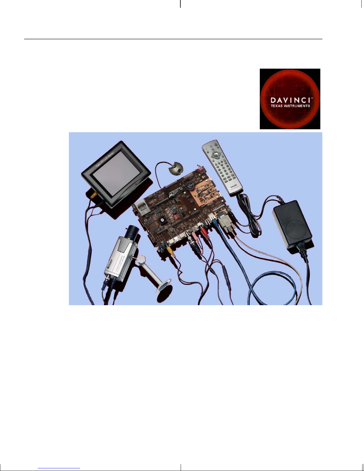
1.2 What’s in this Kit?
Your DVEVM kit contains the following hardware items. Section 2.1,
Setting Up the Hardware tells how to connect these components.
❏ EVM Board. This board contains a DaVinci TMS320DM6446 dua l-
❏ Hard Disk Drive. The hard drive provided w ith the EVM is a 2.5"
❏ CCD Camera. This camera provides NTSC or PAL video imaging for
❏ LCD Display. The LCD display prov ided with the DVEV M kit has a
What’s in this Kit?
core device with an ARM9 and C64+ DSP for development of
applications that use both a general-purpose processor and an
accelerated DSP proces s or.
Spinpoint drive with 40 GB of storage. The drive speed in 5400 RPM
and it has an 8MB cache. The drive is an Ultra A TA 66/100/133 IDE.
Software has been preloaded on this EVM board’s hard disk drive.
DaVinci applications.
5.6" screen and 320x240 pixels. Cables and a power supply are
provided. The NTSC v ersi on ha s a 110 VA C powe r supp ly. The PA L
version has a 220 VAC power supply.
❏ PC Desktop Microphone. The microphone provides a way to
capture audio for use by DaVinci applications.
❏ IR Remote Control. This universal remote control is included to
provide a user interface to the demo applications.
❏ Cables. Cables used to connect the EVM board to peripheral
devices and to a hos t Linux workstation used for devel opment are
provided in the kit.
The DVEVM kit also comes with the following software. Information about
how to use the software components is provided in Chapter 4.
❏ DaVinci Digital Video Evaluation Kit.
❏ TI DaVinci Demonstration Version of MontaVista Linux Pro v5.0
Target
❏ TI DaVinci Demonstration Version of MontaVista Linux Pro v5.0
Tools
❏ A/V Media Clips
❏ Spectrum Digital EVM Tools
❏ SoC Analyzer
DVEVM Overview 1-3
Page 12
What’s on the Board?
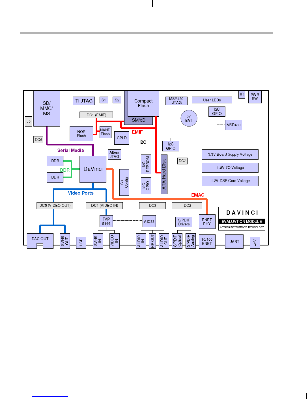
1.3 What’s on the Board?
The EVM comes lo aded with peripherals your mult imedia applications
may need to make use of. The hard dri ve on the bo ard al so co mes preloaded with demonstration software. The following block diagram shows
the major hardware components.
Figure 1–1 EVM Hardware Block Diagram
For more informa tion about the EVM hardware, see the DaVinci EVM
website at http://c6000.spectrumdigital.com/davincievm.
The DaVinci EVM incorporates a battery holder to provide backup power
to the MSP430’s real-ti me clock when the power is not ap plied to the
board. The battery is not inclu ded in the kit. See the Spectrum Digital
DaVinci EVM Technical Reference for suggested battery part numbers.
1-4
Diagram provided courtesy of Spectrum Digital Inc.
Page 13

1.4 What’s Next?
What’s Next?
To get started eval uati ng t he DV EVM k it a nd d ev elo pin g ap pli cati ons for
the DM644x, b egin by using this Getting Started guide. It will step you
through connecting the hardware, testing the software, and beginning to
develop applications.
When you are ready for more information about DaVinci Technology and
the DM644x architecture, see the following:
❏ Spectrum Digital website:
http://c6000.spectrumdigital.com/davincievm
❏ TI Linux Community for DaVinci Processors:
http://linux.davincidsp.com
❏ TI DaVinci Software Updates: http://www.ti.com/dvevmupdates
❏ TI DaVinci Technology Developers Wiki: http://wiki.davincidsp.com
❏ Codec Engine Application Developer's Guide (SPRUE67)
❏ Other PDF documents included with the DVEVM kit
❏ Section 4.11 lists documentation in the DVSDK software installation.
❏ SoC Analyzer Help menu
DVEVM Overview 1-5
Page 14

1-6
Page 15

EVM Hardware Setup
This chapter tells you how to set up the EVM hardware.
Chapter 2
Topic Page
2.1 Setting Up the Hardware. . . . . . . . . . . . . . . . . . . . . . . . . . . . . . . . . . . 2–2
2.2 Connecting to a Console Window . . . . . . . . . . . . . . . . . . . . . . . . . . . 2–6
2-1
Page 16
Setting Up the Hardware
2.1 Settin g U p the Hardware
To set up the hardware provided with the EVM, use the steps in the
sections that fo llow. You ma y sk ip secti ons if you do n ot ne ed to acce ss
a particular peripher al . Fo r examp le, i f y ou do no t n eed to us e the s erial
cable, skip that section.
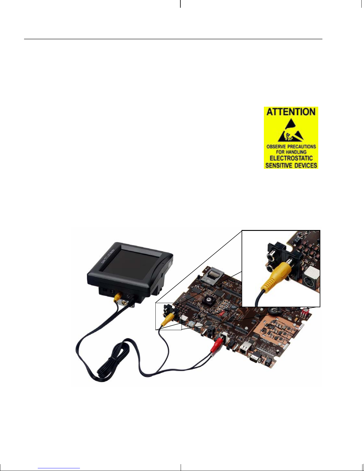
1) The EVM is sensitive to static discharges. Use
a grounding strap or other device to prevent
damaging the board.
Be sure to connect communication cables
before applying power to any equipment.
2) If you use PAL video, set switch 10 on the S3 (USER) bank of
switches to On. If you use NTSC video, set this switch to Off. See
Figure 1–1 for S3 switch bank location.
3) Connect the yellow v ideo cable to the upper-rig ht Video Out jack on
the EVM and the LCD display Video Input as shown below.
See Section A.1, Changing the Video Input/Output Methods for
information about using S-Video or Component video.
2-2
Page 17
Setting Up the Hardware
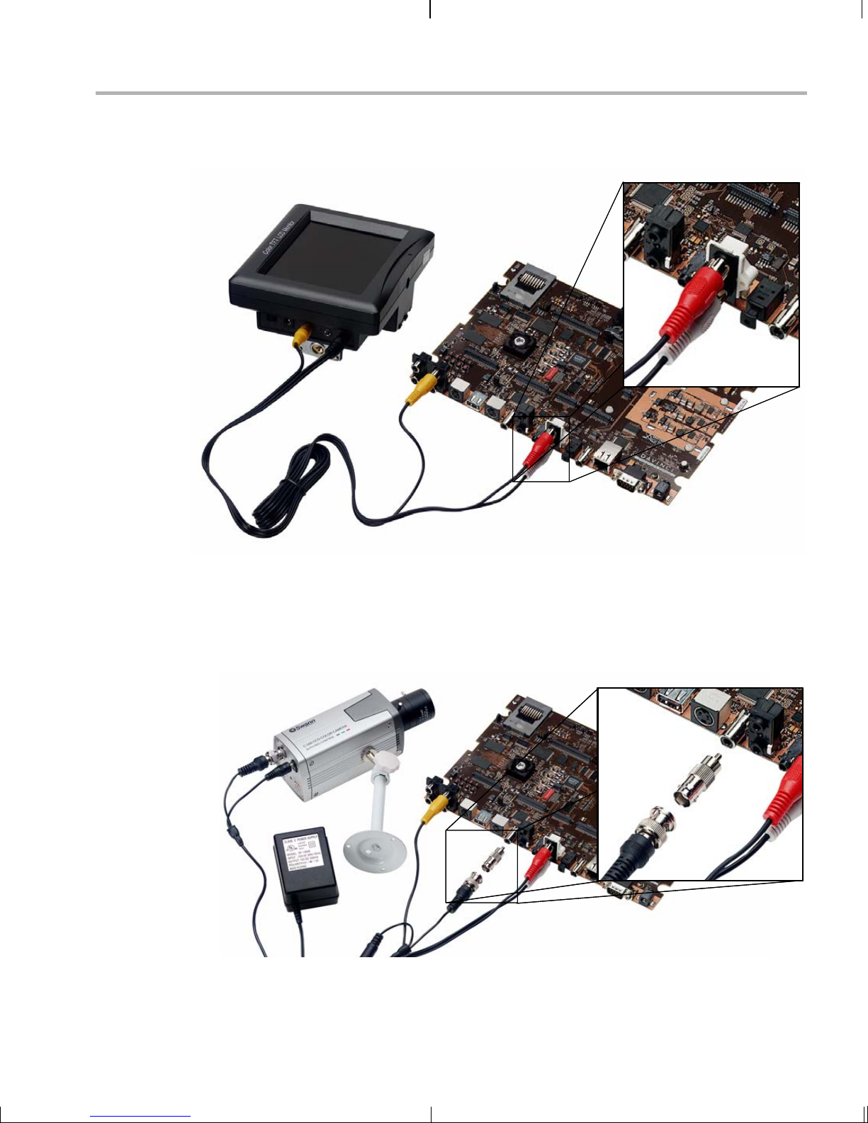
4) Connect the red and white audio cables to the EVM Audio Output
and the LCD display R/L Audio Input jacks as shown below:
5) Connect the BNC-to-RCA connector to the coax cable. Then connect
the coax cable to the video camera and the EVM Video Input.
6) Connect the power jack for the video camera. T o be ESD safe, do not
plug in the other end of the camera power cord until the later step that
instructs you to do so.
See Section A.1, Changing the Video Input/Output Methods for
information about using S-Video or Component video.
EVM Hardware Setup 2-3
Page 18
Setting Up the Hardware
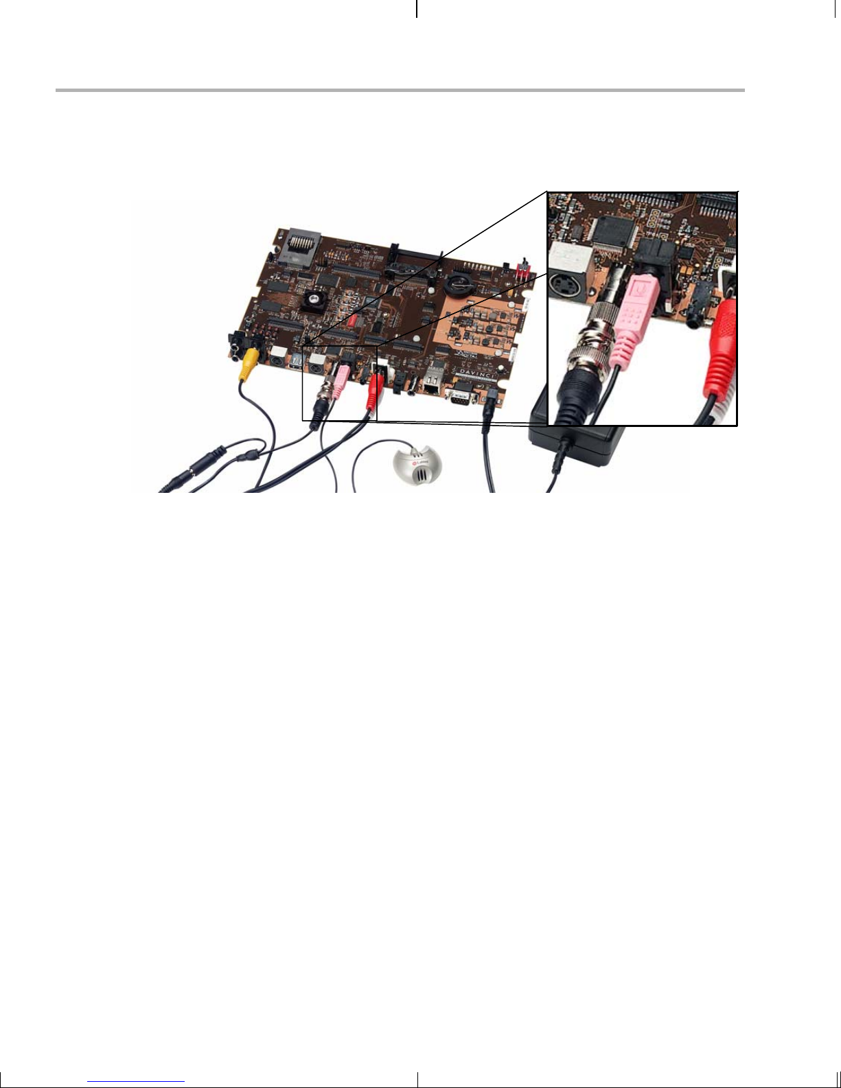
7) Connect the microphone to the EVM.
8) Connect the power cable to the EVM power jack on the board. To be
ESD safe, do not plug in the other end of the cable yet.
9) If you will use the Ethernet connection, connect the Ethernet cable to
the Ethernet Port on the EVM and to an Ethernet network port.
Note that the U-Boot bootargs must in clude "ip=dh cp" to enable the
network connection.
2-4
Page 19
Setting Up the Hardware
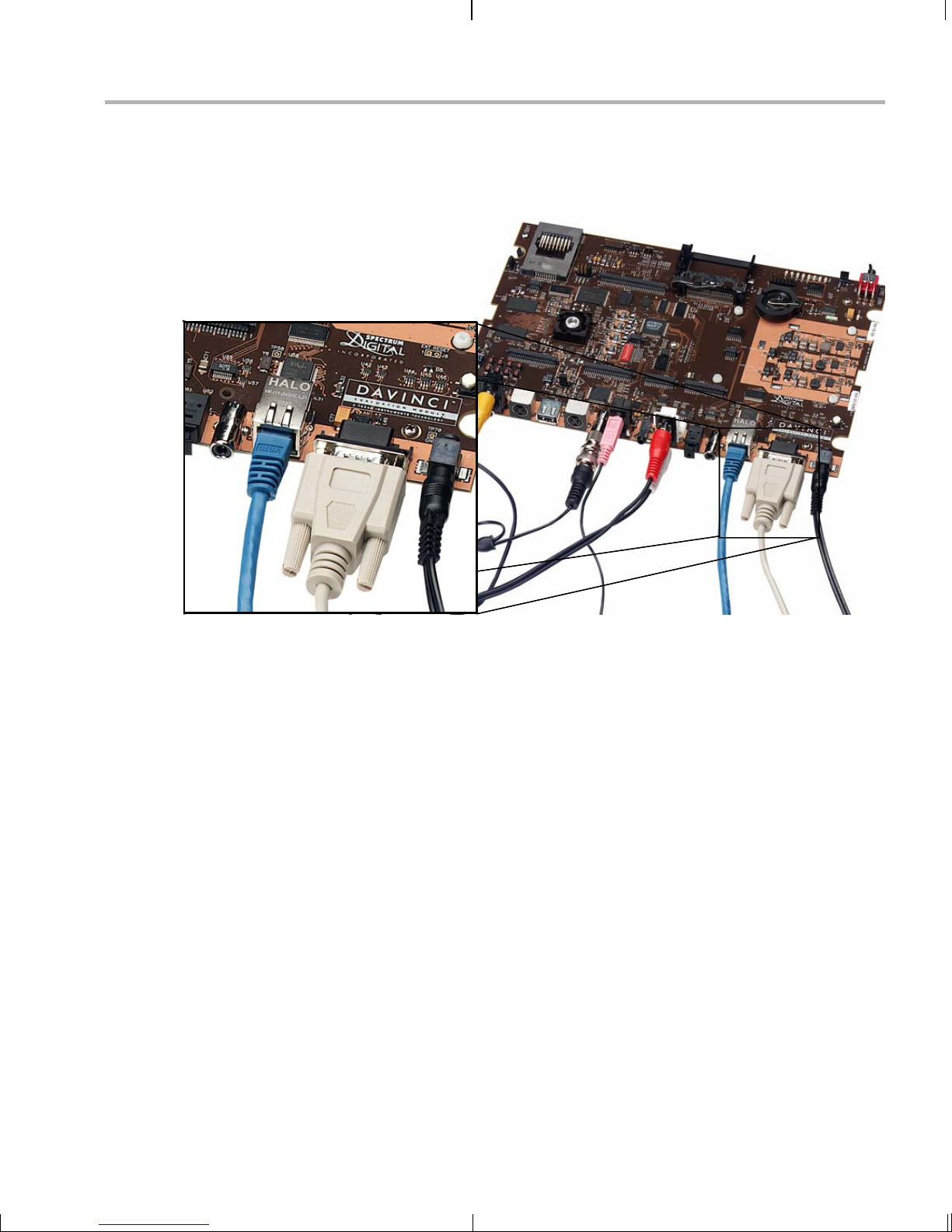
10) If you plan to use th e UART port for a co nsole windo w, connect the
RS-232 null modem cable to the EVM UART port and a COM port on
your host Linux workstation. See Section 2.2, Connecting to a
Console Window for more about using a console window.
11) Plug in the LCD display to a power supply.
12) Plug in the NTSC/PAL video camera to a power supply.
13) Connect the power cable to the EVM power jack on the board. To be
ESD safe, plug in the oth er end of the power cable only aft er you
have connected the power cord to the board.
14) Power on the LCD display.
15) Power on the EVM board.
16) The initial sc reen of the demo software should b e displayed o n the
LCD display. Use the IR r emote to run the software a s describ ed in
Chapter 3.
EVM Hardware Setup 2-5
Page 20

Connecting to a Console Window
2.2 Connecting to a Console Window
You can ope n a console window that allows you to watch an d interrupt
EVM boot messages by following these steps:
1) Connect a ser ial cable be tween the seri al port on the EVM and th e
serial port (for example, COM1) on a PC.
2) Run a terminal session (such as Minicom on Linux or HyperTerminal
on Windows) on th e workstation and config ure it to connect to tha t
serial port with the following characteristics:
■ Bits per Second: 115200
■ Data Bits: 8
■ Parity: None
■ Stop Bits: 1
■ Flow Control: None
3) When you power on the EVM, you will see boot sequence messages.
You can press a key to interrupt the boot sequence and type
commands in the U-Boot command shell. In this guide, commands to
be typed in the U-Boot shell are indicated by an
EVM # prompt.
2-6
Page 21
Chapter 3
Running the Demonstration Software
This chapter explains how to run the software demos prov ided with the
DVEVM kit.
Topic Page
3.1 Default Boot Configuration. . . . . . . . . . . . . . . . . . . . . . . . . . . . . . . . . 3–2
3.2 Starting the Standalone Demos. . . . . . . . . . . . . . . . . . . . . . . . . . . . . 3–2
3.3 Running the Standalone Demos . . . . . . . . . . . . . . . . . . . . . . . . . . . . 3–4
3.4 Running the Demos from the Command Line . . . . . . . . . . . . . . . . . 3 –9
3.5 Running the Network Demo . . . . . . . . . . . . . . . . . . . . . . . . . . . . . . . 3–11
3-1
Page 22

Default Boot Configuration
3.1 Default Boot Configuration
Out of the box, the EVM boots from flash and starts the demos
automatically after a few seconds when you power up the board. It does
not require an NFS mount or a TFTP server to run the standard demos.
Note: The default U-Boot bootargs definition sets "ip=off", which disables
the Ethernet connection.
The out-of-the-box boot parameters are listed in Section A.4.1. The
following are alternate ways you may want to boot the board:
❏ TFTP boot with hard drive file system (Section A.4.2)
❏ Flash boot with NFS file system (Section A.4.3)
❏ TFTP boot with NFS file system (Section A.4.4)
❏ PAL video mode vs. NTSC video mode (Section 4.3.7)
To abort the standard boot, press any key in th e console window (see
Section 2.2). Also see Section A.4, Alternate Boot Methods if you want to
change the boot configuration.
3.2 Starting the Standalone Demos
When you connect the EVM hardware, the pre-loaded examples run
automatically on the display. These examples encode and decode audio,
video, and speech. There are two ways to use the demos:
❏ Standalone. This is the default power-on mode. The demos run
automatically wi th n o connection to a wor kstation in the defa ult boo t
configuration. This is the mode documented in the rest of this
chapter.
The standalone demo was se t up by the DVSDK, which copies the
file /examples/dvevmdemo to the directory /etc/rc.d/init.d (the central
repository for startup scripts). This file is symbolically linked to
/etc/rc.d/rc3id/S88demo. When the board boots up and enters
runlevel 3, this file is ex ecute d to s tart th e de mo we b s erve r and th e
demo interface.
❏ Command line. Once you have connected the EVM to a workstation
and installed the nec ess ar y software (as desc ribe d i n S ec ti on 4.3.1 ,
Installing the T arget Linux Software), you can run the demos from the
board’s Linux command line. For furt her information on running the
demos from the comman d line, s ee the demo documentation th at is
linked to by the DVSDK release notes.
Note: When you run the demos fr om the comma nd line, make s ure
the interface process used by the standalone mode demos is not
3-2
Page 23
Starting the Standalone Demos
running. Otherwis e y ou wil l see er ro r me ss ag es rais ed whe n device
drivers fail to open.
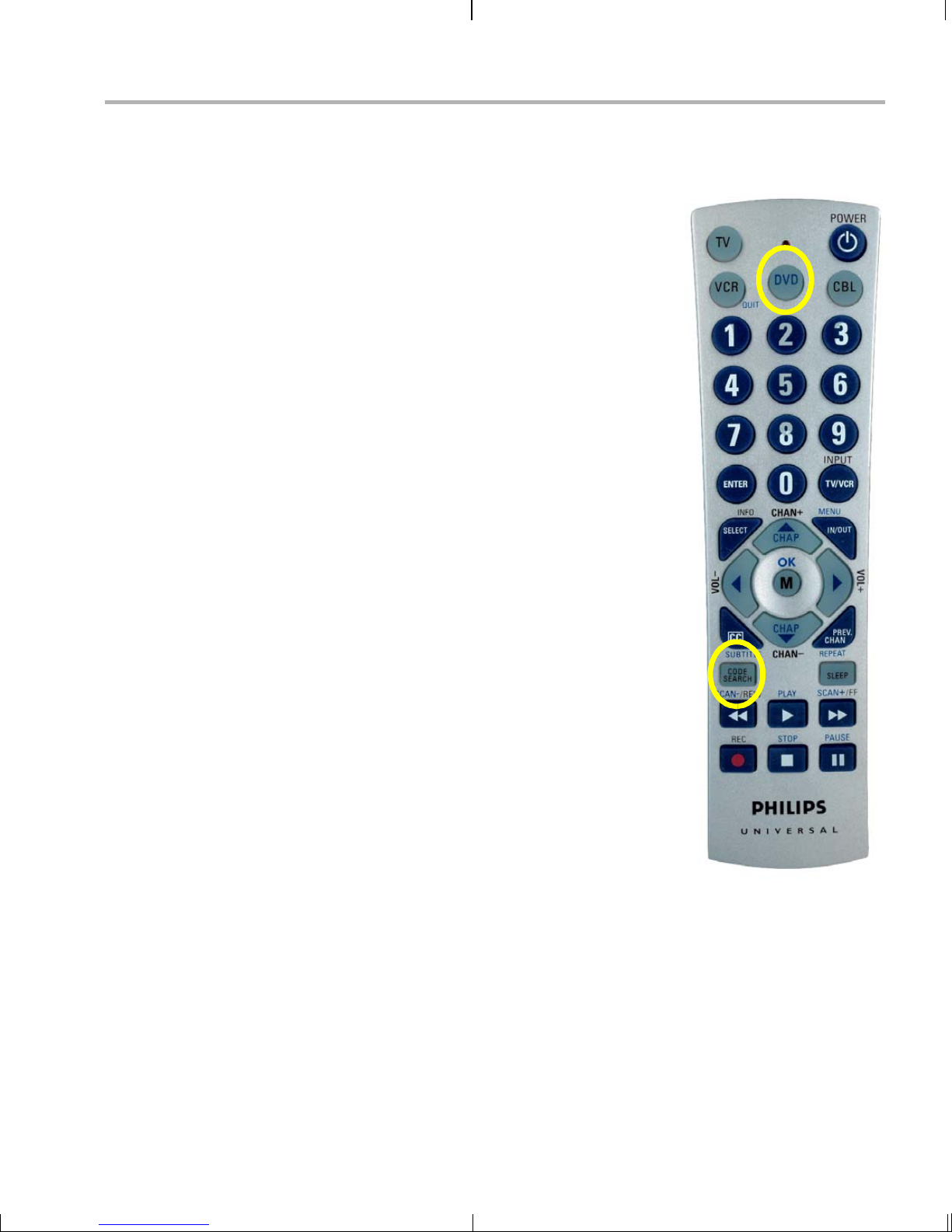
Once the EVM board has booted, the disp la y
should show a pi cture of the remote control.
You use the IR remote to control the demos.
The order of the buttons on the actual remote
may be different from the picture; if your
remote looks different, find the buttons with
the same labels on your remote.
To use the demos in standalone mode, follow
these steps:
1) Check to make sure the batteries are
installed in your IR remote.
2) The initial screen shows a diagram of the
IR remote, which you use to run the
standalone demos. Take a minute to look
at the functions of the various buttons.
3) Since this is a universal remote, you may
need to set it to use the codes necessary
to run the DVEVM demos. To do this,
hold down the "Code Search" button until
the red light on the remote stays lit. Then
press the "DVD" b utton an d enter "0020 "
as the code (for older remotes shipped
with the kit, the code is "020").
4) If you accidentally put the remote in TV or
some other mode , press " DVD" to return
the remote to the correct mode.
5) If the remote does not accept the
DVD+0020 code, do a full reset by
removing the batteries, pressing the
Power button for at least a minute, then
reinserting the batteries. Then program
the remote as in Step 3.
Running the Demonstration Software 3-3
Page 24

Running the Standalone Demos
3.3 Running the Standalone Demos
1) Press "Play" or "OK" on the remote to move from the remote control
diagram to the main menu screen, which looks like this:
The Encode + Decode demo allows you to record and playback
video. The Encode demo records audio/speech and video in the
formats you select. The Decode demo plays audio/speech and video
files you select. The Third-Party Menu can be used to add additional
demos (see Section A.2, Putting Demo Applications in the Third-
Party Menu).
2) Use the up and down arrows to change which demo is selected.
Then, press "OK" or "Play" to move to the selected demo.
3) Within a demo, you start at the settings
screen, where you see the controls
you can use to run the demo at the
bottom of the screen and the current
settings in the upper-right.
For example, the Encode demo allows
you to set the v ideo f ormat and the b it
rate at which video should be encoded.
Fixed settings are also shown here.
4) Use the up and down arrows to move to a setting you want to change.
3-4
Page 25

Running the Standalone Demos
5) Use the left and right arr ows to cycle through the options until the
setting you want is shown.
6) Press "Play" to begin the Encode+Decode and Decode demos.
Press "Rec" (record) twice to begin the Encode demo.
7) While the d emo runs, data about the settings , processor load, and
rates are shown. Static settings are on the right. Dynamic data
reporting is on the left. For example:
8) This informati on overl ays the v ideo; as a res ult the v ideo you s ee is
darker than the actual vi deo. To hide the infor mation disp lay so that
you can better see the video, press the "Info/Select" button on the IR
remote. Y ou can change the transparency of the OSD (overlay) while
running a demo by using the left and right arrows on the remote.
9) Press "Stop" or "Pause" when you want to end or pause a demo. The
first time you press "Stop", you return to the settings screen . Press
"Stop" from the settings screen to go back to the main menu.
For information about runn ing the individual demos, see Section 3.3. 2
through Section 3.3.4.
The demos use the Codec Engine to allow applications to run algorithms.
You ma y notic e that the DSP CP U load is initially high, ev en if t he DSP
is not running algorithms. The CPU load starts at 100% while the DSP is
booting and th en decr eases w hile th e DSP w aits for wo rk to b e requ ested
by the GPP. Even if DSP is idle, it may take a short amount of time
(several seconds) for the CPU load to settle to zero. This is because the
Codec Engine’s CPU load calculation includes a small amount of history.
3.3.1 Shut ting Down the Demos
You can quit out of the demos completely while at the main menu screen
by pressing "Power" on the remote.
To restart the dem os, you can reboot the boa rd or run the demos f rom
the command line as described in Sec ti on 3.4.
Running the Demonstration Software 3-5
Page 26

Running the Standalone Demos
3.3.2 About the Encode + Decode Demo
The Encode + Dec ode demo allows you to r ecord and playback vi deo.
Video comes from the camera, is encoded, then decoded, and then sent
to the LDC display.
The Encode + Dec ode does only video pr ocessing; it does no t encode
and decode audio or speech. The suppor ted video algorithm is H.264
Baseline Profile (.264 fil e exte ns ion ).
Table 3–1 IR Remote Buttons for Encode + Decode Demo
IR Remote Button Mode Action Performed
Up/Down -- -- no action -Play or OK Setup Begin demo
Record -- -- no action -Info/Select Setup Show / hide block diagram for demo
Info/Select Run Toggle information display
Left/Right Run Change information transparency level
Pause Run Pause demo (press Play to resume)
Stop Setup / Run Return to previous screen
The application runs on the ARM using Linux. The video signal is passed
to video encoders and decoders on the DSP by the Codec Engine.
Shared memory is used when passing data.
To use this dem o from the c ommand l ine, see Sec tion 3.4, Run ning the
Demos from the Command Line.
3-6
Page 27

3.3.3 About the Encode Demo
Like the Encode + Decode demo, the Encode demo also encodes video.
In addition, it also encodes speech. The speech source is the
microphone.
The encoded data is written to files on the EVM’s hard disk drive. Th e
possible filenames are demo.264, demo.mpeg4, demompeg4.g711, and
demo264.g711. Older versions of these files are overwritten as needed.
Output is not de coded and s ent to the d isplay or s peak ers othe r than t o
show the settings and dynamic data collected about the load and rates.
Running the Standalone Demos
Note that you can use only a speech encoder, not an audio encoder. The
supported video algorithms are MPEG4 (.mpeg4 file extension) and
H.264 (.264 file extension). The supported speech algorithm is G.711
(.g711 extension).
Table 3–2 IR Remote Buttons for Encode Demo
IR Remote Button Mode Action Performed
Up/Down Setup Change option selection
Left/Right Setup Change setting of selected option
Play Setup Switch to decode demo setup
Record (twice)
or OK
Setup / Run Begin encode demo, send unencoded
data to display
Running the Demonstration Software 3-7
Page 28

Running the Standalone Demos
Table 3–2 IR Remote Buttons for Encode Demo
IR Remote Button Mode Action Performed
Info/Select Setup Show / hide block diagram for demo
Info/Select Run Toggle information display
Left/Right Run Change information transparency level
(There is no display for encode demo
behind the information.)
Pause Run Pause demo (press Record to resume)
Stop Setup / Run Return to previous screen
The application runs on the ARM using Linux. The video and audio
signals are passed to encoders on the DSP by the Codec Engine. Shared
memory is used when passing data.
To use this dem o from the c ommand l ine, see Sec tion 3.4, Run ning the
Demos from the Command Line.
3.3.4 About the Decode Demo
The Decode demo pla ys audio/speech and video fil es you select. Yo u
can select a source video file and a source audio or speech file. Use the
left and right arrow bu ttons to choose from the demo files and the files
created by the E ncode demo, whi ch are store d on the EV M’s hard disk
drive. The decoded signals are sent to the display and speakers.
3-8
Page 29

Running the Demos fr om the Command Line
The supported video algorithms are MPEG4 (.mpeg4 file extension),
H.264 (.264 file extension) and MPEG2 (.m2v file extension).
The supported audio algorithm is AAC (.aac file extension). The
supported speech algorithm is G.711 (.g711 file extension).
Table 3–3 IR Remote Buttons for Decode Demo
IR Remote Button Mode Action Performed
Up/Down -- -- no action -Left/Right Setup Select a different file combination
Play or OK Setup Begin decode demo
Record -- -- no action -Info/Select Setup Show / hide block diagram for demo
Info/Select Run Toggle information display
Left/Right Run Change information transparency level
Pause Run Pause demo (press Play to resume)
Stop Setup / Run Return to previous screen
The application runs on the ARM using Linux. The video and audio
signals are passed to decoders on the DSP by the Codec Engine. Shared
memory is used when passing data.
To use this dem o from the c ommand l ine, see Sec tion 3.4, Run ning the
Demos from the Command Line.
3.3.5 About the Third Party Menu
The Third-Party Menu can be used to add additional demos. See Section
A.2, Putting Demo Applications in the Third-Party Menu.
3.4 Running the Demos from the Command Line
You can run the demo applications from the Linux shell in a terminal
window connected to the EVM b oard’s serial port. T hese are the s ame
demos described in Section 3.2, Starting the Standalone Demos.
1) See Section 2.2, Connecting to a Console Wi ndow for instructions
regarding communicating with Linux running on the EVM.
2) Login to the target as root. No password is required.
Running the Demonstration Software 3-9
Page 30

Running the Demos from the Command Line
3) Move to the ap propriate directory on the target using the following
command. (See Section 4.1.1 for the meanings of command prompts
shown in this document.)
Target $ cd /opt/dvsdk/dm6446
4) Before running demo applications from the command line, the CMEM
and accelerator kernel modules must be loaded.
■ Use "lsmod" to see if they are loaded. You should see output
similar to the following:
Target $ lsmod
Module Size Used by
dsplinkk 98220 0
cmemk 20072 0
■ If they are not loaded, use the following commands to load these
modules.
Target $ ./loadmodules.sh
5) If a standalone demo is running, kill that process. You can do this by
pressing the Power bu tton on the remote from the main menu. Or,
use the following commands:
Target $ killall -9 interface
6) To see the command-line options for the demos, use one of the
following commands with the -h or --help option:
Target $ ./encodedecode -h
Target $ ./encode -h
Target $ ./decode -h
7) To stop a demo, press Ctrl+C at the command line or press the Stop
button on the remote.
You can also find the list of command-line options in encode.txt,
decode.txt, and enc odedecode.txt in the r espective demo d irectories of
the DVSDK package on the host.
Note: When you run loadmodules.sh, you may see warnings about
the kernel being tainte d by cmemk and dsplinkk. You can ignore
these warnings. They occur becau se DSP/B IO S Link doe s not us e
the kernel build sys tem and is not under the same licen se as the
kernel itself.
3-10
Page 31

3.5 Running the Network Demo
As an example of standard TCP/IP networking support, the DVEVM
examples include a small HTTP web server. This web server is started
on the GPP-side as part of the Linux startup sequenc e. It configured to
service requests from web browsers on the standard TCP/IP port 80.
After the EVM board has booted, connect a P C to the same network to
which the EVM board is conne cted. Enter a URL of the form "http://ipaddress-of-evm" in a web browser (for example, Internet Explorer,
Firefox, or Opera). The IP address of the board is shown in the lower-right
corner of the main menu of the A/V demos.
You sho uld see a web page with info rmation about DaVinci technol ogy
and the DVEVM software.
Running the Network Demo
Use this web page to interact with the board and run the A/V demos
described in Section 3.3, Running the Standalone Demos. Two simple
CGI scripts on the EVM enable you to start the demos (assuming they are
not already running) and see what processes ar e running on th e board.
If you want to see the demo started from the web page, be sure to exit
the demo first (use the Power button from the main menu).
The web server software is an open-source package called THTTPD
(http://www.acme.com/software/thttpd/). It is designed to be small , fast,
and portable. The source code is included with the DVEVM software. You
can get the latest version directly from the web. The web server and CGI
scripts are installed on the target in the /opt/dvsdk/dm6446/web directory .
Running the Demonstration Software 3-11
Page 32

3-12
Page 33

Chapter 4
DVEVM Software Setup
This chapter explains how to use the software provided with the DVEVM
kit.
Topic Page
4.1 Software Overview . . . . . . . . . . . . . . . . . . . . . . . . . . . . . . . . . . . . . . . 4–2
4.2 Preparing to Install . . . . . . . . . . . . . . . . . . . . . . . . . . . . . . . . . . . . . . . 4–5
4.3 Installing the Software . . . . . . . . . . . . . . . . . . . . . . . . . . . . . . . . . . . . 4–5
4.4 Setting Up the Build/Development Environment . . . . . . . . . . . . . . 4–13
4.5 Building a New Linux Kernel . . . . . . . . . . . . . . . . . . . . . . . . . . . . . . 4–14
4.6 Rebuilding the DVEVM Software for the Target . . . . . . . . . . . . . . . 4–16
4.7 Booting the New Linux Kernel . . . . . . . . . . . . . . . . . . . . . . . . . . . . . 4–17
4.8 Testing the Build Environment. . . . . . . . . . . . . . . . . . . . . . . . . . . . . 4–18
4.9 Using the Digital Video Test Bench (DVTB) . . . . . . . . . . . . . . . . . . 4–18
4.10 Running The SoC Analyzer . . . . . . . . . . . . . . . . . . . . . . . . . . . . . . . 4–20
4.11 Documentation for DSP-Side Development . . . . . . . . . . . . . . . . . . 4–21
4-1
Page 34

Software Overview
4.1 Software Overview
To begin developing applications, you need to install the DVEVM
development environment. This chapter outlines the steps required to
load the DVEVM softwa re onto the deve lopmen t host. You will need the
distribution disks or the files they contain to get started.
The DaVinci software approach provides interoperable, optimized,
production-ready video and audio codecs that leverage DSP and
integrated accelerators. These codecs are built into configurable
frameworks, and are presented via published APIs within popular
operating systems (such as Linux) for rapid software implementation.
The following software is provided with the DVEVM.
❏ Standalone demonstration software. This is provided on the hard
❏ Disk 1: MontaVista Linux Pro v5.0 System Tools and Target File
drive on the EVM. The hard-wired examples encode and decode
audio, video, and speech. Another demo shows the board’s network
capabilities. See Section 3.2 and Section 3.5.
System. The version provided with the DVEVM kit is the
demonstration version. It contains the following file:
■ mvl_5_0_demo_sys_setuplinux.bin. This installation file
contains the MontaVista Tool development tool chain and the
target file system.
❏ Disk 2: TI DVSDK Software. This DVD includes demo applications,
Codec Engine software, example codec servers, and DVEVM
documentation. It contains the following files:
■ this manual in PDF format
■ dvsdk_setuplinux_#_#_#_#.bin (DV S DK ins taller )
■ mvl_5_0_0_demo_lsp_setuplinux_#_#_#_#.bin
■ xdctools_setuplinux_#_#_#.bin (XDCtools installer)
■ bios_setuplinux_#_#_#.bin (DSP/BIOS installer)
■ TI-C6x-CGT-v#.#.#.#.bin (TI Code Generation Tools installer)
■ SoCAnalyzer_#.#.#.#.exe. SoC Analyzer installer.
■ data.tar.gz (Contains A/V data files for use by the demos)
■ restore/overlay.tar.gz (Contains demo files in case they are
needed for recovery. You can generally ignore this file.)
❏ Disk 3: SDI Board Support Software. This disk contains ARM-
based test code, CCStudio GEL files, and other EVM support
software.
4-2
Page 35

Texas Instruments, in agreement with MontaVista Software Inc., is
providing a demons trati on ver s io n of th e Li nux Prof es si ona l E dit ion v5.0
embedded operatin g system a nd developm ent tools . The base DVEVM
kit includes this de monst ratio n vers ion. The dem o ve rsion is a subse t of
what MontaVista provides with the fu ll Professional Edition. Tools such
as DevRocket
TM
and the Professional Edition documentation are not
included, but it is otherwise fully functional and useful for customers
evaluating the DaVinci platform. Also, please note that this release does
not include a MontaVista user lice nse, and no direct custo mer support,
warranty, or indemnification from MontaVista Software Inc. is provided.
You may choose to order the DaVinci Software Production Bundle
(DVSPB), which includes the prod uction release of this demonst ration
version of MontaVista Linux. T his inc ludes a f ull Mo ntaVista licens e and
the DevRocket IDE.
4.1.1 Command Prompts in This Guide
In this guide, commands are preceded by prompts that indicate the
environment where the command is to be typed. For example:
Software Overview
❏
host $
Indicates command to be typed into the shell window of the host
Linux workstation.
❏
EVM #
Indicates commands to be typed into the U-Boot shell in a console
window connected to the EVM board's serial port. (Section 2.2)
❏
target $
Indicates command s to be typed i nto the Linux shel l in the terminal
window connected to the EVM board's serial port.
DVEVM Software Setup 4-3
Page 36

Software Overview
4.1.2 Software Components
The following figure shows the software components used for application
development with the DVEVM kit:
A pp lic atio n
I/O
I/O
I/O
DMAI
VISA API
Codec Engine
Operating System
Adaptation Layer
(OSAL)
User Space
VID IMG
SPH AUD
Engine
Server
xDM
xDM
Speech Co dec
Speech Co dec
API
API
V-Node
V-Node
Video-Task
Video-Task
xDM
xDM
API
API
VISA APIVISA API
S-Node
S-Node
Speech-Task
Speech-Task
xDM
xDM
API
API
Video
Video
Codec
Codec
Speech
Speech
Codec
Codec
I-Node
I-Node
Image-Task
Image-Task
xDM
xDM
Imag in g
Imag in g
API
API
Codec
Codec
A-Node
A-Node
Audio-Task
Audio-Task
xDM
xDM
Audio
Audio
API
API
Codec
Codec
Kernel Space
CMEM
Driver
File
(ATA)
GP
I/O I/O I/O
Timer
USB 2.0
Dri ver
MMC/SD
Driver
Wat ch dg
Timer
ARM Subsystem DSP Subsystem + Co-Processor
Linux APIsLinux APIs
EMAC
Dri ver
SPI
Dri ver
I2C
Dri ver
In the previous fi gure, your applica tion runs on the ARM subsystem. It
handles I/O and application processing. To process video, image,
speech, and a udio signals it u se s the VISA APIs prov ide d by the Codec
Engine. The Codec Engine, in turn, uses services suc h as DSP/BIOS
Link and protocols such a s xDA IS an d xDM to com municate with a preconfigured Codec Eng ine Remote Server on the DSP subsystem. The
DSP handles signal processing and the results are available to the ARM
subsystem in shared memory. For more information, see the Codec
Engine Application Developer's Guide (SPRUE67).
Video
Dri ver
Link
Driver
Audio
Driver
UART
Driver
DSP/BIOS™ Link
Transport
Framework
Framework
Framework
Components
Components
Components
DMAN3 ACPY3
DMAN3 ACPY3
DMAN3 ACPY3
DMAN3 ACPY3
DSKT2
RMAN
DSKT2
RMAN
DSKT2
RMANDSKT2
RMAN
DSP/BIOS™
Codec
Codec
Codec
Engine
Engine
Engine
Remote
Remote
Remote
Server
Server
Server
In addition, Linux runn ing on the ARM makes a large number of APIs
available to your application, including drivers and timers.
4-4
Page 37

4.2 Preparing to Install
On a host system, mount the DVE VM demo nstratio n DVD and co py the
following files to a temporary location with at least 2.3 GB available
space. Since you can delete the installation files after installing the
software, a directory like /tmp is recommended.
❏ mvl_5_0_demo_sys_setuplinux.bin (disk 1)
❏ mvl_5_0_0_demo_lsp_setuplinux_#_#_#_#.bin (disk 2)
❏ dvsdk_setuplinux_#_#_#_#.bin (d is k 2)
❏ xdctools_setuplinux_#_#_#.bin (disk 2)
❏ bios_setuplinux_#_#_#_#.bin (disk 2)
❏ TI-C6x-CGT-v#.#.#.#.bin (disk 2)
Updates to these installer s may be av ail ab le on the T I DaVinci S oftw ar e
Updates website listed in Section 1.4.
Ensure that an X g ra phic al d is pla y i s a va ilabl e, an d po int y ou r DI SP LAY
environment variable to this value. For example:
Preparing to Install
csh:
host $ setenv DISPLAY cnabc0314159d1:0
ksh or bash:
host $ export DISPLAY=cnabc0314159d1:0
4.3 Installing the Software
Installing the software used by the DVEVM involves performing the
following steps:
❏ Section 4.3.1, Installing the Target Linux Software
❏ Section 4.3.2, Installing the DVSDK Software
❏ Section 4.3.3, Installing the A/V Demo Files
❏ Section 4.3.4, Installing the SoC Analyzer
❏ Section 4.3.5, Exporting a Shared File System for Target Access
❏ Section 4.3.6, Testing the Shared File System
❏ Section 4.3.7, Configuring the Boot Setup for PAL Video Users
DVEVM Software Setup 4-5
Page 38

Installing the Software
4.3.1 Installing the Target Linux Software
This section explains how to install Linux for use on the target board. This
is a demonstration version of MontaVista Linux Pro v5.0.
Note that separate versions of Linux are used by the target and your host
Linux workstation. The fol lowing Linux host operating sys tem is tested
with the DVEVM: Red Hat Enterprise Linux v4 (Server Edition).
To install the Linux software, follow these steps:
1) Log in as root on you r host Linux wor kstatio n. This will all ow you t o
successfully run the graphical installer to install MontaVista Linux.
2) Execute each of the following bin files (where
#_#_#_# is the current
version number) from the temporary location that they were copied in
order to extract the installers for the Linux tools, Linux kernel, and the
file system. If a bin file does not run, make sure these files are
executable (use
chmod +x *.bin).
Instead of the default installation directory, we suggest that you
change the installation directory to /opt/mv_pro_5.0.
host $ ./mvl_5_0_demo_sys_setuplinux.bin
host $ ./mvl_5_0_0_demo_lsp_setuplinux_#_#_#_#.bin
3) After you execu te these .bin files, make sure the following files are
located in /opt/mv_pro_5.0 (or in the /mv_pro_5.0 subdirectory of the
directory you chose in place of the default):
■ mvltools5_0_#######.tar.gz
■ DaVinciLSP_#_#_#_#.tar.gz
4) Go to the location where you will unpack the tar files. For example:
host $ cd /opt/mv_pro_5.0
5) Unpack the tar files (as root) by using the following commands:
host $ tar zxf mvltools5_0_#######.tar.gz
host $ tar zxf DaVinciLSP_#_#_#_#.tar.gz
This creates the MontaVista directory structure under the
/opt/mv_pro_5.0/mo ntavista/ direc tory.
Note that unpacking these tar files will overwrite any existing files that
were previously installed.
Note: The LSP shipped with the DVS DK i s a mu lti -pla tfor m LS P; it
is not configured for a particular platform. As shipped, this LSP
cannot be used to buil d the d emo or exa mple a pplicat ions. It mus t
first be copied to a user area and configured/built for the EVM.
Please see Section 4.5 for instructions.
4-6
Page 39

4.3.2 I nstalling the DVSDK Software
The DVSDK softwar e includes Codec Engine componen ts, DSP/BIOS
Link, sample data file s, xDAIS and xDM header files, and a contigu ous
memory allocator for Linux (CMEM).
Note: The installers for DSP/BIOS and Code Generation Tools
(codegen) have a different default installation location. However,
we strongly recommend that you change the default installation
locations to place the components together (if you have not already
installed the Linux ve rsions of th ese compo nents elsewhere ). This
simplifies the build setup steps.
To install the DVSDK software using the Linux installer, follow these
steps:
1) Log in using a user account. The user accou nt must have exe cute
permission for the dvsdk_setuplinux_#_#_#_#.bin and
xdctools_setuplinux_#_#_#.bin files.
Installing the Softwa re
2) Execute the DVSDK installer that you previously copied from the
DVSDK DVD. For example:
host $ cd /tmp
host $ ./dvsdk_setuplinux_#_#_#_#.bin
This installs the DVSDK in /home/<useracct>/dvsdk_#_#.
3) Execute the XDC installer that you previously copied from the
DVSDK DVD. For example:
host $ ./xdctools_setuplinux_#_#_#_#.bin
When you are prompted, do not us e th e de faul t i ns tallation location.
Instead, install the softwar e in the directory created in Step 2. For
example, /home/<useracct>/dvsdk_#_#.
4) Execute the DS P/BIO S in staller th at yo u previ ously c opie d from th e
DVSDK DVD. For example:
host $ ./bios_setuplinux_5_#_#_#.bin
When you are prompted, do not us e th e de faul t i ns tallation location.
Instead, install the softwar e in the directory created in Step 2. For
example, /home/<useracct>/dvsdk_#_#.
5) Execute the Code Generation Tools installer that you previously
copied from the DVSDK DVD. For example:
host $ ./TI-C6x-CGT-v#.#.#.#.bin
DVEVM Software Setup 4-7
Page 40

Installing the Software
When the installer prompts for an installation location, do not use the
default location. Instead, use the entire path to the dvsdk_#_#
codegen directory. You will need to manually create the folder
cg6x_6_#_#, where # represents part of the version number. For
example:
/home/<useracct>/dvsdk_#_#/cg6x_6_0_16.
Remember to set the environment variable as directed by the
installer. For example:
C6X_C_DIR="/home/<useracct>/dvsdk_#_#/cg6x_6_#_#/include:
/home/<useracct>/dvsdk_#_#/cg6x_6_#_#/lib"
6) You can now delete the .bin fi les that y ou load ed into the tem pora ry
directory.
Note: You can uninstall these components by using the rm -rf
command on its directory. You should ignore the uninstall files
created by the installer.
4.3.3 Installing the A/V Demo Files
Disk 2 contains the A/V files used by the demos. After following the
instructions in the previous section, follow these instructions to install the
A/V files:
1) Go to the DVSDK directory that you set up previously. For example:
host $ cd /home/<useracct>/dvsdk_#_#
2) Mount disk 2 and copy the data.tar.gz file to your DVEVM direc tory.
For example:
host $ cp <mount location>/data.tar.gz .
3) Extract the A/V data files. For example:
host $ tar xfz data.tar.gz
4-8
Page 41

4.3.4 Installing the SoC Analyzer
SoC Analyzer is a graphical tool that runs on a Windows develop ment
host and uses data collected fr om Linux, DSP/BIOS , and Codec En gine
to provide system-level execution and performance analysis for
debugging and profiling DVEVM software execution. Follow these
instructions to install SoC Analyzer:
1) Insert the TI DVS DK software disk into the Windows de velopment
host PC.
2) Browse to the SoCAnalyzer/WinXP folder.
3) Double-click on the SoCAnalyzer_#.#.#.#.exe file to start the
installer.
4) Follow the installer’s prompts to install the software.
4.3.5 Exporting a Shared File System for Target Access
Although the board’s hard drive contains a file system, during
development it i s more co nvenient to have the target boar d NFS m ount
a file system on a host Linux workstation. Once you have tested the
application, yo u can store it on the board’s hard dr ive for a standalone
demonstration.
Installing the Softwa re
Note: Using video files from an NFS file system may result in a low
frame rate when encoding/decoding videos.
Before the board can mount a target file system, you must export that
target file system on the host Linux workstation. The file system uses an
NFS (Network File Sys tem) se rv er. The exported file s yste m wi ll co ntain
the target file system and your executables.
To export the file system from your NFS server, perform the following
steps. You only need to perform these steps once.
1) Log in with a user account on the host Linux workstation.
2) Perform the following commands to prepare a location for the
MontaVista file system. For example:
host $ cd /home/<useracct>
host $ mkdir -p workdir/filesys
host $ cd workdir/filesys
3) Switch user to "root" on the host Linux workstation.
host $ su root
DVEVM Software Setup 4-9
Page 42

Installing the Software
4) Perform the fol lowing commands to cr eate a copy of the target file
system with permissions set for writing to the shared area as
<useracct>. Substitute your user name for <useracct>. If you
installed in a location other tha n /opt/mv_pro_5.0, us e your locatio n
in the cp command.
host $ cp -a /opt/mv_pro_5.0/montavista/pro/devkit/arm/v5t_le/target/* .
host $ chown -R <useracct> opt
5) Edit the /etc/exports file on the host Linux workstation (not the
exports file on the target filesystem). Add the following line for
exporting the filesys area, substituting your user name for
<useracct>. Use the full path from root; ~ may not work for exports
on all file systems.
/home/<useracct>/workdir/filesys *(rw,no_root_squash,no_all_squash,sync)
Note: Make sure you d o no t ad d a s pace betw een the * a nd the ( in
the above command.
6) Still as root, use th e following commands to make the NFS serv er
aware of the change to its configuration and to invoke an NFS restart.
host $ /usr/sbin/exportfs -av
host $ /sbin/service nfs restart
Note: Use exportfs -rav to re-export all directories. Use
/etc/init.d/nfs status to verify that the NFS status is running.
7) Verify that the server firewall is turned off:
host $ /etc/init.d/iptables status
If the firewall is running, disable it:
host $ /etc/init.d/iptables stop
4-10
Page 43

4.3.6 Testing the Shared File System
To test your NFS setup, follow these steps:
1) Get the IP addre ss of your host L inux workstatio ns as foll ows. L ook
for the IP address associated with the eth0 Ethernet port.
host $ /sbin/ifconfig
2) Open a termi nal e mul ation win dow to connect to the E VM bo ar d vi a
RS-232 using the instructions in Section 2.2. If you have a Windows
workstation, you can use HyperTerminal. If you have a Linux
workstation, you might u se Minicom. (You may need to turn on line
wrap.)
3) Power on the EVM board, and abort the automatic boot sequence by
pressing a key in the console window (Section 2.2).
4) Set the following environment variables in the console window:
EVM # setenv nfshost <ip address of nfs host>
EVM # setenv rootpath <directory to mount>
EVM # setenv bootargs video=davincifb:vid0=720x576x16,
2500K:vid1=720x576x16,2500K:osd0=720x576x16,2025K
davinci_enc_mngr.ch0_output=COMPOSITE
davinci_enc_mngr.ch0_mode=$(videostd)
console=ttyS0,115200n8 noinitrd rw ip=dhcp
root=/dev/nfs nfsroot=$(nfshost):$(rootpath),nolock
mem=120M
Installing the Softwa re
Note that the setenv bootargs command should be typed on a
single line. Also note that you should avoid using the numeric keypad
to enter numbers, as it can sometimes insert extra invisible
characters.
<directory to mount> must match what you specified in Step
The
5 of Section 4.3.5. For example, /home/<useracct>/workdir/filesys.
Hints: You may want to us e the printenv comm and to print a list of
your environment variables. You can also save these setenv
commands in a .txt file from which you can paste them in the future.
5) Save the environment so that you don't have to retype these
commands every time you cycle power on the EVM board:
EVM # saveenv
6) Boot the board using NFS:
EVM # boot
7) You can now log in as "root" with no password required.
DVEVM Software Setup 4-11
Page 44

Installing the Software
See Section A. 4, Alternate Boot Methods fo r information about boo ting
with TFTP or NFS and using flash or the EVM’s hard drive.
4.3.7 Configuring the Boot Setup for PAL Video Users
You can configure the EVM to select either the NTSC or PAL video
standard during the d efault boot sequence. To select PAL, set swi tc h 1 0
on the S3 (USER) user bank of switches to On. For NTSC, set this switch
to Off. The switch causes th e U-Boot env ironm ent vari able "vid eostd" to
be set to "pal" or "ntsc".
Using the "videostd" variable in the "bootargs" environment variable
passed to the Linux kernel ca uses the cor responding video standard t o
be used by the display (VPBE) driver. For example:
EVM # setenv bootargs video=davincifb:vid0=720x576x16,
2500K:vid1=720x576x16,2500K:osd0=720x576x16,2025K
davinci_enc_mngr.ch0_output=COMPOSITE
console=ttyS0,115200n8 noinitrd rw ip=dhcp
root=/dev/hda1 mem=120M
EVM # setenv bootcmd 'setenv setboot setenv bootargs
\$(bootargs) davinci_enc_mngr.ch0_mode=\$(videostd); run
setboot; bootm 0x2050000'
When the "boot" comm and is run in U-Boot, the value of "videostd" is
substituted based on the setting of the switch.
See Section A.1, Changing the Video Input/Output Methods for
information about switching to S-Video and Component video.
4.3.8 Notes on Using Evaluation/Production Codecs
As part of the DVSDK installation, you received a number of codecs:
❏ H.264 Base Profile Decoder
❏ H.264 Base Profile Encoder
❏ MPEG4 Restricted Simple Pr ofile Dec ode r
❏ MPEG4 Simple Profile Encoder
❏ MPEG2 Decoder
❏ AAC Decoder
❏ MP3 Decoder
❏ G.711 Decoder (not a TI codec)
❏ G.711 Encoder (not a TI codec)
4-12
Page 45

Setting Up the Build/Development Environment
These codecs are provided under a "for demonstration-only" license
agreement. If you wish to use these codecs in a production development
environment, you can go to the DVEVM Updates web site at
http://www.ti.com/dvevmupdates to download the latest production
versions, along with the appropriate license agreement.
4.4 Setting Up the Build/Development Environment
To set up the GPP-side development and build environment, follow these
steps:
1) Log in to your user account (and not as root) on the NFS host
system.
2) Set your PA TH so that the MontaVista tool chain host tools and cross
compiler (arm_v 5t_le-gcc) can be found. For exam ple, in a default
installation of the MontaVista LSP, you should add a definition like
the following to your shell resource file (for example, ~/.bashrc):
PATH="/opt/mv_pro_5.0/montavista/pro/devkit/arm/v5t_le/bin:
/opt/mv_pro_5.0/montavista/pro/bin:
/opt/mv_pro_5.0/montavista/common/bin:$PATH"
If you installed in a location other than /opt/mv_pro_5.0, use your
own location in the PATH.
3) Remember to use the following command after modifying your
.bashrc file:
host $ source ~/.bashrc
4.4.1 Writing a Simple Program and Running it on the EVM
Make sure you have performed the steps in Section 4.3.5, Exporting a
Shared File System for Target Access and Section 4.4, Settin g Up the
Build/Development Environment.
Perform the following steps on the NFS host system as user (not as root):
1) host $ mkdir /home/<useracct>/workdir/filesys/opt/hello
2) host $ cd /home/<useracct>/workdir/filesys/opt/hello
3) Create a file called hello.c with the following contents:
#include <stdio.h>
int main() {
printf("Buongiorno DaVinci!\n");
return 0;
}
DVEVM Software Setup 4-13
Page 46

Building a New Linux Kernel
4) host $ arm_v5t_le-gcc hello.c -o hello
Perform the foll owing st eps on the target bo ard. You may use either the
target's console window (Section 2.2) or a telnet session.
1) target $ cd /opt/hello
2) Run ./hello. The output should be:
Buongiorno DaVinci!
4.5 Building a New Linux Kernel
If you modify the target’s Linux kernel sources, you will need to rebuild it
and then boot it up by either replacing the kernel that comes installed on
the EVM board’s flash or by havi ng the U-Boot utility us e TFTP to boot
the kernel over a network connection.
Make sure you have completed Section 4.4, Setting Up the
Build/Development Environment and Section 4.4.1, Writing a Simple
Program and Runnin g it on the EVM before attempting to build a new
kernel.
To rebuild the Linux Kernel, follow these steps:
1) Log in to your user account (not as root).
2) Set the
PLATFORM variable in the Rules.make file as described in
Section 4.6.
3) Use commands like the following to make a local working copy of the
MontaVista Linux Support Package (LSP) in your home directory.
This copy contains the embedded Linux 2.6.18 kernel plus the
DaVinci drivers. If you installed in a location other than
/opt/mv_pro_5.0, use your location in the cp command.
host $ cd /home/<useracct>
host $ mkdir -p workdir/lsp
host $ cd workdir/lsp
host $ cp -R /opt/mv_pro_5.0/montavista/pro/devkit/lsp/ti-davinci .
4) Use the following commands to configure the kernel using the
DaVinci defaults. Note that CROSS_CO MPILE sp ecifi es a prefix for
the executables that is used during compilation:
host $ cd ti-davinci/linux-2.6.18_pro500
host $ make ARCH=arm CROSS_COMPILE=arm_v5t_le- davinci_dm644x_defconfig
4-14
Page 47

Building a New Linux Kernel
5) To modify the kernel options, you will need to use a configuration
command such as " mak e m enu co nfi g" o r " ma ke xconf ig" . To enable
the MontaVista default kernel options, use the following command:
host $ make ARCH=arm CROSS_COMPILE=arm_v5t_le- checksetconfig
6) If you want to enable Linux Trace for the SoC Analyzer, follow these
substeps. Otherwise, skip to Step 7.
a) Use this command to go to the configuration menu for the ARM:
host $ make ARCH=arm CROSS_COMPILE=arm_v5t_le- menuconfig
b) Navigate to Devi ce Driver s->Filesys tems->Pseu do Filesyst ems.
c) Set Relayfs file system support to "built-in".
d) Return to the main menu and navigate to General Setup.
e) Enable Linux Trace Toolkit Support as "built-in".
f) Select Exit to save your changes and exit the configuration
screen.
7) Compile the kernel using the following command:
host $ make ARCH=arm CROSS_COMPILE=arm_v5t_le- uImage
8) If the kernel is configured with any loadable modules (that is,
selecting <M> for a module in menuconfig), use the following
commands to rebuild and install these modules:
host $ make ARCH=arm CROSS_COMPILE=arm_v5t_le- modules
host $ make ARCH=arm CROSS_COMPILE=arm_v5t_le-
INSTALL_MOD_PATH=/home/<useracct>/workdir/filesys
modules_install
9) Use the following command to copy the uImage to a place where UBoot can use TFTP to download it to the EVM. These commands
assume you are using the default TFTP boot area, which is /tftpboot.
If you use another TFTP root location, please change /tftpboot to
your own TFTP r oot loc ation. (Perfo rm these c ommands as root or
use a
host $ cp /home/<useracct>/workdir/lsp/ti-davinci/linux-2.6.18_pro500/arch/ arm/boot/uImage
/tftpboot
host $ chmod a+r /tftpboot/uImage
chown uImage command to get ownership of the file.)
For more information on setting up a TFTP server, see Section A.3.
See a standard Linux k ernel reference book or onlin e source for more
about Linux build configuration options.
DVEVM Software Setup 4-15
Page 48

Rebuilding the DVEVM Software for the Target
4.6 Rebuilding the DVEVM Software for the Target
To place demo files in the /opt/dvsdk/dm6446 directory, you need to
rebuild the DVSDK software. To do this, follow these steps:
1) If you have not already done so, rebuild the Linux kernel as described
in Section 4.5.
2) Change directory to dvsdk_#_#.
3) Edit the Rules.make file in the dvsdk_#_#. directory.
■ Set PLATFORM to match your EVM board as follows:
PLATFORM=dm6446
■ Set DVSDK_INSTALL_DIR to the top-level DVSDK installa tion
directory as follows:
DVSDK_INSTALL_DIR=/home/<useracct>/dvsdk_#_#
■ Make sure EXEC_DIR points to the opt directory on the NFS
exported file system as follows:
EXEC_DIR=/home/<useracct>/workdir/filesys/opt/dvsdk/$(PLATFORM)
■ Make sure MVTOOL_DIR points to the MontaVista Linux tools
directory as follows:
MVTOOL_DIR=/opt/mv_pro_5.0/montavista/pro/devkit/arm/
v5t_le
■ Make sure LINUXKERNEL_INSTALL_DIR is defined as follows:
LINUXKERNEL_INSTALL_DIR=/home/<useracct>/workdir/lsp/ti-davinci/linux-2.6.1
■ Modify the following envi ronment variables as needed to match
the locations of these components on your Linux host. We
recommend that these components be installed in the
/home/<useracct>/dvsdk_#_# directory, but you may have
installed them elsewhere.
BIOS_INSTALL_DIR=/home
FC_INSTALL_DIR=/home
XDC_INSTALL_DIR=/home
/<useracct>/dvsdk_#_#/bios_#_#
/<useracct>/dvsdk_#_#/fc_#_#
/<useracct>/dvsdk_#_#/xdctools_#_#
4) While in the same directory that contains Rules.make, use the
following command s to b u ild the DVSDK demo ap pli c ati ons an d pu t
the resulting binaries on the target file system specified by
EXEC_DIR.
8_pro500
host $ make clean
host $ make
host $ make install
4-16
Page 49

5) You can test the rebuilt DVEVM software by booting yo ur NFS file
system and running the demos from the command line as described
in Section 3.4.
4.7 Booting the New Linux Kernel
After building the new kernel, in order to use it to boot the DaVinci board,
you must transfer it to the board via TFTP. It is assumed you have
completed the steps in Section 4.5, Building a New Linux Kernel and the
boot file, uImage has been copied to /tftpboot (or some other site-specific
TFTP accessible location).
1) Power on the EVM board, and abort the automatic boot sequence by
pressing a key in the console window (Section 2.2).
2) Set the following environment variables. (This assumes you are
starting from a def ault, clean U-Boot e nvironmen t. See Se ction 3.1 ,
Default Boot Configuration for information on the U-Boot default
environment.)
Booting the New Linux Kernel
EVM # setenv bootcmd 'dhcp;bootm'
EVM # setenv serverip <tftp server ip address>
EVM # setenv bootfile uImage
EVM # setenv bootargs video=davincifb:vid0=720x576x16,
2500K:vid1=720x576x16,2500K:osd0=720x576x16,2025K
davinci_enc_mngr.ch0_output=COMPOSITE
davinci_enc_mngr.ch0_mode=$(videostd)
console=ttyS0,115200n8 noinitrd rw ip=dhcp
root=/dev/hda1 mem=120M
Note that the setenv bootargs command should be typed on a
single line.
3) Boot the board:
EVM # boot
This configuration boots a new Linux kernel via TFTP with a hard drive
based file system. To boot via TFTP using an NFS file system, see
Section A.4.4.
For instructions on how to verif y that your host workstatio n is running a
TFTP server, and for instructions on what to do if it isn’t, see Section A.3.
For more details on booting, see Section A.4.
DVEVM Software Setup 4-17
Page 50

Testing the Build Environment
4.8 Testing the Build Environment
To test your DVSDK software installation, you can build one of the Codec
Engine servers. This server is a DSP-side application. Building it tests the
installation of DSP-side development components.
To build the video_copy server, follow these steps:
1) Go to /home/<useracct>/dvsdk_#_#/codec_engine_#_#/examples
and open the build_instructions.html file.
2) Follow the step-by-step instructions for building examples. When you
are editing the xdcpaths.mak fil e, note that the DVSDK installation
does not include the cetools directory, so you will need to set the
USE_CETOOLS_IF_EXISTS variable to 0, and modify additional
variables to point to the locations of xDAIS, DSP/BIOS Link, CMEM,
and Framework Components.
3) Go to the video_copy server directory.
(/home/<useracct>/dvsdk_#_#/codec_engine_#_#/examples/
servers/video_copy) to inspect the built server.
4.9 Using the Digital Video Test Bench (DVTB)
The Digital Video T est Bench (DVTB) is a Linux utility that was developed
to execute end-to-end data flows using the DVSDK for any platform.
DVTB uses the Codec Engine VISA APIs and Linux driver peripheral
APIs to encode and decode video, image, audio and speech streams.
Using DVTB, you can configure codecs and/or peripherals before starting
a data flow. This enables you to try different use case scenarios and
evaluate the system.
The DVSDK installation places DVTB in the
/home/<useracct>/ dvsdk_# _#/dvtb_# _#_# directo ry, where #_#_# is the
DVTB version number).
To install DVTB to the target fi le system, perform the following ste ps on
the host machine where the DVSDK has been installed:
1) Make sure the Rules.make file defines PLATFORM correctly as
described in Section 4.6.
2) Perform the following commands:
host $ cd /home/<useracct>/dvsdk_#_#/dvtb_#_#_#
host $ make clean CONFIGPKG=dm6446
host $ make CONFIGPKG=dm6446
4-18
Page 51

Using the Digita l Video Te st Bench (DVTB)
3) Copy the binarie s " dv tb-d" and "d vtb -r" to /op t/dv s dk/ dm 6 446 on th e
device’s target filesystem and run it there. It must be in the same
directory as the DSP executables.
For further details on the DVTB, see the following documents:
❏ Release Notes.
/home/<useracct>/dvsdk_#_#/dvtb_#_#_#/docs/dvtb_release_notes.pdf
❏ User Guide..
/home/<useracct>/dvsdk_#_#/dvtb_#_#_#/docs/dvtb_user_guide.pdf
DVEVM Software Setup 4-19
Page 52

Running The SoC Analyzer
4.10 Running The SoC Analyzer
Built upon T exas Instruments' eXpressDSP data visualization technology
(DVT), the SoC Analyzer simplifies debugging, analysis, and optimization
of DVEVM applica tions. It collects execution, i nteraction, and resource
utilization logs from Linux, DSP/BIOS , Codec Engine, and driv ers and
presents system-level analysis and graphical visualization such as:
❏ System execution flow
❏ System performance
❏ Resource utilization
❏ Processor interaction
Install the SoC Analyzer as described in Section 4.3.4.
4-20
Page 53

Documen tation for DSP-Side Development
To run the SoC Analyzer, double-click the SoC Analyzer icon on the
Windows Desktop or select it from the Windows Start menu under Texas
Instruments.
The SoC Analyz er c ome s with online help , whi c h c an be a cces s ed f ro m
the SoC Analyzer Help menu (choose Help->Help Contents). Select the
DM644x SoC Analyzer User Guide.
Follow the "Getting Started" chapter of the DM644x SoC Analyzer User
Guide, which includes steps on how to run the tool with demonstration
logs shipped with the product. This "Getting Started" chapter also
contains the steps you should perform to enable your applications to
collect logs for the SoC Analyzer. The DVEVM Demo Application has
such logging en abled by default. Th e uImage must be rebui lt to enable
logging.
4.11 Documentation for DSP-Side Development
After you have installed the DVSDK software, yo u can begin to create
and modify DSP-side applications for your DM644x.
The following table lists plac es to look for d ocumentation on using each
component of the DVSDK . Documents in PDF, HTML, and text format
are included in the installations with each pr odu ct.
Table 4-1. Documentation for DVSDK Components
Component Title Location
DSP/BIOS
Code
Generation
Tools
Framework
Components
Digital Vide o
Test Bench
TMS320C6000 DSP/BIOS
API Reference (SPRU403)
Application Notes www.dspvillage.com
TMS320C6000 Optimizing
C Compiler User's Guide
(SPRU187)
TMS320C6000 Programmer's Guide (SPRU189)
Release Notes
README.txt
/home/<useracct>/dvsdk_#_#/bios_5_#/packages/ti/bios/doc
www.dspvillage.com
www.dspvillage.com
/home/<useracct>/dvsdk_#_#/framework_components_#_#
/home/<useracct>/dvsdk_#_#/dvtb/docs
DVEVM Software Setup 4-21
Page 54

Documentation for DSP-Side Development
Table 4-1. Documentation for DVSDK Components
Component Title Location
Codec Engine
Section 4.9, Using the Digital Video Test Bench
(DVTB)
Codec Engine Application
Developer User's Guide
(SPRUE67)
Codec Engine Server
Integrator User's Guide
(SPRUED5)
Codec Engine Algorithm
Creator User's Guide
(SPRUED6)
Example Build and Run
Instructions
Codec Engine API
Reference
Codec Engine SPI
Reference Guide
this document
/home/<useracct>/dvsdk_#_#/codec_engine_#_#/docs
/home/<useracct>/dvsdk_#_#/codec_engine_#_#/docs
/home/<useracct>/dvsdk_#_#/codec_engine_#_#/docs
/home/<useracct>/dvsdk_#_#/codec_engine_#_#/examples/
build_instructions.html
/home/<useracct>/dvsdk_#_#/codec_engine_#_#/docs/html/
index.html
/home/<useracct>/dvsdk_#_#/codec_engine_#_#
index.html
/docs/spi/html/
XDC Tools
(used by
Codec Engine)
xDAIS
Configuration Reference
Documentation Links
xDAIS-DM (Digital
Media) User Guide
(SPRUEC8)
/home/<useracct>/dvsdk_#_#/codec_engine_#_#/xdoc/
index.html
/home/<useracct>/dvsdk_#_#/xdctools_#_#/docs/index.html
/home/<useracct>/dvsdk_#_#/xdais_5_00/packages/ti/xdais/dm/docs
4-22
Page 55

Appendix A
Additional Procedures
This appendix describes optional procedures you may use depending on
your setup and specific needs.
Topic Page
A.1 Changing the Video Input/Output Methods. . . . . . . . . . . . . . . . . . . . A–2
A.2 Putting Demo Applications in the Third-Party Menu . . . . . . . . . . . . A–5
A.3 Setting Up a TFTP Server . . . . . . . . . . . . . . . . . . . . . . . . . . . . . . . . . . A–7
A.4 Alternate Boot Methods . . . . . . . . . . . . . . . . . . . . . . . . . . . . . . . . . . . A–8
A.5 Rebuilding DSP/BIOS Link . . . . . . . . . . . . . . . . . . . . . . . . . . . . . . . . A–11
A.6 Restoring and Updating the EVM Hard Disk Drive. . . . . . . . . . . . . A–12
A-1
Page 56

Changing the Video Input/Output Methods
A.1 Changing the Video Input/Output Methods
The EVM can input video using the following methods:
❏ Composite [default]
❏ S-Video (best quality)
In addition, there are three types of video output:
❏ Composite [default] (lowest quality)
❏ S-Video (medium quality)
❏ Component (best quality)
There is a signific ant qualit y difference between the d ifferent inputs and
outputs. However, the cables in the DVEVM k it support only com posite
video. You will need to get S-Video or Component video cables from
another source.
A.1.1 Using S-Video Input
To switch to higher-quality S-Video input, follow these steps:
1) Connect your S- Video connector to the S -Video input port, which is
directly to the left of the currently-used composite video input port.
2) Select S-Video input on the command line when you execute the
encode or encodedecode demo using the '-x' flag.
S-Video
IN
A-2
Page 57

A.1.2 Using S-Video Output
To switch to higher-quality S-Video output, follow these steps:
1) Unplug the composite video conn ec tor. Then, connec t yo ur S -Vide o
connector to the S-Video output port, which is to the right of the
currently-used co mpo si te video output port.
Changing the Video Input/Output Methods
S-Video
OUT
The DVEVM kit does not inclu de an S-Video c able. In add ition, yo u
will need a video display with an S-Video input.
2) On the kernel comma nd line, you can configure the EVM to select
both NTSC vs. PAL and the S-Video output format (see Section
4.3.7, Configuring the Boot Setup for PAL Video Users). For
example, if you want both NTSC and S-Video output, use the
following:
davinci_enc_mngr.ch0_output=SVIDEO davinci_enc_mngr.ch0_mode=NTSC
If you want both PAL and S-Video, use the following:
davinci_enc_mngr.ch0_output=SVIDEO davinci_enc_mngr.ch0_mode=PAL
Additional Procedures A-3
Page 58

Changing the Video Input/Output Methods
A.1.3 Using Component Video Output
To switch to highest-quality component video output, follow these steps:
1) Connect your component video connectors to the connectors in a
square on the far left of the board. Instead of connecting one
connector as wit h composite video, c onnect the YPrPb connecto rs
as shown here.
Pr Pb
Y
The DVEVM kit does not include a 3-connector cable used for
component (YPrPb) v id eo. The c abl e yo u use ma y have red, green,
and blue connectors, but you should be aware that the Y, Pr, and Pb
signals used by component video do not correspond to RGB signals.
In addition, you will need a video display with component video
inputs.
2) On the kerne l command line, you c an configure the EVM to select
both NTSC vs. PAL and the component video output format (see
Section 4.3.7, Configuring the Boot Setup for PAL Video Users). For
example, if you w ant both NTSC and c omponent video outp ut, use
the following:
davinci_enc_mngr.ch0_output=COMPONENT davinci_enc_mngr.ch0_mode=NTSC
If you want both PAL and component video, use the following:
davinci_enc_mngr.ch0_output=COMPONENT davinci_enc_mngr.ch0_mode=PAL
A-4
Page 59

Putting Demo Applications in the Thi rd-Party Menu
A.2 Putting Demo Applications in the Third-Party Menu
You ca n add your own d emos to the Thi rd-Party Menu by following the
steps in this section. Only four demos can be shown at once in the userinterface. If you add more than four demos, the first four in alphab etical
order are shown.
1) Create the following files for your demo:
■ logo.jpg. This is the logo of the third party company which will be
showed next to the demo description. The picture needs to be in
JPEG format and of size 50x50.
■ readme.txt. This is a text fil e. The first 40 characters of the file
should briefly d escribe the demo. The demo interface displays
up to 40 characters, but stops if it encounters a new line
character. For example, the file might contain "Video Phone
demo" or "Network Audio demo".
■ app.sh. This is an ex ecutable that launches yo ur demo. It can
either be the demo executable itself or a shell script that
executes the executable. (If thi s is a shell script, make sure its
executable bit is set for all). A script could look something like:
#!/bin/sh
exec ./mydemoname
■ other files. If app.sh is a shel l sc r ipt, y our dem o e xe cu table will
have some othe r nam e. You may also need to inc l ude data fil es
or other files used by the executable.
Note: The demo applicati on mu st use re lat iv e paths to ac ce ss any
files it needs at runtime. This becaus e the archive is ext racted to
another location from which the demo is executed.
2) Create a gzipped tar file (ends with .tar.gz) that archives all the files
in the previous list. For example, if your files are logo.jpg, readme.txt,
and app.sh, you could use the following command:
tar cvzf ti_videophone.tar.gz logo.jpg readme.txt app.sh
Name the tar file using <company>_<demoname>.tar.gz (with no
spaces in the file name) as the convention. For example, a video
phone demo created by Texas Instruments would be named
ti_videophone.tar.gz. The name must be unique since all demo s ar e
installed in the same directory.
The three required files must be in the top-level directory of the
archive. Other file s may be in subdirectories, so l ong as the demo
Additional Procedures A-5
Page 60

Putting Demo Applications in the Third-Party Menu
uses relative referen ces to acces s them. For examp le, the follo wing
directory structure might be used in the archive:
|-- app.sh
|-- data
| |-- datafile1
| `-- datafile2
|-- logo.jpg
`-- readme.txt
To check the format of the file you create, execute the following
command in Linux. The result should say "gzip compressed data".
file <filename>.tar.gz
3) Put your archi ve in the "thirdpartydemos" s ubdirectory of the target
installation directory. This is where the DVSDK software was
installed on the target file system. The default target installation
directory is /opt/dvsdk/dm6446, so the default location for demo
archives is /opt/dvs dk/dm6446/thirdpartydemos. Do not extract th e
contents of the archive in this location. Extraction is performed
behind-the-scenes each time the demo is run.
A-6
Page 61

A.3 Setting Up a TFTP Server
You can check to see if a TFTP server is set up with the following
command:
host $ rpm -q tftp-server
If it is not set up, you can follow these steps:
1) If you have not yet installed MontaVista Linux Demo Edition (see
Section 4.3.1), you ca n down lo ad a TFTP serv er f or you r Linux hos t
from many locations on the Internet. Search for "tftp-server".
Setting Up a TFTP Server
2) To install TFTP, use this command, where
-#.#-# is the version
number portion of the filename:
host $ rpm -ivh tftp-server-#.#-#.rpm
You should see the following output:
warning: tftp-server-#.#-#.rpm:
V3 DSA signature: NOKEY, key ID 4f2a6fd2
Preparing... #################################### [100%]
1:tftp-server ################################### [100%]
3) Confirm that TFTP is installed with this command:
host $ /sbin/chkconfig --list | grep tftp
If you want to turn on the TFTP server, use this command:
/sbin/chkconfig tftp on
The default root location for servicing TFTP files is /tftpboot.
Additional Procedures A-7
Page 62

Alternate Boot Methods
A.4 Alternate Boot Methods
The default conf iguration for the E VM is to boot from flash with the file
system on the EV M’s hard drive. The following are alternate ways you
may want to boot the board:
❏ TFTP boot with hard drive file system (Section A.4.2)
❏ Flash boot with NFS file system (Section A.4.3)
❏ TFTP boot with NFS file system (Section A.4.4)
Section 4.3.7 discusses booting in PAL mode vs. NTSC mode.
The subsections that follow show the environment variable settings used
to enable each boot method.
Note: Using video files from an NFS file system may result in a low
frame rate when encoding/decoding videos.
To boot in one of these modes, follow these steps:
1) Power on the EVM board, and abort the automatic boot sequence by
pressing a key in the console window (Section 2.2).
2) Set the environment variables indi ca ted in the foll owi ng s ubs ecti ons
for the boot mode you want to use. (Note that the
command should be typed on a single line.)
3) If you want to use these settings as the default in the future, save the
environment:
EVM # saveenv
4) Boot the board using the settings you have made:
EVM # boot
A.4.1 Booting from Flash Using the EVM’s Hard Drive File System
This is the default, out-of-the-bo x boot confi gur ation .
setenv bootargs
A-8
Page 63

To boot in this mode, set the following parameters after you abort the
automatic boot sequence:
EVM # setenv bootcmd bootm 0x2050000
setenv bootcmd nboot 80700000 0 a0000;bootm
EVM # setenv bootargs video=davincifb:vid0=720x576x16,
2500K:vid1=720x576x16,2500K:osd0=720x576x16,2025K
davinci_enc_mngr.ch0_output=COMPOSITE
davinci_enc_mngr.ch0_mode=$(videostd)
console=ttyS0,115200n8 noinitrd rw ip=dhcp
root=/dev/hda1 mem=120M
Note: If you have flashe d a new kernel to the NO R flash at an add ress
other than 0x2050000, modify the bootcmd definition accordingly.
When you boot, look for the following line that confirms the boot mode:
## Booting image at 02050000 ...
A.4.2 Booting via TFTP Using the EVM’s Hard Drive File System
Alternate Boot Methods
To boot in this mode, set the following parameters after you abort the
automatic boot sequence:
EVM # setenv bootcmd 'dhcp;bootm'
EVM # setenv bootargs video=davincifb:vid0=720x576x16,
2500K:vid1=720x576x16,2500K:osd0=720x576x16,2025K
davinci_enc_mngr.ch0_output=COMPOSITE
davinci_enc_mngr.ch0_mode=$(videostd)
console=ttyS0,115200n8 noinitrd rw ip=dhcp
root=/dev/hda1 mem=120M
EVM # setenv serverip <tftp server ip address>
EVM # setenv bootfile <path on tftpserver>/uImage
When you boot, look for the following lines that confirm the boot mode:
TFTP from server 192.168.160.71; our IP address is
192.168.161.186
Filename 'library/davinci/0.4.2/uImage'.
...
## Booting image at 80700000 ...
Additional Procedures A-9
Page 64

Alternate Boot Methods
A.4.3 Booting from Flash Using NFS File System
To boot in this mode, set the following parameters after you abort the
automatic boot sequence:
EVM # setenv bootcmd 0x2050000
setenv bootcmd nboot 80700000 0 a0000;bootmEVM # setenv nf-
shost <ip address of nfs host>
EVM # setenv rootpath <directory to mount*>
EVM # setenv bootargs video=davincifb:vid0=720x576x16,
2500K:vid1=720x576x16,2500K:osd0=720x576x16,2025K
davinci_enc_mngr.ch0_output=COMPOSITE
davinci_enc_mngr.ch0_mode=$(videostd)
console=ttyS0,115200n8 noinitrd rw ip=dhcp root=/dev/nfs
nfsroot=$(nfshost):$(rootpath),nolock mem=120M
*For example, <directory to mount> might be
/home/<useracct>/workdir/filesys.
Note: If you have flashed a n ew kernel to the NO R flash at an add ress
other than 0x2050000, modify the bootcmd definition accordingly.
When you boot, look for the following lines that confirm the boot mode:
## Booting image at 02050000 ...
...
Starting kernel ...
...
VFS: Mounted root (nfs filesystem).
A.4.4 Booting via TFTP Using NFS File System
To boot in this mode, set the following parameters after you abort the
automatic boot sequence:
EVM # setenv bootcmd 'dhcp;bootm'
EVM # setenv serverip <tftp server ip address>
EVM # setenv bootfile <name of kernel image>
EVM # setenv rootpath <root directory to mount>
EVM # setenv nfshost <ip address of nfs host>
EVM # setenv bootargs video=davincifb:vid0=720x576x16,
2500K:vid1=720x576x16,2500K:osd0=720x576x16,2025K
davinci_enc_mngr.ch0_output=COMPOSITE
davinci_enc_mngr.ch0_mode=$(videostd)
console=ttyS0,115200n8 noinitrd rw ip=dhcp root=/dev/nfs
nfsroot=$(nfshost):$(rootpath),nolock mem=120M
A-10
Page 65

The <root directory to mount> must match the file system that you set up
on your workstation. For example, /home/<useracct>/workdir/filesys.
When you boot, look for the following lines that confirm the boot mode:
TFTP from server 192.168.160.71; our IP address is
192.168.161.186
Filename 'library/davinci/0.4.2/uImage'.
...
Starting kernel ...
...
VFS: Mounted root (nfs filesystem).
A.5 Rebuilding DSP/BIOS Link
If you want to rebuild the DSP/BIOS Link package, fol low these steps
(assuming you are using the bash shell):
1) Edit the davinci_mvlpro5.0.mk file, which is in the
/home/<useracct>/dvsdk_#_#/dsplink_#/packages/d splink/make /Linux/
directory, to make sure the BASE_BUILDOS and BASE_CGTOOLS
variables correctly point to the correct locations. For example:
Rebuilding DSP/BIOS Link
BASE_BUILDOS := /home/<useracct>/workdir/lsp/ti-davinci/linux-2.6.18_pro500
BASE_CGTOOLS := /opt/mv_pro_5.0/montavista/pro/devkit/arm/v5t_le/bin
2) Define the DSPLINK environment variable to be the absolute path to
the "dsplink" directory. (Use export for bash shell, and setenv for tcsh
shell.) For example:
host $ export DSPLINK=/home/<useracct>/dvsdk_#_#/dsplink_#/packages/dsplink
3) Move to the Linux build script directory:
host $ cd $DSPLINK/etc/host/scripts/Linux
4) Build DSP/BIOS Link as follows:
host $ sh –f buildmodule.sh
5) The rebuilt kernel module is calle d dsplinkk.ko. It is located in the
$DSPLINK/gpp/export/BIN/Linux/Davinci/DM6446/RELEASE/
directory.
Additional Procedures A-11
Page 66

Restoring and Updating the EVM Hard Disk D rive
A.6 Restoring and Updating the EVM Hard Disk Drive
This section describes how to restore and update all the files on the EVM
hard disk drive (H DD), including the Linux file sy stem and the demos.
Using these restore proc edures, you can return y our board to a known
state if anything happens to the data on the EVM board’s HDD.
This section assumes that you have configured a host Linux workstation
with the software necessary to perform an NFS root mount with the EVM
as described in Section 4.3.5 and Section 4.3.6.
For further information about upg r adi ng and flashi ng, see the T I DaVinci
Technology Developers Wiki at http://wiki.davincidsp.com.
In this section, U-Boot is always located at the start of flash memory
(address 0x0200000 0) on the target. Simila rly, uImage, the Linux kernel
program, is booted from the target flash memory address of 0x02050000.
Note: If you have flashed a n ew kernel to the NO R flash at an add ress
other than 0x2050000, then the flash memory address will be different.
A.6.1 System Setup
You should make sure the following system setup steps have been
performed before you attempt to restore or update the hard disk drive:
1) Inspect jumper J4, which is labeled "CS2 SELECT". Make sure
FLASH is selected.
2) Connect the Ethernet port of the host workstation to a router.
Configure the host Ethernet port to obtain IP address dynamically via
a DHCP server running inside the router.
3) Connect the Ether net port of the target EVM to anothe r port on the
same router. This establishes a networ k connection with your host
workstation.
4) Connect an RS-23 2 cable from the UART0 port of the target EVM
board to the host workstation.
5) On the host work station, open a te rminal ses sion to th e target EVM
board with the following characteristics:
■ Bits per Second: 115200
■ Data Bits: 8
■ Parity: None
■ Stop Bits: 1
■ Flow Control: None
A-12
Page 67

For example, you can c reate a termi nal ses sion wit h Hype rTerminal
or TeraTerm on MS Windows, and Minicom or C-Kermit on Linux.
6) Start an NFS server on the host workstation. This document
assumes the host path /home/user/workdir/filesys contains a file
system that the target EVM can use for root mounting.
A.6.2 Configure EVM for NFS Root Mount
Follow these steps to configure your EVM for an NFS root mount:
1) Configure the Boot Switches (S3) to 1011111110. This is the bank of
switches in the middle of the EVM.
2) Power on the EVM and hit any key to enter U-Boot.
3) Configure bootcmd as follows to boot the Linux kernel via flash.
EVM # setenv bootcmd bootm 0x2050000
Note: If you have flashed a new kernel to the NOR flash at an
address other than 0x2050000, modify this command accordingly.
Restoring and Updating the EVM Hard Disk Drive
4) Configure bootargs as follows to root mount the file system from
NFS:
EVM # setenv rootpath <root directory to mount>
EVM # setenv nfshost <ip address of nfs host>
EVM # setenv bootargs video=davincifb:vid0=720x576x16,
2500K:vid1=720x576x16,2500K:osd0=720x576x16,2025K
davinci_enc_mngr.ch0_output=COMPOSITE
davinci_enc_mngr.ch0_mode=$(videostd)
console=ttyS0,115200n8 noinitrd rw ip=dhcp root=/dev/nfs
nfsroot=$(nfshost):$(rootpath),nolock mem=120M
The nfsroot option in this command uses the host workstation IP
address. Make sure to replace the <host ip addr> with the actual
address of your host Linux workstation.
5) Optional: Print the U-Boot parameters
EVM # printenv
6) Save the U-Boot parameters
EVM # saveenv
7) Boot EVM from NFS on the host Linux workstation
EVM # boot
8) Log into MontaVista Linux as "root".
Additional Procedures A-13
Page 68

Restoring and Updating the EVM Hard Disk D rive
A.6.3 Restore the EVM Hard Disk Drive
The EVM hard disk drive (HDD) can be restored from a target EVM HDD
partition or from the host Linux workstation file system. Either method will
achieve the same result.
Restoring the EVM HDD takes 10 to 15 minutes. The restore script must
uncompress 600 MB of com pressed data and load it to the /dev/hda1
partition.
After the hard drive restore process has completed, make sure to restart
the EVM and configure U-Boot to root mount via the local HDD. The steps
for this type of boot are prov ided in Section A.4.1, Booting fr om Flash
Using the EVM’s Hard Drive File System.
A.6.4 Restoring From Target EVM HDD Partition
Follow these steps to res tore the HDD from the restore partition o n the
HDD itself:
1) Make a directory for mounting the HDD restore partition:
EVM # mkdir /mnt/restore
2) Mount the HDD restore partition:
EVM # mount -t ext3 /dev/hda2 /mnt/restore
3) Set the Linux da te variable to to day's date. If the da te is too far off,
the target file system installation generates a bunch of warnings.
EVM # date MMDDHHMMCCYY
For example, for 9:00 am on April 18th, 2006, enter 041809002006.
4) Change directory to /mnt/restore:
EVM # cd /mnt/restore
5) Add execute permissions for the script:
EVM # chmod +x restore-hdd
6) Run the restore script:
EVM # ./restore-hdd
A-14
Page 69
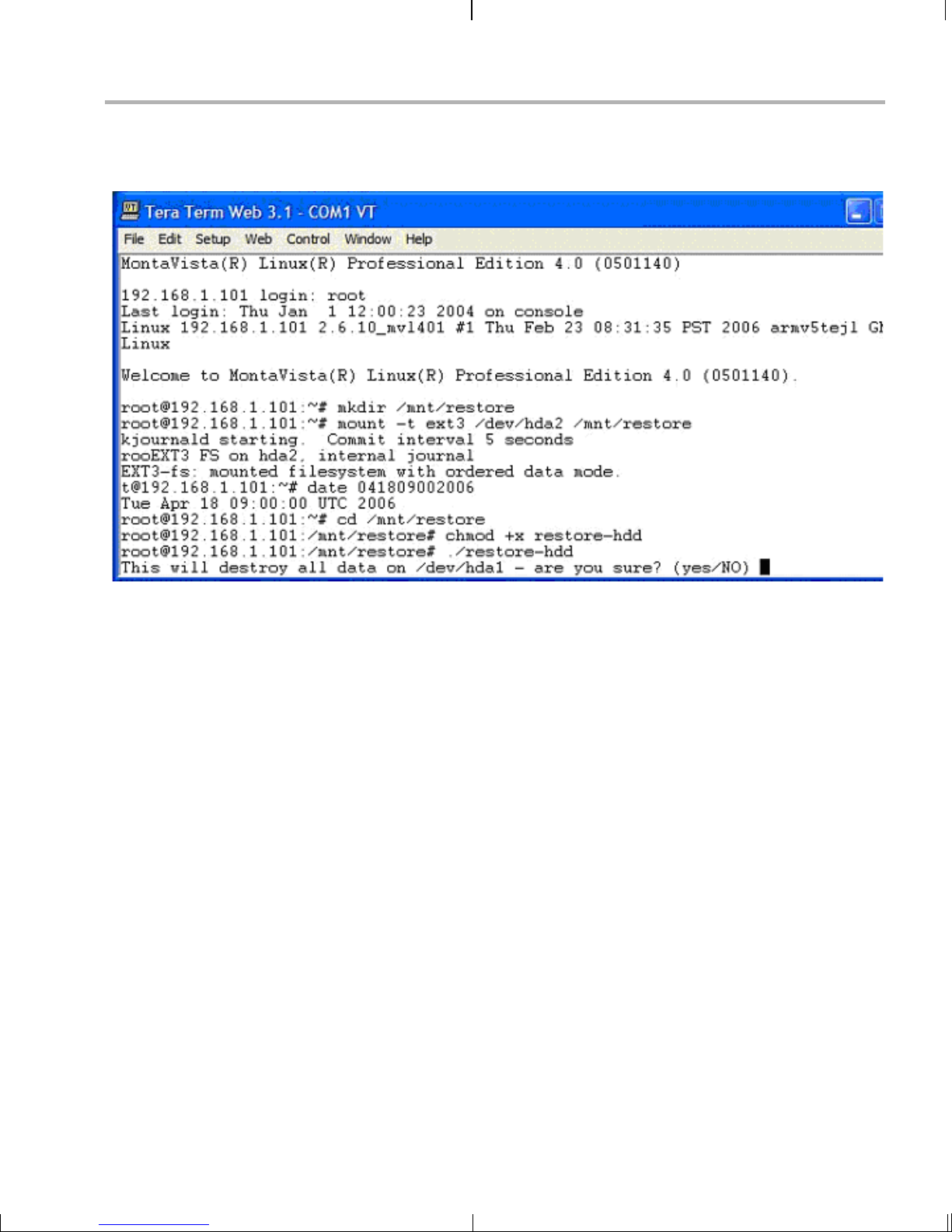
Restoring and Updating the EVM Hard Disk Drive
7) The script will ask for confirmation: "This will destroy all data on
/dev/hda1 - are you sure?" Type yes.
8) After the HDD restore is complete, shutdown the EVM:
EVM # halt
9) When the "Power down" m essag e is print ed in the ter minal window,
it is safe to power down the EVM.
10) Restart the EVM and c onfigure U-Boot to root moun t via the local
HDD. Follow the steps in Section A.4.1, Booting fr om Flash Us ing the
EVM’s Hard Drive File System.
A.6.5 Restoring From Host Linux Workstation File System
This section assumes that you have installed the DVEVM software to the
host Linux /workdir/fil esys/restore di rectory. After an NFS mount, this is
equivalent to /restore for the target EVM.
Follow these steps to restore the HDD from the host Linux workstation
restore directory:
1) On your host workstation, copy the restore directory from the TI
DVSDK disk to /home/<useracct>/workdir/filesys/restore. After NFS
mounting this file system, this will appear as the /restore directory on
the EVM.
2) Login to the EVM as root.
Additional Procedures A-15
Page 70

Restoring and Updating the EVM Hard Disk D rive
3) Go to the /restore directory.
EVM # cd /restore
4) Set the Linux da te variable to to day's date. If the da te is too far off,
the target file system in stallation generat es warnings for each file it
installs.
EVM # date MMDDHHMMCCYY
For example, for 9:00 am on April 18th, 2006, enter 041809002006.
5) Add execute permissions on the prep-hdd script.
EVM # chmod +x prep-hdd
6) Run the prep-hdd script in the /restore directory.
EVM # ./prep-hdd /restore
7) The script will ask for confirmation: "Are you sure you want to
partition and format /dev/hda1?" Type yes.
8) After the HDD restore is complete, shutdown the EVM:
EVM # halt
9) When the "Power down" m essag e is print ed in the ter minal window,
it is safe to power down the EVM.
10) Restart the EVM and c onfigure U-Boot to root moun t via the local
HDD. Follow the steps in Section A.4.1, Booting from Flash Using the
EVM’s Hard Drive File System.
If you instead manually restore the overlay.tar.gz file from disk 1 on an
NFS file syst em, the demos will likely produce a cryp tic error. Although
such manual restores are not documented or recommended, you can
correct the problem by turning off the s-bit as follows:
EVM # cd /opt/dvsdk/dm6446
EVM # chmod u-s ${install}/encode ${install}/decode ${install}/encodedecode \
${install}/interface
A-16
Page 71

Index
A
A/V files 4-8
AAC audio 3-9
application 4-4
ARM9 1-3
arrow buttons 3-4
audio cables 2-3
B
battery 1-4, 3-3
bin files 4-6
BIOS_INSTALL_DIR environment variable 4-16
block diagram 1-4
boot configurations A-8
flash with hard drive A-8
flash with NFS A-10
NFS 4-11
standard 3-2
TFTP with hard drive A-9
TFTP with NFS A-10
boot sequence A-8
build environment 4-13
C
C64+ DSP 1-3
cables 1-3
connecting 2-2
camera 1-3, 2-3
clock battery 1-4
Code Search button 3-3
Codec Engine 3-5, 3-6, 4-4
documentation 4-22
Codegen Tools
documentation 4-21
installation location 4-7
COM port 2-6
command line demos 3-9
command prompts 4-3
component video A-2, A-4
composite video A-2
console window 2-6
contents of kit 1-3
CPU load 3-5
D
data files 4-8
DaVinci technology 1-2
Decode demo 3-4, 3-8
command line 3-10
demos 3-2
command line 3-9
digital camera 1-3
Digital Video Test Bench (DVTB)
building 4-18, 4-21
documentation 4-18, 4-21
directories
installation 4-8
disks
file contents 4-2
mounting 4-5
display 1-3, 2-2
DISPLAY environment variable 4-5
DSP 4-4
DSP/BIOS
documentation 4-21
install ation location 4-7
DSP/BIOS Link 4-4
DVD button 3-3
DVEVM 1-2
installing software 4-7
DVEVM software
rebuilding 4-16
DVSPB 4-3
E
electrostatic precau tion s 2-2
Encode + Decode demo 3-4, 3-6
command line 3-10
Encode demo 3-4, 3-7
command line 3-10
environment variables
Index--1
Page 72

Index
BIOS_INSTALL_DIR 4-16
FC_INSTALL_DIR 4-16
XDC_INSTALL_DIR 4-16
ESD precautions 2-3
Ethernet 2-4
setup 2-5
EVM # prompt 2-6, 4-3
examples 3-2
exit demo 3-5
exports file 4-10
F
FC_INSTA LL_DIR environment v ariable 4-16
file extensions 3-7, 3-9
file system 4-9
video performance 4-9
files
Decode demo 3-8
Encode demo 3-7
on disks 4-2
flash memory
boot configuration A-8, A-10
G
K
kit content s 1-3
L
LCD display 1-3, 2-2
Link, DSP/BIOS 4-4
Linux 4-4
installing 4-6
kernel 4-14
versions supported 4-6
Linux Support Package 4-14
M
microphone 1-3, 2-4
monitor 2-2
MontaVista Linux
demo version 4-3
full version 4-3
MPEG2 video 3-9
MPEG4 video 3-7, 3-9
multimedia peripherals 1-4
G.711 speech 3-7, 3-9
H
H.264 video 3-6, 3-7, 3-9
hard disk drive A-12
hard drive 1-3
boot configuration A-8, A-9
HDD A-12
restore A-12, A-14
host $ prompt 4-3
I
Info/Select button 3-5
installation locati on 4-8
installing
DVEVM software 4-7
hardware 2-2
Linux softw are 4-6
IR remote 1-3, 2-5, 3-3
resetting code 3-3
N
NFS server 4-9
boot configuration A-10
testing 4-11
video performance 4-9
NTSC video 2-2, 4-12
O
OSD show and hide 3-5
OSD toggle 3-5
overlay.tar.gz file A-16
P
PAL video 2-2, 4-12
PATH environment variable 4-13
Pause button 3-5
performance 4-9
peripherals 1-4, 2 -2
Play button 3-5
ports 2-4
power 2-5
Power button 3-5
power cabl e 2-4, 2-5
Index--2
Page 73

Index
prompts 4-3
Q
quit demo 3-5
R
rebuilding
DVEVM software 4-16
Linux kernel 4-14
Record button 3-5
Red Hat Enterprise Linux 4-6
remote control 1-3, 3-3
resetting code 3-3
restore HDD A-12
Rules.make file 4-16
running application s 3-4
S
s-bit A-16
serial cable 2-6
serial connection 2-5
SoC Analyzer 4-2, 4-9
software 4-2
components 1-3, 4-4
installing 4-6
Spectrum Digital website 1-4
standalone demos 3-2
static precautions 2-2
Stop button 3-5
S-Video A-2
input A-2
output A-3
T
target $ prompt 4-3
terminal session 2-6
test program 4-13
TFTP
boot configuration A-9, A-10
server A-7
transfer files to board 4-17
Third-Party Menu 3-4, A-5
TMS320DM6446 1-3
transparency of OSD 3-5
U
U-Boot utility 4-14
uImage boot file 4-17
V
video cable 2-2
video camera 1-3, 2-3
power 2-3
video formats A-2
videostd environment variable 4-12
VISA APIs 4-4
X
xDAIS 4-4
XDC_INSTALL_DIR environment variable 4-16
xDM 4-4
Y
YPrPb A-4
Index--3
Page 74

Index--4
Page 75

Page 76

Spectrum Digital, Inc.
508168-0001C
 Loading...