

Page 1

TMS320DM643x DMP
Universal Asynchronous Receiver/Transmitter
(UART)
User's Guide
Literature Number: SPRU997C
December 2009
Page 2

2
SPRU997C–December 2009
Submit Documentation Feedback
Copyright © 2009, Texas Instruments Incorporated
Page 3

Preface ....................................................................................................................................... 6
1 Introduction ........................................................................................................................ 7
1.1 Purpose of the Peripheral .............................................................................................. 7
1.2 Features .................................................................................................................. 7
1.3 Functional Block Diagram .............................................................................................. 8
1.4 Industry Standard(s) Compliance Statement ........................................................................ 8
2 Peripheral Architecture ...................................................................................................... 10
2.1 Clock Generation and Control ........................................................................................ 10
2.2 Signal Descriptions .................................................................................................... 12
2.3 Pin Multiplexing ........................................................................................................ 12
2.4 Protocol Description ................................................................................................... 12
2.5 Endianness Considerations .......................................................................................... 13
2.6 Operation ................................................................................................................ 14
2.7 Reset Considerations .................................................................................................. 18
2.8 Initialization ............................................................................................................. 18
2.9 Interrupt Support ....................................................................................................... 18
2.10 DMA Event Support ................................................................................................... 20
2.11 Power Management ................................................................................................... 20
2.12 Emulation Considerations ............................................................................................. 20
2.13 Exception Processing ................................................................................................. 21
3 Registers .......................................................................................................................... 21
3.1 Receiver Buffer Register (RBR) ...................................................................................... 22
3.2 Transmitter Holding Register (THR) ................................................................................. 23
3.3 Interrupt Enable Register (IER) ...................................................................................... 24
3.4 Interrupt Identification Register (IIR) ................................................................................ 25
3.5 FIFO Control Register (FCR) ......................................................................................... 26
3.6 Line Control Register (LCR) .......................................................................................... 28
3.7 Modem Control Register (MCR) ..................................................................................... 30
3.8 Line Status Register (LSR) ........................................................................................... 31
3.9 Divisor Latches (DLL and DLH) ...................................................................................... 33
3.10 Peripheral Identification Registers (PID1 and PID2) .............................................................. 35
3.11 Power and Emulation Management Register (PWREMU_MGMT) .............................................. 36
Appendix A Revision History ...................................................................................................... 37
SPRU997C–December 2009 Table of Contents
Submit Documentation Feedback
Copyright © 2009, Texas Instruments Incorporated
3
Page 4

www.ti.com
List of Figures
1 UART Block Diagram....................................................................................................... 9
2 UART Clock Generation Diagram....................................................................................... 10
3 Relationships Between Data Bit, BCLK, and UART Input Clock.................................................... 11
4 UART Protocol Formats .................................................................................................. 13
5 UART Interface Using Autoflow Diagram .............................................................................. 16
6 Autoflow Functional Timing Waveforms for RTS...................................................................... 17
7 Autoflow Functional Timing Waveforms for CTS...................................................................... 17
8 UART Interrupt Request Enable Paths ................................................................................. 19
9 Receiver Buffer Register (RBR) ......................................................................................... 22
10 Transmitter Holding Register (THR) .................................................................................... 23
11 Interrupt Enable Register (IER).......................................................................................... 24
12 Interrupt Identification Register (IIR).................................................................................... 25
13 FIFO Control Register (FCR) ............................................................................................ 27
14 Line Control Register (LCR) ............................................................................................. 28
15 Modem Control Register (MCR)......................................................................................... 30
16 Line Status Register (LSR)............................................................................................... 31
17 Divisor LSB Latch (DLL).................................................................................................. 34
18 Divisor MSB Latch (DLH)................................................................................................. 34
19 Peripheral Identification Register 1 (PID1)............................................................................. 35
20 Peripheral Identification Register 2 (PID2)............................................................................. 35
21 Power and Emulation Management Register (PWREMU_MGMT) ................................................. 36
4
List of Figures SPRU997C–December 2009
Copyright © 2009, Texas Instruments Incorporated
Submit Documentation Feedback
Page 5

www.ti.com
1 UART Supported Features/Characteristics by Instance ............................................................... 8
2 Baud Rate Examples for 27 MHz UART Input Clock................................................................. 11
3 UART Signal Descriptions................................................................................................ 12
4 Character Time for Word Lengths....................................................................................... 15
5 UART Interrupt Requests Descriptions................................................................................. 19
6 UART Registers ........................................................................................................... 21
7 Receiver Buffer Register (RBR) Field Descriptions................................................................... 22
8 Transmitter Holding Register (THR) Field Descriptions.............................................................. 23
9 Interrupt Enable Register (IER) Field Descriptions ................................................................... 24
10 Interrupt Identification Register (IIR) Field Descriptions.............................................................. 25
11 Interrupt Identification and Interrupt Clearing Information............................................................ 26
12 FIFO Control Register (FCR) Field Descriptions ...................................................................... 27
13 Line Control Register (LCR) Field Descriptions ....................................................................... 28
14 Relationship Between ST, EPS, and PEN Bits in LCR............................................................... 29
15 Number of STOP Bits Generated ....................................................................................... 29
16 Modem Control Register (MCR) Field Descriptions................................................................... 30
17 Line Status Register (LSR) Field Descriptions ........................................................................ 31
18 Divisor LSB Latch (DLL) Field Descriptions............................................................................ 34
19 Divisor MSB Latch (DLH) Field Descriptions .......................................................................... 34
20 Peripheral Identification Register 1 (PID1) Field Descriptions....................................................... 35
21 Peripheral Identification Register 2 (PID2) Field Descriptions....................................................... 35
22 Power and Emulation Management Register (PWREMU_MGMT) Field Descriptions........................... 36
23 Document Revision History .............................................................................................. 37
List of Tables
SPRU997C–December 2009 List of Tables
Submit Documentation Feedback
Copyright © 2009, Texas Instruments Incorporated
5
Page 6
About This Manual
This document describes the universal asynchronous receiver/transmitter (UART) peripheral in the
TMS320DM643x Digital Media Processor (DMP) .
Notational Conventions
This document uses the following conventions.
• Hexadecimal numbers are shown with the suffix h. For example, the following number is 40
hexadecimal (decimal 64): 40h.
• Registers in this document are shown in figures and described in tables.
– Each register figure shows a rectangle divided into fields that represent the fields of the register.
Each field is labeled with its bit name, its beginning and ending bit numbers above, and its
read/write properties below. A legend explains the notation used for the properties.
– Reserved bits in a register figure designate a bit that is used for future device expansion.
Related Documentation From Texas Instruments
The following documents describe the TMS320DM643x Digital Media Processor (DMP). Copies of these
documents are available on the Internet at www.ti.com. Tip: Enter the literature number in the search box
provided at www.ti.com.
The current documentation that describes the DM643x DMP, related peripherals, and other technical
collateral, is available in the C6000 DSP product folder at: www.ti.com/c6000.
SPRU978 — TMS320DM643x DMP DSP Subsystem Reference Guide. Describes the digital signal
processor (DSP) subsystem in the TMS320DM643x Digital Media Processor (DMP).
Preface
SPRU997C–December 2009
Read This First
SPRU983 — TMS320DM643x DMP Peripherals Overview Reference Guide. Provides an overview and
briefly describes the peripherals available on the TMS320DM643x Digital Media Processor (DMP).
SPRAA84 — TMS320C64x to TMS320C64x+ CPU Migration Guide. Describes migrating from the
Texas Instruments TMS320C64x digital signal processor (DSP) to the TMS320C64x+ DSP. The
objective of this document is to indicate differences between the two cores. Functionality in the
devices that is identical is not included.
SPRU732 — TMS320C64x/C64x+ DSP CPU and Instruction Set Reference Guide. Describes the CPU
architecture, pipeline, instruction set, and interrupts for the TMS320C64x and TMS320C64x+ digital
signal processors (DSPs) of the TMS320C6000 DSP family. The C64x/C64x+ DSP generation
comprises fixed-point devices in the C6000 DSP platform. The C64x+ DSP is an enhancement of
the C64x DSP with added functionality and an expanded instruction set.
SPRU871 — TMS320C64x+ DSP Megamodule Reference Guide. Describes the TMS320C64x+ digital
signal processor (DSP) megamodule. Included is a discussion on the internal direct memory access
(IDMA) controller, the interrupt controller, the power-down controller, memory protection, bandwidth
management, and the memory and cache.
6
Preface SPRU997C–December 2009
Copyright © 2009, Texas Instruments Incorporated
Submit Documentation Feedback
Page 7

Universal Asynchronous Receiver/Transmitter (UART)
1 Introduction
This document describes the universal asynchronous receiver/transmitter (UART) peripheral in the
TMS320DM643x Digital Media Processor (DMP) .
1.1 Purpose of the Peripheral
The UART peripheral is based on the industry standard TL16C550 asynchronous communications
element, which in turn is a functional upgrade of the TL16C450. Functionally similar to the TL16C450 on
power up (single character or TL16C450 mode), the UART can be placed in an alternate FIFO
(TL16C550) mode. This relieves the CPU of excessive software overhead by buffering received and
transmitted characters. The receiver and transmitter FIFOs store up to 16 bytes including three additional
bits of error status per byte for the receiver FIFO.
The UART performs serial-to-parallel conversions on data received from a peripheral device and
parallel-to-serial conversion on data received from the CPU. The CPU can read the UART status at any
time. The UART includes control capability and a processor interrupt system that can be tailored to
minimize software management of the communications link.
The UART includes a programmable baud generator capable of dividing the UART input clock by divisors
from 1 to 65 535 and producing a 16 × reference clock for the internal transmitter and receiver logic. For
detailed timing and electrical specifications for the UART, see the device specific data manual.
User's Guide
SPRU997C–December 2009
1.2 Features
The UART peripheral has the following features:
• Programmable baud rates up to 128 kbps (frequency pre-scale values from 1 to 65535)
• Fully programmable serial interface characteristics:
– 5, 6, 7, or 8-bit characters
– Even, odd, or no PARITY bit generation and detection
– 1, 1.5, or 2 STOP bit generation
• 16-byte depth transmitter and receiver FIFOs:
– The UART can be operated with or without the FIFOs
– 1, 4, 8, or 14 byte selectable receiver FIFO trigger level for autoflow control and DMA
• DMA signaling capability for both received and transmitted data
• CPU interrupt capability for both received and transmitted data
• Operates in little-endian mode
• False START bit detection
• Line break generation and detection
• Internal diagnostic capabilities:
– Loopback controls for communications link fault isolation
– Break, parity, overrun, and framing error simulation
• Programmable autoflow control using CTS and RTS signals (not supported on all UARTs. See the
device-specific data manual for supported features.)
• Modem control functions using CTS and RTS signals (not supported on all UARTs. See the
device-specific data manual for supported features.)
SPRU997C–December 2009 Universal Asynchronous Receiver/Transmitter (UART)
Submit Documentation Feedback
Copyright © 2009, Texas Instruments Incorporated
7
Page 8

Introduction
Table 1 summarizes the capabilities supported on the UART. Note that the number of UARTs and their
supported features vary on each device, see the device-specific data manual for more details.
Feature Support
5, 6, 7 or 8-bit characters Supported
Even, odd, or no PARITY bit Supported
1, 1.5, or 2 STOP bit generation Supported
Line break generation and detection Supported
Internal loop back Supported
DMA sync events for both received and transmitted data Supported
1, 4, 8, or 14 byte selectable receiver FIFO trigger level Supported
Polling/Interrupt Supported
Max speed 128 kbps Supported
Modem control functions using CTS and RTS Supported
Autoflow control using CTS and RTS Supported
DTR and DSR Not supported
Ring indication Not supported
Carrier detection Not supported
Single-character transfer mode (mode 0) in DMA mode Not supported
(1)
www.ti.com
Table 1. UART Supported Features/Characteristics by Instance
(1)
(1)
Not supported on all UARTs. See the device-specific data manual for supported features.
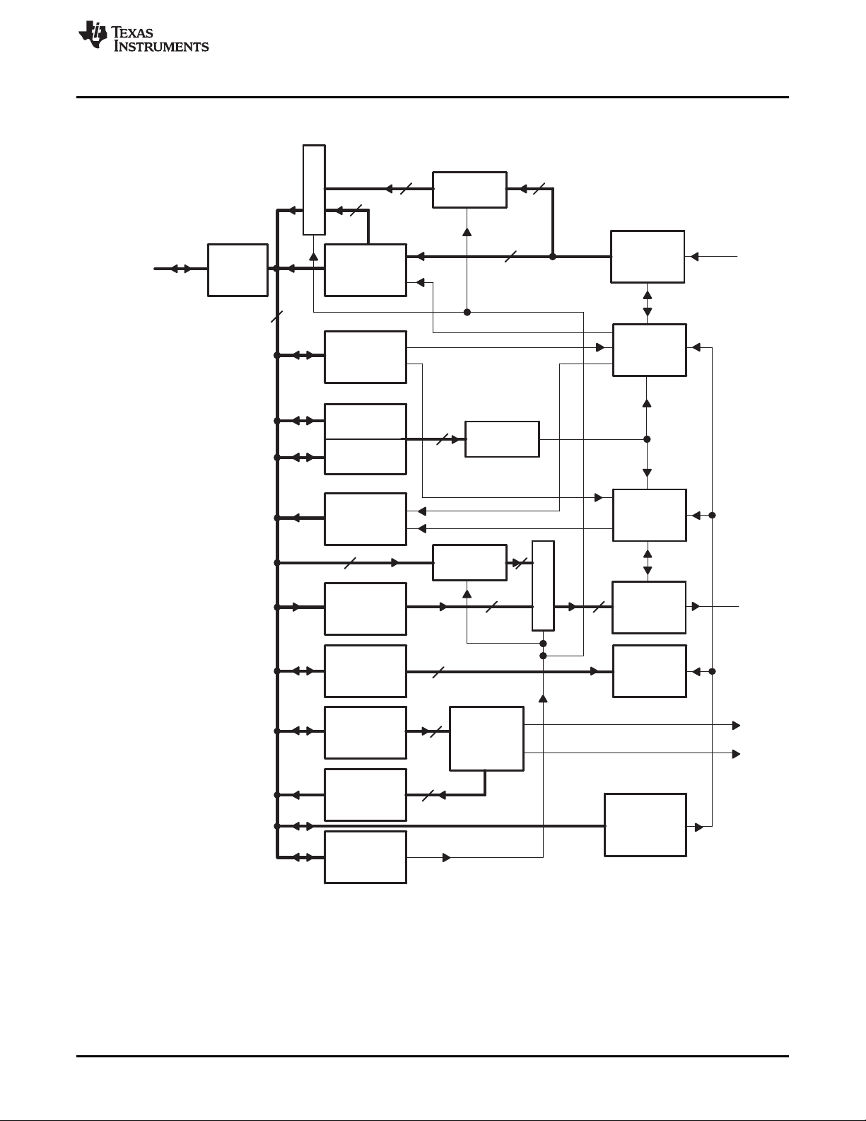
1.3 Functional Block Diagram
A functional block diagram of the UART is shown in Figure 1.
1.4 Industry Standard(s) Compliance Statement
The UART peripheral is based on the industry standard TL16C550 asynchronous communications
element, which is a functional upgrade of the TL16C450. Any deviations in supported functions are
indicated in Table 1.
The information in this document assumes the reader is familiar with these standards.
8
Universal Asynchronous Receiver/Transmitter (UART) SPRU997C–December 2009
Copyright © 2009, Texas Instruments Incorporated
Submit Documentation Feedback
Page 9
8
Receiver
Buffer
Register
Divisor
Latch (LS)
Divisor
Latch (MS)
Baud
Generator
Receiver
FIFO
Line
Status
Register
Transmitter
Holding
Register
Modem
Control
Register
Line
Control
Register
Transmitter
FIFO
Interrupt
Enable
Register
Interrupt
Identification
Register
FIFO
Control
Register
Interrupt/
Event
Control
Logic
S
e
l
e
c
t
Data
Bus
Buffer
RX
TX
Peripheral
Bus
S
e
l
e
c
t
Receiver
Shift
Register
Receiver
Timing and
Control
Transmitter
Timing and
Control
Transmitter
Shift
Register
Control
Logic
16
8
8
8
8
8
Interrupt to CPU
16
8
pin
pin
8
88
8
Power and
Emulation
Control
Register
Event to DMA controller
www.ti.com
Introduction
Figure 1. UART Block Diagram
SPRU997C–December 2009 Universal Asynchronous Receiver/Transmitter (UART)
Submit Documentation Feedback
Copyright © 2009, Texas Instruments Incorporated
9
Page 10
Divisor +
UART input clock frequency
Desired baud rate 16
Processor
generator
Clock
DLH:DLL
UART input clock
DSP input clock
UART
Receiver
timing and
control
Transmitter
timing and
control
Baud
generator
BCLK
Other logic
Peripheral Architecture
2 Peripheral Architecture
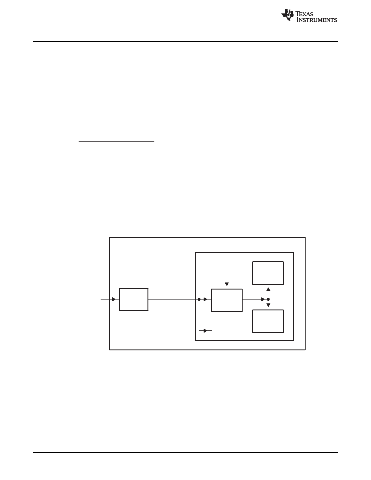
2.1 Clock Generation and Control
The UART bit clock is sourced from the PLLC1 AUXCLK. It supports up to 128 kbps maximum data rate.
Figure 2 is a conceptual clock generation diagram for the UART. The processor clock generator receives
a signal from an external clock source and produces a UART input clock with a programmed frequency.
The UART contains a programmable baud generator that takes an input clock and divides it by a divisor in
the range between 1 and (216- 1) to produce a baud clock (BCLK). The frequency of BCLK is sixteen
times (16 ×) the baud rate; each received or transmitted bit lasts 16 BCLK cycles. When the UART is
receiving, the bit is sampled in the 8th BCLK cycle. The formula to calculate the divisor is:
Two 8-bit register fields (DLH and DLL), called divisor latches, hold this 16-bit divisor. DLH holds the most
significant bits of the divisor, and DLL holds the least significant bits of the divisor. For information about
these register fields, see Section 3. These divisor latches must be loaded during initialization of the UART
in order to ensure desired operation of the baud generator. Writing to the divisor latches results in two wait
states being inserted during the write access while the baud generator is loaded with the new value.
Figure 3 summarizes the relationship between the transferred data bit, BCLK, and the UART input clock.
Example baud rates and divisor values relative to a 27-MHz UART input clock are shown in Table 2.
www.ti.com
(1)
Figure 2. UART Clock Generation Diagram
10
Universal Asynchronous Receiver/Transmitter (UART) SPRU997C–December 2009
Copyright © 2009, Texas Instruments Incorporated
Submit Documentation Feedback
Page 11
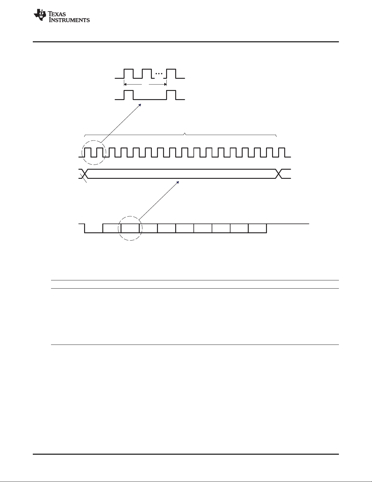
BCLK
Each bit lasts 16 BCLK cycles.
When receiving, the UART samples the bit in the 8th cycle.
D0
TX,
RX
D1 D2
PARITY
D7D6D5
STOP2STOP1
D1 D4D2 D3
START
D0
TX,
RX
UART input clock
n UART input clock cycles, where n = divisor in DLH:DLL
n
BCLK
www.ti.com
Peripheral Architecture
Figure 3. Relationships Between Data Bit, BCLK, and UART Input Clock
Table 2. Baud Rate Examples for 27 MHz UART Input Clock
Baud Rate Divisor Value Actual Baud Rate Error (%)
2400 703 2400.427 0.018
4800 352 4794.034 -0.124
9600 176 9588.068 -0.124
19200 88 19176.14 -0.124
38400 44 38352.27 -0.124
56000 30 56250 0.446
128000 13 129807.7 1.412
SPRU997C–December 2009 Universal Asynchronous Receiver/Transmitter (UART)
Submit Documentation Feedback
Copyright © 2009, Texas Instruments Incorporated
11
Page 12

Peripheral Architecture
2.2 Signal Descriptions
The UARTs utilize a minimal number of signal connections to interface with external devices. The UART
signal descriptions are included in Table 3. Note that the number of UARTs and their supported features
vary on each device, see the device-specific data manual for more details.
Signal Name
UTXDn Output Serial data transmit
URXDn Input Serial data receive
UCTSn Input Clear-to-Send handshaking signal
URTSn Output Request-to-Send handshaking signal
(1)
The value n indicates the applicable UART; that is, UART0, UART1, etc.
(1)
Signal Type Function
2.3 Pin Multiplexing
On the DM643x DMP extensive pin multiplexing is used to accommodate the largest number of peripheral
functions in the smallest possible package. Pin multiplexing is controlled using a combination of hardware
configuration at device reset and software programmable register settings. Refer to the device-specific
data manual to determine how pin multiplexing affects the UART.
2.4 Protocol Description
www.ti.com
Table 3. UART Signal Descriptions
2.4.1 Transmission
The UART transmitter section includes a transmitter hold register (THR) and a transmitter shift register
(TSR). When the UART is in the FIFO mode, THR is a 16-byte FIFO. Transmitter section control is a
function of the UART line control register (LCR). Based on the settings chosen in LCR, the UART
transmitter sends the following to the receiving device:
• 1 START bit
• 5, 6, 7, or 8 data bits
• 1 PARITY bit (optional)
• 1, 1.5, or 2 STOP bits
2.4.2 Reception
The UART receiver section includes a receiver shift register (RSR) and a receiver buffer register (RBR).
When the UART is in the FIFO mode, RBR is a 16-byte FIFO. Receiver section control is a function of the
UART line control register (LCR). Based on the settings chosen in LCR, the UART receiver accepts the
following from the transmitting device:
• 1 START bit
• 5, 6, 7, or 8 data bits
• 1 PARITY bit (optional)
• 1 STOP bit (any other STOP bits transferred with the above data are not detected)
12
Universal Asynchronous Receiver/Transmitter (UART) SPRU997C–December 2009
Submit Documentation Feedback
Copyright © 2009, Texas Instruments Incorporated
Page 13

www.ti.com
2.4.3 Data Format
The UART transmits in the following format:
1 START bit + data bits (5, 6, 7, 8) + 1 PARITY bit (optional) + STOP bit (1, 1.5, 2)
It transmits 1 START bit; 5, 6, 7, or 8 data bits, depending on the data width selection; 1 PARITY bit, if
parity is selected; and 1, 1.5, or 2 STOP bits, depending on the STOP bit selection.
The UART receives in the following format:
1 START bit + data bits (5, 6, 7, 8) + 1 PARITY bit (optional) + STOP bit (1)
It receives 1 START bit; 5, 6, 7, or 8 data bits, depending on the data width selection; 1 PARITY bit, if
parity is selected; and 1 STOP bit.
The protocol formats are shown in Figure 4
Peripheral Architecture
Figure 4. UART Protocol Formats
D0 D1 D2 D3 D4 PARITY STOP1
Transmit/Receive for 5-bit data, parity Enable, 1 STOP bit
D0 D1 D2 D3 D4 D5 PARITY STOP1
Transmit/Receive for 6-bit data, parity Enable, 1 STOP bit
D0 D1 D2 D3 D4 D5 D6 PARITY STOP1
Transmit/Receive for 7-bit data, parity Enable, 1 STOP bit
D0 D1 D2 D3 D4 D5 D6 D7 PARITY STOP1
Transmit/Receive for 8-bit data, parity Enable, 1 STOP bit
2.5 Endianness Considerations
Since the UART transfers 8-bit data externally, and proper endianness is maintained automatically within
the DM643x DMP, there are no endianness considerations when using the DM643x UART peripheral.
SPRU997C–December 2009 Universal Asynchronous Receiver/Transmitter (UART)
Submit Documentation Feedback
Copyright © 2009, Texas Instruments Incorporated
13
Page 14

Peripheral Architecture
2.6 Operation
2.6.1 Transmission
The UART transmitter section includes a transmitter hold register (THR) and a transmitter shift register
(TSR). When the UART is in the FIFO mode, THR is a 16-byte FIFO. Transmitter section control is a
function of the UART line control register (LCR). Based on the settings chosen in LCR, the UART
transmitter sends the following to the receiving device:
• 1 START bit
• 5, 6, 7, or 8 data bits
• 1 PARITY bit (optional)
• 1, 1.5, or 2 STOP bits
THR receives data from the internal data bus, and when TSR is ready, the UART moves the data from
THR to TSR. The UART serializes the data in TSR and transmits the data on the TX pin. In the non-FIFO
mode, if THR is empty and the THR empty interrupt is enabled in the interrupt enable register (IER), an
interrupt is generated. This interrupt is cleared when a character is loaded into THR. In the FIFO mode,
the interrupt is generated when the transmitter FIFO is empty, and it is cleared when at least one byte is
loaded into the FIFO.
2.6.2 Reception
The UART receiver section includes a receiver shift register (RSR) and a receiver buffer register (RBR).
When the UART is in the FIFO mode, RBR is a 16-byte FIFO. Timing is supplied by the 16× receiver
clock. Receiver section control is a function of the UART line control register (LCR). Based on the settings
chosen in LCR, the UART receiver accepts the following from the transmitting device:
• 1 START bit
• 5, 6, 7, or 8 data bits
• 1 PARITY bit (optional)
• 1 STOP bit (any other STOP bits transferred with the above data are not detected)
RSR receives the data bits from the RX pin. Then RSR concatenates the data bits and moves the
resulting value into RBR (or the receiver FIFO). The UART also stores three bits of error status
information next to each received character, to record a parity error, framing error, or break.
In the non-FIFO mode, when a character is placed in RBR and the receiver data-ready interrupt is enabled
in the interrupt enable register (IER), an interrupt is generated. This interrupt is cleared when the character
is read from RBR. In the FIFO mode, the interrupt is generated when the FIFO is filled to the trigger level
selected in the FIFO control register (FCR), and it is cleared when the FIFO contents drop below the
trigger level.
www.ti.com
14
Universal Asynchronous Receiver/Transmitter (UART) SPRU997C–December 2009
Submit Documentation Feedback
Copyright © 2009, Texas Instruments Incorporated
Page 15

www.ti.com
2.6.3 FIFO Modes
The following two modes can be used for servicing the receiver and transmitter FIFOs:
• FIFO interrupt mode. The FIFO is enabled and the associated interrupts are enabled. Interrupts are
sent to the CPU to indicate when specific events occur.
• FIFO poll mode. The FIFO is enabled but the associated interrupts are disabled. The CPU polls status
bits to detect specific events.
Because the receiver FIFO and the transmitter FIFO are controlled separately, either one or both can be
placed into the interrupt mode or the poll mode.
2.6.3.1 FIFO Interrupt Mode
When the receiver FIFO is enabled in the FIFO control register (FCR) and the receiver interrupts are
enabled in the interrupt enable register (IER), the interrupt mode is selected for the receiver FIFO. The
following are important points about the receiver interrupts:
• The receiver data-ready interrupt is issued to the CPU when the FIFO has reached the trigger level
that is programmed in FCR. It is cleared when the CPU or the DMA controller reads enough characters
from the FIFO such that the FIFO drops below its programmed trigger level.
• The receiver line status interrupt is generated in response to an overrun error, a parity error, a framing
error, or a break. This interrupt has higher priority than the receiver data-ready interrupt. For details,
see Section 2.9.
• The data-ready (DR) bit in the line status register (LSR) indicates the presence or absence of
characters in the receiver FIFO. The DR bit is set when a character is transferred from the receiver
shift register (RSR) to the empty receiver FIFO. The DR bit remains set until the FIFO is empty again.
• A receiver time-out interrupt occurs if all of the following conditions exist:
– At least one character is in the FIFO,
– The most recent character was received more than four continuous character times ago. A
character time is the time allotted for 1 START bit, n data bits, 1 PARITY bit, and 1 STOP bit,
where n depends on the word length selected with the WLS bits in the line control register (LCR).
See Table 4.
– The most recent read of the FIFO has occurred more than four continuous character times before.
• Character times are calculated by using the baud rate.
• When a receiver time-out interrupt has occurred, it is cleared and the time-out timer is cleared when
the CPU or the EDMA controller reads one character from the receiver FIFO. The interrupt is also
cleared if a new character is received in the FIFO or if the URRST bit is cleared in the power and
emulation management register (PWREMU_MGMT).
• If a receiver time-out interrupt has not occurred, the time-out timer is cleared after a new character is
received or after the CPU or EDMA reads the receiver FIFO.
When the transmitter FIFO is enabled in FCR and the transmitter holding register empty interrupt is
enabled in IER, the interrupt mode is selected for the transmitter FIFO. The transmitter holding register
empty interrupt occurs when the transmitter FIFO is empty. It is cleared when the transmitter hold register
(THR) is loaded (1 to 16 characters may be written to the transmitter FIFO while servicing this interrupt).
Peripheral Architecture
Table 4. Character Time for Word Lengths
Word Length (n) Character Time Four Character Times
5 Time for 8 bits Time for 32 bits
6 Time for 9 bits Time for 36 bits
7 Time for 10 bits Time for 40 bits
8 Time for 11 bits Time for 44 bits
SPRU997C–December 2009 Universal Asynchronous Receiver/Transmitter (UART)
Submit Documentation Feedback
Copyright © 2009, Texas Instruments Incorporated
15
Page 16

rts
Receiver
FIFO
D[7:0]
UART
Serial to
Parallel
Flow
Control
Transmitter
FIFO
Parallel to
Serial
Flow
Control
Parallel to
Serial
Flow
Control
Serial to
Parallel
Flow
Control
UART
Transmitter
FIFO
Receiver
FIFO
D[7:0]
DMP Off-chip
tx
cts
rx
rx
rts
tx
cts
Peripheral Architecture
2.6.3.2 FIFO Poll Mode
When the receiver FIFO is enabled in the FIFO control register (FCR) and the receiver interrupts are
disabled in the interrupt enable register (IER), the poll mode is selected for the receiver FIFO. Similarly,
when the transmitter FIFO is enabled and the transmitter interrupts are disabled, the transmitted FIFO is in
the poll mode. In the poll mode, the CPU detects events by checking bits in the line status register (LSR):
• The RXFIFOE bit indicates whether there are any errors in the receiver FIFO.
• The TEMT bit indicates that both the transmitter holding register (THR) and the transmitter shift
register (TSR) are empty.
• The THRE bit indicates when THR is empty.
• The BI (break), FE (framing error), PE (parity error), and OE (overrun error) bits specify which error or
errors have occurred.
• The DR (data-ready) bit is set as long as there is at least one byte in the receiver FIFO.
Also, in the FIFO poll mode:
• The interrupt identification register (IIR) is not affected by any events because the interrupts are
disabled.
• The UART does not indicate when the receiver FIFO trigger level is reached or when a receiver
time-out occurs.
2.6.4 Autoflow Control
The UART can employ autoflow control by connecting the CTS and RTS signals. Note that all UARTs do
not support autoflow control, see the device-specific data manual for supported features. The CTS input
must be active before the transmitter FIFO can transmit data. The RTS becomes active when the receiver
needs more data and notifies the sending device. When RTS is connected to CTS, data transmission
does not occur unless the receiver FIFO has space for the data. Therefore, when two UARTs are
connected as shown in Figure 5 with autoflow enabled, overrun errors are eliminated.
www.ti.com
16
Universal Asynchronous Receiver/Transmitter (UART) SPRU997C–December 2009
Figure 5. UART Interface Using Autoflow Diagram
Copyright © 2009, Texas Instruments Incorporated
Submit Documentation Feedback
Page 17

RX
RTS
Start Start StartStopStop
Bits N
Bits N+1
Start Stop
TX
CTS
Start StopBits0−7 Start StopBits 0−7 Start StopBits 0−7
www.ti.com
2.6.4.1 RTS Behavior
RTS data flow control originates in the receiver block (see Figure 1). When the receiver FIFO level
reaches a trigger level of 1, 4, 8, or 14 (see Figure 6), RTS is deasserted. The sending UART may send
an additional byte after the trigger level is reached (assuming the sending UART has another byte to
send), because it may not recognize the deassertion of RTS until after it has begun sending the additional
byte. For trigger level 1, 4, and 8, RTS is automatically reasserted once the receiver FIFO is emptied. For
trigger level 14, RTS is automatically reasserted once the receiver FIFO drops below the trigger level.
(1) N = Receiver FIFO trigger level.
(2) The two blocks in dashed lines cover the case where an additional byte is sent.
2.6.4.2 CTS Behavior
The transmitter checks CTS before sending the next data byte. If CTS is active, the transmitter sends the
next byte. To stop the transmitter from sending the following byte, CTS must be released before the
middle of the last STOP bit that is currently being sent (see Figure 7). When flow control is enabled, CTS
level changes do not trigger interrupts because the device automatically controls its own transmitter.
Without autoflow control, the transmitter sends any data present in the transmitter FIFO and a receiver
overrun error may result.
Peripheral Architecture
Figure 6. Autoflow Functional Timing Waveforms for RTS
Figure 7. Autoflow Functional Timing Waveforms for CTS
(1) When CTS is active (low), the transmitter keeps sending serial data out.
(2) When CTS goes high before the middle of the last STOP bit of the current byte, the transmitter finishes
sending the current byte but it does not send the next byte.
(3) When CTS goes from high to low, the transmitter begins sending data again.
2.6.5 Loopback Control
The UART can be placed in the diagnostic mode using the LOOP bit in the modem control register (MCR),
which internally connects the UART output back to the UART input. In this mode, the transmit and receive
data paths, the transmitter and receiver interrupts, and the modem control interrupts can be verified
without connecting to another UART.
SPRU997C–December 2009 Universal Asynchronous Receiver/Transmitter (UART)
Submit Documentation Feedback
Copyright © 2009, Texas Instruments Incorporated
17
Page 18

Peripheral Architecture
2.7 Reset Considerations
2.7.1 Software Reset Considerations
Two bits in the power and emulation management register (PWREMU_MGMT) control resetting the parts
of the UART:
• The UTRST bit controls resetting the transmitter only. If UTRST = 1, the transmitter is active;
if UTRST = 0, the transmitter is in reset.
• The URRST bit controls resetting the receiver only. If URRST = 1, the receiver is active;
if URRST = 0, the receiver is in reset.
In each case, putting the receiver and/or transmitter in reset will reset the state machine of the affected
portion but does not affect the UART registers.
2.7.2 Hardware Reset Considerations
When the processor RESET pin is asserted, the entire processor is reset and is held in the reset state
until the RESET pin is released. As part of a device reset, the UART state machine is reset and the UART
registers are forced to their default states. The default states of the registers are shown in Section 3.
2.8 Initialization
The following steps are required to initialize the UART:
1. Perform the necessary device pin multiplexing setup (see the device-specific data manual).
2. Program the VDD3P3V_PWDN register to power up the IO pins for the UART (see the device-specific
data manual).
3. Set the desired baud rate by writing the appropriate clock divisor values to the divisor latch registers
(DLL and DLH).
4. If the FIFOs will be used, select the desired trigger level and enable the FIFOs by writing the
appropriate values to the FIFO control register (FCR). The FIFOEN bit in FCR must be set first, before
the other bits in FCR are configured.
5. Choose the desired protocol settings by writing the appropriate values to the line control register
(LCR).
6. If autoflow control is desired, write appropriate values to the modem control register (MCR). Note that
all UARTs do not support autoflow control, see the device-specific data manual for supported features.
7. Choose the desired response to emulation suspend events by configuring the FREE bit and enable the
UART by setting the UTRST and URRST bits in the power and emulation management register
(PWREMU_MGMT).
www.ti.com
2.9 Interrupt Support
2.9.1 Interrupt Events and Requests
The UART generates the interrupt requests described in Table 5. All requests are multiplexed through an
arbiter to a single UART interrupt request to the CPU, as shown in Figure 8. Each of the interrupt requests
has an enable bit in the interrupt enable register (IER) and is recorded in the interrupt identification
register (IIR).
If an interrupt occurs and the corresponding enable bit is set to 1, the interrupt request is recorded in IIR
and is forwarded to the CPU. If an interrupt occurs and the corresponding enable bit is cleared to 0, the
interrupt request is blocked. The interrupt request is neither recorded in IIR nor forwarded to the CPU.
2.9.2 Interrupt Multiplexing
The UARTs have dedicated interrupt signals to the DSP CPU and the interrupts are not multiplexed with
any other interrupt source.
18
Universal Asynchronous Receiver/Transmitter (UART) SPRU997C–December 2009
Copyright © 2009, Texas Instruments Incorporated
Submit Documentation Feedback
Page 19

UART interrupt
request to CPU
IER(ETBEI)
IER(ERBI)
Transmitter holding
register empty
Receiver data ready
THREINT
RDRINT
Overrun error
IER(ELSI)
RTOINT
Conditions Enable bits UART interrupt requests
Arbiter
Parity error
Framing error
Break
RLSINT
Receiver time-out
www.ti.com
Peripheral Architecture
Table 5. UART Interrupt Requests Descriptions
UART Interrupt
Request Interrupt Source Comment
THREINT THR-empty condition: The transmitter holding register If THREINT is enabled in IER, by setting the ETBEI
(THR) or the transmitter FIFO is empty. All of the data bit, it is recorded in IIR.
has been copied from THR to the transmitter shift As an alternative to using THREINT, the CPU can poll
register (TSR). the THRE bit in the line status register (LSR).
RDAINT Receive data available in non-FIFO mode or trigger If RDAINT is enabled in IER, by setting the ERBI bit,
level reached in the FIFO mode. it is recorded in IIR.
As an alternative to using RDAINT, the CPU can poll
the DR bit in the line status register (LSR). In the
FIFO mode, this is not a functionally equivalent
alternative because the DR bit does not respond to
the FIFO trigger level. The DR bit only indicates the
presence or absence of unread characters.
RTOINT Receiver time-out condition (in the FIFO mode only): The receiver time-out interrupt prevents the UART
No characters have been removed from or input to from waiting indefinitely, in the case when the receiver
the receiver FIFO during the last four character times FIFO level is below the trigger level and thus does not
(see Table 4), and there is at least one character in generate a receiver data-ready interrupt.
the receiver FIFO during this time. If RTOINT is enabled in IER, by setting the ERBI bit,
it is recorded in IIR.
There is no status bit to reflect the occurrence of a
time-out condition.
RLSINT Receiver line status condition: An overrun error, parity If RLSINT is enabled in IER, by setting the ELSI bit, it
error, framing error, or break has occurred. is recorded in IIR.
As an alternative to using RLSINT, the CPU can poll
the following bits in the line status register (LSR):
overrun error indicator (OE), parity error indicator
(PE), framing error indicator (FE), and break indicator
(BI).
Figure 8. UART Interrupt Request Enable Paths
SPRU997C–December 2009 Universal Asynchronous Receiver/Transmitter (UART)
Submit Documentation Feedback
Copyright © 2009, Texas Instruments Incorporated
19
Page 20

Peripheral Architecture
2.10 DMA Event Support
In the FIFO mode, the UART generates the following two DMA events:
• Receive event (URXEVT): The trigger level for the receiver FIFO (1, 4, 8, or 14 characters) is set with
the RXFIFTL bit in the FIFO control register (FCR). Every time the trigger level is reached or a receiver
time-out occurs, the UART sends a receive event to the EDMA controller. In response, the EDMA
controller reads the data from the receiver FIFO by way of the receiver buffer register (RBR). Note that
the receive event is not asserted if the data at the top of the receiver FIFO is erroneous even if the
trigger level has been reached.
• Transmit event (UTXEVT): When the transmitter FIFO is empty (when the last byte in the transmitter
FIFO has been copied to the transmitter shift register), the UART sends an UTXEVT signal to the
EDMA controller. In response, the EDMA controller refills the transmitter FIFO by way of the transmitter
holding register (THR). The UTXEVT signal is also sent to the DMA controller when the UART is taken
out of reset using the UTRST bit in the power and emulation management register
(PWREMU_MGMT).
Activity in DMA channels can be synchronized to these events. In the non-FIFO mode, the UART
generates no DMA events. Any DMA channel synchronized to either of these events must be enabled at
the time the UART event is generated. Otherwise, the DMA channel will miss the event and, unless the
UART generates a new event, no data transfer will occur.
2.11 Power Management
The UART peripheral can be placed in reduced-power modes to conserve power during periods of low
activity. The power management of the UART peripheral is controlled by the processor Power and Sleep
Controller (PSC). The PSC acts as a master controller for power management for all of the peripherals on
the device. For detailed information on power management procedures using the PSC, see the
TMS320DM643x DMP DSP Subsystem Reference Guide (SPRU978).
www.ti.com
2.12 Emulation Considerations
The FREE bit in the power and emulation management register (PWREMU_MGMT) determines how the
UART responds to an emulation suspend event such as an emulator halt or breakpoint. If FREE = 0 and a
transmission is in progress, the UART halts after completing the one-word transmission; if FREE = 0 and
a transmission is not in progress, the UART halts immediately. If FREE = 1, the UART does not halt and
continues operating normally.
Note also that emulator accesses are essentially transparent to UART operation. Emulator read
operations do not affect any register contents, status bits, or operating states. Emulator writes, however,
may affect register contents and may affect UART operation, depending on what register is accessed and
what value is written.
The UART registers can be read from or written to during emulation suspend events, even if the UART
activity has stopped.
20
Universal Asynchronous Receiver/Transmitter (UART) SPRU997C–December 2009
Submit Documentation Feedback
Copyright © 2009, Texas Instruments Incorporated
Page 21

www.ti.com
2.13 Exception Processing
2.13.1 Divisor Latch Not Programmed
Since the processor reset signal has no effect on the divisor latch, the divisor latch will have an unknown
value after power up. If the divisor latch is not programmed after power up, the baud clock (BCLK) will not
operate and will instead be set to a constant logic 1 state.
The divisor latch values should always be reinitialized following a processor reset.
2.13.2 Changing Operating Mode During Busy Serial Communication
Since the serial link characteristics are based on how the control registers are programmed, the UART will
expect the control registers to be static while it is busy engaging in a serial communication. Therefore,
changing the control registers while the module is still busy communicating with another serial device will
most likely cause an error condition and should be avoided.
3 Registers
The system programmer has access to and control over any of the UART registers that are listed in
Table 6. These registers, which control UART operations, receive data, and transmit data, are available at
32-bit addresses in the device memory map. See the device-specific data manual for the memory address
of these registers.
• RBR, THR, and DLL share one address. When the DLAB bit in LCR is 0, reading from the address
gives the content of RBR, and writing to the address modifies THR. When DLAB = 1, all accesses at
the address read or modify DLL. DLL can also be accessed with address offset 20h.
• IER and DLH share one address. When DLAB = 0, all accesses read or modify IER. When DLAB = 1,
all accesses read or modify DLH. DLH can also be accessed with address offset 24h.
• IIR and FCR share one address. Regardless of the value of the DLAB bit, reading from the address
gives the content of IIR, and writing modifies FCR.
Registers
Table 6. UART Registers
Offset Acronym Register Description Section
0h RBR Receiver Buffer Register (read only) Section 3.1
0h THR Transmitter Holding Register (write only) Section 3.2
4h IER Interrupt Enable Register Section 3.3
8h IIR Interrupt Identification Register (read only) Section 3.4
8h FCR FIFO Control Register (write only) Section 3.5
Ch LCR Line Control Register Section 3.6
10h MCR Modem Control Register Section 3.7
14h LSR Line Status Register Section 3.8
20h DLL Divisor LSB Latch Section 3.9
24h DLH Divisor MSB Latch Section 3.9
28h PID1 Peripheral Identification Register 1 Section 3.10
2Ch PID2 Peripheral Identification Register 2 Section 3.10
30h PWREMU_MGMT Power and Emulation Management Register Section 3.11
SPRU997C–December 2009 Universal Asynchronous Receiver/Transmitter (UART)
Submit Documentation Feedback
Copyright © 2009, Texas Instruments Incorporated
21
Page 22

Registers
www.ti.com
3.1 Receiver Buffer Register (RBR)
The receiver buffer register (RBR) is shown in Figure 9 and described in Table 7.
The UART receiver section consists of a receiver shift register (RSR) and a receiver buffer register (RBR).
When the UART is in the FIFO mode, RBR is a 16-byte FIFO. Timing is supplied by the 16x receiver
clock. Receiver section control is a function of the line control register (LCR).
RSR receives serial data from the RX pin. Then RSR concatenates the data and moves it into RBR (or the
receiver FIFO). In the non-FIFO mode, when a character is placed in RBR and the receiver data-ready
interrupt is enabled (DR = 1 in IER), an interrupt is generated. This interrupt is cleared when the character
is read from RBR. In the FIFO mode, the interrupt is generated when the FIFO is filled to the trigger level
selected in the FIFO control register (FCR), and it is cleared when the FIFO contents drop below the
trigger level.
Access considerations:
RBR, THR, and DLL share one address. To read RBR, write 0 to the DLAB bit in LCR, and read from the
shared address. When DLAB = 0, writing to the shared address modifies THR. When DLAB = 1, all
accesses at the shared address read or modify DLL.
DLL also has a dedicated address. If you use the dedicated address, you can keep DLAB = 0, so that
RBR and THR are always selected at the shared address.
Figure 9. Receiver Buffer Register (RBR)
31 16
Reserved
R-0
15 8 7 0
Reserved DATA
R-0 R-0
LEGEND: R = Read only; -n = value after reset
Table 7. Receiver Buffer Register (RBR) Field Descriptions
Bit Field Value Description
31-8 Reserved 0 Reserved
7-0 DATA 0-FFh Received data
22
Universal Asynchronous Receiver/Transmitter (UART) SPRU997C–December 2009
Submit Documentation Feedback
Copyright © 2009, Texas Instruments Incorporated
Page 23

www.ti.com
3.2 Transmitter Holding Register (THR)
The transmitter holding register (THR) is shown in Figure 10 and described in Table 8.
The UART transmitter section consists of a transmitter hold register (THR) and a transmitter shift register
(TSR). When the UART is in the FIFO mode, THR is a 16-byte FIFO. Transmitter section control is a
function of the line control register (LCR).
THR receives data from the internal data bus and when TSR is idle, the UART moves the data from THR
to TSR. The UART serializes the data in TSR and transmits the data on the TX pin. In the non-FIFO
mode, if THR is empty and the THR empty (THRE) interrupt is enabled (ETBEI = 1 in IER), an interrupt is
generated. This interrupt is cleared when a character is loaded into THR. In the FIFO mode, the interrupt
is generated when the transmitter FIFO is empty, and it is cleared when at least one byte is loaded into
the FIFO.
Access considerations:
RBR, THR, and DLL share one address. To load THR, write 0 to the DLAB bit of LCR, and write to the
shared address. When DLAB = 0, reading from the shared address gives the content of RBR. When
DLAB = 1, all accesses at the address read or modify DLL.
DLL also has a dedicated address. If you use the dedicated address, you can keep DLAB = 0, so that
RBR and THR are always selected at the shared address.
Figure 10. Transmitter Holding Register (THR)
31 16
Reserved
R-0
15 8 7 0
Reserved DATA
R-0 W-0
LEGEND: R = Read only; W = Write only; -n = value after reset
Registers
Table 8. Transmitter Holding Register (THR) Field Descriptions
Bit Field Value Description
31-8 Reserved 0 Reserved
7-0 DATA 0-FFh Data to transmit
SPRU997C–December 2009 Universal Asynchronous Receiver/Transmitter (UART)
Submit Documentation Feedback
Copyright © 2009, Texas Instruments Incorporated
23
Page 24

Registers
www.ti.com
3.3 Interrupt Enable Register (IER)
The interrupt enable register (IER) is used to individually enable or disable each type of interrupt request
that can be generated by the UART. Each interrupt request that is enabled in IER is forwarded to the
CPU. IER is shown in Figure 11 and described in Table 9.
Access considerations:
IER and DLH share one address. To read or modify IER, write 0 to the DLAB bit in LCR. When DLAB = 1,
all accesses at the shared address read or modify DLH.
DLH also has a dedicated address. If you use the dedicated address, you can keep DLAB = 0, so that IER
is always selected at the shared address.
Figure 11. Interrupt Enable Register (IER)
31 16
Reserved
R-0
15 4 3 2 1 0
Reserved Rsvd ELSI ETBEI ERBI
R-0 R/W-0 R/W-0 R/W-0 R/W-0
LEGEND: R/W = Read/Write; R = Read only; -n = value after reset
Table 9. Interrupt Enable Register (IER) Field Descriptions
Bit Field Value Description
31-4 Reserved 0 Reserved
3 Reserved 0 Reserved. This bit must always be written with a 0.
2 ELSI Receiver line status interrupt enable.
0 Receiver line status interrupt is disabled.
1 Receiver line status interrupt is enabled.
1 ETBEI Transmitter holding register empty interrupt enable.
0 Transmitter holding register empty interrupt is disabled.
1 Transmitter holding register empty interrupt is enabled.
0 ERBI Receiver data available interrupt and character timeout indication interrupt enable.
0 Receiver data available interrupt and character timeout indication interrupt is disabled.
1 Receiver data available interrupt and character timeout indication interrupt is enabled.
24
Universal Asynchronous Receiver/Transmitter (UART) SPRU997C–December 2009
Submit Documentation Feedback
Copyright © 2009, Texas Instruments Incorporated
Page 25

www.ti.com
3.4 Interrupt Identification Register (IIR)
The interrupt identification register (IIR) is a read-only register at the same address as the FIFO control
register (FCR), which is a write-only register. When an interrupt is generated and enabled in the interrupt
enable register (IER), IIR indicates that an interrupt is pending in the IPEND bit and encodes the type of
interrupt in the INTID bits. IIR is shown in Figure 12 and described in Figure 12.
The UART has an on-chip interrupt generation and prioritization capability that permits flexible
communication with the CPU. The UART provides three priority levels of interrupts:
• Priority 1 - Receiver line status (highest priority)
• Priority 2 - Receiver data ready or receiver timeout
• Priority 3 - Transmitter holding register empty
The FIFOEN bit in IIR can be checked to determine whether the UART is in the FIFO mode or the
non-FIFO mode.
Access consideration:
IIR and FCR share one address. Regardless of the value of the DLAB bit in LCR, reading from the
address gives the content of IIR, and writing to the address modifies FCR.
Figure 12. Interrupt Identification Register (IIR)
31 16
Reserved
R-0
15 8 7 6 5 4 3 1 0
Reserved FIFOEN Reserved INTID IPEND
R-0 R-0 R-0 R-0 R-1
LEGEND: R = Read only; -n = value after reset
Registers
Table 10. Interrupt Identification Register (IIR) Field Descriptions
Bit Field Value Description
31-8 Reserved 0 Reserved
7-6 FIFOEN 0-3h FIFOs enabled.
0 Non-FIFO mode
1h-2h Reserved
3h FIFOs are enabled. FIFOEN bit in the FIFO control register (FCR) is set to 1.
5-4 Reserved 0 Reserved
3-1 INTID 0-7h Interrupt type. See Table 11.
0 Reserved
1h Transmitter holding register empty (priority 3)
2h Receiver data available (priority 2)
3h Receiver line status (priority 1, highest)
4h-5h Reserved
6h Character timeout indication (priority 2)
7h Reserved
0 IPEND Interrupt pending. When any UART interrupt is generated and is enabled in IER, IPEND is forced to 0.
IPEND remains 0 until all pending interrupts are cleared or until a hardware reset occurs. If no interrupts
are enabled, IPEND is never forced to 0.
0 Interrupts pending.
1 No interrupts pending.
SPRU997C–December 2009 Universal Asynchronous Receiver/Transmitter (UART)
Submit Documentation Feedback
Copyright © 2009, Texas Instruments Incorporated
25
Page 26

Registers
(1)
www.ti.com
Table 11. Interrupt Identification and Interrupt Clearing Information
Priority
Level 3 2 1 0 Interrupt Type Interrupt Source Event That Clears Interrupt
None 0 0 0 1 None None None
1 0 1 1 0 Receiver line status Overrun error, parity error, framing For an overrun error, reading the line
2 0 1 0 0 Receiver data-ready Non-FIFO mode: Receiver data is Non-FIFO mode: The receiver buffer
2 1 1 0 0 Receiver time-out FIFO mode only: No characters have One of the following events:
3 0 0 1 0 Transmitter holding Non-FIFO mode: Transmitter holding A character is written to the
In the FIFO mode, the receiver data-ready interrupt or receiver time-out interrupt is cleared by the CPU or by the DMA controller,
whichever reads from the receiver FIFO first.
IIR Bits
error, or break is detected. status register (LSR) clears the
ready. register (RBR) is read.
FIFO mode: Trigger level reached. If FIFO mode: The FIFO drops below
four character times (see Table 4) the trigger level.
pass with no access of the FIFO, the
interrupt is asserted again.
been removed from or input to the
receiver FIFO during the last four
character times (see Table 4), and
there is at least one character in the
receiver FIFO during this time.
register empty register (THR) is empty. transmitter holding register (THR).
FIFO mode: Transmitter FIFO is
empty.
interrupt. For a parity error, framing
error, or break, the interrupt is
cleared only after all the erroneous
data have been read.
(1)
• A character is read from the
receiver FIFO.
• A new character arrives in the
receiver FIFO.
• The URRST bit in the power
and emulation management
register (PWREMU_MGMT) is
loaded with 0.
(1)
3.5 FIFO Control Register (FCR)
The FIFO control register (FCR) is a write-only register at the same address as the interrupt identification
register (IIR), which is a read-only register. Use FCR to enable and clear the FIFOs and to select the
receiver FIFO trigger level FCR is shown in Figure 13 and described in Table 12. The FIFOEN bit must be
set to 1 before other FCR bits are written to or the FCR bits are not programmed.
Access consideration:
IIR and FCR share one address. Regardless of the value of the DLAB bit, reading from the address gives
the content of IIR, and writing to the address modifies FCR.
For proper communication between the UART and the EDMA controller, the
DMAMODE1 bit must be set to 1. Always write a 1 to the DMAMODE1 bit, and
after a hardware reset, change the DMAMODE1 bit from 0 to 1.
26
Universal Asynchronous Receiver/Transmitter (UART) SPRU997C–December 2009
CAUTION
Submit Documentation Feedback
Copyright © 2009, Texas Instruments Incorporated
Page 27

www.ti.com
Figure 13. FIFO Control Register (FCR)
31 16
Reserved
R-0
15 8
Reserved
R-0
7 6 5 4 3 2 1 0
RXFIFTL Reserved DMAMODE1
(1)
TXCLR RXCLR FIFOEN
W-0 R-0 W-0 W1C-0 W1C-0 W-0
LEGEND: R = Read only; W = Write only; W1C = Write 1 to clear (writing 0 has no effect); -n = value after reset
(1)
Always write 1 to the DMAMODE1 bit. After a hardware reset, change the DMAMODE1 bit from 0 to 1. DMAMODE1 = 1 is required for
proper communication between the UART and the DMA controller.
Table 12. FIFO Control Register (FCR) Field Descriptions
Bit Field Value Description
31-8 Reserved 0 Reserved
7-6 RXFIFTL 0-3h Receiver FIFO trigger level. RXFIFTL sets the trigger level for the receiver FIFO. When the trigger level
5-4 Reserved 0 Reserved
3 DMAMODE1 DMA MODE1 enable if FIFOs are enabled. Always write 1 to DMAMODE1. After a hardware reset,
2 TXCLR Transmitter FIFO clear. Write a 1 to TXCLR to clear the bit.
1 RXCLR Receiver FIFO clear. Write a 1 to RXCLR to clear the bit.
0 FIFOEN Transmitter and receiver FIFOs mode enable. FIFOEN must be set before other FCR bits are written to
is reached, a receiver data-ready interrupt is generated (if the interrupt request is enabled). Once the
FIFO drops below the trigger level, the interrupt is cleared.
0 1 byte
1h 4 bytes
2h 8 bytes
3h 14 bytes
change DMAMODE1 from 0 to 1. DMAMOD1 = 1 is a requirement for proper communication between
the UART and the EDMA controller.
0 DMA MODE1 is disabled.
1 DMA MODE1 is enabled.
0 No effect.
1 Clears transmitter FIFO and resets the transmitter FIFO counter. The shift register is not cleared.
0 No effect.
1 Clears receiver FIFO and resets the receiver FIFO counter. The shift register is not cleared.
or the FCR bits are not programmed. Clearing this bit clears the FIFO counters.
0 Non-FIFO mode. The transmitter and receiver FIFOs are disabled, and the FIFO pointers are cleared.
1 FIFO mode. The transmitter and receiver FIFOs are enabled.
Registers
SPRU997C–December 2009 Universal Asynchronous Receiver/Transmitter (UART)
Submit Documentation Feedback
Copyright © 2009, Texas Instruments Incorporated
27
Page 28

Registers
www.ti.com
3.6 Line Control Register (LCR)
The line control register (LCR) is shown in Figure 14 and described in Table 13.
The system programmer controls the format of the asynchronous data communication exchange by using
LCR. In addition, the programmer can retrieve, inspect, and modify the content of LCR; this eliminates the
need for separate storage of the line characteristics in system memory.
Figure 14. Line Control Register (LCR)
31 16
Reserved
R-0
15 8 7 6 5 4 3 2 1 0
Reserved DLAB BC SP EPS PEN STB WLS
R-0 R/W-0 R/W-0 R/W-0 R/W-0 R/W-0 R/W-0 R/W-0
LEGEND: R/W = Read/Write; R = Read only; -n = value after reset
Table 13. Line Control Register (LCR) Field Descriptions
Bit Field Value Description
31-8 Reserved 0 Reserved
7 DLAB Divisor latch access bit. The divisor latch registers (DLL and DLH) can be accessed at dedicated
6 BC Break control.
5 SP Stick parity. The SP bit works in conjunction with the EPS and PEN bits. The relationship between the
4 EPS Even parity select. Selects the parity when parity is enabled (PEN = 1). The EPS bit works in
3 PEN Parity enable. The PEN bit works in conjunction with the SP and EPS bits. The relationship between the
addresses or at addresses shared by RBR, THR, and IER. Using the shared addresses requires
toggling DLAB to change which registers are selected. If you use the dedicated addresses, you can
keep DLAB = 0.
0 Allows access to the receiver buffer register (RBR), the transmitter holding register (THR), and the
interrupt enable register (IER) selected. At the address shared by RBR, THR, and DLL, the CPU can
read from RBR and write to THR. At the address shared by IER and DLH, the CPU can read from and
write to IER.
1 Allows access to the divisor latches of the baud generator during a read or write operation (DLL and
DLH). At the address shared by RBR, THR, and DLL, the CPU can read from and write to DLL. At the
address shared by IER and DLH, the CPU can read from and write to DLH.
0 Break condition is disabled.
1 Break condition is transmitted to the receiving UART. A break condition is a condition where the
UART_TX signal is forced to the spacing (cleared) state.
SP, EPS, and PEN bits is summarized in Table 14.
0 Stick parity is disabled.
1 Stick parity is enabled.
• When odd parity is selected (EPS = 0), the PARITY bit is transmitted and checked as set.
• When even parity is selected (EPS = 1), the PARITY bit is transmitted and checked as cleared.
conjunction with the SP and PEN bits. The relationship between the SP, EPS, and PEN bits is
summarized in Table 14.
0 Odd parity is selected (an odd number of logic 1s is transmitted or checked in the data and PARITY
bits).
1 Even parity is selected (an even number of logic 1s is transmitted or checked in the data and PARITY
bits).
SP, EPS, and PEN bits is summarized in Table 14.
0 No PARITY bit is transmitted or checked.
1 Parity bit is generated in transmitted data and is checked in received data between the last data word
bit and the first STOP bit.
28
Universal Asynchronous Receiver/Transmitter (UART) SPRU997C–December 2009
Submit Documentation Feedback
Copyright © 2009, Texas Instruments Incorporated
Page 29

www.ti.com
Table 13. Line Control Register (LCR) Field Descriptions (continued)
Bit Field Value Description
2 STB Number of STOP bits generated. STB specifies 1, 1.5, or 2 STOP bits in each transmitted character.
When STB = 1, the WLS bit determines the number of STOP bits. The receiver clocks only the first
STOP bit, regardless of the number of STOP bits selected. The number of STOP bits generated is
summarized in Table 15.
0 1 STOP bit is generated.
1 WLS bit determines the number of STOP bits:
• When WLS = 0, 1.5 STOP bits are generated.
• When WLS = 1h, 2h, or 3h, 2 STOP bits are generated.
1-0 WLS 0-3h Word length select. Number of bits in each transmitted or received serial character. When STB = 1, the
WLS bit determines the number of STOP bits.
0 5 bits
1h 6 bits
2h 7 bits
3h 8 bits
Table 14. Relationship Between ST, EPS, and PEN Bits in LCR
ST Bit EPS Bit PEN Bit Parity Option
x x 0 Parity disabled: No PARITY bit is transmitted or checked
0 0 1 Odd parity selected: Odd number of logic 1s
0 1 1 Even parity selected: Even number of logic 1s
1 0 1 Stick parity selected with PARITY bit transmitted and checked as set
1 1 1 Stick parity selected with PARITY bit transmitted and checked as cleared
Registers
Table 15. Number of STOP Bits Generated
Word Length Selected Number of STOP Bits Baud Clock (BCLK)
STB Bit WLS Bits with WLS Bits Generated Cycles
0 x Any word length 1 16
1 0h 5 bits 1.5 24
1 1h 6 bits 2 32
1 2h 7 bits 2 32
1 3h 8 bits 2 32
SPRU997C–December 2009 Universal Asynchronous Receiver/Transmitter (UART)
Submit Documentation Feedback
Copyright © 2009, Texas Instruments Incorporated
29
Page 30

Registers
www.ti.com
3.7 Modem Control Register (MCR)
The modem control register (MCR) is shown in Figure 15 and described in Table 16. The modem control
register provides the ability to enable/disable the autoflow functions, and enable/disable the loopback
function for diagnostic purposes.
Figure 15. Modem Control Register (MCR)
31 16
Reserved
R-0
15 6 5 4 3 2 1 0
Reserved AFE
R-0 R/W-0 R/W-0 R-0 R/W-0 R-0
LEGEND: R/W = Read/Write; R = Read only; -n = value after reset
(1)
All UARTs do not support this feature, see the device-specific data manual for supported features. If this feature is not available, this bit
is reserved and should be cleared to 0.
Table 16. Modem Control Register (MCR) Field Descriptions
Bit Field Value Description
31-6 Reserved 0 Reserved
5 AFE Autoflow control enable. Autoflow control allows the RTS and CTS signals to provide handshaking
4 LOOP Loop back mode enable. LOOP is used for the diagnostic testing using the loop back feature.
3-2 Reserved 0 Reserved
1 RTS RTS control. When AFE = 1, the RTS bit determines the autoflow control enabled. Note that all UARTs
0 Reserved 0 Reserved
between UARTs during data transfer. When AFE = 1, the RTS bit determines the autoflow control
enabled. Note that all UARTs do not support this feature, see the device-specific data manual for
supported features. If this feature is not available, this bit is reserved and should be cleared to 0.
0 Autoflow control is disabled.
1 Autoflow control is enabled:
• When RTS = 0, CTS is only enabled.
• When RTS = 1, RTS and CTS are enabled.
0 Loop back mode is disabled.
1 Loop back mode is enabled. When LOOP is set, the following occur:
• The UART_TX signal is set high.
• The UART_RX pin is disconnected
• The output of the transmitter shift register (TSR) is lopped back in to the receiver shift register (RSR)
input.
do not support this feature, see the device-specific data manual for supported features. If this feature is
not available, this bit is reserved and should be cleared to 0.
0 RTS is disabled, CTS is only enabled.
1 RTS and CTS are enabled.
(1)
LOOP Reserved RTS
(1)
Rsvd
30
Universal Asynchronous Receiver/Transmitter (UART) SPRU997C–December 2009
Submit Documentation Feedback
Copyright © 2009, Texas Instruments Incorporated
Page 31

www.ti.com
3.8 Line Status Register (LSR)
The line status register (LSR) is shown in Figure 16 and described in Table 17. LSR provides information
to the CPU concerning the status of data transfers. LSR is intended for read operations only; do not write
to this register. Bits 1 through 4 record the error conditions that produce a receiver line status interrupt.
Figure 16. Line Status Register (LSR)
31 16
Reserved
R-0
15 8 7 6 5 4 3 2 1 0
Reserved RXFIFOE TEMT THRE BI FE PE OE DR
R-0 R-0 R-1 R-1 R-0 R-0 R-0 R-0 R-0
LEGEND: R = Read only; -n = value after reset
Table 17. Line Status Register (LSR) Field Descriptions
Bit Field Value Description
31-8 Reserved 0 Reserved
7 RXFIFOE Receiver FIFO error.
In non-FIFO mode:
0 There has been no error, or RXFIFOE was cleared because the CPU read the erroneous character
from the receiver buffer register (RBR).
1 There is a parity error, framing error, or break indicator in the receiver buffer register (RBR).
In FIFO mode:
0 There has been no error, or RXFIFOE was cleared because the CPU read the erroneous character
from the receiver FIFO and there are no more errors in the receiver FIFO.
1 At least one parity error, framing error, or break indicator in the receiver FIFO.
6 TEMT Transmitter empty (TEMT) indicator.
In non-FIFO mode:
0 Either the transmitter holding register (THR) or the transmitter shift register (TSR) contains a data
character.
1 Both the transmitter holding register (THR) and the transmitter shift register (TSR) are empty.
In FIFO mode:
0 Either the transmitter FIFO or the transmitter shift register (TSR) contains a data character.
1 Both the transmitter FIFO and the transmitter shift register (TSR) are empty.
5 THRE Transmitter holding register empty (THRE) indicator. If the THRE bit is set and the corresponding
interrupt enable bit is set (ETBEI = 1 in IER), an interrupt request is generated.
In non-FIFO mode:
0 Transmitter holding register (THR) is not empty. THR has been loaded by the CPU.
1 Transmitter holding register (THR) is empty (ready to accept a new character). The content of THR has
been transferred to the transmitter shift register (TSR).
In FIFO mode:
0 Transmitter FIFO is not empty. At least one character has been written to the transmitter FIFO. You can
write to the transmitter FIFO if it is not full.
1 Transmitter FIFO is empty. The last character in the FIFO has been transferred to the transmitter shift
register (TSR).
Registers
SPRU997C–December 2009 Universal Asynchronous Receiver/Transmitter (UART)
Submit Documentation Feedback
Copyright © 2009, Texas Instruments Incorporated
31
Page 32

Registers
Table 17. Line Status Register (LSR) Field Descriptions (continued)
Bit Field Value Description
4 BI Break indicator. The BI bit is set whenever the receive data input (RX) was held low for longer than a
full-word transmission time. A full-word transmission time is defined as the total time to transmit the
START, data, PARITY, and STOP bits. If the BI bit is set and the corresponding interrupt enable bit is
set (ELSI = 1 in IER), an interrupt request is generated.
In non-FIFO mode:
0 No break has been detected, or the BI bit was cleared because the CPU read the erroneous character
from the receiver buffer register (RBR).
1 A break has been detected with the character in the receiver buffer register (RBR).
In FIFO mode:
0 No break has been detected, or the BI bit was cleared because the CPU read the erroneous character
from the receiver FIFO and the next character to be read from the FIFO has no break indicator.
1 A break has been detected with the character at the top of the receiver FIFO.
3 FE Framing error (FE) indicator. A framing error occurs when the received character does not have a valid
STOP bit. In response to a framing error, the UART sets the FE bit and waits until the signal on the RX
pin goes high. Once the RX signal goes high, the receiver is ready to detect a new START bit and
receive new data. If the FE bit is set and the corresponding interrupt enable bit is set (ELSI = 1 in IER),
an interrupt request is generated.
In non-FIFO mode:
0 No framing error has been detected, or the FE bit was cleared because the CPU read the erroneous
data from the receiver buffer register (RBR).
1 A framing error has been detected with the character in the receiver buffer register (RBR).
In FIFO mode:
0 No framing error has been detected, or the FE bit was cleared because the CPU read the erroneous
data from the receiver FIFO and the next character to be read from the FIFO has no framing error.
1 A framing error has been detected with the character at the top of the receiver FIFO.
2 PE Parity error (PE) indicator. A parity error occurs when the parity of the received character does not
match the parity selected with the EPS bit in the line control register (LCR). If the PE bit is set and the
corresponding interrupt enable bit is set (ELSI = 1 in IER), an interrupt request is generated.
In non-FIFO mode:
0 No parity error has been detected, or the PE bit was cleared because the CPU read the erroneous data
from the receiver buffer register (RBR).
1 A parity error has been detected with the character in the receiver buffer register (RBR).
In FIFO mode:
0 No parity error has been detected, or the PE bit was cleared because the CPU read the erroneous data
from the receiver FIFO and the next character to be read from the FIFO has no parity error.
1 A parity error has been detected with the character at the top of the receiver FIFO.
1 OE Overrun error (OE) indicator. An overrun error in the non-FIFO mode is different from an overrun error
in the FIFO mode. If the OE bit is set and the corresponding interrupt enable bit is set (ELSI = 1 in IER),
an interrupt request is generated.
In non-FIFO mode:
0 No overrun error has been detected, or the OE bit was cleared because the CPU read the content of
the line status register (LSR).
1 Overrun error has been detected. Before the character in the receiver buffer register (RBR) could be
read, it was overwritten by the next character arriving in RBR.
In FIFO mode:
0 No overrun error has been detected, or the OE bit was cleared because the CPU read the content of
the line status register (LSR).
1 Overrun error has been detected. If data continues to fill the FIFO beyond the trigger level, an overrun
error occurs only after the FIFO is full and the next character has been completely received in the shift
register. An overrun error is indicated to the CPU as soon as it happens. The new character overwrites
the character in the shift register, but it is not transferred to the FIFO.
www.ti.com
32
Universal Asynchronous Receiver/Transmitter (UART) SPRU997C–December 2009
Submit Documentation Feedback
Copyright © 2009, Texas Instruments Incorporated
Page 33

www.ti.com
Table 17. Line Status Register (LSR) Field Descriptions (continued)
Bit Field Value Description
0 DR Data-ready (DR) indicator for the receiver. If the DR bit is set and the corresponding interrupt enable bit
is set (ERBI = 1 in IER), an interrupt request is generated.
In non-FIFO mode:
0 Data is not ready, or the DR bit was cleared because the character was read from the receiver buffer
register (RBR).
1 Data is ready. A complete incoming character has been received and transferred into the receiver buffer
register (RBR).
In FIFO mode:
0 Data is not ready, or the DR bit was cleared because all of the characters in the receiver FIFO have
been read.
1 Data is ready. There is at least one unread character in the receiver FIFO. If the FIFO is empty, the DR
bit is set as soon as a complete incoming character has been received and transferred into the FIFO.
The DR bit remains set until the FIFO is empty again.
3.9 Divisor Latches (DLL and DLH)
Two 8-bit register fields (DLL and DLH), called divisor latches, store the 16-bit divisor for generation of the
baud clock in the baud generator. The latches are in DLH and DLL. DLH holds the most-significant bits of
the divisor, and DLL holds the least-significant bits of the divisor. These divisor latches must be loaded
during initialization of the UART in order to ensure desired operation of the baud generator. Writing to the
divisor latches results in two wait states being inserted during the write access while the baud generator is
loaded with the new value.
Access considerations:
• RBR, THR, and DLL share one address. When DLAB = 1 in LCR, all accesses at the shared address
are accesses to DLL. When DLAB = 0, reading from the shared address gives the content of RBR, and
writing to the shared address modifies THR.
• IER and DLH share one address. When DLAB = 1 in LCR, accesses to the shared address read or
modify to DLH. When DLAB = 0, all accesses at the shared address read or modify IER.
DLL and DLH also have dedicated addresses. If you use the dedicated addresses, you can keep the
DLAB bit cleared, so that RBR, THR, and IER are always selected at the shared addresses.
The divisor LSB latch (DLL) is shown in Figure 17 and described in Table 18. The divisor MSB latch (DLH)
is shown in Figure 18 and described in Table 19.
Registers
SPRU997C–December 2009 Universal Asynchronous Receiver/Transmitter (UART)
Submit Documentation Feedback
Copyright © 2009, Texas Instruments Incorporated
33
Page 34

Registers
www.ti.com
Figure 17. Divisor LSB Latch (DLL)
31 16
Reserved
R-0
15 8 7 0
Reserved DLL
R-0 R/W-0
LEGEND: R/W = Read/Write; R = Read only; -n = value after reset
Table 18. Divisor LSB Latch (DLL) Field Descriptions
Bit Field Value Description
31-8 Reserved 0 Reserved
7-0 DLL 0-Fh The 8 least-significant bits (LSBs) of the 16-bit divisor for generation of the baud clock in the baud rate
generator. Maximum baud rate is 128 kbps.
Figure 18. Divisor MSB Latch (DLH)
31 16
Reserved
R-0
15 8 7 0
Reserved DLH
R-0 R/W-0
LEGEND: R/W = Read/Write; R = Read only; -n = value after reset
Table 19. Divisor MSB Latch (DLH) Field Descriptions
Bit Field Value Description
31-8 Reserved 0 Reserved
7-0 DLH 0-Fh The 8 most-significant bits (MSBs) of the 16-bit divisor for generation of the baud clock in the baud rate
generator. Maximum baud rate is 128 kbps.
34
Universal Asynchronous Receiver/Transmitter (UART) SPRU997C–December 2009
Submit Documentation Feedback
Copyright © 2009, Texas Instruments Incorporated
Page 35

www.ti.com
3.10 Peripheral Identification Registers (PID1 and PID2)
The peripheral identification registers (PID) contain identification data (class, revision, and type) for the
peripheral. PID1 is shown in Figure 19 and described in Table 20. PID2 is shown in Figure 20 and
described in Table 21.
Figure 19. Peripheral Identification Register 1 (PID1)
31 16
Reserved
R-0
15 8 7 0
CLS REV
R-1h R-1h
LEGEND: R = Read only; -n = value after reset
Table 20. Peripheral Identification Register 1 (PID1) Field Descriptions
Bit Field Value Description
31-16 Reserved 0 Reserved
15-8 CLS Identifies class of peripheral.
1 Serial port
7-0 REV Identifies revision of peripheral.
1 Current revision of peripheral.
Registers
Figure 20. Peripheral Identification Register 2 (PID2)
31 16
Reserved
R-0
15 8 7 0
Reserved TYP
R-0 R-04h
LEGEND: R = Read only; -n = value after reset
Table 21. Peripheral Identification Register 2 (PID2) Field Descriptions
Bit Field Value Description
31-8 Reserved 0 Reserved
7-0 TYP Identifies type of peripheral.
4h UART
SPRU997C–December 2009 Universal Asynchronous Receiver/Transmitter (UART)
Submit Documentation Feedback
Copyright © 2009, Texas Instruments Incorporated
35
Page 36

Registers
www.ti.com
3.11 Power and Emulation Management Register (PWREMU_MGMT)
The power and emulation management register (PWREMU_MGMT) is shown in Figure 21 and described
in Table 22.
Figure 21. Power and Emulation Management Register (PWREMU_MGMT)
31 16
Reserved
R-0
15 14 13 12 1 0
Rsvd UTRST URRST Reserved FREE
R/W-0 R/W-0 R/W-0 R-0 R/W-0
LEGEND: R/W = Read/Write; R = Read only; -n = value after reset
Table 22. Power and Emulation Management Register (PWREMU_MGMT) Field Descriptions
Bit Field Value Description
31-16 Reserved 0 Reserved
15 Reserved 0 Reserved. This bit must always be written with a 0.
14 UTRST UART transmitter reset. Resets and enables the transmitter.
0 Transmitter is disabled and in reset state.
1 Transmitter is enabled.
13 URRST UART receiver reset. Resets and enables the receiver.
0 Receiver is disabled and in reset state.
1 Receiver is enabled.
12-1 Reserved 1 Reserved
0 FREE Free-running enable mode bit. This bit determines the emulation mode functionality of the UART. When
halted, the UART can handle register read/write requests, but does not generate any
transmission/reception, interrupts or events.
0 If a transmission is not in progress, the UART halts immediately. If a transmission is in progress, the
UART halts after completion of the one-word transmission.
1 Free-running mode is enabled; UART continues to run normally.
36
Universal Asynchronous Receiver/Transmitter (UART) SPRU997C–December 2009
Submit Documentation Feedback
Copyright © 2009, Texas Instruments Incorporated
Page 37

www.ti.com
Appendix A Revision History
Table 23 lists the changes made since the previous version of this document.
Reference Additions/Modifications/Deletions
Section 2.1 Changed first paragraph.
Table 23. Document Revision History
SPRU997C–December 2009 Revision History
Submit Documentation Feedback
Copyright © 2009, Texas Instruments Incorporated
37
Page 38

IMPORTANT NOTICE
Texas Instruments Incorporated and its subsidiaries (TI) reserve the right to make corrections, modifications, enhancements, improvements,
and other changes to its products and services at any time and to discontinue any product or service without notice. Customers should
obtain the latest relevant information before placing orders and should verify that such information is current and complete. All products are
sold subject to TI’s terms and conditions of sale supplied at the time of order acknowledgment.
TI warrants performance of its hardware products to the specifications applicable at the time of sale in accordance with TI’s standard
warranty. Testing and other quality control techniques are used to the extent TI deems necessary to support this warranty. Except where
mandated by government requirements, testing of all parameters of each product is not necessarily performed.
TI assumes no liability for applications assistance or customer product design. Customers are responsible for their products and
applications using TI components. To minimize the risks associated with customer products and applications, customers should provide
adequate design and operating safeguards.
TI does not warrant or represent that any license, either express or implied, is granted under any TI patent right, copyright, mask work right,
or other TI intellectual property right relating to any combination, machine, or process in which TI products or services are used. Information
published by TI regarding third-party products or services does not constitute a license from TI to use such products or services or a
warranty or endorsement thereof. Use of such information may require a license from a third party under the patents or other intellectual
property of the third party, or a license from TI under the patents or other intellectual property of TI.
Reproduction of TI information in TI data books or data sheets is permissible only if reproduction is without alteration and is accompanied
by all associated warranties, conditions, limitations, and notices. Reproduction of this information with alteration is an unfair and deceptive
business practice. TI is not responsible or liable for such altered documentation. Information of third parties may be subject to additional
restrictions.
Resale of TI products or services with statements different from or beyond the parameters stated by TI for that product or service voids all
express and any implied warranties for the associated TI product or service and is an unfair and deceptive business practice. TI is not
responsible or liable for any such statements.
TI products are not authorized for use in safety-critical applications (such as life support) where a failure of the TI product would reasonably
be expected to cause severe personal injury or death, unless officers of the parties have executed an agreement specifically governing
such use. Buyers represent that they have all necessary expertise in the safety and regulatory ramifications of their applications, and
acknowledge and agree that they are solely responsible for all legal, regulatory and safety-related requirements concerning their products
and any use of TI products in such safety-critical applications, notwithstanding any applications-related information or support that may be
provided by TI. Further, Buyers must fully indemnify TI and its representatives against any damages arising out of the use of TI products in
such safety-critical applications.
TI products are neither designed nor intended for use in military/aerospace applications or environments unless the TI products are
specifically designated by TI as military-grade or "enhanced plastic." Only products designated by TI as military-grade meet military
specifications. Buyers acknowledge and agree that any such use of TI products which TI has not designated as military-grade is solely at
the Buyer's risk, and that they are solely responsible for compliance with all legal and regulatory requirements in connection with such use.
TI products are neither designed nor intended for use in automotive applications or environments unless the specific TI products are
designated by TI as compliant with ISO/TS 16949 requirements. Buyers acknowledge and agree that, if they use any non-designated
products in automotive applications, TI will not be responsible for any failure to meet such requirements.
Following are URLs where you can obtain information on other Texas Instruments products and application solutions:
Products Applications
Amplifiers amplifier.ti.com Audio www.ti.com/audio
Data Converters dataconverter.ti.com Automotive www.ti.com/automotive
DLP® Products www.dlp.com Broadband www.ti.com/broadband
DSP dsp.ti.com Digital Control www.ti.com/digitalcontrol
Clocks and Timers www.ti.com/clocks Medical www.ti.com/medical
Interface interface.ti.com Military www.ti.com/military
Logic logic.ti.com Optical Networking www.ti.com/opticalnetwork
Power Mgmt power.ti.com Security www.ti.com/security
Microcontrollers microcontroller.ti.com Telephony www.ti.com/telephony
RFID www.ti-rfid.com Video & Imaging www.ti.com/video
RF/IF and ZigBee® Solutions www.ti.com/lprf Wireless www.ti.com/wireless
Mailing Address: Texas Instruments, Post Office Box 655303, Dallas, Texas 75265
Copyright © 2009, Texas Instruments Incorporated
 Loading...