

Page 1

TMS320DM6437 DVDP Getting Started
Guide
Literature Number: SPRUEV6
July 2007
Page 2

IMPORTANT NOTICE
Texas Instruments Incorporated and its subsidiaries (TI) reserve the right to make corrections, modifications, enhancements, improvements, and other changes to its products and services at any time and to discontinue any product or service without notice. Customers
should obtain the latest relevant information before placing orders and should verify that such information is current and complete. All
products are sold subject to TI's terms and conditions of sale supplied at the time of order acknowledgment.
TI warrants performance of its hardware products to the specifications applicable at the time of sale in accordance with TI's standard
warranty. Testing and other quality control techniques are used to the extent TI deems necessary to support this warranty. Except where
mandated by government requirements, testing of all parameters of each product is not necessarily performed.
TI assumes no liability for applications assistance or customer product design. Customers are responsible for their products and applications using TI components. To minimize the risks associated with customer products and applications, customers should provide adequate
design and operating safeguards.
TI does not warrant or represent that any license, either express or implied, is granted under any TI patent right, copyright, mask work
right, or other TI intellectual property right relating to any combination, machine, or process in which TI products or services are used.
Information published by TI regarding third-party products or services does not constitute a license from TI to use such products or services
or a warranty or endorsement thereof. Use of such information may require a license from a third party under the patents or other intellectual
property of the third party, or a license from TI under the patents or other intellectual property of TI.
Reproduction of TI information in TI data books or data sheets is permissible only if reproduction is without alteration and is accompanied
by all associated warranties, conditions, limitations, and notices. Reproduction of this information with alteration is an unfair and deceptive
business practice. TI is not responsible or liable for such altered documentation. Information of third parties may be subject to additional
restrictions.
Resale of TI products or services with statements different from or beyond the parameters stated by TI for that product or service voids
all express and any implied warranties for the associated TI product or service and is an unfair and deceptive business practice. TI is not
responsible or liable for any such statements.
TI products are not authorized for use in safety-critical applications (such as life support) where a failure of the TI product would reasonably
be expected to cause severe personal injury or death, unless officers of the parties have executed an agreement specifically governing
such use. Buyers represent that they have all necessary expertise in the safety and regulatory ramifications of their applications, and
acknowledge and agree that they are solely responsible for all legal, regulatory and safety-related requirements concerning their products
and any use of TI products in such safety-critical applications, notwithstanding any applications-related information or support that may
be provided by TI. Further, Buyers must fully indemnify TI and its representatives against any damages arising out of the use of TI products
in such safety-critical applications.
TI products are neither designed nor intended for use in military/aerospace applications or environments unless the TI products are
specifically designated by TI as military-grade or "enhanced plastic." Only products designated by TI as military-grade meet military
specifications. Buyers acknowledge and agree that any such use of TI products which TI has not designated as military-grade is
solely
at the Buyer's risk, and that they are solely responsible for compliance with all legal and regulatory requirements in connection with such use.
TI products are neither designed nor intended for use in automotive applications or environments unless the specific TI products are
designated by TI as compliant with ISO/TS 16949 requirements. Buyers acknowledge and agree that, if they use any non-designated
products in automotive applications, TI will not be responsible for any failure to meet such requirements.
Following are URLs where you can obtain information on other Texas Instruments products and application solutions:
Products Applications
Amplifiers amplifier.ti.com Audio www.ti.com/audio
Data Converters dataconverter.ti.com Automotive www.ti.com/automotive
DSP dsp.ti.com Broadband www.ti.com/broadband
Interface interface.ti.com Digital Control www.ti.com/digitalcontrol
Logic logic.ti.com Military www.ti.com/military
Power Mgmt power.ti.com Optical Networking www.ti.com/opticalnetwork
Microcontrollers microcontroller.ti.com Security www.ti.com/security
RFID www.ti-rfid.com Telephony www.ti.com/telephony
Low Power Wireless www.ti.com/lpw Video & Imaging www.ti.com/video
Wireless www.ti.com/wireless
Mailing Address: Texas Instruments, Post Office Box 655303, Dallas, Texas 75265
Copyright © 2007, Texas Instruments Incorporated
Page 3

EVALUATION BOARD/KIT IMPORTANT NOTICE
Texas Instruments (TI) provides the enclosed product(s) under the following conditions:
This evaluation board/kit is intended for use for ENGINEERING DEVELOPMENT, DEMON-
STRATION, OR EVALUATION PURPOSES ONLY and is not considered by TI to be a finished
end-product fit for general consumer use. Persons handling the product(s) must have electronics
training and observe good engineering practice standards. As such, the goods being provided
are not intended to be complete in terms of required design-, marketing-, and/or manufacturingrelated protective considerations, including product safety and environmental measures typically found in end products that incorporate such semiconductor components or circuit boards.
This evaluation board/kit does not fall within the scope of the European Union directives regarding electromagnetic compatibility, restricted substances (RoHS), recycling (WEEE), FCC,
CE or UL, and therefore may not meet the technical requirements of these directives or other
related directives.
Should this evaluation board/kit not meet the specifications indicated in the User's Guide, the
board/kit may be returned within 30 days from the date of delivery for a full refund. THE FOREGOING WARRANTY IS THE EXCLUSIVE WARRANTY MADE BY SELLER TO BUYER AND
IS IN LIEU OF ALL OTHER WARRANTIES, EXPRESSED, IMPLIED, OR STATUTORY, INCLUDING ANY WARRANTY OF MERCHANTABILITY OR FITNESS FOR ANY PARTICULAR
PURPOSE.
The user assumes all responsibility and liability for proper and safe handling of the goods.
Further, the user indemnifies TI from all claims arising from the handling or use of the goods.
Due to the open construction of the product, it is the user's responsibility to take any and all
appropriate precautions with regard to electrostatic discharge.
EXCEPT TO THE EXTENT OF THE INDEMNITY SET FORTH ABOVE, NEITHER PARTY
SHALL BE LIABLE TO THE OTHER FOR ANY INDIRECT, SPECIAL, INCIDENTAL, OR CONSEQUENTIAL DAMAGES.
TI currently deals with a variety of customers for products, and therefore our arrangement with
the user is not exclusive.
TI assumes no liability for applications assistance, customer product design, software
performance, or infringement of patents or services described herein.
Please read the User's Guide and, specifically, the Warnings and Restrictions notice in the
User's Guide prior to handling the product. This notice contains important safety information
about temperatures and voltages. For additional information on TI's environmental and/or safety
programs, please contact the TI application engineer or visit www.ti.com/esh.
No license is granted under any patent right or other intellectual property right of TI covering or
relating to any machine, process, or combination in which such TI products or services might
be or are used.
Mailing Address:
Texas Instruments
Post Office Box 655303
Dallas, Texas 75265
Copyright © 2007, Texas Instruments Incorporated
Page 4

FCC Warning
This evaluation board/kit is intended for use for ENGINEERING DEVELOPMENT, DEMONSTRATION, OR EVALUATION PURPOSES ONLY and is not considered by TI to be a finished
end-product fit for general consumer use. It generates, uses, and can radiate radio frequency
energy and has not been tested for compliance with the limits of computing devices pursuant
to part 15 of FCC rules, which are designed to provide reasonable protection against radio
frequency interference. Operation of this equipment in other environments may cause interference with radio communications, in which case the user at his own expense will be required to
take whatever measures may be required to correct this interference.
Page 5

About This Guide
The TMS320DM6437 DVDP (Digital Video Development Platform) is an
evaluation platform that showcases the DM643x architecture and lets
users evaluate the power and performance of the DM643x as a
Multimedia engine. The intended audience is the user who is developing
software on the DM643x.
This guide gives you overview information about the setup and use of the
board and the SVSDK software provided with the board. It is intended to
be used as the initial "getting to know you" document for the DVDP. Other
documents provide more in-depth information. See the DVDP
documentation index for a complete list of documents that have been
included with the product.
Additional Documents and Resources
Preface
You can use the following sources to supplement this user’s guide:
TMS320DM6437 Digital Video Development Platform (DVDP):
http://www.ti.com/dm6437dvdp
DM6437 EVM at Spectrum Digital:
http://c6000.spectrumdigital.com/evmdm6437
Codec Engine Application Developer's Guide (SPRUE67)
Other PDF documents on the CDs included with the DVDP
The release notes and manual index HTML pages installed with the
software.
v
Page 6

Notational Conventions
Notational Conventions
This document uses the following conventions:
Program listings, program examples, and interactive displays are
Square brackets ( [ and ] ) identify an optional parameter. If you use
Trademarks
The Texas Instruments logo and Texas
Instruments are registered trademarks of Texas
Instruments. Trademarks of Texas Instruments
include: TI, DaVinci, the DaVinci logo, XDS, Code
Composer, Code Composer Studio, Probe Point,
Code Explorer, DSP/BIOS, RTDX, Online DSP
Lab, DaVinci, TMS320, TMS320C54x,
TMS320C55x, TMS320C62x, TMS320C64x,
TMS320C67x, TMS320C5000, and
TMS320C6000.
shown in a mono-spaced font. Examples use bold for emphasis,
and interactive displays use bold to distinguish commands that you
enter from items that the system displays (such as prompts,
command output, error messages, etc.).
an optional parameter, you specify the information within the
brackets. Unless the square brackets are in a bold typeface, do not
enter the brackets themselves.
MS-DOS, Windows, and Windows NT are trademarks of Microsoft
Corporation.
UNIX is a registered trademark of The Open Group in the United States
and other countries.
Linux is a registered trademark of Linus Torvalds.
Solaris, SunOS, and Java are trademarks or registered trademarks of
Sun Microsystems, Inc.
All other brand, product names, and service names are trademarks or
registered trademarks of their respective companies or organizations.
vi
Page 7

Contents
1 TMS320DM6437 DVDP Overview . . . . . . . . . . . . . . . . . . . . . . . . . . . . . . . . . . . . . . . . . . . . . .1-1
This chapter introduces the TMS320DM6437 DVDP (Digital Video Development Platform).
1.1 Welcome! . . . . . . . . . . . . . . . . . . . . . . . . . . . . . . . . . . . . . . . . . . . . . . . . . . . . . . . . . . . .1-2
1.2 What’s in this Kit? . . . . . . . . . . . . . . . . . . . . . . . . . . . . . . . . . . . . . . . . . . . . . . . . . . . . . .1-3
1.3 What’s on the Board? . . . . . . . . . . . . . . . . . . . . . . . . . . . . . . . . . . . . . . . . . . . . . . . . . . .1-4
1.4 What’s Next? . . . . . . . . . . . . . . . . . . . . . . . . . . . . . . . . . . . . . . . . . . . . . . . . . . . . . . . . .1-4
2 DVDP Hardware and Software Setup . . . . . . . . . . . . . . . . . . . . . . . . . . . . . . . . . . . . . . . . . . .2-1
This chapter tells you how to set up the DVDP hardware and software.
2.1 Setting Up the Hardware . . . . . . . . . . . . . . . . . . . . . . . . . . . . . . . . . . . . . . . . . . . . . . . .2-2
2.2 Installing the Software . . . . . . . . . . . . . . . . . . . . . . . . . . . . . . . . . . . . . . . . . . . . . . . . . .2-6
3 Running the Demonstration Software . . . . . . . . . . . . . . . . . . . . . . . . . . . . . . . . . . . . . . . . . .3-1
This chapter explains how to run the software demos provided with the DVDP.
3.1 Overview of the Demo Software. . . . . . . . . . . . . . . . . . . . . . . . . . . . . . . . . . . . . . . . . . .3-2
3.2 Running the Demos in Standalone Mode. . . . . . . . . . . . . . . . . . . . . . . . . . . . . . . . . . . .3-2
3.3 Running the Demos with the PC Host Application . . . . . . . . . . . . . . . . . . . . . . . . . . . . .3-4
3.3.1 Preview Mode (Capture / Display) . . . . . . . . . . . . . . . . . . . . . . . . . . . . . . . .3-11
3.3.2 Enc.+ Dec. Loopback Mode . . . . . . . . . . . . . . . . . . . . . . . . . . . . . . . . . . . . .3-11
3.3.3 Decode from File Mode . . . . . . . . . . . . . . . . . . . . . . . . . . . . . . . . . . . . . . . .3-11
3.3.4 Encode to File Mode . . . . . . . . . . . . . . . . . . . . . . . . . . . . . . . . . . . . . . . . . .3-11
3.4 About Buttons and Switches. . . . . . . . . . . . . . . . . . . . . . . . . . . . . . . . . . . . . . . . . . . . .3-12
3.4.1 PAL/NTSC Switch . . . . . . . . . . . . . . . . . . . . . . . . . . . . . . . . . . . . . . . . . . . .3-12
3.4.2 Demo Mode Switches . . . . . . . . . . . . . . . . . . . . . . . . . . . . . . . . . . . . . . . . .3-12
3.4.3 Reset Buttons. . . . . . . . . . . . . . . . . . . . . . . . . . . . . . . . . . . . . . . . . . . . . . . .3-13
4 Rebuilding DVDP Software . . . . . . . . . . . . . . . . . . . . . . . . . . . . . . . . . . . . . . . . . . . . . . . . . . .4-1
This chapter explains how to rebuild the software provided with the DVDP.
4.1 Software Overview . . . . . . . . . . . . . . . . . . . . . . . . . . . . . . . . . . . . . . . . . . . . . . . . . . . . .4-2
4.1.1 Software Components . . . . . . . . . . . . . . . . . . . . . . . . . . . . . . . . . . . . . . . . . .4-2
4.2 Rebuilding the Demo Target Software . . . . . . . . . . . . . . . . . . . . . . . . . . . . . . . . . . . . . .4-3
4.2.1 Rebuilding the Examples . . . . . . . . . . . . . . . . . . . . . . . . . . . . . . . . . . . . . . . .4-3
4.2.2 Viewing SoC Analyzer Logs . . . . . . . . . . . . . . . . . . . . . . . . . . . . . . . . . . . . . .4-3
vii
Page 8

Contents
A Additional Procedures . . . . . . . . . . . . . . . . . . . . . . . . . . . . . . . . . . . . . . . . . . . . . . . . . . . . . . A-1
This appendix describes optional procedures you may use depending on your setup and specific
needs.
A.1 Using the Bootloader . . . . . . . . . . . . . . . . . . . . . . . . . . . . . . . . . . . . . . . . . . . . . . . . . . A-2
A.2 Replacing the Demo Codec Combinations. . . . . . . . . . . . . . . . . . . . . . . . . . . . . . . . . . A-2
A.3 Using the FlashBurn Utility . . . . . . . . . . . . . . . . . . . . . . . . . . . . . . . . . . . . . . . . . . . . . . A-3
A.4 Rebuilding the Demo Host Software . . . . . . . . . . . . . . . . . . . . . . . . . . . . . . . . . . . . . . A-6
Contents viii
Page 9

Chapter 1
TMS320DM6437 DVDP Overview
This chapter introduces the TMS320DM6437 DVDP (Digital Video
Development Platform).
Topic Page
1.1 Welcome! . . . . . . . . . . . . . . . . . . . . . . . . . . . . . . . . . . . . . . . . . . . . . . . 1– 2
1.2 What’s in this Kit? . . . . . . . . . . . . . . . . . . . . . . . . . . . . . . . . . . . . . . . . 1– 3
1.3 What’s on the Board? . . . . . . . . . . . . . . . . . . . . . . . . . . . . . . . . . . . . . 1–4
1.4 What’s Next? . . . . . . . . . . . . . . . . . . . . . . . . . . . . . . . . . . . . . . . . . . . . 1 –4
1-1
Page 10
Welcome!
1.1 Welcome!
Your new DVDP (Digital Video Development
Platform) will allow you to evaluate TI’s
TM
DaVinci
Technology and the TMS320DM643x
architecture.
The board included in this kit is the DaVinci
DM6437 EVM board from Spectrum Digital.
The TMS320DM6437 processor takes full
advantage of the DaVinci software and development infrastructure by
allowing designers to focus on the application functionality. Developers
can implement video, audio, voice, and speech technology through
simple calls to the DaVinci application programming interface (API) that
manages the implementation of codec engines and matching screen
resolutions.
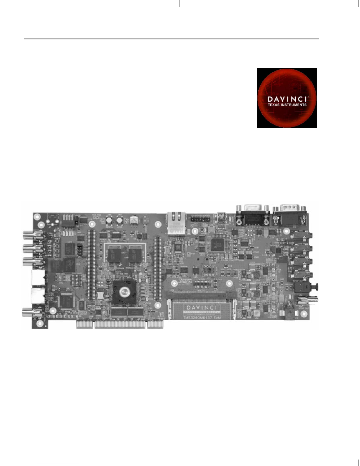
The DM6437 EVM board looks like this:
The intended audience is a developer of DSP software on the DM643x
DSP.
1-2
Diagram provided courtesy of Spectrum Digital Inc.
Page 11

1.2 What’s in this Kit?
Your DVDP kit contains the following hardware items. Section 2.1,
Setting Up the Hardware tells how to connect these components.
DM6437 EVM Board. This board contains a DaVinci
USB cable. This connects the EVM board to your PC workstation to
Universal power supply. Use this to power the board.
Ethernet cable. This connects the EVM board to a PC workstation
The DVDP kit also comes with the following software CDs. Information
about how to use the software components is provided in Chapter 4.
Digital Video Software Development Kit (DVSDK) case (from
What’s in this Kit?
TMS320DM6437 DSP device.
enable emulation debugging via Code Composer Studio.
to enable the host side of the demo application.
Texas Instruments)
CD 1 of 2. Contains Microsoft Windows installer for Codec
Engine software and demos and an evaluation version of codecs
(H.264 encoder/decoder, MPEG4 decoder, and G.711
encoder/decoder). Also contains documentation, drivers, Chip
Support Library (CSL), Digital Video Test Bench, and an
evaluation version of Network Developer’s Kit (NDK).
CD 2 of 2. Contains sample AV files.
DM643x SoC Analyzer case
CD 1 of 1. Contains Windows installer for SoC Analyzer.
VirtualLogix™ VLX for Digital Media (22 CD-ROMs)
The VirtualLogix DVD case contains royalty-free VirtualLogix
Linux, VirtualLogix VLX Real-Time Virtualization™ software, and
the TI ’C6000 Linux compiler evaluation software. This software
set allows you to develop low-cost products that require the realtime response, codecs, and applications of TI's real-time
DSP/BIOS™ kernel, combined with the advanced protocol
stacks, device drivers, GUI, and rich features of the Linux™
operating system, all running on a DM643x or ’C642x DSP.
Spectrum Digital case
CD 1 of 1. Contains Spectrum Digital Board Support Package
(BSP), drivers and diagnostics, Sheldon Instruments PCI host
driver, and DM6437 EVM-specific installer for Code Composer
Studio. This CCStudio install package includes DSP/BIOS, the
Fast FlashBurn utility, the Chip Scale Package (CSP), and more.
TMS320DM6437 DVDP Overview 1-3
Page 12
What’s on the Board?
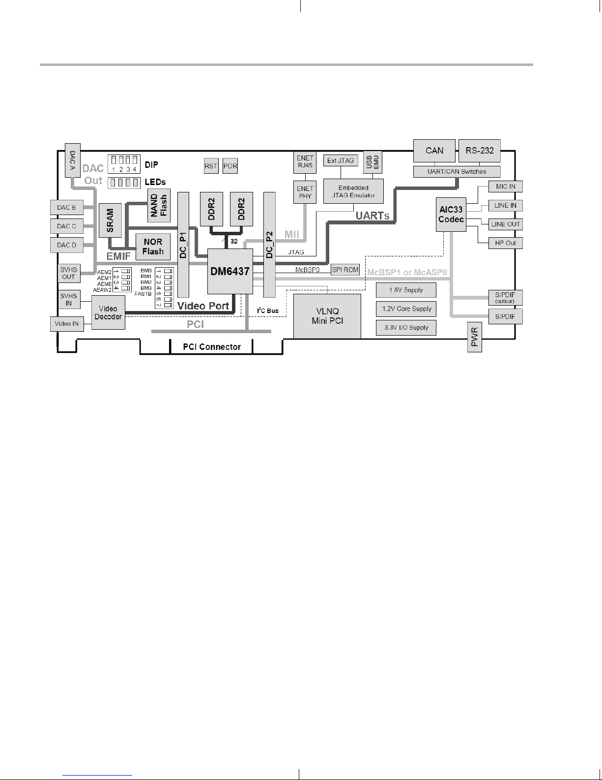
1.3 What’s on the Board?
The following block diagram shows the major hardware components on
the DM6437 EVM.
1.4 What’s Next?
Diagram provided courtesy of Spectrum Digital Inc.
Figure 1–1 DM6437 EVM Hardware Block Diagram
For more information about the DM6437 EVM hardware, see the website
at http://c6000.spectrumdigital.com/evmdm6437.
To get started evaluating the DVDP and developing applications for the
DM643x, begin by using this Getting Started guide. It will step you
through connecting the hardware, testing the software, and beginning to
develop applications.
When you are ready for more information about DaVinci Technology and
the DM643x architecture, see the following:
TMS320DM6437 Digital Video Development Platform (DVDP):
http://www.ti.com/dm6437dvdp
DM6437 EVM at Spectrum Digital:
http://c6000.spectrumdigital.com/evmdm6437
Codec Engine Application Developer's Guide (SPRUE67)
Other PDF documents on the CDs included with the DVDP
1-4
Page 13

Chapter 2
DVDP Hardware and Software Setup
This chapter tells you how to set up the DVDP hardware and software.
Topic Page
2.1 Setting Up the Hardware. . . . . . . . . . . . . . . . . . . . . . . . . . . . . . . . . . . 2–2
2.2 Installing the Software . . . . . . . . . . . . . . . . . . . . . . . . . . . . . . . . . . . . 2–6
2-1
Page 14
Setting Up the Hardware
2.1 Setting Up the Hardware
To set up the hardware, use the steps that follow:
1) The DVDP is sensitive to static discharges.
Use a grounding strap or other device to
prevent damaging the board.
Be sure to connect communication cables
before applying power to any equipment.
To be ESD safe, do not plug in the power cord
of peripheral devices such as audio and video
input and output devices until the later step
that instructs you to do so.
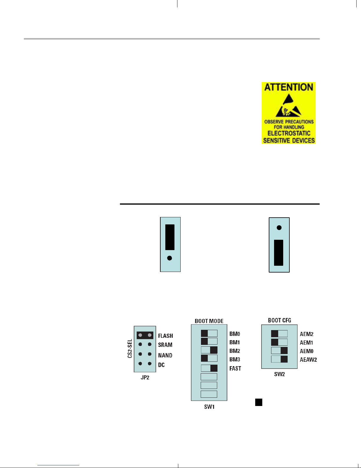
2) Verify that the board jumper JP1 is set to the correct display format—
either NTSC or PAL—as shown in the following diagram.
Board Edge
NTSC
JP1
OR
JP1
PAL
3) Verify that the board jumpers and switches are set as shown in the
following diagram so that the boot mode is EMIF boot (out of Flash).
Switches are "on" when switched to the right.
= switch location
2-2
Page 15
Setting Up the Hardware
4) Install the following software using the CDs included with the kit. See
Section 2.2, Installing the Software for more details.
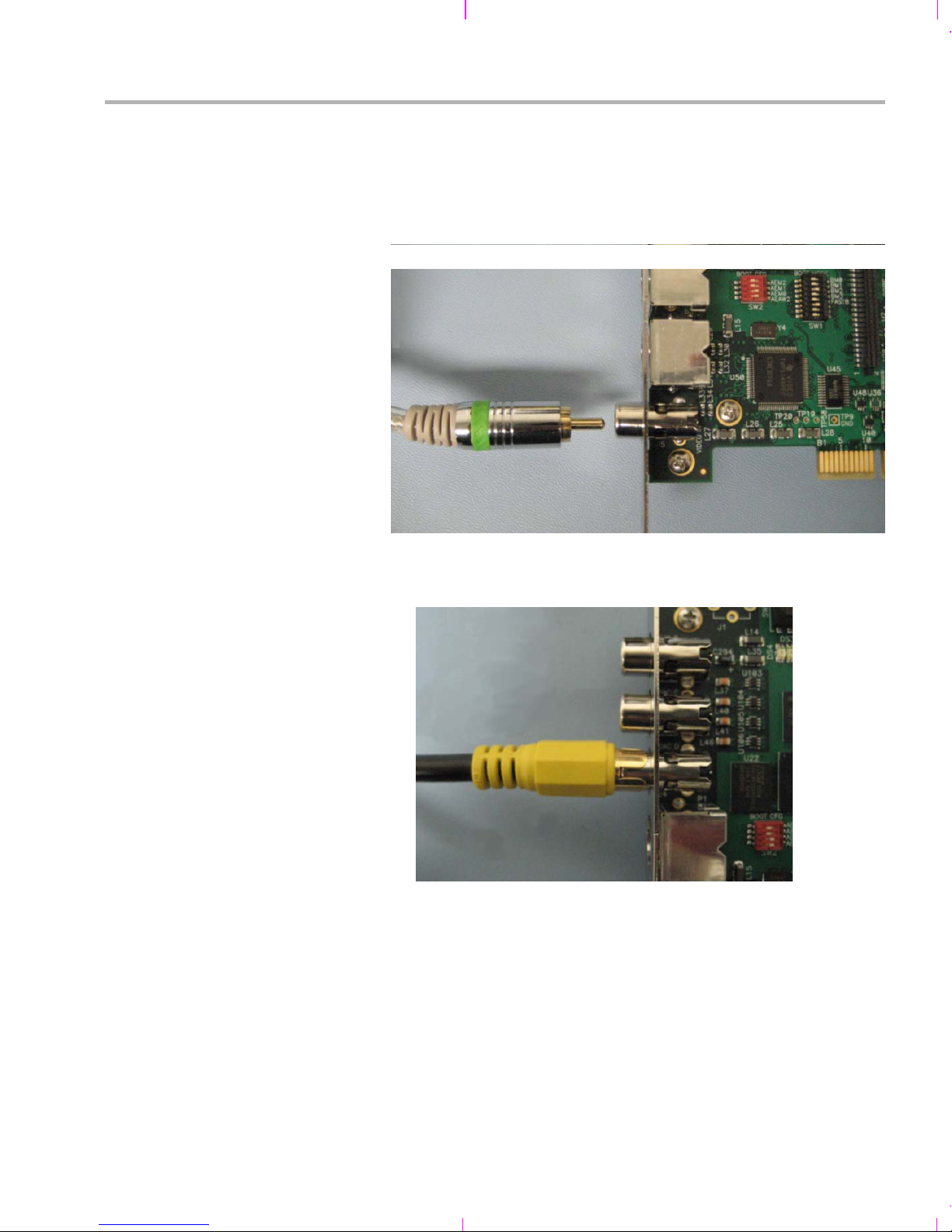
5) Connect a composite video cable from an NTSC or PAL video
camera or some other video input device to the EVM board’s Video
In RCA jack J5 as shown below.
6) Connect a composite video cable from a video display to the EVM
board’s DAC D Video Out RCA jack J4.
DVDP Hardware and Software Setup 2-3
Page 16
Setting Up the Hardware
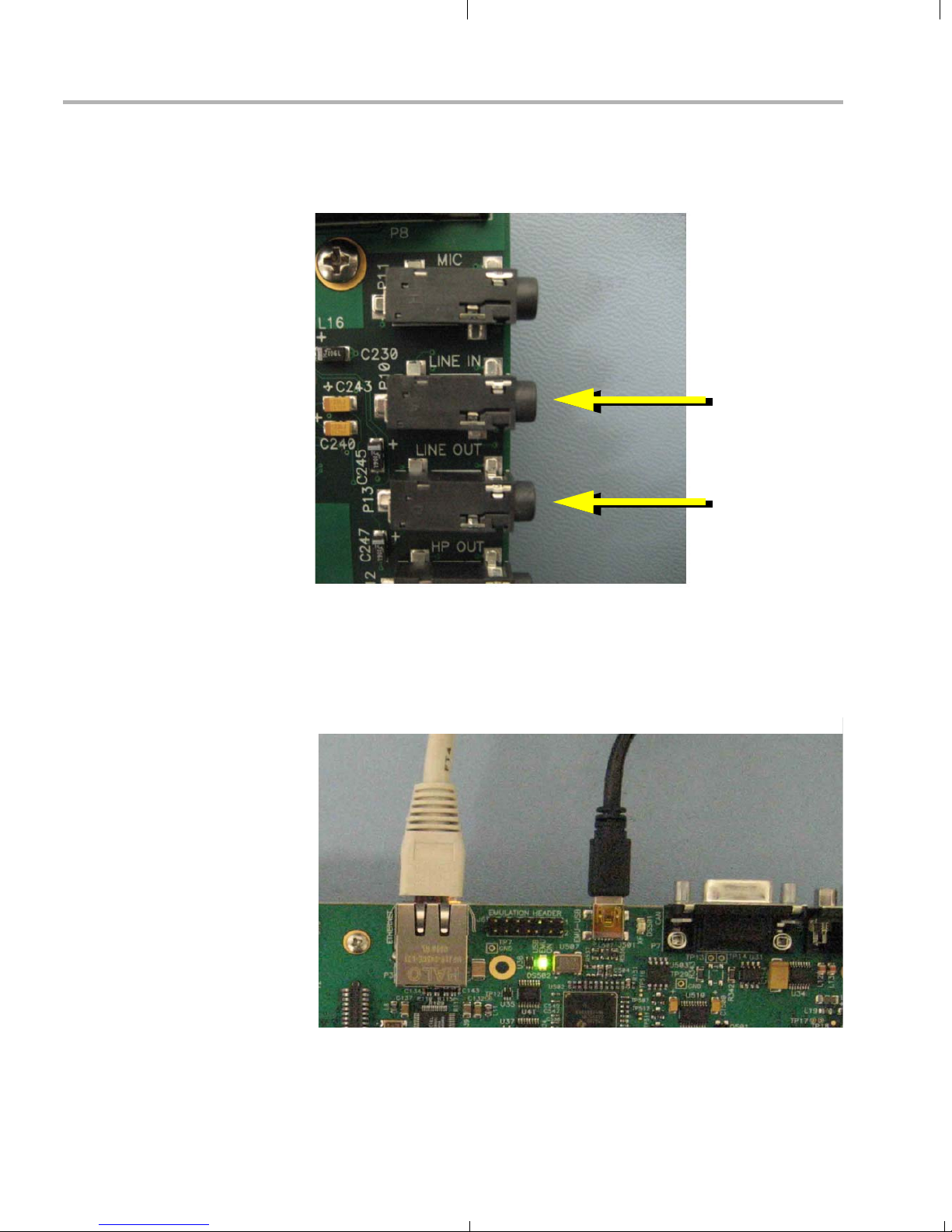
7) Connect an audio cable from a CD player, microphone, or other
audio device to the EVM board’s Audio Line In Connector 3.5 mm
stereo jack P10.
Audio Input
Audio Output
8) Connect an audio cable from a speaker to the EVM board’s Audio
Line Out Connector 3.5 mm stereo jack P13.
9) Use the provided USB cable to connect the EVM's USB connector to
a PC. You may want to connect through a USB hub for safety. The
USB connection enables debugging via Code Composer Studio.
Ethernet
Ethernet
10) Use the provided Ethernet cable to connect the EVM's Ethernet
connector to the same PC workstation to enable the host-side part of
the demo application.
USB
USB
2-4
Page 17
Setting Up the Hardware
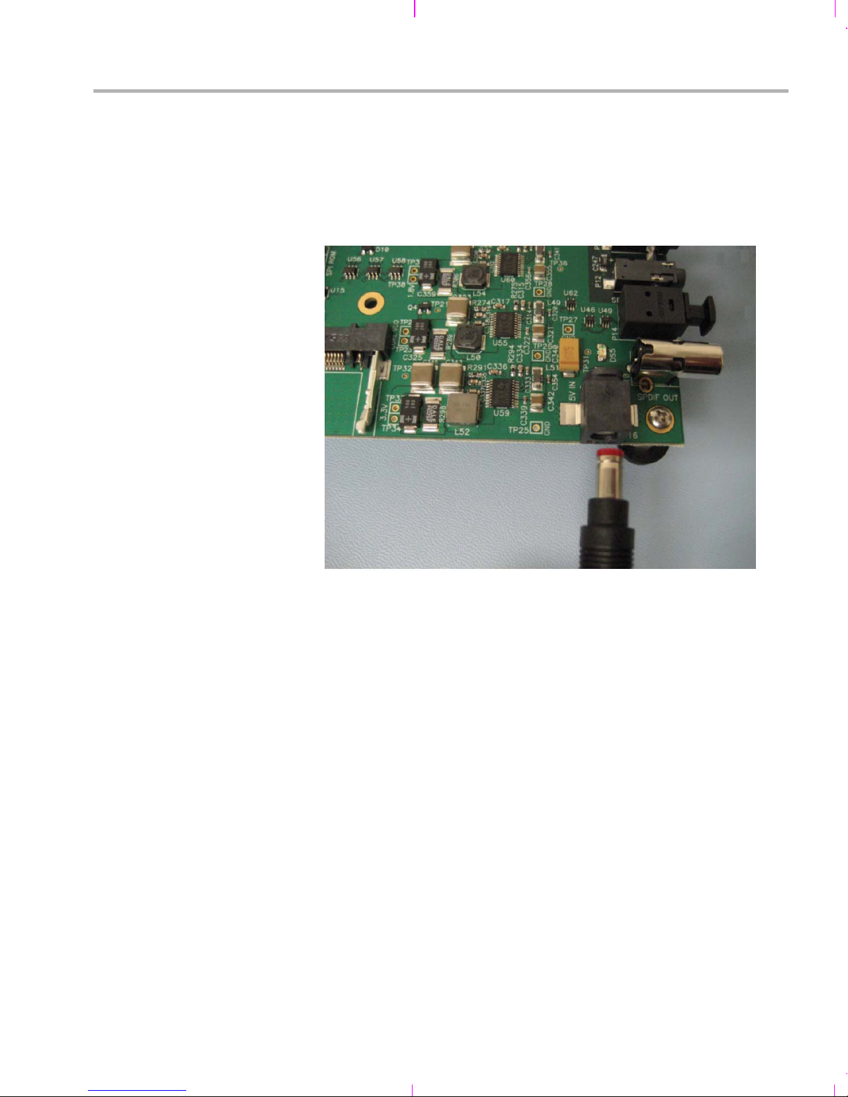
11) Plug in the video camera, video display, audio input device, and
speaker (if necessary).
12) Connect the provided +5V power supply to an AC power source.
13) Connect the provided +5V power supply to the EVM board’s power
connector as shown below.
14) You should see the following actions:
The EVM board should boot up and start executing the demo
application in standalone mode (from flash).
Live video from the video source should display on the video
output device. Live audio should be played if SW4-3 is set to the
down position.
You can switch the demo mode using the Video Mode Switch
(SW7). See Section 3.2, Running the Demos in Standalone
Mode.
15) If you have used the USB cable to connect the board to your PC, you
will see the Windows "Add New Hardware Wizard". If you are using
Windows XP, the USB driver files should be found automatically. If
the driver files are not found automatically, they are located on the
Spectrum Digital CD with the filenames targ645x.inf and
sdusb2em.sys. See the TMS320DM6437 EVM Quick Start
Installation Guide for USB debugging and troubleshooting hints.
DVDP Hardware and Software Setup 2-5
Page 18

Installing the Software
2.2 Installing the Software
To install the software needed to use the DVDP, follow these steps:
1) Use the Spectrum Digital CDs to install Code Composer Studio 3.3.
2) Also use the same Spectrum Digital CDs to install the DM6437 EVM
Drivers and Target Content.
3) Optionally use the SoC Analyzer CD to install the SoC Analyzer
software. See the SoC Analyzer documentation for details.
4) Install the DVSDK software for your board by following these steps:
a) Insert the Digital Video Software Development Kit (DVSDK) CD
#1 of 2 and allow the installer to autostart or alternatively run the
DM6437_DVSDK_setupwin32_1_xx_xx_xx.exe file, where "xx"
indicates the version and build numbers.
b) When you are prompted for an installation directory, we strongly
recommend that you use the default location. If the DVSDK is
installed in a nonstandard location, you will need to edit the
xdcpaths_evmDM6437.dat file located in the top-level directory
to modify the path set for dvsdkInstallDir so that it points to the
actual installation location.
c) The DVSDK installer automatically launches the DSP/BIOS
installer, dsp_bios_setupwin32_5_xx_xx_xx.exe, to update your
Code Composer Studio directory with a newer release of
DSP/BIOS (where "xx" indicates the version and build numbers).
You will also need to:
Make sure the BIOS_INSTALL_DIR environment variable is
changed to point to this new version of DSP/BIOS:
BIOS_INSTALL_DIR = C:/CCStudio_v3.3/bios_5_xx_xx
Launch the CCStudio Component Manager and modify the
Target Content (DSP/BIOS)->TMS32067xx setting to use
the updated version of DSP/BIOS.
d) A minimal set of A/V clips is installed automatically from CD #1.
If you want to install the full complement of A/V clips, insert
DVSDK CD #2 of 2 and run the dvsdk-avinstaller.exe installer.
5) See the release_notes_biosdvsdk_1_xx.html file installed with the
DVSDK for the latest information about the software in the DVSDK
and the index_manuals.html file for links to other documents in the
DVSDK.
2-6
Page 19

Installing the Software
The DVSDK installation creates the following key directories in the
default directory, which is C:\dvsdk_1_xx_xx_xx.
biosutils_1_xx_xx. DSP/BIOS Log Server for NDK programs.
codec_combos. Codec combinations that use the Codec Engine.
codec_engine_1_xx_xx. The Codec Engine framework.
codecs_1_xx. A/V codecs packaged for Codec Engine.
data. Audio and video sample data files.
dm6437_demo_1_xx_xx. Demonstration software.
docs. Various documentation.
dvtb_1_xx. Digital Video Test Bench.
examples. CCStudio project-based examples.
flashburn_files. Files for use with the FlashBurn utility.
framework_components_1_20. Components for use with xDAIS.
ndk_1_92_xx_xx_eval. Network Developer’s Kit evaluation.
PSP_1_xx_xx_xx. Product Support Package.
xdais_5_20. The xDAIS interface standard and xDM extensions.
xdc_2_xx_xx. Packaging and configuration tools.
6) Some components require extra configuration to be able to build and
run the examples. For details, you should see the release notes of
individual components. Some highlights are included here:
For the NDK examples, create the following Windows
environment variables. Substitute the appropriate version
numbers where these commands use "x":
NDK_INSTALL_DIR = C:\dvsdk_1_xx_xx\ndk_1_92_xx_xx_eval
BSL_EVMDM6437_INSTALLDIR = C:\CCStudio_v3.3\boards\evmdm6437_v2
For the Codec Engine examples, follow the instructions in
codec_engine_1_xx_xx\examples\build_instructions.html.
DVDP Hardware and Software Setup 2-7
Page 20

2-8
Page 21

Chapter 3
Running the Demonstration Software
This chapter explains how to run the software demos provided with the
DVDP.
Topic Page
3.1 Overview of the Demo Software. . . . . . . . . . . . . . . . . . . . . . . . . . . . . 3– 2
3.2 Running the Demos in Standalone Mode . . . . . . . . . . . . . . . . . . . . . 3–2
3.3 Running the Demos with the PC Host Application. . . . . . . . . . . . . . 3– 4
3.4 About Buttons and Switches . . . . . . . . . . . . . . . . . . . . . . . . . . . . . . 3 –12
3-1
Page 22
Overview of the Demo Software
3.1 Overview of the Demo Software
The demo software provided with the DVDP allows you to run examples
that encode and/or decode a signal. The examples can be run either
entirely on the target (standalone) or via a PC host application. Four
example modes are provided:
Preview mode. (Also called Capture / Display mode.)
Encode mode.
Decode mode.
Encode / Decode mode. (Also called Loopback mode.)
The algorithms used are H.264 or MPEG4 for video and G.711 for audio.
3.2 Running the Demos in Standalone Mode
When you power up the board, the pre-loaded demo application runs
automatically from Flash memory. You should see the following actions:
The EVM board boots up and starts executing the demo application
in standalone mode (from flash).
Live video from the input video device (for example, a camera)
displays on the video output device.
By default, the standalone demo runs in Preview (Capture/Display)
mode. In this mode, audio and video are captured by the input devices
and sent directly to the output devices. No encoding and decoding is
performed.
If the demo is running standalone, you can switch the demo mode using
the Video Mode Switch (SW7). The Encode/Decode Loopback mode
also captures audio and video from the input devices and send it to the
output devices. However, the signals are encoded and decoded using
are H.264 or MPEG4 for video and G.711 for audio.
Capture/Preview ModeEncode/Decode Mode
3-2
SW7
Page 23

Running the Demos in Standalone Mode
The Capture/Display mode uses D1 format for video display. D1 has a
resolution of 720 × 480 pixels if you are using NTSC and 720 × 576 pixels
if you are using PAL.
The Encode/Decode Loopback mode uses CIF format for video display.
CIF (Common Intermediate Format) video format, when using NTSC,
has a resolution of 352 x 240 pixels and a frame rate of about 30 frames
per second. If you are using PAL, CIF has a resolution of 352 x 288 pixels
and a frame rate of about 25 frames per second.
The demo also reads the SW4-3 switch (the rightmost switch when
looking at the board edge-on) at startup and enables audio output if the
switch is in the DOWN position.
3210
Edge-On View
SW4-3 Up = Audio Disabled (default)
SW4-3 Down = Audio Enabled
SW4
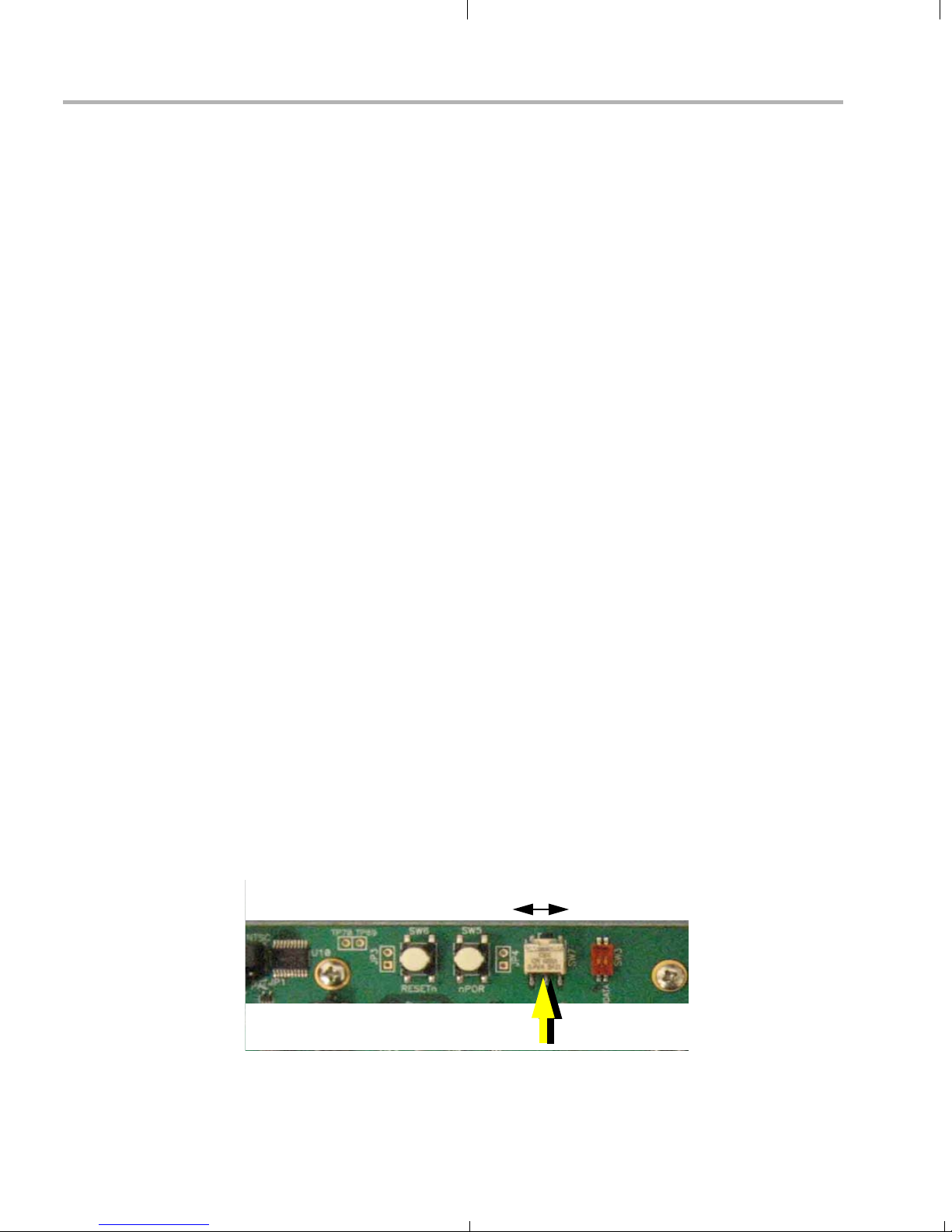
To restart the demo, you can press the Reset button (SW6), which resets
the DSP chip.
SW4
Reset
(SW6)
nPOR
(SW5)
SW7
Note: Avoid using SW5. In contrast to SW6, the nPOR (power-on
reset) button (SW5) resets everything on the board, including the
on-board emulator—resulting in a need to restart Code Composer
Studio if you were using it.
Running the Demonstration Software 3-3
Page 24

Running the Demos with the PC Host Application
3.3 Running the Demos with the PC Host Application
The target-side demo application is stored in Flash memory and runs
automatically when you power up the board.
Alternately, you can run the target-side demo application manually by
following these steps:
1) If you have not already done so, use CCStudio Setup to select the
DM643x platform.
2) Connect to the DM6437 by choosing Debug->Connect (Alt+C).
3) Reset the CPU by choosing Debug->Reset CPU (Ctrl+R).
4) Within CCStudio, choose File->Load Program and select the
dm643x_demo.out file in the Debug subdirectory. This loads the
target program onto the DM6437 EVM.
5) Use CCStudio to run the program on the target. If you like, you can
run the target program on more than one DM6437 EVM if they are
connected to your network.
The PC host-side application lets you control the target-side demo
application. The host-side and target-side applications exchange data
only through the IP network (not through JTAG).
3-4
Page 25

Running the Demos with the PC Host Application
To run the host-side component of the demo application, follow these
steps:
1) To start the host-side demo application, run the run.bat file in the
C:\dvsdk_1_xx_xx_xx\dm6437_demo_x_xx_xx\hostapp directory.
You can run this file from a DOS prompt or double-click on the file in
Windows Explorer. You will see a window that looks like this:
Running the Demonstration Software 3-5
Page 26

Running the Demos with the PC Host Application
2) Click the Discover button to find the IP address of the EVM board.
(If more than one board is found, the IP and MAC addresses of all
boards running the target application are listed in the drop-down, and
you can select the one you want. The MAC address is also shown on
the physical board.)
3) Click the Connect button.
The Status display should change to "Connected". The application is
probably already running in its automatic startup mode.
4) You can see dynamically-updated information about the application’s
status in the Target Application area. Tabs provide General Info
(application and component versions), Codec Stats (frame rates, bit
rates, and frame counts for encoders and decoders in use), and
System Stats (used and free memory and buffer information) are
provided. In addition, the CPU load on the target DSP and the
network data transfer rate (from the host’s perspective) are shown in
this area. The CPU load includes the load consumed by
communication between the host and target.
3-6
Page 27
Running the Demos with the PC Host Application
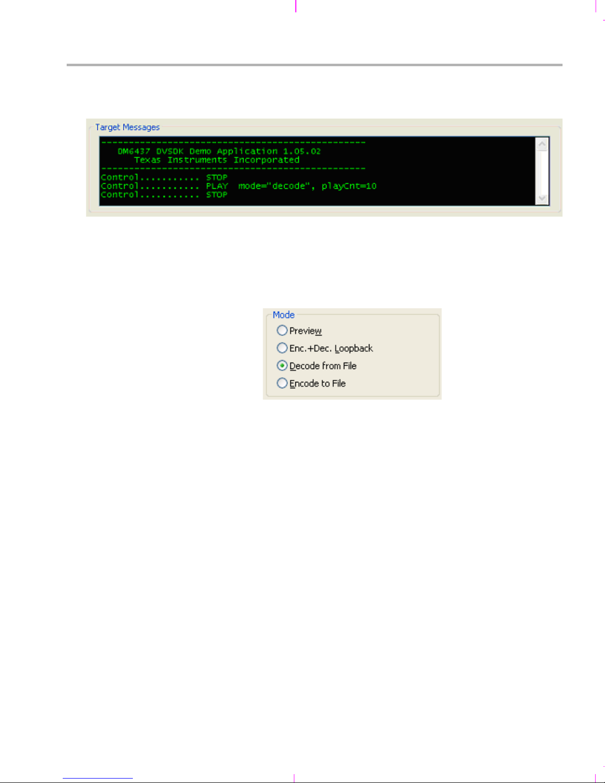
5) You can read log messages from the target-side application in the
Target Messages area:
6) To configure the application, you must first click Stop at the bottom
of the window. This makes the Control area active.
7) In the Mode area, select the mode in which you want to run the demo.
Then, go to the section indicated in this book for information on
choosing files for the mode you selected and running the demo.
Preview (also called Capture/Display mode).
See Section 3.3.1.
Enc.+ Dec. Loopback (also called Encode / Decode mode).
See Section 3.3.2.
Decode from File. See Step 9 and Section 3.3.3.
Encode to File. See Step 10 and Section 3.3.4.
Running the Demonstration Software 3-7
Page 28

Running the Demos with the PC Host Application
8) In the Video Settings area, choose the video codec and its properties
for the current demo mode. You can select H.264 or MPEG4
encoding and decoding. Optionally, you can set a custom frame rate
and/or encoding bit rate (either a variable or constant bit rate). For the
encoding resolution, you can select full image or quarter image for
NTSC and PAL.
When you select a file for decoding or encoding, the codec selection
changes automatically based on the file extension. Verify that the
selection is correct before running a decode or encode operation.
Note: It is possible to choose settings that result in sub-optimal
video quality or that overrun the available MHz of the processor.
There are no automatic checks against non-optimal parameter
settings, so you should carefully choose settings and examine the
resulting video output quality and DSP performance load against
the design requirements. For example, it is not recommended to
set the bit rate lower than 2 Mbps if you are using the H.264
encoder at D1 resolution.
The host application provides these controls for experimental
purposes. They allow you to experiment with the limits of
performance and quality. If you experiment with them, keep in mind
that some settings will necessarily degrade performance and quality.
3-8
Page 29
Running the Demos with the PC Host Application
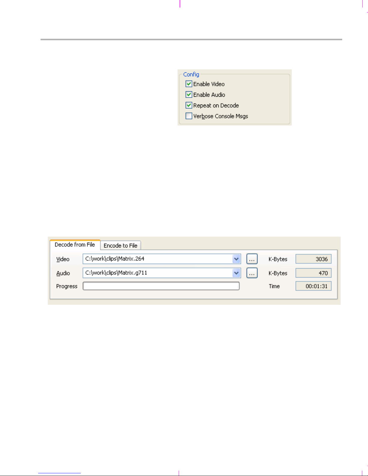
9) In the Config area, choose various options for how the application
should run:
Enable Video. On by default. Off disables video preview and
encode/decode.
Enable Audio. On by default. Off disables audio preview and
encode/decode.
Repeat on Decode. Tells the target to repeat the file when
decoding from a file. That is, to play it indefinitely.
Verbose Console Msgs. Tells the target to send more detailed
messages about its operation.
10) If you select "Decode from File" mode, you can select a file to decode
in the Decode from File tab.
To select a video input file, click the "..." button next to the Video field.
Browse to a H.264 or MPEG4 file and click Open. For sample data
files, browse to the C:\dvsdk_1_xx_xx_xx\data\video folder.
To select an audio file, click the "..." button next to the Audio field.
Browse to a G.711 file and click Open. For sample data files, browse
to the C:\dvsdk_1_xx_xx_xx\data\sounds folder.
Note that the input video and audio files need to be "raw" files. These
do not contain header information, just raw H.264, MPEG4, and
G.711 data. You can download the free VLC Media Player utility,
which can convert standard media files to "raw" files.
Running the Demonstration Software 3-9
Page 30

Running the Demos with the PC Host Application
After you click Play, the Progress bar shows the percentage of the
video file that has been consumed by the target's video decoder. The
K-Bytes fields show the number KB of video and audio processed
thus far. The Time field shows how long the application has been
running in Decode from File mode.
11) If you select "Encode to File" mode, you can select a file location to
store the encoded output from the target-side application.
To select a video output file, click the "..." button next to the Video
field. Browse to the location where you want the file stored. The
C:\dvsdk_1_xx_xx_xx\data\video folder is the default. Type a
filename and click Save. No file extension is added automatically.
You might want to use .h264 or .mpeg.
To select an audio output file, click the "..." button next to the Audio
field. Browse to the location where you want the file stored. The
C:\dvsdk_1_xx_xx_xx\data\sounds folder is the default. Type a
filename and click Save. No file extension is added automatically.
You might want to use .g711.
Note that the output video and audio files generated are "raw" files.
These do not contain header information, just raw H.264, MPEG4,
and G.711 data. You can download the free VLC Media Player utility,
which can convert "raw" file to standard media files.
You can set a time limit for encoding in the File Output area. This
prevents your disk from filling up if you leave the application running.
The default is one minute. Be aware that the files generated are quite
large, especially if you extend the time limit.
The K-Bytes fields show the number KB of video and audio
processed thus far. The Time field shows how long the application
has been running in Encode to File mode.
12) Click Play to begin the demo and Stop to halt the demo.
3-10
Page 31

3.3.1 Preview Mode (Capture / Display)
This mode does not use an input file or an output file. It simply captures
video from the input video device (for example, a camera) and sends it to
the display. If audio is enabled, it captures audio from the audio input (for
example, a microphone) and sends it to the speaker.
The signals are sent directly without any encoding and decoding.
3.3.2 Enc.+ Dec. Loopback Mode
This mode does not use an input file or an output file. It captures video
from the input video device (for example, a camera) and sends it to the
display. If audio is enabled, it captures audio from the audio input (for
example, a microphone) and sends it to the speaker.
The H.264 algorithm is used internally to encode and decode the video.
The G.711 algorithm is used internally to encode and decode the audio.
Running the Demos with the PC Host Application
3.3.3 Decode from File Mode
Decode from File mode requires a video input file. If audio is enabled, it
also requires an audio input file. It decodes the input files and sends the
output signals to the display (and to the speaker if audio is enabled).
The video input file must have been encoded using H.264 or MPEG4.
The audio input file must have been encoded using G.711.
3.3.4 Encode to File Mode
Encode to File mode requires a video output file. If audio is enabled, it
also requires an audio output file. It encodes video from the input video
device (for example, a camera) and audio from the audio input and sends
the encoded signals to the files you select.
The video input file will be encoded using H.264. The audio input file will
be encoded using G.711.
Running the Demonstration Software 3-11
Page 32

About Buttons and Switches
3.4 About Buttons and Switches
The subsections that follow describe some useful buttons and switches
on the board.
3.4.1 PAL/NTSC Switch
The board jumper JP1 determines whether NTSC or PAL is used. The
jumper controls this setting as shown in the following diagram.
JP1
Board Edge
NTSC
OR
JP1
PAL
3.4.2 Demo Mode Switches
By default, the standalone demo runs in Capture/Display mode. In this
mode, audio and video are captured by the input devices and sent
directly to the output devices. No encoding and decoding is performed.
You can switch the demo mode using the Video Mode Switch (SW7).
The Capture/Display mode uses D1 format for video display. D1 has a
resolution of 720 × 486 pixels if you are using NTSC and 720 × 576 pixels
if you are using PAL.
The Encode/Decode Loopback mode also captures audio and video from
the input devices and send it to the output devices. The signals are
encoded and decoded using H.264 for video and G.711 for audio. The
Encode/Decode Loopback mode uses CIF format for video display. CIF
(Common Intermediate Format) video format, when using NTSC, has a
Capture/Preview ModeEncode/Decode Mode
SW7
3-12
Page 33

About Buttons and Switches
resolution of 352 x 240 pixels and a frame rate of about 30 frames per
second. If you are using PAL, CIF has a resolution of 352 x 288 pixels and
a frame rate of about 25 frames per second.
The demo also reads the SW4-3 switch (the rightmost switch when
looking at the board edge-on) at startup and enables audio output if the
switch is in the DOWN position.
3210
Edge-On View
SW4-3 Up = Audio Disabled (default)
SW4-3 Down = Audio Enabled
SW4
3.4.3 Reset Buttons
Reset
SW4
To restart the demo, you can press the Reset button (SW6), which resets
the DSP chip.
Note: Avoid using SW5. In contrast to SW6, the nPOR (power-on
reset) button (SW5) resets everything on the board, including the
on-board emulator—resulting in a need to restart Code Composer
Studio if you were using it.
(SW6)
nPOR
(SW5)
SW7
Running the Demonstration Software 3-13
Page 34

3-14
Page 35

Chapter 4
Rebuilding DVDP Software
This chapter explains how to rebuild the software provided with the
DVDP.
Topic Page
4.1 Software Overview . . . . . . . . . . . . . . . . . . . . . . . . . . . . . . . . . . . . . . . 4 –2
4.2 Rebuilding the Demo Target Software. . . . . . . . . . . . . . . . . . . . . . . . 4–3
4-1
Page 36

Software Overview
4.1 Software Overview
The DaVinci software approach provides interoperable, optimized,
production-ready video and audio codecs that leverage DSP and
integrated accelerators. These codecs are built into configurable
frameworks, and are presented via published APIs within popular
operating systems (such as Linux) for rapid software implementation.
4.1.1 Software Components
The software included with the TMS320DM6437 DVDP is the Digital
Video Software Development Kit (DVSDK).
The heart of this software is the Codec Engine programming model.
Related components include the DSP/BIOS target operating system,
drivers, a networking stack (evaluation version). Customers can use the
provided Codec Engine or choose individual components for their own
video application development.
For the TMS320DM6437 DVDP, which is a DSP-only kit, the DVSDK
includes Microsoft Windows host software.
For more information about the software components used in these
applications see www.ti.com and the PDF files included with the
installation.
4-2
Page 37

4.2 Rebuilding the Demo Target Software
As a way to prepare to develop your own applications, you may modify
the target demo applications provided with the DVDP. This document
does not discuss in detail how to modify these applications.
4.2.1 Rebuilding the Examples
To rebuild the examples, follow these steps:
1) Make sure that xdcpaths.mak has the correct path for
DAVINCI64LC_INSTALL_DIR and BIOS_INSTALL_DIR. These
should normally be set to the following:
DAVINCI64LC_INSTALL_DIR := C:/dvsdk_1_xx_xx_xx
BIOS_INSTALL_DIR := c:/CCStudio_v3.3/bios_5_31_xx
2) If you want to build from within the CCStudio IDE, follow these
substeps:
Choose Project->Open and browse to the directory for the
example you want to rebuild. (For example,
C:\dvsdk_1_xx_xx_xx\examples\<example_name>.)
Rebuilding the Demo Target Software
Select the <example_name>.pjt file.
Then choose Project-> Rebuild All.
3) Alternately, to build from the command line, follow these substeps:
Change directory to the location of the example to rebuild (for
example, C:\dvsdk_1_xx_xx_xx\examples\<example_name>).
Type the following command. Note that you much use forward
slashes in the path to timake.
C:/<path_to_CCS>/cc/bin/timake.exe <example_name>.pjt Debug
4.2.2 Viewing SoC Analyzer Logs
The SoC Analyzer is a powerful analysis tool that provides visibility into a
running application for debugging and optimizing its performance.
You can view graphical representations of running tasks, SWIs, and
drivers to easily identify unexpected behavior. Peripheral, CPU, and
EMIF load analysis help you quickly isolate bottlenecks. Inclusive and
Rebuilding DVDP Software 4-3
Page 38

Rebuilding the Demo Target Software
exclusive execution-time analysis of codecs, drivers, and tasks shows
whether algorithms are performing up to specifications and the impact of
preemption on their performance.
Data for the SoC Analyzer is collected in real-time from framework
instrumentation and is transported over TCP/IP for analysis and
visualization. Using a TCPI/IP transport has the advantage of enabling
local or remote data collection.
The SoC Analyzer provides advanced user interface features to allow
easy correlation of system activities, isolation of unexpected behavior,
and measurement of performance. For details, please see the SoC
Analyzer online help, which is available from the Analyzer Help menu.
4-4
Page 39

Rebuilding the Demo Target Software
The dm6437_demo.out file was built with device driver instrumentation
turned off. However, pre-built instrumented versions of the driver libraries
have been provided with the DVSDK product. To use these instrumented
drivers, simply follow these steps:
1) Right-click on the demo project in CCStudio, and select the
Instrumented option.
2) Rebuild the demo application.
3) Use CCStudio to load and run the
dm6437_demo_x_xx_xx\Debug\dm6437_demo.out file.
4) Launch the SoC Analyzer by selecting Start->All Programs->Texas
Instruments->SoC Analyzer 1.0->SoC Analyzer.
5) In the SoC Analyzer Control Panel, enter the IP address that was
displayed in the CCStudio stdout window.
6) In the SoC Analyzer Control Panel, enter the path to the .out file.
7) You can then user the SoC Analyzer to start capturing log data and
analyzing the results. See the SoC Analyzer's online help for more
information.
Rebuilding DVDP Software 4-5
Page 40

4-6
Page 41

Appendix A
Additional Procedures
This appendix describes optional procedures you may use depending on
your setup and specific needs.
Topic Page
A.1 Using the Bootloader . . . . . . . . . . . . . . . . . . . . . . . . . . . . . . . . . . . . . A–2
A.2 Replacing the Demo Codec Combinations. . . . . . . . . . . . . . . . . . . . A– 2
A.3 Using the FlashBurn Utility . . . . . . . . . . . . . . . . . . . . . . . . . . . . . . . . A– 3
A.4 Rebuilding the Demo Host Software . . . . . . . . . . . . . . . . . . . . . . . . . A–6
A-1
Page 42

Using the Bootloader
A.1 Using the Bootloader
You can select one of the following boot modes using the boot device
pins. When the board is reset, it captures the status of these pins and
branches to the appropriate code to implement the selected boot method.
No Boot (non-secure)
ROM Boot (non-secure)
HPI
PCI (DSP as slave)
AEMIF/NOR FLASH
AEMIF/NOR FLASH
I2C (DSP as master)
SPI (DSP as master)
UART (DSP as slave)
For information about which pins to use and details about the various
boot modes, see the Using the TMS320DM643x Bootloader (SPRAAG0)
application note.
A.2 Replacing the Demo Codec Combinations
The codecs used by the demo application are packaged as combinations
in C:\dvsdk_1_xx_xx_xx\codec_combos_1_00\ti\sdo\apps.
For information about combining other codecs to create your own Codec
Engine configuration, see Codec Engine Application Developer User's
Guide (SPRUE67). In particular, see Chapter 5 of that book.
A-2
Page 43

A.3 Using the FlashBurn Utility
If you want to place an update to the demo software or your own
application in Flash memory, you can use the FlashBurn plug-in utility.
Note: For the latest version of the FlashBurn utility and more information
about it, see the www.softwaredesignsolutions.com website.
Before you can use the FlashBurn utility, you must follow these
installation steps:
1) Install CCStudio 3.3.38.2 from the Spectrum Digital CD included in
the DVDP.
2) Install the EVM Target and Drivers Content from the Spectrum Digital
CD included in the DVDP.
3) Do NOT install the FlashBurn utility from the Spectrum Digital CD. Go
to http://www.softwaredesignsolutions.com/flashburn.aspx and
download the free FlashBurn DSK utility (registration required).
Install the FlashBurn DSK.
Using the FlashBurn Utility
4) Install the DVDP's DVSDK software, provided by TI. Within the main
install directory, there is a directory called "flashburn_files", which
contains all the needed files referenced in these instructions.
To flash the DM6437 EVM for booting in NOR FastBoot AIS mode, follow
these steps:
1) Connect the EVM to the PC via the supplied USB cable to use the
board’s embedded emulation support. Then, plug in the EVM.
2) Start DM6437 EVM CCStudio v3.3. Use the desktop
icon to start CCStudio, since this sets up the proper
board connection and loads the correct GEL file.
3) Make sure that the JP2 jumper is set to "Flash." If it is
not, shut down CCStudio, power off the board, and start
over at step 1 of these instructions.
4) Connect to the target EVM by pressing Alt+C in CCStudio.
5) Reset the CPU in CCStudio. (If you skip this step, FlashBurn has
trouble connecting to the EVM and loading its program successfully.)
6) Start the FlashBurn DSK Utility using the Windows Start menu to
choose All Programs->Software Design Solution->FlashBurn
DSK.
7) If you are ask to create a configuration, choose "Create a New
FlashBurn configuration". Otherwise, within the FlashBurn Utility,
choose File->New to start a new configuration file (.cdd).
Additional Procedures A-3
Page 44
Using the FlashBurn Utility
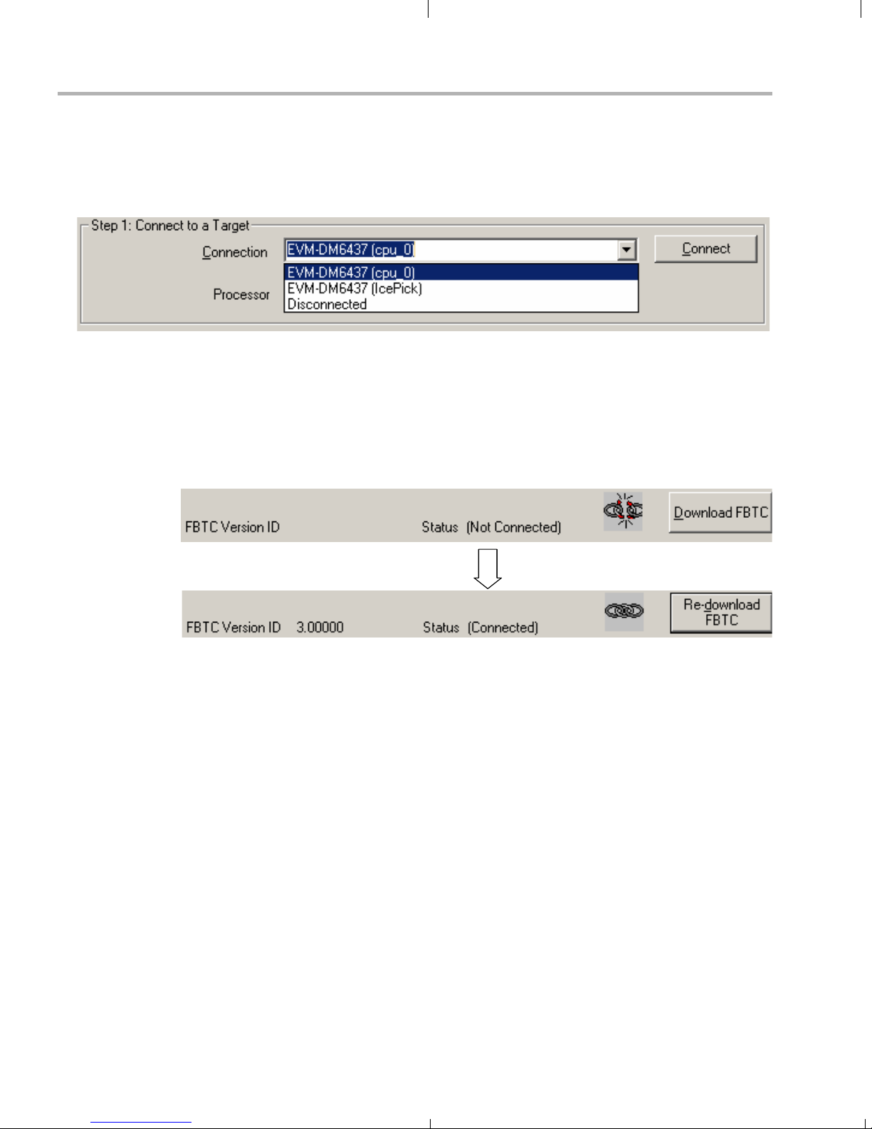
8) In the Step 1 area of the FlashBurn DSK dialog box, connect to the
target by choosing the "EVM-DM6437 (cpu_0)" Connection option
and clicking the Connect button. The dialog box shows the resulting
connection status.
9) In the Step 2 area, click the Browse (...) button next to the "FBTC
Program File" field. Locate and select the provided FlashBurn Target
Component (FBTC) file, FBTCEVMDM6437.out, which is located in
the flashburn_files directory of the DVSDK installation.
10) Click the "Download FBTC" button. The dialog box shows the
resulting connection status.
A-4
11) You may optionally click Erase Flash (in the Step 3 area of the dialog)
to perform a global erase of the NOR flash to prepare for writing.
12) Prepare the application to be flashed to the EVM. The file should be
in hexadecimal format (Motorola S-record or ASCII hex). You can
convert a CCStudio COFF file (a .out file) to a proper hex format
using the provided hexAIS tool, which is located in the
<DM6437_install_dir>\flashburn_files\hexAIS directory. For example
hexAIS a.out" command produces the file a.hex, which can be
the "
flashed to the NOR flash of the DM643x. This procedure uses the
included file, DM643x.ini, to provide information on basic initialization
of the system PLLs, DDR interface, and EMIFA interface. (The
hexAIS tool is a .NET application and requires that the Microsoft
.NET Framework v2.0 or higher to be installed. See the readme.txt
file for more details.)
13) In the Step 3 area, browse for the File to burn to the NOR flash. The
file should be in hexadecimal format as described previously. Leave
all other settings at their defaults.
Page 45

Using the FlashBurn Utility
14) Click the Burn icon or choose Program->Program Flash.
The status bar next to the Burn icon shows the progress of the
operation. The status bar of the window shows the result of the
operation when it is complete.
15) If the burn fails, do a complete erase of the NOR region, and then try
again.
16) When you are finished, close FlashBurn, press Alt+C to disconnect
CCStudio from the board, and power off the board. (You may save
the FlashBurn configuration file if you wish.)
17) Set the SW1 and SW2 switches as follows:
= switch location
18) Turn the board on. Your application should start. Note that the AIS
image format can only initialize the DDR memory (and the associated
PLL2), the system PLL (PLL1), the AEMIF interface, and the
PINMUX registers. Other required initialization steps (such as turning
on power domains) must take place in the user application.
Additional Procedures A-5
Page 46

Rebuilding the Demo Host Software
A.4 Rebuilding the Demo Host Software
If you want to modify the host-side demo application, you likely only need
to add or remove some buttons and drop-down lists and read and write
different target state parameters used by your target application. This can
be done by changing the GUI script in Main.js.
The demo host-side application runs on a host machine (typically a PC
running Windows or Linux) and connects over the network to a
TMS320DM6437 EVM board that is running the target-side demo
application. The host-side application lets users control the target’s
behavior and stream audio and video files to and from the target.
The host-side program is written in ECMAScript—popularly known as
JavaScript—and requires no development tools other than a text editor.
You run the program by running the .bat file located in the same directory
as the host-side application. (To run the program in a graphical debugger,
edit the .bat file itself and comment out the appropriate line.)
A.4.1 JavaScript Misconceptions
There are some common misconceptions about JavaScript. The core
JavaScript language, which is used for this program, has nothing to do
with Web pages; it is a general-purpose scripting language like Perl or
Python.
Also, JavaScript is not Java. However, it does let developers use existing
Java libraries without requiring the developer to be a Java programmer.
Three such libraries are used by the host-side application script:
Networking library
File I/O library
GUI library
These Java libraries are part of the XDC toolset, which is used primarily
for development of target software, and are included in the DM6437EVM
tools installation.
(Perl, an alternative scripting language, while more widely used, is
considered less coder-friendly and would require a separate installation
of Perl tools. Another alternative, executables developed with Microsoft
Visual C++, is less suitable for rapid development of applications like this
one and would require the installation of licensed Microsoft tools.)
A-6
Page 47

JavaScript's syntax allows C programmers to understand and (to a
degree) modify programs written in this language even if they have never
seen this language before. To learn how to make nontrivial modifications
or to write new JavaScript programs, please refer to this Web page:
http://developer.mozilla.org/en/docs/Core_JavaScript_1.5_Guide
Most C programmers will not need to refer to the JavaScript guide in
order to understand the scripts in this section. C programmers typically
"get" patterns of JavaScript scripts quickly and can replicate them without
formally learning the language.
Note that the host-side JavaScript scripts use Java library classes.
Modifying these statements requires knowing the APIs of the libraries in
question. However, using Java classes from JavaScript is much easier
than writing Java programs in Java.
A.4.2 Structure of the Host-Side Application
The host-side application is split into four modules:
Rebuilding the Demo Host Software
Main.js
(GUI control)
GUI control:
Main.js
Target control (RPC): Dm6437evm/Rpc.js
File I/O: Dm6437evm/Fileio.js
Networking (communicates with target): Dm6437evm/Ipc.js
Dm6437evm/Rpc.js
(target control)
Dm6437evm/Fileio.js
(file I/O)
Dm6437evm/Ipc.js
(networked communicaton
with target)
The main script, Main.js, is in charge of the GUI only. It draws buttons and
input fields and listens for user actions to send an appropriate command
to the target (for example, start playing, stop playing, and switch mode).
It also starts a separate thread to run fileio functions and thus serve the
target with input and output audio/video files.
Additional Procedures A-7
Page 48

Rebuilding the Demo Host Software
The Rpc.js script (Remote Procedure Call) provides the GUI script with
several functions, of which the important ones are:
rpc.connect( ipAddr ): Connects to the target at ipAddr.
rpc.paramGet( paramName ): Gets the state of a target parameter,
rpc.paramSet( paramName ): Changes the state of a target
rpc.controlPlay/Stop(): Starts and stops the target's audio/video
The paramGet() and paramSet() functions read and write state variables
on the target—such as I/O registers. These state variables are defined by
the target application. The demo application accesses several such
variables. For example:
"runFlag" indicates whether the demo running or stopped.
"audioEnableFlag" indicates whether audio is enabled.
such as "mode".
parameter. For example, sets "mode" to "decode".
processing.
"mode" indicates the current running mode.
The Fileio.js script has an even simpler API:
fileio.connect( ipAddr, port ): Connects to the target's fileio port.
fileio.recvCmd(): Receives File I/O commands from the target.
fileio.dispatchCmd(): Runs received File server commands, such
as "read".
The target sends commands like "open file xyz" or "read N bytes from the
file" to the host. The GUI script does not care what the commands are; its
only duty is to run the commands from a separate thread.
The Ipc.js script (Inter-Process Communication) takes data structures
from Rpc and Fileio, serializes them, and sends or receives them to or
from the target over the network. The API, which is not directly used by
the GUI script, provides the following functions:
ipc.connect( ipAddr, port ): Connects to the port at the given
address.
ipc.writeWord( word ): Writes a 32-bit word to the target.
ipc.readWord(): Reads a 32-bit word from the target.
ipc.writeString( string ): Passes a text string to the target.
ipc.readString(): Reads a text string from the target.
A-8
Page 49

For details about how the Rpc, Fileio, and Ipc modules work, see their
scripts directly. They follow certain rules for exchanging information
between the host and the target. It is unlikely you will have to change any
of those modules. If you want to modify the host and the target demo
application for your own needs, on the host side you most likely need to
change only the GUI script by adding or removing some buttons and
drop-down lists and reading and writing target state parameters used by
your target application.
A.4.3 The Main Application Script, Main.js
The flow of the main script is as follows:
Initialize target communication modules.
Draw buttons and other widgets on the screen.
Assign a function to each button.
Loop, waiting for the user to close the window.
Whenever the user clicks a button, the function assigned to the
button runs. Typically this sends some message to the target,
such as "connect" or "start playback".
Rebuilding the Demo Host Software
In more detail (and you may also want to refer to the code), Main.js flows
like this:
1) First Main.js loads the two scripts, Rpc.js and Fileio.js, that
implement communication with the target by sending messages to it
over the network. They let us create target communication objects
later on in main().
2) Then, Main.js defines global variables used in the Main.js script.
Some of these variables are references to library objects, others we
define as null and initialize later on.
We create aliases for the GUI Java libraries ("classes") used. We
do not use the standard Java GUI library but something called
"SWT" (Standard Windowing Toolkit), which is made by IBM for
its development environment, Eclipse. SWT works faster than
the standard Java GUI and looks like a "normal" Windows
application.
The "debugFxn" variable turns debugging on or off. This variable
is really a function (in JavaScript a variable can be of any type,
including a function). If a later script line executes the command
debugFxn( "Debug: File I/O thread started" );", the
"
result depends on "debugFxn" is defined. If "var debugFxn =
Additional Procedures A-9
Page 50

Rebuilding the Demo Host Software
3) The final outside-any-function statement executed by the Main.js
print;" and print() is a built-in function, the message appears. If
"var debugFxn = function() {}", all calls to debugFxn() are silent.
The global variables "rpc" and "fileio" are for target
communication. The global variables "display" and "shell" refer to
the system screen and the application's window. These are set
to null and will be initialized in main().
The variable "myWidgets" is a hash-table—an array whose
elements are accessed by name instead of by index—that is
initially empty. It is later filled with references to various screen
controls. For example, we will read what the user types in the
"txtIP1" box—the box with the first part of the target IP address—
by calling "myWidgets["txtIP1"].getText();". Or, we can find out
whether the user selected the "Encode" video mode with "if
(myWidgets["radioEncode"].getSelection() == true)".
script is main(), which calls the function main() defined below. In
JavaScript, a variable or function is in scope if it is defined anywhere
in the scope; it does not have to be defined before it is referenced.
The main() function first creates an Rpc object from the Rpc.js
module. After the "rpc" variable is initialized, any function in the
script can connect or send a message to the target, like
"rpc.connect( "168.123.012.99" )" or "rpc.controlPlay()".
The main() function creates a similar "fileio" variable for a fileio
object from the Fileio.js module. For details about the Rpc and
Fileio APIs, refer to their scripts.
The main() function next creates a "display" and a "shell",
initializing these global variables. The "display" is the whole
screen; the "shell" is where buttons and other widgets are drawn.
The main() function then calls the layoutWidgets() function to
draws the widgets.
The main() function then calls the setEventListeners() function to
assign "event listener" functions to be called when a button is
pressed.
The main() function calls a function to gray out everything except
the "connect" button's area, because the application has just
started and is not yet connected.
The main() function then runs a standard loop for SWT GUI
programs that refreshes the screen and calls event functions
when a button click (or some other widget event) occurs, leaving
the loop only when the user closes the main window.
A-10
Page 51

Rebuilding the Demo Host Software
Here is a diagram of the functions in Main.js and their actions:
Global
- load target comm. scripts
- define global variables
- call main()
main()
- create target comm. objects create GUI objects
- call layoutWidgets()
- call setEventListeners()
- loop till the user closes application
layoutWidgets()
- place all controls (buttons, text
boxes, control groups) on screen
setEventListeners()
- specify functions to be called
for each button and control
eventFxnBtnConnect()
- connect to the target
- read target state variables
- set widget state based on target state
- start the FileIo thread
eventFxnBtnDisconnect()
- disconnect from the target
etc. . .
Additional Procedures A-11
Page 52

Rebuilding the Demo Host Software
A.4.4 Drawing Screen Controls (Widgets)
Since we don’t use a graphical editor to draw the host-side application
widgets, we lay them out within the script in a recipe-like fashion. For our
application window (the "shell"), the script says which groups of widgets
are drawn next to, below, or within others.
A "widget" is a common name for a single element like a button, text field,
label, drop-down box, or a container for other widgets.
Containers are special because they can contain other widgets—both
simple elements and other containers. This application uses two kinds of
containers: "Groups" and "Composites". The difference between these is
that Groups have visible frames around the widgets they contain, while
Composites have no visible frames.
Another thing to know about containers is that a "grid" layout specify how
widgets inside them are laid out. Grids are matrices (including matrices
with only one row or column) in which each grid cell contains a widget
(including container widgets).
Each grid cell can be aligned left, right, or centered. A cell’s width or
height can also be controlled, but we usually don't have to. If we set the
width of a widget in pixels, the grid's column width adapts automatically
to match the widest element in the column. Also, if the widget size isn’t
specified, it adapts to the size needed to display its text.
A number of other properties of containers (for example, "margin width",
"vertical spacing", and "make all columns equal width") are available to
create professional-looking applications.
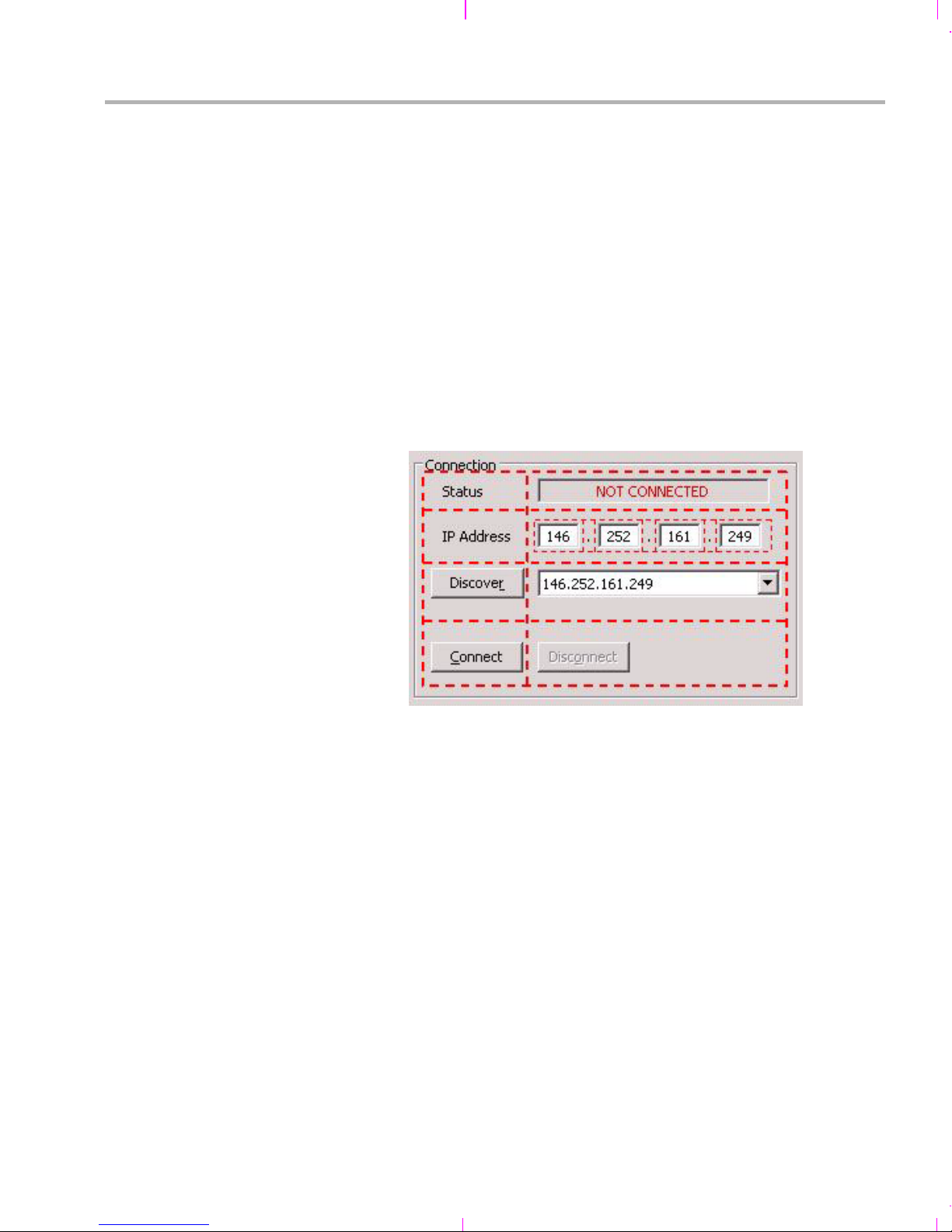
Here is an example. If you run the host-side application, the "Connection"
frame contains several buttons and text fields, one drop-down list (called
a "combo box"), and a few labels:
A-12
Page 53
Rebuilding the Demo Host Software
The "Connection" frame is a cell in a larger grid, but it could be the only
thing on the screen—we'd script it the same way. This needs to be a
"Group" container, because we want a visible frame with "Connection" as
the text. We give this container a grid with 2 columns in each row.
One challenge is that we have two widgets per row in all rows except the
second—the IP address takes 7 widgets: four text fields and three labels
(each containing just "." as its text). So, we treat the IP address set of
fields differently. We lump all of its widgets into an invisible "Composite"
container and put that composite in the second cell of the second row.
Then, as far as the "Connection" group is concerned, it sees only two
elements in each row.
The following figure shows how the widgets in the Connection frame are
grouped into containers and cells.
Let's look at the script code that does this layout. We define two handy
functions, WID() and END() (almost like macros) that make the code look
more readable. WID(<new widget>) adds the new widget to the current
widget, referenced with variable $w, and makes the new widget current
until a matching END() is called. WID() also returns the reference to the
newly created widget object, so that we can store it in the myWidgets[]
hash table. We only need to keep references to the widgets we may later
want to somehow control.
Additional Procedures A-13
Page 54

Rebuilding the Demo Host Software
The following code creates the "Connection" frame inside the current
widget, and adds the first two elements—the text and field in the first row.
Some formatting statements have been omitted to simplify this example.
WID( widgets.Group( $w, SWT.NONE ) );
$w.setText( "Connection" ); // $w = current widget
var gl = layout.GridLayout( 2, false );
$w.setLayout( gl );
WID( widgets.Label( $w, SWT.NONE ) );
$w.setText( " Status" );
END();
w["txtStatus"] = WID( widgets.Text( $w, SWT.BORDER | SWT.CENTER |
SWT.READ_ONLY ) );
$w.setLayoutData( GD( 164, SWT.DEFAULT ) );
END();
This code creates the "Connection" group, sets its label text
appropriately, and gives it a grid layout of 2 columns per row. The function
that creates a new layout is GridLayout( <#columns>, <make cols equal
width> ).
All widgets, when created, as a first argument take the reference of the
containing widget. With our macro-like functions, it is always "$w". The
second argument to a widget usually defines some attribute(s), such as
whether it has a border or how is its text justified.
We then add a label, "Status", and create a text box to contain the
connection status. The connection status text could be placed in another
label like "Status", because we can change the text of any widget
dynamically, but we use a text box for an aesthetic effect. We make the
textbox have a border, have its text center-aligned, and be read only; we
also record its reference in myWidgets["txtStatus"], where "w" is a short
alias for "myWidgets". In the next line, we say that the grid cell where the
text box is should be 164 pixels wide and have the default height
(determined by the textbox's font and font size).
To learn which widgets are available and which properties they have, see
the following web page. This site has a picture of each widget, its API
syntax, and an example code snippet.
http://www.eclipse.org/swt/widgets
A-14
Page 55

Rebuilding the Demo Host Software
The rest of the layout code for the "Connection" frame lays out the "IP
address" label, the invisible 7-column "Composite" with its IP address
fields and labels, the "Discover" button and combo box, and the
"Connect" and "Disconnect" buttons. Note how the END() function closes
the definition of a widget:
WID( widgets.Composite( $w, SWT.NONE ) );
var gl = new layout.GridLayout( 7, false );
gl.marginWidth = 0;
$w.setLayout( gl );
w["txtIP1"] = WID( widgets.Text($w,SWT.BORDER|SWT.CENTER ));
$w.setLayoutData( GD( 20, SWT.DEFAULT ) );
END();
WID( widgets.Label( $w, SWT.NONE ) );
$w.setText( "." );
END();
w["txtIP2"] = WID( widgets.Text($w,SWT.BORDER|SWT.CENTER));
$w.setLayoutData( GD( 20, SWT.DEFAULT ) );
END();
WID( widgets.Label( $w, SWT.NONE ) );
$w.setText( "." );
END();
... etc, for IP3 and IP4
END();
w["btnDiscover"] = WID( widgets.Button( $w, SWT.PUSH ) );
$w.setText( " Discove&r " );
END();
w["cmbDiscover"] = WID( widgets.Combo( $w, SWT.READ_ONLY ) );
$w.setLayoutData( GD( 158, SWT.DEFAULT ) );
END();
w["btnConnect"] = WID( widgets.Button( $w, SWT.PUSH ) );
$w.setText( " &Connect " );
END();
w["btnDisconnect"] = WID( widgets.Button( $w, SWT.PUSH ) );
$w.setText( " Disc&onnect " );
END();
END();
The indentation before WID() and END() functions lets us better see
which object contains which. It is not necessary to use WID() and END(),
but we use them because they improve readability of the code. (If you
place a widget in the wrong container, you'll often get drastically different
results.)
Additional Procedures A-15
Page 56

Rebuilding the Demo Host Software
A.4.5 Reacting to Button Clicks
The setEventListeners() function assigns a function to every widget the
user can click. The first such assignment—remembering that "w" is an
alias for the "myWidgets" hash table—is as follows:
w["btnDiscover"].addListener( SWT.Selection, eventFxnBtnDiscover );
That means, when the user clicks the "Discover" button, our
eventFxnBtnDiscover() function is to be called. If you look at the body of
that function further below, you'll see the expected—it calls the
rpc.discover() function, which returns zero or more IP addresses of
targets running the demo (determined by their response to a specific
broadcast message, see Rpc.js for details), and then fills in the
w["cmbDiscover"] drop-down list with those addresses and copies the
first in the list into the "IP address" input fields.
However, setEventListeners() defines shorter functions for events with
simpler actions right on the spot. Take this one for example:
w["btnInVideoBrowse"].addListener( SWT.Selection, function( event ) {
var dialog = new widgets.FileDialog( shell );
var fileName = dialog.open();
if (fileName != null) {
w["cmbInVideo"].add( fileName, 0 );
w["cmbInVideo"].select( 0 );
w["txtInVideoSizeKB"].setText( Math.floor( new java.io.File(
fileName ).length() / 1024 ) );
}
} );
A.4.6 Exceptions
A-16
This is a function for the "Browse for Input Video file" button. It opens a
new file dialog, and, if the user has selected a file, it adds the file to the
top of the "input video file" drop-down list and makes it the first choice.
Then, it reads the file's size and shows it in the "txtInVideoSizeKB" readonly textbox. (The function call java.io.File(fileName).length() returns the
file size in bytes or 0 if the file doesn't exist.) Such versatile Java library
functions make the scripts short.
(C++ and OOP developers can skip this section, since they will be
familiar with the type of exception handling used by JavaScript.)
The APIs provided by the Rpc.js, Fileio.js, and Ipc.js scripts have
functions that do not return success or failure. Instead, if en error occurs,
an "exception" is thrown, either by a system module that the function
Page 57

A.4.7 Threading
Rebuilding the Demo Host Software
uses or by the function itself if it detects some irregularity. That exception
travels up the call stack until it is caught. If no function catches it, the
application exits in an error with its call stack listed.
This behavior frees us from having to check the return status frequently.
Instead, we catch exceptions by enclosing function(s) whose execution
can result in an exception in a "try-catch" block like the following:
try {
function(s) called here
} catch (e) {
// we're here only if an error occurred
print ("error occurred, reason: " + e)
}
In the demo application, the Main.js script contains examples of "trycatch" blocks.
The host-side application is multi-threaded.
The main thread runs the main() function, looping to see if the
display should be refreshed, dispatching any events, and exiting
when the window is closed. Each of our widget event functions,
called by the SWT GUI system, runs in the context of that main
thread. So the main application thread is in charge of the GUI.
Another thread is the FileIO thread. When the main thread connects
to the target, it soon starts a separate thread that connects to the
target on a different port. This new thread becomes the target's file
server. The new thread reads input files from the disk and sends
audio/video data to the target, and receives data from the target and
writes output files.
The application also uses an occasional timer thread to update a
counter or periodically check for target status.
Creating a new thread in JavaScript is simple. For example, in code like
this, the main thread prints "Hello", then creates a secondary thread that
prints "cruel" when it runs, and finally the main thread prints "world".
print( "Hello" );
new java.lang.Thread( new java.lang.Runnable() {
run: function() {
print( "cruel" );
}
} ).start();
print( "world" );
Additional Procedures A-17
Page 58

Rebuilding the Demo Host Software
The new thread may print its message between the two main thread's
messages or after. The new thread also could run a loop, perhaps
sleeping occasionally by calling java.lang.Thread.sleep(<milliseconds>)
or yielding the CPU with java.lang.Thread.yield(). This is all standard for
any threading system; the difference is only the ease of thread creation.
All threads can read and write the script's global variables. For example,
the fileio thread loops while the "stopFileIoThreadFlag" global variable is
false. This variable is set to true by the main() function when it exits.
Threads whose "run" functions are defined inline—as in the "Hello world"
example above—have access to all the variables in the scope of the
function that defined them. That lets us define quick, short thread
functions without having to define separate functions and pass on piles
of variables.
The only exception to this idyllic picture comes when different threads
need to access GUI objects: "shell" and "myWidgets[]" in our case. They
cannot be accessed directly from a thread other than the main thread. For
example, this would fail:
// main thread
w["myText"].setText( "lovely" );
new java.lang.Thread( new java.lang.Runnable() {
run: function() {
// new thread
print( "Hello " + w["myText"].getText() + " world" );
}
} ).start();
A-18
Page 59

Rebuilding the Demo Host Software
The main thread sets the text of the "myText" text widget and creates the
new thread. But the new thread is not allowed to call the "getText()"
method of the w["myText"] object. It can get around this limitation by
calling a method "display.syncExec()" or "display.asyncExec()" and
specify a thread-like code within it to access the widget:
w["myText"].setText( "lovely" );
new java.lang.Thread( new java.lang.Runnable() {
run: function() {
var myTextContents;
display.syncExec(
new java.lang.Runnable() {
run: function() {
myTextContents = w["myText"].getText();
}
}
);
print( "Hello " + myTextContents + " world" );
}
} ).start();
The new thread now makes a blocking call to the display.syncExec()
method that creates yet another thread, but now one that is allowed to
read the widget. The newest thread reads the contents of the text widget,
stores it in the second thread's local variable, "myTextContents", and
exits. Then the second thread continues and goes on to print the contents
of its local variable, "myTextContents", knowing that it has been set to
reflect the contents of the widgets that it couldn't access directly.
We use display.asyncExec() a couple places in Main.js. One such
example is the fileio thread. The main thread in Main.js spawns a new
thread to be a fileio server upon connection to the target. The new thread
calls fileio.recvCmd() and fileio.dispatchCmd( cmd ) methods in a loop.
The later one can be (and often is) a write request from the target—the
target wants to write data to a file or text on the console. If you look at
Fileio.js, you will see that the function that implements write also calls a
method "showWriteInfo( filename, newFileSize )". This method is by
default a dummy function, but the fileio thread in Main.js sets this method
to update the file size textboxes on the screen. And this is where
display.asyncExec() comes to play:
Fileio's showWriteInfo is effectively a callback, called from another
thread, and is set to update some widgets on the screen. We know that
is not allowed, so in Main.js' fileio thread we set the callback not to be a
simple update of the text, but we wrap it around display.asyncExec() and
it all works.
Additional Procedures A-19
Page 60

Rebuilding the Demo Host Software
Why didn't we use display.syncExec() (that is, the blocking version)? The
answer is, we don't want the fileio thread to be blocked on what is a less
important task—updating the widgets—and be less responsive to the
data the target sends. This problem would be compounded if the main
thread happened to be doing a blocking call itself, like rpc.controlStop(),
which exchanges some messages with the target. Then the fileio thread
would unnecessarily wait for that blocking call to complete just so it can
finish updating some not-so-important widget. This is why
display.asyncExec() is the right method to use.
A.4.8 Final Note on JavaScript
One of the strengths of JavaScript is that functions can be defined and
even generated on the fly. Any syntactically valid text can be turned into
a function.
Another strength is that variables can be of any type, and fields in a
structure like hash-table can be added on the fly and be of any type.
These features both carry dangers. Incorrect functions can be
constructed and you won't know until you run them. Also, typos can set a
wrong field or value in a hash-table without any error. Traditional
languages have compilers to prevent some of these errors.
A third powerful feature is the integration of Java classes and ability to
use them easily. Since Java classes could be made to access native
code like driver DLLs, it would not be difficult to create wrapper Java
classes that would call low-level driver functions from a JavaScript script.
A.4.9 Information Resources for ECMAScript (JavaScript) and Libraries
JavaScript programs can readily use Java libraries just by knowing their
APIs. Here are the resources for the libraries used in this application:
JavaScript:
http://developer.mozilla.org/en/docs/Core_JavaScript_1.5_Guide
Java Networking overview:
http://java.sun.com/docs/books/tutorial/networking/index.html
Java Networking sockets:
http://java.sun.com/j2se/1.4.2/docs/api/java/net/Socket.html
Java File I/O: http://java.sun.com/docs/books/tutorial/essential/io/
GUI widgets and APIs: http://www.eclipse.org/swt/widgets/
Programming with SWT:
http://www.developer.com/java/other/article.php/3330861
A-20
Page 61

Index
A
Add New Hardware Wizard 2-5
audio cable 2-4
audio enable switch 3-13
B
board
diagram 1-4
photo 1-2
bootloader A-2
BSL_EVMDM6437_INSTALLDIR variable 2-7
building
host demo A-6
target demo 4-3
C
cables
connecting 2-2
provided 1-3
Capture/Display mode 3-11
CCStudio
loading demo 3-4
setup 3-4
CDs in kit 1-3
CIF (Common Intermediate Format) 3-12
codec combinations A-2
Codec Stats 3-6
contents of kit 1-3
D
Demo Mode switch 3-12
directories 2-7
drivers 2-6
DVDP 1-2
DVSDK software 2-6
E
ECMAScript A-6
electrostatic precautions 2-2
Enc+Dec Loopback mode 3-11
Encode to File mode 3-10, 3-11
ESD precautions 2-2
Ethernet cable 2-4
examples 3-2
F
Flash memory 3-2
FlashBurn plug-in A-3
frames per second 3-13
G
G.711 3-11
H
H.264 3-11
hardware installation 2-2
host demo A-6
running 3-5
D1 format 3-12
DaVinci technology 1-2
Decode from File mode 3-9, 3-11
demo 3-2
modes 3-2
running host application 3-4
running standalone 3-2
I
installation
hardware 2-2
software 2-6
instrumentation 4-5
Index-1
Page 62

Index
IP address 3-6
J
JavaScript A-6
references A-20
JP1 jumper 2-2, 3-12
JP2 jumper 2-2
JTAG 3-4
K
kit contents 1-3
L
Linux 1-3
Loopback mode 3-11
M
resolution 3-13
S
SoC Analyzer 4-3
software 4-2
components 1-3
installing 2-3
software installation 2-6
Spectrum Digital
case 1-3
website 1-4
standalone mode 3-2
static precautions 2-2
statistics 3-6
SW1 switch 2-2, A-5
SW2 switch 2-2, A-5
SW4 switch 3-13
SW5 button 3-3, 3-13
SW6 button 3-3, 3-13
SW7 switch 3-2, 3-12
System Stats 3-6
modes
switch 3-12
MPEG4 3-11
N
NDK_INSTALL_DIR variable 2-7
New Hardware Wizard 2-5
NTSC 3-12
P
PAL 3-12
Preview mode 3-11
R
reset button 3-13
T
target demo 4-3
TMS320DM6446 1-3
U
USB cable 2-4
V
video cable 2-3
VirtualLogix 1-3
X
XDC toolset A-6
Index-2
Page 63

Page 64

Spectrum Digital, Inc.
509108-0001B
 Loading...