

Page 1

H.264 1080p@30 BP Encoder on
DM6467
User’s Guide
Literature Number: SPRUGN8
October 2009
Page 2

IMPORTANT NOTICE
Texas Instruments Incorporated and its subsidiaries (TI) reserve the right to make corrections, modifications, enhancements,
improvements, and other changes to its products and services at any time and to discontinue any product or service without
notice. Customers should obtain the latest relevant information before placing orders and should verify that such information is
current and complete. All products are sold subject to TI’s terms and conditions of sale supplied at the time of order
acknowledgment.
TI warrants performance of its hardware products to the specifications applicable at the time of sale in accordance with TI’s
standard warranty. Testing and other quality control techniques are used to the extent TI deems necessary to support this warranty.
Except where mandated by government requirements, testing of all parameters of each product is not necessarily performed.
TI assumes no liability for applications assistance or customer product design. Customers are responsible for their products and
applications using TI components. To minimize the risks associated with customer products and applications, customers should
provide adequate design and operating safeguards.
TI does not warrant or represent that any license, either express or implied, is granted under any TI patent right, copyright, mask
work right, or other TI intellectual property right relating to any combination, machine, or process in which TI products or services
are used. Information published by TI regarding third-party products or services does not constitute a license from TI to use such
products or services or a warranty or endorsement thereof. Use of such information may require a license from a third party under
the patents or other intellectual property of the third party, or a license from TI under the patents or other intellectual property of
TI.
Reproduction of TI information in TI data books or data sheets is permissible only if reproduction is without alteration and is
accompanied by all associated warranties, con d it ion s, lim ita t io n s, a nd no t ice s. R ep rod uc t io n of th is in fo r m atio n wit h alte r a t ion is an
unfair and deceptive business practice. TI is not responsible or liable for such altered documentation. Information of third parties
may be subject to additional restrictions.
Resale of TI products or services with statements different from or beyond the parameters stated by TI for that product or service
voids all express and any implied warranties for the associated TI product or service and is an unfair and deceptive business
practice. TI is not responsible or liable for any such statements.
TI products are not authorized for use in safety-critical applications (such as life support) where a failure of the TI product would
reasonably be expected to cause severe personal injury or death, unless officers of the parties have executed an agreement
specifically governing such use. Buyers represent that they have all necessary expertise in the safety and regulatory ramifications
of their applications, and acknowledge and agree that they are solely responsible for all legal, regulatory and safety-related
requirements concerning their products and any use of TI products in such safety-critical applications, notwithstanding any
applications-related information or support that may be provided by TI. Further, Buyers must fully indemnify TI and its
representatives against any damages arising out of the use of TI products in such safety-critical applications.
TI products are neither designed nor intended for use in military/aerospace applications or environments unless the TI products
are specifically designated by TI as military-grade or "enhanced plastic." Only products designated by TI as military-grade meet
military specifications. Buyers acknowledge and agree that any such use of TI products which TI has not designated as militarygrade is solely at the Buyer's risk, and that they are solely responsible for compliance with all legal and regulatory requirements in
connection with such use.
TI products are neither designed nor intended for use in automotive applications or environments unless the specific TI
products are designated by TI as compliant with ISO/TS 16949 requirements. Buyers acknowledge and agree that, if they use
any non-designated products in automotive applications, TI will not be responsible for any failure to meet such requirements.
Following are URLs where you can obtain information on other Texas Instruments products and application solutions:
Products Applications
Amplifiers amplifier.ti.com Audio www.ti.com/audio
Data Converters dataconverter.ti.com Automotive www.ti.com/automotive
DLP® Products www.dlp.com Broadband www.ti.com/broadband
DSP dsp.ti.com Digital Control www.ti.com/digitalcontrol
Clocks and Timers www.ti.com/clocks Medical www.ti.com/medical
Interface interface.ti.com Military www.ti.com/military
Logic logic.ti.com Optical Networking www.ti.com/opticalnetwork
Power Mgmt power.ti.com Security www.ti.com/security
Microcontrollers microcontroller.ti.com Telephony www.ti.com/telephony
RFID www.ti-rfid.com Video & Imaging www.ti.com/video
RF/IF and ZigBee® Solutions www.ti.com/lprf Wireless www.ti.com/wireless
Mailing Address: Texas Instruments, Post Office Box 655303, Dallas, Texas 75265
Copyright © 2009, Texas Instruments Incorporated
Page 3

About This Manual
Preface
Read This First
This document describes how to install and work with Texas Instruments’
(TI) H.264 1080p@30 Baseline Profile implementation on the DM6467
platform. It also provides a detailed Application Programming Interface
(API) reference and information on the sample application that
accompanies this component.
TI’s codec implementations are based on the eXpressDSP Digital Media
(XDM) standard. XDM is an extension of the eXpressDSP Algorithm
Interface Standard (XDAIS).
Intended Audience
This document is intended for system engineers who want to integrate
TI’s codecs with other software to build a multimedia system based on
the DM6467 platform.
This document assumes that you are fluent in the C language, have a
good working knowledge of Digital Signal Processing (DSP), digital
signal processors, and DSP applications. Good knowledge of
eXpressDSP Algorithm Interface Standard (XDAIS) and eXpressDSP
Digital Media (XDM) standard will be helpful.
How to Use This Manual
This document includes the following chapters:
Chapter 1 - Introduction, provides a brief introduction to the XDAIS
Chapter 2 - Installation Overview, describes how to install, build,
Chapter 3 - Sample Usage, describes the sample usage of the
Chapter 4 - API Reference, describes the data structures and
and XDM standards. It also provides an overview of the codec and
lists its supported features.
and run the codec.
codec.
interface functions used in the codec.
Chapter 5 – Frequently Asked Questions, provides answers to few
frequently asked questions relating to using this encoder.
iii
Page 4

Read This First
Related Documentation From Texas Instruments
The following documents describe TI’s DSP algorithm standards such
as, XDAIS and XDM. To obtain a copy of any of these TI documents,
visit the Texas Instruments website at
TMS320 DSP Algorithm Standard Rules and Guidelines (literature
number SPRU352) defines a set of requirements for DSP algorithms
that, if followed, allow system integrators to quickly assemble
production-quality systems from one or more such algorithms.
TMS320 DSP Algorithm Standard API Reference (literature number
SPRU360) describes all the APIs that are defined by the TMS320
DSP Algorithm Interoperability Standard (also known as XDAIS)
specification.
Technical Overview of eXpressDSP - Compliant Algorithms for DSP
Software Producers (literature number SPRA579) describes how to
make algorithms compliant with the TMS320 DSP Algorithm
Standard which is part of TI’s eXpressDSP technology initiative.
Using the TMS320 DSP Algorithm Standard in a Static DSP System
(literature number SPRA577) describes how an eXpressDSPcompliant algorithm may be used effectively in a static system with
limited memory.
www.ti.com.
The following documents describe TMS320 devices and related support
tools:
TMS320c64x+ Megamodule (literature number SPRAA68) describes
the enhancements made to the internal memory and describes the
new features which have been added to support the internal memory
architecture's performance and protection.
TMS320C64x+ DSP Megamodule Reference Guide (literature
number SPRU871) describes the C64x+ megamodule peri pherals.
TMS320C64x to TMS320C64x+ CPU Migration Guide (literature
number SPRAA84) describes migration from the Texas Instruments
TMS320C64x™ digital signal processor (DSP) to the
TMS320C64x+™ DSP.
TMS320C6000 Optimizing Compiler v 6.0 Beta User's Guide
(literature number SPRU187N) explains how to use compiler tools
such as compiler, assembly optimizer, standalone simulator, librarybuild utility, and C++ name demangler.
TMS320C64x/C64x+ DSP CPU and Instruction Set Reference Guide
(literature number SPRU732) describes the CPU architecture,
pipeline, instruction set, and interrupts of the C64x and C64x+ DSPs.
DaVinci Technology - Digital Video Innovation Product Bulletin (Rev.
A) (literature number SPRT378A)
iv
The DaVinci Effect: Achieving Digital Video Without Complexity
White Paper (literature number SPRY079)
DaVinci Benchmarks Product Bulletin (literature number SPRT379)
Page 5

Read This First
DaVinci Technology for Digital Video White Paper (literature number
SPRY067)
The Future of Digital Video White Paper (literature number
SPRY066)
Related Documentation
You can use the following documents to supplement this user guide:
ITU-T Rec. H.264 | ISO/IEC 14496-10 AVC - Draft ITU-T
Recommendation and Final Draft International Standard of Joint
Video Specification
Abbreviations
The following abbreviations are used in this document.
Table 1-1. List of Abbreviations
Abbreviation Description
AVC Advanced Video Coding
BP Base Profile
CAVLC Context Adaptive Variable Length
Coding
CIF Common Intermediate Format
COFF Common Object File Format
DMA Direct Memory Access
DMAN3 DMA Manager
DSP Digital Signal Processing
EVM Evaluation Module
GOP Group Of Pictures
HDVICP High Definition Imaging Co-Processors
HEC Header Extension Code
HPI Half Pixel Interpolation
MIR Mandatory Intra Fresh
QCIF Quarter Common Intermediate Format
QP Quantization Parameter
QPI Quarter Pixel Interpolation
v
Page 6

Read This First
Text Conventions
Abbreviation Description
QVGA Quarter Video Graphics Array
SQCIF Sub Quarter Common Intermediate
Format
VGA Video Graphics Array
XDAIS eXpressDSP Algorithm Interfac e
Standard
XDM eXpressDSP Digital Media
The following conventions are used in this document:
Text inside back-quotes (‘‘) represents pseudo-code.
Program source code, function and macro names, parameters, and
command line commands are shown in a mono-spaced font.
Product Support
Trademarks
When contacting TI for support on this codec, quote the product name
(H.264 1080p@30 Baseline Profile Encoder on DM6467) and version
number. The version number of the codec is included in the Title of the
Release Notes that accompanies this codec.
Code Composer Studio, the DAVINCI Logo, DAVINCI, DSP/BIOS,
eXpressDSP, TMS320, TMS320C64x, TMS320C6000, TMS320DM644x,
and TMS320C64x+ are trademarks of Texas Instruments.
All trademarks are the property of their respective owners.
vi
Page 7

Contents
Read This First...............................................................................................................iii
About This Manual ....................................................................................................iii
Intended Audience....................................................................................................iii
How to Use This Manual...........................................................................................iii
Related Documentation From Texas Instruments.....................................................iv
Related Documentation............................................................................................. v
Abbreviations ............................................................................................................ v
Text Conventions ......................................................................................................vi
Product Support ........................................................................................................vi
Trademarks...............................................................................................................vi
Contents.........................................................................................................................vii
Figures............................................................................................................................ix
Tables..............................................................................................................................xi
Introduction..................................................................................................................1-1
1.1 Overview of XDAIS and XDM.........................................................................1-2
1.1.1 XDAIS Overview ............................................................................................1-2
1.1.2 XDM Overview ............................................................................................... 1-2
1.2 Overview of H.264 1080p@30 Baseline Profile Encoder...............................1-3
1.3 Supported Services and Features..................................................................1-5
Installation Overview...................................................................................................2-1
2.1 System Requirements....................................................................................2-2
2.1.1 Hardware........................................................................................................ 2-2
2.1.2 Software......................................................................................................... 2-2
2.2 Installing the Component................................................................................2-2
2.3 Before Building the Sample Test Application.................................................2-5
2.3.1 Installing DSP/BIOS.......................................................................................2-5
2.3.2 Installing Codec Engine (CE)......................................................................... 2-5
2.3.3 Installing HDVICP API.................................................................................... 2-6
2.4 Building and Running the Sample Test Application .......................................2-6
2.5 Configuration Files .........................................................................................2-7
2.6 Uninstalling the Component ...........................................................................2-8
2.7 Evaluation Version .........................................................................................2-8
Sample Usage...............................................................................................................3-1
3.1 Overview of the Test Application....................................................................3-2
3.1.1 Parameter Setup............................................................................................3-3
3.1.2 Algorithm Instance Creation and Initialization................................................ 3-3
3.1.3 Process Call................................................................................................... 3-4
3.1.4 Algorithm Instance Deletion........................................................................... 3-6
3.2 Handshaking Between Application and Algorithm..........................................3-7
3.3 Sample Test Application.................................................................................3-9
API Reference...............................................................................................................4-1
4.1 Symbolic Constants and Enumerated Data Types.........................................4-2
4.2 Data Structures ..............................................................................................4-9
4.2.1 Common XDM Data Structures...................................................................... 4-9
vii
Page 8

4.2.2
H.264 Encoder Data Structures................................................................... 4-22
4.3 Interface Functions.......................................................................................4-30
4.3.1 Creation APIs............................................................................................... 4-30
4.3.2 Initialization API............................................................................................ 4-32
4.3.3 Control API................................................................................................... 4-34
4.3.4 Data Processing API....................................................................................4-36
4.3.5 Termination API ........................................................................................... 4-39
Frequently Asked Questions ......................................................................................5-1
viii
Page 9

Figures
Figure 1-1. Working of H.264 Video Encoder ............................................................1-4
Figure 2-1. Component Directory Structure..............................................................2-3
Figure 3-1. Test Application Sample Implementation...............................................3-2
Figure 3-2. Process Call with Host Release...............................................................3-5
Figure 3-3. Interaction between Application and Codec. .........................................3-7
ix
Page 10

This page is intentionally left blank
x
Page 11

Tables
Table 1-1. List of Abbreviations.....................................................................................v
Table 2-1. Component Directories..............................................................................2-3
Table 3-1. Process ( ) Implementation........................................................................3-9
Table 4-1. List of Enumerated Data Types.................................................................4-2
Table 4-2. H264 Encoder Specific Enumerations......................................................4-7
Table 5-3. FAQs for H264 Encoder on DM6467. ........................................................5-1
xi
Page 12

This page is intentionally left blank
xii
Page 13

Chapter 1
Introduction
This chapter provides a brief introduction to XDAIS and XDM. It also
provides an overview of TI’s implementation of the H.264 1080p@30
Baseline Profile on the DM6467 platform and its supported features.
Topic Page
1.1 Overview of XDAIS and XDM 1-2
1.2 Overview of H.264 Base Profile Encoder 1-3
1.3 Supported Services and Features 1-5
1-1
Page 14

Introduction
1.1 Overview of XDAIS and XDM
TI’s multimedia codec implementations are based on the eXpressDSP
Digital Media (XDM) standard. XDM is an extension of the eXpressDSP
Algorithm Interface Standard (XDAIS).
1.1.1 XDAIS Overview
An eXpressDSP-compliant algorithm is a module that implements the
abstract interface IALG. The IALG API takes the memory management
function away from the algorithm and places it in the hosting framework.
Thus, an interaction occurs between the algorithm and the framework. This
interaction allows the client application to allocate memory for the algorithm
and also share memory between algorithms. It also allows the memory to
be moved around while an algorithm is operating in the system. In order to
facilitate these functionalities, the IALG interface defines the following
APIs:
algAlloc()
algInit()
algActivate()
algDeactivate()
algFree()
The algAlloc() API allows the algorithm to communicate its memory
requirements to the client application. The
algorithm to initialize the memory allocated by the client application. The
algFree() API allows the algorithm to communicate the memory to be
freed when an instance is no longer required.
Once an algorithm instance object is created, it can be used to process
data in real-time. The
algorithm instance that one or more algorithm processing methods is about
to be run zero or more times in succession. After the processing methods
have been run, the client application calls the
to reusing any of the instance’s scratch memory.
The IALG interface also defines three more optional APIs
algNumAlloc(), and algMoved(). For more details on these APIs, see
TMS320 DSP Algorithm Standard API Reference (literature number
SPRU360).
1.1.2 XDM Overview
In the multimedia application space, you have the choice of integrating any
codec into your multimedia system. For example, if you are building a
video decoder system, you can use any of the available video decoders
(such as MPEG4, H.263, or H.264) in your system. To enable easy
integration with the client application, it is important that all codecs with
similar functionality use similar APIs. XDM was primarily defined as an
extension to XDAIS to ensure uniformity across different classes of codecs
algInit() API allows the
algActivate() API provides a notification to the
algDeactivate() API prior
algControl(),
1-2
Page 15

Introduction
(for example audio, video, image, and speech). The XDM standard defines
the following two APIs:
control()
process()
The control() API provides a standard way to control an algorithm
instance and receive status information from the algorithm in real-time. The
control() API replaces the algControl() API defined as part of the
IALG interface. The
process() API does the basic processing
(encode/decode) of data.
Apart from defining standardized APIs for multimedia codecs, XDM also
standardizes the generic parameters that the client application must pass
to these APIs. The client application can define additional implementation
specific parameters using extended data structures.
The following figure depicts the XDM interface to the client application.
Client Application
XDM Interface
XDAIS Interface (IALG)
TI’s Codec Algorithms
As depicted in the figure, XDM is an extension to XDAIS and forms an
interface between the client application and the codec component. XDM
insulates the client application from component-level changes. Since TI’s
multimedia algorithms are XDM compliant, it provides you with the flexibility
to use any TI algorithm without changing the client application code. For
example, if you have developed a client application using an XDMcompliant MPEG4 video decoder, then you can easily replace MPEG4 with
another XDM-compliant video decoder, say H.263, with minimal changes
to the client application.
For more details, see eXpressDSP Digital Media (XDM) Standard API
Reference (literature number SPRUEC8).
1.2 Overview of H.264 1080p@30 Baseline Profile Encoder
H.264 is the latest video compression standard from the ITU-T Video
Coding Experts Group and the ISO/IEC Moving Picture Experts Group.
H.264 provides greater compression ratios at a very low bit-rate. The new
advancements and greater compression ratios at a very low bit-rate has
made devices ranging from mobile and consumer electroni cs to set-top
boxes and digital terrestrial broadcasting to use the H.264 standard.
1-3
Page 16
Introduction
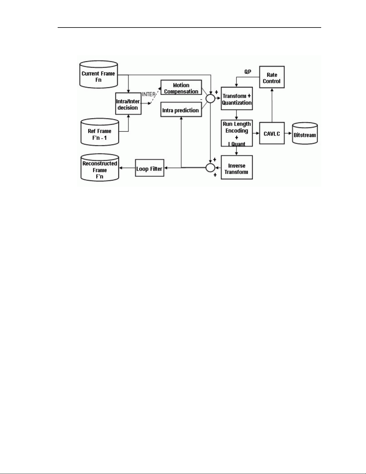
Figure 1-1 depicts the working of the H.264 Encoder algorithm.
Figure 1-1. Working of H.264 Video Encoder
In H.264 Encoder, the operations are performed on a set of specific N
macro blocks. The value of N at the most can be 2. The operations such as
Motion Compensation, Transform and Quantization, Run Length Encoding
and Inverse Quantization, and Inverse Transform Blocks are called once,
for all the inter macro blocks in the set of N.
In motion estimation, the encoder searches for the best match in the
available reference frame(s). After quantization, contents of some blocks
become zero.
The H.264 Encoder defines in-loop filtering to avoid blocks across the 4x4
block boundaries. It is the second most computational task of H.264
encoding process after motion estimation. In-loop filtering is applied on all
4x4 edges as a post-process and the operations depend on the edg e
strength of the particular edge.
The H.264 Encoder applies entropy-coding methods to use context-based
adaptivity, which improves the coding performance. All the macro blocks,
which belong to a slice, must be encoded in a raster scan order. Baselin e
profile uses the Context Adaptive Variable Length Coding (CAVLC).
CAVLC is the stage where transformed and quantized co-efficients are
entropy coded using context adaptive table switching across different
symbols. The syntax defined by the H.264 Encoder stores the information
at 4x4 block level.
1-4
From this point onwards, all references to H.264 Encoder means H.264
1080p@30 Baseline Profile Encoder only.
Page 17

1.3 Supported Services and Features
This user guide accompanies TI’s implementation of H.264 Encoder on the
DM6467 platform.
This version of the codec has the following supported features of the
standard:
eXpressDSP Digital Media (XDM 1.0 IVIDENC1) compliant
Supports YUV420 interleaved color sub-sampling (Y as a single plane
and U & V components interleaved to form the second plane) formats
Supports H.264 Baseline Profile for progressive I and P frames only
Supports multiple slices per frame conforming to H.241 requirement of
fixed bytes per slice
Supports only one motion vector per macro block
Supports rate control at row and frame level
Introduction
Supports DMA based framework
Uses C64x+, HDVICP 0, and HDVICP 1 sub-systems
The 720p quality of this encoder is not at par with the 720p encode
only solution from TI, tradeoffs have been made to get performance for
1080p at the cost of quality
1-5
Page 18

Introduction
This page is intentionally left blank
1-6
Page 19

Chapter 2
Installation Overview
This chapter provides a brief description on the system requirements and
instructions for installing the codec component. It also provides information
on building and running the sample test application.
Topic Page
2.1 System Requirements 2-2
2.2 Installing the Component 2-2
2.3 Before Building the Sample Test Application 2-5
2.4 Building and Running the Sample Test Application 2-6
2.5 Configuration Files 2-7
2.6 Uninstalling the Component 2-8
2.7 Evaluation Version 2-8
2-1
Page 20

Installation Overview
2.1 System Requirements
This section describes the hardware and software requirements for the
normal functioning of the codec component.
2.1.1 Hardware
This codec is built and tested on the DM6467 EVM only.
2.1.2 Software
The following are the software requirements for the normal functioning of
the codec:
Development Environment: This project is developed using Code
Composer Studio version 3.3.49.
Code Generation Tools: This project is compiled, assembled,
archived, and linked using the code generation tools version 6.0.8.
2.2 Installing the Component
The codec component is released as a compressed archive. To install the
codec, extract the contents of the zip file onto your local hard disk. The zip
file extraction creates a top level directory called
200_V_H264AVC_E_1_10, under which another directory named
DM6467_BP_001 is created.
Figure 2-1 shows the sub-directories created in the DM6467_BP_001
directory.
Note:
The source folders under H264Encoder (
of a library based (object code) release.
AlgSrc) is not present in case
2-2
Page 21
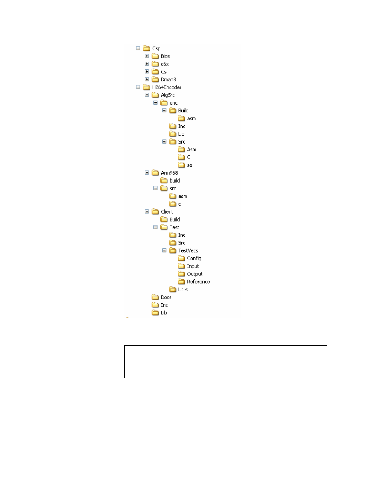
Installation Overview
Figure 2-1. Component Directory Structure
Note:
If you are installing an evaluation version of this codec, the directory
name will be 200E_V_H264AVC_E_1_10.
Table 2-1 provides a description of the sub-directories created in the
DM6467_BP_001 directory.
Table 2-1. Component Directories
Sub-Directory Description
2-3
Page 22

Installation Overview
Sub-Directory Description
Csp\Bios Contains BIOS specific files
Csp\Csl Contains CSL files
Csp\c6x Contains CSL files
Csp\Dman3 Contains DMAN3 related files
\H264Encoder\AlgSrc\enc\Build Contains the algorithm application project (.pjt) file
\H264Encoder\AlgSrc\enc\Build\asm Contains the assembly files generated by the compiler
during compilation
\H264Encoder\AlgSrc\enc\inc Contains algorithm header files
\H264Encoder\AlgSrc\enc\lib Contains the algorithm lib file generated on compilation
of the code
\H264Encoder\AlgSrc\enc\src\asm Contains algorithm source assembly files
\H264Encoder\AlgSrc\enc\src\c Contains algorithm source C files
\H264Encoder\AlgSrc\enc\src\sa Contains algorithm source linear assembly files
\H264Encoder\Arm968\build Contains the ARM968 project file
\H264Encoder\Arm968\src\asm Contains the ARM968 source assembly files
\H264Encoder\Arm968\src\c Contains the ARM968 source C files
\H264Encoder\Client\Build Contains the sample test application project (.pjt) file
\H264Encoder\Client\Test\Inc Contains header files needed for the application code
\H264Encoder\Client\Test\Src Contains application C files
\H264Encoder\Client\Test\TestVecs\Config Contains configuration parameter file
\H264Encoder\Client\Test\TestVecs\Input Contains input test vectors
\H264Encoder \Client\Test\TestVecs\Output Contains output generated by the codec
\H264Encoder\Client\Test\TestVecs\Reference Contains reconstructed outputs generated by the
encoder to verify conformance with decoder
\H264Encoder\Client\Test\Utils Folder that stores basic utilities like file compare and
YUV display executables.
\H264Encoder\Docs Contains user guide and datasheet
\H264Encoder\Inc Contains XDM related header files which allow interface
to the codec library
\H264Encoder\Lib Contains the algorithm library file
2-4
Page 23

2.3 Before Building the Sample Test Application
This codec is accompanied by a sample test application. To run the sample
test application, you need DSP/BIOS, TI Codec Engine (CE), and HDVICP
API. This version of the codec has been validated with DSP/BIOS version
5.31 . Codec Engine (CE) version 2.10.01 and HDVICP API version
1.01.017
The 1080p encoder uses both the HDVICP resources of the DM6467 to
reduce the DDR bandwidth for achieving performance. Hence,
simultaneous encode/decode is not possible with this encoder.
2.3.1 Installing DSP/BIOS
You can download DSP/BIOS from the TI external website:
https://www-a.ti.com/downloads/sds_support/targetcontent/bios/index.html
Install DSP/BIOS at the same location where you have installed Code
Composer Studio. For example:<install directory>\CCStudio_v3.3
The sample test application uses the following DSP/BIOS files:
Installation Overview
Header file, bcache.h available in the
<install directory>\CCStudio_v3.3\<bios_directory>\packages
\ti\bios\include directory.
Library file, biosDM420.a64P available in the
<install directory>\CCStudio_v3.3\<bios_directory>\packages\ti\bios\lib
directory.
Set a system environment variable named
<install directory>\CCStudio_v3.3\< bios_directory >\
2.3.2 Installing Codec Engine (CE)
Download CE version CE 2.10.01 or newer from TI external website:
https://www-a.ti.com/downloads/sds_support/targetcontent/CE/index.html
The codec uses framework components and XDAIS version that are a part
of CE 2.10.01 or newer.
1) Extract the CE zip file to the same location where the Code Composer
Studio is installed. For example: <install directory>\CCStudio_v3.3.
The test application uses the following RMAN files:
o Library file, rmand.a64P, available in the <install
directory>\CCStudio_v3.3\<ce_directory>\cetools\packages\ti\sdo\f
c\rman directory.
BIOS_INSTALL_DIR pointing to
o Header file, rman.h, available in the <install
directory>\CCStudio_v3.3
\<ce_directory>\cetools\packages\ti\sdo\fc\rman directory.
o Header file, ires.h available in the <install
directory>\CCStudio_v3.3\
<ce_directory>\cetools\packages\ti\xdais directory.
2-5
Page 24

Installation Overview
2) Set a system environment variable named
to <install directory>\CCStudio_v3.3\<ce_directory>\cetools.
3) Set a system environment variable named
pointing to <install
directory>\CCStudio_v3.3\<ce_directory>\cetools\packages\ti\xdais.
4) Set a system environment variable
to <install
directory>\CCStudio_v3.3\<ce_directory>\cetools\packages\ti\sdo\edm
a3.
2.3.3 Installing HDVICP API
Download HDVICP Library version 1.01.017
1) Extract the HDVICP API zip file to the same location where the Code
Composer Studio is installed. For example: <install
directory>\CCStudio_v3.3.
2) Set a system environment variable named HDVICP_API pointing to
<install
directory>\CCStudio_v3.3\<hdvicp>\200_V_HDVICP_X_1_01\DM6467
_X_001\hdvicp_api
FC_INSTALL_DIR pointing
XDAIS_INSTALL_DIR
EDMA3LLD_INSTALL_DIR pointing
2.4 Building and Running the Sample Test Application
The sample test application that accompanies this codec component will
run in TI’s Code Composer Studio development environment. To build and
run the sample test application in Code Composer Studio, follow these
steps:
1) Extract the .zip file from the package.
2) Verify that you have installed TI’s Code Composer Studio version
3.3.49 and code generation tools version 6.0.8. Start the Code
Composer Studio to view the Parallel Debug Manager (PDM) window.
3) In the PDM window, open the window by double clicking on ARM926,
load the GEL file davincihd_arm.gel and click Debug > Connect.
4) In the PDM window, open the window by double clicking on
C6400PLUS, load the GEL file davincihd_dsp.gel and click
Debug > Connect.
5) Open the test application project file – testh264encoderapp.pjt – in
C6400PLUS window. This file is available in the \Client\Build subdirectory.
6) Select Project > Build to build the sample test application. This
creates an executable file, TestEncoderApp.out in the \Client\Build\Out
sub-directory.
2-6
7) Select
File > Load, browse to the \Client\Build\Out sub-directory,
select the codec executable created in step 6, and load it into Code
Composer Studio in preparation for execution.
Page 25

Installation Overview
8) Select
Debug > Run to execute the sample test application.
The sample test application takes the input files stored in the \Client\Test\TestVecs\Input subdirectory, runs the codec, and uses the reference files stored in the
\Client\Test\TestVecs\Reference sub-directory to verify that the codec is functioning as
expected.
2.5 Configuration Files
This codec is shipped along with:
Encoder configuration file (configparams_1080.cfg) - contains the input
and output filenames, and the configuration parameters required for
the encoder. The configparams_1080.cfg file is available in the
\Client\Test\TestVecs\Config sub-directory.
A sample configparams_1080.cfg file is as shown.
# New Input File Format is as follows
# <ParameterName> = <ParameterValue> # Comment
###########################################################
# Parameters
###########################################################
InputFile = ..\\..\\Test\\TestVecs\\Input\\
airshow1_p1920x1088.yuv
EncodedFile = ..\\..\\Test\\TestVecs\\Output\\ airshow.264
ReconFile = ..\\..\\Test\\TestVecs\\Reference\\
airshow_recon.yuv
ImageWidth = 1920 # Image width in Pels
ImageHeight = 1088 # Image height in Pels
ImagePitch = 1920 # Input Image pitch in Pels
FrameRate = 30000 # Frame Rate per second*1000 (1-100)
BitRate = 10000000 # Bitrate(bps) #if ZERO=>> RC
is OFF
ChromaFormat = 1 # 1 => XMI_YUV_420P only
supported
IntraPeriod = 30 # Period of I-Frames
FramesToEncode = 3 # Number of frames to be coded
RC_PRESET = 1 # Rate control preset
1=>IVIDEO_LOW_DELAY
2=>IVIDEO_STORAGE
4=>IVIDEO_NONE
ENC_PRESET = 0 #Not supported : Default-0
EncodeWidth = 1920 # Encode Image width in Pels
EncodeHeight = 1088 # Encode Image height in Pels
###########################################################
# Encoder Control
###########################################################
ProfileIDC = 66 # Profile IDC (66=baseline,
77=main, 100=high)
LevelIDC = 40 # Level IDC (e.g. 20 = level 2.0)
QPISlice = 28 # Quant.param for I Slices (0-51)
QPSlice = 28 # Quant.param for non-I slices (0-51)
ChromaQPOffset = 0 # Chroma QP offset (-12..12)
SecChromaQPOffset = 0 # Second Chroma QP offset (-12..12)
EntropyCodingMode = 0 # CAVLC = 0 , CABAC = 1
RateCtrlQpMax = 44 # Qp range max for Rate Control
2-7
Page 26

Installation Overview
(Max: 51)
RateCtrlQpMin = 10 # Qp range min for Rate Control
(Min: 0)
NumRowsInSlice = 0 # Number of rows in a Slice
(0..Max no. of rows in the frame)
sliceMode = 2 # 0 = No slice 2 = Slice based on
packet size
sliceUnitSize = 1500 # Maximum size of the slice to be
encoded
AdaptiveIntraRefresh = 0 # Disabled => 0
InputContentType = 0 #PROGRESSIVE = 0 INTERLACED = 1
PicAFFFlag = 0 # PicAFF Enable Flag
InterlaceReferenceMode = 1 # 0 = Only top field Default,
1 = same parity field,
2 = most recently coded frame,
3 = Adaptive reference field
Transform8x8DisableFlag = 1 # 0 = Enabled, 1 = Disabled
Intra8x8EnableFlag = 0 # 0 = NONE, 1 = I Frame, 2 = P, 3 =
IP
Intra4x4EnableFlag = 3 # 0 = NONE, 1 = I Frame, 2 = P, 3 =
IP
ChromaConversionMode = 1 # 0 = line drop, 1 = Average
##########################################################
# Loop filter parameters
###########################################################
LoopFilterDisable = 0 # Disable loop filter in slice
header (0=Filter, 1=No Filter,
2= Disable filter
across slice boundary)
LoopFilterAlphaC0Offset = 0 # Alpha & C0 offset div. 2, { 6, -5, ... 0, +1, .. +6}
LoopFilterBetaOffset = 0 # Beta offset div. 2, {-6, -5,
... 0, +1, .. +6}
2.6 Uninstalling the Component
To uninstall the component, delete the codec directory from your hard disk.
2.7 Evaluation Version
If you are using an evaluation version of this codec, there will be a limit of
encoding up to 54000 frames in the usage of the encoder.
2-8
Page 27

Chapter 3
Sample Usage
This chapter provides a detailed description of the sample test application
that accompanies this codec component.
Topic Page
3.1 Overview of the Test Application 3-2
3.2 Handshaking Between Application and Algorithm 3-7
3.3 Sample Test Application 3-9
3-1
Page 28

Sample Usage
3.1 Overview of the Test Application
The test application exercises the IH264FHDVENC_Params extended class
of the H264 Encoder library. The main test application files are
TestEncoderApp.c and TestEncoderApp.h. These files are available in the
\Client\Test\Src and \Client\Test\Inc sub-directories respectively.
Figure 3-1 depicts the sequence of APIs exercised in the sample test
application.
Figure 3-1. Test Application Sample Implementation
3-2
Page 29

The test application is divided into four logical blocks:
Parameter setup
Algorithm instance creation and initialization
Process call
Algorithm instance deletion
3.1.1 Parameter Setup
Each codec component requires various codec configuration pa rameters to
be set at initialization. For example, a video codec requires parameters
such as video height, video width, etc. The test application obtains the
required parameters from the Encoder configuration files.
In this logical block, the test application does the following:
1) Opens the configuration file, configparams_1080.cfg and reads the
input file name, and output/reference file name, and the various
configuration parameters required for the algorithm.
Sample Usage
For more details on the configuration files, see Section
2)
Sets the IVIDENC1_Params structure based on the values it reads
2.5.
from the configparams_1080.cfg file.
3) Reads the input bit-stream into the application input buffer.
After successful completion of the above steps, the test application does
the algorithm instance creation and initialization.
3.1.2 Algorithm Instance Creation and Initialization
In this logical block, the test application accepts the various initialization
parameters and returns an algorithm instance pointer. The following APIs
are called in a sequence:
1) algNumAlloc() - To query the algorithm about the number of memory
records it requires.
2) algAlloc() - To query the algorithm about the memory requirement
to be filled in the memory records.
3) algInit() - To initialize the algorithm with the memory structures
provided by the application.
A sample implementation of the create function that calls
algAlloc(), and algInit() in a sequence is provided in the
ALG_create() function implemented in the alg_create.c file.
algNumAlloc(),
After successful creation of the algorithm instance, the test application
does DMA and HDVICP Resource allocation for the algorithm. This
requires initialization of Resource Manager Module (RMAN) and grant of
DMA and HDVICP resources. This is implemented by calling the RMAN
interface functions in the following sequence:
3-3
Page 30

Sample Usage
3.1.3 Process Call
1) RMAN_init() – To initialize the RMAN module.
RMAN_register() – To register the HDVICP protocol/resource
2)
manager with the generic resource manager.
RMAN_assignResources() – To register resources to the algorithm as
3)
requested HDVICP protocol/resource manager with the generic reso urce
manager.
Note:
RMAN function implementations are provided in rmand.a64P library.
After algorithm instance creation and initialization, the test application does
the following:
1) Sets the dynamic parameters (if they change during run-time) by
calling the
control() function with the XDM_SETPARAMS command.
2) Sets the input and output buffer descriptors required for the
process() function call. The input and output buffer descriptors are
obtained by calling the
control() function with the XDM_GETBUFINFO
command.
3) Calls the process() function to encode a single frame of data. The
behavior of the algorithm can be controlled using various dynamic
parameters (see Section
4.2.1.11). The inputs to the process function
are input and output buffer descriptors, pointer to the
IVIDENC1_InArgs and IVIDENC1_OutArgs structures.
4) On calling the process() function to encode a single frame of data,
the video task can be put to SEM-pend state using semaphores after
triggering the start of the encode/decode frame start. On receipt of
interrupt signal for the end of frame encode/decode, the application
should release the semaphore and resume the video task which will do
any book-keeping operations by the codec and updating the output
parameters structure -
IVIDENC1_OutArgs.
3-4
Page 31

Host
System
application
Process call frame n
Sample Usage
Interrupt between
HDVICP and Host
Process call frame n+1
Transfer of
tasks at Host
Host Video
Task
HDVICP
Tasks
MB level tasks for
frame n
Figure 3-2. Process Call with Host Release
Note:
The process call returns the control to the application after the initial
setup related tasks are completed
Application can schedule a different task to use the freed up Host
resource
All service requests from HDVICP are handled via interrupts
Application resumes the suspended process call after the last
service request for HDVICP has been handled
Application can now complete concluding portions of the process
call and return
The control() and process() functions should be called only within the
scope of the
which activate and deactivate the algorithm instance respectively. Once an
algorithm is activated, there could be any ordering of
process() functions. The following APIs are called in a sequence:
algActivate() and algDeactivate() XDAIS functions
MB level tasks for
frame n+1
Host system
tasks
HDVICP Busy
control() and
1)
algActivate() - To activate the algorithm instance.
control() (optional) - To query the algorithm on status or setting of
2)
dynamic parameters etc., using the seven available control commands.
3)
process() - To call the Encoder with appropriate input/output buffer
and arguments information.
4) control() (optional) - To query the algorithm on status or setting of
dynamic parameters etc., using the seven available control commands.
5)
algDeactivate() - To deactivate the algorithm instance.
6) The do-while loop encapsulates frame level process() call and
updates the input buffer pointer every time before the next call. The dowhile loop breaks off either when an error condition occurs or when the
encoding of the required number of frames is completed. It also
protects the
process() call from file operations by placing appropriate
3-5
Page 32

Sample Usage
calls for cache operations as well. The test application does a cache
invalidate for the valid input buffers before
write back invalidate for output buffers after
In the sample test application, after calling algDeactivate(), the output
data is dumped to a file.
3.1.4 Algorithm Instance Deletion
Once decoding/encoding is complete, the test application must release the
memory. The following APIs are called in sequence:
1) algNumAlloc() - To query the algorithm about the number of
memory records it used.
2)
algFree() - To query the algorithm to get the memory record
information.
process() and a cache
process().
A sample implementation of the delete function that calls
algNumAlloc()
and algFree() in a sequence is provided in the ALG_delete() function
implemented in the alg_create.c file.
After successful execution of the algorithm, the test application frees up the
DMA and HDVICP Resource allocated for the algorithm. This is
implemented by calling the RMAN interface functions in the following
sequence:
1)
RMAN_freeResources () - To free the resources that were allocated
to the algorithm before process call.
2) RMAN_unregister() – To unregister the HDVICP protocol/resource
manager with the generic resource manager.
3)
RMAN_exit() - To delete the generic IRES RMAN and release
memory.
3-6
Page 33

3.2 Handshaking Between Application and Algorithm
Application provides the algorithm with its implementation of functions for
the video task to move to SEM-pend state, when the execution happens in
the co-processor. The algorithm calls these application functions to move
the video task to SEM-pend state.
Framework Provided HDVICP Callback APIs
int _doneSemaphore;
HDVICP_start(handle, hdVicpHandle, ISRFunction)
{
installNonBiosISR ( handle, hdvicpHandle, ISRFunction
);
}
HDVICP_wait(handle, hdVicpHandle)
{
SEM_pend(_doneSemaphore);
}
HDVICP_done(handle, hdVicpHandle) {
SEM_post(_doneSemaphore)
}
Sample Usage
Codec
#include <…/ires_hdvicp.h>
void _MyCodecISRFunction();
MYCODEC::IVIDENC1::process()
{
// …. set up for frame encode
HDVICP_configure(h264venc, h264venc ->hdvicpHandle,
H264VENCISRFunction);
// … Hand over the DSP to application
HDVICP_wait(h264venc, h264venc->hdvicpHandle);
// Release of HOST
…. End of frame processing
process ()
}
void H264VENCISRFunction(IALG_Handle handle)
{ H264VENC_TI_Obj * h264venc = (void *)handle;
HDVICP_done(h264venc, h264venc->hdvicpHandle);
Figure 3-3. Interaction between Application and Codec.
Note:
Process call architecture to share Host resource among multiple
threads
ISR ownership is with the Host layer resource manager – outside the
codec
The actual codec routine to be executed during ISR is provided by
3-7
Page 34

Sample Usage
the codec
related calls (SEM_pend, SEM_post) are also
OS/System
performed outside the codec
ndependent
Codec implementation is OS i
T are:
he functions to be implemented by applications
HDVICP_initHandle(void *hdvicpHandle)
1)
This is the top-level f ful when
HDVICP_Wait and HDVICP_Done functions are called by algorithm.
This function is called by m to register its ISR function, which the application needs to
unction, which initializes hdvicp handle that will be use
HDVICP_configure(IALG_Handle handl
2)
*hdvicpHandle, void (*ISRfunctionptr)(IALG_Handle
handle)
)
e, void
the algorith
call when it receives interrupts pertaining to the video task.
HDVICP_wait (void *hdvicpHan
3)
This function is calle pend state.
This function is calle M-pend state.
d by the algorithm to put the video task in SEM-
HDVICP_done (void *hdvicpHandle)
4)
d by algorithm to release the video task from SE
In the sample test application, these functions are implemented
hdvicp_framework.c file using polling. The application can impleme
dle)
in
nt it in
its own way considering the underlying system.
3-8
Page 35

3.3 Sample Test Application
The test application exercises the IH264FHDVENC_Params extended class
of the H.264 Encoder.
Table 3-1. Process ( ) Implementation.
/* Main Function acting as a client for Video Encode Call*/
H264VENC_setinitparams (¶ms);
H264VENC_setrunparams (&dynamicparams);
HDVICP_initHandle(&hdvicpObj);
/*---------------- Encoder creation -----------------*/
handle = (IALG_Handle) h264VENC_create();
/*-------------- Get Buffer information -------------*/
H264VENC_control(handle, XDM_GETBUFINFO);
/*-Do-While Loop for Encode Call for a given stream-*/
do
{
/* Read the Input Frame in the Application Input Buffer */
validBytes = ReadInputData(inFile);
/* Optional: Set Run time parameters in the Algorithm via
control() */
h264VENC_control(handle, XDM_SETPARAMS);
/*------ Start the process to start encoding a frame.----*/
retVal = h264VENC_encode
(
handle,
(IVIDEO1_BufDescIn *)&inputBufDesc,
(XDM_BufDesc *)&outputBufDesc,
(IVIDENC1_InArgs *)&inArgs,
(IVIDENC1_OutArgs *)&outArgs
);
/* Get the status of the encoder using control call */
h264VENC_control(handle, XDM_GETSTATUS);
} while(1);
//End of Do-While loop - which encodes frames.
ALG_delete (handle);
Sample Usage
Note:
This sample test application does not depict the actual function
parameter or control code. It shows the basic flow of the code.
3-9
Page 36

Sample Usage
This page is intentionally left blank
3-10
Page 37

Chapter 4
API Reference
This chapter provides a detailed description of the data structures a nd
interfaces functions used in the codec component.
Topic Page
4.1 Symbolic Constants and Enumerated Data Types 4-2
4.2 Data Structures 4-9
4.3 Interface Functions 4-30
4-1
Page 38

API Reference
4.1 Symbolic Constants and Enumerated Data Types
This section summarizes all the symbolic constants specified as either
#define macros and/or enumerated C data types. For each symbolic
constant, the semantics or interpretation of the same is also provided
Table 4-1. List of Enumerated Data Types
Group or Enumeration Class Symbolic Constant Name Description or Evaluation
IVIDEO_FrameType
IVIDEO_NA_FRAME
IVIDEO_I_FRAME
IVIDEO_P_FRAME
IVIDEO_B_FRAME
IVIDEO_IDR_FRAME
IVIDEO_II_FRAME
IVIDEO_IP_FRAME
IVIDEO_IB_FRAME
Frame type not available
Intra coded frame
Forward inter coded frame
Bi-directional inter coded frame.
Not supported in this version of
H264 encoder.
Intra coded frame that can be used
for refreshing video content
Interlaced frame, both fields are I
frames.
Not supported in this version of
H264 Encoder.
Interlaced frame, first field is an I
frame, second field is a P frame.
Not supported in this version of
H264 Encoder.
Interlaced frame, first field is an I
frame, second field is a B frame.
Not supported in this version of
H264 Encoder.
4-2
IVIDEO_PI_FRAME
IVIDEO_PP_FRAME
IVIDEO_PB_FRAME
IVIDEO_BI_FRAME
Interlaced frame, first field is a P
frame, second field is a I frame.
Not supported in this version of
H264 Encoder.
Interlaced frame, both fields are P
frames.
Not supported in this version of
H264 Encoder.
Interlaced frame, first field is a P
frame, second field is a B frame.
Not supported in this version of
H264 Encoder.
Interlaced frame, first field is a B
frame, second field is an I frame.
Not supported in this version of
H264 Encoder.
Page 39

API Reference
Group or Enumeration Class Symbolic Constant Name Description or Evaluation
IVIDEO_BP_FRAME
IVIDEO_BB_FRAME
IVIDEO_MBAFF_I_FRAME
IVIDEO_MBAFF_P_FRAME
IVIDEO_MBAFF_B_FRAME
IVIDEO_MBAFF_IDR_FRAME
Interlaced frame, first field is a B
frame, second field is a P frame.
Not supported in this version of
H264 Encoder.
Interlaced frame, both fields are B
frames.
Not supported in this version of
H264 Encoder.
Intra coded MBAFF frame.
Not supported in this version of
H264 Encoder
Forward inter coded MBAFF frame.
Not supported in this version of
H264 Encoder
Bi-directional inter coded MBAFF
frame.
Not supported in this version of
H264 Encoder.
Intra coded MBAFF frame that can
be used for refreshing video content.
Not supported in this version of
H264 Encoder.
IVIDEO_ContentType
IVIDEO_FRAMETYPE_DEFAU
LT
IVIDEO_CONTENTTYPE_NA
IVIDEO_PROGRESSIVE
IVIDEO_PROGRESSIVE_FRA
ME
IVIDEO_INTERLACED
IVIDEO_INTERLACED_FRAM
E
IVIDEO_INTERLACED_TOPF
IELD
IVIDEO_INTERLACED_BOTT
OMFIELD
IVIDEO_CONTENTTYPE_DEF
AULT
Default is set to IVIDEO_I_FRAME
Content type is not applicable
Progressive video content
Progressive video content
Interlaced video content.
Not supported in this version of
H264 Encoder.
Interlaced video content.
Not supported in this version of
H264 Encoder.
Interlaced picture, top field.
Not supported in this version of
H264 Encoder.
Interlaced picture, bottom field.
Not supported in this version of
H264 Encoder.
Default value is set to
IVIDEO_PROGRESSIVE
IVIDEO_RateControlPreset IVIDEO_NONE
No rate control is used
4-3
Page 40

API Reference
Group or Enumeration Class Symbolic Constant Name Description or Evaluation
IVIDEO_SkipMode
IVIDEO_LOW_DELAY
IVIDEO_STORAGE
IVIDEO_TWOPASS
IVIDEO_USER_DEFINED
IVIDEO_RATECONTROLPRES
ET_DEFAULT
IVIDEO_FRAME_ENCODED
Constant Bit Rate (CBR) control for
video conferencing.
PLR3 rate control algorithm is used
in CBR.
This is the default value.
Variable Bit Rate (VBR) control for
local storage (DVD) recording.
PLR4 rate control algorithm is used
in VBR.
Two pass rate control for non real
time applications.
Not supported in this version of
H264 Encoder.
User defined configuration using
advanced parameters.
Not supported in this version of
H264 Encoder.
Default value is set to
IVIDEO_LOW_DELAY.
Not supported in this version of
H264 Encoder.
Input content encoded
XDM_DataFormat
IVIDEO_FRAME_SKIPPED
IVIDEO_SKIPMODE_DEFAUL
T
XDM_BYTE
XDM_LE_16
XDM_LE_32
XDM_LE_64
XDM_BE_16
XDM_BE_32
Input content skipped, that is, not
encoded
Default value is set to
IVIDEO_FRAME_ENCODED.
Big endian stream (default value).
Not supported in this version of
H264 Encoder.
16-bit little endian stream.
Not supported in this version of
H264 Encoder.
32-bit little endian stream
64-bit little endian stream.
Not supported in this version of
H264 Encoder.
16-bit big endian stream.
Not supported in this version of
H264 Encoder.
32-bit big endian stream.
Not supported in this version of
H264 Encoder.
4-4
Page 41

API Reference
Group or Enumeration Class Symbolic Constant Name Description or Evaluation
XDM_ChromaFormat
XDM_BE_64
XDM_CHROMA_NA
XDM_YUV_420P
XDM_YUV_422P
XDM_YUV_422IBE
XDM_YUV_422ILE
XDM_YUV_444P
XDM_YUV_411P
64-bit big endian stream.
Not supported in this version of
H264 Encoder.
Chroma format is not applicable
YUV 4:2:0 planar
YUV 4:2:2 planar.
YUV 4:2:2 interleaved (big endian).
Not supported in this version of
H264 Encoder.
YUV 4:2:2 interleaved (little endian).
This is the default value.
Not supported in this version of
H264 Encoder.
YUV 4:4:4 planar.
Not supported in this version of
H264 Encoder.
YUV 4:1:1 planar.
Not supported in this version of
H264 Encoder.
XDM_CmdId
XDM_GRAY
XDM_RGB
XDM_CHROMAFORMAT_DEFAU
LT
XDM_GETSTATUS
XDM_SETPARAMS
XDM_RESET
XDM_SETDEFAULT
Gray format.
Not supported in this version of
H264 Encoder.
RGB color format.
Not supported in this version of
H264 Encoder.
Default value is set to
XDM_YUV_422ILE.
Query algorithm instance to fill
Status structure
Set run-time dynamic parameters
via the
DynamicParams structure
Reset the algorithm
Initialize all fields in Params
structure to default values specified
in the library
Not supported in this version of
H264 Encoder.
4-5
Page 42

API Reference
Group or Enumeration Class Symbolic Constant Name Description or Evaluation
XDM_EncodingPreset
XDM_FLUSH
XDM_GETBUFINFO
XDM_GETVERSION
XDM_DEFAULT
XDM_HIGH_QUALITY
XDM_HIGH_SPEED
Handle end of stream conditions.
This command forces algorithm
instance to output data without
additional input.
Not supported in this version of
H264 Encoder.
Query algorithm instance regarding
the properties of input and output
buffers
Query the version of the algorithm
Not supported in this version of
H264 Encoder.
Default setting of the algorithm
specific creation time parameters.
Set algorithm specific creation time
parameters for high quality (default
setting)
Not supported in this version of
H264 Encoder.
Set algorithm specific creation time
parameters for high speed
Not supported in this version of
H264 Encoder.
XDM_EncMode
XDM_ErrorBit
XDM_USER_DEFINED
XDM_ENCODE_AU
XDM_GENERATE_HEADER
XDM_APPLIEDCONCEALMENT
XDM_INSUFFICIENTDATA
XDM_CORRUPTEDDATA
XDM_CORRUPTEDHEADER
User defined configuration using
advanced parameters
Not supported in this version of
H264 Encoder.
Encode entire access unit (default
value).
Encode only header
Bit 9
1 - Applied concealment
0 - Ignore
Bit 10
1 - Insufficient data
0 - Ignore
Bit 11
1 - Data problem/corruption
0 - Ignore
Bit 12
1 - Header problem/corruption
0 - Ignore
4-6
Page 43

API Reference
Group or Enumeration Class Symbolic Constant Name Description or Evaluation
XDM_UNSUPPORTEDINPUT
XDM_UNSUPPORTEDPARAM
XDM_FATALERROR
Bit 13
1 - Unsupported
0 - Ignore
Bit 14
1 - Unsupported input
0 - Ignore
Bit 15
1 - Fatal error (stop encoding)
0 - Recoverable error
Note:
The remaining bits that are not mentioned in
interpreted as:
Bit 16-32:Reserved
Bit 8: Reserved
Bit 0-7:Codec and implementation specific
feature/parameter in input
parameter or configuration
XDM_ErrorBit are
Bit 0
1 - There is an overflow of the out put buffer allocated by the
application
0 - Ignore
Bit 1
1 - The encoding of an MB pair exceeds the sliceUnitSize set by
the application
0 - Ignore
The algorithm can set multiple bits to 1 depending on the error condition.
Table 4-2. H264 Encoder Specific Enumerations.
Group or Enumeration Class Symbolic Constant Name Description or Evaluation
IH264ENC_MetaDataId
IH264FHDVENC_SliceCoding
Preset
METADATA_NALU_INFO
METADATA_MB_INFO
IH264_SLICECODING_DEFA
ULT
IH264_SLICECODING_USER
DEFINED
Meta data containing the information
about slice size
Meta data containing the information
about each macro block
0: Default slice coding params.
1: User defined slice coding params.
Not supported in this version of
H264 Encoder
4-7
Page 44

API Reference
Group or Enumeration Class Symbolic Constant Name Description or Evaluation
IH264FHDVENC_SliceMode
IH264_SLICECODING_EXIS
TING
IH264_SLICECODING_MAX
IH264_SLICEMODE_NONE
IH264_SLICEMODE_MBUNIT
IH264_SLICEMODE_BYTES
IH264_SLICEMODE_OFFSET
IH264_SLICEMODE_DEFAUL
T
IH264_SLICEMODE_MAX
2: Keep the slice coding params as
existing. Reserved for future use
3: Reserved for future use
0: No multiple slices
Default setting
1: Slices are controlled based on the
number of macro blocks.
Not supported in this version of
H264 Encoder
2: Slices are controlled based on
number of bytes
3: Slices are controlled based on
user defined offset in unit of rows.
Not supported in this version of
H264 Encoder
Default slice coding mode single
slice.
Not supported in this version of
H264 Encoder
Reserved for future use
IH264FHDVENC_StreamForma
t
IH264_BYTE_STREAM
IH264_NALU_STREAM
IH264_STREAM_FORMAT_DE
FAULT
IH264_STREAM_FORMAT_MA
X
0: bit-stream contains the start code
identifier
1: bit-stream does not contain the
start code identifier
Not supported in this version of
H264 Encoder.
Default slice coding mode is bytestream. Default is
IH264_BYTE_STREAM
Not supported in this version of
H264 Encoder
Reserved for future use
4-8
Page 45

4.2 Data Structures
This section describes the XDM defined data structures that are common
across codec classes. These XDM data structures can be extended to
define any implementation specific parameters for a codec component.
4.2.1 Common XDM Data Structures
This section includes the following common XDM data structures:
XDM_BufDesc
XDM1_BufDesc
XDM_SingleBufDesc
XDM1_SingleBufDesc
XDM_AlgBufInfo
IVIDEO_BufDesc
API Reference
IVIDEO1_BufDesc
IVIDEO1_BufDescIn
IVIDENC1_Fxns
IVIDENC1_Params
IVIDENC1_DynamicParams
IVIDENC1_InArgs
IVIDENC1_Status
IVIDENC1_OutArgs
IVIDENC1_MbData
4-9
Page 46

API Reference
4.2.1.1 XDM_BufDesc
║ Description
This structure defines the buffer descriptor for input and output buffers.
║ Fields
Field Datatype Input/
Output
Description
**bufs XDAS_Int8
numBufs XDAS_Int32
*bufSizes XDAS_Int32
Input Pointer to the vector containing buffer addresses
Input Number of buffers
Input Size of each buffer in bytes
4.2.1.2 XDM1_BufDesc
║ Description
This structure defines the buffer descriptor for input and output buffers.
║ Fields
Field Datatype Input/
Output
numBufs XDAS_Int32
descs[XDM_MA
XDM1_SingleBufDesc
Input Number of buffers
Input Array of buffer descriptors
Description
X_IO_BUFFERS
]
4.2.1.3 XDM_SingleBufDesc
║ Description
This structure defines the buffer descriptor for single input and output buffers.
║ Fields
Field Datatype Input/
Output
*bufs XDAS_Int8
bufSize XDAS_Int32
Input Pointer to the buffer
Input Size of the buffer in bytes
Description
4-10
Page 47

4.2.1.4 XDM1_SingleBufDesc
║ Description
This structure defines the buffer descriptor for single input and output buffers.
║ Fields
Field Datatype Input/
Output
Description
API Reference
*bufs XDAS_Int8
bufSize XDAS_Int32
accessMask XDAS_Int32
Input Pointer to the buffer
Input Size of the buffer in bytes
Output If the buffer was not accessed by the algorithm
processor (for example, it was filled by DMA or other
hardware accelerator that does not write through the
algorithm CPU), then bits in this mask should not be
set.
4.2.1.5 XDM_AlgBufInfo
║ Description
This structure defines the buffer information descriptor for input and output
buffers. This structure is filled when you invoke the
with the
║ Fields
XDM_GETBUFINFO command.
Field Datatype Input/
Output
minNumInBufs XDAS_Int32
minNumOutBufs XDAS_Int32
Output Number of input buffers
Output Number of output buffers
Description
control() function
minInBufSize[XDM_
MAX_IO_BUFFERS]
minOutBufSize[XDM
_MAX_IO_BUFFERS]
XDAS_Int32
XDAS_Int32
Output Size in bytes required for each input buffer
Output Size in bytes required for each output buffer
Note:
For H.264 Encoder, the buffer details are:
Number of input buffers required is 2 for YUV420P
Number of output buffer required is 1
The input buffer sizes (in bytes) for 1080i format are:
For YUV 420:
Y buffer = 1920 * 1088
UV buffer = 1920 * 544
4-11
Page 48

API Reference
There is no restriction on output buffer size except that it should
contain atleast one frame of encoded data.The output buffer size
can be set using the dynamic parameter at the run-time.
These are the maximum buffer sizes but you can reconfigure depending
on the input format.
For H.241 support, two output buffers are required. One buffer is used to
output the bit-stream and in the other buffer, the encoder will output the
meta data related to the slices encoded. See
structure.
4.2.1.6 IVIDEO_BufDesc
║ Description
This structure defines the buffer descriptor for input and output buffers.
║ Fields
IH264VENC_OutArgs data
Field Datatype Input/
Output
numBufs XDAS_Int32
width XDAS_Int32
*bufs[XDM_MAX_IO_BUFFERS] XDAS_Int8
bufSizes[XDM_MAX_IO_BUFFERS] XDAS_Int32
Input Number of buffers
Input Padded width of the video data
Input Pointer to the vector containing
Input Size of each buffer in bytes
Description
buffer addresses
4.2.1.7 IVIDEO1_BufDesc
║ Description
This structure defines the buffer descriptor for input and output buffers.
║ Fields
Field Datatype Input/
Output
numBufs XDAS_Int32
Input Number of buffers
Description
frameWidth XDAS_Int32
frameHeight XDAS_Int32
framePitch XDAS_Int32
bufDesc[IVIDEO_MAX_YUV_BUF
FERS]
XDM1_Singl
eBufDesc
extendedError XDAS_Int32
4-12
Input Width of the video frame
Input Height of the video frame
Input Frame pitch used to store the frame
Input Pointer to the vector containing
buffer addresses
Input Extended error field
Page 49

API Reference
Field Datatype Input/
Output
frameType XDAS_Int32
topFieldFirstFlag XDAS_Int32
repeatFirstFieldFlag XDAS_Int32
frameStatus XDAS_Int32
Input See IVIDEO_FrameType
Input Flag to indicate when the application
Input Flag to indicate when the first field
Input See
Description
enumeration
should display the top field first.
Not supported in this version of H264
Encoder.
should be repeated.
Not supported in this version of H264
Encoder
IVIDEO_OutputFrameStatus
enumeration
repeatFrame XDAS_Int32
contentType XDAS_Int32
Input Number of times the display process
needs to repeat the displayed
progressive frame.
Not supported in this version of H264
Encoder
Input Content type of the buffer
chromaFormat XDAS_Int32
Input See XDM_ChromaFormat
enumeration
4.2.1.8 IVIDEO1_BufDescIn
║ Description
This structure defines the buffer descriptor for input buffers.
║ Fields
Field Datatype Input/
Output
numBufs XDAS_Int32
frameWidth XDAS_Int32
frameHeight XDAS_Int32
framePitch XDAS_Int32
bufDesc[IVIDEO_MAX_YUV_BUF
FERS]
XDM1_Singl
eBufDesc
Input Number of buffers
Input Width of the video frame
Input Height of the video frame
Input Frame pitch used to store the frame
Input Pointer to the vector containing
Description
buffer addresses
4-13
Page 50

API Reference
4.2.1.9 IVIDENC1_Fxns
║ Description
This structure contains pointers to all the XDAIS and XDM interface
functions.
║ Fields
Field Datatype Input/
Output
Description
ialg IALG_Fxns
*process XDAS_Int32
*control XDAS_Int32
Input Structure containing pointers to all the XDAIS
interface functions.
For more details, see TMS320 DSP Algorithm
Standard API Reference (literature number
SPRU360).
Input Pointer to the process() function.
Input Pointer to the control() function.
4.2.1.10 IVIDENC1_Params
║ Description
This structure defines the creation parameters for an algorithm instance
object. Set this data structure to
NULL, if you are not sure of the values to
be specified for these parameters.
║ Fields
Field Datatype Input/
Output
size XDAS_Int32
Input Size of the basic or extended (if being used)
Description
data structure in bytes.
encodingPreset XDAS_Int32
rateControlPreset XDAS_Int32
4-14
Input Encoding preset. See
XDM_EncodingPreset enumeration for
details.
Not supported in this version of H264
Encoder.
Default :
Input Rate control preset:
Only
IVIDEO_STORAGE
presets are supported.
See IVIDEO_RateControlPreset
enumeration for details.
Default :
XDM_DEFAULT
IVIDEO_LOW_DELAY,
, IVIDEO_NONE
IVIDEO_LOW_DELAY
Page 51

API Reference
Field Datatype Input/
Output
maxHeight XDAS_Int32
maxWidth XDAS_Int32
maxFrameRate XDAS_Int32
maxBitRate XDAS_Int32
dataEndianness XDAS_Int32
Input Maximum video height to be supported in
Input Maximum video width to be supported in
Input Maximum frame rate in fps * 1000 to be
Input Maximum bit-rate to be supported in bits per
Input Endianness of input data. See
Description
pixels.
Default : 1088
Minimum: 288
Note: Only resolutions that are multiples of 2
are supported.
pixels.
Default: 1920
Minimum: 352
Note: Only resolutions that are multiples of 2
are supported.
supported.
Default: 30000
second.
Default: 10000000
XDM_DataFormat enumeration for details.
Default:
Only the default value XDM_LE_32 is
supported.
XDM_LE_32
maxInterFrameInterval XDAS_Int32
inputChromaFormat XDAS_Int32
inputContentType XDAS_Int32
reconChromaFormat XDAS_Int32
Input Distance from I-frame to P-frame:
1 - If no B-frames
2 - To insert one B-frame
Not supported in this version of H264
Encoder.
Default: 0
Input Input chroma format. See
XDM_ChromaFormat enumeration for
details.
Default: XDM_YUV_420P
Input Input content type. See
IVIDEO_ContentType enumeration for
details.
The default value
is only supported.
Input Chroma formats for the reconstruction
buffers. See
enumeration for details.
The default value
supported.
IVIDEO_PROGRESSIVE
XDM_ChromaFormat
XDM_YUV_420P is only
4-15
Page 52

API Reference
Note:
For the supported maxBitRate values, see Table A.1 – Level limits
in ISO/IEC 14496-10.
The following fields of
IVIDENC1_Params data structure are level
dependent:
maxHeight
maxWidth
maxFrameRate
maxBitRate
To check the values supported for maxHeight and maxWidth use the
following expression:
maxFrameSizeinMbs >= (maxHeight*maxWidth) / 256;
See Table A.1 – Level limits in ISO/IEC 14496-10 for the supported
maxFrameSizeinMbs values.
For example, consider you have to check if the following values are
supported for level 4.0:
maxHeight = 1088
maxWidth = 1920
The supported maxFrameSizeinMbs value for level 4.0 as per Table A.1
– Level limits is 8192.
Compute the expression as:
4-16
maxFrameSizeinMbs >= (1920*1088) / 256
The value of
true. Therefore, the above values of
maxFrameSizeinMbs is 8160 and hence the condition is
maxHeight and maxWidth are
supported for level 4.0.
Use the following expression to check the supported
maxFrameRate
values for each level:
maxFrameRate <= maxMbsPerSecond / FrameSizeinMbs;
See Table A.1 – Level Limits in ISO/IEC 14496-10 for the supported
values of
Use the following expression to calculate
maxMbsPerSecond.
FrameSizeinMbs:
FrameSizeinMbs = (inputWidth * inputHeight) / 256;
When the rate control preset is configured to IVIDEO_LOW_DELAY
(CBR mode), the encoder can skip frames, and the encoder does not
support any SEI messages in the bit-stream to indicate the frame skip.
Page 53

4.2.1.11 IVIDENC1_DynamicParams
║ Description
This structure defines the run-time parameters for an algorithm instance
object.
║ Fields
Field Datatype Input/
Output
Description
API Reference
size XDAS_Int32
inputHeight XDAS_Int32
inputWidth XDAS_Int32
refFrameRate XDAS_Int32
targetFrameRate XDAS_Int32
targetBitRate XDAS_Int32
Input Size of the basic or extended (if being used) data
structure in bytes.
Input Height of input frame in pixels
Minimum Height Supported: 288
Note: Only resolutions that are multiples of 2are
supported.
Input Width of input frame in pixels.
Minimum Width Supported: 352
Note: Only resolutions that are multiples of 2 are
supported.
Input Reference or input frame rate in fps * 1000. For
example, if the frame rate is 30, set this field to
30000.
Default : 30000
Input Target frame rate in fps * 1000. For example, if
the frame rate is 30, set this field to 30000.
Default: 30000
Input Target bit-rate in bits per second. For example, if
the bit-rate is 2 Mbps, set this field to 2097152.
Default: 1000000
intraFrameInterval XDAS_Int32
generateHeader XDAS_Int32
captureWidth XDAS_Int32
Input Interval between two consecutive intra frames.
0 - Only the first frame is intra and the rest of
all the encoded frames are inter frames
1 - No inter frames (all intra frames)
n - Intra frame after 'n-1 inter frames
Input Encode entire access unit or only header. See
XDM_EncMode enumeration for details.
Default:
Input If the field is set to:
0 - Encoded image width is used as pitch.
Any non-zero value, capture width is used
Default: 0
Not supported in this version of H264 Encoder.
XDM_ENCODE_AU
as pitch (if capture width is greater than
image width).
4-17
Page 54

API Reference
Field Datatype Input/
Output
forceFrame XDAS_Int32
Input Force the current (immediate) frame to be
Description
encoded as a specific frame type.
Supports only IVIDEO_NA_FRAME,
IVIDEO_I_FRAME and IVIDEO_IDR_FRAME
frame types.
IVIDEO_FrameType enumeration for
See
details
Default: IVIDEO_NA_FRAME
interFrameInterval XDAS_Int32
mbDataFlag XDAS_Int32
Input Number of B frames between two reference
frames; that is, the number of B frames between
two P frames or I/P frames.
Not supported in this version of H264 Encoder.
Default: 0
Input Flag to indicate that the algorithm should use MB
data supplied in additional buffer within
Not supported in this version of H264 Encoder.
Default: 0
Note:
The following are the limitations on the parameters of
IVIDENC1_DynamicParams data structure:
inputHeight <= maxHeight
inputWidth <= maxWidth
refFrameRate <= maxFrameRate
targetFrameRate <= maxFrameRate
targetBitRate <= maxBitRate
inBufs.
4-18
The rate control used in H.264 Encoder can work for a target bit-rate of a
minimum of 32 kbps and a maximum of 10 mbps up to level 3. However,
the recommended range varies with the format. For example, for NTSC
D1, the recommended range is 1.5 mbps to 6.0 mbps.
The bit-rate achieved by the encoder may deviate largely from the
value
specified by the targetBitRate field of the
IVIDENC1_DynamicParams data structure when the content is
highly static and the
The targetFrameRate and refFrameRate should be equal as
bitrate is high.
frame rate up-conversion and down-conversion is not
supported/used.
The rate control presets IVIDEO_LOW_DELAY
/IVIDEO_LOW_STORAGE
takes at least 1-2 seconds for the rate
control algorithm to stabilize the target bit-rate.
For resolutions whose inputWidth is not a multiple of 32, the
encoder internally rounds the
inputWidth to the next multiple of
32. The encoder internally pads along the width of the image to
make it a multiple of 32. In the bit-stream the frame cropping flags
are set by the encoder to not display the padded pixels. The
application should have allocated an input buffer enough to perform
Page 55

For example, the input width and height is 720x480. The application
should allocate the buffer for 736x480 resolution. Then the encoder
rounds off the width to 736 and sets the cropping flags in the
bitstream to crop 16 pixels along the right side of the image.
For resolutions whose inputHeight is not a multiple of 16, the
For example, the input width and height is 1920x1080.The
application should allocate the buffer for 1920x1088 resolution.Then
the encoder rounds off the height to 1088 and sets the cropping flags
in the bitstream to crop 8 lines at the bottom of the image.
4.2.1.12 IVIDENC1_InArgs
API Reference
the padding.
encoder internally rounds the
inputHeight to the next multiple of
16. The encoder internally pads along the height of the image to
make it a multiple of 16.In the bitstream the frame cropping flags are
set by the encoder to not display the padded pixels. The application
should have allocated an input buffer enough to perform the
padding.
║ Description
This structure defines the run-time input arguments for an algorithm
instance object.
║ Fields
Field Datatype Input/
Output
size XDAS_Int32
inputID XDAS_Int32
topFieldFirs
XDAS_Int32
Input Size of the basic or extended (if being used) data
Input Identifier to attach with the corresponding encoded
Input Flag to indicate the field order in interlaced content.
tFlag
Description
structure in bytes.
bit-stream frames.
Not supported in this version of H264 Encoder.
4.2.1.13 IVIDENC1_Status
║ Description
This structure defines parameters that describe the status of an algorithm
instance object.
║ Fields
Field Datatype Input/
Output
size XDAS_Int32
Input Size of the basic or extended (if being used)
Description
data structure in bytes.
4-19
Page 56

API Reference
Field Datatype Input/
Output
extendedError XDAS_Int32
data XDM1_SingleBuf
Output Extended error code.
Output Buffer descriptor for passing the data
Description
See XDM_ErrorBit enumeration for
details.
Desc
bufInfo XDM_AlgBufInfo
Output Input and output buffer information. See
XDM_AlgBufInfo data structure for
details.
4.2.1.14 IVIDENC1_OutArgs
║ Description
This structure defines the run-time output arguments for an algorithm
instance object.
║ Fields
Field Datatype Input/
Output
Description
size XDAS_Int32
extendedError XDAS_Int32
bytesGenerated XDAS_Int32
encodedFrameType XDAS_Int32
inputFrameSkip XDAS_Int32
outputID XDAS_Int32
encodedBuf XDM1_SingleBuf
Desc
reconBufs IVIDEO1_BufDes
c
Input Size of the basic or extended (if being used)
data structure in bytes.
Output Extended error code. See XDM_ErrorBit
enumeration for details.
Output The number of bytes generated.
Output Frame types for video. See
IVIDEO_FrameType enumeration for details.
Output Frame skipping modes for video. See
IVIDEO_SkipMode enumeration for details.
Output Output ID corresponding with the encoded
buffer. This is also be used to free up the
corresponding image buffer for further use by
client application code.
Output The Encoder fills the buffer with the encoded bit-
stream. In case of sequences having I and P
frames only, these values are identical to
outBufs passed in
IVIDENC1_Fxns::process().
Output Pointer to reconstruction buffer descriptor.
4-20
Page 57

4.2.1.15 IVIDENC1_MbData
║ Description
This structure defines the structure that contains macro block related
encoding parameter estimates. This structure is not supported in this
version of H264 Encoder.
║ Fields
API Reference
Field Datatype Input/
Output
mbMode XDAS_Int32
QP XDAS_Int32
mvFwdXY XDAS_Int32
Input MB encoding mode
Output QP estimate
Output Forward motion vector estimate.
Description
0x00 for skip macro block
0x01 for I Frame macro block
0x02 for P Frame macro block
0x03 for B Frame macro block
0x04 for I Field macro block
0x05 for P Field macro block
0x06 for B Field macro block
0xFF for mbMode not specified
Value of 0xFF for QP is not specified
MVx (XDAS_Int16) and MVy
If
(
XDAS_Int16) are the motion vectors in the x
and y directions, in quarter pel units, then
mvFwdXY = ((MVx & 0x0000FFFF) <<
16) |
(MVy & 0x0000FFFF)
mvBwdXY XDAS_Int32
Output Backward motion vector estimate
The format is the same as
IVIDENC1_MbData::mvFwdXY.
4-21
Page 58

API Reference
4.2.2 H.264 Encoder Data Structures
This section includes the following H.264 Encoder specific extended data
structures:
IH264FHDVENC_Params
IH264FHDVENC_DynamicParams
IH264FHDVENC_InArgs
IH264FHDVENC_Status
IH264FHDVENC_SliceCodingParams
IH264FHDVENC_OutArgs
4.2.2.1 IH264FHDVENC_Params
║ Description
This structure defines the creation parameters and any other
implementation specific parameters for a H.264 Encoder instance object.
The creation parameters are defined in the XDM data structure,
IVIDENC1_Params.
║ Fields
Field Datatype Input/
Output
videncParams IVIDENC1_Params
profileIdc XDAS_Int32
levelIdc XDAS_Int32
EntropyCodingModeXDAS_Int32
Input See IVIDENC1_Params data structure for
Input Profile identification for the Encoder.
Input Level identification for the Encoder.
Input Mode of entropy coding to be used for
Description
details.
Default: 66
Default: 40
encoding.
0: CAVLC
1: CABAC
Default : 0
Note:
When basic structure mode is configured, only default values are used
for extended parameters irrespective of the value specified by the user.
(BASELINE_PROFILE)
4-22
Page 59

4.2.2.2 IH264FHDVENC_DynamicParams
║ Description
This structure defines the run-time parameters and any other
implementation specific parameters for a H.264 Encoder instance object.
The run-time parameters are defined in the XDM data structure,
IVIDENC1_DynamicParams.If this data structure is NULL, the encoder
control call would return an error.
║ Fields
Field Datatype Input/
Output
Description
API Reference
videncDynamicParams IVIDENC1_DynamicPar
ams
sliceCodingParams IH264FHDVENC_SliceC
odingParams
outBufSize XDAS_Int32
QPISlice
XDAS_UInt8
QPSlice XDAS_UInt8
rateCtrlQpMax XDAS_UInt8
Input See
IVIDENC1_DynamicParams
data structure for details.
Input See
IH264FHDVENC_SliceCodin
gParams
details
Input Size of the output buffer for the
encoded bit-stream
Default: size of the frame to be
encoded in bytes
Input Initial Quantization Parameter
(QP) of I-frames.
data structure for
The valid range is [0 , 51].
Default 28
Input Initial Quantization Parameter
(QP) of P-frames.
The valid range is [0 , 51].
Default: 28
Input This is the maximum value of the
QP that can be used by the rate
control module. This value
should be greater than
rateCtrlQpMin.
The valid range is [0,51].
Default: 51
rateCtrlQpMin XDAS_UInt8
Input This is the minimum value of the
QP that can be used by the rate
control module. This value
should be less than
rateCtrlQpMax.
The valid range is [0,51].
Default: 0
4-23
Page 60

API Reference
Field Datatype Input/
Output
numRowsInSlice XDAS_UInt8
LfDisableIdc XDAS_UInt8
LFAlphaC0Offset
XDAS_Int8
Input The number of slices that has to
Input 0 - Enable loop filter
Input This is the Alpha and C0 offset
Description
be created in a single frame.
Each slice is a multiple of MB
rows.
The valid range is [0, Number of
MB Rows in the input frame.]
Not supported in this version of
H264 Encoder
This should always be set to 0.
1 - Disable loop filter
2 - Disable filter across slice
boundaries.
Default: 0
for the H.264 loop filter value
divided by 2.
The valid range is[-6,+6].
Default: 0
LFBetaOffset
XDAS_Int8
Input
This is the beta offset for the
H.264 loop filter value divided
by 2.
The valid range [-6,+6].
Default: 0
chromaQPOffset
secChromaQPOffset
picAFFFlag
picOrderCountType
XDAS_Int8
XDAS_Int8
XDAS_UInt8
XDAS_UInt8
Input
The chroma QP offset for
determining the QP of the
chrominance blocks based on
the QP of the luminance
blocks.
Valid range is [-12, 12]
Default: 0
Input The Second Chroma QP Offset
or determining the QP of the Cr
f
blocks based on the QP of the
luminance blocks. This is used in
High profile only.
The valid range is [-12, 12].
Default: 0
Input Reserved for future use
This should always be set to 0
Not supported in this version of
H264 Encoder
Input Reserved for future use
This should always be set to 0.
Not supported in this version of
H264 Encoder
4-24
Page 61

API Reference
Field Datatype Input/
Output
adaptiveMBs
SEIParametersFlag
VUIParametersFlag
VUIData
NALUnitCallback
XDAS_UInt16
XDAS_UInt8
XDAS_UInt8
XDM_SingleBufDesc
XDAS_Void *
Input Reserved for future use
Input Reserved for future use
Input Reserved for future use
Input Reserved for future use
Input Reserved for future use
Description
This should always be set to 0.
Not supported in this version of
H264 Encoder
This should always be set to 0.
Not supported in this version of
H264 Encoder
This should always be set to 0.
Not supported in this version of
H264 Encoder
This should always be set to 1.
Not supported in this version of
H264 Encoder
This should always be set to
NULL (0).
Not supported in this version of
H264 Encoder
skipStartCodesInCall
back
intra4x4EnableFlag
blockingCallFlag
MESelect
ME1080iMode
XDAS_UInt8
XDAS_UInt8
XDAS_UInt8
XDAS_UInt8
XDAS_UInt8
Input Reserved for future use
This should always be set to 1.
Not supported in this version of
H264 Encoder
Input 0: Disable 4x4 modes
1: Enable 4x4 intra modes in
I-picture
2: Enable 4x4 intra modes in
P-picture
3: Enable 4x4 intra modes in
both I and P Pictures
Default: Disable 4x4 modes
Input Reserved for future use
This should always be set to 0.
Not supported in this version of
H264 Encoder
Input Reserved for future use
This should always be set to 1.
Not supported in this version of
H264 Encoder
Input Reserved for future use
This should always be set to 0.
Not supported in this version of
H264 Encoder
4-25
Page 62

API Reference
Field Datatype Input/
Description
Output
MVDataFlag
XDAS_UInt8
Input Reserved for future use
This should always be set to 0.
Not supported in this version of
H264 Encoder
transform8x8DisableF
lag
XDAS_UInt8
Input 0: Enable 8x8 transform in
high profile
1: Disable 8x8 transform in
high profile
Default: 0
Not supported in this version of
H264 Encoder
Intra8x8EnableFlag
XDAS_UInt8
Input 0: Disable 4x4 modes
1: Enable 4x4 intra modes in
I-picture
2: Enable 4x4 intra modes in
P-picture
3: Enable 4x4 intra modes in
both I and P Pictures
Default: Disable 8x8 modes
Not supported in this version of
H264 Encoder
interlaceReferenceMo
de
chromaConversionMode
XDAS_UInt8
XDAS_UInt8
Input Reference filed selection in high
profile
0: One field default
1: Predictions from the same
parity field
2: Most recently coded
reference
3: Adaptive reference field
Default: 0
Not supported in this version of
H264 Encoder
Input 422 to 420 Chroma conversion
mode select
0: Line drop
1: Average
Default:: 0
4-26
Page 63

Note:
When basic structure mode is configured, only default values are
used for extended parameters irrespective of the value specified by
the user.
When rateControlPreset is configured to IVIDEO_LOW_DELAY
(CBR) or
the initial QP.
When rateControlPreset is configured to IVIDEO_NONE, rate
control
QPISlice value as the QP and all the P frames are encoded with
QPSlice value as the QP.
4.2.2.3 IH264FHDVENC_InArgs
║ Description
This structure defines the run-time input arguments for H.264 Encoder
instance object.
║ Fields
API Reference
IVIDEO_STORAGE (VBR), the QPISlice value is used as
is disabled and all the I frames are encoded with
Field Datatype Input/
Output
videncInArgs IVIDENC1_InArgs
Input
Description
See IVIDENC1_InArgs data
structure for details.
4.2.2.4 IH264FHDVENC_Status
║ Description
This structure defines parameters that describe the status of the H.264
Encoder and any other implementation specific parameters. The status
parameters are defined in the XDM data structure,
║ Fields
Field Datatype
videncStatus IVIDENC1_Status
Input/
Output
Output
Description
See IVIDENC1_Status data structure for
details.
IVIDENC1_Status.
4-27
Page 64

API Reference
4.2.2.5 IH264FHDVENC_SliceCodingParams
║ Description
This structure defines parameters that describe the parameters for slice
coding in the H264 Encoder.
║ Fields
Field Datatype
sliceCodingPre
set
IH264FHDVENC_
SliceCodingPr
Input/
Output
Input This preset controls the user defined versus default
eset
sliceMode IH264FHDVENC_
Input This defines the control mechanism to split a
SliceMode
sliceUnitSize XDAS_Int32
Input This parameter depends on slice mode:
Description
mode.
Only IH264_SLICECODING_DEFAULT is
supported in this version of H264 Encoder. This is
the default value.
IH264FHDVENC_SliceCodingPreset
See
enum in Table 4-2 for more details.
picture in slices.
Only IH264_SLICEMODE_NONE and
IH264_SLICEMODE_BYTES modes are
supported in this version of H264 Encoder.
See IH264FHDVENC_SliceMode enum in Table
for more details.
4-2
If sliceMode =
IH264_SLICEMODE_MBUNIT, then this
parameter informs the number of macro blocks
in one slice
If sliceMode =
IH264_SLICEMODE_BYTES, then this
parameter informs the number of bytes in one
slice
If sliceMode =
IH264_SLICEMODE_OFFSET, then this
parameter informs the number of offset
information provided by the user. Actual offset
is provided with
sliceRowStartNumber.
sliceStartOffs
XDAS Int32
et[MAX_NUM_SLI
CE_START_OFFSE
T]
streamFormat IH264FHDVENC_
StreamFormat
4-28
Input ith entry of this array contains the starting row
number of ith slice in the picture
Not supported in this version of H264 Encoder
Input Controls the type of stream, byte stream format or
NALU format
Currently, only the byte stream format is supported
IH264FHDVENC_StreamFormat
See
enumerations in Table 4-2 for possible values.
Page 65

4.2.2.6 IH264FHDVENC_MetaDataParams
║ Description
This structure defines the output meta data information of slice coding for
the H.264 Encoder instance object.
║ Fields
Field Datatype Input/
Output
Description
API Reference
metaDataID IH264ENC_MetaDa
taId
metaDataBuffervoid *
numPayLoadUnitsXDAS_Int32
payLoadUnitSi
XDAS_Int32
Output ID for meta data
METADATA_NALU_INFO = 0: Meta data
Containing the information about slice size.
METADATA_MB_INFO = 1: Meta data
containing the information about each macro
block.
Output Pointer to the output buffer containing the meta
data information
Output Number of payload units existing in the meta data
Output Size of each payload unit
ze;
4.2.2.7 IH264FHDVENC_OutArgs
║ Description
This structure defines the run-time output arguments for the H.264 Encoder
instance object.
║ Fields
Field Datatype Input/
Output
Description
videncOutArgs IVIDENC1_OutArg
s
metaData[XDM_MAX
_IO_BUFFERS-1];
IH264ENC_MetaDa
taParams
MVDataSize XDAS_UInt32
Output See IVIDENC1_OutArgs data structure for
details.
Output See IH264ENC_MetaDataParams data
structure for details
Output Size of the buffer containing the MV data.
Not supported in this version of the encoder
4-29
Page 66

API Reference
4.3 Interface Functions
This section describes the Application Programming Interfaces (APIs) used
in the H.264 Encoder. The APIs are logically grouped into the following
categories:
Creation – algNumAlloc(), algAlloc()
Initialization – algInit()
Control – control()
Data processing – algActivate(), process(), algDeactivate()
Termination – algFree()
You must call these APIs in the following sequence:
algNumAlloc()
1)
algAlloc()
2)
algInit()
3)
4)
5)
6)
7)
control() can be called any time after calling the algInit() API.
algNumAlloc(), algAlloc(), algInit(), algActivate(),
algDeactivate(), and algFree() are standard XDAIS APIs. This
document includes only a brief description for the standard XDAIS APIs.
For more details, see TMS320 DSP Algorithm Standard API Reference
(literature number SPRU360).
4.3.1 Creation APIs
Creation APIs are used to create an instance of the component. The term
creation could mean allocating system resources, typically memory.
algActivate()
process()
algDeactivate()
algFree()
4-30
Page 67

║ Name
║ Synopsis
║ Arguments
║ Return Value
║ Description
║ See Also
API Reference
algNumAlloc() – determine the number of buffers that an algorithm
requires
XDAS_Int32 algNumAlloc(Void);
Void
XDAS_Int32; /* number of buffers required */
algNumAlloc() returns the number of buffers that the algAlloc()
method requires. This operation allows you to allocate sufficient space to
call the
algAlloc() method.
algNumAlloc() may be called at any time and can be called repeatedly
without any side effects. It always returns the same result. The
algNumAlloc() API is optional.
For more details, see TMS320 DSP Algorithm Standard API Reference
(literature number SPRU360).
algAlloc()
4-31
Page 68

API Reference
║ Name
║ Synopsis
║ Arguments
║ Return Value
║ Description
algAlloc() – determine the attributes of all buffers that an algorithm
requires
XDAS_Int32 algAlloc(const IALG_Params *params, IALG_Fxns
**parentFxns, IALG_MemRec memTab[]);
IALG_Params *params; /* algorithm specific attributes */
IALG_Fxns **parentFxns;/* output parent algorithm
functions */
IALG_MemRec memTab[]; /* output array of memory records */
XDAS_Int32 /* number of buffers required */
algAlloc() returns a table of memory records that describe the size,
alignment, type, and memory space of all buffers required by an algorithm.
If successful, this function returns a positive non-zero value indicating the
number of records initialized.
The first argument to
the creation parameters. This pointer may be
algAlloc() must assume default creation parameters and must not fail.
The second argument to algAlloc() is an output parameter.
algAlloc() may return a pointer to its parent’s IALG functions. If an
algorithm does not require a parent object to be created, this pointer must
be set to
The third argument is a pointer to a memory space of size
nbufs * sizeof(IALG_MemRec) where, nbufs is the number of buffers
returned by
structure defined in ialg.h.
After calling this function,
requirements of an algorithm.
For more details, see TMS320 DSP Algorithm Standard API Reference
(literature number SPRU360).
║ See Also
algNumAlloc(), algFree()
4.3.2 Initialization API
Initialization API is used to initialize an instance of the algorithm. The
initialization parameters are defined in the
(see Data Structures section for details).
algAlloc() is a pointer to a structure that defines
NULL; however, in this case,
NULL.
algNumAlloc() and IALG_MemRec is the buffer-descriptor
memTab[] is filled up with the memory
IVIDENC1_Params structure
4-32
Page 69

║ Name
║ Synopsis
║ Arguments
║ Return Value
║ Description
API Reference
algInit() – initialize an algorithm instance
XDAS_Int32 algInit(IALG_Handle handle, IALG_MemRec
memTab[], IALG_Handle parent, IALG_Params *params);
IALG_Handle handle; /* algorithm instance handle*/
IALG_memRec memTab[]; /* array of allocated buffers */
IALG_Handle parent; /* handle to the parent instance */
IALG_Params *params; /* algorithm initialization
parameters */
IALG_EOK; /* status indicating success */
IALG_EFAIL; /* status indicating failure */
algInit() performs all initialization necessary to complete the run-time
creation of an algorithm instance object. After a successful return
from
algInit(), the instance object is ready to be used to process data.
║ See Also
The first argument to
value is initialized to the base field of
algInit() is a handle to an algorithm instance. This
memTab[0].
The second argument is a table of memory records that describe the base
address, size, alignment, type, and memory space of all buffers allocated
for an algorithm instance. The number of initialized records is identical to
the number returned by a prior call to
algAlloc().
The third argument is a handle to the parent instance object. If there is no
parent object, this parameter must be set to
NULL.
The last argument is a pointer to a structure that defines the algorithm
initialization parameters.
For more details, see TMS320 DSP Algorithm Standard API Reference
(literature number SPRU360).
algAlloc(), algMoved()
Note:
If the fourth argument is set to
NULL, default parameters are used.
4-33
Page 70

API Reference
4.3.3 Control API
║ Name
║ Synopsis
║ Arguments
Control API is used for controlling the functioning of the algorithm instance
during run-time. This is done by changing the status of the controllable
parameters of the algorithm during run-time. These controllable parameters
are defined in the
IVIDENC1_DynamicParams data structure (see Data
Structures section for details).
control() – change run-time parameters and query the status
XDAS_Int32 (*control) (IVIDENC1_Handle handle,
IVIDENC1_Cmd id, IVIDENC1_DynamicParams *params,
IVIDENC1_Status *status);
IVIDENC1_Handle handle; /* algorithm instance handle */
║ Return Value
║ Description
IVIDENC1_Cmd id;
IVIDENC1_DynamicParams *params;
parameters */
IVIDENC1_Status *status;
parameters */
IALG_EOK; /* status indicating success */
IALG_EFAIL; /* status indicating failure */
/* algorithm specific control commands*/
/* algorithm run-time
/* algorithm instance status
This function changes the run-time parameters of an algorithm instance
and queries the algorithm
successful call
algFree().
to algInit() and must never be called after a call to
The first argument to
status. control() must only be called after a
control() is a handle to an algorithm instance.
The second argument is an algorithm specific control command. See
XDM_CmdId enumeration for details.
The third and fourth arguments are pointers to the
IVIDENC1_DynamicParams and IVIDENC1_Status data structures
respectively.
4-34
Note:
If the third and the fourth arguments point to the base data structure
DynamicParams and status, then the basic parameters are
of
used.
If the third and the fourth arguments point to the extended data
structure of
DynamicParams and status, then the extended
parameters are used.
Page 71

║ Preconditions
║ Postconditions
║ Example
API Reference
The following conditions must be true prior to calling this function;
otherwise, its operation is undefined.
control() can only be called after a successful return from
algInit() and algActivate().
If algorithm uses DMA resources, control() can only be called after
a successful return from
handle must be a valid handle for the algorithm instance object.
DMAN3_init().
The following conditions are true immediately after returning from this
function.
If the control operation is successful, the return value from this
operation is equal to
IALG_EOK; otherwise it is equal to either
IALG_EFAIL or an algorithm specific return value.
If the control command is not recognized, the return value from this
operation is not equal to
IALG_EOK.
║ See Also
See test application file, TestAppEncoder.c available in the \Client\Test\Src
sub-directory.
algInit(), algActivate(), process()
4-35
Page 72

API Reference
4.3.4 Data Processing API
Data processing API is used for processing the input data.
║ Name
algActivate() – initialize scratch memory buffers prior to processing.
║ Synopsis
Void algActivate(IALG_Handle handle);
║ Arguments
IALG_Handle handle; /* algorithm instance handle */
║ Return Value
Void
║ Description
algActivate() initializes any of the instance scratch buffers using the
persistent memory that is part of the algorithm instance object.
║ See Also
The first (and only) argument to
algActivate() is an algorithm instance
handle. This handle is used by the algorithm to identify various buffers that
must be initialized prior to calling any of the algorithm processing methods.
For more details, see TMS320 DSP Algorithm Standard API Reference.
(literature number SPRU360).
algDeactivate()
4-36
Page 73

║ Name
║ Synopsis
║ Arguments
║ Return Value
API Reference
process() – basic encoding/decoding call
XDAS_Int32 (*process)(IVIDENC1_Handle handle,
IVIDEO1_BufDescIn *inBufs, XDM_BufDesc *outBufs,
IVIDENC1_InArgs *inargs, IVIDENC1_OutArgs *outargs);
IVIDENC1_Handle handle; /* algorithm instance handle */
IVIDEO1_BufDescIn *inBufs; /* algorithm input buffer
descriptor */
XDM_BufDesc *outBufs; /* algorithm output buffer
descriptor */
IVIDENC1_InArgs *inargs /* algorithm runtime input
arguments */
IVIDENC1_OutArgs *outargs /* algorithm runtime output
arguments */
║ Description
IALG_EOK; /* status indicating success */
IALG_EFAIL; /* status indicating failure */
This function does the basic encoding/decoding. The first argument to
process() is a handle to an algorithm instance.
The second argument is a pointer to the input buffer descriptor data
structure. (see
IVIDEO1_BufDescIn data structure for details).
The third argument is a pointer to the output buffer descriptor data
structure. (see
XDM_BufDesc data structure for details).
The fourth argument is a pointer to the IVIDENC1_InArgs data structure
that defines the run-time input arguments for an algorithm instance object.
The last argument is a pointer to the
IVIDENC1_OutArgs data structure
that defines the run-time output arguments for an algorithm instance object.
Note:
If the fourth and the fifth arguments point to the base data structure
InArgs and OutArgs, then the basic parameters are used.
of
If the fourth and the fifth arguments point to the extended data
structure of
InArgs and OutArgs, then the extended parameters
are used.
4-37
Page 74

API Reference
║ Preconditions
║ Postconditions
The following conditions must be true prior to calling this function;
otherwise, its operation is undefined.
process() can only be called after a successful return from
algInit() and algActivate().
If algorithm uses DMA resources, process() can only be called after
a successful return from
handle must be a valid handle for the algorithm instance object.
Buffer descriptor for input and output buffers must be valid.
Input buffers must have valid input data.
DMAN3_init().
The following conditions are true immediately after returning from this
function.
If the process operation is successful, the return value from this
operation is equal to
IALG_EOK; otherwise it is equal to either
IALG_EFAIL or an algorithm specific return value.
║ Example
║ See Also
After successful return from process() function, algDeactivate()
can be called.
See test application file, TestAppEncoder.c available in the \Client\Test\Src
sub-directory.
algInit(), algDeactivate(), control()
Note:
A video encoder or decoder cannot be pre-empted by any other
video Encoder or decoder instance. That is, the user cannot perform
task switching while encode/decode of a particular frame is in
progress. Pre-emption can happen only at frame boundaries and
algDeactivate() is called.
after
The input data is an uncompressed video frame in one of the format
defined by
inputChromaFormat of IVIDENC1_Params
structure.The Encoder outputs H.264 compressed bit-stream in the
little-endian format.
4-38
Page 75

║ Name
║ Synopsis
║ Arguments
║ Return Value
║ Description
API Reference
algDeactivate() – save all persistent data to non-scratch memory
Void algDeactivate(IALG_Handle handle);
IALG_Handle handle; /* algorithm instance handle */
Void
algDeactivate() saves any persistent information to non-scratch buffers
using the persistent memory that is part of the algorithm instance object.
The first (and only) argument to
instance handle. This handle is used by the algorithm to identify various
buffers that must be saved prior to next cycle of
processing.
For more details, see TMS320 DSP Algorithm Standard API Reference
(literature number SPRU360).
║ See Also
algActivate()
4.3.5 Termination API
Termination API is used to terminate the algorithm instance and free up the
memory space that it uses.
algDeactivate() is an algorithm
algActivate() and
4-39
Page 76

API Reference
║ Name
║ Synopsis
║ Arguments
║ Return Value
║ Description
algFree() – determine the addresses of all memory buffers used by the
algorithm
XDAS_Int32 algFree(IALG_Handle handle, IALG_MemRec
memTab[]);
IALG_Handle handle; /* handle to the algorithm instance */
IALG_MemRec memTab[]; /* output array of memory records */
XDAS_Int32; /* Number of buffers used by the algorithm */
algFree() determines the addresses of all memory buffers used by the
algorithm. The primary aim of doing so is to free up these memory regions
after closing an instance of the algorithm.
║ See Also
The first argument to
algFree() is a handle to the algorithm instance.
The second argument is a table of memory records that describe the base
address, size, alignment, type, and memory space of all buffers previously
allocated for the algorithm instance.
For more details, see TMS320 DSP Algorithm Standard API Reference
(literature number SPRU360).
algAlloc()
4-40
Page 77

Frequently Asked Questions
This chapter provides answers to few frequently asked questions relating
to using this encoder.
Table 5-3. FAQs for H264 Encoder on DM6467.
Question Answer
Chapter 5
What are the parameters that
need to be set in the config file
to encode interlace content
(1080i)?
Does H.264 Encoder on
DM6467 support fixed NAL
size? If it supports, what are the
parameters that should be
configured to enable this?
How to disable slice based
encoding?
How to enable/disable loop
filtering in the encoder?
Can the encoder support
PicAFF encoding?
Can the encoder do color
conversion from 422 to 420?
The following parameters need to be set in the config file to encode
interlace content (1080i):
InputContentType base class parameter = 1 for interlace
coding.
profileIdc = 100 (High Profile)
levelIdc = 40 (for 1080i)
This version of the encoder does not support High Profile features.
Yes, the encoder can support fixed NAL size. To enable this, the
profileIdc parameter should be set to 66 (Baseline Profile) and
following dynamic input parameters needs to set:
sliceMode = 2 (Slice based on packet size)
sliceUnitSize = 1500 (size of the NAL unit)
numRowsInSlice = 0
To disable slice based encoding, configure the
input parameter as 0 (no slice).
To enable loop filtering, the dynamic input parameter
sliceMode dynamic
LoopFilterDisable should to be set to 0. To disable loop filtering, it
should be set to 1.
No, currently the encoder does not support this feature.
Yes, the encoder can do color conversion. If the dynamic input parameter
ChromaConversionMode is set to 0, the color conversion is done by
dropping alternate lines. If it is set to 1, color conversion is done by
averaging the two lines.
5-1
Page 78

Frequently Asked Questions
Question Answer
What resolutions does the
encoder support?
The encoder supports resolutions that are multiples of 2. The minimum
resolution supported is 352 x 288. In case the width is not a multiple of
32, the encoder rounds the width to the next multiple of 32 and sets the
cropping flags appropriately to not display the padded pixels. Similarly, in
case the height is not a multiple of 16, then the encoder rounds the
height to the next multiple of 16 and sets the cropping flags to not display
the padded lines.
5-2
 Loading...