

Page 1

H.264 Base/Main/High Profile
Encoder on DM365/DM368
User’s Guide
Literature Number: SPRUEU9
C
August 2010
Page 2

IMPORTANT NOTICE
Texas Instruments Incorporated and its subsidiaries (TI) reserve the right to make corrections, modifications, enhancements,
improvements, and other changes to its products and services at any time and to discontinue any product or service without notice.
Customers should obtain the latest relevant information before placing orders and should verify that such information is current and
complete. All products are sold subject to TI’s terms and conditions of sale supplied at the time of order acknowledgment.
TI warrants performance of its hardware products to the specifications applicable at the time of sale in accordance with TI’s standard
warranty. Testing and other quality control techniques are used to the extent TI deems necessary to support this warranty. Except where
mandated by government requirements, testing of all parameters of each product is not necessarily performed.
TI assumes no liability for applications assistance or customer product design. Customers are responsible for their products and
applications using TI components. To minimize the risks associated with customer products and applications, customers should provide
adequate design and operating safeguards.
TI does not warrant or represent that any license, either express or implied, is granted under any TI patent right, copyright, mask work
right, or other TI intellectual property right relating to any combination, machine, or process in which TI products or services are used.
Information published by TI regarding third-party products or services does not constitute a license from TI to use such products or
services or a warranty or endorsement thereof. Use of such information may require a license from a third party under the patents or other
intellectual property of the third party, or a license from TI under the patents or other intellectual property of TI.
Reproduction of TI information in TI data books or data sheets is permissible only if reproduction is without alteration and is accompanied
by all associated warranties, conditions, limitations, and notices. Reproduction of this information with alteration is an unfair and deceptive
business practice. TI is not responsible or liable for such altered documentation. Information of third parties may be subject to additional
restrictions.
Resale of TI products or services with statements different from or beyond the parameters stated by TI for that product or service voids all
express and any implied warranties for the associated TI product or service and is an unfair and deceptive business practice. TI is not
responsible or liable for any such statements.
TI products are not authorized for use in safety-critical applications (such as life support) where a failure of the TI product would reasonably
be expected to cause severe personal injury or death, unless officers of the parties have executed an agreement specifically governing
such use. Buyers represent that they have all necessary expertise in the safety and regulatory ramifications of their applications, and
acknowledge and agree that they are solely responsible for all legal, regulatory and safety-related requirements concerning their products
and any use of TI products in such safety-critical applications, notwithstanding any applications-related information or support that may be
provided by TI. Further, Buyers must fully indemnify TI and its representatives against any damages arising out of the use of TI products in
such safety-critical applications.
TI products are neither designed nor intended for use in military/aerospace applications or environments unless the TI products are
specifically designated by TI as military-grade or "enhanced plastic." Only products designated by TI as military-grade meet military
specifications. Buyers acknowledge and agree that any such use of TI products which TI has not designated as military-grade is solely at
the Buyer's risk, and that they are solely responsible for compliance with all legal and regulatory requirements in connection with such use.
TI products are neither designed nor intended for use in automotive applications or environments unless the specific TI products are
designated by TI as compliant with ISO/TS 16949 requirements. Buyers acknowledge and agree that, if they use any non-designated
products in automotive applications, TI will not be responsible for any failure to meet such requirements.
Following are URLs where you can obtain information on other Texas Instruments products and application solutions
Products Applications
Amplifiers amplifier.ti.com Audio www.ti.com/audio
Data Converters dataconverter.ti.com Automotive www.ti.com/automotive
DLP® Products www.dlp.com Communications and www.ti.com/communications
Telecom
DSP dsp.ti.com Computers and www.ti.com/computers
Peripherals
Clocks and Timers www.ti.com/clocks Consumer Electronics www.ti.com/consumer-apps
Interface interface.ti.com Energy www.ti.com/energy
Logic logic.ti.com Industrial www.ti.com/industrial
Power Mgmt power.ti.com Medical www.ti.com/medical
Microcontrollers microcontroller.ti.com Security www.ti.com/security
RFID www.ti-rfid.com Space, Avionics & www.ti.com/space-avionics-defense
Defense
RF/IF and ZigBee ® S o lu tions www.ti.com/lprf Video and Imaging www.ti.com/video
Wireless www.ti.com/wireless-apps
Mailing Address: Texas Instruments, Post Office Box 655303, Dallas, Texas 75265
Copyright © 2010, Texas Instruments Incorporated
Page 3

About This Manual
Preface
Read This First
This document describes how to install and work with Texas Instruments’
(TI) H.264 Base/Main/High Profile Encoder implementation on the
DM365/DM368 platform. It also provides a detailed Application
Programming Interface (API) reference and information on the sample
application that accompanies this component.
TI’s codec implementations are based on the eXpressDSP Digital Media
(XDM) and IRES standards. XDM and IRES are extensions of
eXpressDSP Algorithm Interface Standard (XDAIS).
Intended Audience
This document is intended for system engineers who want to integrate
TI’s codecs with other software to build a multimedia system based on
the DM365/DM368 platform.
This document assumes that you are fluent in the C language, have a
good working knowledge of Digital Signal Processing (DSP), digital
signal processors, and DSP applications. Good knowledge of
eXpressDSP Algorithm Interface Standard (XDAIS) and eXpressDSP
Digital Media (XDM) standard will be helpful.
How to Use This Manual
This document includes the following chapters:
Chapter 1 – Introduction, provides a brief introduction to the XDAIS
Chapter 2 – Installation Overview, describes how to install, build,
Chapter 3 – Sample Usage, describes the sample usage of the
and XDM standards, Frame work Components, and software
architecture. It also provides an overview of the codec and lists its
supported features.
and run the codec.
codec.
Chapter 4 – API Reference, describes the data structures and
interface functions used in the codec.
Appendix A – Time-Stamp Insertion, describes insertion of frame
time-stamp through the Supplemental Enhancement Information
(SEI) Picture Timing message.
iii
Page 4

Read This First
Appendix B – Error Description, provides a list of error
descriptions.
Appendix C – VICP buffer usage by codec, provides details of
how VICP buffers are used by codec.
Appendix D – ARM926 TCM buffer usage by codec, provides
details of using ARM926 TCM buffer by codec.
Appendix E - Simple Two-pass Encoding Sample Usage,
explains how multi-pass encoding can be used to improve the quality
of the H264 encoded video
Appendix F – Revision History, highlights the changes made to the
SPRUEU9A codec specific user guide to make it SPRUEU9B.
Related Documentation From Texas Instruments
The following documents describe TI’s DSP algorithm standards such
as, XDAIS and XDM. To obtain a copy of any of these TI documents,
visit the Texas Instruments website at
TMS320 DSP Algorithm Standard Rules and Guidelines (SPRU352)
defines a set of requirements for DSP algorithms that, if followed,
allow system integrators to quickly assemble production-quality
systems from one or more such algorithms.
www.ti.com.
TMS320 DSP Algorithm Standard API Reference (SPRU360)
describes all the APIs that are defined by the TMS320 DSP
Algorithm Interoperability Standard (also known as XDAIS)
specification.
Using IRES and RMAN Framework Components for C64x+
(literature number SPRAAI5) provides an overview of the IRES
interface, along with some concrete resource types and resource
managers that illustrate the definition, management and use of new
types of resources.
Related Documentation
You can use the following documents to supplement this user guide:
ISO/IEC 14496-10:2005 (E) Rec. H.264 (E) ITU-T Recommendation
Abbreviations
The following abbreviations are used in this document.
Table 1-1. List of Abbreviations
Abbreviation Description
ASO Arbitrary Slice Ordering
iv
AVC Advanced Vi deo Coding
Page 5

Abbreviation Description
BIOS TI’s simple RTOS for DSPs
CAVLC Context Adaptive Variable Length Coding
CABAC Context Adaptive Binary Arithmetic Coding
D1 720x480 or 720x576 resolutions in
progressive scan
DCT Discrete Cosine Transform
DDR Double Data Rate
DMA Direct Memory Access
FC Framework components
FMO Flexible Macro-block Ordering
HD 720 or 720p 1280x720 resolution in progressive scan
Read This First
HDTV High Definition Television
HDVICP High Definition Video and Imaging Co-
processor sub-system
IDR Instantaneous Decoding Refresh
ITU-T International Telecommunication Union
JM Joint Menu
JVT Joint Video Team
MB Macro Block
MBAFF Macro Block Adaptive Field Frame
MJCP MPEG JPEG Co-Processor
MPEG Motion Pictures Expert Group
MV Motion Vector
NAL Network Adaptation Layer
NTSC National Television Standards Committee
PDM Parallel Debug Manager
PicAFF Picture Adaptive Field Frame
PMP Portable Media Player
PPS Picture Parameter Set
v
Page 6

Read This First
Abbreviation Description
PRC Perceptual Rate Control
RTOS Real Time Operating System
RMAN Resource Manager
SEI Supplemental Enhancement Information
SPS Sequence Parameter Set
VGA Video Graphics Array
VICP Video and Imagin g Co-Processor
XDAIS eXpressDSP Algorithm Interface Standard
XDM eXpressDSP Digital Media
YUV Color space in luminance and
chrominance form
Text Conventions
Product Support
ROI Region Of Interest
STP Simple Two Pass
Note:
MJCP and VICP refer to the same hardware co-processor blocks.
The following conventions are used in this document:
Text inside back-quotes (‘‘) represents pseudo-code.
Program source code, function and macro names, parameters, and
command line commands are shown in a mono-spaced font.
When contacting TI for support on this codec, quote the product name
(H.264 Base/Main/High Profile Encoder on DM365/DM368) and version
number. The version number of the codec is included in the Title of the
Release Notes that accompanies this codec.
Trademarks
vi
Code Composer Studio, DSP/BIOS, eXpressDSP, TMS320,
TMS320C64x, TMS320C6000, TMS320DM644x, and TMS320C64x+ are
trademarks of Texas Instruments.
All trademarks are the property of their respective owners.
Page 7

Contents
Read This First..................................................................................................................iii
About This Manual .......................................................................................................iii
Intended Audience.......................................................................................................iii
How to Use This Manual..............................................................................................iii
Related Documentation From Texas Instruments....................................................... iv
Related Documentation............................................................................................... iv
Abbreviations .............................................................................................................. iv
Text Conventions ........................................................................................................ vi
Product Support .......................................................................................................... vi
Trademarks................................................................................................................. vi
Contents............................................................................................................................vii
Figures...............................................................................................................................ix
Tables.................................................................................................................................xi
Introduction.....................................................................................................................1-1
1.1 Software Architecture........................................................................................1-2
1.2 Overview of XDAIS, XDM, and Framework Component Tools .........................1-2
1.2.1 XDAIS Overview ................................................................................................1-2
1.2.2 XDM Overview ...................................................................................................1-3
1.2.3 Framework Component......................................................................................1-4
1.3 Overview of H.264 Base/Main/High Profile Encoder.........................................1-7
1.4 Supported Services and Features...................................................................1-10
1.5 Comparison between version 01.10.00.xx with new version 02.00.00.xx
(Platinum Encoder)..........................................................................................1-
Installation Overview......................................................................................................2-1
2.1 System Requirements for Linux ........................................................................2-2
2.1.1 Hardware............................................................................................................2-2
2.1.2 Software.............................................................................................................2-2
2.2 Installing the Component for Linux....................................................................2-2
2.3 Building and Running the Sample Test Application on Linux............................2-4
2.4 Configuration Files ............................................................................................2-4
2.4.1 Generic Configuration File .................................................................................2-5
2.4.2 Encoder Configuration File.................................................................................2-6
2.4.3 Encoder Sample Base Param Setting ...............................................................2-8
2.5 Standards Conformance and User-Defined Inputs ...........................................2-8
2.6 Uninstalling the Component ..............................................................................2-9
Sample Usage..................................................................................................................3-1
3.1 Overview of the Test Application.......................................................................3-2
3.1.1 Parameter Setup................................................................................................3-3
3.1.2 Algorithm Instance Creation and Initialization....................................................3-3
3.1.3 Process Call.......................................................................................................3-4
3.1.4 Algorithm Instance Deletion...............................................................................3-5
3.2 Handshaking Between Application and Algorithm.............................................3-6
3.2.1 Resource Level Interaction ................................................................................3-6
3.2.2 Handshaking Between Application and Algorithms ...........................................3-7
11
vii
Page 8

3.3 Cache Management by Application...................................................................3-9
3.3.1 Cache Usage By Codec Algorithm ....................................................................3-9
3.3.2 Cache and Memory Related Call Back Functions for Linux ..............................3-9
3.4 Sample Test Application..................................................................................3-11
API Reference..................................................................................................................4-1
4.1 Symbolic Constants and Enumerated Data Types............................................4-2
4.1.1 Common XDM Symbolic Constants and Enumerated Data Types ...................4-2
4.1.2 H264 Encoder Symbolic Constants and Enumerated Data Types....................4-7
4.1.3 H264 Encoder Error code Enumerated Data Types..........................................4-7
4.2 Data Structures ...............................................................................................4-22
4.2.1 Common XDM Data Structures........................................................................4-22
4.2.2 H.264 Encoder Data Structures.......................................................................4-37
4.3 H.264 Encoder ROI specific Data Structures and Enumerations....................4-50
4.4 H264 Encoder Two Pass Encoder data structure ...........................................4-53
4.5 H.264 Encoder Low latency specific Data Structures and Enumerations .......4-55
4.5.1 Structures.........................................................................................................4-55
4.5.2 Constant...........................................................................................................4-56
4.5.3 Typdef ..............................................................................................................4-56
4.5.4 Enum................................................................................................................4-57
4.6 Interface Functions..........................................................................................4-59
4.6.1 Creation APIs...................................................................................................4-60
4.6.2 Initialization API................................................................................................4-62
4.6.3 Control API.......................................................................................................4-63
4.6.4 Data Processing API........................................................................................4-65
4.6.5 Termination API ...............................................................................................4-68
Time-Stamp Insertion ....................................................................................................A-1
Error Description............................................................................................................ B-1
VICP Buffer Usage By Codec........................................................................................ C-1
ARM926 TCM Buffer Usage By Codec......................................................................... D-1
Simple Two-pass Encoding Sample Usage................................................................. E-1
E.1 Example Usage:............................................................................................... E-4
Revision History..............................................................................................................F-1
viii
Page 9

Figures
Figure 1-1. Software Architecture..................................................................................1-2
Figure 1-2. Framework Component Interfacing Structure. .........................................1-5
Figure 1-3. IRES Interface Definition and Function-calling Sequence.......................1-6
Figure 1-4. Block Diagram of H.264 Encoder. ..............................................................1-9
Figure 2-5. Component Directory Structure for Linux.................................................2-3
Figure 3-1. Test Application Sample Implementation..................................................3-2
Figure 3-2. Process Call with Host Release..................................................................3-4
Figure 3-3. Resource Level Interaction.........................................................................3-6
Figure 3-4. Interaction Between Application and Codec.............................................3-7
Figure 3-5. Interrupt Between Codec and Application. ...............................................3-8
Figure C-1. VICP Buffers Managed By FC. .................................................................. C-2
ix
Page 10

This page is intentionally left blank
x
Page 11

Tables
Table 1-1. List of Abbreviations.......................................................................................iv
Table 2-2. Component Directories for Linux. ...............................................................2-3
Table 3-1. process () Implementation..........................................................................3-11
Table 4-1. List of Enumerated Data Types....................................................................4-2
xi
Page 12

This page is intentionally left blank
xii
Page 13

Chapter 1
Introduction
This chapter provides a brief introduction to XDAIS, XDM, and DM365
software architecture. It also provides an overview of TI’s implementation
of the H.264 Base/Main/High Profile Encoder on the DM365/DM368
platform and its supported features.
Topic Page
1.1 Software Architecture 1-2
1.2 Overview of XDAIS, XDM, and Framework Component Tools 1-2
1.3 Overview of H.264 Base/Main/High Profile Encoder 1-7
1.4 Supported Services and Features 1-10
1.5 Comparison between version 01.10.00.xx with new version
02.00.00.xx (Platinum Encoder)
1-11
1-1
Page 14
Introduction
p
r
1.1 Software Architecture
DM365/DM368 codec provides XDM compliant API to the application for
easy integration and management. The details of the interface are provided
in the subsequent sections.
DM365/DM368 is a digital multi-media system on-chip primarily used for
video security, video conferencing, PMP and other related application.
DM365/DM368 codec are OS agonistic and interacts with the kernel
through the Framework Component (FC) APIs. FC acts as a software
interface between the OS and the codec. FC manages resources and
memory by interacting with kernel through predefined APIs.
Following diagram shows the software architecture.
Application
DM365 Codecs
CMEM APIs
CSL
SYNC APIs
iMX
EDMA APIs
IRQ drive
Linux Kernel
Figure 1-1. Software Architecture.
1.2 Overview of XDAIS, XDM, and Framework Component Tools
TI’s multimedia codec implementations are based on the eXpressDSP
Digital Media (XDM) standard. XDM is an extension of the eXpressDSP
Algorithm Interface Standard (XDAIS). IRES is a TMS320 DSP Algorithm
Standard (xDAIS) interface for management and utilization of special
resource types such as hardware accelerators, certain types of memory
and DMA. RMAN is a generic Resource Manager that manages software
component’s logical resources based on their IRES interface configuration.
Both IRES and RMAN are Framework Component modules.
Linux User
Space
Linux Kernel
S
ace
1.2.1 XDAIS Overview
An eXpressDSP-compliant algorithm is a module that implements the
abstract interface IALG. The IALG API takes the memory management
function away from the algorithm and places it in the hosting framework.
Thus, an interaction occurs between the algorithm and the framework. This
1-2
Page 15

Introduction
interaction allows the client application to allocate memory for the algorithm
and share memory between algorithms. It also allows the memory to be
moved around while an algorithm is operating in the system. In order to
facilitate these functionalities, the IALG interface defines the following
APIs:
algAlloc()
algInit()
algActivate()
algDeactivate()
algFree()
The algAlloc() API allows the algorithm to communicate its memory
requirements to the client application. The
algInit() API allows the
algorithm to initialize the memory allocated by the client application. The
algFree() API allows the algorithm to communicate the memory to be
freed when an instance is no longer required.
Once an algorithm instance object is created, it can be used to process
data in real-time. The
algActivate() API provides a notification to the
algorithm instance that one or more algorithm processing methods is about
to be run zero or more times in succession. After the processing methods
have been run, the client application calls the
algDeactivate() API prior
to reusing any of the instance’s scratch memory.
The IALG interface also defines two more optional APIs
and
Algorithm Standard API Reference (SPRU360).
1.2.2 XDM Overview
In the multimedia application space, you have the choice of integrating any
codec into your multimedia system. For example, if you are building a
video decoder system, you can use any of the available video decoders
(such as MPEG4, H.263, or H.264) in your system. To enable easy
integration with the client application, it is important that all codecs with
similar functionality use similar APIs. XDM was primarily defined as an
extension to XDAIS to ensure uniformity across different classes of codecs
(for example audio, video, image, and speech). The XDM standard defines
the following two APIs:
control()
process()
The control() API provides a standard way to control an algorithm
instance and receive status information from the algorithm in real-time. The
control() API replaces the algControl() API defined as part of the
IALG interface. The
(encode/decode) of data. This API represents a blocking call for the
encoder and the decoder, that is, with the usage of this API, the control is
returned to the calling application only after encode or decode of one unit
(frame) is completed. Since in case of DM365/DM368, the main encode or
decode is carried out by the hardware accelerators, the host processor
algNumAlloc()
algMoved(). For more details on these APIs, see TMS320 DSP
process() API does the basic processing
1-3
Page 16
Introduction
from which the
parallel with the encode or the decode operation. To enable this, the
framework provides flexibility to the application to pend the encoder task
when the frame level computation is happening on coprocessor.
Apart from defining standardized APIs for multimedia codecs, XDM also
standardizes the generic parameters that the client application must pass
to these APIs. The client application can define additional implementation
specific parameters using extended data structures.
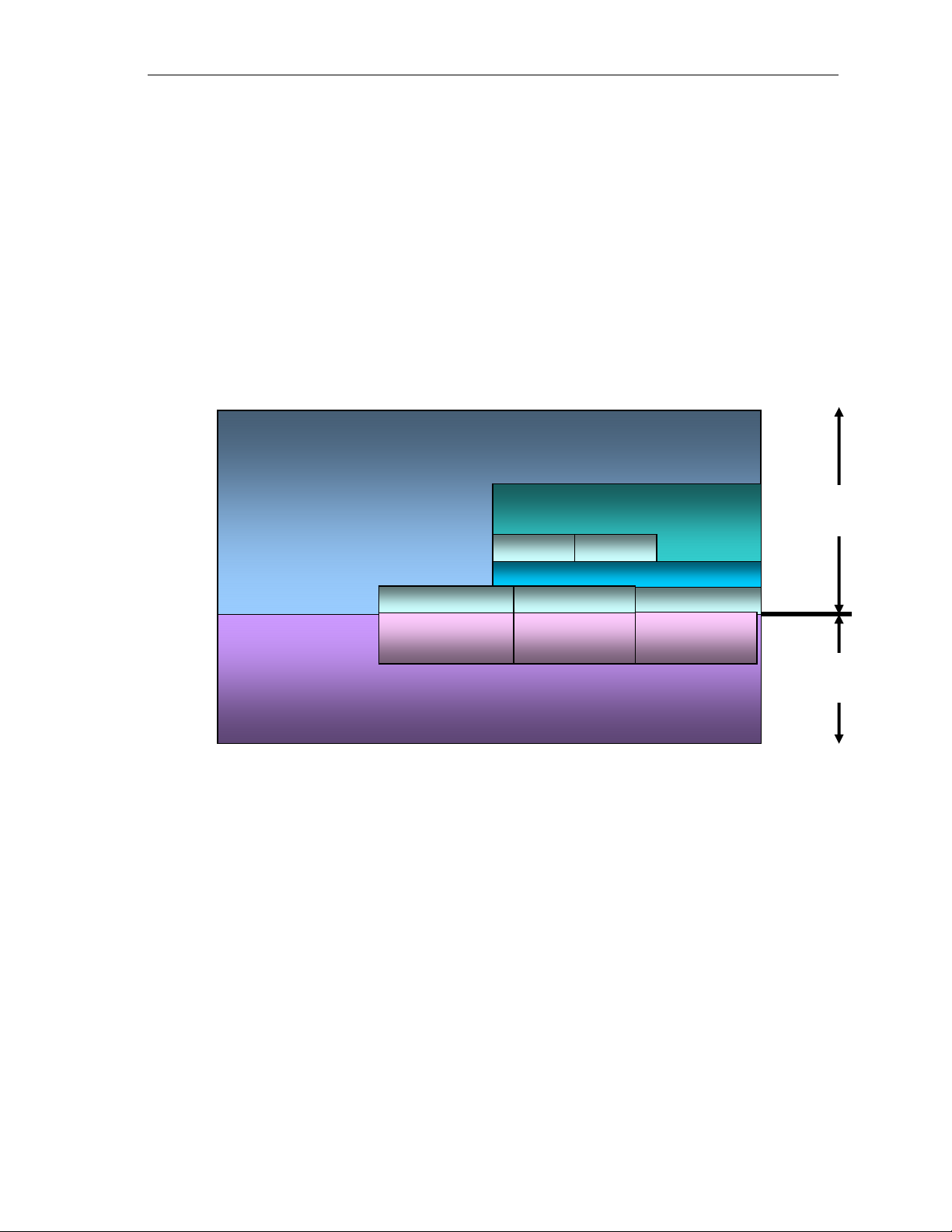
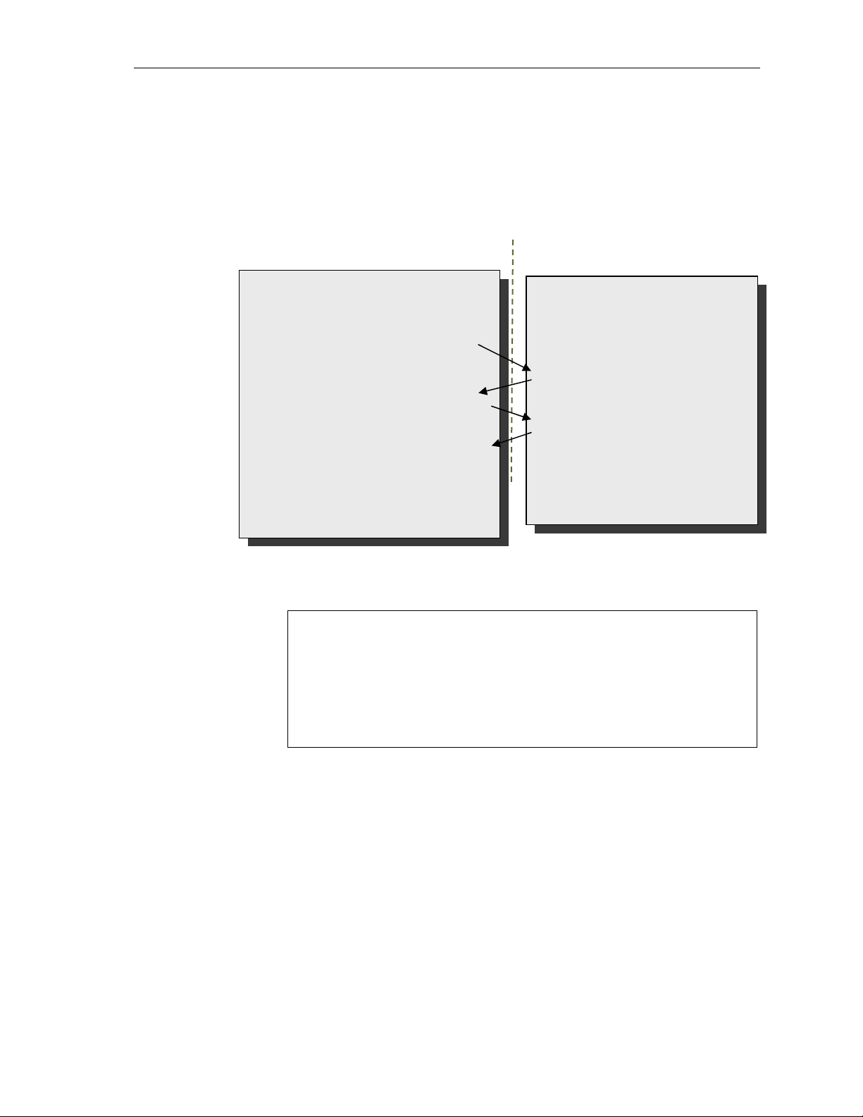
The following figure depicts the XDM interface to the client application.
process() call is made can be used by the application in
Client Application
XDM Interface
XDAIS Interface (IALG)
TI’s Codec Algorithms
As depicted in the figure, XDM is an extension to XDAIS and forms an
interface between the client application and the codec component. XDM
insulates the client application from component-level changes. Since TI’s
multimedia algorithms are XDM compliant, it provides you with the flexibility
to use any TI algorithm without changing the client application code. For
example, if you have developed a client application using an XDMcompliant MPEG4 video decoder, then you can easily replace MPEG4 with
another XDM-compliant video decoder, say H.263, with minimal changes
to the client application.
For more details, see eXpressDSP Digital Media (XDM) Standard API
Reference (literature number SPRUEC8).
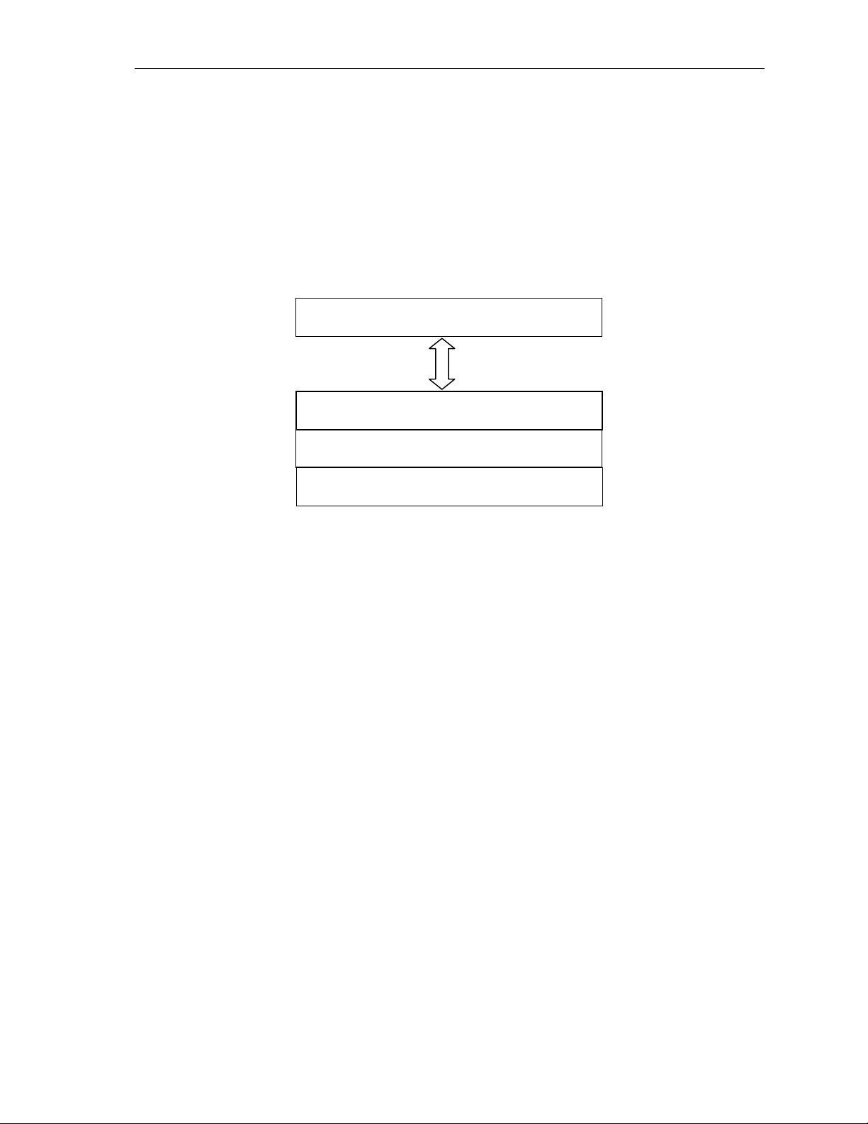
1.2.3 Framework Component
As discussed earlier, Framework Component acts like a middle layer
between the codec and OS and also serves as a resource manag er. The
following block diagram shows the FC components and their interfacing
structure.
1-4
Page 17
FC
Introduction
memutils
EDMA3
rman
hdvicpsync
ires
Figure 1-2. Framework Component Interfacing Structure.
Each component is explained in detail in the following sections.
1.2.3.1 IRES and RMAN
IRES is a generic, resource-agnostic, extendible resource query,
initialization and activation interface. The application framework defines,
implements and supports concrete resource interfaces in the form of IRES
extensions. Each algorithm implements the generic IRES interface, to
request one or more concrete IRES resources. IRES defines standard
interface functions that the framework uses to query, initialize,
activate/deactivate and reallocate concrete IRES resources. To create an
algorithm instance within an application framework, the algorithm and the
application framework agrees on the concrete IRES resource types that
are requested. The framework calls the IRES interface functions, in
addition to the IALG functions, to perform IRES resource initialization,
activation and deactivation.
FCtools
vicpsync
vicp
The IRES interface introduces support for a new standard protocol for
cooperative preemption, in addition to the IALG-style non-cooperative
sharing of scratch resources. Co-operative preemption allows activated
algorithms to yield to higher priority tasks sharing common scratch
resources. Framework components include the following modules and
interfaces to support algorithms requesting IRES-based resources:
IRES - Standard interface allowing the client application to query and
provide the algorithm with its requested IRES resources.
RMAN - Generic IRES-based resource manager, which manages and
grants concrete IRES resources to algorithms and applications. RMAN
uses a new standard interface, the IRESMAN, to support run-time
registration of concrete IRES resource managers.
Client applications call the algorithm’s IRES interface functions to query its
concrete IRES resource requirements. If the requested IRES resource type
matches a concrete IRES resource interface supported by the application
1-5
Page 18
Introduction
framework, and if the resource is available, the client grants the algorithm
logical IRES resource handles representing the allotted resources. Each
handle provides the algorithm with access to the resource as defin ed by the
concrete IRES resource interface.
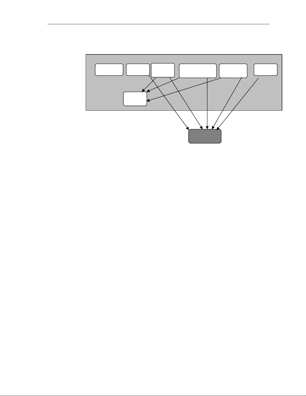
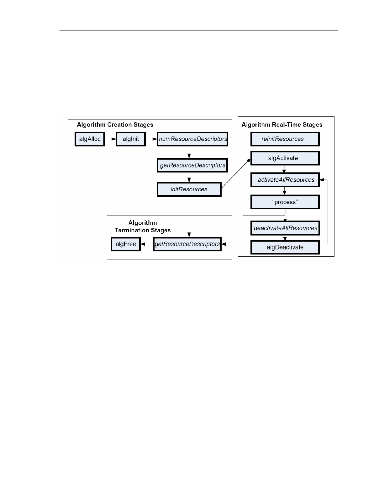
IRES interface definition and function-calling sequence is depicted in the
following figure. For more details, see Using IRES and RMAN Framework
Components for C64x+ (literature number SPRAAI5).
Figure 1-3. IRES Interface Definition and Function-calling Sequence.
In DM365/DM368, FC manages multiple resources for smooth intera ction with
other algorithms and application. The resources and the utilities p rovided by
FC are listed in this section.
1.2.3.2 HDVICP
The IRES HDVICP Resource Interface, IRES_HDVICP, allows algorithms
to request and receive handles representing Hardware Accelerator
resource, HDVICP, on supported hardware platforms. Algorithms can
request and acquire one of the co-processors using a single IRES request
descriptor. IRES_HDVICP is an example of a very simple resource type
definition, which operates at the granularity of the entire processor and
does not publish any details about the resource that is being acquired other
than the ‘id’ of the processor. It leaves it up to the algorithm to manage
internals of the resource based on the ID.
1.2.3.3 EDMA3
The IRES EDMA3 Resource Interface, IRES_EDMA3CHAN, allows
algorithms to request and receive handles representing EDMA3 resources
associated with a single EDMA3 channel. This is a very low-level resource
definition.
1-6
Page 19

1.2.3.4 VICP
VICP resource manager provides access to its VICP compute engine and
its buffer. The compute engines are MJCP, NSF, IMX0 and IMX1. In
addition to this, the VICP buffers are also assumed as resources and can
be requested as either named buffers (for MPEG and JPEG codec
operation) of generic scratch buffer (for H.264 codec operation).
1.2.3.5 HDVICP Sync
Synchronization is necessary in a coprocessor system. HDVICP sync
provides framework support for synchronization between codec and HDVICP
coprocessor usage. This module is used by frameworks or application s, which
have xDIAS algorithms that use HDVICP hardware accelarators.
Introduction
Note:
The existing xDAIS IDMA3 and IDMA2 interfaces can be used to request
logical DMA channels, but the IRES EDMA3CHAN interface provides
the ability to request resources with finer precision than with IDMA2 or
IDMA3.
1.2.3.6 Memutils
This is for generic APIs to perform cache and memory related operations.
cacheInv – Invalidates a range of cache
cacheWb – Writes back a range of cache
cacheWbInv – Writes back and invalidate cache
getPhysicalAddr – Obtains physical (hardware specific) address
1.2.3.7 TCM
ARM TCM resource manager provides access to request ARM926 TCM
memory. ARM926 in DM365/DM368 has 32K TCM, which can be allocated
to codec/algorithm on request. The allocation is in granularity of 1/2K
blocks, which can be used as scratch memory by the codec/algorithm.
1.3 Overview of H.264 Base/Main/High Profile Encoder
H.264 (from ITU-T, also called as H.264/AVC) is a popular video coding
algorithm enabling high quality multimedia services on a limited bandwidth
network. H.264 standard defines several profiles and levels that specify
restrictions on the bit stream and hence limits the capabilities needed to
decode the bit streams. Each profile specifies a subset of algorithmic
features and limits that all decoders conforming to that profile may support.
Each level specifies a set of limits on the values that may be used by the
syntax elements in the profile.
1-7
Page 20

Introduction
Some important H.264 profiles and their special features are (These are
feature as defined by H.264 standard, few of them may not be part of
DM365/DM368 H.264 implementation):
Baseline Profile:
o Only I and P type slices are present
o Only frame m ode (progressive) picture types are present
o Only CAVLC is supported
o ASO/FMO an d redundant slices for error concealment is supported
High Profile:
o Only I, P, and B type slices are present
o Frame and field picture modes (in progressive and interlaced modes)
picture types are present
o Both CAVLC and CABAC are supported
o ASO is not supported
o Tran sform 8x8 is supported
o Sequen ce scaling list is supported
o B frames and weighted prediction.
The input to the encoder is a YUV sequence, which can be of format 420
with the chroma components interleaved in little endian. The output of the
encoder is an H.264 encoded bit-stream in the byte-stream syntax. The
byte-stream consists of a sequence of byte-stream NAL unit syntax
structures. Each byte-stream NAL unit syntax structure contains one start
code prefix of size four bytes and value 0x00000001, followed by one NAL
unit syntax structure. The encoded frame data is a group of slices, each is
encapsulated in NAL units. The slice consists of the following:
Intra coded data: Spatial prediction mode and prediction error data,
subjected to DCT and later quantized.
Inter coded data: Motion information and residual error data
(differential data between two frames), subjected to DCT and later
quantized.
The first frame is called Instantaneous Decode Refresh (IDR) picture
frame. The decoder at the receiving end reconstructs the frame by spatial
intra-prediction specified by the mode and by adding the prediction error.
The subsequent frames may be intra or inter coded.
In case of inter coding, the decoder reconstructs the bit-stream by adding
the residual error data to the previously decoded image, at the location
specified by the motion information. This process is repeated until the
entire bit-stream is decoded.
1-8
In motion estimation, the encoder searches for the best match in the
available reference frame(s). After quantization, contents of some blocks
become zero. H.264 Encoder tracks this information and passes the
information of coded 4x4 blocks to inverse transform so that it can skip
computation for those blocks that contain all zero co-efficients and are not
coded.
Page 21
p
Input
cture
Pi
Introduction
H.264 Encoder defines in-loop filtering to avoid blocks across the 4x4 block
boundaries. It is the second most computational task of H.264 encoding
process after motion estimation. In-loop filtering is applied on all 4x4 edges
as a post-process and the operations depend upon the edge strength of
the particular edge.
H.264 Encoder applies entropy coding methods to use context based
adaptivity, which in turn improves the coding performance. All the macro
blocks, which belong to a slice, must be encoded in a raster scan order.
Baseline profile uses the Context Adaptive Variable Length Coding
(CAVLC). CAVLC is the stage where transformed and quantized
coefficients are entropy coded using context adaptive table switching
across different symbols. The syntax defined by the H.264 Encoder stores
the information at 4x4 block level.
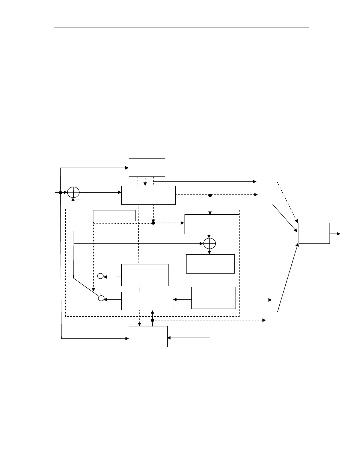
The following figure depicts the working of the encoder.
Coder
Control
Control
Transform /
Data
Quant
Transf coeffs
Intra-frame
Prediction
Motion-
ensation
Com
Motion-
Estimation
Figure 1-4. Block Diagram of H.264 Encoder.
From this point onwards, all references to H.264 Encoder mean H.264
Base/Main/High Profile Encoder only.
Scaling and Inv.
Transform
Deblocking
Filter
Reconstructed
Picture
Entropy
Coding
Output
Picture
Motion
Data
1-9
Page 22

Introduction
1.4 Supported Services and Features
This user guide accompanies TI’s implementation of H.264 Encoder on the
DM365/DM368 platform.
This version of the codec has the following supported features of the
standard:
eXpressDSP Digital Media (XDM1.0 IVIDENC1) interface compliant
Compliant with H.264 High Profile up to level 5.0
Supports resolutions up to 2048x2048
Supports YUV420 semi planer input format for the frames
Supports progressive and interlaced encoding
Generates bit-stream compliant with H.264 standard
Supports CAVLC and CABAC encoding
Supports sequence scaling matrix
Supports transform 8x8 and transform 4x4
Supports frame based encoding with frame size being multiples of 2
Supports rate control (CBR and VBR)
Supports Insertion of Buffering Period and Picture Timing
Supplemental Enhancement Information (SEI) and Video Usability
Information (VUI)
Supports Unrestricted Motion Vectors (UMV)
Supports Half Pel and Quarter Pel Interpolation for motion estimation
Supports following Smart Codec features:
o Simple Two Pass (STP) Encoding
o Regi on of Interest (ROI)
Supports Low latency feature
o Can b e configured to provide output at NAL granularity or after entire
frame is encoded.
o Suppo rts encoded output in NAL stream or Bytes stream format
DM365/DM368 H.264 encoder can be configured in two modes:
Platinum mode, which gives 1080P@30fps performance in DM368 –
432 Mhz device
1-10
Version 1.1 backward compatible mode which gives performance of
720P@30fps on DM365/DM368 - 300 MHz
This version of the encoder does not support the following features as per
the Baseline Profile feature set:
Error Resilience features such as ASO/FMO and redundant slices
Page 23

Introduction
Adaptive Reference Picture Marking
Reference Picture List Reordering
1.5 Comparison between version 01.10.00.xx wi th new version 02.00.00.xx (Platinum Encoder)
Version 02.00.00.xx is a new enhanced codec version with 1.5x better
performance than earlier version without affecting quality. Few of the
enhancements are listed below:
Achieves 1080P@30fps on DM368.
More feature rich codecs which includes
• Smart codec technology
• Low latency API support
Version 02.00.00.xx also supports version 1.1 standard mode as a
backward compatible option. This can be enabled by setting
encodingPreset = XDM_USER_DEFINED and encQuality = 0. It
enables application that needs low-resolution encoding, lesser EDMA
channels or some specific tools like perceptual rate control.
Feature Version 1.1 - Gen 1 Versio n 2.0 - Platinum
Resolution Min – 128 x 96
Max – 2k x 2k
Performance 720P@30fps on DM365/DM368 1080P@30fps on DM368
EDMA channels 37 46
Support for Ver
1.1 – Gen1
NA YES
Min – 320 x 128
Max – Current (2k x 2k)
1-11
Page 24

Introduction
This page is intentionally left blank
1-12
Page 25

Chapter 2
Installation Overview
This chapter provides a brief description on the system requirements and
instructions for installing the codec component. It also provides information on
building and running the sample test application.
Topic Page
2.1 System Requirements for Linux 2-2
2.2 Installing the Component for Linux 2-2
2.3 Building and Running the Sample Test Application on Linux 2-4
2.4 Configuration Files 2-4
2.5 Standards Conformance and User-Defined Inputs 2-8
2.6 Uninstalling the Component 2-9
2-1
Page 26

Installation Overview
2.1 System Requirements for Linux
This section describes the hardware and software requirement s for the
normal functioning of the codec in MV Linux OS. For details about the
version of the tools and software, see Release Note
2.1.1 Hardware
DM365/DM368 EVM (Set the bits 2 and 3 of switch SW4 to low(0)
position and Set the bits 4 and 5 of switch SW5 to high(1) position)
RS232 cable and network cable
2.1.2 Software
The following are the software requirements for the normal functioning of
the codec:
Build Environment: This project is built using Linux with MVL ARM
tool chain.
ARM Tool Chain: This project is compiled and linked using MVL ARM
tool chain.
2.2 Installing the Component for Linux
The codec component is released as a compressed archive. To install the
codec, extract the contents of the tar file onto your local hard disk. The tar
file extraction creates a directory called
dm365_h264enc_xx_xx_xx_xx_production.
directories created in this directory.
Note:
xx_xx_xx_xx in the directory name is the version of the codec. For
example, If the version of the codec is 02.00.01.00, then the directory
created on extraction of tar file is
dm365_h264enc_02_00_01_00_production.
Figure 2-5 shows the sub-
2-2
Page 27
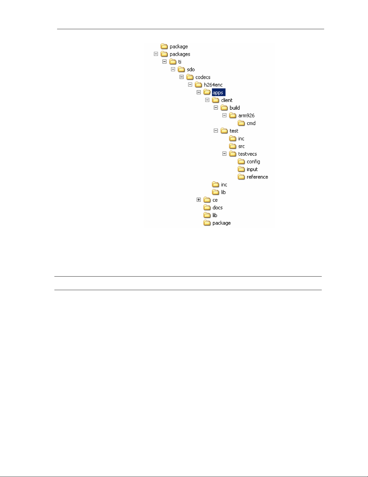
Installation Overview
Figure 2-5. Component Directory Structure for Linux.
Table 2-2 provides a description of the sub-directories created in the
dm365_h264enc_xx_xx_xx_xx_production directory.
Table 2-2. Component Directories for Linux.
Sub-Directory Description
\package Contains files related while building the package
\packages\ti\sdo\codecs\h264enc\lib Contains the codec library files on host
\packages\ti\sdo\codecs\h264enc\docs Contains user guide, datasheet, and release notes
\packages\ti\sdo\codecs\h264enc\apps\clie
nt\build\arm926
\packages\ti\sdo\codecs\h264enc\apps\clie
nt\build\arm926\cmd
\packages\ti\sdo\codecs\h264enc\apps\clie
nt\build\arm926\map
\packages\ti\sdo\codecs\h264enc\apps\clie
nt\test\src
Contains the makefile to built sample test application
Contains a template (.xdt) file to used to generate linker
command file
Contains the memory map generated on compilation of the
code
Contains application C files
\packages\ti\sdo\codecs\h264enc\apps\clie
nt\test\inc
Contains header files needed for the application code
2-3
Page 28

Installation Overview
Sub-Directory Description
\packages\ti\sdo\codecs\h264enc\apps\clie
nt\test\testvecs\input
\packages\ti\sdo\codecs\h264enc\apps\clie
nt\test\testvecs\output
\packages\ti\sdo\codecs\h264enc\apps\clie
nt\test\testvecs\reference
\packages\ti\sdo\codecs\h264enc\apps\clie
nt\test\testvecs\config
Contains input test vectors
Contains output generated by the codec
Contains read-only reference output to be used for verifying
against codec output
Contains configuration parameter files
2.3 Building and Running the Sample Test Application on Linux
To build the sample test application in linux environment, follow these
steps
1) Verify that dma library h264v_ti_dma_dm365.a exists in the
packages\ti\sdo\codecs\h264enc\lib.
2) Verify that codec object library library h264venc_ti_arm926.a exists in
the \packages\ti\sdo\codecs\h264enc\lib.
3) Ensure that you have installed the LSP, Montavista arm tool chain,
XDC, Framework Components releases with version numbers that are
mentioned in the release notes.
4) In the folder \packages\ti\sdo\codecs\h264enc\client\build\arm926,
change the paths in the file rules.make according to your setup.
5) Open the command prompt at the sub-directory
\packages\ti\sdo\codecs\h264enc\client\build\arm926 and type the
command make. This generates an executable file h264venc-r in the
same directory.
To run the executable generated from the above steps:
1) Load the kernel modules by typing the command ./loadmodules.sh,
which initializes the CMEM pools.
2) Now branch to the directory where the executable is present and type
./h264venc-r in the command window to run.
2.4 Configuration Files
This codec is shipped along with:
Generic configuration file ( testvecs.cfg) – list of configuration files for
running the codec on sample test application.
Encoder configuration file ( testparams.cfg) – specifies the
configuration parameters used by the test application to configure the
Encoder.
2-4
Page 29

2.4.1 Generic Configuration File
The sample test application shipped along with the codec uses the
configuration file, Testvecs.cfg for determining the input and reference files
for running the codec and checking for compliance. The testvecs.cfg file is
available in the
\packages\ti\sdo\codecs\h264enc\apps\client\test\testvecs\config subdirectory.
The format of the testvecs.cfg file is:
X
config
input
output/reference
recon
where:
X may be set as:
o 1 - for co mpliance checking, no output file is created
o 0 - for writing the output to the output file
Installation Overview
config is the Encoder configuration file. For details, see Section 2.4.2.
input is the input file name (use complete path).
output/reference is the output file name (if X is 0) or reference file
name (if
recon is reconstructed YUV output file name (use complete path).
X is 1) (use complete path).
2-5
Page 30

Installation Overview
A sample testvecs.cfg file is as shown:
For output dump mode:
0
..\..\..\test\testvecs\config\testparams.cfg
..\..\..\test\testvecs\input\input.yuv
..\..\..\test\testvecs\output\output.264
..\..\..\test\testvecs\output\recon.yuv
For reference bit-stream compliance test mode:
1
..\..\..\test\testvecs\config\testparams.cfg
..\..\..\test\testvecs\input\input.yuv
..\..\..\test\testvecs\reference\reference.264
..\..\..\test\testvecs\output\recon.yuv
2.4.2 Encoder Configuration File
The encoder configuration file, testparams.cfg contains the configuration
parameters required for the encoder. The testparams.cfg file is available in
the \client\test\testvecs\config sub-directory.
A sample Testparams.cfg file is as shown:
# Config File Format is as follows
# <ParameterName> = <ParameterValue> # Comment
####################################################
Parameters
####################################################
ImageWidth = 1280 # Image width in Pels, must be multiple of 16
ImageHeight = 720 # Image height in Pels, must be multiple of 16
FrameRate = 30000 # Frame Rate per second*1000(1-120)
BitRate = 4000000 # Bitrate(bps) #if ZERO=>> RC is OFF
ChromaFormat = 9 # 9 => XDM_YUV_420P
InterlacedVideo = 0 # 0: Progressive, 1 :Interlaced
TimerScale = 60. # Timer Resolution for Picture Timing
NumUnitsInTicks = 1 # Number of Timer units per Tick
AspectRatioWidth = 1 # Aspect Ratio Width Scale
AspectRatioHeight = 1 # Aspect Ratio Height Scale
PixelRange = 1 # 1 =>Y- 0 to 255, Cb/Cr-0 to 255
0 => Y-16 to 235, Cb/Cr-16 to 240
EnableVUIParam = 1 # 1 => Enable VUI parameters,
0 => Disable VUI Parameters
EnableBufSEI = 1 # 1 => Enable Buffering Period SEI Message,
0 => Disable
ME_Type = 0 # ME search algorithm
0 => Normal,
1 => Low Power
RC_PRESET = 5 # 1 => Low Delay,
2 => Storage,
3 => 2 Pass,
4 => None,
5 => user defined
ENC_PRESET = 3 # 3 => User Defined Parameters
####################################################
# Encoder Control
####################################################
ProfileIDC = 100 # Profile IDC (66=baseline, 77=main,
100=high profile)
2-6
Page 31

Installation Overview
LevelIDC = 30 # Level IDC (e.g. 20 = level 2.0)
IntraPeriod = 30 # Period of I-Frames
IDRFramePeriod = 0 # Period of IDR Frames
FramesToEncode = 10 # Number of frames to be coded
SliceSize = 0 # Size of each slice
EnMeMultiPart = 0 # 1 => Enable MB Partitions,
0=> Single MV for each MB
RateControl = 1 # 0 => CBR,
1 => VBR,
2 = Fixed QP
MaxDelay = 2000 # Delay Parameter for Rate Control in
Milliseconds
QPInit = 28 # Initial QP for RC (-1,0-51)
QPISlice = 48 # Quant. param for I Slices (0-51)
QPSlice = 48 # Quant. param for non - I slices (0-51)
MaxQP = 42 # Maximum value for QP (0-51)
MinQP = 0 # Minimum value for QP (0-51)
MaxQPI = 40 # Maximum value for QP for I frame(0-51)
MinQPI = 0 # Minimum value for QP for I Frame(0-51)
IntraThrQF = 0 # Reserved
AirRate = 0 # Number of Forced Intra MBs
UnRestrictedMV = 0 #1: Enable 0:Disable
EntropyCodingMode = 1 # Entropy Coding Mode (0 = CAVLC, 1 = CABAC)
Transform8x8FlagIntra = 1 # 0 = Disable,
# 1 = Enable
Transform8x8FlagInter = 1 # 0 = Disable,
# 1 = Enable
SequenceScalingFlag = 0 # 0 = Disable,
# 1 = Auto,
# 2 = Low,
# 3 = Moderate,
# 4 = Reserved
PerceptualRC = 1 # 1 => Enable Perceptual QP modulation,
# 0 => Disable
EncoderQuality = 1 # 0 => Ver 1.1 mode (Backward compatible),
# 2 => Platinum mode
mvSADout = 0 # 0=>disable mvsad out,
# 1=>enable mvsad out
useARM926Tcm = 1 # 0->do not use arm 926 tcm,
# 1-> use arm 926 tcm
enableROI = 0 # 0->disable ROI
# 1-> enable ROI
mapIMCOPtoDDR = 0 #0->do not use DDR
# 1-> use DDR instead of IMCOP
metaDataGenerateConsume = 0 # 0->Not in use,
# 1-> Generate Meta data,
# 2-> Use Metadata generated by other encoder.
sliceMode = 0 # 0 -> no multiple slices,
# 1 -> Reserved,
# 2 -> multiple slices-MBs/slice,
# 3 -> multiple slices - Rows/slice
outputDataMode = 1 # 0 -> low latency, encoded streams produced
# after N (configurable) slices encode,
# 1 -> encoded stream produce at the end of frame
sliceFormat = 1 # 0-> encoded stream in NAL unit format,
#1 -> encoded stream in bytes stream format
####################################################
Loop filter parameters
####################################################
LoopFilterDisable = 0 # Disable loop filter in slice header
0=Filter,
2-7
Page 32

Installation Overview
1=No Filter,
2 = Disable across Slice Boundaries
To check the functionality of the codec for the inputs other than those
provided with the release, change the configuration file accordingly, and
follow the steps as described in Section
2.4.3 Encoder Sample Base Param Setting
The encoder can be run in IVIDENC1 base class setting. The extended
parameter variables of encoder will then assume default values. The
following list provides the typical values of
typedef struct IVIDENC1_Params {
XDAS_Int32 size;
XDAS_Int32 encodingPreset = XDM_HIGH_SPEED; // Value = 2
XDAS_Int32 rateControlPreset = IVIDEO_STORAGE; //value = 2
XDAS_Int32 maxHeight = 720;
XDAS_Int32 maxWidth = 1280;
XDAS_Int32 maxFrameRate = 120000;
XDAS_Int32 maxBitRate = 50000000;
XDAS_Int32 dataEndianness = XDM_BYTE;
XDAS_Int32 maxInterFrameInterval = 1;
XDAS_Int32 inputChromaFormat = XDM_YUV_420SP; //value = 9
XDAS_Int32 inputContentType = IVIDEO_PROGRESSIVE;
XDAS_Int32 reconChromaFormat XDM_YUV_420SP; //value = 9;
} IVIDENC1_Params;
typedef struct IVIDENC1_DynamicParams {
XDAS_Int32 size; /**< @sizeField */
XDAS_Int32 inputHeight; /**< Input frame height. */
XDAS_Int32 inputWidth; /**< Input frame width. */
XDAS_Int32 refFrameRate = 30000;
XDAS_Int32 targetFrameRate = 30000;
XDAS_Int32 targetBitRate; < 10000000 /**< Target bit rate
in bits per second. */
XDAS_Int32 intraFrameInterval = 29;
XDAS_Int32 generateHeader = 0;
XDAS_Int32 captureWidth; // for demo, same as inputWith
XDAS_Int32 forceFrame; = IVIDEO_NA_FRAME
XDAS_Int32 interFrameInterval = 0;
XDAS_Int32 mbDataFlag = 0;
} IVIDENC1_DynamicParams;
typedef struct IVIDENC1_InArgs {
XDAS_Int32 size; /**< @sizeField */
XDAS_Int32 inputID; /* as per application*/
XDAS_Int32 topFieldFirstFlag = 0;
} IVIDENC1_InArgs;
2.2.
IVIDENC1 base class variables.
2.5 Standards Conformance and User-Defined Inputs
To check the reference bit-stream co nformance of the codec for the default
input file shipped along with the codec, follow the steps as described in
Section
To check the conformance of the codec for other input files of your choice,
follow these steps:
1) Copy the input files to the \client\test\testvecs\input sub-directory.
2-8
2.3.
Page 33

2) Copy the reference files to the \client\test\testvecs\reference subdirectory.
3) Edit the configuration file, Testvecs.cfg available in the
\client\test\testvecs\config sub-directory. For details on the format of
the testvecs.cfg file, see section
For each encoded frame, the application displays the message
indicating the frame number. In reference bit-stream compliance check
mode, the application additionally displays FAIL message, if the bitstream does not match with reference bit-stream.
After the encoding is complete, the application displays a summary of
total number of frames encoded. In reference bit-stream compliance
check mode, the application additionally displays PASS message, if
the bit-stream matches with the reference bit-stream.
If you have chosen the option to write to an output file (X is 0), you can
use any of the standard file comparison utility to compare the codec
output with the reference output and check for conformance.
2.6 Uninstalling the Component
Installation Overview
2.4.
To uninstall the component, delete the codec directory from your hard disk.
2-9
Page 34

Installation Overview
This page is intentionally left blank
2-10
Page 35

Chapter 3
Sample Usage
This chapter provides a detailed description of the sample test application
that accompanies this codec component.
Topic Page
3.1 Overview of the Test Application 3-2
3.2 Handshaking Between Application and Algorithm 3-6
3.3 Cache Management by Application 3-9
3.4 Sample Test Application 3-11
3-1
Page 36

Sample Usage
3.1 Overview of the Test Application
The test application exercises the IVIDENC1 base class of the H.264
Encoder library. The main test application files are h264encoderapp.c and
h264encoderapp.h. These files are available in the \client\test\src and
\client\test\inc sub-directories respectively.
Figure 3-1 depicts the sequence of APIs exercised in the sample test
application.
Figure 3-1. Test Application Sample Implementation
3-2
Page 37

The test application is divided into four logical blocks:
Parameter setup
Algorithm instance creation and initialization
Process call
Algorithm instance deletion
3.1.1 Parameter Setup
Each codec component requires various codec configuration pa rameters to
be set at initialization. For example, a video codec requires parameters
such as video height, video width, and so on. The test application obtains
the required parameters from the Encoder configuration files.
In this logical block, the test application does the following:
1) Opens the generic configuration file, testvecs.cfg and reads the list of
Encoder configuration file name (testparams.cfg).
Sample Usage
2) Opens the Encoder configuration file, (testparams.cfg) and reads the
various configuration parameters required for the algorithm.
For more details on the configuration files, see Section
3) Sets the
IVIDENC1_Params structure based on the values it reads
from the Testparams.cfg file.
4) Sets the extended parameters of the
based on the values it reads from the testparams.cfg file.
After successful completion of the above steps, the test application does
the algorithm instance creation and initialization.
3.1.2 Algorithm Instance Creation and Initialization
In this logical block, the test application accepts the various initialization
parameters and returns an algorithm instance pointer. The following APIs
are called in a sequence:
algNumAlloc() - To query the algorithm about the number of
1)
memory records it requires.
algAlloc() - To query the algorithm about the memory requirement
2)
to be filled in the memory records.
algInit() - To initialize the algorithm with the memory structures
3)
provided by the application.
2.4.
IH264VENC_Params structure
A sample implementation of the create function that calls
algNumAlloc(), algAlloc(), and algInit() in sequence is provided
ALG_create() function implemented in the alg_create.c file.
in the
After successful creation of the algorithm instance, the test application
does DMA resource allocation for the algorithm.
3-3
Page 38
Sample Usage
3.1.3 Process Call
Note:
DMAN3 function and IDMA3 interface is not implemented in
DM365/DM368 codecs. Instead, it uses a DMA resource head er file,
which gives the framework the flexibility to change DMA resource to
codec.
After algorithm instance creation and initialization, the test application does
the following:
1) Sets the dynamic parameters (if they change during run-time) by
calling the
2) Sets the input and output buffer descriptors required for the
process()function call. The input and output buffer descriptors are
obtained by calling the
command.
control() function with the XDM_SETPARAMS command.
control() function with the XDM_GETBUFINFO
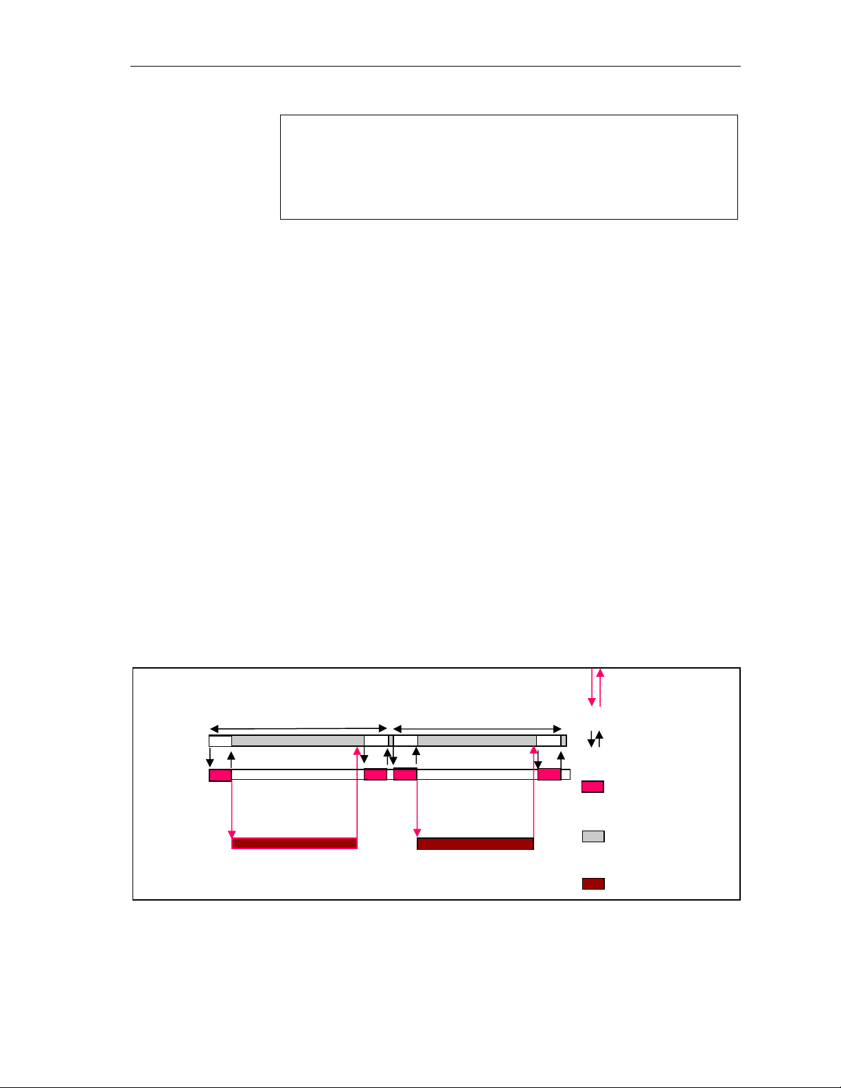
Host
System
application
HDVICP
Tasks
3) Implements the process call based on the mode of operation –
blocking or non-blocking. These different modes of operation are
explained below. The behavior of the algorithm can be controlled using
various dynamic parameters (see section
process()functions are input and output buffer descriptors, pointer to
IVIDENC1_InArgs and IVIDENC1_OutArgs structures.
the
4) Call the
After triggering the start of the encode/decode frame start, the video
task can be moved to SEM-pend state using semaphores. On receipt
of interrupt signal for the end of frame encode/decode, the application
should release the semaphore and resume the video task, which
performs book-keeping operations and updates the output parameters
structure -
Process call frame n
MB level tasks for
frame n
4.2.1.10). The inputs to the
process() function to encode/decode a single frame of data.
IVIDENC1_OutArgs.
Interrupt between
HDVICP and Host
Process call frame n+1
Transfer of
tasks at Host
Host Video
Task
Host system
MB level tasks for
frame n+1
tasks
HDVICP Busy
Figure 3-2. Process Call with Host Release
3-4
Page 39

Sample Usage
Note:
The process call returns control to the application after the initial
setup related tasks are completed.
Application can schedule a different task to use the Host resource
released free.
All service requests from HDVICP are handled through interrupts.
Application resumes the suspended process call after handling the
last service request for HDVICP.
Application can now complete concluding portions of the process
call.
The control() and process() functions should be called only within
the scope of the
functions. The
algActivate() and algDeactivate() XDAIS
algActivate() and algDeactivate() XDAIS functions
activate and deactivate the algorithm instance respectively. Once the
algorithm is activated, the
control() and process() functions can be of
any order. The following APIs are called in a sequence:
control() (optional) - To query the algorithm on status or setting of
1)
dynamic parameters and so on, using the seven available control
commands.
process() - To call the Encoder with appropriate input/output buffer
2)
and arguments information.
control() (optional) - To query the algorithm on status or setting of
3)
dynamic parameters and so on, using the seven available control
commands.
algDeactivate() - To deactivate the algorithm instance.
4)
The for loop encapsulates frame level
input buffer and the output buffer pointer every time before the next call.
The for loop runs for the designated number of frames and breaks-off
whenever an error condition occurs.
In the sample test application, after calling
data is either dumped to a file or compared with a reference file.
3.1.4 Algorithm Instance Deletion
Once decoding/encoding is complete, the test application deletes the
current algorithm instance The following APIs are called in a sequence:
algNumAlloc() - To query the algorithm about the number of
1)
memory records it used.
process() call and updates the
algDeactivate(), the output
algFree() - To query the algorithm to get the memory record
2)
information, which can be used by the application for freeing them up.
A sample implementation of the delete function that calls
algFree() in sequence is provided in the aLG_delete() function
and
algNumAlloc()
implemented in the alg_create.c file.
3-5
Page 40
Sample Usage
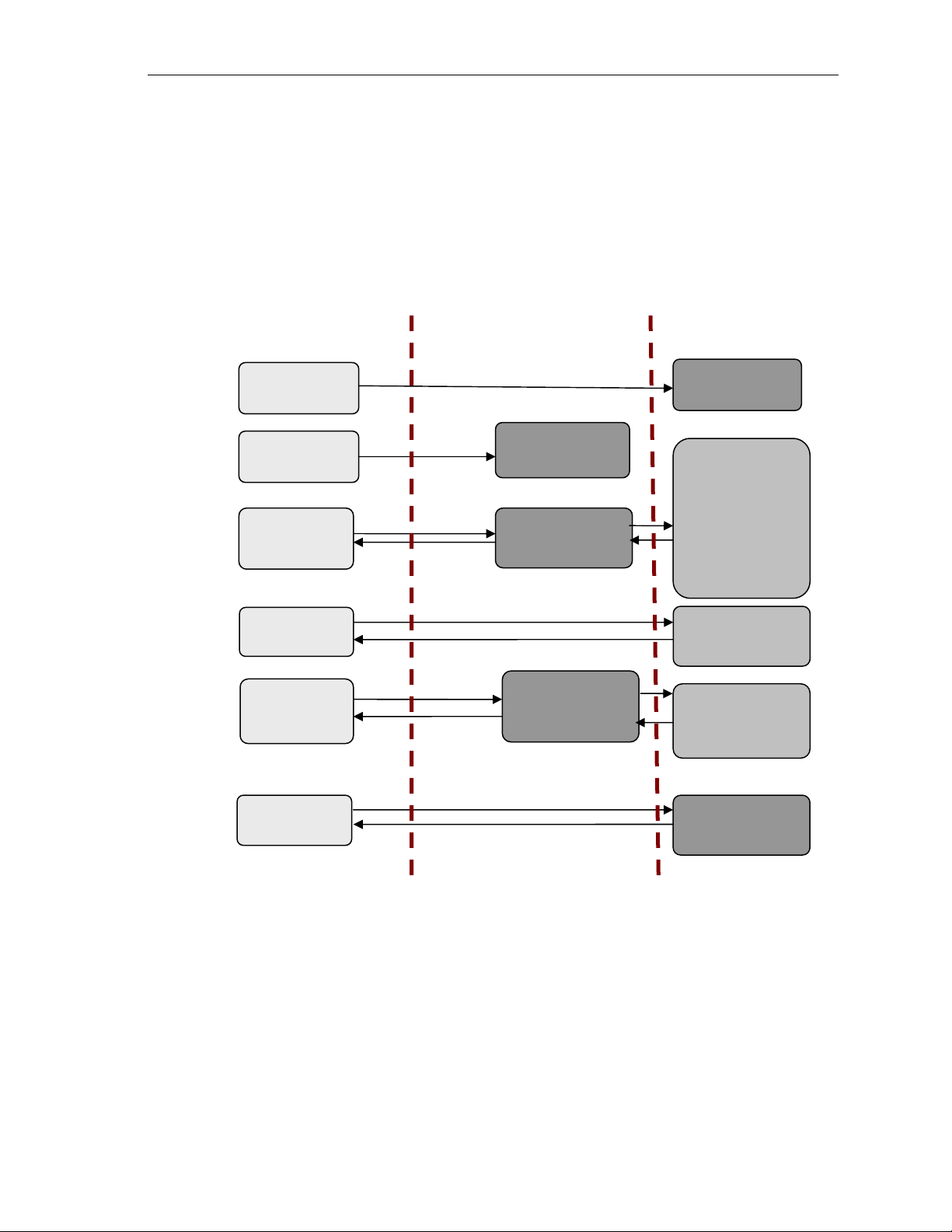
3.2 Handshaking Between Application and Algorithm
3.2.1 Resource Level Interaction
Following diagram explains the resource level interaction of the application
with framework component and codecs. Application uses XDM for
interacting with codecs. Similarly, it uses RMAN to grant resources to the
codec.
Application
Framework component
CODEC
Creation
IALG_create fns
Register
Resource
Assign
Resource
RMAN_register
RMAN_assign
resource
VICP buffers
memories, DMA
channel
information and
details of
iresfxns
implemented by
the codec.
Control and
Process
Encoding /
Decoding
Free
Resource and
Exit
RMAN_freeresou
rce and
RMAN_exit
Details of
resource held by
codec
Codec
Deletion
Figure
3-3. Resource Level Interaction.
3-6
IALG_free fns
Page 41
_
3.2.2 Handshaking Between Application and Algorithms
Application provides the algorithm with its implementation of functions for
the video task to move to SEM-pend state, when the execution happens in
the co-processor. The algorithm calls these application functions to move
the video task to SEM-pend state.
Sample Usage
Codec
Application Side
process()
#include <…/ires_hdvicp.h>
void _MyCodecISRFunction();
MYCODEC::IVIDENC1::process() {
:
…. set up for frame encoder
HDVICPSYNC_start(handle,
HDVICPSYNC_FIQ,
handle->hdvicpResourceHandles[0])
HDVICPSYNC_wait(((H264VENC_TI_Obj
*)handle)->hdvicpResourceHandles[0]);
/* Wait until HDVICP set interrupt */
// Release of HOST
…. End of frame processing
}
void H264VENC_TI_isrfunction
(IALG_Handle handle)
{ H264venc_TII_Obj *h264venc = (void
*)handle;
Figure 3-4. Interaction Between Application and Codec.
Note:
Process call architecture shares Host resource among multiple
threads.
Framework Provided
HDVICP Callback APIs
int _doneSemaphore;
HDVICP_configure(handle,
hdVicpHandle, ISRFunction){
installNonBiosISR(handle,
hdvicpHandle, ISRFunction);
}
VICP_register();
VICP_done();
VICP_unregister();
ISR ownership is with the FC resource manager – outside the
codec.
Codec implementation is OS independent.
The functions to be implemented by the application are:
1) HDVICPSYNC_start(IALG_Handle handle,
HDVICPSYNC_InterruptType intType, IRES_HDVICP_Handle
hdvicpHandle)
This function is called by the algorithm to register the interrupt with the
OS. This function also configures the Framework Component interrupt
synchronization routine.
2) HDVICPSYNC_wait (IRES_HDVICP_Handle hdvicpHandle)
This function is a FC call back function use to pend on a semaphore.
Whenever the codec has completed the work on Host processor (after
transfer of frame level encode/decode to HDVICP) and needs to relive
the CPU for other tasks, it calls this function.
3-7
Page 42

Sample Usage
Framework calls Encoder Init
Framework Calls Encode frame
process
This function of FC implements a semaphore which goes into pend
state and then the OS switches the task to another non-codec task.
Interrupts from HDVICP to Host ARM926 is used to inform when the
frame processing is done. HDVICP sends interrupt which maps to
No 10 (KALINT9 Video MJCP)
of ARM926 INTC. After receiving this
interrupt, the semaphore on which the codec task was waiting gets
released and the execution resumes after the
HDVICPSYNC_wait()
function.
The following figure explains the interrupt interaction between
application and codec.
HOST ARM926 HDVICP
This interrupt is not
visible to
framework. It
happens inside
codec library
INT
Codec lib calls HDVICPSYNC_start
to register the ISR with framework
Codec library internally sends
interrupt to HDVICP to start
processing
Codec calls framework
HDVICP_wait()
HDVICPSYNC_wait() uses to make
the codec task sleep
Different task running
Pending over
Exit HDVICPSYNC_wait()
Codec task wakes up to finish end
of frame processing and returns
back to framework
Start frame processing
At the end send interrupt to Host
that it has finished
Inform Host through interrupt
This interrupt
should be serviced
by framework
Figure 3-5. Interrupt Between Codec and Application.
3-8
Page 43

3.3 Cache Management by Application
3.3.1 Cache Usage By Codec Algorithm
The codec source code and data, which runs on Host ARM926 can be
placed in DDR. The host of DM365/DM368 has MMU and cache that the
application can enable for better performance. Since the codec also uses
DMA, there can be inherent cache coherency problems when application
turns on the cache.
3.3.2 Cache and Memory Related Call Back Functions for Linux
To resolve the cache coherency and virtual to physical addre ss issues, FC
provides memory until library. These following functions can be used by
codecs to resolve the cache coherency issues in Linux:
cacheInvalidate
cacheWb
Sample Usage
cacheWbInv
getPhysicalAddr
3-9
Page 44

Sample Usage
3.3.2.1 cacheInvalidate
In cache invalidation process, the entries of the cache are deleted. This
API invalidates a range of cache.
Void MEMUTILS_cacheInv (Ptr addr, Int sizeInBytes)
3.3.2.2 cacheWb
This API writes back cache to the cache source when it is necessary.
Void MEMUTILS_cacheWb (Ptr addr, Int sizeInBytes)
3.3.2.3 cacheWbInv
This API writes back cache to the cache source when it is necessary and
deletes the cache contents.
Void MEMUTILS_cacheWbInv (Ptr addr, Int sizeInBytes)
3.3.2.4 getPhysicalAddr
This API obtains the physical address.
Void* MEMUTILS_getPhysicalAddr (Ptr addr))
3-10
Page 45

3.4 Sample Test Application
The test application exercises the IVIDENC1 base class of the H.264
Encoder.
Table 3-1. process () Implementation
/* Main Function acting as a client for Video encode Call*/
/* Acquiring and intializing the resources needed to run the
encoder */
iresStatus = (IRES_Status) RMAN_init();
iresStatus = (IRES_Status) RMAN_register(&IRESMAN_EDMA3CHAN,
(IRESMAN_Params *)&configParams);
/*---------------- Encoder creation -----------------*/
handle = H264VENC_create(&fxns, ¶ms)
/*Getting instance of algorithms that implements IALG and
IRES functions*/
iErrorFlag = RMAN_assignResources((IALG_Handle)handle,
&H264VENC_TI_IRES, /* IRES_Fxns* */
1 /* scratchId */);
/* Get Buffer information */
iErrorFlag = H264VENC_control(
handle, // Instance Handle
XDM_GETSTATUS, // Command
&dynamicparams, // Pointer to Dynamicparam structure
&status // Pointer to the status structure
);
/*SET BASIC INPUT PARAMETERS */
iErrorFlag = H264VENC_control(
handle, // Instance Handle
XDM_GETSTATUS, // Command
&dynamicparams, // Pointer to Dynamicparam structure
&status // Pointer to the status structure
);
/* Based on the Num of buffers requested by the algorithm,
the application will allocate for the same here
*/
AllocateH264IOBuffers(
status, // status structure
&inobj, // Pointer to Input Buffer Descriptor
&outobj) // Pointer to Output Buffer Descriptor
);
/*Set Dynamic input parameters */
iErrorFlag = H264VENC_control(
handle, // Instance Handle
XDM_GETSTATUS, // Command
&dynamicparams, // Pointer to Dynamicparam structure
&status // Pointer to the status structure
);
/* for Loop for encode Call for a given no of frames */
For(;;)
/* Read the input frame in the Application Input Buffer */
ReadInputData (inFile);
/*----------------------------------------------------*/
/* Start the process : To start Encoding a frame */
/* This will always follow a H264VENC_encode_end call */
Sample Usage
3-11
Page 46

Sample Usage
/*----------------------------------------------------*/
iErrorFlag = H264VENC_encode (
handle, // Instance Handle - Input
&inobj, // Input Buffers - Input
&outobj, // Output Buffers - Output
&inargs, // Input Parameters - Input
&outargs // Output Parameters - Output
);
/* Get the statatus of the Encoder using control */
H264VENC_control(
handle, // Instance Handle
XDM_GETSTATUS, // Command - GET STATUS
&dynamicparams, // Input
&status // Output
);
}
/* end of Do-While loop - which Encodes frames */
/* Free Input and output buffers */
FreeH264IOBuffers(
&inobj, // Pointer to Input Buffer Descriptor
&outobj // Pointer to Output Buffer Descriptor );
/* Free assigned resources */
RMAN_freeResources((IALG_Handle)(handle),
&H264VENC_TI_IRES, /* IRES_Fxns* */
);
/* Delete the encoder Object handle*/
H264VENC_delete(handle);
/* Unregister protocal*/
RMAN_unregister(&IRESMAN_EDMA3CHAN);
RMAN_exit();
Note:
This sample test application does not depict the actual function parameter or
control code. It shows the basic flow of the code.
3-12
Page 47

Chapter 4
API Reference
This chapter provides a detailed description of the data structures and
interfaces functions used in the codec component.
Topic Page
4.1 Symbolic Constants and Enumerated Data Types 4-2
4.2 Data Structures 4-22
4.3 H.264 Encoder ROI specific Data Structures and Enumerations 4-50
4.4 H264 Encoder Two Pass Encoder data structure 4-53
4.5 H.264 Encoder Low latency specific Data Structures and
Enumerations
4.6 Interface Functions 4-59
4-55
4-1
Page 48

API Reference
4.1 Symbolic Constants and Enumerated Data Types
This section summarizes all the symbolic constants specified as either
#define macros and/or enumerated C data types. For each symbolic
constant, the semantics or interpretation of the same is also provided.
4.1.1 Common XDM Symbolic Constants and Enumerated Data Types
Table 4-1. List of Enumerated Data Types
Group or Enumeration Class Symbolic Constant Name Description or Evaluation
IVIDEO_FrameType
IVIDEO_I_FRAME
IVIDEO_P_FRAME
IVIDEO_B_FRAME
IVIDEO_IDR_FRAME
IVIDEO_II_FRAME
IVIDEO_IP_FRAME
IVIDEO_IB_FRAME
IVIDEO_PI_FRAME
IVIDEO_PP_FRAME
Intra coded frame
Forward inter coded frame
Bi-directional inter coded frame.
Not supported in this version of
H.264 Encoder.
Intra coded frame that can be
used for refreshing video content
Interlaced frame, both fields are I
frames..
Interlaced frame, first field is an I
frame, second field is a P frame.
Interlaced frame, first field is an I
frame, second field is a B frame.
Not supported in this version of
H.264 Encoder.
Interlaced frame, first field is a P
frame, second field is an I frame.
Not supported in this version of
H.264 Encoder.
Interlaced frame, both fields are P
frames.
4-2
IVIDEO_PB_FRAME
IVIDEO_BI_FRAME
IVIDEO_BP_FRAME
Interlaced frame, first field is a P
frame, second field is a B frame.
Not supported in this version of
H.264 Encoder.
Interlaced frame, first field is a B
frame, second field is an I frame.
Not supported in this version of
H.264 Encoder.
Interlaced frame, first field is a B
frame, second field is a P frame.
Not supported in this version of
H.264 Encoder.
Page 49

API Reference
Group or Enumeration Class Symbolic Constant Name Description or Evaluation
IVIDEO_BB_FRAME
IVIDEO_MBAFF_I_FRAME
IVIDEO_MBAFF_P_FRAME
IVIDEO_MBAFF_B_FRAME
IVIDEO_MBAFF_IDR_FRAME
IVIDEO_FRAMETYPE_DEFAULT
Interlaced frame, both fields are B
frames.
Not supported in this version of
H.264 Encoder.
Intra coded MBAFF frame.
Not supported in this version of
H.264 Encoder.
Forward inter coded MBAFF
frame.
Not supported in this version of
H.264 Encoder.
Bi-directional inter coded MBAFF
frame.
Not supported in this version of
H.264 Encoder.
Intra coded MBAFF frame that can
be used for refreshing video
content.
Not supported in this version of
H.264 Encoder.
The default value is set to
IVIDEO_I_FRAME.
IVIDEO_ContentType
IVIDEO_RateControlPreset
IVIDEO_CONTENTTYPE_NA
IVIDEO_PROGRESSIVE
IVIDEO_INTERLACED
IVIDEO_NONE
IVIDEO_LOW_DELAY
IVIDEO_STORAGE
IVIDEO_USER_DEFINED
IVIDEO_TWOPASS
IVIDEO_RATECONTROLPRESET_
DEFAULT
Content type is not applicable.
Encoder assumes
IVIDEO_PROGRESSIVE.
Progressive video content.
This is the default value.
Interlaced video content.
No rate control is used
Constant Bit-Rate (CBR) control
for video conferencing.
Variable Bit-Rate (VBR) control for
local storage and recording.
This is the default value.
User defined configuration using
advanced parameters (extended
parameters).
Two pass rate control for non real
time applications.
Not supported in this version of
H.264 Encoder.
Set to IVIDEO_LOW_DELAY
4-3
Page 50

API Reference
Group or Enumeration Class Symbolic Constant Name Description or Evaluation
IVIDEO_SkipMode
XDM_DataFormat
XDM_ChromaFormat
IVIDEO_FRAME_ENCODED
IVIDEO_FRAME_SKIPPED
IVIDEO_SKIPMODE_DEFAULT
XDM_BYTE
XDM_LE_16
XDM_LE_32
XDM_CHROMA_NA
XDM_YUV_420P
XDM_YUV_422P
Input content encoded
Input content skipped, that is, not
encoded
Default value is set to
IVIDEO_FRAME_ENCODE
Big endian stream.
This is the default value.
16-bit little endian stream.
Not supported in this version of
H.264 Encoder.
32-bit little endian stream.
Not supported in this version of
H.264 Encoder.
Chroma format not applicable.
Encoder assumes
IH264VENC_YUV_420IUV
YUV 4:2:0 planar.
Not supported in this version of
H.264 Encoder.
YUV 4:2:2 planar.
Not supported in this version of
H.264 Encoder.
XDM_YUV_422IBE
XDM_YUV_422ILE
XDM_YUV_444P
XDM_YUV_411P
XDM_GRAY
XDM_RGB
YUV 4:2:2 interleaved (big
endian).
Not supported in this version of
H.264 Encoder.
YUV 4:2:2 interleaved (little
endian).
Not supported in this version of
H.264 Encoder.
YUV 4:4:4 planar.
Not supported in this version of
H.264 Encoder.
YUV 4:1:1 planar.
Not supported in this version of
H.264 Encoder.
Gray format.
Not supported in this version of
H.264 Encoder.
RGB color format.
Not supported in this version of
H.264 Encoder.
4-4
Page 51

API Reference
Group or Enumeration Class Symbolic Constant Name Description or Evaluation
XDM_CmdId
XDM_YUV_420SP
XDM_ARGB8888
XDM_RGB555
XDM_RGB565
XDM_YUV_444ILE
XDM_GETSTATUS
XDM_SETPARAMS
YUV 420 semiplanar (Luma 1st
plane, * CbCr interleaved 2nd
plane)
Alpha plane
Not supported in this version of
H.264 Encoder
RGB 555 color format
Not supported in this version of
H.264 Encoder
RGB 556 color format
Not supported in this version of
H.264 Encoder
YUV 4:4:4 interleaved (little
endian)
Not supported in this version of
H.264 Encoder
Query algorithm instance to fill
Status structure
Set run-time dynamic parameters
through the
structure
DynamicParams
XDM_EncodingPreset
XDM_RESET
XDM_SETDEFAULT
XDM_FLUSH
XDM_GETVERSION
XDM_GETBUFINFO
XDM_DEFAULT
XDM_HIGH_QUALITY
Reset the algorithm
Initialize all fields in
DynamicParams structure to
default values specified in the
library
Handle end of stream conditions.
This command forces algorithm
instance to output data without
additional input.
Not supported in this version of
H.264 Encoder.
Query the algorithm version.
Query algorithm instance
regarding the properties of input
and output buffers.
Default setting of the algorithm
specific creation time parameters.
This uses XDM_HIGH_QUALITY
settings.
Set algorithm specific creation
time parameters for high quality
(default setting).
4-5
Page 52

API Reference
Group or Enumeration Class Symbolic Constant Name Description or Evaluation
XDM_EncMode
XDM_ErrorBit
XDM_HIGH_SPEED
XDM_USER_DEFINED
XDM_ENCODE_AU
XDM_GENERATE_HEADER
XDM_APPLIEDCONCEALMENT
XDM_INSUFFICIENTDATA
XDM_CORRUPTEDDATA
XDM_CORRUPTEDHEADER
Set algorithm specific creation
time parameters for high speed.
User defined configuration using
advanced parameters.
Encode entire access unit. This is
the default value.
Encode only header.
Bit 9
1 – Applied concealment
0 – Ignore
Bit 10
1 – Insufficient data
0 – Ignore
Bit 11
1 – Data problem/corruption
0 – Ignore
Bit 12
1 – Header
problem/corruption
0 – Ignore
XDM_UNSUPPORTEDINPUT
Bit 13
1 – Unsupported
feature/parameter in
input
0 – Ignore
XDM_UNSUPPORTEDPARAM
Bit 14
1 – Unsupported input
parameter or
configuration
0 – Ignore
XDM_FATALERROR
Bit 15
1 – Fatal error (stop
encoding)
0 – Recoverable error
Note:
encodingPreset: There are no tools which can cause perfromance
difference. Hence,
give the same bitstream/perfromance.
The remaining bits that are not mentioned in XDM_ErrorBit are
XDM_HIGH_QUALITY and XDM_HIGH_SPEED will
interpreted as:
4-6
Bit 16-32: Reserved
Bit 8: Reserved
Page 53

Bit 0-7: Codec and implementation specific
The algorithm can set multiple bits to 1 depending on the error condition.
4.1.2 H264 Encoder Symbolic Constants and Enumerated Data Types
API Reference
Group or Enumeration
Symbolic Constant Name Description or Evaluation
Class
IH264VENC_Level
IH264VENC_LEVEL_32
IH264VENC_LEVEL_40
IH264VENC_LEVEL_10
IH264VENC_LEVEL_1b
IH264VENC_LEVEL_11
IH264VENC_LEVEL_12
IH264VENC_LEVEL_13
IH264VENC_LEVEL_20
IH264VENC_LEVEL_21
IH264VENC_LEVEL_22
IH264VENC_LEVEL_30
IH264VENC_LEVEL_31
Level 1.0 identifier for H.264 Encoder
Level 1.b identifier for H.264 Encoder
Level 1.1 identifier for H.264 Encoder
Level 1.2 identifier for H.264 Encoder
Level 1.3 identifier for H.264 Encoder
Level 2.0 identifier for H.264 Encoder
Level 2.1 identifier for H.264 Encoder
Level 2.2 identifier for H.264 Encoder
Level 3.0 identifier for H.264 Encoder
Level 3.1 identifier for H.264 Encoder
Level 3.2 identifier for H.264 Encoder
Level 4.0 identifier for H.264 Encoder
IH264VENC_LEVEL_41
IH264VENC_LEVEL_42
IH264VENC_LEVEL_50
Level 4.1 identifier for H.264 Encoder
Level 4.2 identifier for H.264 Encoder
Level 5.0 identifier for H.264 Encoder
4.1.3 H264 Encoder Error code Enumerated Data Types
Group or Enumeration
Class
Symbolic Constant Name Description or Evaluation
4-7
Page 54

API Reference
Group or Enumeration
Class
IH264VENC_STATUS
Symbolic Constant Name Description or Evaluation
IH264VENC_ERR_MAXWIDTH
IH264VENC_ERR_MAXHEIGH
T
maxWidth not supported. “Fatal input
error” is returned in algInit instance
creation stage if maxWidth in the input
params exceeds
H264VENC_TI_MAX_WIDTH (2048)
or is less than
H264VENC_TI_MIN_WIDTH
H264VENC_TI_MIN_WIDTH takes
value of
128 in case of encodingPreset =
XDM_USER_DEFINED
encQuality = 0
OR
320 in case of
XDM_HIGH_SPEED/XDM_HIGH_QUAL
ITY.
maxHeight not supported. fatal input
error is returned in algInit instance
creation stage if maxHeight in input
params exceeds
H264VENC_TI_MAX_HEIGHT (2048)
or is less than
H264VENC_TI_MIN_HEIGHT
H264VENC_TI_MIN_HEIGHT takes
value of
96 in case of encodingPreset
XDM_USER_DEFINED and
encQuality = 0
OR
128 in case of
XDM_HIGH_SPEED/XDM_HIGH_QUAL
ITY.
encodingPreset =
encodingPreset =
and
=
4-8
IH264VENC_ERR_ENCODING
PRESET
IH264VENC_ERR_RATECONT
ROLPRESET
IH264VENC_ERR_MAXFRAME
RATE
encodingPreset not supported fatal
input error” is returned during
algInit if the encodingPreset
parameter is out of supported range
XDM_DEFAULT (0) to
XDM_USER_DEFINED (3) inclusive .
rateControlPreset not supported
fatal input error is returned during
algInit if the rateControlPreset
parameter is out of supported range 0
to IVIDEO_USER_DEFINED (5)
inclusive.
maxFrameRate not supported. “Fatal
input error” is returned during
algInit if maxFrameRate exceeds
max supported value of 120000 or is
less than 0.
Page 55

API Reference
Group or Enumeration
Class
Symbolic Constant Name Description or Evaluation
IH264VENC_ERR_MAXBITRA
TE
IH264VENC_ERR_DATAENDI
ANNESS
IH264VENC_ERR_INPUTCHR
OMAFORMAT
IH264VENC_ERR_INPUTCON
TENTTYPE
maxBitRate not supported fatal input
error is returned during algInit if
maxBitRate exceed max supported
value of 50000000 or is less than 0.
dataEndianness not supported fatal
input error is returned during algInit
if dataEndianness is not set to
XDM_BYTE.
inputChromaFormat not supported
fatal input error is returned during
algInit if inputChromaFormat is
not set to XDM_YUV_420SP or
XDM_CHROMA_NA.
inputContentType not supported
fatal input error is returned during
algInit if inputContentType is
not set to IVIDEO_PROGRESSIVE or
IVIDEO_INTERLACED.
This error is also returned during
algInit if interlaced encoding is
enabled (inputContentType set to
IVIDEO_INTERLACED) for levels less
than 2.1 or more than 4.1.
IH264VENC_ERR_RECONCHR
OMAFORMAT
IH264VENC_ERR_INPUTWID
TH
reconChromaFormat not supported
fatal input error is returned during
algInit if reconChromaFormat is
not set to XDM_YUV_420SP or
XDM_CHROMA_NA.
inputWidth not supported fatal input
error is returned in
videncStatus.extendedError
during XDM_SETPARAMS control call if
the inputWidth in input dynamic
params exceeds maxWidth or if
inputWidth is less than
H264VENC_TI_MIN_WIDTH or not
multiple of 2. Control call returns
IVIDENC1_EFAIL.
H264VENC_TI_MIN_WIDTH takes
value of
128 in case of encodingPreset =
XDM_USER_DEFINED and
encQuality = 0
OR
320 in case of
XDM_HIGH_SPEED/XDM_HIGH_QUAL
ITY.
encodingPreset =
4-9
Page 56

API Reference
Group or Enumeration
Class
Symbolic Constant Name Description or Evaluation
IH264VENC_ERR_INPUTHEI
GHT
IH264VENC_ERR_MAX_MBS_
IN_FRM_LIMIT_EXCEED
inputHeight not supported fatal
input error is returned in
videncStatus.extendedError
during XDM_SETPARAMS control call if
the inputHeight in input dynamic
params exceeds maxHeight or if
inputHeight is less than
H264VENC_TI_MIN_HEIGHT or not
multiple of 2 for progressive content
and not multiple of 4 for interlaced
content. Control call returns
IVIDENC1_EFAIL.
H264VENC_TI_MIN_HEIGHT takes
value of
96 in case of encodingPreset =
XDM_USER_DEFINED
encQuality = 0
OR
128 in case of
XDM_HIGH_SPEED/XDM_HIGH_QUAL
ITY.
This fatal error is returned in
videncStatus.extendedError
during XDM_SETPARAMS control call if
the number of MBs in a frame exceeds
the maximum limit for resolution of
2048x2048. Control call returns
IVIDENC1_EFAIL
encodingPreset =
and
IH264VENC_ERR_TARGETFR
AMERATE
IH264VENC_ERR_TARGETBI
TRATE
IH264VENC_ERR_PROFILEI
DC
This fatal error is returned in
videncStatus.extendedError
during XDM_SETPARAMS control call if
targetFrameRate in dynamic
params exceeds maxFrameRate or is
less than 0 or not a multiple of 500.
Control call returns IVIDENC1_EFAIL.
This fatal error is returned in
videncStatus.extendedError
during XDM_SETPARAMS control call if
targetBitRate in dynamic params
exceeds maxBitRate or less than 0.
Control call returns IVIDENC1_EFAIL.
profileIdc not supported fatal
input error is returned during algInit
if profileIdc is not 66 (BP) or
77(MP) or 100 (H)
4-10
Page 57

API Reference
Group or Enumeration
Class
Symbolic Constant Name Description or Evaluation
IH264VENC_ERR_LEVELIDC
IH264VENC_ERR_ENTROPYM
ODE_IN_BP
IH264VENC_ERR_TRANSFOR
M8X8FLAGINTRA_IN_BP_MP
levelIdc not supported fatal input
error is returned during g algInit if
levelIdc is not as per
IH264VENC_Level range
IH264VENC_LEVEL_1b(9) to
IH264VENC_LEVEL_50(50)
entropyMode not supported, a fatal
input error is returned during algInit
if entropyMode is 1 (CABAC) for
Baseline Profile (profileIdc = 66)
or if the value is out of the supported
range 0 or 1 for Main/High Profile
(profileIdc = 77/100)
transform8x8FlagIntraFrame
not supported, a fatal input error is
returned during algInit if
transform8x8FlagIntraFrame is
enabled for Baseline or Main Profile
(profileIdc = 66 or 77) or if the
value is out of the supported range 0
or 1 for High Profile (profileIdc =
100)
IH264VENC_ERR_TRANSFOR
M8X8FLAGINTER_IN_BP_MP
IH264VENC_ERR_SEQSCALI
NGFLAG_IN_BP_MP
IH264VENC_ERR_ASPECTRA
TIOX
IH264VENC_ERR_ASPECTRA
TIOY
IH264VENC_ERR_PIXELRAN
GE
transform8x8FlagInterFrame
not supported, a fatal input error is
returned during algInit if
transform8x8FlagInterFrame is
enabled for Baseline or Main Profile
(profileIdc = 66 or 77) or if the
value is out of the supported range 0
or 1 for High Profile (profileIdc =
100)
seqScalingFlag not supported, a
fatal input error is returned during
algInit if seqScalingFlag is
enabled for Baseline or Main Profile
(profileIdc = 66 or 77) or if the value is
out of the supported range from 0:4 for
High Profile (profileIdc = 100)
aspectRatioX not supported fatal
input error is returned during algInit
if aspectRatioX is lesst than 1.
aspectRatioY not supported fatal
input error is returned during algInit
if aspectRatioY is less than 1.
pixelRange n not supported fatal
input error is returned during algInit
if pixelRange is not 0 or 1.
4-11
Page 58

API Reference
Group or Enumeration
Class
Symbolic Constant Name Description or Evaluation
IH264VENC_ERR_TIMESCAL
E
IH264VENC_ERR_NUMUNITS
INTICKS
IH264VENC_ERR_ENABLEVU
IPARAMS
IH264VENC_ERR_RESETHDV
ICPEVERYFRAME
timeScale not supported fatal input
error is returned during algInit if
timeScale is less than 0 or if
timeScale * 1000 exceeds
targetFrameRate.
numUnitsInTicks not supported
fatal input error is returned during
algInit if numUnitsInTicks is
less than 0.
enableVUIparams not supported
fatal input error is returned during
algInit if enableVUIparams is
not 0, 1 or 2.
This fatal error is returned in
videncStatus.extendedError
during XDM_SETPARAMS control call if
resetHDVICPeveryFrame extended
dynamic parameter is not 0 or 1.
Control call returns
IVIDENC1_EFAIL..
IH264VENC_ERR_MEALGO
IH264VENC_ERR_UNRESTRI
CTEDMV
IH264VENC_ERR_ENCQUALI
TY
IH264VENC_ERR_ENABLEAR
M926TCM
IH264VENC_ERR_ENABLEDD
RBUFF
IH264VENC_ERR_SLICEMOD
E
meAlgo not supported fatal input error
is returned during algInit if meAlgo
is not 0 or 1.
unrestrictedMV not supported fatal
input error is returned during algInit
if unrestrictedMV is not 0 or 1.
encQuality not supported fatal input
error is returned during algInit if
encQuality is not 0, 1 or 2.
enableARM926Tcm not supported
fatal input error is returned during
algInit if enableARM926Tcm is
not 0 or 1. This error is also returned if
enableARM926Tcm is 1 for
maxWidth greater than 1280.
mapIMCOPtoDDR not supported fatal
input error is returned during algInit
if mapIMCOPtoDDR is not 0 or 1.
sliceMode not supported fatal input
error is returned during algInit if
sliceMode is not 0, 1, 2 or 3
4-12
IH264VENC_ERR_OUTPUTDA
TAMODE
oututDataMode not supported fatal
input error is returned during algInit
if outputDataMode is not 0 or 1.
Page 59

API Reference
Group or Enumeration
Class
Symbolic Constant Name Description or Evaluation
IH264VENC_ERR_SLICEFOR
MAT
IH264VENC_ERR_LEVEL_NO
T_FOUND
IH264VENC_ERR_REFFRAME
RATE_MISMATCH
IH264VENC_ERR_INTRAFRA
MEINTERVAL
sliceFormat not supported fatal
input error is returned during algInit
if sliceFormat is not 0 or 1.
This fatal error is returned in
videncStatus.extendedError during
XDM_SETPARAMS control call if
inputWidth, inputHeight,
targetBitRate and
targetFrameRate are not compliant
to Level limits specified in Table A-1 of
ISO/IEC 14496-10. Control call returns
IVIDENC1_EFAIL.
This fatal error is returned in
videncStatus.extendedError
during XDM_SETPARAMS control call if
refFrameRate and
targetFrameRate mismatch. Control
call returns IVIDENC1_EFAIL.
This fatal error is returned in
videncStatus.extendedError
during XDM_SETPARAMS control call if
intraFrameInterval is less than 0.
Control call returns IVIDENC1_EFAIL.
IH264VENC_ERR_GENERATE
HEADER
IH264VENC_ERR_FORCEFRA
ME
IH264VENC_ERR_RCALGO
This fatal error is returned in
videncStatus.extendedError
during XDM_SETPARAMS control call if
generateHeader is not 0 or 1.
Control call returns IVIDENC1_EFAIL.
This fatal error is returned in
videncStatus.extendedError
during XDM_SETPARAMS control call if
forceFrame is not
IVIDEO_NA_FRAME or
IVIDEO_I_FRAME or
IVIDEO_IDR_FRAMEE. Control call
returns IVIDENC1_EFAIL.
This fatal error is returned in
videncStatus.extendedError
during XDM_SETPARAMS control call if
rcAlgo is not set to 0, 1 or 2 when
rcPreset is
IVIDEO_USER_DEFINED. Control call
returns IVIDENC1_EFAIL.
4-13
Page 60

API Reference
Group or Enumeration
Class
Symbolic Constant Name Description or Evaluation
IH264VENC_ERR_INTRAFRA
MEQP
IH264VENC_ERR_INTERPFR
AMEQP
IH264VENC_ERR_RCQMAX
IH264VENC_ERR_RCQMIN
This fatal error is returned in
videncStatus.extendedError
during XDM_SETPARAMS control call if
intraFrameQP is less than 0 or more
than 51. Control call returns
IVIDENC1_EFAIL.
This fatal error is returned in
videncStatus.extendedError
during XDM_SETPARAMS control call if
interPFrameQP is less than 0 or
more than 51. Control call returns
IVIDENC1_EFAIL.
This fatal error is returned in
videncStatus.extendedError
during XDM_SETPARAMS control call if
rcQMax is less than 0 or more than
51. Control call returns
IVIDENC1_EFAIL.
This fatal error is returned in
videncStatus.extendedError
during XDM_SETPARAMS control call if
rcQMin is less than 0 or more than
rcQMax. Control call returns
IVIDENC1_EFAIL.
IH264VENC_ERR_RCIQMAX
IH264VENC_ERR_RCIQMIN
IH264VENC_ERR_INITQ
IH264VENC_ERR_MAXDELAY
This fatal error is returned in
videncStatus.extendedError
during XDM_SETPARAMS control call if
rcQMaxI is less than 0 or more than
51. Control call returns
IVIDENC1_EFAIL.
This fatal error is returned in
videncStatus.extendedError
during XDM_SETPARAMS control call if
rcQMinI is less than 0 or more than
rcQMaxI. Control call returns
IVIDENC1_EFAIL.
This fatal error is returned in
videncStatus.extendedError
during XDM_SETPARAMS control call if
initQ is less than -1 or more than 51.
Control call returns IVIDENC1_EFAIL.
This fatal error is returned in
videncStatus.extendedError
during XDM_SETPARAMS control call if
maxDelay exceeds 10000. Control
call returns IVIDENC1_EFAIL.
4-14
Page 61

API Reference
Group or Enumeration
Class
Symbolic Constant Name Description or Evaluation
IH264VENC_ERR_LFDISABL
EIDC
IH264VENC_ERR_ENABLEBU
FSEI
IH264VENC_ERR_ENABLEPI
CTIMSEI
IH264VENC_ERR_SLICESIZ
E
This fatal error is returned in
videncStatus.extendedError
during XDM_SETPARAMS control call if
lfDisableIdc is less than 0 or more
than 2. Control call returns
IVIDENC1_EFAIL.
This fatal error is returned in
videncStatus.extendedError
during XDM_SETPARAMS control call if
enableBufSEI is not 0 or 1. Control
call returns IVIDENC1_EFAIL.
This fatal error is returned in
videncStatus.extendedError
during XDM_SETPARAMS control call if
enablePicTimSEI is not 0 or 1.
Control call returns IVIDENC1_EFAIL.
This fatal error is returned in
videncStatus.extendedError
during XDM_SETPARAMS control call if
sliceSize is not with in range. The
range depends on the value of
sliceMode. Control call returns
IVIDENC1_EFAIL.
See the note at end of section 4.2.2.2
for more details on range and
interpretation of sliceSize.
IH264VENC_ERR_INTRASLI
CENUM
IH264VENC_ERR_AIRRATE
IH264VENC_ERR_MEMULTIP
ART
IH264VENC_ERR_INTRATHR
QF
This fatal error is returned in
videncStatus.extendedError
during XDM_SETPARAMS control call if
intraSliceNum is less than 0.
Control call returns IVIDENC1_EFAIL.
This fatal error is returned in
videncStatus.extendedError
during XDM_SETPARAMS control call if
airRate is less than of 0. Control call
returns IVIDENC1_EFAIL.
This fatal error is returned in
videncStatus.extendedError
during XDM_SETPARAMS control call if
meMultiPart is not 0 or 1. Control
call returns IVIDENC1_EFAIL.
This fatal error is returned in
videncStatus.extendedError
during XDM_SETPARAMS control call if
intraThrQF is less than 0 or more
than 5. Control call returns
IVIDENC1_EFAIL.
4-15
Page 62

API Reference
Group or Enumeration
Class
Symbolic Constant Name Description or Evaluation
IH264VENC_ERR_PERCEPTU
ALRC
IH264VENC_ERR_IDRFRAME
INTERVAL
IH264VENC_ERR_MVSADOUT
FLAG
IH264VENC_ERR_ENABLERO
I
This fatal error is returned in
videncStatus.extendedError
during XDM_SETPARAMS control call if
perceptualRC is not 0 or 1. Control
call returns IVIDENC1_EFAIL.
This fatal error is returned in
videncStatus.extendedError
during XDM_SETPARAMS control call if
idrFrameInterval is less than 0.
Control call returns IVIDENC1_EFAIL.
This fatal error is returned in
videncStatus.extendedError
during XDM_SETPARAMS control call if
mvSADoutFlag is not 0 or 1. Control
call returns IVIDENC1_EFAIL
This fatal error is returned in
videncStatus.extendedError
during XDM_SETPARAMS control call if
enableROI is not 0 or 1. Control call
returns IVIDENC1_EFAIL
IH264VENC_ERR_METADATA
FLAG
This fatal error is returned in
videncStatus.extendedError
during XDM_SETPARAMS control call if
metaDataGenerateConsume is
not set between 0 and 3. Control call
returns IVIDENC1_EFAIL.
IH264VENC_ERR_MAXINTER
FRAMEINTERVAL
IH264VENC_ERR_CAPTUREW
IDTH
IH264VENC_ERR_INTERFRA
MEINTERVAL
IH264VENC_ERR_MBDATAFL
AG
This fatal unsupported param error is
returned in algInit instance creation
if maxInterFrameInterval not 0 or
1.
This fatal error is returned in
videncStatus.extendedError
during XDM_SETPARAMS control call if
captureWidth is not 0 and less than
inputWidth. Control call returns
IVIDENC1_EFAIL.
This fatal error is returned in
videncStatus.extendedError
during XDM_SETPARAMS control call if
interFrameInterval is not 0 or 1.
Control call returns
IVIDENC1_EFAIL..
This warning is returned in
videncStatus.extendedError
during XDM_SETPARAMS control call if
mbDataFlag is not set to 0. Control
call returns IVIDENC1_EFAIL.
4-16
Page 63

API Reference
Group or Enumeration
Class
Symbolic Constant Name Description or Evaluation
IH264VENC_ERR_IVIDENC1
_DYNAMICPARAMS_SIZE_IN
_CORRECT
IH264VENC_ERR_IVIDENC1
_PRO CESS_ARGS_NULL
IH264VENC_ERR_IVIDENC1
_INARGS_SIZE
IH264VENC_ERR_IVIDENC1
_OUTARGS_SIZE
This fatal error is returned in
videncStatus.extendedError
during a control call if dynamic param
size is not
IVIDENC1_DynamicParams or
IH264VENC_DynamicParams.
Control call returns IVIDENC1_EFAIL.
This fatal error is returned in process
call if any of input handle or inBufs or
inArgs or outBufs are NULL.
This fatal error is returned in
outArgs->extendedError if
inargs size in process call is not set
to IVIDENC1_InArgs or
IH264VENC_InArgs. This error is
returned provided OutArgs size is set
correctly. Process call returns
IVIDENC1_EFAIL.
This fatal error can be retrieved from a
XDM_GETSTATUS control call if
outArgs size in process call was not
set to IVIDENC1_OutArgs or
IH264VENC_OutArgs. Process call
returns IVIDENC1_EFAIL.
IH264VENC_ERR_IVIDENC1
_INARGS_INPUTID
IH264VENC_ERR_IVIDENC1
_INARGS_TOPFIELDFIRSTF
LAG
IH264VENC_ERR_IVIDENC1
_INBUFS
This fatal error is returned in
outArgs->extendedError if
inputID in inArgs of process call is
0. Process call returns
IVIDENC1_EFAIL.
This fatal error is retruned in
outArgs->extendedError if
topFieldFirstFlag in inArgs is
not set correctly to 0 or 1 for interlace
content. Process call returns
IVIDENC1_EFAIL.
This fatal error is returned in
outArgs->extendedError if
inBufs is null or if numBufs in
inBufs is not set to 2 or if
frameWidth and frameHeight in
inBufs are not equal to inputWidth
and inputHeight of
XDM_SETPARAMS control call. Process
call returns IVIDENC1_EFAIL.
4-17
Page 64

API Reference
Group or Enumeration
Class
Symbolic Constant Name Description or Evaluation
IH264VENC_ERR_IVIDENC1
_INBUFS_BUFDESC
IH264VENC_ERR_IVIDENC1
_OUTBUFS
IH264VENC_ERR_IVIDENC1
_OUTBUFS_NULL
IH264VENC_ERR_IVIDENC1
_INVALID_NUM_OUTDATA_U
NIT
This fatal error is returned in
outArgs->extendedError if buffer
descriptors in inBufs are either NULL
or if their sizes are less than the frame
size. Process call returns
IVIDENC1_EFAIL.
This fatal error is returned in
outArgs->extendedError if
outBufs is NULL or if numBufs in
outBufs is less than 1, Process call
returns IVIDENC1_EFAIL.
This fatal error is returned in
outArgs->extendedError if bufs
or bufSizes of outBufs is NULL,
Process call returns
IVIDENC1_EFAIL.
This fatal error is returned in
outArgs->extendedError if
numOutputDataUnits is not valid. Valid
values are 1 to
IH264VENC_TI_MAXNUMBLOCKS.
Process call returns
IVIDENC1_EFAIL.
IH264VENC_ERR_INTERLAC
E_IN_BP
IH264VENC_ERR_INSERTUS
ERDATA
IH264VENC_ERR_LENGTHUS
ERDATA
IH264VENC_ERR_ROIPARAM
IH264VENC_ERR_PROCESS_
CALL
This fatal error is returned during
algInit() instance creation stage if
application tries to encode interlaced
content in Baseline Profile mode.
This fatal error is returned in
outArgs->extendedError if
insertUserData in extended
inArgs is not 0 or 1, Process call
returns IVIDENC1_EFAIL.
This fatal error is returned in
outArgs->extendedError if
lengthUserData in extended
inArgs is less than 0. Process call
returns IVIDENC1_EFAIL.
This fatal error is returned in
outArgs->extendedError if ROI
parameters in extended inArgs
are not set correctly. Process call
returns IVIDENC1_EFAIL.
This fatal error is returned in
outArgs->extendedError if
process call encounters a fatal error
during execution. Process call returns
IVIDENC1_EFAIL.
4-18
Page 65

API Reference
Group or Enumeration
Class
Symbolic Constant Name Description or Evaluation
IH264VENC_ERR_HANDLE_N
ULL
IH264VENC_ERR_INCORREC
T_HANDLE
This fatal error is returned when input
handle is NULL. If the handle is NULL
in algFree or algInit call this error
is returned to call function. If the
handle is NULL in a control call this
error is returned in sStatus-
>videncStatus.extendedError
and control call returns
IVIDENC1_EFAIL. If the handle is
NULL in a process call this error is
returned in outArgs>extendedError and process call
returns IVIDENC1_EFAIL.
This fatal error is returned when
incorrect codec handle is passed to
code API. If the handle is incorrectly
passed in algFree or algInit call
this error is returned to callee function.
If the handle is incorrectly passed in a
control call this error is returned in
sStatus>videncStatus.extendedError
and control call returns
IVIDENC1_EFAIL. If the handle is
incorrectly passed in a process call this
error is returned in outArgs-
>extendedError and process call
returns IVIDENC1_EFAIL.
IH264VENC_ERR_MEMTAB_N
ULL
IH264VENC_ERR_IVIDENC1
_INITPARAMS_SIZE
IH264VENC_ERR_MEMTABS_
BASE_NULL
IH264VENC_ERR_MEMTABS_
BASE_NOT_ALIGNED
IH264VENC_ERR_MEMTABS_
SIZE
This fatal error is returned when
memtabs passed to algInit or
algFree are NULL or not aligned to
32bit word boundary.
This fatal error is returned when size of
algParams passed to algInit is not
set to size of IVIDENC1_Params or
size of IH264VENC_Params.
This fatal error is returned when base
pointer of memTabs passed to
algInit are NULL.
This fatal error is returned when base
pointer of memTabs passed to
algInit are not aligned as per the
requested alignment specified in
algAlloc.
This fatal error is returned when size
of memTabs passed to algInit are
less than the requested size specified
in algAlloc.
4-19
Page 66

API Reference
Group or Enumeration
Class
Symbolic Constant Name Description or Evaluation
IH264VENC_ERR_MEMTABS_
ATTRS
IH264VENC_ERR_MEMTABS_
SPACE
IH264VENC_ERR_MEMTABS_
OVERLAP
IH264VENC_ERR_CODEC_IN
ACTIVE
This fatal error is returned when
attrs of memTabs passed to
algInit are not as per the requested
attrs specified in algAlloc.
This fatal error is returned when
space of memTabs passed to
algInit are not as per the requested
space specified in algAlloc.
This fatal error is returned any two
memTabs passed to algInit are
overlapping in memory.
This fatal error is returned when codec
process call or control call is made
without activating it. If a control call is
made without aprior algActivate
this error is returned in sStatus-
>videncStatus.extendedError
and control call returns
IVIDENC1_EFAIL. If a process call is
made without aprior algActivate
this error is returned in outArgs-
>extendedError and process call
returns IVIDENC1_EFAIL
IH264VENC_WARN_LEVELID
C
IH264VENC_WARN_RATECON
TROLPRESET
This warning is returned in
videncStatus.extendedError in
XDM_GETSTATUS control call after
instance creation if leveldc during
instance creation is not set to valid
level enumerations range from
IH264VENC_LEVEL_1b to
IH264VENC_LEVEL_50. Encoder
would continue assuming levelIdc
as IH264VENC_LEVEL_50.
This warning is returned in
videncStatus.extendedError in
XDM_GETSTATUS control call after
instance creation if rcPreset is
neither of IVIDEO_NONE or
IVIDEO_LOW_DELAY or
IVIDEO_STORAGE. Encoder would
continue by assuming rcPreset is
IVIDEO_LOW_DELAY.
4-20
Page 67

API Reference
Group or Enumeration
Class
Symbolic Constant Name Description or Evaluation
IH264VENC_ERR_STATUS_B
UF
This warning is returned in
videncStatus.extendedError
during XDM_GETVERSION control call
if videncStatus.data.buf is
NULL or if
videncStatus.data.bufSize is
insufficient to copy the library version
string. The control call returns
IVIDENC1_EFAIL.
4-21
Page 68

API Reference
4.2 Data Structures
This section describes the XDM defined data structures that are common
across codec classes. These XDM data structures can be extended to
define any implementation specific parameters for a codec component.
4.2.1 Common XDM Data Structures
This section includes the following common XDM data structures:
XDM_BufDesc
XDM1_BufDesc
XDM_SingleBufDesc
XDM1_SingleBufDesc
XDM_AlgBufInfo
IVIDEO_BufDesc
IVIDEO1_BufDescIn
IVIDENC1_Fxns
IVIDENC1_Params
IVIDENC1_DynamicParams
IVIDENC1_InArgs
IVIDENC1_Status
IVIDENC1_OutArgs
4-22
Page 69

4.2.1.1 XDM_BufDesc
║ Description
This structure defines the buffer descriptor for input and output buffers.
║ Fields
Field Data type Input/
Output
Description
API Reference
**bufs XDAS_Int8
numBufs XDAS_Int32
*bufSizes XDAS_Int32
Input Pointer to the vector containing buffer addresses
Input Number of buffers
Input Size of each buffer in bytes
4.2.1.2 XDM_AlgBufInfo
║ Description
This structure defines the buffer information descriptor for input and output
buffers. This structure is filled when you invoke the
with the
║ Fields
XDM_GETBUFINFO command.
Field Data type Input/
Output
minNumInBufs XDAS_Int32
minNumOutBufs XDAS_Int32
minInBufSize[XDM_MAX
XDAS_Int32
Output Number of input buffers
Output Number of output buffers
Output Size in bytes required for each input buffer
Description
_IO_BUFFERS]
control() function
minOutBufSize[XDM_MA
X_IO_BUFFERS]
XDAS_Int32
Output Size in bytes required for each output b uffer
Note:
For H.264 Base/Main/High Profile Encoder, the buffer details are:
Number of input buffer required is 2 for YUV 420P with chroma
interleaved.
Number of output buffer required is 1.
The input buffer sizes (in bytes) for worst case 2048x2048 format
are:
For YUV 420P:
Y buffer = 2048 * 2048
UV buffer = 2048 * 1024
The above input buffer size calculation is done assuming that the
4-23
Page 70

API Reference
capture width is same as input width. For details on capture width, see
Section
4.2.1.10.
For interlaced sequence, encoder ignores the input field buffers if they
are stored in interleaved or non-interleaved format. But, it expects the
start pointer of top or bottom field be given to it during the process call
of the top or bottom fields, respectively. The pitch to move to the next
line of the field is conveyed using
There is no restriction on output buffer size except that it should be
captureWidth of DynamicParams.
enough to store one frame of encoded data.The output buffer size
returned by the
case output buffer size is (
In case of STP, low resolution needs an extra output buffer to pass
XDM_GETBUFINFO command assumes that the worst
frameHeight*frameWidth)/2.
metadata information from codec to application. High resolution
needs an extra input buffer to pass metadata information from
application to codec. The metadata is copied from output buffer of
low resolution encoder to the input buffer of high resolution encoder.
These are the maximum buffer sizes, but you can reconfigure
depending on the format of the bit-stream.
4.2.1.3 XDM1_BufDesc
║ Description
This structure defines the buffer descriptor for input and output buffers in
XDM 1.0 IVIDENC1.
║ Fields
Field Data type Input/
Output
numBufs XDAS_Int32
descs[XDM_MAX_I
O_BUFFERS]
XDM1_Singl
eBufDesc
Input Number of buffers
Input Array of buffer descriptors.
Description
4.2.1.4 XDM_SingleBufDesc
║ Description
This structure defines the single buffer descriptor for input and output
buffers in XDM 1.0 IVIDENC1.
║ Fields
Field Data type Input/
Output
Description
*buf XDAS_Int8
bufSize XDAS_Int32
Input Pointer to a buffer address
Input Size of the buffer in bytes
4-24
Page 71

4.2.1.5 XDM1_SingleBufDesc
║ Description
This structure defines the single buffer descriptor for input and output
buffers in XDM 1.0 IVIDENC1.
║ Fields
Field Data type Input/
Output
Description
API Reference
*buf XDAS_Int8
bufSize XDAS_Int32
accessMask XDAS_Int32
Input Pointer to a buffer address
Input Size of buffer in bytes
Input If the buffer was not accessed by the algorithm
processor (for example, it was filled through
DMA or other hardware accelerator that does
not write through the algorithm CPU), then bits
in this mask should not be set.
Note: This feature is not supported in this
version of H264 Encoder.
4.2.1.6 IVIDEO_BufDesc
║ Description
This structure defines the buffer descriptor for input and output buffers.
║ Fields
Field Data type Input/
Output
numBufs XDAS_Int32
width XDAS_Int32
Input Number of buffers
Input Padded width of the video data
Description
*bufs[XDM_MAX_IO_BUF
XDAS_Int8
Input Pointer to the vector containing buffer
FERS]
bufSizes[XDM_MAX_IO_
XDAS_Int32
Input Size of each buffer in bytes
BUFFERS]
numBufs XDAS_Int32
Input Number of buffers
addresses
4-25
Page 72

API Reference
4.2.1.7 IVIDEO1_BufDescIn
║ Description
This structure defines the buffer descriptor for input video buffers.
║ Fields
Field Data type Input/
Output
Description
numBufs XDAS_Int32
frameWidth XDAS_Int32
frameHeight XDAS_Int32
Input
Input Width of the video frame.
Input Height of the video frame.
Number of buffers in bufDesc[]
Note: It will be same as inputWidth for
width multiple of 16. For
multiple of 16, application will set this field to
next multiple of 16.
Note:
Progressive: It will be same as
inputHeight for height multiple of 16.For
inputHeight non-multiple of 16,
application will set this field to next multiple
of 16.
Interlaced: It will be same as
inputHeight for height multiple of 32.For
inputHeight non-multiple of 32,
application will set this field to next multiple
of 32.
framePitch XDAS_Int32
Input Frame pitch used to store the frame.
This field is not used by the encoder.
inputWidth non-
bufDesc[XDM_MAX_IO_B
UFFERS]
XDM1_Singl
eBufDesc
Input Picture buffers
4.2.1.8 IVIDENC1_Fxns
║ Description
This structure contains pointers to all the XDAIS and XDM interface
functions.
║ Fields
Field Data type Input/
Output
ialg IALG_Fxns
4-26
Input Structure containing pointers to all the XDAIS
Description
interface functions.
Page 73

API Reference
Field Data type Input/
Output
*process XDAS_Int32
*control XDAS_Int32
Input Pointer to the process() function.
Input Pointer to the control() function.
Description
For more details, see TMS320 DSP Algorithm
Standard API Reference (literature number
SPRU360).
4.2.1.9 IVIDENC1_Params
║ Description
This structure defines the creation parameters for an algorithm instance
object. Set this data structure to
NULL, if you are not sure of the values to
be specified for these parameters.
║ Fields
Field Data type Input/
Output
size XDAS_Int32
Input Size of the basic or extended (if being used)
Description
data structure in bytes.
Default size is size of IH264VENC_PARAMS
structure.
encodingPreset XDAS_Int32
Input Encoding preset. See
XDM_EncodingPreset enumeration for
details..
Default value = XDM_USER_DEFINED.
rateControlPreset XDAS_Int32
Input Rate control preset. See
IVIDEO_RateControlPreset
enumeration for details.
Default value =
maxHeight XDAS_Int32
maxWidth XDAS_Int32
maxFrameRate XDAS_Int32
maxBitRate XDAS_Int32
Input Maximum video height to be supported in
pixels.
Default value = 1088
Input Maximum video width to be supported in
pixels.
Default value = 1920.
Input Maximum frame rate in fps * 1000 to be
supported.
Default value = 120000.
Input Maximum bit-rate to be supported in bits per
second.
Default value = 50000000.
IVIDEO_STORAGE.
4-27
Page 74

API Reference
Field Data type Input/
Output
dataEndianness XDAS_Int32
Input Endianness of input data. See
Description
XDM_DataFormat enumeration for details.
maxInterFrameInterv
XDAS_Int32
Input Distance from I-frame to P-frame:
al
inputChromaFormat XDAS_Int32
Input Input chroma format. See
Default value =
1 - If no B-frames
2 - To insert one B-frame
This parameter is not supported as B-frames
are not supported. Set value = 1
XDM_BYTE.
XDM_ChromaFormat and
IH264VENC_ChromaFormat enumeration
for details.
Set value as = XDM_YUV_420SP. Other
values are not supported.
inputContentType XDAS_Int32
Input Input content type. See
IVIDEO_ContentType enumeration for
details.
Default value = IVIDEO_PROGRESSIVE.
reconChromaFormat XDAS_Int32
Input Chroma formats for the reconstruction
buffers.
Set value as =
values are not supported.
XDM_YUV_420SP. Other
Note:
encodingPreset: There are no tools which can cause perfromance
difference. Hence,
the same bitstream/perfromance.
XDM_HIGH_QUALITY and XDM_HIGH_SPEED will give
The maximum video height and width supported are 2048 and 2048
pixels respectively.
For the supported
maxBitRate values, see Annex A in ISO/IEC 14496-
10.
The following fields of
IVIDENC1_Params data structure are level
dependent:
maxHeight
maxWidth
maxFrameRate
maxBitRate
To check the values supported for
maxHeight and maxWidth use the
following expression:
maxFrameSizeinMbs >= (maxHeight*maxWidth) / 256;
4-28
See Table A.1 – Level Limits in ISO/IEC 14496-10 for the supported
maxFrameSizeinMbs values.
Page 75

API Reference
For example, consider you have to check if the following values are
supported for level 2.0:
maxHeight = 480
maxWidth = 720
The supported
maxFrameSizeinMbs value for level 2.0 as per Table A.1
– Level Limits is 396.
Compute the expression as:
maxFrameSizeinMbs >= (480*720) / 256
The value of
not true. Therefore, the above values of
maxFrameSizeinMbs is 1350 and hence the condition is
maxHeight and maxWidth are
not supported for level 2.0.
The maximum value for
maxFrameRate and maxBitRate is 120
(120000) and 50000000 respectively.
Use the following expression to check the supported
maxFrameRate
values for each level:
maxFrameRate <= maxMbsPerSecond / FrameSizeinMbs;
See Table A.1 – Level Limits in ISO/IEC 14496-10 for the supported
values of
Use the following expression to calculate
FrameSizeinMbs = (inputWidth * inputHeight) / 256;
maxMbsPerSecond.
FrameSizeinMbs:
See Table A.1 – Level Limits in ISO/IEC 14496-10 for the supported
values of Max Video bit-rate.
During creation time, these values are checked against the maximum
values defined for the encoder. If the specified values exceed or do not
match the limit supported by encoder, the encoder continues to encode
with the next higher supported level. Since the actual height and width
are specified later using control operation with dynamic parameters, the
level based checking is done during the control operation.
4-29
Page 76

API Reference
4.2.1.10 IVIDENC1_DynamicParams
║ Description
This structure defines the run-time parameters for an algorithm instance
object. Set this data structure to
be specified for these parameters.
║ Fields
Field Data type Input/
Output
Description
NULL, if you are not sure of the values to
size XDAS_Int32
Input Size of the basic or extended (if being used) data
structure in bytes.
Default value is size of
IVIDENC1_DynamicParams structure.
inputHeight XDAS_Int32
Input Height of input frame in pixels. Input height can
be changed before start of encoding within the
limits of maximum height set in creation phase.
inputHeight must be multiple of two.
Minimum height supported is 128. Irrespective of
interlaced or progressive content, input height
should be given as frame height. For any height
lesser than 128 and greater than 96, you can use
version 1.1, backward compatible mode See
section
Note:
Progressive: When the input height is a non-
multiple of 16, the encoder expects the
application to pad the input frame to the nearest
multiple of 16 at the bottom of the frame. In this
case, the application should set input height to
actual height but should provide the padded
input YUV data buffer to encoder. The encoder
then sets the difference of the actual height and
padded height as crop information in the bitstream.
Interlaced: When the input height is a nonmultiple of 32, the encoder expects the
application to pad the input frame to the nearest
multiple of 32 at the bottom of the frame. In this
case, the application should set input height to
actual height but should provide the padded
input YUV data buffer to encoder. The encoder
then sets the difference of the actual height and
padded height as crop information in the bitstream.
Default value = 576.
1.5 for details
4-30
Page 77

API Reference
Field Data type Input/
Output
inputWidth XDAS_Int32
Input Width of input frame in pixels. Input width can be
Description
changed before the start of encoding within the
limits of maximum width set in creation phase.
inputWidth must be multiples of two.
Minimum width supported by encoder is 320.
For any width lesser than 320 and greater than
128, you can use version 1.1, backward
compatible mode. See section
Note: When the input width is a non-multiple of
16, the encoder expects the application to pad
the input frame to the nearest multiple of 16 to
the right of the frame. In this case, application
refFrameRate XDAS_Int32
Input Reference or input frame rate in fps * 1000. For
should set
should provide the padded input YUV data buffer
to encoder. The encoder then sets the difference
of the actual width and padded width as crop
information in the bit-stream.
Default value = 720
example, if the frame rate is 30, set this field to
30000.
This parameter is not supported, should be set
equal to targetFrameRate.
Default value = 25000
inputWidth to actual width but
1.5 for details.
targetFrameRate XDAS_Int32
targetBitRate XDAS_Int32
intraFrameInter
XDAS_Int32
Input Target frame rate in fps * 1000. For example, if
Input Target bit-rate in bits per second. For example, if
Input Interval between two consecutive intra frames.
val
generateHeader XDAS_Int32
Input Encode entire access unit or only header. See
the frame rate is 30, set this field to 30000.
Default value = 25000. Frame rate should be in
multiple of 0.5 fps.
Default value = 25000
the bit-rate is 2 Mbps, set this field to 2000000.
Default value = 10000000.
0: First frame will be intra coded
1: No inter frames, all intra frames
2: Consecutive IPIPIP
3: 1PPIPPIPP or IPBIPBIPB, and so on
Default value = 30
XDM_EncMode enumeration for details.
Default value =
XDM_ENCODE_AU.
4-31
Page 78

API Reference
Field Data type Input/
Output
captureWidth XDAS_Int32
forceFrame XDAS_Int32
Input Capture width parameter enables the application
Input Force the current (immediate) frame to be
Description
to provide input buffers with different line width
(pitch) alignment than input width.
For progressive content, if the parameter is set
to:
0 - Encoded input width is used as pitch.
>= encoded input width - capture width is
used as pitch.
For interlaced content, captureWidth should
be equal to the pitch/stride value needed to move
to the next row of pixel in the same field.
Default value = 0
encoded as a specific frame type.
Only the following values are supported:
IVIDEO_NA_FRAME - No forcing of any
specific frame type for the frame.
IVIDEO_I_FRAME - Force the frame to be
encoded as I frame.
IVIDEO_IDR_FRAME - Force the frame to
be encoded as an IDR frame.
Default value = IVIDEO_NA_FRAME.
interFrameInter
XDAS_Int32
val
mbDataFlag XDAS_Int32
Note:
The following are the limitations on the parameters of
IVIDENC1_DynamicParams data structure:
inputHeight <= maxHeight
inputWidth <= maxWidth
refFrameRate <= maxFrameRate
targetFrameRate <= maxFrameRate
targetFrameRate should be multiple of 500
The value of the refFrameRate and targetFrameRate
should be the same
Input Number of B frames between two reference
frames; that is, the number of B frames between
two P frames or I/P frames.
This parameter is not supported. It should be set
to 0.
Input Flag to indicate that the algorithm should use MB
data supplied in additional buffer within
This parameter is not supported. It should be set
to 0.
inBufs.
4-32
Page 79

API Reference
APIs refFrameRate and targetFrameRate were initially
maintained (XDM API perspective) to enable frame rate
conversion by codec. For example, you could set
refFrameRate = 30000 and targetFrameRate = 24000. This
implies that the encoder will get input @ 30frames per sec and
will convert frame rate from 30 to 24 while encoding. Hence, the
encoded bit-stream will have only 24 frames of data per sec.
DM365/DM368 implementation of refFrameRate and
targetFrameRate: This feature is not supported in
DM365/DM368. Hence, we make
targetFrameRate
. For example:
refFrameRate =
Capturing at 15 fps and required bitrate is 768kbps, set
refFrameRate = targetFrameRate = 15000 and
targetBitrate = 768000
Capturing at 30fps and required bitrate is 1mbps, set
refFrameRate = targetFrameRate = 30000 and
targetBitrate = 1000000
Capturing at 30fps to encode at 15fps with bitrate of 768kbps,
Convert frame rate from 30 to 15 in application and then set
refFrameRate = targetFrameRate = 15000 and
targetBitrate = 768000
targetBitRate <= maxBitRate
The inputHeight and inputWidth must be multiples of two.
The inputHeight, inputWidth, and targetFrameRate
should adhere to the standard defined level limits. For an
incorrect level, the encoder tries to match the best level for the
parameters provided. However, if it exceeds level 5.0, an error is
reported. As per the requirement, level limit can be violated for
targetBitRate.
When inputHeight/inputWidth are non-multiples of 16,
encoder expects the application to pad the input frame to the
nearest multiple of 16 at the bottom/right of the frame. In this
case, application sets the
actual height/actual width; however, it should provide
inputHeight/inputWidth to the
the padded input YUV data buffer to the encoder.
When inputWidth is non-multiple of 16, the encoder expects
capture width as padded width(nearest multiple of 16). If the
capture width is 0, then the capture width is assumed to be the
padded width. In all other cases, the capture width provided
through input parameter is used for input frame processing.
For out of bound and invalid parameters, encoder returns with
fatal error.
intraFrameInterval is used to signal the I frame interval in
H.264. There is one more field in extended dynamic params
idrFrameInterval, which specifies the IDR frame
called
interval for H.264. With each IDR frame, SPS and PPS is sent.
The first frame of the sequence is always an IDR frame
4-33
Page 80

API Reference
4.2.1.11 IVIDENC1_InArgs
║ Description
This structure defines the run-time input arguments for an algorithm
instance object.
║ Fields
Field Data type Input/
Output
Description
size XDAS_Int32
inputID XDAS_Int32
Input Size of the basic or extended (if being used) data
structure in bytes.
Input Identifier to attach with the corresponding
encoded bit stream frames.
This is useful when frames require buffering (for
example, B frames), and to support buffer
management. When there is no re-ordering,
IVIDENC1_OutArgs::outputID will be the
same as this
Zero (0) is not a supported
is reserved for cases when there is no output
buffer provided.
topFieldFirstFlag XDAS_Int32
Input Flag to indicate the field order in interlaced
content.
Valid values are XDAS_TRUE and XDAS_FALSE.
This field is only applicable to the input image
buffer. This field is only applicable for interlaced
content and not progressive. Currently, supported
value is
inputID field.
inputID. This value
XDAS_TRUE.
4-34
Page 81

4.2.1.12 IVIDENC1_Status
║ Description
This structure defines parameters that describe the status of an algorithm
instance object.
║ Fields
Field Data type Input/
Output
Description
API Reference
size XDAS_Int32
extendedError XDAS_Int32
data XDM1_SingleBuf
Desc
bufInfo XDM_AlgBufInfo
Input Size of the basic or ext ended (if being used)
data structure in bytes.
Output Extended error code. See XDM_ErrorBit
enumeration for details.
Input/Out
put
Output Input and output buffer information. See
Buffer descriptor for data passing
XDM_AlgBufInfo data structure for
details.
4.2.1.13 IVIDENC1_OutArgs
║ Description
This structure defines the run-time output arguments for an algorithm
instance object.
║ Fields
Field Data type Input/
Output
size XDAS_Int32
Input Size of the basic or extended (if being used)
Description
data structure in bytes.
extendedError XDAS_Int32
bytesGenerated XDAS_Int32
encodedFrameType XDAS_Int32
inputFrameSkip XDAS_Int32
Output Extended error code. See XDM_ErrorBit
enumeration for details.
Output The number of bytes generated.
Output Frame types for video. See
IVIDEO_FrameType enumeration for details.
Following values are only supported
IVIDEO_I_FRAME
IVIDEO_IDR_FRAME
IVIDEO_P_FRAME
IVIDEO_II_FRAME
IVIDEO_PP_FRAME
Output Frame skipping modes for video. See
IVIDEO_SkipMode enumeration for details.
4-35
Page 82

API Reference
Field Data type Input/
Output
outputID XDAS_Int32
Output Output ID corresponding to the encoder buffer.
Description
This can also be used to free the corresponding
image buffer for further use by the client
application code.
In this encoder, outputID is set to
IVIDENC1_InArgs::inputID.
encodedBuf XDM1_SingleBuf
Desc
reconBufs IVIDEO1_BufDes
Output The encoder fills the buffer with the encoded bit-
stream. In case of sequences with only I and P
frames, these values are identical to outBufs
passed in
The encodedBuf.bufSize field returned
corresponds to the actual valid bytes available in
the buffer.
The bit-stream is in encoded order.
The
provide information related to the corresponding
encoded image buffer.
Output Pointer to reconstruction buffer descriptor.
IVIDENC1_Fxns::process()
outputId and encodedBuf together
c
4-36
Page 83

4.2.2 H.264 Encoder Data Structures
This section includes the following H.264 Encoder specific extended data
structures:
IH264VENC_Params
IH264VENC_DynamicParams
IH264VENC_InArgs
IH264VENC_Status
IH264VENC_OutArgs
IH264VENC_Fxns
4.2.2.1 IH264VENC_Params
║ Description
This structure defines the creation parameters and any other
implementation specific parameters for a H.264 Encoder instance object.
The creation parameters are defined in the XDM data structure,
IVIDENC1_Params.
║ Fields
Field Data type Input/
Output
Description
API Reference
videncParams IVIDENC1_Params
profileIdc XDAS_Int32
levelIdc XDAS_Int32
aspectRatioX XDAS_Int32
aspectRatioY XDAS_Int32
Input See IVIDENC1_Params data structure for
Input Profile identification for the encoder.
Input Level identification for the encoder. See
Input X scale for Aspect Ratio.
Input Y scale for Aspect Ratio
details.
The size parameter in videncParams is
set to size of
structure by default while using extended
parameters.
The current version supports High Profile.
The value must be set to 66(Base line
profile), 77(main profile), 100(high profile).
Default value = 100.
IH264VENC_Params
IH264VENC_Level enumeration for
details.
Default value = IH264VENC_LEVEL_40.
The value should be greater than 0 and coprime with
Default value = 1
The value should be greater than 0 and coprime with AspectRatioX.
Default value = 1.
AspectRatioY.
4-37
Page 84

API Reference
Field Data type Input/
Output
pixelRange XDAS_Int32
meAlgo XDAS_Int32
timeScale XDAS_Int32
Input Range for the luma and chroma pixel values
Input This field is reserved
Input Time resolution value for Picture Timing
Description
0 – Restricted Range
1 – Full Range (0-255)
Default value = 1
Information
This should be greater than or equal to
frame rate in fps.
Appendix A for more details.
See
Default value = 150.
numUnitsInTicks XDAS_Int32
enableVUIparams XDAS_Int32
Input Units of Time Resolution constituting the
single Tick
Appendix A for more details.
See
Default value = 1.
Input Flag for Enable VUI Parameters
Bit 0: Controls VUI params insertion in
SPS. If 0 -> VUI is not inserted in SPS,
1-> VUI is inserted in SPS. The VUI
message is generated internally by the
codec based on RC and some other
API parameters
Bit 1: Controls IDR frame insertion in
case of RC parameter change, If 0 ->
IDR is inserted with change in RC
parameters, 1-> IDR is not inserted with
change in RC parameters
Note:
enableBufSEI = 1, VUI param
If
insertion condition is enabled i.e. Bit 0 is
assumed to be 1. This enables insertion of
VUI param as per above condition set
entropyMode XDAS_Int32
transform8x8FlagIn
XDAS_Int32
Input Flag for Entropy Coding Mode
Input Flag for 8x8 Transform for I frame
traFrame
4-38
0 – CAVLC
1 – CABAC
Default value = 1.
This tool is supported only in Main Profile
and High Profile (profileIdc = 77 and
100)
0 – Disable
1 – Enable
Default value = 1.
This tool is supported only in High Profile
(profileIdc = 100)
Page 85

API Reference
Field Data type Input/
Description
Output
transform8x8FlagIn
terFrame
XDAS_Int32
Input Flag for 8x8 Transform for P frame
0 – Disable
1 – Enable
Default value = 0.
This tool is supported only in High Profile
(profileIdc = 100)
seqScalingFlag XDAS_Int32
Input Flag for use of Sequence Scaling Matrix
0 – Disable
1 – Auto
2 – Low
3 – Moderate
4 – Reserved
Default value = 1.
This tool is supported only in High Profile
(profileIdc = 100)
Currently the behavior for input value of 4
will be same as 3 i.e. Moderate SM.
disableHDVICPevery
XDAS_Int32
Input Reserved
Frame
encQuality XDAS_Int32
Input Flag for Encoder setting
0 – version 1.1, backward compatible
mode,
2 – High speed mode(This is same as
encodingPreset =
XDM_HIFG_SPEED
Default value = 2
.
).
unrestrictedMV XDAS_Int32
enableARM926Tcm XDAS_Int32
enableDDRbuff XDAS_Int32
Input This field is reserved.
UMV is always ON in the encoder.
Input Flag for enabling/disabling usage of
ARM926 TCM:
1 – Uses ARM926 TCM
0 – Does not use ARM926 TCM
Default value = 0
This control is only active for
encodingPreset =
XDM_USER_DEFINED
and encQuality
= 0, For other encoder preset and mode,
there is no user control over it. It is internally
set to 1 and ARM926 TCM is always used.
Input Flag for enabling/disabling usage of DDR
instead of IMCOP buffers.
1 – Uses DDR instead of VICP buffers.
0 – Use VICP buffers.
Default value = 0
4-39
Page 86

API Reference
Field Data type Input/
Output
sliceMode XDAS_Int32
outputDataMode XDAS_Int32
sliceFormat XDAS_Int32
Input Mode for specifying slice size
Input Mode for specifying low latency interface
Input Output Nal unit encoding format
Description
0 – No multi-slice
1 – Reserved.
2 – number of MBs per slice
3 – number of Mb rows per slice
Default value = 0
0 – Low latency enabled. Codec
interface at NAL encoding granularity
1 – Low latency disabled. Codec
interface at frame encoding level
0 – Output data in NAL stream format
1 – Output data in Byte stream format
Note:
Default values of extended parameters are used when size fields are
set to the size of base structure
aspectRatio and pixelRange information is included in the bit-
stream only when
enableVUIparams is set to 1.
IVIDENC1_Params.
When enableVUIparams is set to 2, IDR frame is not inserted
when any of the following parameters are changed dynamically
.
i. Framerate
ii. Bitrate
iii. MaxDelay
iv. RC Algorithm.
When enableVUIparams is set to 0 or 1, an IDR frame containing
SPS and PPS parameter is inserted in the stream
The behavior of aspectRatioX and aspectRatioY is similar to
.
what is defined in the section E.1.3 of H.264 standard. You need to
specify X and Y values. If it matches with the value as provided in
table E-1, aspect_ratio_idc is sent in the streams. If it does not
match, sar_width and sar_height is sent explicitly with
aspect_ratio_idc set to 255(extended SAR)
If the level is not set appropriately, the encoder tries to fit a correct
level. However, if it exceeds level 5.0, an error is reported.
If interlace encoding is enabled for levels less than 2,1 or level more
than level 4.1 encoder will return fatal error during instance creation.
When encodingPreset = XDM_HIGH_SPEED/
XDM_HIGH_QULAITY
or encQuality = 2, Perceptual rate control
feature is disabled in the current encoder version:
4-40
Types of Multiple Slices supported in different modes:
Version 1.1, Backward comptible mode(encQuality = 0):
Page 87

Multiple slices based on number of MBs per slice and number of
rows per slice.
Platinum mode Mode(encQuality = 2): Multiple slices based
on number of rows per slice.
4.2.2.2 IH264VENC_DynamicParams
║ Description
This structure defines the run-time parameters and any other
implementation specific parameters for a H.264 Encoder instance object.
The run-time parameters are defined in the XDM data structure,
IVIDENC1_DynamicParams.
║ Fields
Field Data type Input/
Output
Description
API Reference
videncDynamicPara
ms
intraFrameQP XDAS_Int32
interPFrameQP XDAS_Int32
initQ XDAS_Int32
IVIDENC1_Dy
namicParams
Input See IVIDENC1_DynamicParams data structure
for details.
The size parameter of DynamicParams is set to
size of
default while using extended parameters.
Input Quantization Parameter (QP) of I-frames in fixed QP
mode. Valid value is 0 to 51. It is useful only when:
rateControlPreset of
RcAlgo = 2 (Fixed QP)
targetBitRate = 0
Default value = 28
Input Quantization Parameter (QP) of P-frames in fixed
QP mode. Valid value is 0 to 51. It is useful only
when:
rateControlPreset of
RcAlgo = 2 (Fixed QP)
targetBitRate = 0
Default value = 28
Input Initial Quantization (QP) for the first frame. Valid
values include -1 and any value between 0 to 51.
The parameter is applicable only when rate-control
is enabled. Should be set based on the target bitrate.
Default value = 28
Recommended value = -1. When -1 is used,
encoder calculates initial Qp based on bit rate, frame
rate and input resolution. This calculated Qp value is
used for first frame.
IVIDENC1_DynamicParams structure by
IVIDENC1_Params is equal to
IVIDEO_NONE.
IVIDENC1_Params is equal to
IVIDEO_NONE.
4-41
Page 88

API Reference
Field Data type Input/
Description
Output
rcQMax XDAS_Int32
Input Maximum value of Quantization Parameter (QP) to
be used while encoding. Valid value is 0 to 51. The
value for rcQMax should not be less than rcQMin.
The parameter is applicable only when rate-control
is enabled.
Default value = 45
rcQMin XDAS_Int32
Input Minimum value of Quantization Parameter (QP) to
be used while encoding. Valid value is 0 to 51. The
value for rcQMin should not be greater than
rcQMax. The parameter is applicable only when
rate-control is enabled.
Default value = 0.
rcQMaxI XDAS_Int32
Input Maximum value of Quantization Parameter (QP) to
be used while encoding Intra Frame. Valid value is 0
to 51. The value for rcQMaxI should not be less
than
rcQMinI. The parameter is applicable only
when rate-control is enabled.
Default value = 42
rcQMinI XDAS_Int32
Input Minimum value of Quantization Parameter (QP) to
be used while encoding Intra Frame. Valid value is 0
to 51. The value for rcQMinI should not be
greater than
rcQMaxI. The parameter is applicable
only when rate-control is enabled.
Default value = 0.
airRate XDAS_Int32
Input Parameter for forced Intra MB insertion in P-frames.
0 – No forced Intra MBs
n > 0 – number of forced Intra MB in each
Default value = 0.
This feature is not supported for interlaced content.
sliceSize XDAS_Int32
Input The interpretation of sliceSize depends on
sliceMode value.
See the note at end of 4.2.2.2 for details on
sliceSize range and interpretation.
lfDisableIdc XDAS_Int32
Input Option to enable or disable loop filter
0 – Loop Filter Enable
1 – Loop Filter Disable
2 – Disable Filter across slice boundaries
Default value = 0
rcAlgo XDAS_Int32
Input Option to specify the type of Rate Control Algorithm
0 – CBR
1 – VBR
2 – Fixed QP
CBR Rate Control algorithm is not supported for
interlaced encoding and will be automatically
disabled by encoder.
Default value = 1
frame.
4-42
Page 89

API Reference
Field Data type Input/
Description
Output
maxDelay XDAS_Int32
Input Maximum acceptable delay in millisecon ds for rate
control.
Min Limit: No minimum value check
Max Limit : 10000 ms
It is recommended to use value greater than 100
ms.
Typical value is 1000 ms.
By default, this is set to 2000 ms at the time of
encoder object creation.
intraSliceNum XDAS_Int32
meMultiPart XDAS_Int32
enableBufSEI XDAS_Int32
Input This field is reserved
Input This field is reserved
Input Flag for enabling buffering period SEI message
0 – Disable
1 – Enable
Default value = 0
Buffering period SEI insertion is not supported for
interlaced content
enablePicTimSEI XDAS_Int32
Input Flag for enabling picture timing SEI message
0 – Disable
1 – Enable
This parameter is disabled if
disabled.
Default value = 0
Picture Timing SEI insertion is not supported for
interlaced content
EnableBufSEI is
intraThrQF XDAS_Int32
perceptualRC XDAS_Int32
idrFrameInterval XDAS_Int32
Input This field is reserved.
Input Flag for enabling perceptual QP
Input Interval between two consecutive IDR frames
modulation of MBs
0 – Disable
1 – Enable
Default value = 1
This feature is only present if
under
encodingPreset =
XDM_USER_DEFINED
encQuality = 0
. For XDM_HIGH_SPEED and
XDM_HIGH_QUALITY, this feature is disabled.
PRC is disable automatically for
and
rcAlgo = CBR
maxDelay<1000
0: first frame will be IDR coded
1: No inter frames, all IDR frames
2: Consecutive IDR P IDR P
3: IDR P P IDR P P IDR .. or IDR P B IDR P B
IDR P B ….and so on
Default value = 0.
4-43
Page 90

API Reference
Field Data type Input/
Output
mvSADoutFlag XDAS_Int32
Input This flag enables dumping of MV and SAD value of
Description
the encoded stream. If the flag is enabled,
XDM_GETBUFINFO call will request for one extra
buffer to dump the MV and SAD. See note for
details.
Default value = 0.
resetHDVICPeveryF
rame
XDAS_Int32
Input Flag to reset HDVICP at the start of every frame that
is encoded. This is useful for multi-channel and
multi-format encoding.
1 – ON
0 – OFF
Default value = 1.
If this flag is set, H.264 encoder assumes that the
memories of HDVICP was overwritten by some
other codec or by other instance of same codec with
different quality settings between process call and
hence reloads the code and data.
For example : Application will set this flag to 1 if
running another instance of different codec like
H264 decoder or if running another H264 encoder
instance with different quality setting in
encQuality or encodingPreset.
However, application can set this flag to 0 for better
performance if it runs multiple instances of H264
encoder with same quality settings in encQuality
encodingPreset.
and
enableROI XDAS_Int32
Input Flag to enable/disable ROI coding.
1 – enable ROI coding.
0 – disable ROI coding.
Default value = 0.
This flag will be automatically disabled when
rcAlgo = Fixed QP.
4-44
Page 91

API Reference
Field Data type Input/
Output
metaDataGenerateCo
nsume
XDAS_Int32
Input
Description
Flag to enable/disable metaData Consume and
generate.
0: Not used.
1: Generate metaData in the current instance.
2: Consume metaData in the current instance.
3: metaData genenrated but not yet
consumed.
Default value = 0.
When this flag value is set to 1, the encoder will
generate the metadata and store the frame related
information in the FrameInfo_Interface structure.
This structure is then passed to the application.
If the flag value is 2 then the current encoder
instance will use the metadata generated by other
encoder to improve/customise the encoding
operation.
If the flag value is 3 the metaData is generated by
the low resolution encoder but not yet consumed by
high resolution encoder. (See Appendix D for
detailed usage).
disableMVDCostFac
tor
putDataGetSpaceFxn
dataSyncHandle
XDAS_Int32
IH264VENC_T
I_DataSyncP
Input Reserved
Input Pointer to callback module required to enable lo w
latency feature
utGetFxn
IH264VENC_T
Input Handle to DataSync descriptor
I_DataSyncH
andle
Note:
enablePicTimSEI values are used only when enableBufSEI is set
to 1.
rcAlgo values are used only when IVIDENC1_Params -
>RateControlPreset = IVIDEO_USER_DEFINED.
rcQMax, rcQMin, initQ, and maxDelay values are used only when
the encoder does not run in fixed QP mode.
Generally idrFrameInterval will be larger than
intraFrameInterval. For example, idrFrameInterval = 300
4-45
Page 92

API Reference
and
intraFrameInterval = 30. This means that at every 30
frame, there will be an I frame. But at every 300
th
frame, an IDR
th
frame will be placed instead of I frame. IDR frame is used for
synchronization.
The MV and SAD is dumped in the outBuf. The extra buffer is
requested during
XDM_GETBUFINFO call. If multiple slice is on, then
MV-SAD information is in the index 2 of the buffers pointed by
XDM_BufDesc *outBufs and index 1 is for packet size information.
If multiple slice is off, the MV-SAD is dumped in index 1 of buffer
pointers. Index 0 is always used for bit-stream data. MV SAD
information is in the following format:
Word0: MVy[bit 31-16]:MVx[bit 15-0]
Word1: SAD [bit 31-0]
For motion vector and SAD, the top left partition is used in case
multiple MV is enabled.
Regions where the viewer pays more attention to are called regions
of interest (ROI). In such scenarios it is important that the ROI areas
are reproduced as reliable as possible since they contribute
significantly towards the overall quality and perception of the video.
This is achieved by assigning higher number of bits to the ROI areas
when compared to non-ROI areas.
If the current frame at low resolution encoder is encoded as IDR/I
frame then no scene change information is passed to high resolution
encoder.
Forcing intra MBs when airRate>0 is done as explained below.
Randomized AIR is used as intra refresh startegy. In this case
atlease
except for the last module. There could be more than
airRate number of MBs in a frame will be set as intra,
airRate MBs
as intra because there could be macroblocks coded as intra due to
intra/inter mode decision.
Consider that there are 396 MBs in a frame and airRate = 10. So
after 39 frames 390 MBs will be refreshed. So for 40
th
frame only 6
MBs get refreshed ti intra. So for all frames atlease airRate number
of MBs in a frame will not be Intra.
encQuality = 0, when AIR is ON, contrained intra prediction
For
gets used. In other modes of operation, contrained intra prediction is
not used when AIR is ON.
If sliceMode = 0 then sliceSize value is ignored. Entire frame will
be encoded as a single slice.
SliceMode = 1 is Reserved
If SliceMode = 2 then sliceSize indicates:
Size of each slice in number of MBs.
• 0 – Single Slice per Frame
• >0 – Multiple Slices with each slice having MBs <= sliceSize.
Default value = 0
This feature is only present when
Slicesize value should be multiple of 2 always. Value of slice size is limited
by total number of MBs in frame.
encQuality = 0 .
4-46
In case of inputs having odd multiple of MBs in a row, an virtual MB
Page 93

is considered, For example, for an input with 11MBs/row, if user
wants 1row/slice;then sliceSize should be 12(11+1virtualMB=12).
User should take care of accounting this virtual MB while setting
sliceSize.
If SliceMode = 3 then sliceSize indicates:
Size of each slice in number rows per slice.
• 0 – Single Slice per Frame
• >0 – Multiple Slices with each slice having rows = sliceSize.
Default value = 0
This feature is supported in all modes.
Value of slice size is limited by total number of rowss in frame.
4.2.2.3 IH264VENC_InArgs
║ Description
This structure defines the run-time input arguments for H.264 Encoder
instance object.
║ Fields
Field Data type Input/
Output
Description
API Reference
videncInArgs IVIDENC1_InArgs
timeStamp XDAS_Int32
insertUserData XDAS_Int32
lengthUserData XDAS_Int32
roiParameters ROI_Interface
numOutputDataUn
XDAS_Int32
Input See IVIDENC1_InArgs data structure for
Input Time stamp value of the frame to be placed in
Input Flag to enable insertion of user data as part of
Input Length of user data to be inserted in the bit-
Input This is to pass the ROI related data to the
Input This specifies number of NAL units which
its
details.
bit stream. This should be integral multiple of
TimerResolution/ (frame rate in fps).
Initial time stamp value (for first frame) should
be 0.
Default is calculated as Frame number *
TimerResolution/ (Frame rate in fps).
Appendix A for more details.
See
SEI unregistered user data
stream. The codec will create space in bitstream of the given length for user data
insertion.
algorithm.
See ROI_Interface data structure under
section
encoder will encode before triggering call
back API . For details, See section
4.3 for details.
4.5
4-47
Page 94

API Reference
Note:
TimeStamp is included only when IH264VENC_DynamicParams>EnablePicTimSEI
is set to 1.
4.2.2.4 IH264VENC_Status
║ Description
This structure defines parameters that describe the status of the H.264
Encoder and any other implementation specific parameters. The status
parameters are defined in the XDM data structure,
║ Fields
Field Data type Input/
Output
Description
IVIDENC1_Status.
videncStatus IVIDENC1_Status
Input/Output See IVIDENC1_Status data structure for
details.
4.2.2.5 IH264VENC_OutArgs
║ Description
This structure defines the run-time output arguments for the H.264 Encoder
instance object.
║ Fields
Field Data type Input/
Output
videncOutArgs IVIDENC1_OutAr
Output See IVIDENC1_OutArgs data structure for
gs
numPackets XDAS_Int32
offsetUserData XDAS_Int32
Output Total number of packets/slices in the encoded
Output This is the offset in the bit-stream for user data
Description
details.
frame. The size of the packet is part of
memory of the process call.
insertion.
The offset (bytes) is with respect to the output
buffer where the encoded frame is dumped after
the
process() call. Application should move to
this offset and place the user data of
lengthUserData.
Codec only adds placeholder in bit-stream for user
data insertion. Actual user data insertion has to be
done by the application.
outBufs
4-48
Page 95

4.2.2.6 IH264VENC_Fxns
║ Description
This structure defines all of the operations for the H.264 Encoder instance
object.
║ Fields
Field Data type Input/
Output
Description
API Reference
ividenc IVIDENC1_Fxns
Output See IVIDENC1_Fxns data structure for
details.
4-49
Page 96

API Reference
4.3 H.264 Encoder ROI specific Data Structures and Enumerations
This section includes the following H.264 Encoder ROI specific structures
and enumerations:
XDM_Point structure.
XDM_Rect structure.
ROI_type enumeration.
ROI_Interface structure.
4.3.1.1 XDM_Point
║ Description
This structure defines all the fields required to specify location of point. This
will be used to specify X and Y co-ordinates of given point.
║ Fields
Field Data type Input/
Output
Description
x XDAS_Int32
y XDAS_Int32
Input This will specify the X co-ordinate of a given
point.
Input This will specify the Y co-ordinate of a given
point.
4.3.1.2 XDM_Rect
║ Description
This structure defines all the fields required to specify a rectangle. This will
be used to specify top left and bottom right co-ordinates of a given ROI.
║ Fields
Field Data type Input/
Output
topLeft XDM_Point
Input This will specify the X and Y co-ordinate of top
Description
left point of given ROI.
XDM_Point data structure for details.
See
4-50
Page 97

API Reference
_
_
Field Data type Input/
Output
bottomRight XDM_Point
Input This will specify the X and Y co-ordinate of
Description
bottom right point of given ROI.
XDM_Point data structure for details.
See
4.3.1.3 ROI_type
║ Description
This enumeration defines all the different types of ROI.
║ Fields
Enumeration Class Symbolic Constant Name Description
ROI_type
FACE_OBJECT
BACKGROUND_OBJECT
FOREGROUND_OBJECT
DEFAULT_OBJECT
Type of ROI is FACE OBJECT
Type of ROI is BACKGROUND OBJECT
Type of ROI is FOREGROUND OBJECT
Type of ROI is DEFAULT OBJECT
PRIVACY_MASK
Type of ROI is PRIVACY MASK
4.3.1.4 ROI_Interface
║ Description
This structure defines all the fields required to send ROI data to the
algorithm.
Field Data type Input/
Output
listROI
ROI]
[MAX
roiType
[MAX
ROI]
XDM_Rect
ROI_type
Input For a given ROI, this gives the X and Y co-
Input This field specifies the type of ROI.
Description
ordinates of the top left and bottom right
points.
XDM_Rect data structure for details.
See
Codec may take some special action
depending on type of ROI.
See
ROI_type enumeration for details.
4-51
Page 98

API Reference
Field Data type Input/
Output
numOfROI XDAS_Int32
roiPriority
XDAS_Int32
Input
Input Priority of the given ROI.
[MAX_ROI]
Description
Number of ROI limited by
Valid values include all integers between -4
and 4. .
A higher value means that more importance
will be given to the ROI compared to other
regions. In other words, it determines the
number of bits given to ROI.
Note:
In current implementation, MAX_ROI supported is 5.
There is support for different priorities for different ROIs in this
version of H264 Encoder. But ROIs of same
same priority.
Overlapping of ROIs of same ROI_type is allowed in this release.
MAX_ROI.
ROI_type should have
ROI of type PRIVACY_MASK is not supported in this version of H264
Encoder.
ROI can be of any type as mentioned in ROI_type. If the ROI is
detected as
FACE_OBJECT, then a guard band is added around it. For
all other ROI types no guard band is added.
4-52
Page 99

4.4 H264 Encoder Two Pass Encoder data structure
In simple two pass encoding following data structures have been used
MBinfo Structure
MBRowInfo Structure
FrameInfo_Interface Structure
4.4.1 MBinfo
║ Description
This structure is used to store MB information. It contains following
elements.
║ Fields
Field Data type Input/
Output
Description
API Reference
numBitsMB XDAS_UInt16
mbCodingMode XDAS_UInt8
mbQP XDAS_UInt8
Output Number of bits to encode MB
Output MB coding mode Inter or Intra
Output QP of MB
4.4.2 MBRowinfo
║ Description
This structure contains buffer description of MB row related parameters.
║ Fields
Field Data type Input/
Output
gmvVert XDAS_UInt32
Output GMV information per row.
Description
4-53
Page 100

API Reference
4.4.3 Frameinfo_Interface
║ Description
This Structure contains buffer description of frame related Parameters
which are pass from low resolution encoder to high resolution encoder.
║ Fields
Field Data type Input/
Output
Description
Width XDAS_UInt16
Height XDAS_UInt16
sceneChangeFlag XDAS_UInt32
bitsPerFrame XDAS_UInt32
frameRate XDAS_UInt32
Bitrate XDAS_UInt32
mvSADpointer XDAS_UInt32 *
Output Width of the frame in pixels.
Output Height of the frame in pixels.
Output Flag to indicate scene change observed at
Output Number of bits used to encode frame by low-
Output Frame rate per second.
Output Target bit rate in bps.
Output Pointer to MVSAD of all the MBs in a frame.
mbComplexity MBinfo *
gmvPointerVert MBRowinfo *
Output Pointer to MB information of all the MBs in a
Output Pointer to vertical GMV values per row.
low-resolution encoder level.
resolution encoder.
frame.
4-54
Note:
When mvSADflag is disabled the mvSADpointer points to NULL.
In current implementation we are not populating MBinfo and
MBRowinfo structures. Currrently,
gmvPointerVert
When the scenechange is detected at low resolution encoder, IDR
pointers points to NULL.
mbComplexity and
frame is forced at high resolution encoder at the corresponding frame
number.
 Loading...