

Page 1

DLPC3430, DLPC3432, DLPC3433, DLPC3435 and DLPC3438 Software
Programmer's Guide
Literature Number: DLPU020C
July 2014–Revised May 2018
Page 2

Contents
1 Trademarks......................................................................................................................... 7
2 Introduction......................................................................................................................... 7
2.1 Software Programmer’s Guide Overview ............................................................................. 7
3 Interface Specification .......................................................................................................... 8
3.1 I
4 System Initialization ............................................................................................................. 8
4.1 Boot ROM Concept ...................................................................................................... 8
4.2 Resident Boot Software ................................................................................................. 8
4.3 HOST_IRQ Initialization Sequence .................................................................................... 8
5 Software Interface ................................................................................................................ 9
5.1 I
Revision History.......................................................................................................................... 68
2
C Interface and Ports for DLPC343x................................................................................. 8
2
C Considerations ....................................................................................................... 9
2
Table of Contents
Copyright © 2014–2018, Texas Instruments Incorporated
DLPU020C–July 2014–Revised May 2018
Submit Documentation Feedback
Page 3

www.ti.com
1 DLPC343x Embedded Configuration...................................................................................... 7
2 HOST_IRQ Timing Diagram................................................................................................ 9
3 Write Parameters........................................................................................................... 11
4 Return Parameters......................................................................................................... 15
5 Byte 1 Write Parameter.................................................................................................... 17
6 Byte 2 Write Parameter.................................................................................................... 17
7 Example of Solid Field Test Pattern (Red).............................................................................. 19
8 Example of Fixed Step Horizontal Ramp Test Pattern................................................................ 20
9 Example of Fixed Step Vertical Ramp Test Pattern ................................................................... 20
10 Example of Horizontal Lines Test Pattern .............................................................................. 21
11 Example of Vertical Lines Test Pattern.................................................................................. 21
12 Example of Diagonal Lines Test Pattern................................................................................ 22
13 Example of Grid Lines Test Pattern ..................................................................................... 23
14 Example of Checkerboard Test Pattern................................................................................. 23
15 Example of Color Bars Test Pattern..................................................................................... 24
16 Return Parameters......................................................................................................... 24
17 Cropping Rules when Crop Size exceeds Input Size ................................................................. 28
18 Write Parameters........................................................................................................... 30
19 Rotation and Non-Rotation of Portrait Source.......................................................................... 31
20 Long-Axis Flip............................................................................................................... 31
21 Short-Axis Flip .............................................................................................................. 31
22 Return Parameters......................................................................................................... 32
23 Write Parameters........................................................................................................... 32
24 Return Parameters......................................................................................................... 33
25 Write Parameters........................................................................................................... 34
26 Return Parameters......................................................................................................... 35
27 Write Parameters........................................................................................................... 36
28 Byte 1 Return Parameters ................................................................................................ 37
29 Byte 2 Return Parameters ................................................................................................ 37
30 Bit Weight and Bit Order for Duty Cycle Data.......................................................................... 38
31 Maximum Number of Sequence Vectors................................................................................ 38
32 Return Parameters......................................................................................................... 39
33 Write Parameters........................................................................................................... 42
34 Return Parameters......................................................................................................... 43
35 Write Parameters........................................................................................................... 43
36 Return Parameters......................................................................................................... 44
37 Byte 1 Return Parameters ................................................................................................ 48
38 Return Parameters......................................................................................................... 49
39 Byte 1 Return Parameters ................................................................................................ 49
40 Bit Weight Definition for LABB Gain Value ............................................................................. 49
41 Byte 1 Write Parameters .................................................................................................. 50
42 Bit Weight Definition for the CAIC Maximum Gain Value............................................................. 50
43 Bit Weight Definition for the CAIC Clipping Threshold Value......................................................... 50
44 Bit Weight Definition for the CAIC RGB Intensity Gain Values....................................................... 51
45 Byte 1 Return Parameters ................................................................................................ 52
46 Write Parameters........................................................................................................... 52
47 Return Parameters......................................................................................................... 53
List of Figures
DLPU020C–July 2014–Revised May 2018
Submit Documentation Feedback
Copyright © 2014–2018, Texas Instruments Incorporated
List of Figures
3
Page 4

www.ti.com
48 Byte 1 Write Parameters .................................................................................................. 53
49 Bit Weight Definition for the Optical Throw Ratio Data................................................................ 54
50 Visual Definition and Calculation for Optical Throw Ratio Data...................................................... 54
51 Bit Weight Definition for the Optical DMD Offset Data ................................................................ 54
52 Method for Calculation for Optical DMD Offset Data .................................................................. 55
53 Sign Determination for Optical DMD Offset Data ...................................................................... 55
54 Examples of Non-Inverted and Inverted Projector Orientations...................................................... 56
55 Byte 1 Return Parameters ................................................................................................ 57
56 Write Parameters........................................................................................................... 57
57 Pillar-Box Border Example ................................................................................................ 58
58 Return Parameters......................................................................................................... 58
59 Bit Weight Definition for the Projection Pitch Angle Data............................................................. 59
60 Examples of Projection Pitch Angle...................................................................................... 60
61 Byte 1 Return Parameters ................................................................................................ 61
62 Byte 1 Return Parameters ................................................................................................ 62
63 Byte 2 Return Parameters ................................................................................................ 62
64 Byte 3 Return Parameters ................................................................................................ 63
65 Byte 4 Return Parameters ................................................................................................ 63
66 Byte 1 Read Parameters.................................................................................................. 64
67 Byte 5 Return Parameters ................................................................................................ 65
68 Byte 6 Return Parameters ................................................................................................ 66
69 Return Parameters......................................................................................................... 66
70 Read Parameters........................................................................................................... 67
4
List of Figures
Copyright © 2014–2018, Texas Instruments Incorporated
DLPU020C–July 2014–Revised May 2018
Submit Documentation Feedback
Page 5

www.ti.com
1 I
2 Supported TI Generic Commands ....................................................................................... 10
3 Source Specific Associated Commands ................................................................................ 13
4 Common Commands ...................................................................................................... 14
5 Write Parameters........................................................................................................... 15
6 Return Parameters......................................................................................................... 16
7 Write Parameters........................................................................................................... 16
8 Foreground and Background Color Use ................................................................................ 18
9 Descriptions and Bit Assignments for Parameters 1-4 ................................................................ 18
10 Number of Bytes Required based on Pattern Selection .............................................................. 19
11 Parameter Bytes............................................................................................................ 24
12 Write Parameters........................................................................................................... 25
13 Return Parameters......................................................................................................... 26
14 Read Parameters........................................................................................................... 26
15 Return Parameters......................................................................................................... 26
16 Splash Screen Header Definitions ....................................................................................... 27
17 Write Parameters........................................................................................................... 27
18 Scaling Limits ............................................................................................................... 28
19 Return Parameters......................................................................................................... 28
20 Write Parameters........................................................................................................... 29
21 Return Parameters......................................................................................................... 30
22 Partial List of Commands that May Benefit from the Use of Image Freeze ........................................ 34
23 Splash Screen Example Using Image Freeze ......................................................................... 35
24 Test Pattern Generator Example Using Image Freeze................................................................ 35
25 Return Parameters......................................................................................................... 36
26 Return Parameters......................................................................................................... 37
27 Write Parameters........................................................................................................... 39
28 Write Parameters........................................................................................................... 40
29 Input Source Limits for Active Data ...................................................................................... 40
30 Return Parameters......................................................................................................... 41
31 Available Commands Based on LED Control Method................................................................. 42
32 Write Parameters........................................................................................................... 44
33 Return Parameters......................................................................................................... 45
34 Return Parameters......................................................................................................... 45
35 Write Parameters........................................................................................................... 46
36 Return Parameters......................................................................................................... 46
37 Return Parameters......................................................................................................... 47
38 Write Parameters........................................................................................................... 48
39 Write Parameters........................................................................................................... 49
40 LABB and CAIC Modes ................................................................................................... 51
41 Return Parameters......................................................................................................... 51
42 Write Parameters........................................................................................................... 53
43 Return Parameters......................................................................................................... 56
44 Write Parameters........................................................................................................... 59
45 Return Parameters......................................................................................................... 60
46 Return Parameters......................................................................................................... 61
47 Return Parameters......................................................................................................... 62
List of Tables
2
C Write and Read Transactions.......................................................................................... 9
DLPU020C–July 2014–Revised May 2018
Submit Documentation Feedback
Copyright © 2014–2018, Texas Instruments Incorporated
List of Tables
5
Page 6

www.ti.com
48 Return Parameters......................................................................................................... 64
49 Read Parameters........................................................................................................... 64
50 Return Parameters......................................................................................................... 65
51 Controller Device ID Decode ............................................................................................. 66
52 DMD Device ID Reference Table ........................................................................................ 67
53 Return Parameters......................................................................................................... 67
6
List of Tables
Copyright © 2014–2018, Texas Instruments Incorporated
DLPU020C–July 2014–Revised May 2018
Submit Documentation Feedback
Page 7
...
LED_SEL(2)
DC Supplies
BAT
+
±
1.1 V
WVGA
DDR DMD
DLP2010
(WVGA
DMD)
RESETZ
Included in DLP® Chip Set
CMP_PWM
1.8 V
PROJ_ON
PROJ_ON
2.3 to 5.5 V
CMP_OUT
Projector Module Electronics
INTZ
DLPA200x
PARKZ
1.1 V
1.8 V
VCORE
VIO
Illumination
Optics
3
BIAS, RST, OFS
Thermistor
LABB
I2C
28
Parallel I/F
HOST_IRQ
VCC_INTF
4
EEPROM
DLPC343x
VCC_FLSH
SPI_1
I2C_1
L3
SYSPWR
1.8 V
1.8 V
Other
Supplies
1.1-V
Reg
Sub-LVDS DATA
CTRL
Cal data
(optional)
FLASH,
SDRAM
Keypad
Front-End
Chip
- OSD
- AutoLock
- Scaler
- Microcontroller
HDMI
Receiver
Triple
ADC
Charger
DC_IN
VDD
On/Off
HDMI
VGA
SD Card
Reader, and
so forth
(optional)
FLASH
L1
L2
VLED
BLUE
GREEN
RED
Current
Sense
Spare R/W
GPIO
18
TVP5151
Video
Decoder
CVBS
BT.656
Keystone
Sensor
WPC
GPIO_8 (Normal Park)
1.8 V VSPI
4 SPI_0
eDRAM
DLPC3430, DLPC3432, DLPC3435, DLPC3433, and
DLPC3438 Software Programmer’s Guide
1 Trademarks
LightCrafter is a trademark of Texas Instruments.
2 Introduction
2.1 Software Programmer’s Guide Overview
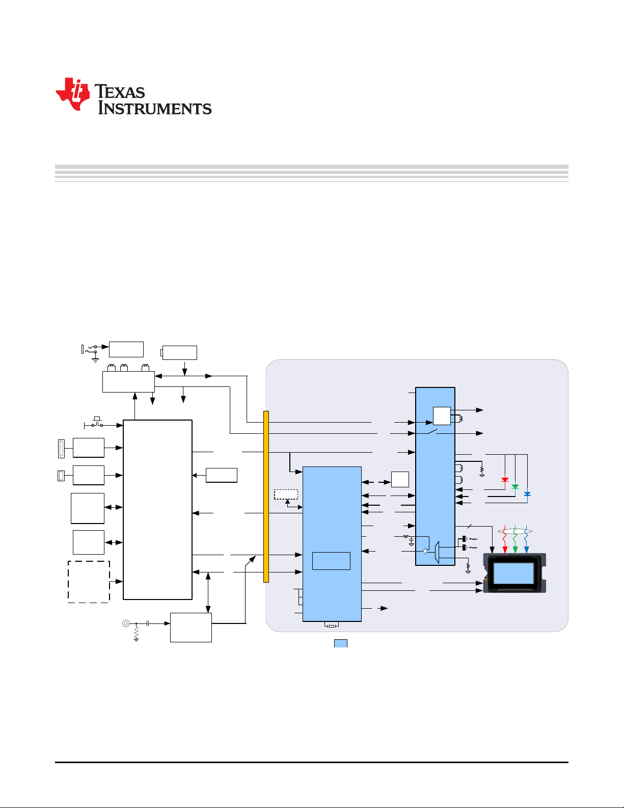
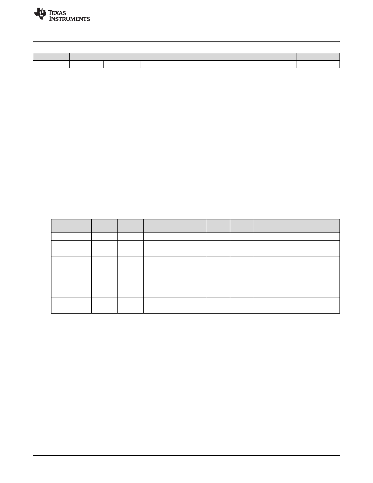
This guide details the software interface requirements for a DLPC343x ASIC-based system. It defines all
applicable communication protocols including I2C initialization, default settings and timing. The DLPC343x
system can be used in Figure 1.
Programmer's Guide
DLPU020C–July 2014–Revised May 2018
Figure 1. DLPC343x Embedded Configuration
2.1.1 I2C-Based Command Data Interface
The legacy interface configurations make use of an I2C interface for commands and a 24-bit parallel
interface.
DLPU020C–July 2014–Revised May 2018
Submit Documentation Feedback
Copyright © 2014–2018, Texas Instruments Incorporated
Programmer’s Guide
DLPC3430, DLPC3432, DLPC3435, DLPC3433, and DLPC3438 Software
7
Page 8

Interface Specification
3 Interface Specification
The protocol used in communicating information to DLPC343x consist of a serial data bus conforming to
the Philips I2C specification, up to 100 kHz. MIPI DSI is supported in DLPC343x, but this feature is not
supported in LightCrafter™ Display EVM.
3.1 I2C Interface and Ports for DLPC343x
DLPC343x commands are executed using I2C and support two I2C ports, port-0 and port-1.
Port-0 is primarily used for command and control interface. While using this port, DLPC343x behaves as
an I2C slave.
4 System Initialization
This section describes the methodology used for system initialization.
4.1 Boot ROM Concept
The DLPC343x employs a boot ROM and associated boot software. This resident boot code consists of
the minimum code necessary to complete the program loading. For most DLPC343x product
configurations, an external flash device can store the main application code, along with the other
configuration and operational data required by the system for normal operation.
4.2 Resident Boot Software
The resident boot code consists of the minimum code necessary to load the ARM software from flash to
internal RAM for execution.
www.ti.com
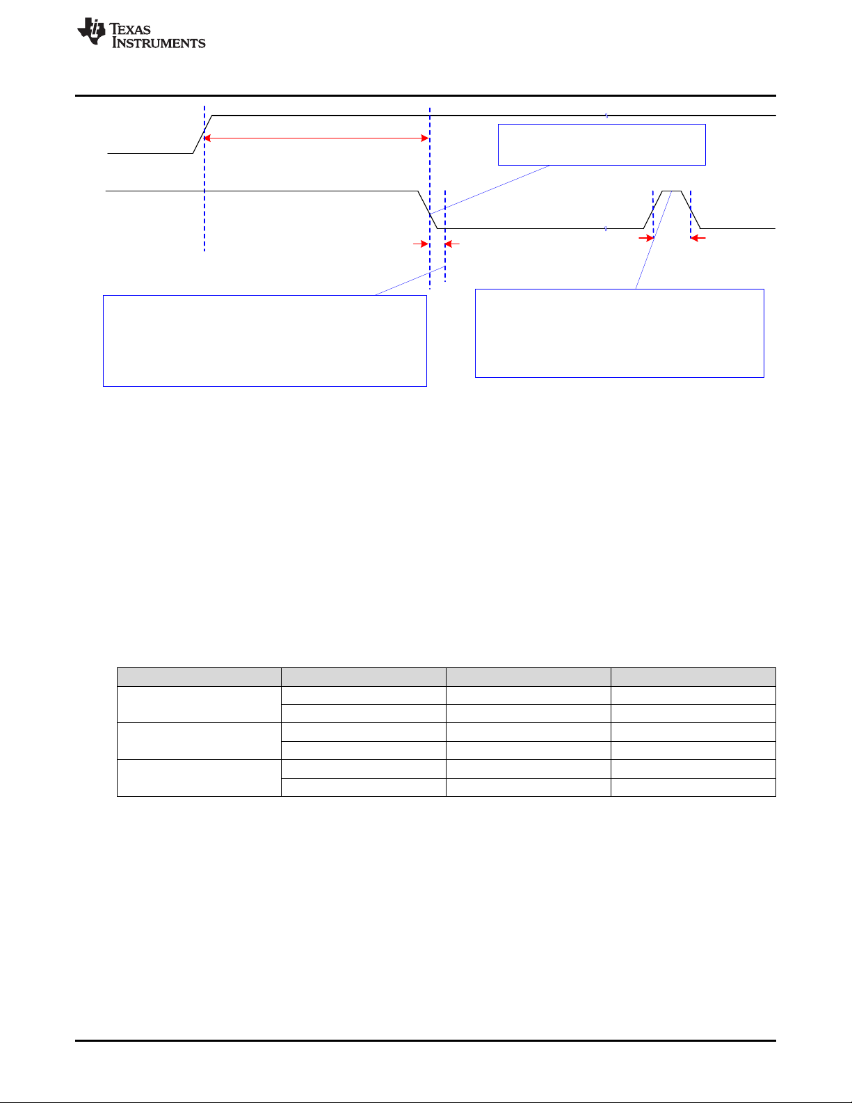
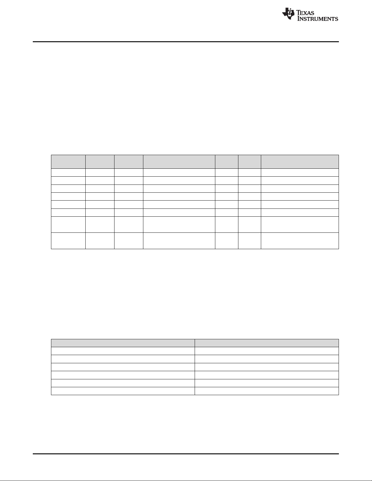
4.3 HOST_IRQ Initialization Sequence
HOST_IRQ is a signal indicating the status of DLPC343x initialization. While reset is applied, HOST_IRQ
resets to tri-state (an external pullup pulls the line high). HOST_IRQ remains tri-state (pulled high
externally) until the microprocessor boot completes. While the signal is pulled high, the controller performs
boot-up and auto-initialization.
Immediately after boot-up, the microprocessor drives HOST_IRQ to a logic high state to indicate that the
controller is performing auto-initialization (no real state change occurs on the external signal). Upon
completion of auto-initialization, ARM software sets HOST_IRQ to a logic low state to indicate the
completion of auto-initialization. At the falling edge, the system is said to enter the INIT_DONE state.
After auto-initialization completes, HOST_IRQ generates a logic high interrupt pulse to the host through
software control; this interrupt indicates that the controller detects an error condition or requires service.
8
DLPC3430, DLPC3432, DLPC3435, DLPC3433, and DLPC3438 Software
Programmer’s Guide
Copyright © 2014–2018, Texas Instruments Incorporated
DLPU020C–July 2014–Revised May 2018
Submit Documentation Feedback
Page 9
RESETZ
500 ms max
I2C access to DLPC343x should not start until HOST_IRQ goes low
(this should occur within 500 ms from the release of RESETZ.
HOST_IRQ
(with External Pullup)
0 ms min
(INIT_BUSY)
(ERR IRQ)
3 µs min
An active-high pulse on HOST_IRQ following the
initialization period will indicate an error condition has been
detected. The source of the error is reported in the system
status.
The first falling edge of HOST_IRQ
indicates auto-initialization done.
www.ti.com
5 Software Interface
There is generally one set of software commands supported by the DLPC343x controller.
Software Interface
Figure 2. HOST_IRQ Timing Diagram
5.1 I2C Considerations
5.1.1 I2C Transactions
5.1.1.1 Data Flow Control
5.1.2 List of System Write/Read Software Commands
Since all I2C commands are processed by software, only one type of I2C transaction is supported. This
transaction type is shown in Table 1 for both writes and reads. The I2C interface supports variably-sized
transactions for example, a one byte transaction, a nine byte transaction) to match the TI commands
discussed later in this document.
Table 1. I2C Write and Read Transactions
Transaction Address
Write
Read Request
Read Response
(1)
The address corresponds to the chip address of the controller.
(2)
The subaddress will correspond to a TI command.
(3)
The data (if present) will correspond to any required command parameters.
36h (or 3Ah) Command value Parameter values
36h (or 3Ah) Command value Parameter values
37h (or 3Bh) Parameter values
(1)
8-bits 8-bits 8-bit parameter bytes (0 → N)
8-bits 8-bits 8-bit parameter bytes (0 → N)
8-bits 8-bit parameter bytes (0 → N)
Sub-Address
While the I2C interface inherently supports flow control by holding the clock, this is not sufficient for all
transactions (for example, sequence and CMT updates). In this case, the host software should use the
(2)
Remaining Data Bytes
Read Short status to determine if the system is busy.
The commands supported by the I2C interfaces are discussed in the following sections.
(3)
DLPU020C–July 2014–Revised May 2018
Submit Documentation Feedback
Copyright © 2014–2018, Texas Instruments Incorporated
DLPC3430, DLPC3432, DLPC3435, DLPC3433, and DLPC3438 Software
Programmer’s Guide
9
Page 10

Software Interface
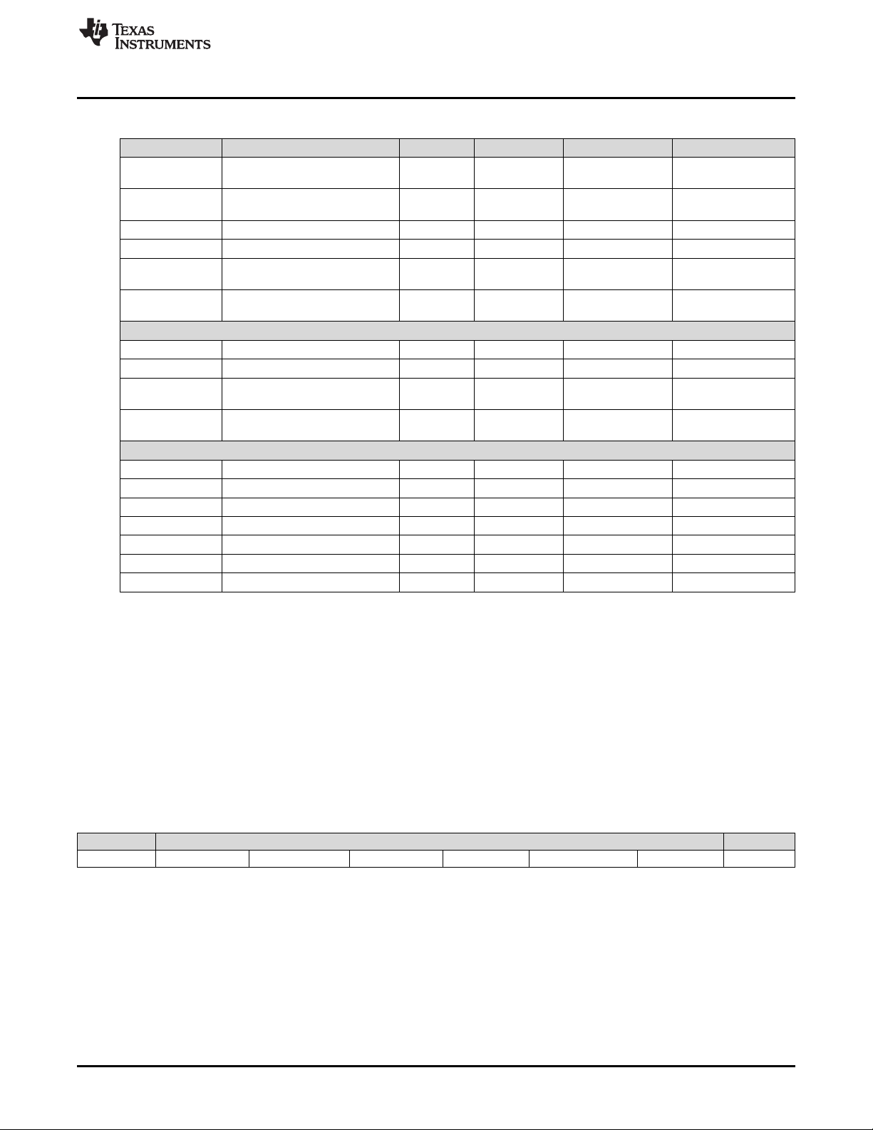
Command Type Command Description Reset Value OpCode (hex) Default Action Section
General Operation
Write Write Input Source Select 1 05 Test pattern Section 5.1.3.1
Write
Write Write Test Pattern Select 7000h 0B White solid field Section 5.1.3.5
Write Write Splash Screen Select 0D User-specified Section 5.1.3.7
Write Write Image Crop
Write Write Display Size DMD Res 12 Section 5.1.3.12
Write Write Display Image Orientation 14 User-specified Section 5.1.3.14
Write Write Display Image Curtain 1 16 Black Section 5.1.3.16
Write Write Image Freeze 0 1A No freeze Section 5.1.3.18
Write Write LOOK Select 22 User-specified Section 5.1.3.20
Write Write Execute Batch File 0 2D Section 5.1.3.24
Write Write External Input Image Size DMD Res 2E Section 5.1.3.25
Write Write Splash Screen Execute 35 Section 5.1.3.27
Illumination Control
Write
Write Write RGB LED Enable 7h 52 Enabled Section 5.1.3.30
Write Write RGB LED Current 54 User-specified Section 5.1.3.32
Write Write RGB LED Max Current 5C User-specified Section 5.1.3.35
Image Processing Control
Write
www.ti.com
Table 2. Supported TI Generic Commands
Read Read Input Source Select 06 Section 5.1.3.2
Write External Video Source
Format Select
Read Read Test Pattern Select 0C Section 5.1.3.6
Read Read Splash Screen Select 0E Section 5.1.3.8
Read Read Splash Screen Header 0F Section 5.1.3.9
Read Read Image Crop 11 Section 5.1.3.11
Read Read Display Size 13 Section 5.1.3.13
Read Read Display Image Orientation 15 Section 5.1.3.15
Read Read Display Image Curtain 17 Section 5.1.3.17
Read Read Image Freeze 1B Section 5.1.3.19
Read Read LOOK Select 23 Section 5.1.3.21
Read Sequence Header
Read
Attributes
Read DMD Sequencer Sync
Read
Mode
Read Read External Input Image Size 2F Section 5.1.3.26
Write LED Output Control
Method
Read LED Output Control
Read
Method
Read Read RGB LED Enable 53 Section 5.1.3.31
Read Read RGB LED Current 55 Section 5.1.3.33
Read CAIC LED Max Available
Read
Power
Read Read RGB LED Max Current 5D Section 5.1.3.36
Read Read CAIC RGB LED Current 5F Section 5.1.3.37
Write Local Area Brightness
Boost Control
Read Local Area Brightness
Read
Boost Control
43h 07 RGB888 Section 5.1.3.3
ffffffff000000
00h
1 80
10 No crop Section 5.1.3.10
26 Section 5.1.3.22
2C Section 5.1.3.23
50 User-specified Section 5.1.3.28
51 Section 5.1.3.29
57 Section 5.1.3.34
Manual strength
control
81 Section 5.1.3.39
Section 5.1.3.38
10
DLPC3430, DLPC3432, DLPC3435, DLPC3433, and DLPC3438 Software
Programmer’s Guide
Copyright © 2014–2018, Texas Instruments Incorporated
DLPU020C–July 2014–Revised May 2018
Submit Documentation Feedback
Page 11
www.ti.com
General Setup
Administrative Commands
Software Interface
Table 2. Supported TI Generic Commands (continued)
Command Type Command Description Reset Value OpCode (hex) Default Action Section
Write
Write Write CCA Control 1 86 Enabled Section 5.1.3.42
Write
Write Write Border Color 0 B2 Black Section 5.1.3.46
Write
Write CAIC Image Processing
Control
Read CAIC Image Processing
Read
Control
Read Read CCA Control 87 Section 5.1.3.43
Write Keystone Correction
Control
Read Keystone Correction
Read
Control
Read Read Border Color B3 Section 5.1.3.47
Write Keystone Projection Pitch
Angle
Read Keystone Projection Pitch
Read
Angle
Read Read Short Status D0 Section 5.1.3.50
Read Read System Status D1 Section 5.1.3.51
Read Read System Software Version D2 Section 5.1.3.52
Read Read Communication Status D3 Section 5.1.3.53
Read Read Controller Device ID D4 Section 5.1.3.54
Read Read DMD Device ID D5 Section 5.1.3.55
Read Read Flash Build Version D9 Section 5.1.3.56
0 88 Disabled Section 5.1.3.44
0 BB 0 Pitch angle Section 5.1.3.48
84 User-specified Section 5.1.3.40
85 Section 5.1.3.41
89 Section 5.1.3.45
BC Section 5.1.3.49
5.1.3 System Write/Read Commands
5.1.3.1 Write Input Source Select (05h)
5.1.3.1.1 Write
This command selects the image input source for the display module.
5.1.3.1.2 Write Parameters
Figure 3 describes the command parameters.
Figure 3. Write Parameters
MSB Byte 1 LSB
b7 b6 b5 b4 b3 b2 b1 b0
b(7:2)
Reserved
b(1:0) Input Source:
• 0h: External Video Port
• 1h: Test Pattern Generator
• 2h: Splash Screen
• 3h: Reserved
DLPU020C–July 2014–Revised May 2018
Submit Documentation Feedback
DLPC3430, DLPC3432, DLPC3435, DLPC3433, and DLPC3438 Software
Copyright © 2014–2018, Texas Instruments Incorporated
Programmer’s Guide
11
Page 12

Software Interface
Default: 01h
NOTE: When selecting the external video port, there is a set of associated commands applicable
These associations are also shown in Table 3.
www.ti.com
only to this source selection. These associated commands are the Write External Input
image Size and the Write External Video Source Format Select.
When selecting the test pattern generator, only one associated command is applicable to this
source selection. This associated command is the Write Test Pattern Select command.
When selecting the splash screen, only two associated commands are applicable to this
source selection. These associated commands are the Write Splash Screen Select and Write
splash Screen Execute commands.
12
DLPC3430, DLPC3432, DLPC3435, DLPC3433, and DLPC3438 Software
Programmer’s Guide
Copyright © 2014–2018, Texas Instruments Incorporated
DLPU020C–July 2014–Revised May 2018
Submit Documentation Feedback
Page 13

www.ti.com
Software Interface
Table 3. Source Specific Associated Commands
Source Specific Associated Commands
Write External Video Source Format Select Only N/A N/A
Write External Input Image Size Only N/A N/A
Write Test Pattern Select N/A Only N/A
Write Splash Screen Select N/A N/A Only
Write Splash Screen Execute N/A N/A Special
(1)
The Write Splash Screen Execute command is special in that there is no maintained state or history. Thus this command has no settings
to be stored and reused by the system.
External Video Port Test Pattern Generator Splash Screen
Input Source Select Options
These commands (other than Write Splash Screen Execute) describe the characteristics of their
associated source, and once these settings are defined the system stores them. Afterwards, each time an
input source selection is made (using the Write Input Source Select command), the system remembers
the settings described by the commands associated with the selected source, and automatically applies
them. The user only needs to send these associated commands when the source is first defined, or when
the source characteristics for that port must be changed. The appropriate associated commands must be
updated when source characteristics change.
The user can send source-associated commands every time they make an input source selection. The
source associated commands should be sent prior to sending the Write Input Source Select command.
When source-associated commands are sent when that source is not active, the controller software saves
the new settings, but does not execute these commands. When that source becomes active (via the Write
Input Source Select command), the controller applies these new settings, as in the following example:
1. The user sends the following commands (active input source = test pattern generator):
• Write image Freeze = freeze
• Write External Video Source Format Select (settings stored, command not executed)
• Write External Input Image Size (settings stored, command not executed)
• Write Input Source Select = external port (see step 2 below)
• Write Image Freeze = unfreeze
2. When the Write Input Source Select command is received, the software applies the settings from these
external video port-associated commands:
• External Video Source Format Select
• External input Image Size
If source-associated commands are sent for a source that is already active, the controller software
executes these commands when received, as in the following example:
• The user sends the following commands (active input source = external video port):
– Write Image Freeze = freeze
– Write external Video Source Format Select (command executed)
– Write Image Freeze = unfreeze
The rest of the commands that apply to image setup have settings applicable across all source selections,
and typically remain the same across the three input source selections. A few examples are Write Display
Size and Write Display Image Orientation. A representative list of these commands is shown in Table 4.
(1)
DLPU020C–July 2014–Revised May 2018
Submit Documentation Feedback
DLPC3430, DLPC3432, DLPC3435, DLPC3433, and DLPC3438 Software
Copyright © 2014–2018, Texas Instruments Incorporated
Programmer’s Guide
13
Page 14
Software Interface
www.ti.com
Table 4. Common Commands
Common Commands
Write Image Crop Common Common Common
Write Display Image Size Common Common Common
Write Keystone Correction Control Common Common Common
Write Display Image Orientation Common Common Common
Write Display Image Curtain Common Common Common
Write Look Select Common Common Common
Write Local Area Brightness Boost Control Common Common Common
Write CAIC Image Processing Control Common Common Common
External Video Port Test Pattern Generator Splash Screen
Input Source Select Options
While the values for these commands may be the same across the different input source types, the
hardware settings may change (for example: display image size = 1080p = DMD size – the external port
input source size is WXGA, which is scaled up to the display size of 1080p. If the user changes to the
TPG Input Source, the size of the test pattern must match the size of the DMD. Therefore, the scaler
settings must to be changed). The controller software manages the underlying hardware settings. This
also applies to those commands which specify automatic operation. While the automatic setting remains
the same, the underlying algorithm might change its settings based on the characteristic of the selected
source.
NOTE: The user is required to specify the active data size for all external input sources, using the
Write Input Image Size command.
NOTE: When a test pattern is selected, it is generated at the resolution of the DMD, modified by the
settings specified by the Write Image Crop command, and displayed at the resolution
specified by the Write Display Size command.
NOTE: The user should see the Write Image Freeze command for information on hiding on-screen
artifacts when selecting an input source.
5.1.3.2 Read Input Source Select (06h)
5.1.3.2.1 Read
This command reads the state of the image input source for the display module.
5.1.3.2.2 Read Parameters
This command has no command parameters.
5.1.3.2.3 Return Parameters
Figure 4 describes the return parameters.
14
DLPC3430, DLPC3432, DLPC3435, DLPC3433, and DLPC3438 Software
Programmer’s Guide
Copyright © 2014–2018, Texas Instruments Incorporated
DLPU020C–July 2014–Revised May 2018
Submit Documentation Feedback
Page 15
www.ti.com
Figure 4. Return Parameters
MSB Byte 1 LSB
b7 b6 b5 b4 b3 b2 b1 b0
Software Interface
b(7:2)
Reserved
b(1:0) Input source
• 0h: External video port
• 1h: Test Pattern generator
• 2h: Splash screen
• 3h: Reserved
5.1.3.3 Write External Video Source Format Select (07h)
5.1.3.3.1 Write
This command specifies the active external video port and the source data type for the display module.
5.1.3.3.2 Write Parameters
Table 5 describes the command parameters.
Table 5. Write Parameters
CMD Parameter Port Bits/Pixel Data Type
40h Parallel 16 RGB 565 16 1 Auto-select RGB CSC
41h Parallel 18 RGB 666 18 1 Auto-select RGB CSC
42h Parallel 24 RGB 888 8 3 Auto-select RGB CSC
43h Parallel 24 RGB 888 24 1 Auto-select RGB CSC
50h Parallel 18 YCbCr 666 18 1 Auto-select YCbCr CSC
51h Parallel 24 YCbCr 888 24 1 Auto-select YCbCr CSC
60h Parallel 16 YCbCr 4:2:2 88 8 2
61h Parallel 16 YCbCr 4:2:2 88 16 1
Bus
Width
Clks/Pix
el
Notes
Auto-select YCbCr CSC
Auto-select 4:2:2 → 4:4:4
Auto-select YCbCr CSC
Auto-select 4:2:2 → 4:4:4
Default: 43h
This command is used in conjunction with the Write Input Source Select command. This command
specifies which input port displays when the Write Input Source Select command selects external video
port as the image source. The settings for this command are retained until changed using this command.
These settings are automatically applied each time the external video port is selected.
When the external video port is selected as the input source, the software automatically selects and loads
the proper CSC, based on the selected parameter of this command (appropriate matrix for RGB, selected
matrix for YCbCr including offset).The appropriate data path is also automatically selected for 4:2:2 versus
4:4:4 processing.
The selection of video source port is independent from the selected command port.
The user should review the notes for the Write Input Source Select command to understand the concept
of source-associated commands. This concept determines when source-associated commands are
executed by the system. This command is a source-associated command.
DLPU020C–July 2014–Revised May 2018
Submit Documentation Feedback
DLPC3430, DLPC3432, DLPC3435, DLPC3433, and DLPC3438 Software
Copyright © 2014–2018, Texas Instruments Incorporated
Programmer’s Guide
15
Page 16
Software Interface
5.1.3.4 Read External Video Source Format Select (08h)
5.1.3.4.1 Read
This command reads the state of the active external video port and the source data type for the display
module.
5.1.3.4.2 Read Parameters
This command has no read parameters.
5.1.3.4.3 Return Parameters
Table 6 describes the return parameters.
Table 6. Return Parameters
www.ti.com
CMD
Parameter
40h Parallel 16 RGB 565 16 1 Auto-select RGB CSC
41h Parallel 18 RGB 666 18 1 Auto-select RGB CSC
42h Parallel 24 RGB 888 8 3 Auto-select RGB CSC
43h Parallel 24 RGB 888 24 1 Auto-select RGB CSC
50h Parallel 18 YCbCr 666 18 1 Auto-select YCbCr CSC
51h Parallel 24 YCbCr 888 24 1 Auto-select YCbCr CSC
60h Parallel 16 YCbCr 4:2:2 88 8 2
61h Parallel 16 YCbCr 4:2:2 88 16 1
Port Bits/Pixel Data Type
5.1.3.5 Write Test Pattern Select (0Bh)
5.1.3.5.1 Write
This command specifies an internal test pattern for display on the display module.
5.1.3.5.2 Write Parameters
Table 7 describes the command parameters.
Bus
Width
Table 7. Write Parameters
Clks/Pix
el
Notes
Auto-select YCbCr CSC
Auto-select 4:2:2 → 4:4:4
Auto-select YCbCr CSC
Auto-select 4:2:2 → 4:4:4
16
Parameter Bytes Description
Byte 1 TPG pattern select
Byte 2 Foreground and background color (see Table 8)
Byte 3 Parameter 1 (see Table 9)
Byte 4 Parameter 2 (see Table 9)
Byte 5 Parameter 3 (see Table 9)
Byte 6 Parameter 4 (see Table 9)
DLPC3430, DLPC3432, DLPC3435, DLPC3433, and DLPC3438 Software
Programmer’s Guide
Copyright © 2014–2018, Texas Instruments Incorporated
DLPU020C–July 2014–Revised May 2018
Submit Documentation Feedback
Page 17

www.ti.com
Figure 5. Byte 1 Write Parameter
MSB Byte 1 LSB
b7 b6 b5 b4 b3 b2 b1 b0
Software Interface
b(7)
Test pattern border:
• 00h: Disabled
• 01h: Enabled
b(6:4) Reserved
b(3:0) Left pattern select:
• 00h: Solid field
• 01h: Fixed step horizontal ramp
• 02h: Fixed step vertical ramp
• 03h: Horizontal lines
• 04h: Diagonal lines
• 05h: Vertical lines
• 06h: Horizontal and vertical grid
• 07h: Checkerboard
• 08h: Color bars
• 09h-0Fh: Reserved
Byte 1 default: 00h
Figure 6. Byte 2 Write Parameter
MSB Byte 2 LSB
b7 b6 b5 b4 b3 b2 b1 b0
b(7)
Reserved
b(6:4) Foreground color:
• 0h: Black
• 1h: Red
• 2h: Green
• 3h: Blue
• 4h: Cyan
• 5h: Magenta
• 6h: Yellow
• 7h: White
b(3:0) Reserved
b(2:0) Background color:
• 0h: Black
• 1h: Red
• 2h: Green
• 3h: Blue
• 4h: Cyan
• 5h: Magenta
• 6h: Yellow
• 7h: White
DLPU020C–July 2014–Revised May 2018
Submit Documentation Feedback
DLPC3430, DLPC3432, DLPC3435, DLPC3433, and DLPC3438 Software
Copyright © 2014–2018, Texas Instruments Incorporated
Programmer’s Guide
17
Page 18
Software Interface
www.ti.com
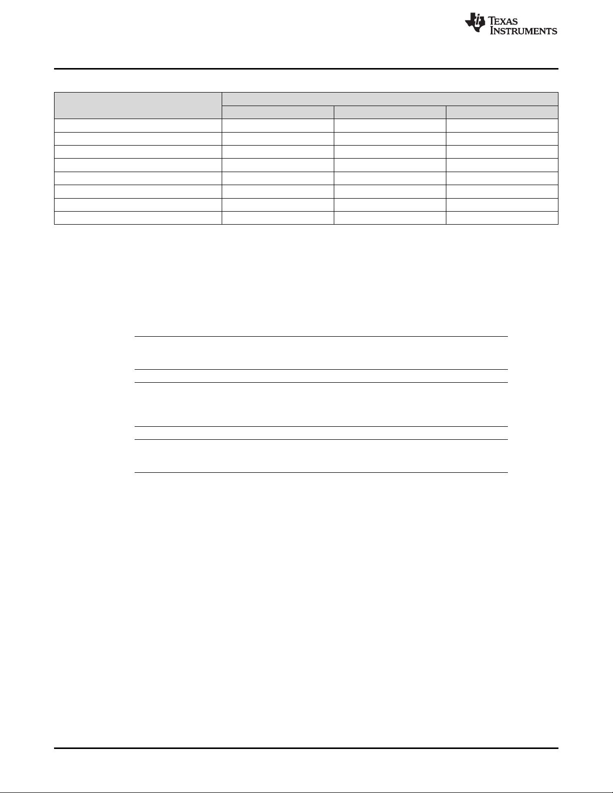
Table 8. Foreground and Background Color Use
Pattern
Solid field Yes No
Fixed step horizontal ramp Yes No
Fixed step vertical ramp Yes No
Horizontal lines Yes Yes
Vertical lines Yes Yes
Diagonal lines Yes Yes
Grid lines Yes Yes
Checkerboard Yes Yes
Color bars No No
Foreground Color Background Color
Byte 2
Byte 2 default: 70h
Table 9. Descriptions and Bit Assignments for Parameters 1-4
Pattern
Solid field N/A N/A N/A N/A
Fixed step
horizontal ramp
Fixed step
vertical ramp
Horizontal lines N/A N/A
Vertical lines N/A N/A
Diagonal lines N/A N/A Vertical spacing 8 Horizontal spacing 8
Grid lines
Checkerboard
Color bars N/A N/A N/A N/A
Byte 6 (Parameter 4) Byte 5 (Parameter 3) Byte 4 (Parameter 2) Byte 3 (Parameter 1)
Description Bits Description Bits Description Bits Description Bits
N/A N/A End value 8 Start value 8
N/A N/A End value 8 Start value 8
Vertical
background line
width
Number of vertical
checkers
Vertical foreground
8
3
line width
Number of vertical
checkers
Background line
Background line
8
8
Horizontal
background line
Number of
horizontal checkers
width
width
width
8 Foreground line width 8
8 Foreground line width 8
Horizontal foreground
8
3
line width
Number of horizontal
checkers
8
8
18
This command is used in conjunction with the Write Input Source Select command. This command
specifies which test pattern displays when the Write Input Source Select command selects test pattern
generator as the image source. The settings for this command are retained until changed using this
command. These settings automatically apply each time the test pattern generator is selected.
Batch files are created and stored in flash, and recall the settings for predefined test patterns.
Test patterns are created at the resolution of the display (DMD), are modified by the Write Image Crop
command, and displayed at the resolution specified by the Write Display Size command.
Test patterns display at the default frame rate 60 Hz.
The Test Pattern Border Selection creates a white border, a single pixel wide and tall, around the specified
test pattern.
The user must review the notes for the Write Input Source Select command to understand the concept of
source-associated commands. This concept determines when source-associated commands are executed
by the system. This command is a source-associated command.
When a foreground or background color is not used, the bit values are ignored (see Table 8). If both
foreground and background color are not used, or when a parameter byte (bytes 3 thru 6) is not used, the
byte should not be sent. Table 10 shows the number of bytes required, based on the specified pattern.
DLPC3430, DLPC3432, DLPC3435, DLPC3433, and DLPC3438 Software
Programmer’s Guide
Copyright © 2014–2018, Texas Instruments Incorporated
DLPU020C–July 2014–Revised May 2018
Submit Documentation Feedback
Page 19

www.ti.com
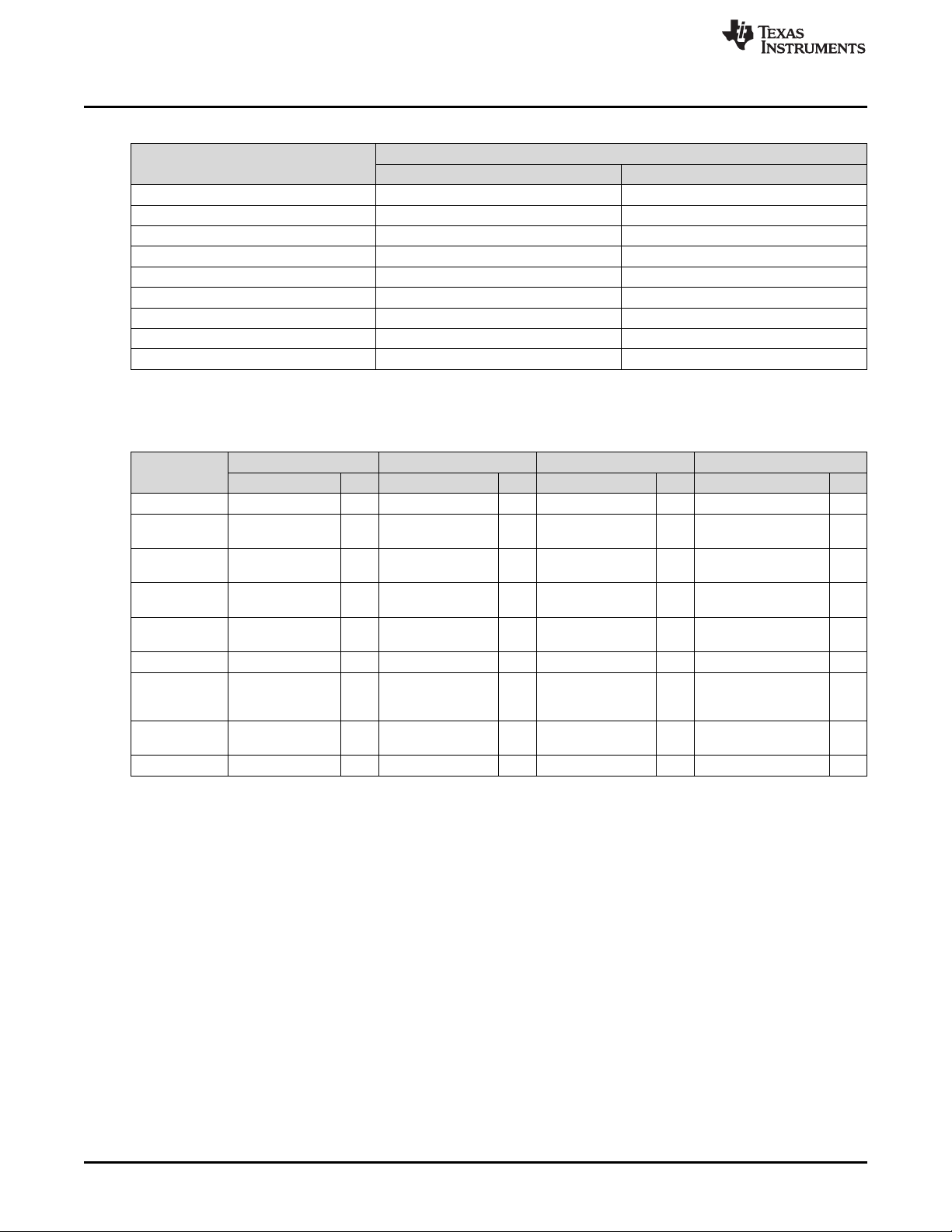
As noted in Table 8, the color for the solid field pattern is specified using the foreground color. An example
of a solid field pattern is shown in Figure 7.
Software Interface
Table 10. Number of Bytes Required based on Pattern Selection
Specified Pattern Number of Bytes Required
Solid field 2
Fixed step horizontal ramp 4
Fixed step vertical ramp 4
Horizontal lines 4
Vertical lines 4
Diagonal lines 4
Grid lines 6
Checkerboard 7
Color bars 1
Figure 7. Example of Solid Field Test Pattern (Red)
As noted in Table 8, the color for the fixed step horizontal ramp pattern is specified using the foreground
color. As noted in Table 9, the user specifies the start value and the stop value for the ramp. For this
pattern, the system automatically determines the step size based on the start and stop values and the size
of the display (DMD). The minimum start value is 0, the maximum stop value is 255, and the start value
must always be smaller than the stop value. For example, if the start value = 0, the stop value = 255, and
the DMD resolution is 1280 wide, the step size would be 5 (1280 pixels / 256 values = 5). Thus every gray
shade value from 0 to 255 would have a step size of 5 pixels (such that each step would have 5 columns
of pixels with the same gray scale value). The gray scale value always increments by 1 for each step
between the start and stop values. An example of a fixed step horizontal ramp pattern is shown in
Figure 8.
DLPU020C–July 2014–Revised May 2018
Submit Documentation Feedback
DLPC3430, DLPC3432, DLPC3435, DLPC3433, and DLPC3438 Software
Copyright © 2014–2018, Texas Instruments Incorporated
Programmer’s Guide
19
Page 20

Software Interface
As noted in Table 8, the color for the fixed step vertical ramp pattern is specified using the foreground
color. As noted in Table 9, the user specifies the start value and the stop value for the ramp. For this
pattern, the system automatically determines the step size based on the start and stop values and the size
of the display (DMD). The minimum start value = 0, the maximum stop value = 255, and the start value
must always be smaller than the stop value. For example, if the start value = 0, the stop value = 255, and
the DMD resolution is 768 tall, then the step size would be 3 (768 pixels / 256 values = 3). Thus every
value from 0 to 255 would have a step size of 3 pixels (such that each step would have 3 rows of pixels
with the same gray scale value). The gray scale value always increments by 1 for each step between the
start and stop values. An example of a fixed step vertical ramp pattern is shown in Figure 9.
www.ti.com
Figure 8. Example of Fixed Step Horizontal Ramp Test Pattern
20
Figure 9. Example of Fixed Step Vertical Ramp Test Pattern
DLPC3430, DLPC3432, DLPC3435, DLPC3433, and DLPC3438 Software
Programmer’s Guide
Copyright © 2014–2018, Texas Instruments Incorporated
DLPU020C–July 2014–Revised May 2018
Submit Documentation Feedback
Page 21
www.ti.com
As noted in Table 8, the colors for the horizontal lines pattern are specified using both the foreground and
background colors. The foreground color is used for the horizontal lines, and the background color is used
for the space between the lines. As noted in Table 9, the user specifies the foreground line width, as well
as the background line width. The user must determine the line spacing for each resolution display. For
example, if the foreground line width = 1, and the background line width = 9, there would be a single pixel
horizontal line on every tenth line. An example of a horizontal lines pattern is shown in Figure 10.
Software Interface
Figure 10. Example of Horizontal Lines Test Pattern
As noted in Table 8, the colors for the vertical lines pattern are specified using both the foreground and
background colors. The foreground color is used for the vertical lines, and the background color is used
for the space between the lines. As noted in Table 9, the user specifies the foreground line width, as well
as the background line width. The user must determine the line spacing for each resolution display. For
example, if the foreground line width = 1, and the background line width = 9, there would be a single pixel
vertical line on every tenth line. An example of a vertical lines pattern is shown in Figure 11.
Figure 11. Example of Vertical Lines Test Pattern
DLPU020C–July 2014–Revised May 2018
Submit Documentation Feedback
DLPC3430, DLPC3432, DLPC3435, DLPC3433, and DLPC3438 Software
Copyright © 2014–2018, Texas Instruments Incorporated
Programmer’s Guide
21
Page 22
HORZSPACING
VERTSPACING
Software Interface
As noted in Table 8, the colors for the diagonal lines pattern are specified using both the foreground and
background colors. The foreground color is used for the diagonal lines, and the background color is used
for the space between the lines. As noted in Table 9, the user specifies the horizontal and vertical line
spacing. The line width is always one pixel. The user determines the line spacing for each resolution
display. Both horizontal and vertical line spacing must use the same value, and are limited to values of 3,
7, 15, 31, 63, 127, and 255. Invalid values result in a communication error (invalid command parameter).
An example of a diagonal lines pattern is shown in Figure 12.
www.ti.com
Figure 12. Example of Diagonal Lines Test Pattern
As noted in Table 8, the colors for the grid lines pattern are specified using both the foreground and
background colors. The foreground color is used for the grid lines, and the background color is used for
the space between the lines. As noted in Table 9, the user specifies the horizontal foreground and
background line width, as well as the vertical foreground and background line width. The user determines
the line spacing for each resolution display. For example, if the horizontal foreground line width = 1, and
background line width = 9, there would be a single pixel horizontal line on every tenth line. If the vertical
foreground line width = 1, and background line width = 9, there would be a single pixel vertical line on
every tenth line. An example of a grid lines pattern is shown in Figure 13.
22
DLPC3430, DLPC3432, DLPC3435, DLPC3433, and DLPC3438 Software
Programmer’s Guide
Copyright © 2014–2018, Texas Instruments Incorporated
DLPU020C–July 2014–Revised May 2018
Submit Documentation Feedback
Page 23

www.ti.com
Software Interface
Figure 13. Example of Grid Lines Test Pattern
As noted in Table 8, the colors for the checkerboard pattern are specified using both the foreground and
background colors. The foreground color is used for one of the checkers, and the background color is
used for the alternating checker. As noted in Table 9, the user specifies the number of horizontal checkers
and the number of vertical checkers. For this pattern, the system automatically determines the checker
size in each direction based on the number of checkers and the size of the display (DMD). For example, if
the number of horizontal checkers = 4, the number of vertical checkers = 4, and the DMD resolution is
1280x720, the size of the horizontal checkers is 320 pixels, and the size of the vertical checkers is 180
pixels (1280 pixels / 4 checkers = 320 pixels: 720 pixels / 4 checkers = 180 pixels). An example of a
checkerboard pattern (16 checkers by 12 checkers) is shown in Figure 14.
Figure 14. Example of Checkerboard Test Pattern
DLPU020C–July 2014–Revised May 2018
Submit Documentation Feedback
DLPC3430, DLPC3432, DLPC3435, DLPC3433, and DLPC3438 Software
Copyright © 2014–2018, Texas Instruments Incorporated
Programmer’s Guide
23
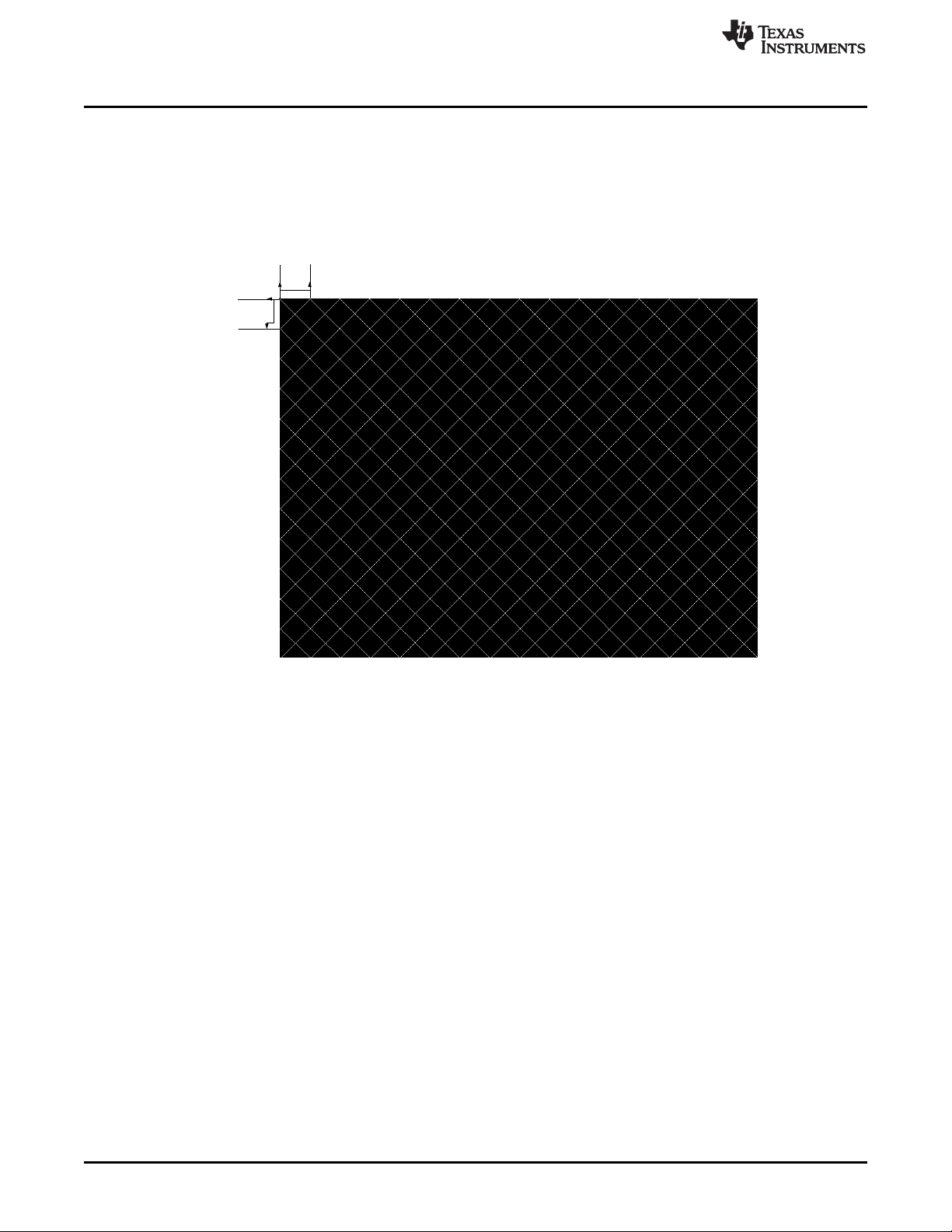
Page 24

Software Interface
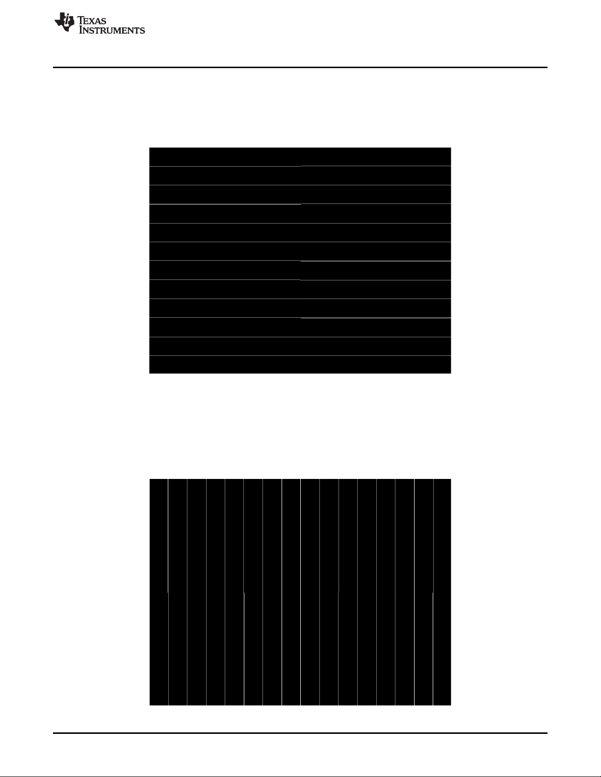
As noted in Table 8 and Table 9, there is no user programmability associated the color bars test pattern.
This pattern is made up of eight vertical color bars: white, yellow, cyan, green, magenta, red, blue, and
black. For this pattern, the system automatically determines the width for each color bar based on the size
of the display (DMD). An example of the color bars pattern is shown in Figure 15.
www.ti.com
Figure 15. Example of Color Bars Test Pattern
5.1.3.6 Read Test Pattern Select (0Ch)
5.1.3.6.1 Read
This command reads the state of the test pattern select command for the display module.
5.1.3.6.2 Read Parameters
This command has no read parameters.
5.1.3.6.3 Return Parameters
Figure 16 describes the return parameters.
Figure 16. Return Parameters
MSB Byte 1 LSB
b7 b6 b5 b4 b3 b2 b1 b0
Table 11. Parameter Bytes
Parameter Bytes Description
Byte 1 TPG pattern select
Byte 2 Foreground and background color (see Table 8)
Byte 3 Parameter 1 (see Table 9)
Byte 4 Parameter 2 (see Table 9)
Byte 5 Parameter 3 (see Table 9)
Byte 6 Parameter 4 (see Table 9)
24
DLPC3430, DLPC3432, DLPC3435, DLPC3433, and DLPC3438 Software
Programmer’s Guide
Copyright © 2014–2018, Texas Instruments Incorporated
DLPU020C–July 2014–Revised May 2018
Submit Documentation Feedback
Page 25

www.ti.com
This command always returns six bytes, since the host does not know how many bytes are valid until the
pattern is selected. All unnecessary bytes (see Table 10) are set to 0.
If a batch file is used to specify the parameters of the test pattern generator, those parameters are
returned by this command.
5.1.3.7 Write Splash Screen Select (0Dh)
5.1.3.7.1 Write
This command selects a stored splash screen to be displayed on the display module.
5.1.3.7.2 Write Parameters
Table 12 describes the command parameters.
Parameter Bytes Description
Byte 1 Splash screen reference number (integer)
Default: User defined
This command is used in conjunction with the Write Input Source Select and the Write Splash Screen
Execute commands, and specifies which splash screen is selected by the Input Source Select command.
The settings for this command are retained until changed using this command.
The steps required to display a splash screen are:
1. Select the desired splash screen (using this command)
2. Change the input source to splash screen (using Write Input Source Select)
3. Start the splash screen retrieval process (using Write Splash Screen Execute).
The splash screen is read from flash and sent down the processing path of the controller once, to be
stored in memory for display at the end of the processing path. As such, all image processing settings
(such as image crop, image orientation, display size, splash screen select, splash screen as input source,
and so forth) should be set by the user before executing the Write Splash Screen Execute command.
The user should review the notes for the Write Input Source Select command to understand the concept
of source-associated commands. This concept determines when source-associated commands are
executed by the system. This command is a source-associated command.
The availability of the splash screen is limited by the available space in flash memory. All splash screens
must be landscape oriented.
For single-controller applications which support DMD resolutions of up to 1280 x 720, the minimum splash
image size allowed for flash storage is 427 x 240, with the maximum being the resolution of the product
DMD. Typical splash image sizes for flash are 427 x 240 and 640 x 360. The full resolution size is typically
used to support an optical test splash screen.
For dual-controller applications which support DMD resolutions up to 1980 x 1080, the minimum splash
image size allowed for flash storage is 854 x 480, with the maximum being the resolution of the product
DMD. Typical splash image sizes for flash are 854 x 480. The full resolution size is typically used to
support an optical test splash screen.
The user must specify how the splash image is displayed on the screen. Key commands for this are Write
Image Crop and Write Display Size.
When this command is received while splash screen is the active source, other than storing the specified
splash screen value, the only action taken by the controller software is to obtain the header information
from the selected splash screen and store this in internal memory. When the Write Splash Screen Execute
command is received, the controller software uses this stored information to set up the processing path
prior to pulling the splash data from flash.
Software Interface
Table 12. Write Parameters
DLPU020C–July 2014–Revised May 2018
Submit Documentation Feedback
DLPC3430, DLPC3432, DLPC3435, DLPC3433, and DLPC3438 Software
Copyright © 2014–2018, Texas Instruments Incorporated
Programmer’s Guide
25
Page 26
Software Interface
5.1.3.8 Read Splash Screen Select (0Eh)
5.1.3.8.1 Read
This command reads the state of the Splash Screen Select command of the display module.
5.1.3.8.2 Read Parameters
This command has no command parameters.
5.1.3.8.3 Return Parameters
Table 13 describes the return parameters.
Table 13. Return Parameters
Parameter Bytes Description
Byte 1 Splash screen selected (integer)
5.1.3.9 Read Splash Screen Header (0Fh)
5.1.3.9.1 Read
This command reads the splash screen header information for the selected splash screen of the display
module.
www.ti.com
5.1.3.9.2 Read Parameters
The read parameter specifies the splash screen for which the header parameters are returned. If a splash
screen value is provided for an unavailable splash screen, this is considered an error (invalid command
parameter value – communication status) and the command is be executed.
Parameter Bytes Description
5.1.3.9.3 Return Parameters
Table 15 describes the return parameters.
Parameter Bytes Description
Byte 10 Compression type
Byte 11 Color order
Byte 12 Chroma order
Table 14. Read Parameters
Byte 1 Splash screen reference number (integer)
Table 15. Return Parameters
Byte 1 Splash image width in pixels (LSByte)
Byte 2 Splash image width in pixels (MSByte)
Byte 3 Splash image height in pixels (LSByte)
Byte 4 Splash image height in pixels (MSByte)
Byte 5 Splash image size in bytes (LSByte)
Byte 6 Splash image size in bytes
Byte 7 Splash image size in bytes
Byte 8 Splash image size in bytes (MSByte)
Byte 9 Pixel format
26
DLPC3430, DLPC3432, DLPC3435, DLPC3433, and DLPC3438 Software
Programmer’s Guide
Copyright © 2014–2018, Texas Instruments Incorporated
DLPU020C–July 2014–Revised May 2018
Submit Documentation Feedback
Page 27

www.ti.com
Parameter definitions are referenced in Table 16.
Table 15. Return Parameters (continued)
Parameter Bytes Description
Byte 13 Byte order
Table 16. Splash Screen Header Definitions
Parameter Values
0h = 24-bit RGB unpacked (not used)
Pixel format
Compression type
Color order
Chroma order
Byte order
1h = 24-bit RGB packed (not used)
2h = 16-bit RGB 5-6-5
3h = 16-bit YCbCr 4:2:2
0h = Uncompressed
1h = RGB RLE compressed
2h = User-defined (not used)
3h = YUV RLE compressed
0h = 00RRGGBB
1h = 00GGRRBB
0h = Cr is first pixel
1h = Cb is first pixel
0h = Little endian
1h = Big endian
Software Interface
5.1.3.10 Write Image Crop (10h)
5.1.3.10.1 Write
This command specifies which portion of the input image is captured and output from the cropping
function of the display module.
5.1.3.10.2 Write Parameters
Table 17 describes the command parameters.
Parameter Bytes Description
Byte 1 Capture start pixel (LSByte)
Byte 2 Capture start pixel (MSByte)
Byte 3 Capture start line (LSByte)
Byte 4 Capture start line (MSByte)
Byte 5 Pixels per line (LSByte)
Byte 6 Pixels per line (MSByte)
Byte 7 Lines per frame (LSByte)
Byte 8 Lines per frame (MSByte)
Default: Bytes (8:1) = FFh FFh FFh FFh 00h 00h 00h 00h (no cropping)
The capture start parameters for this command are referenced to active data, and are 0-based (such that
specifying the capture start pixel to be a value of zero indicates the first active pixel of a line). The
pixel/line and lines/frame parameters are 1-based (such that specifying the pixels/line value to be a value
of 640 indicates 640 pixels to be captured).
Table 17. Write Parameters
DLPU020C–July 2014–Revised May 2018
Submit Documentation Feedback
DLPC3430, DLPC3432, DLPC3435, DLPC3433, and DLPC3438 Software
Copyright © 2014–2018, Texas Instruments Incorporated
Programmer’s Guide
27
Page 28

Software Interface
This command applies to all sources including test patterns, splash screens, and external sources. Making
a change to the source or port does not impact the application of this command.
Cropping is done prior to the scaling function in the display module. As such, the size difference between
the crop size and display size determines the amount of scaling needed in both dimensions. The scaling
limits are listed in Table 18.
www.ti.com
Table 18. Scaling Limits
Controller Configuration
Single controller (excluding
interlaced NTSC/PAL)
Single controller (interlaced
NTSC/PAL only)
Dual controller
Maximum Horizontal
Interpolation Scale
Factor
3.0 3.0 3.0 3.0
3.0 3.0 3.0 6.0
Scaling not supported
except for splash
screen.
Maximum Horizontal
Decimation Scale
Factor
Scaling not supported
except for splash
screen.
Maximum Vertical
Interpolation Scale
Factor
Scaling not supported
except for splash
screen.
Maximum Vertical
Decimation Scale
Factor
Scaling not supported
except for splash
screen.
The scaling limits noted in Table 18 may not be possible depending on other factors, such as keystone
correction. In this case, the system does what is requested even if this results in a broken image. The
OEM is responsible for providing the appropriate input settings to meet the display needs.
If a crop size parameter exceeds the size of the input image, the input image size minus the capture start
pixel/line is be used (as shown in Figure 17). The crop size parameters returned by the read image crop
command are always the values specified by the Write Image Crop command.
Figure 17. Cropping Rules when Crop Size exceeds Input Size
5.1.3.11 Read Image Crop (11h)
5.1.3.11.1 Read
This command reads the state of the image crop command for the display module.
5.1.3.11.2 Read Parameters
This command has no command parameters.
5.1.3.11.3 Return Parameters
Table 19 describes the return parameters.
Table 19. Return Parameters
Parameter Bytes Description
Byte 1 Capture start pixel (LSByte)
Byte 2 Capture start pixel (MSByte)
28
DLPC3430, DLPC3432, DLPC3435, DLPC3433, and DLPC3438 Software
Programmer’s Guide
Copyright © 2014–2018, Texas Instruments Incorporated
DLPU020C–July 2014–Revised May 2018
Submit Documentation Feedback
Page 29

www.ti.com
Parameter Bytes Description
Byte 3 Capture start line (LSByte)
Byte 4 Capture start line (MSByte)
Byte 5 Pixels per line (LSByte)
Byte 6 Pixels per line (MSByte)
Byte 7 Lines per frame (LSByte)
Byte 8 Lines per frame (MSByte)
All parameters for this command are referenced to active data, and are 1-based. (such that specifying the
capture start pixel to be a value of one indicates the first active pixel of a line).
5.1.3.12 Write Display Size (12h)
5.1.3.12.1 Write
This command specifies the size of the active image to be displayed on the display module.
5.1.3.12.2 Write Parameters
Table 20 describes the command parameters.
Software Interface
Table 19. Return Parameters (continued)
Table 20. Write Parameters
Parameter Bytes Description
Byte 1 Pixels per line (LSByte)
Byte 2 Pixels per line (MSByte)
Byte 3 Lines per frame (LSByte)
Byte 4 Lines per frame (MSByte)
Default: DMD resolution.
This command specifies the size of the non-keystone corrected image to be output from the scaler
function, which is the size of the active displayed image.
The parameter values are to be 1-based. (such that a value of 1280 pixels displays 1280 pixels per line).
All sub-images (images smaller than the DMD display) are horizontally and vertically centered on the
display (DMD).
If the display size exceeds the resolution of the DMD, this is considered an error (invalid command
parameter value – communication status) and the command does not execute. The display size
parameters are checked against the DMD resolution in both rotation image orientations (non-rotated and
rotated), and if the DMD resolution is exceeded in both of these orientations, it is considered an error. The
system does not check for proper image orientation setup.
DMD resolution = 854 × 480:
• Example 1: Display size parameter = 480 × 854 (not an error)
• Example 2: Display size parameter = 900 × 320 (error)
• Example 3: Display size parameter = 500 × 600 (error)
If the source, crop, and display parameter combinations exceed the capabilities of the scaler, the system
implements the user request as best it can, and the displayed image may be broken. The user must
provide updated parameters to fix the image.
DLPU020C–July 2014–Revised May 2018
Submit Documentation Feedback
DLPC3430, DLPC3432, DLPC3435, DLPC3433, and DLPC3438 Software
Copyright © 2014–2018, Texas Instruments Incorporated
Programmer’s Guide
29
Page 30

Software Interface
5.1.3.13 Read Display Size (13h)
5.1.3.13.1 Read
This command reads the state of the display size command for the display module.
5.1.3.13.2 Read Parameters
This command has no read parameters.
5.1.3.13.3 Return Parameters
Table 21 describes the return parameters.
Parameter Bytes Description
Byte 1 Pixels per line (LSByte)
Byte 2 Pixels per line (MSByte)
Byte 3 Lines per frame (LSByte)
Byte 4 Lines per frame (MSByte)
The parameter values are 1-based. (such that a value of 1280 pixels displays 1280 pixels per line).
www.ti.com
Table 21. Return Parameters
5.1.3.14 Write Display Image Orientation (14h)
5.1.3.14.1 Write
This command specifies the image orientation of the displayed image for the display module.
5.1.3.14.2 Write Parameters
Figure 18 describes the command parameters.
Figure 18. Write Parameters
MSB Byte 1 LSB
b7 b6 b5 b4 b3 b2 b1 b0
b(7:3)
Reserved
b(2) Short axis image flip:
• 0: Image not flipped.
• 1: Image flipped.
b(1) Long axis image flip:
• 0: Image not flipped.
• 1: Image flipped.
b(0) Image rotation (for portrait source only):
• 0: No rotation
• 1: Minus 90° rotation
30
DLPC3430, DLPC3432, DLPC3435, DLPC3433, and DLPC3438 Software
Programmer’s Guide
Copyright © 2014–2018, Texas Instruments Incorporated
DLPU020C–July 2014–Revised May 2018
Submit Documentation Feedback
Page 31

Flip Disabled Flip EnabledDMD
Flip Disabled Flip EnabledDMD
Non-Rotated Display -90o Rotated Display
www.ti.com
Default: User-defined
Figure 19 shows the result of non-rotation and rotation of a portrait source. If a portrait image is not
rotated, it is centered and padded with black bars.
Landscape images typically should not be rotated, but the system allows this as it may be appropriate for
some situations or configurations. The user is responsible for determining if the result is acceptable.
Image rotation is allowed while keystone correction is enabled, though it may not be appropriate for all
situations or configurations. The user is responsible for determining if the result is acceptable.
Software Interface
Figure 19. Rotation and Non-Rotation of Portrait Source
Figure 20. Long-Axis Flip
Figure 21 shows the short-axis flip.
Figure 21. Short-Axis Flip
5.1.3.15 Read Display Image Orientation (15h)
5.1.3.15.1 Read
This command reads the state of the displayed image orientation function for the display module.
5.1.3.15.2 Read Parameters
This command has no read parameters.
DLPU020C–July 2014–Revised May 2018
Submit Documentation Feedback
DLPC3430, DLPC3432, DLPC3435, DLPC3433, and DLPC3438 Software
Copyright © 2014–2018, Texas Instruments Incorporated
Programmer’s Guide
31
Page 32

Software Interface
5.1.3.15.3 Return Parameters
Figure 22 describes the return parameters.
Figure 22. Return Parameters
MSB Byte 1 LSB
b7 b6 b5 b4 b3 b2 b1 b0
www.ti.com
b(7:3)
Reserved
b(2) Short-axis image flip:
• 0: Image not flipped.
• 1: Image flipped.
b(1) Long-axis image flip:
• 0: Image not flipped.
• 1: Image flipped.
b(0) Image rotation (for portrait source only):
• 0: No rotation
• 1: Minus 90° rotation
5.1.3.16 Write Display Image Curtain (16h)
5.1.3.16.1 Write
This command controls the display image curtain for the display module.
5.1.3.16.2 Write Parameters
Figure 23 shows the command parameters.
Figure 23. Write Parameters
MSB Byte 1 LSB
b7 b6 b5 b4 b3 b2 b1 b0
32
b(7:4)
Reserved
b(3:1) Select curtain color:
• 0h: Black
• 1h: Red
• 2h: Green
• 3h: Blue
• 4h: Cyan
• 5h: Magenta
• 6h: Yellow
• 7h: White
b(0) Curtain enable:
• 0: Curtain disabled
• 1: Curtain enabled
DLPC3430, DLPC3432, DLPC3435, DLPC3433, and DLPC3438 Software
Programmer’s Guide
Copyright © 2014–2018, Texas Instruments Incorporated
DLPU020C–July 2014–Revised May 2018
Submit Documentation Feedback
Page 33

www.ti.com
Default: 01h
The image curtain fills the entire display with a user-specified color. The curtain color specified by this
command is separate from the border color defined in the Write Border Color command, though both are
displayed using the curtain capability.
5.1.3.17 Read Display Image Curtain (17h)
5.1.3.17.1 Read
This command reads the state of the image curtain control function for the display module.
5.1.3.17.2 Read Parameters
This command has no read parameters.
5.1.3.17.3 Return Parameters
Figure 24 describes the return parameters.
Figure 24. Return Parameters
MSB Byte 1 LSB
b7 b6 b5 b4 b3 b2 b1 b0
Software Interface
b(7:4)
Reserved
b(3:1) Select curtain color:
• 0h: Black
• 1h: Red
• 2h: Green
• 3h: Blue
• 4h: Cyan
• 5h: Magenta
• 6h: Yellow
• 7h: White
b(0) Curtain enable:
• 0: Curtain disabled
• 1: Curtain enabled
5.1.3.18 Write Image Freeze (1Ah)
5.1.3.18.1 Write
This command enables or disables the image freeze function for the display module.
5.1.3.18.2 Write Parameters
Figure 25 describes the command parameters.
DLPU020C–July 2014–Revised May 2018
Submit Documentation Feedback
DLPC3430, DLPC3432, DLPC3435, DLPC3433, and DLPC3438 Software
Copyright © 2014–2018, Texas Instruments Incorporated
Programmer’s Guide
33
Page 34
Software Interface
Figure 25. Write Parameters
MSB Byte 1 LSB
b7 b6 b5 b4 b3 b2 b1 b0
www.ti.com
b(7:1)
Reserved
b(0) Image freeze:
• 0: Image freeze disabled
• 1: Image freeze enabled
Default: 00h
The image freeze capability has two main functions. The first function allows the user to freeze the current
image on the screen. The second function allows the user (host system or OEM) to reduce or prevent
system changes on the display as visual artifacts. In this second case, the image is frozen, system
changes are made, and the image is unfrozen when complete. In all cases, when the image is unfrozen,
the display shows the most resent input image. Input data between the freeze point and the unfreeze point
is lost.
The controller software never automatically freezes or unfreezes the image. This applies when software is
making updates to the system on its own volition, and for any operation commanded via the I2C interface.
The controller software will not freeze or unfreeze the image for any reason except when explicitly
commanded by the Write Image Freeze command.
The user must review the notes for the Write Input Source Select command to understand the concept of
source-associated commands. This concept determines when source-associated commands are executed
by the system.
If the OEM chooses not to make use of image freeze, they should change the source before changing the
image parameters, to minimize transition artifacts.
5.1.3.18.3 Use of Image Freeze to Reduce On-Screen Artifacts
Commands that take a long time to process, require a lot a data to be loaded from flash, or change the
frame timing of the system may create on-screen artifacts. The Write Image Freeze command can try and
minimize, if not eliminate, these artifacts. The process is:
1. Send a Write Image Freeze command to enable freeze.
2. Send commands with the potential to create image artifacts.
3. Send a Write Image Freeze command to disable freeze.
Because commands to the controller process serially, no special timing or delay is required between these
commands. The number of commands placed between the freeze and unfreeze should be small, as it is
not desirable for the image to be frozen for a long period of time. A list of commands that may produce
image artifacts is listed in Table 22. This is not an all-inclusive list, and the user is responsible for
determining the correct use of the image freeze command.
34
Table 22. Partial List of Commands that May Benefit from the Use of Image Freeze
Command Command OpCode Notes
Write Input Source Select 05h
Write External Video Source Format Select 07h If changed while this source is the active source
Write Test Pattern Select 0Bh If changed while this source is the active source
Write Splash Screen Select 0Dh If changed while this source is the active source
Write Look Select 22h
Table 23 and Table 24 show a few examples of how to use the image freeze command.
DLPC3430, DLPC3432, DLPC3435, DLPC3433, and DLPC3438 Software
Programmer’s Guide
Copyright © 2014–2018, Texas Instruments Incorporated
DLPU020C–July 2014–Revised May 2018
Submit Documentation Feedback
Page 35

www.ti.com
Write Display Image Curtain = enable
Write Image Freeze = freeze
Write Image Crop, Write Display Size, Write Display
Image Orientation
Write Splash Screen Select
Write Input Source Select = splash
Write Splash Screen Execute Retrieves the desired splash screen image for display
Write Image Freeze = unfreeze
The new splash image displays when the Write Splash Screen Execute command executes, regardless of
the state of the Write Image Freeze command (due to the one time nature of the splash image). Write
Image Freeze = unfreeze must still be executed.
Write Image Freeze = freeze
Write Image Crop, Write Display Size, Write Display Image
Orientation, Write Test Pattern Select
Write Input Source Select = test pattern generator
Write Image Freeze = unfreeze
Software Interface
Table 23. Splash Screen Example Using Image Freeze
Command Notes
May want to apply curtain if already displaying an unwanted image
(such as a broken source)
Potential data processing commands that may be required for proper
display of splash image. These must be set prior to write splash screen
execute command to affect the splash screen image.
These must be set prior to write splash screen execute
Table 24. Test Pattern Generator Example Using Image Freeze
Command Notes
Potential data processing commands that may be required for
proper display of test pattern image. These should be set before the
Write Input Source Select command.
5.1.3.19 Read Image Freeze (1Bh)
5.1.3.19.1 Read
This command reads the state of the image freeze function for the display module.
5.1.3.19.2 Read Parameters
This command has no read parameters.
5.1.3.19.3 Return Parameters
Figure 26 describes the return parameters.
Figure 26. Return Parameters
MSB Byte 1 LSB
b7 b6 b5 b4 b3 b2 b1 b0
b(7:1)
Reserved
b(0) Image freeze:
• 0: Image freeze disabled
• 1: Image freeze enabled
DLPU020C–July 2014–Revised May 2018
Submit Documentation Feedback
DLPC3430, DLPC3432, DLPC3435, DLPC3433, and DLPC3438 Software
Copyright © 2014–2018, Texas Instruments Incorporated
Programmer’s Guide
35
Page 36

Software Interface
5.1.3.20 Write LOOK Select (22h)
5.1.3.20.1 Write
This command specifies the LOOK for the image on the display module.
5.1.3.20.2 Write Parameters
Figure 27 describes the command parameters.
Figure 27. Write Parameters
MSB Byte 1 LSB
b7 b6 b5 b4 b3 b2 b1 b0
www.ti.com
b(7:0)
LOOK number
Default: User-defined
In this product, a LOOK typically specifies a target white point. The number of LOOKs available may be
limited by the available space in flash memory.
This command allows the host to select a LOOK (target white point) from a number of LOOKs stored in
flash. Based on the LOOK selected and measured data obtained from an appropriate light sensor, the
software automatically selects and loads the most appropriate sequence or duty cycle set available in the
LOOK, to get as close as possible to the target white point.
LOOKs are specified in this byte by an enumerated value (such as 0,1,2,3). There must always be at least
one LOOK, with an enumerated value of 0.
There are two other items that the host should specify in addition to the LOOK. These are:
• A desired degamma curve, achieved by selecting the appropriate degamma/CMT, which has the
desired degamma curve and correct bit weights for the sequence selected.
• The desired color points, achieved by selecting the appropriate CCA parameters using the CCA select
command.
5.1.3.21 Read LOOK Select (23h)
5.1.3.21.1 Read
This command reads the state of the LOOK select command for the display module.
5.1.3.21.2 Read Parameters
This command has no read parameters.
5.1.3.21.3 Return Parameters
Table 25 describes the return parameters.
Table 25. Return Parameters
Parameter Bytes Description
Byte 1 See Figure 28
Byte 2 Current red duty cycle (LSByte)
Byte 3 Current red duty cycle (MSByte)
Byte 4 Current green duty cycle (LSByte)
Byte 5 Current green duty cycle (MSByte)
Byte 6 Current blue duty cycle (LSByte)
Byte 7 Current blue duty cycle (MSByte)
36
DLPC3430, DLPC3432, DLPC3435, DLPC3433, and DLPC3438 Software
Programmer’s Guide
Copyright © 2014–2018, Texas Instruments Incorporated
DLPU020C–July 2014–Revised May 2018
Submit Documentation Feedback
Page 37

www.ti.com
Table 25. Return Parameters (continued)
Parameter Bytes Description
Byte 8 Current sequence frame rate (LSByte)
Byte 9 Current sequence frame rate
Byte 10 Current sequence frame rate
Byte 11 Current sequence frame rate (MSByte)
Figure 28. Byte 1 Return Parameters
MSB Byte 1 LSB
b7 b6 b5 b4 b3 b2 b1 b0
Software Interface
b(7:0)
LOOK number
Figure 29. Byte 2 Return Parameters
MSB Byte 1 LSB
b7 b6 b5 b4 b3 b2 b1 b0
b(7:0)
Sequence number
LOOKs are specified by an enumerated value (such as 0, 1, 2, 3).
The current sequence frame rate is returned as a count specified in units of 66.67 ns (based on the
internal 15-MHz clock used to time between input frame syncs), and is valid regardless of whether the
controller software made the sequence or duty cycle selection. The frame rate is specified in this way to
enable fast and simple compares to the frame count by the software.
5.1.3.22 Read Sequence Header Attributes (26h)
5.1.3.22.1 Read
This command reads sequence header information for the active sequence of the display module.
5.1.3.22.2 Read Parameters
This command has no read parameters.
5.1.3.22.3 Return Parameters
Table 26 describes the return parameters.
Parameter Bytes Description
Byte 1 Red duty cycle (LSByte) (LOOK structure)
Byte 2 Red duty cycle (MSByte) (LOOK structure)
Byte 3 Green duty cycle (LSByte)(LOOK structure)
Byte 4 Green duty cycle (MSByte) (LOOK structure)
Byte 5 Blue duty cycle (LSByte) (LOOK structure)
Byte 6 Blue duty cycle (MSByte) (LOOK structure)
Byte 7 Maximum frame count (LSByte) (LOOK structure)
Byte 8 Maximum frame count (LOOK structure)
Byte 9 Maximum frame count (LOOK structure)
Byte 10 Maximum frame count (MSByte) (LOOK structure)
DLPU020C–July 2014–Revised May 2018
Submit Documentation Feedback
Table 26. Return Parameters
DLPC3430, DLPC3432, DLPC3435, DLPC3433, and DLPC3438 Software
Copyright © 2014–2018, Texas Instruments Incorporated
Programmer’s Guide
37
Page 38

Software Interface
www.ti.com
Table 26. Return Parameters (continued)
Parameter Bytes Description
Byte 11 Minimum frame count (LSByte) (LOOK structure)
Byte 12 Minimum frame count (LOOK structure)
Byte 13 Minimum frame count (LOOK structure)
Byte 14 Minimum frame count (MSByte) (LOOK structure)
Byte 15 Max number of sequence vectors (LOOK structure)
Byte 16 Red duty cycle (LSByte) (Sequence structure)
Byte 17 Red duty cycle (MSByte) (Sequence structure)
Byte 18 Green duty cycle (LSByte) (Sequence structure)
Byte 19 Green duty cycle (MSByte) (Sequence structure)
Byte 20 Blue duty cycle (LSByte) (Sequence structure)
Byte 21 Blue duty cycle (MSByte) (Sequence structure)
Byte 22 Maximum frame count (LSByte) (Sequence structure)
Byte 23 Maximum frame count (Sequence structure)
Byte 24 Maximum frame count (Sequence structure)
Byte 25 Maximum frame count (MSByte) (Sequence structure)
Byte 26 Minimum frame count (LSByte) (Sequence structure)
Byte 27 Minimum frame count (Sequence structure)
Byte 28 Minimum frame count (Sequence structure)
Byte 29 Minimum frame count (MSByte) (Sequence structure)
Byte 30 Max number of sequence vectors (Sequence structure)
The sequence header data is stored in two separate flash data structures (the LOOK structure and the
sequence structure), and the values from each should match.
The bit weight and bit order for the duty cycle data is shown in Figure 30.
Figure 30. Bit Weight and Bit Order for Duty Cycle Data
MSB Byte 2 LSB MSB Byte 1 LSB
b15
2
b14
7
2
b13
6
2
b12
5
2
b11
4
2
b10
3
2
b9
2
2
b8
1
2
b7
0
2
b6
–1
2
b5
–2
2
b4
–3
2
b3
–4
2
b2
–5
2
b1
–6
2
b0
–7
2
The duty cycle data is specified as each colors percent of the frame time. The sum of the three duty
cycles must add up to 100. (for example, R = 30.5 = 1E80h , G = 50 = 3200h, B = 19.5 = 1380h)
The sequence maximum and minimum frame counts are specified in units of 66.67 ns (based on the
internal 15 MHz clock used to time between input frame syncs). These are specified in this way to enable
fast and simple compares to the frame count by the software.
The maximum number of sequence vectors byte is defined in Figure 31.
Figure 31. Maximum Number of Sequence Vectors
MSB Byte 15 and 30 LSB
b7 b6 b5 b4 b3 b2 b1 b0
b(7:4)
Reserved
b(3:0) Maximum number of sequence vectors
–8
38
DLPC3430, DLPC3432, DLPC3435, DLPC3433, and DLPC3438 Software
Programmer’s Guide
Copyright © 2014–2018, Texas Instruments Incorporated
DLPU020C–July 2014–Revised May 2018
Submit Documentation Feedback
Page 39

www.ti.com
5.1.3.23 Read DMD Sequencer Sync Mode (2Ch)
5.1.3.23.1 Read
This command reads the state of the DMD sequencer sync mode function of the display module.
5.1.3.23.2 Read Parameters
This command has no read parameters.
5.1.3.23.3 Return Parameters
Figure 32 describes the return parameters.
Figure 32. Return Parameters
MSB Byte 1 LSB
b7 b6 b5 b4 b3 b2 b1 b0
Software Interface
b(7:2)
Reserved
b(1) System auto-sync setting:
• 0h: Lock to external VSYNC (auto-sync)
• 1h: Lock to internal VSYNC (auto-sync)
b(0) DMD sequencer sync mode:
• 0h: Auto-sync
• 1h: Force lock to internal VSYNC
The DMD sequencer sync mode response indicates the setting specified by the Write DMD Mode
command.
System auto-sync setting response is only valid when the DMD sequencer sync mode is set to auto-sync
(otherwise set to 0). The lock to the external VSYNC (auto-sync) option indicates that the system is using
the externally provided VSYNC to drive the display module. The lock to the internal VSYNC option
indicates that the system is using the internal VSYNC generator to drive the display module.
5.1.3.24 Write Execute Flash Batch File (2Dh)
5.1.3.24.1 Write
This command executes a flash batch file for the display module.
5.1.3.24.2 Write Parameters
Table 27 describes the command parameters.
Parameter Bytes Description
Byte 1 Batch file number
This command executes a batch file stored in the flash of the display module. Any system write command
that can be sent by itself can be grouped together with other system commands or command parameters
into a flash batch file, with the exception of all read commands.
The flash batch file numbers specified in this byte are enumerated values (such as 0,1,2,3). Flash batch
file 0 is a special auto-init batch file that runs automatically by the DLPC343x software immediately after
system initialization is complete. The flash batch file 0 is typically not called using the Write Execute Batch
File command (although the system allows it). This special flash batch file specifies the source to be used
(such as splash screen or data port) once the system initializes.
DLPU020C–July 2014–Revised May 2018
Submit Documentation Feedback
Table 27. Write Parameters
DLPC3430, DLPC3432, DLPC3435, DLPC3433, and DLPC3438 Software
Copyright © 2014–2018, Texas Instruments Incorporated
Programmer’s Guide
39
Page 40
Software Interface
Embedding flash batch file calls within a flash batch file is not allowed (for example, calling another batch
file from within a batch file is not allowed). To execute two batch files back to back, use back to back
execute batch file commands.
The system allows adding an execution delay between commands within a flash batch file. This is done
using the Write Flash Batch File Delay command.
The order of command execution for commands within a flash batch file is the same as if the commands
are received over the I2C port.
5.1.3.25 Write External Input Image Size (2Eh)
5.1.3.25.1 Write
This command specifies the active data size of the external input image to the display module.
5.1.3.25.2 Write Parameters
Table 28 describes the command parameters.
Table 28. Write Parameters
Parameter Bytes Description
Byte 1 Pixels per line (LSByte)
Byte 2 Pixels per line (MSByte)
Byte 3 Lines per frame (LSByte)
Byte 4 Lines per frame (MSByte)
www.ti.com
Default: DMD resolution
This command is used in conjunction with the Write Input Source Select command. This command
specifies the active data size of the input image to the system for all external video interfaces, when the
Write Input Source Select command selects external video port as the image source. The settings for this
command are retained until changed using this command. These settings automatically apply each time
the external video port is selected.
The parameter values are 1-based. (for example, a value of 1280 pixels specifies 1280 pixels per line).
The user should review the notes for the Write Input Source Select command to understand the concept
of source-associated commands. This concept determines when source-associated commands are
executed by the system. This command is a source-associated command.
The maximum and minimum input values are shown in Table 29. Values outside of these ranges are
flagged as an error (invalid command parameter), and the command does not execute.
Table 29. Input Source Limits for Active Data
Parameter Minimum Value Maximum Value
Input source active pixels per line (single controller) 320 1280
Input source active lines per frame (single controller) 200 800
Input source active pixels per line (dual controller) 1920
Input source active lines per frame (dual controller) 1080
(1)
Scaling is not supported for dual controller configurations.
5.1.3.26 Read External Input Image Size (2Fh)
(1)
(1)
1920
1080
(1)
(1)
5.1.3.26.1 Read
This command reads the specified data size of the external input image to the display module.
40
DLPC3430, DLPC3432, DLPC3435, DLPC3433, and DLPC3438 Software
Programmer’s Guide
Copyright © 2014–2018, Texas Instruments Incorporated
DLPU020C–July 2014–Revised May 2018
Submit Documentation Feedback
Page 41

www.ti.com
5.1.3.26.2 Read Parameters
This command has no read parameters.
5.1.3.26.3 Return Parameters
Table 30 describes the return parameters.
Table 30. Return Parameters
Parameter Bytes Description
Byte 1 Pixels per line (LSByte)
Byte 2 Pixels per line (MSByte)
Byte 3 Lines per frame (LSByte)
Byte 4 Lines per frame (MSByte)
The parameter values are 1-based. (for example, a value of 1280 pixels specifies 1280 pixels per line).
This command returns the value specified by the Write External Input Image Size command.
5.1.3.27 Write Splash Screen Execute (35h)
5.1.3.27.1 Write
This command starts the process of retrieving a splash screen from flash for display on the display
module.
Software Interface
5.1.3.27.2 Write Parameters
This command has no write parameters.
This command is used in conjunction with the Write Input Source Select and the Write Splash Screen
Select commands to start the process of retrieving a splash screen from flash for display.
The splash screen is read from flash and sent down the processing path of the controller once, to be
stored in memory for display at the end of the processing path. All image processing settings (such as
image crop, image orientation, display size, splash screen select, and splash screen as input source)
should be set by the user before executing this command. Any data path processing changed after the
splash screen has been executed requires this command to be re-executed before the result is seen on
the display. Thus, the splash screen retrieval process repeats each time this command is received. See
the Write Image Freeze command for more information on hiding on-screen artifacts when selecting and
retrieving a splash image.
The user should review the notes for the Write Input Source Select command to understand the concept
of source-associated commands. This concept determines when source-associated commands are
executed by the system. This command is a source-associated command; however, this command has no
maintained state or history and has no settings to be stored or reused by the system.
When this command is processed, the system automatically sets up the system color processing based
on the splash header information, prior to sending the splash image down the data path.
5.1.3.28 Write LED Output Control Method (50h)
5.1.3.28.1 Write
This command specifies the method for controlling the LED outputs for the display module.
5.1.3.28.2 Write Parameters
Figure 33 describes the command parameters.
DLPU020C–July 2014–Revised May 2018
Submit Documentation Feedback
DLPC3430, DLPC3432, DLPC3435, DLPC3433, and DLPC3438 Software
Copyright © 2014–2018, Texas Instruments Incorporated
Programmer’s Guide
41
Page 42

Software Interface
Figure 33. Write Parameters
MSB Byte 1 LSB
b7 b6 b5 b4 b3 b2 b1 b0
www.ti.com
b(7:2)
Reserved
b(1:0) LED control method:
• 00: Manual RGB LED currents (disables CAIC algorithm)
• 01: CAIC (automatic) RGB LED power (enables CAIC algorithm)
• 10: Reserved
• 11: Reserved
Default: User-defined
This command selects the method used to control the output of the red, green, and blue LEDs. Based on
the method chosen, a specific set of commands are available for controlling the LED outputs. These are
shown in Table 31.
The manual RGB LED currents method provides for manual control of the LED currents, and disables the
CAIC algorithm. The CAIC (automatic) RGB LED current control method provides automatic control of the
LED currents using the CAIC algorithm.
Table 31. Available Commands Based on LED Control Method
LED Control Method Available Commands
Write RGB LED Enable
Read RGB LED Enable
Manual RGB LED current control
CAIC (automatic) RGB LED current control
Write Manual RGB LED Current
Read Manual RGB LED Current
Write Manual RGB LED Max Current (see Section 5.1.3.35)
Read Manual RGB LED Max Current (see Section 5.1.3.36)
Write RGB LED Enable
Read RGB LED Enable
Read CAIC LED Max Available Power
Read CAIC LED RGB Current
5.1.3.29 Read LED Output Control Method (51h)
5.1.3.29.1 Read
This command reads the state of the LED output control method for the display module.
5.1.3.29.2 Read Parameters
This command has no read parameters.
5.1.3.29.3 Return Parameters
Figure 34 describes the return parameters.
42
DLPC3430, DLPC3432, DLPC3435, DLPC3433, and DLPC3438 Software
Programmer’s Guide
Copyright © 2014–2018, Texas Instruments Incorporated
DLPU020C–July 2014–Revised May 2018
Submit Documentation Feedback
Page 43

www.ti.com
Figure 34. Return Parameters
MSB Byte 1 LSB
b7 b6 b5 b4 b3 b2 b1 b0
Software Interface
b(7:2)
Reserved
b(1:0) LED control method:
• 00: Manual RGB LED currents (CAIC algorithm disabled)
• 01: CAIC (automatic) RGB LED current control (CAIC algorithm enabled)
• 10: Reserved
• 11: Reserved
5.1.3.30 Write RGB LED Enable (52h)
5.1.3.30.1 Write
This command enables the LEDs for the display module.
5.1.3.30.2 Write Parameters
Figure 35 describes the command parameters.
Figure 35. Write Parameters
MSB Byte 1 LSB
b7 b6 b5 b4 b3 b2 b1 b0
b(7:3)
Reserved
b(2) Blue LED enable:
• 0: Blue LED disabled
• 1: Blue LED enabled
b(1) Green LED enable:
• 0: Green LED disabled
• 1: Green LED enabled
b(0) Red LED enable:
• 0: Red LED disabled
• 1: Red LED enabled
Default: 07h
5.1.3.31 Read RGB LED Enable (53h)
5.1.3.31.1 Read
This command reads the state of the LED enables for the display module.
5.1.3.31.2 Read Parameters
This command has no read parameters.
5.1.3.31.3 Return Parameters
Figure 36 describes the return parameters.
DLPU020C–July 2014–Revised May 2018
Submit Documentation Feedback
Copyright © 2014–2018, Texas Instruments Incorporated
DLPC3430, DLPC3432, DLPC3435, DLPC3433, and DLPC3438 Software
Programmer’s Guide
43
Page 44

Software Interface
Figure 36. Return Parameters
MSB Byte 1 LSB
b7 b6 b5 b4 b3 b2 b1 b0
www.ti.com
b(7:3)
Reserved
b(2) Blue LED enable:
• 0: Blue LED disabled
• 1: Blue LED enabled
b(1) Green LED enable:
• 0: Green LED disabled
• 1: Green LED enabled
b(0) Red LED enable:
• 0: Red LED disabled
• 1: Red LED enabled
5.1.3.32 Write RGB LED Current (54h)
5.1.3.32.1 Write
This command sets the current for the red, green, and blue LEDs of the display module.
5.1.3.32.2 Write Parameters
Table 32 describes the command parameters.
Parameter Bytes Description
Byte 1 Red LED current parameter (LSByte)
Byte 2 Red LED current parameter (MSByte)
Byte 3 Green LED current parameter (LSByte)
Byte 4 Green LED current parameter (MSByte)
Byte 5 Blue LED current parameter (LSByte)
Byte 6 Blue LED current parameter (MSByte)
Table 32. Write Parameters
44
Default: User-defined
When an all-white image is displayed, this command allows the system white point to be adjusted while
establishing the total LED power. This is true whether the CAIC algorithm is enabled or disabled.
The parameters specified by this command have a resolution of 10 bits, and are defined by the
appropriate DLPA200x specification.
When the CAIC algorithm is disabled, this command directly sets the LED currents (the R, G, and B
values provided are sent directly to the DLPA200x device) regardless of the image being displayed.
When the CAIC algorithm is enabled:
• This command directly sets the LED currents when an all-white image is displayed. If the image is
changed from an all-white image, depending on the image the CAIC algorithm may alter one or more
of the LED currents from those specified by this command, and the total LED power may drop. The
Read CAIC RGB LED Current command can read the actual LED currents for the image currently
displayed.
• In the case of an all-white image, the values read by the Read CAIC RGB LED Current command
closely match, but may not exactly match, those requested using the Write RGB LED Current
command. For an all-white image, the Read CAIC RGB LED Current command gives currents within
+/-4 DLPA200x device current steps for each LED color relative to those requested by the Write RGB
DLPC3430, DLPC3432, DLPC3435, DLPC3433, and DLPC3438 Software
Programmer’s Guide
Copyright © 2014–2018, Texas Instruments Incorporated
DLPU020C–July 2014–Revised May 2018
Submit Documentation Feedback
Page 45

www.ti.com
LED Current command.
• When the Write RGB LED Current command changes the LED currents, the LED current for any color
should not be changed by more than +/-25% from the nominal current used for that color when the
CAIC LUTs were created. No LED current should be set to a current value beyond the maximum value
supported in the CAIC intensity-to-current LUT for the corresponding color.
• The maximum total LED power for any displayed image occurs for an all-white image, since the CAIC
algorithm requests the CAIC LED maximum available power. The maximum available LED power for
the CAIC is controlled by the Write RGB LED Current command, as this command controls currents for
an all-white image. After the currents are adjusted, the Read CAIC LED Max Available Power
command is used to see the maximum power in watts derived from the CAIC.
5.1.3.33 Read RGB LED Current (55h)
5.1.3.33.1 Read
This command reads the state of the current for the red, green, and blue LEDs of the display module.
5.1.3.33.2 Read Parameters
This command has no read parameters.
5.1.3.33.3 Return Parameters
Table 33 describes the return parameters.
Software Interface
Table 33. Return Parameters
Parameter Bytes Description
Byte 1 Red LED current parameter (LSByte)
Byte 2 Red LED current parameter (MSByte)
Byte 3 Green LED current parameter (LSByte)
Byte 4 Green LED current parameter (MSByte)
Byte 5 Blue LED current parameter (LSByte)
Byte 6 Blue LED current parameter (MSByte)
See Section 5.1.3.32 for a detailed description of the return parameters.
Unused most significant bits are set to 0.
5.1.3.34 Read CAIC LED Max Available Power (57h)
5.1.3.34.1 Read
This command reads the specified maximum LED power allowed for the display module.
5.1.3.34.2 Read Parameters
This command has no read parameters.
5.1.3.34.3 Return Parameters
Table 34 describes the return parameters.
Parameter Bytes Description
Byte 1 Maximum LED power (LSByte)
Byte 2 Maximum LED power (MSByte)
DLPU020C–July 2014–Revised May 2018
Submit Documentation Feedback
Table 34. Return Parameters
DLPC3430, DLPC3432, DLPC3435, DLPC3433, and DLPC3438 Software
Copyright © 2014–2018, Texas Instruments Incorporated
Programmer’s Guide
45
Page 46

Software Interface
The value is specified in watts × 100 (for example: 25.75 W = A0Fh). This command is only applicable
when CAIC is enabled.
The CAIC maximum available LED power pertains if an all-white image is displayed where LED currents
are set by the Write RGB LED Current command. The calculation is:
R duty cycle × R LED current × R LED voltage +
G duty cycle × G LED current × G LED voltage +
B duty cycle × B LED current × B LED voltage.
For example: (.30 × .49 A × 2.0 V) + (.50 × .39 A × 3.1 V) + (.20 × .39 A × 3.1 V) = (.30 × .980 W) + (.50 ×
1.209 W) + (.20 × 1.209 W) = 1.140 W
5.1.3.35 Write RGB LED Max Current (5Ch)
5.1.3.35.1 Write
This command specifies the maximum LED current allowed for each LED in the display module.
5.1.3.35.2 Write Parameters
Table 35 describes the command parameters.
Table 35. Write Parameters
Parameter Bytes Description
Byte 1 Maximum red LED current (LSByte)
Byte 2 Maximum red LED current (MSByte)
Byte 3 Maximum green LED current (LSByte)
Byte 4 Maximum green LED current (MSByte)
Byte 5 Maximum blue LED current (LSByte)
Byte 6 Maximum blue LED current (MSByte)
www.ti.com
Default: User defined
This command sets the maximum LED currents that can be used when CAIC is enabled or disabled.
When CAIC is enabled, the maximum LED currents may be further limited by the CAIC LUTs stored in the
flash.
5.1.3.36 Read RGB LED Max Current (5Dh)
5.1.3.36.1 Read
This command reads the specified maximum LED current allowed for each LED in the display module.
5.1.3.36.2 Read Parameters
This command has no read parameters.
5.1.3.36.3 Return Parameters
Table 36 describes the return parameters.
Table 36. Return Parameters
Parameter Bytes Description
Byte 1 Maximum red LED current (LSByte)
Byte 2 Maximum red LED current (MSByte)
Byte 3 Maximum green LED current (LSByte)
Byte 4 Maximum green LED current (MSByte)
46
DLPC3430, DLPC3432, DLPC3435, DLPC3433, and DLPC3438 Software
Programmer’s Guide
Copyright © 2014–2018, Texas Instruments Incorporated
DLPU020C–July 2014–Revised May 2018
Submit Documentation Feedback
Page 47

www.ti.com
Table 36. Return Parameters (continued)
Parameter Bytes Description
Byte 5 Maximum blue LED current (LSByte)
Byte 6 Maximum blue LED current (MSByte)
See the Section 5.1.3.32 for a detailed description of the return parameters.
Unused most significant bits are set to 0.
5.1.3.37 Read CAIC RGB LED Current (5Fh)
5.1.3.37.1 Read
This command reads the state of the current for the red, green, and blue LEDs of the display module.
5.1.3.37.2 Read Parameters
This command has no read parameters.
5.1.3.37.3 Return Parameters
Table 37 describes the return parameters.
Table 37. Return Parameters
Software Interface
Parameter Bytes Description
Byte 1 Red LED current parameter (LSByte)
Byte 2 Red LED current parameter (MSByte)
Byte 3 Green LED current parameter (LSByte)
Byte 4 Green LED current parameter (MSByte)
Byte 5 Blue LED current parameter (LSByte)
Byte 6 Blue LED current parameter (MSByte)
The parameters returned by this command have a resolution of 10 bits, and are defined by the appropriate
DLPA200x specification.
When the CAIC algorithm is enabled using the LED Output Control Method command:
• The Write RGB LED Current command directly sets the LED currents when an all-white image is
displayed. If the image changes from an all-white image, depending on the image, the CAIC algorithm
may alter one or more of the LED currents from those specified by the Write RGB LED Current
command, and the total LED power may drop. The actual LED currents for the image currently
displayed are read using the Read CAIC RGB LED Current command.
• In the case of an all-white image, the values returned by this command closely match, but may not
exactly match, those specified using the Write RGB LED Current command. For an all-white image,
this command provides values within +/- 4 DLPA200x device current steps for each LED color relative
to those specified with the Write RGB LED Current command.
Use of this command is only appropriate when the LED output control method is set to CAIC (automatic)
RGB LED current control.
Unused most significant bits are set to 0.
5.1.3.38 Write Local Area Brightness Boost Control (80h)
5.1.3.38.1 Write
This command controls the local area brightness boost image processing functionality for the display
module.
DLPU020C–July 2014–Revised May 2018
Submit Documentation Feedback
Copyright © 2014–2018, Texas Instruments Incorporated
DLPC3430, DLPC3432, DLPC3435, DLPC3433, and DLPC3438 Software
Programmer’s Guide
47
Page 48

Software Interface
5.1.3.38.2 Write Parameters
Table 38 describes the command parameters.
Table 38. Write Parameters
Parameter Bytes Description
Byte 1 See Figure 37
Byte 2 LABB strength setting
Figure 37. Byte 1 Return Parameters
MSB Byte 1 LSB
b7 b6 b5 b4 b3 b2 b1 b0
www.ti.com
b(7:4)
Sharpness strength
b(3:2) Reserved
b(1:0) LABB control:
• 0h: Disabled
• 1h: Enabled: Manual strength control (no light sensor)
• 2h: Enabled: Automatic strength control (uses light sensor)
• 3h: Reserved
Default: 0001h
The key function of the LABB is to adaptively gain up darker parts of the image to achieve an overall
brighter image.
For automatic strength control, a light sensor automatically adjusts the applied image strength based on
the measured black level of the screen, or the ambient lighting level of the room.
For LABB strength, 0 indicates no boost applied and 255 indicates the maximum boost viable in a product.
The strength is not a direct indication of the gain, since the gain varies depending on the image content.
Sharpness strength ranges from 0 to 15, with 0 indicating sharpness disabled and 15 indicating the
maximum sharpness. The LABB function must be enabled (either manual or automatic) to make use of
sharpness.
LABB is supported in TPG, splash, and external input mode, but auto-disabled in curtain mode.
5.1.3.39 Read Local Area Brightness Boost Control (81h)
5.1.3.39.1 Read
This command reads the state of the local area brightness boost image processing functionality for the
display module.
5.1.3.39.2 Read Parameters
This command has no read parameters.
5.1.3.39.3 Return Parameters
Figure 38 describes the return parameters.
48
DLPC3430, DLPC3432, DLPC3435, DLPC3433, and DLPC3438 Software
Programmer’s Guide
Copyright © 2014–2018, Texas Instruments Incorporated
DLPU020C–July 2014–Revised May 2018
Submit Documentation Feedback
Page 49

www.ti.com
Figure 38. Return Parameters
Parameter Bytes Description
Byte 1 See Figure 39
Byte 2 LABB strength setting
Byte 3 LABB gain value
Figure 39. Byte 1 Return Parameters
MSB Byte 1 LSB
b7 b6 b5 b4 b3 b2 b1 b0
Software Interface
b(7:4)
Sharpness strength
b(3:2) Reserved
b(1:0) LABB control:
• 0h: Disabled
• 1h: Enabled: Manual strength control (no light sensor)
• 2h: Enabled: Automatic strength control (uses light sensor)
• 3h: Reserved
Figure 40 shows the bit order and weighting for the LABB gain value, which ranges from 1 to 8 (the
controller software should limit the lower value to 1).
Figure 40. Bit Weight Definition for LABB Gain Value
b7 b6 b5 b4 b3 b2 b1 b0
2
2
1
2
0
2
–1
2
–2
2
–3
2
–4
2
The software equation to calculate LABB Gain as a fixed point value is shown below:
LABB_gain = add_8lsb(APL) / pre_LABB_APL (//add 8 LSBs (u8.0 / u8.0 = u8.8 / u8.0 = u8.8)
5.1.3.40 Write CAIC Image Processing Control (84h)
5.1.3.40.1 Write
This command controls the CAIC functionality for the display module.
–5
2
5.1.3.40.2 Write Parameters
Table 39 describes the command parameters.
Parameter Bytes Description
Byte 1 See Figure 41
Byte 2 CAIC maximum lumens gain
Byte 3 CAIC clipping threshold
DLPU020C–July 2014–Revised May 2018
Submit Documentation Feedback
Table 39. Write Parameters
DLPC3430, DLPC3432, DLPC3435, DLPC3433, and DLPC3438 Software
Copyright © 2014–2018, Texas Instruments Incorporated
Programmer’s Guide
49
Page 50

Software Interface
Figure 41. Byte 1 Write Parameters
MSB Byte 1 LSB
b7 b6 b5 b4 b3 b2 b1 b0
www.ti.com
b(7)
CAIC gain display enable:
• 0h: Disabled
• 1h: Enabled
b(6) CAIC gain display scale:
• 0h: 100% = 1024 pixels
• 1h: 100% = 512 pixels
b(5:0) Reserved
Default: User-defined
The CAIC algorithm (Content Adaptive Illumination Control) provides adaptive control of the LED currents
and the digital gain applied to the image.
The CAIC algorithm is enabled or disabled based on the method of LED current control selected by the
OEM using the Write LED Output Control Method command. When enabled, the CAIC algorithm provides
automatic control of the LED currents as specified by this command and the Write LED Output Control
Method command.
The CAIC gain display provides a visual presentation of the instantaneous gain provided by the CAIC
algorithm. This is typically used as a debug tool and to show the performance of the algorithm, and should
never be used for normal operation. The display is composed of five bars, with the bottom three bars
(green, red, and blue) showing the respective CAIC gain for each color. The top two bars are for TI debug
use only. For the software, the CAIC gain display enable is controlled by CAIC_DEBUG_MODE (2:0),
where disabled = 0h, and enabled = 3h. The display scale is set using CAIC_DEBUG_MODE(3).
Figure 42 shows the bit order and weighting for the CAIC maximum lumens gain value, which has a valid
range from 1.0 to 4.0. Values outside of this range are considered an error (invalid command parameter
value – communication status) and the command does not execute.
Figure 42. Bit Weight Definition for the CAIC Maximum Gain Value
b7 b6 b5 b4 b3 b2 b1 b0
2
2
1
2
0
2
–1
2
–2
2
–3
2
–4
2
–5
2
The CAIC maximum lumens gain parameter sets the maximum lumens gain for a pixel as a result of both
digital gain and increasing LED currents. The CAIC maximum lumens gain parameter also serves to bias
the CAIC algorithm towards either constant power (variable brightness) or constant lumens (variable
power). Some examples are listed below:
• Maximum gain value = 1.0: This biases performance to constant lumens. In this case, LED power is
reduced for those images where this is possible, but lumens do not increase or decrease.
• Maximum lumens gain value = 4.0: This biases performance to constant power. In this case, power is
held constant for most images, while the lumens are gained up. For the small percent of images where
the gain exceeds 4.0, lumens stop increasing and the power is reduced.
Figure 43 shows the bit order and weighting for the CAIC clipping threshold value, which has a valid range
from 0.0% to 4.0%. Values outside of this range are considered an error (invalid command parameter
value – communication status) and the command does not execute.
Figure 43. Bit Weight Definition for the CAIC Clipping Threshold Value
b7 b6 b5 b4 b3 b2 b1 b0
1
2
0
2
–1
2
–2
2
–3
2
–4
2
–5
2
–6
2
50
DLPC3430, DLPC3432, DLPC3435, DLPC3433, and DLPC3438 Software
Programmer’s Guide
Copyright © 2014–2018, Texas Instruments Incorporated
DLPU020C–July 2014–Revised May 2018
Submit Documentation Feedback
Page 51

www.ti.com
Software Interface
The CAIC clipping threshold parameter sets the percentage of pixels clipped by the CAIC algorithm over
the full frame of active data, due to the digital gain applied by the CAIC algorithm.
Figure 44 shows the bit order and weighting for the CAIC RGB intensity gain values, which have a valid
range from 0.0 to almost 1.0. Values outside of this range are considered an error (invalid command
parameter value – communication status) and the command does not execute.
Figure 44. Bit Weight Definition for the CAIC RGB Intensity Gain Values
b15 b14 b13 b12 b11 b10 b9 b8 b7 b6 b5 b4 b3 b2 b1 b0
Res Res Res Res Res Res 2
–1
–2
2
–3
2
–4
2
–5
2
–6
2
–7
2
–8
2
–9
2
CAIC can be enabled in TPG and external input mode, but auto-disabled in splash and curtain mode.
Table 40. LABB and CAIC Modes
Feature TPG Splash Curtain External Input
LABB Supported Supported Auto-disabled Supported
CAIC Supported Auto-disabled Auto-disabled Supported
Manual idle mode Supported Supported Auto-disabled Supported
5.1.3.41 Read CAIC Image Processing Control (85h)
5.1.3.41.1 Read
This command reads the state of the CAIC functionality within the display module.
–10
2
5.1.3.41.2 Read Parameters
This command has no read parameters.
5.1.3.41.3 Return Parameters
Table 41 describes the return parameters.
Parameter Bytes Description
Table 41. Return Parameters
Byte 1 See Figure 45
Byte 2 CAIC maximum lumens gain
Byte 3 CAIC clipping threshold
DLPU020C–July 2014–Revised May 2018
Submit Documentation Feedback
DLPC3430, DLPC3432, DLPC3435, DLPC3433, and DLPC3438 Software
Copyright © 2014–2018, Texas Instruments Incorporated
Programmer’s Guide
51
Page 52

Software Interface
Figure 45. Byte 1 Return Parameters
MSB Byte 1 LSB
b7 b6 b5 b4 b3 b2 b1 b0
www.ti.com
b(7)
CAIC gain display enable:
• 0h: Disabled
• 1h: Enabled
b(6) CAIC gain display scale:
• 0h: 100% = 1024 pixels
• 1h: 100% = 512 pixels
b(5:0) Reserved
Information on these parameters can be found in Section 5.1.3.40.
5.1.3.42 Write Color Coordinate Adjustment Control (86h)
5.1.3.42.1 Write
This command controls the CCA image processing functionality for the display module.
5.1.3.42.2 Write Parameters
Figure 46 describes the command parameters.
Figure 46. Write Parameters
MSB Byte 1 LSB
b7 b6 b5 b4 b3 b2 b1 b0
b(7:1)
Reserved
b(0) CCA enable:
• 0: Disabled
• 1: Enabled
Default: 01h
This command is for TI debug purposes only. This function should remain enabled during normal
operation.
When CCA is disabled, use an identity matrix.
5.1.3.43 Read Color Coordinate Adjustment Control (87h)
5.1.3.43.1 Read
This command reads the state of the CCA image processing within the display module.
5.1.3.43.2 Read Parameters
This command has no read parameters.
5.1.3.43.3 Return Parameters
Figure 47 describes the return parameters.
52
DLPC3430, DLPC3432, DLPC3435, DLPC3433, and DLPC3438 Software
Programmer’s Guide
Copyright © 2014–2018, Texas Instruments Incorporated
DLPU020C–July 2014–Revised May 2018
Submit Documentation Feedback
Page 53

www.ti.com
Figure 47. Return Parameters
MSB Byte 1 LSB
b7 b6 b5 b4 b3 b2 b1 b0
Software Interface
b(7:1)
Reserved
b(0) CCA enable:
• 0: Disabled
• 1: Enabled
5.1.3.44 Write Keystone Correction Control (88h)
5.1.3.44.1 Write
This command controls the keystone correction image processing functionality for the display module.
5.1.3.44.2 Write Parameters
Table 42 describes the command parameters.
Table 42. Write Parameters
Parameter Bytes Description
Byte 1 See Figure 48
Byte 2 Optical throw ratio (LSByte)
Byte 3 Optical throw ratio (MSByte)
Byte 4 Optical DMD offset (LSByte)
Byte 5 Optical DMD offset (MSByte)
Figure 48. Byte 1 Write Parameters
MSB Byte 1 LSB
b7 b6 b5 b4 b3 b2 b1 b0
b(7:1)
Reserved
b(0) Keystone correction enable:
• 0: Disabled
• 1: Enabled
Default: All bytes: 00h
Keystone correction digitally compensates for distorted images when the projector is tilted up or down.
Keystone correction is specified by the pitch angle (described in the Write Keystone Projection Pitch Angle
command) and based on the throw ratio, vertical offset, and projector orientation. Each parameter is
provided by this command. With this information, keystone correction corrects for both overall and local
area aspect ratio distortion. For both full screen images and sub-images, the full active area of the DMD is
keystone-corrected.
When keystone correction is enabled, the Write Border Color command sets the border color to black.
Setting this parameter to any other color produces undesirable results.
Image rotation is allowed while keystone correction is enabled, but it may not be appropriate for all
situations or configurations. The user is responsible for determining if the result is acceptable.
Figure 49 shows the bit order and weighting for the optical throw ratio data. Figure 50 defines how this
data is determined.
DLPU020C–July 2014–Revised May 2018
Submit Documentation Feedback
DLPC3430, DLPC3432, DLPC3435, DLPC3433, and DLPC3438 Software
Copyright © 2014–2018, Texas Instruments Incorporated
Programmer’s Guide
53
Page 54

Optical Axis
(Top View)
Image Width
Distance
Throw Ratio = Distance / Image Width
Throw Ratio Register Value = 256 × Throw Ratio
Software Interface
www.ti.com
Figure 49. Bit Weight Definition for the Optical Throw Ratio Data
b15 b14 b13 b12 b11 b10 b9 b8 b7 b6 b5 b4 b3 b2 b1 b0
7
2
6
2
5
2
4
2
3
2
2
2
1
2
0
2
–1
2
–2
2
–3
2
–4
2
–5
2
–6
2
–7
2
–8
2
Figure 50. Visual Definition and Calculation for Optical Throw Ratio Data
Figure 51 shows the bit order and weighting for the 2’s complement optical DMD offset data. Figure 52
shows how this data is calculated, while Figure 53 shows how the sign of the offset data is determined.
The user must insure that both the value and the sign of the offset data are correctly determined.
Figure 51. Bit Weight Definition for the Optical DMD Offset Data
b15 b14 b13 b12 b11 b10 b9 b8 b7 b6 b5 b4 b3 b2 b1 b0
7
2
6
2
5
2
4
2
3
2
2
2
1
2
0
2
–1
2
–2
2
–3
2
–4
2
–5
2
–6
2
–7
2
2
–8
54
DLPC3430, DLPC3432, DLPC3435, DLPC3433, and DLPC3438 Software
Programmer’s Guide
Copyright © 2014–2018, Texas Instruments Incorporated
DLPU020C–July 2014–Revised May 2018
Submit Documentation Feedback
Page 55

Optical Axis
(Side View)
Image Vertical
Center Axis
Positive Vertical Offset:
Image Center Axis above Optical Axis
(in non-inverted projector orientation)
Positive
Vertical Offset
Optical Axis
(Side View)
Image Vertical
Center Axis
Negative
Vertical Offset
Negative Vertical Offset:
Image Center Axis below Optical Axis
(in non-inverted projector orientation)
Optical Axis
(Side View)
Image Height
Vertical Offset = 2 × y / Image Height
Vertical Offset Register Value = 256 × Vertical Offset
(Image Height is always a positive value, ZKLOHµ\¶FDQEHSRVLWLYHRUQHJDWLYH)
y
Image Vertical
Center Axis
www.ti.com
Software Interface
Figure 52. Method for Calculation for Optical DMD Offset Data
Figure 53. Sign Determination for Optical DMD Offset Data
Figure 54 shows examples of non-inverted and inverted projector orientation. This information is required
for byte 1 of this command.
DLPU020C–July 2014–Revised May 2018
Submit Documentation Feedback
Copyright © 2014–2018, Texas Instruments Incorporated
DLPC3430, DLPC3432, DLPC3435, DLPC3433, and DLPC3438 Software
Programmer’s Guide
55
Page 56

(Side View)
Screen
Table Mount
Non-Inverted Orientation
Ceiling Mount
Inverted Orientation
Software Interface
www.ti.com
Figure 54. Examples of Non-Inverted and Inverted Projector Orientations
5.1.3.45 Read Keystone Correction Control (89h)
5.1.3.45.1 Read
This command reads the state of the keystone correction image processing within the display module.
5.1.3.45.2 Read Parameters
This command has no read parameters.
5.1.3.45.3 Return Parameters
Table 43 describes the return parameters.
Parameter Bytes Description
Byte 1 See Figure 55
Byte 2 Optical throw ratio (LSByte)
Byte 3 Optical throw ratio (MSByte)
Byte 4 Optical DMD offset (LSByte)
Byte 5 Optical DMD offset (MSByte)
Table 43. Return Parameters
56
DLPC3430, DLPC3432, DLPC3435, DLPC3433, and DLPC3438 Software
Programmer’s Guide
Copyright © 2014–2018, Texas Instruments Incorporated
DLPU020C–July 2014–Revised May 2018
Submit Documentation Feedback
Page 57

www.ti.com
Figure 55. Byte 1 Return Parameters
MSB Byte 1 LSB
b7 b6 b5 b4 b3 b2 b1 b0
Software Interface
b(7:1)
Reserved
b(0) Keystone correction enable:
• 0: Disabled
• 1: Enabled
5.1.3.46 Write Border Color (B2h)
5.1.3.46.1 Write
This command specifies the onscreen border color for the display module.
5.1.3.46.2 Write Parameters
Figure 56 describes the command parameters.
Figure 56. Write Parameters
MSB Byte 1 LSB
b7 b6 b5 b4 b3 b2 b1 b0
b(7:3)
Reserved
b(2:0) Display border color:
• 0h: Black
• 1h: Red
• 2h: Green
• 3h: Blue
• 4h: Cyan
• 5h: Magenta
• 6h: Yellow
• 7h: White
Default: 00h
Whenever the display image size is smaller than the active area of the DMD, the border color is used for
all non-image pixels. Some examples using a border include a window box, pillar box, or letterbox image.
To display a pillar box image (see Figure 57), the OEM can use the border color defined by this command.
The border color specified by this command is separate from the curtain color defined in the Display
Image Curtain command, though both display using the curtain capability.
Whenever the keystone capability is used, the OEM should set the border color to black. Setting this
parameter to any other color when keystone is enabled produces undesirable results.
DLPU020C–July 2014–Revised May 2018
Submit Documentation Feedback
DLPC3430, DLPC3432, DLPC3435, DLPC3433, and DLPC3438 Software
Copyright © 2014–2018, Texas Instruments Incorporated
Programmer’s Guide
57
Page 58

Active Image Area
DMD Display Area
DMD
Area
Pillar-Box
Border
Pillar-Box
Border
Software Interface
www.ti.com
Figure 57. Pillar-Box Border Example
5.1.3.47 Read Border Color (B3h)
5.1.3.47.1 Read
This command reads the state of the onscreen border color for the display module.
5.1.3.47.2 Read Parameters
This command has no read parameters.
5.1.3.47.3 Return Parameters
Figure 58 describes the return parameters.
Figure 58. Return Parameters
MSB Byte 1 LSB
b7 b6 b5 b4 b3 b2 b1 b0
b(7)
Pillar-box border color source:
• 0h: Defined by this command
• 1h: Flash defined 24-bit color
b(6:3) Reserved
58
DLPC3430, DLPC3432, DLPC3435, DLPC3433, and DLPC3438 Software
Programmer’s Guide
Copyright © 2014–2018, Texas Instruments Incorporated
DLPU020C–July 2014–Revised May 2018
Submit Documentation Feedback
Page 59

www.ti.com
b(2:0) Display border color:
• 0h: Black
• 1h: Red
• 2h: Green
• 3h: Blue
• 4h: Cyan
• 5h: Magenta
• 6h: Yellow
• 7h: White
For the special case of a pillar box image (see Figure 57), the OEM can use the border color defined by
the Write Border Color command.
5.1.3.48 Write Keystone Projection Pitch Angle (BBh)
5.1.3.48.1 Write
This command specifies the projection pitch angle for the display module.
5.1.3.48.2 Write Parameters
Table 44 describes the command parameters.
Software Interface
Table 44. Write Parameters
Parameter Bytes Description
Byte 1 Projection pitch angle (LSByte)
Byte 2 Projection pitch angle (MSByte)
Default: 0000h
Figure 59 shows the bit order and weighting for the 2’s complement projection pitch angle data.
Figure 59. Bit Weight Definition for the Projection Pitch Angle Data
b15 b14 b13 b12 b11 b10 b9 b8 b7 b6 b5 b4 b3 b2 b1 b0
7
2
6
2
5
2
4
2
3
2
2
2
1
2
0
2
–1
2
–2
2
–3
2
–4
2
–5
2
–6
2
–7
2
2
–8
DLPU020C–July 2014–Revised May 2018
Submit Documentation Feedback
DLPC3430, DLPC3432, DLPC3435, DLPC3433, and DLPC3438 Software
Copyright © 2014–2018, Texas Instruments Incorporated
Programmer’s Guide
59
Page 60

(Side View)
0 to +N Degree Pitch Angle
Screen
0 to ±N Degree Pitch Angle
Ceiling Mount ± Non-Inverted Orientation
0 to +N Degree Pitch Angle
Ceiling Mount ± Inverted Orientation
Table Mount
Non-Inverted Orientation
Software Interface
This command is used in conjunction with the Write Keystone Correction Control command.
The projection pitch angle is limited to the range of –40 to 40 degrees. Figure 60 shows examples of the
projection pitch angle.
www.ti.com
5.1.3.49 Read Keystone Projection Pitch Angle (BCh)
5.1.3.49.1 Read
This command reads the specified projection pitch angle for the display module.
5.1.3.49.2 Read Parameters
This command has no read parameters.
5.1.3.49.3 Return Parameters
Table 45 describes the return parameters.
5.1.3.50 Read Short Status (D0h)
Figure 60. Examples of Projection Pitch Angle
Table 45. Return Parameters
Parameter Bytes Description
Byte 1 Projection pitch angle (LSByte)
Byte 2 Projection pitch angle (MSByte)
5.1.3.50.1 Read
This command provides a short system status for the display module.
60
DLPC3430, DLPC3432, DLPC3435, DLPC3433, and DLPC3438 Software
Programmer’s Guide
Copyright © 2014–2018, Texas Instruments Incorporated
DLPU020C–July 2014–Revised May 2018
Submit Documentation Feedback
Page 61

www.ti.com
5.1.3.50.2 Read Parameters
This command has no read parameters.
5.1.3.50.3 Return Parameters
Table 46 describes the return parameters.
Table 46. Return Parameters
Parameter Bytes Description
Byte 1 Short System Status
Figure 61. Byte 1 Return Parameters
MSB Byte 1 – General Status LSB
b7 b6 b5 b4 b3 b2 b1 b0
Software Interface
b(7)
Boot/main application:
• 0: Boot
• 1: Main
b(6:4) Reserved
b(3) System error:
• 0: No error
• 1: Error
b(2) Reserved
b(1) Communication error:
• 0: No error
• 1: Error
b(0) System initialization:
• 0: Not complete
• 1: Complete
The communication error bit indicates any error on the I2C command interfaces. Specific details about
communication errors are available using the Read Communication Status command. Any errors other
than a communication error are indicated by the system error bit. Specific details about system errors are
available using the Read System Status command.
The communication error, and system error bits are cleared when the Read Short Status is read. The
Read Short Status command should only be checked periodically, not continuously. Continuous access
may severely impact system performance.
5.1.3.51 Read System Status (D1h)
5.1.3.51.1 Read
This command reads system status information for the display module.
5.1.3.51.2 Read Parameters
This command has no read parameters.
5.1.3.51.3 Return Parameters
Table 47 describes the return parameters.
DLPU020C–July 2014–Revised May 2018
Submit Documentation Feedback
Copyright © 2014–2018, Texas Instruments Incorporated
DLPC3430, DLPC3432, DLPC3435, DLPC3433, and DLPC3438 Software
Programmer’s Guide
61
Page 62

Software Interface
Table 47. Return Parameters
Parameter Bytes Description
Byte 1 DMD interface status
Byte 2 LED status
Byte 3 Internal interrupt status
Byte 4 Misc. status
All system status error bits are cleared when the read system status is read.
Figure 62. Byte 1 Return Parameters
MSB Byte 1 – DMD Interface Status LSB
b7 b6 b5 b4 b3 b2 b1 b0
www.ti.com
b(7:3)
Reserved
b(2) DMD training error:
• 0: No error
• 1: Error
b(1) DMD interface error:
• 0: No error
• 1: Error
b(0) DMD device error:
• 0: No error
• 1: Error
The system sets the DMD device error for the following conditions:
• The system cannot read the DMD device ID from the DMD.
• The system-specified DMD device ID does not match the actual DMD device ID.
The system sets the DMD interface error when there are power management setup conflicts on this
interface. The system sets the DMD training error when the training algorithm can not find a data eye that
meets the specified requirements.
Figure 63. Byte 2 Return Parameters
MSB Byte 1 – LED Status LSB
b7 b6 b5 b4 b3 b2 b1 b0
62
b(7:6)
Reserved
b(5) Blue LED error:
• 0: No error
• 1: Error
b(4) Green LED error:
• 0: No error
• 1: Error
b(3) Red LED error:
• 0: No error
• 1: Error
b(2) Blue LED state:
• 0: Off
• 1: On
DLPC3430, DLPC3432, DLPC3435, DLPC3433, and DLPC3438 Software
Programmer’s Guide
Copyright © 2014–2018, Texas Instruments Incorporated
DLPU020C–July 2014–Revised May 2018
Submit Documentation Feedback
Page 63
www.ti.com
b(1) Green LED state:
• 0: Off
• 1: On
b(0) Red LED state:
• 0: Off
• 1: On
Figure 64. Byte 3 Return Parameters
MSB Byte 1 – Internal Interrupt Status LSB
b7 b6 b5 b4 b3 b2 b1 b0
Software Interface
b(7:2)
Reserved
b(1) Sequence error:
• 0: No error
• 1: Error
b(0) Sequence abort error:
• 0: No error
• 1: Error
Figure 65. Byte 4 Return Parameters
MSB Byte 1 – Misc. Status LSB
b7 b6 b5 b4 b3 b2 b1 b0
b(7:6)
Reserved
b(5) Watchdog timer timeout:
• 0: No timeout
• 1: Timeout
b(4) Product configuration error:
• 0: No error
• 1: Error
b(3) Master versus slave operation:
• 0: Master
• 1: Slave
b(2) Single versus dual controller configuration:
• 0: Single
• 1: Dual
b(1:0) Reserved
The system sets the product configuration error bit if it determines that some piece of the product
configuration is not correct. Some examples are:
• Invalid controller or DMD combination
• Invalid controller or DLPA200x combination
• Invalid flash build for the current controller, DMD, or DLPA200x configuration
The system sets the watchdog timer timeout bit if the system has been reset due to a watchdog timer
timeout.
DLPU020C–July 2014–Revised May 2018
Submit Documentation Feedback
DLPC3430, DLPC3432, DLPC3435, DLPC3433, and DLPC3438 Software
Copyright © 2014–2018, Texas Instruments Incorporated
Programmer’s Guide
63
Page 64

Software Interface
5.1.3.52 Read System Software Version (D2h)
5.1.3.52.1 Read
This command reads the main application software version information for the display module.
5.1.3.52.2 Read Parameters
This command has no read parameters.
5.1.3.52.3 Return Parameters
Table 48 describes the return parameters.
Table 48. Return Parameters
Parameter Bytes Description
Byte 1 Controller main application software version – patch LSByte
Byte 2 Controller main application software version – patch MSByte
Byte 3 Controller main application software version – Minor
Byte 4 Controller main application software version – Major
5.1.3.53 Read Communication Status (D3h)
www.ti.com
5.1.3.53.1 Read
This command reads system status information for the display module.
5.1.3.53.2 Read Parameters
The read parameters are described in Table 49.
Table 49. Read Parameters
Parameter Bytes Description
Byte 1 Command bus status selection
Figure 66. Byte 1 Read Parameters
MSB Byte 1 – Command Bus Status Selection LSB
b7 b6 b5 b4 b3 b2 b1 b0
b(7:2)
Reserved
b(1:0) Command bus status selection:
• 00: Reserved
• 01: Reserved
• 10: I2C only
• 11: Reserved
This command returns the communication status for the specified command bus. For I2C only: This
selection returns status bytes 5 though 6.
5.1.3.53.3 Return Parameters
Table 50 describes the return parameters.
64
DLPC3430, DLPC3432, DLPC3435, DLPC3433, and DLPC3438 Software
Programmer’s Guide
Copyright © 2014–2018, Texas Instruments Incorporated
DLPU020C–July 2014–Revised May 2018
Submit Documentation Feedback
Page 65

www.ti.com
Table 50. Return Parameters
Parameter Bytes Description
Byte 5 Communication status
Byte 6 Aborted op-code
All communication status error bits are cleared when the Read Communication Status is read.
Figure 67. Byte 5 Return Parameters
MSB Byte 5 – Communication Status LSB
b7 b6 b5 b4 b3 b2 b1 b0
Software Interface
b(7)
Reserved
b(6) Bus timeout by display error:
• 0: No error
• 1: Error
b(5) Invalid number of command parameters:
• 0: No error
• 1: Error
b(4) Read command error:
• 0: No error
• 1: Error
b(3) Flash batch file error:
• 0: No error
• 1: Error
b(2) Command processing error:
• 0: No error
• 1: Error
b(1) Invalid command parameter value:
• 0: No error
• 1: Error
b(0) Invalid command error:
• 0: No error
• 1: Error
The system sets the invalid command error bit when it does not recognize the command op-code. The
invalid command op-code is reported in the I2C CMD error op-code byte of this status.
The system sets the invalid command parameter error bit when it detects that the value of a command
parameter is not valid (for example, out of the allowed range).
The system sets the command processing error bit when a fault is detected when processing a command.
In this case, the command aborts and the system moves on to the next command. The op-code for the
aborted command is reported in the I2C CMD error op-code byte of this status.
The system sets the flash batch file error bit when an error occurs during the processing of a flash batch
file. When this bit is set, typically another bit is set to indicate what kind of error was detected (for
example, an invalid command error).
The system sets the read command error bit when the host terminates the read operation before all of the
requested data has been provided, or if the host continues to request read data after all of the requested
data has been provided.
DLPU020C–July 2014–Revised May 2018
Submit Documentation Feedback
DLPC3430, DLPC3432, DLPC3435, DLPC3433, and DLPC3438 Software
Copyright © 2014–2018, Texas Instruments Incorporated
Programmer’s Guide
65
Page 66

Software Interface
The system sets the invalid number of command parameters error bit when too many or too few command
parameters are received. In this case, the command aborts and the system moves on to the next
command. The op-code for the aborted command is reported in the I2C CMD error op-code byte of this
status.
The system sets the bus timeout by display error bit when the display releases control of the bus after the
bus timeout value is exceeded.
Figure 68. Byte 6 Return Parameters
MSB Byte 6 – CMD Error Op-Code LSB
b7 b6 b5 b4 b3 b2 b1 b0
www.ti.com
b(7:0)
I2C CMD error op-code
The CMD error op-code is associated with various I2C communication status bits, and reports the op-code
for an I2C command as noted.
5.1.3.54 Read Controller Device ID (D4h)
5.1.3.54.1 Read
This command reads the controller device ID for the display module.
5.1.3.54.2 Read Parameters
This command has no read parameters.
5.1.3.54.3 Return Parameters
Figure 69 describes the return parameters.
Figure 69. Return Parameters
MSB Byte 1 LSB
b7 b6 b5 b4 b3 b2 b1 b0
b(7:4)
Reserved
b(3:0) Controller device ID
The controller device ID can be decoded using Table 51.
Controller Device ID Device Number Application
00h DLPC3430 Embedded (SD)
01h DLPC3433 Embedded (SD)
02h DLPC3432 Embedded (SD)
04h DLPC3435 Standalone (SD)
05h DLPC3438 Standalone (SD)
Unused controller device ID values are reserved.
5.1.3.55 Read DMD Device ID (D5h)
5.1.3.55.1 Read
This command reads the DMD device ID for the display module.
66
DLPC3430, DLPC3432, DLPC3435, DLPC3433, and DLPC3438 Software
Programmer’s Guide
Copyright © 2014–2018, Texas Instruments Incorporated
Table 51. Controller Device ID Decode
DLPU020C–July 2014–Revised May 2018
Submit Documentation Feedback
Page 67

www.ti.com
5.1.3.55.2 Read Parameters
The read parameters are described in Figure 70.
Figure 70. Read Parameters
MSB Byte 1 – DMD Register Selection LSB
b7 b6 b5 b4 b3 b2 b1 b0
Software Interface
b(7:3)
Reserved
b(2:0) DMD data selection:
• 0h: DMD device ID
• 1h – 7h: Reserved
5.1.3.55.3 Return Parameters
Table 52 describes the return parameters.
Table 52. DMD Device ID Reference Table
DMD Device ID Device Description
Byte 1 (Identifier) Byte 2 (Byte Count) Byte 3 (ID-msbyte) Byte 4 (ID-lsbyte) Resolution and Type
60h 0Dh 00h 64h
60h 0Dh 00h 89h 0.23 qHD (960x540, Sub-
60h 0Dh 00h 68h
5.1.3.56 Read Flash Build Version (D9h)
5.1.3.56.1 Write
This command reads the controller flash version for the display module.
0.2 WVGA (854x480, SubLVDS)
LVDS)
0.3 720p (1280x720, SubLVDS)
5.1.3.56.2 Read Parameters
The command has no read parameters.
5.1.3.56.3 Return Parameters
Table 53 describes the return parameters.
Parameter Bytes Description
Byte 1 Flash build version – patch LSByte
Byte 2 Flash build version – patch MSByte
Byte 3 Flash build version – Minor
Byte 4 Flash build version – Major
The OEM specifies a version number for the controller flash build in the format specified by this command.
This command allows the OEM to read back this version information.
DLPU020C–July 2014–Revised May 2018
Submit Documentation Feedback
Table 53. Return Parameters
DLPC3430, DLPC3432, DLPC3435, DLPC3433, and DLPC3438 Software
Copyright © 2014–2018, Texas Instruments Incorporated
Programmer’s Guide
67
Page 68

Revision History
www.ti.com
Revision History
Changes from B Revision (March 2018) to C Revision .................................................................................................. Page
• Added DLPC3432 as a supported device.............................................................................................. 7
• Removed the section 'Write System Reset' and its reference from Table 2, this command is no longer supported....... 10
• Removed references to WPC enable bit from Section 5.1.3.40 (Write CAIC Image Processing Control (84h)) and
Section 5.1.3.41 (Read CAIC Image Processing Control (85h)), command not supported.................................... 50
• Added controller device IDs for DLPC3433, DLPC3432, and DLPC3438 to Table 51......................................... 66
• Added device with 0.23 qHD (960x540, Sub-LVDS) to Table 52 ................................................................. 67
68
Revision History
Copyright © 2014–2018, Texas Instruments Incorporated
DLPU020C–July 2014–Revised May 2018
Submit Documentation Feedback
Page 69

www.ti.com
Revision History
Changes from A Revision (September 2014) to B Revision ................................................................................................ Page
• Changed range of CAIC clipping threshold from "0.0% to 2.0%" : to "0.0% to 4.0%".......................................... 50
DLPU020C–July 2014–Revised May 2018
Submit Documentation Feedback
Copyright © 2014–2018, Texas Instruments Incorporated
Revision History
69
Page 70

Revision History
www.ti.com
Changes from Original (July 2014) to A Revision ................................................................................................................ Page
• Added device types DLPC3433 and DLPC3438...................................................................................... 7
• Replaced DisplayCrafter with LightCrafter Display ................................................................................... 8
• Removed Port-1 information. ............................................................................................................ 8
• Removed Software Command Philosophy section ................................................................................... 9
• Removed Write Batch File Delay information from Table 2........................................................................ 11
• Removed Write Flash Batch File Delay (DBh) section ............................................................................. 67
70
Revision History
Copyright © 2014–2018, Texas Instruments Incorporated
DLPU020C–July 2014–Revised May 2018
Submit Documentation Feedback
Page 71

IMPORTANT NOTICE FOR TI DESIGN INFORMATION AND RESOURCES
Texas Instruments Incorporated (‘TI”) technical, application or other design advice, services or information, including, but not limited to,
reference designs and materials relating to evaluation modules, (collectively, “TI Resources”) are intended to assist designers who are
developing applications that incorporate TI products; by downloading, accessing or using any particular TI Resource in any way, you
(individually or, if you are acting on behalf of a company, your company) agree to use it solely for this purpose and subject to the terms of
this Notice.
TI’s provision of TI Resources does not expand or otherwise alter TI’s applicable published warranties or warranty disclaimers for TI
products, and no additional obligations or liabilities arise from TI providing such TI Resources. TI reserves the right to make corrections,
enhancements, improvements and other changes to its TI Resources.
You understand and agree that you remain responsible for using your independent analysis, evaluation and judgment in designing your
applications and that you have full and exclusive responsibility to assure the safety of your applications and compliance of your applications
(and of all TI products used in or for your applications) with all applicable regulations, laws and other applicable requirements. You
represent that, with respect to your applications, you have all the necessary expertise to create and implement safeguards that (1)
anticipate dangerous consequences of failures, (2) monitor failures and their consequences, and (3) lessen the likelihood of failures that
might cause harm and take appropriate actions. You agree that prior to using or distributing any applications that include TI products, you
will thoroughly test such applications and the functionality of such TI products as used in such applications. TI has not conducted any
testing other than that specifically described in the published documentation for a particular TI Resource.
You are authorized to use, copy and modify any individual TI Resource only in connection with the development of applications that include
the TI product(s) identified in such TI Resource. NO OTHER LICENSE, EXPRESS OR IMPLIED, BY ESTOPPEL OR OTHERWISE TO
ANY OTHER TI INTELLECTUAL PROPERTY RIGHT, AND NO LICENSE TO ANY TECHNOLOGY OR INTELLECTUAL PROPERTY
RIGHT OF TI OR ANY THIRD PARTY IS GRANTED HEREIN, including but not limited to any patent right, copyright, mask work right, or
other intellectual property right relating to any combination, machine, or process in which TI products or services are used. Information
regarding or referencing third-party products or services does not constitute a license to use such products or services, or a warranty or
endorsement thereof. Use of TI Resources may require a license from a third party under the patents or other intellectual property of the
third party, or a license from TI under the patents or other intellectual property of TI.
TI RESOURCES ARE PROVIDED “AS IS” AND WITH ALL FAULTS. TI DISCLAIMS ALL OTHER WARRANTIES OR
REPRESENTATIONS, EXPRESS OR IMPLIED, REGARDING TI RESOURCES OR USE THEREOF, INCLUDING BUT NOT LIMITED TO
ACCURACY OR COMPLETENESS, TITLE, ANY EPIDEMIC FAILURE WARRANTY AND ANY IMPLIED WARRANTIES OF
MERCHANTABILITY, FITNESS FOR A PARTICULAR PURPOSE, AND NON-INFRINGEMENT OF ANY THIRD PARTY INTELLECTUAL
PROPERTY RIGHTS.
TI SHALL NOT BE LIABLE FOR AND SHALL NOT DEFEND OR INDEMNIFY YOU AGAINST ANY CLAIM, INCLUDING BUT NOT
LIMITED TO ANY INFRINGEMENT CLAIM THAT RELATES TO OR IS BASED ON ANY COMBINATION OF PRODUCTS EVEN IF
DESCRIBED IN TI RESOURCES OR OTHERWISE. IN NO EVENT SHALL TI BE LIABLE FOR ANY ACTUAL, DIRECT, SPECIAL,
COLLATERAL, INDIRECT, PUNITIVE, INCIDENTAL, CONSEQUENTIAL OR EXEMPLARY DAMAGES IN CONNECTION WITH OR
ARISING OUT OF TI RESOURCES OR USE THEREOF, AND REGARDLESS OF WHETHER TI HAS BEEN ADVISED OF THE
POSSIBILITY OF SUCH DAMAGES.
You agree to fully indemnify TI and its representatives against any damages, costs, losses, and/or liabilities arising out of your noncompliance with the terms and provisions of this Notice.
This Notice applies to TI Resources. Additional terms apply to the use and purchase of certain types of materials, TI products and services.
These include; without limitation, TI’s standard terms for semiconductor products http://www.ti.com/sc/docs/stdterms.htm), evaluation
modules, and samples (http://www.ti.com/sc/docs/sampterms.htm).
Mailing Address: Texas Instruments, Post Office Box 655303, Dallas, Texas 75265
Copyright © 2018, Texas Instruments Incorporated
 Loading...